

Page 1

Avid® NewsCutter
Setup Guide
Release 2.0
a
tools for storytellers®
®
Page 2

Copyright and Disclaimer
Product specifications are subject to change without notice and do not represent a commitment on the part of Avid Technology, Inc.
The software described in this document is furnished under a license agreement. The software may not be reverse assembled and
may be used or copied only in accordance with the terms of the license agreement. It is against the law to copy the software on any
medium except as specifically allowed in the license agreement. Avid products or portions thereof are protected by one or more of
the following United States patents: 4,746,994; 4,970,663; 5,045,940; 5,063,448; 5,077,604; 5,245,432; 5,267,351; 5,309,528;
5,325,200; 5,355,450; 5,396,594; 5,440,348; 5,452,378; 5,467,288; 5,513,375; 5,528,310; 5,557,423; 5,568,275; 5,577,190;
5,583,496; 5,584,006; 5,627,765; 5,634,020; 5,640,601; 5,644,364; 5,654,737; 5,701,404; 5,715,018; 5,719,570; 5,724,605;
5,726,717; 5,729,673; 5,731,819; 5,745,637; 5,752,029; 5,754,180; 5,754,851; 5,781,188; 5,799,150; 5,812,216; 5,828,678;
5,842,014; 5,852,435; 5,883,670; 5,889,532; 5,892,507; 5,905,841; 5,912,675; 5,929,836; 5,929,942; 5,930,445; 5,930,797;
5,946,445; 5,966,134; 5,977,982; 5,986,584; 5,987,501; 5,995,079; 5,995,115; 5,999,190; 5,999,406; 6,009,507; 6,011,562;
6,014,150; 6,016,152; 6,016,380; 6,018,337; 6,023,531; 6,023,703; 6,031,529; 6,035,367; 6,038,573; 6,052,508; 6,058,236;
6,061,758; 6,072,796; 6,084,569; 6,091,422; 6,091,778; 6,105,083; 6,118,444; 6,130,676; 6,134,379; 6,134,607; D352,278;
D372,478; D373,778; D392,267; D392,268; D392,269; D395,291; D396,853; D398,912. Additional U.S. and foreign patents pending.
No part of this document may be reproduced or transmitted in any form or by any means, electronic or mechanical, including photocopying and recording, for any purpose without the express written permission of Avid Technology, Inc.
© 1998–2000 Avid Technology, Inc. All rights reserved. Printed in USA.
The following disclaimer is required by Sam Leffler and Silicon Graphics, Inc. for the use of their TIFF library:
Copyright © 1988-1997 Sam Leffler
Copyright © 1991-1997 Silicon Graphics, Inc.
Permission to use, copy, modify, distribute, and sell this software [i.e., the TIFF library] and its documentation for any purpose is
hereby granted without fee, provided that (i) the above copyright notices and this permission notice appear in all copies of the software and related documentation, and (ii) the names of Sam Leffler and Silicon Graphics may not be used in any advertising or publicity relating to the software without the specific, prior written permission of Sam Leffler and Silicon Graphics.
THE SOFTWARE IS PROVIDED “AS-IS” AND WITHOUT WARRANTY OF ANY KIND, EXPRESS, IMPLIED OR OTHERWISE, INCLUDING WITHOUT LIMITATION, ANY WARRANTY OF MERCHANTABILITY OR FITNESS FOR A PARTICULAR PURPOSE.
IN NO EVENT SHALL SAM LEFFLER OR SILICON GRAPHICS BE LIABLE FOR ANY SPECIAL, INCIDENTAL, INDIRECT OR CONSEQUENTIAL DAMAGES OF ANY KIND, OR ANY DAMAGES WHATSOEVER RESULTING FROM LOSS OF USE, DATA OR PROFITS,
WHETHER OR NOT ADVISED OF THE POSSIBILITY OF DAMAGE, AND ON ANY THEORY OF LIABILITY, ARISING OUT OF OR IN
CONNECTION WITH THE USE OR PERFORMANCE OF THIS SOFTWARE.
The following disclaimer is required by the Independent JPEG Group:
Portions of this software are based on work of the Independent JPEG Group.
The following disclaimer is required by Paradigm Matrix:
Portions of this software licensed from Paradigm Matrix.
The following disclaimer is required by Ray Sauers Associates, Inc.:
“Install-It” is licensed from Ray Sauers Associates, Inc. End-User is prohibited from taking any action to derive a source code equivalent of “Install-It,” including by reverse assembly or reverse compilation, Ray Sauers Associates, Inc. shall in no event be liable for any
damages resulting from reseller’s failure to perform reseller’s obligation; or any damages arising from use or operation of reseller’s
products or the software; or any other damages, including but not limited to, incidental, direct, indirect, special or consequential Damages including lost profits, or damages resulting from loss of use or inability to use reseller’s products or the software for any reason
including copyright or patent infringement, or lost data, even if Ray Sauers Associates has been advised, knew or should have known
of the possibility of such damages.
The following disclaimer is required by Videomedia, Inc.:
“Videomedia, Inc. makes no warranties whatsoever, either express or implied, regarding this product, including warranties with
respect to its merchantability or its fitness for any particular purpose.”
“This software contains V-LAN ver. 3.0 Command Protocols which communicate with V-LAN ver. 3.0 products developed by Videomedia, Inc. and V-LAN ver. 3.0 compatible products developed by third parties under license from Videomedia, Inc. Use of this software
will allow “frame accurate” editing control of applicable videotape recorder decks, videodisc recorders/players and the like.”
2
Page 3

The following notice is required by Altura Software, Inc. for the use of its Mac2Win software and Sample Source
Code:
©1993–1998 Altura Software, Inc.
The following notice is required by Ultimatte Corporation:
Certain real-time compositing capabilities are provided under a license of such technology from Ultimatte Corporation and are subject to copyright protection.
Attn. Government User(s). Restricted Rights Legend
U.S. GOVERNMENT RESTRICTED RIGHTS. This Software and its documentation are “commercial computer software” or “commercial
computer software documentation.” In the event that such Software or documentation is acquired by or on behalf of a unit or agency
of the U.S. Government, all rights with respect to this Software and documentation are subject to the terms of the License Agreement,
pursuant to FAR §12.212(a) and/or DFARS §227.7202-1(a), as applicable.
Trademarks
AirPlay, AudioVision, Avid, Avid Xpress, CamCutter, Digidesign, FieldPak, Film Composer, HIIP, Image Independence, Marquee,
Media Composer, Media Recorder, NewsCutter, OMF, OMF Interchange, Open Media Framework, Pro Tools, Softimage, and
tools for storytellers are registered trademarks and 888 I/O, AirSPACE, AirSPACE HD, AniMatte, AudioSuite, AutoSync, AVIDdrive,
AVIDdrive Towers, AvidNet, Avid Production Network, AvidProNet, AVIDstripe, Avid Unity, AVX, DAE, D-Fi, D-FX, D-Verb, ExpertRender, FilmScribe, HyperSPACE, HyperSPACE HDCAM, Intraframe, iS9, iS18, iS23, iS36, Lo-Fi, Magic Mask, Matador, Maxim, MCXpress, MEDIArray, MediaDock, MediaDock Shuttle, Media Fusion, Media Illusion, MediaLog, Media Reader, MediaShare, Meridien,
NaturalMatch, OMM, Open Media Management, QuietDrive, Recti-Fi, rS9, rS18, Sci-Fi, Sound Designer II, SPACE, SPACE Shift, Symphony, Vari-Fi, Video Slave Driver, and VideoSPACE are trademarks of Avid Technology, Inc.
Adobe and Acrobat Reader are either registered trademarks or trademarks of Adobe Systems Incorporated in the United States
and/or other countries. FaderMaster Pro is a trademark of JL Cooper, a division of Sound Technology. Hitachi is a registered trademark of Hitachi, Ltd. IBM and IntelliStation are registered trademarks of International Business Machines Corporation. iNEWS is a
trademark of iNEWS. JVC is a registered trademark of JVC Corporation in the United States and/or other countries. Microsoft, Windows, and Windows NT are registered trademarks of Microsoft Corporation. Panasonic is a registered trademark of Matsushita Electric Industrial Co., Ltd. Philips is a registered trademark of Philips Electronics N.V. Profile is a registered trademark of Grass Valley
Group, Inc. in the United States and/or other countries. Sony, Betacam, Betacam SP, DVCAM, Hi8, and U-matic are trademarks of
Sony Corporation. TARGA is a trademark of Pinnacle Systems, Inc., registered in the U.S. and other countries. Videomedia, V-LAN,
i
are registered trademarks of Videomedia, Inc. Yamaha is a registered trademark of Yamaha Corporation of America. All
and VLX
other trademarks contained herein are the property of their respective owners.
3
Page 4

Footage
Arizona Images — KNX-TV Production — Courtesy of Granite Broadcasting, Inc.,
Editor/Producer Bryan Foote.
Canyonlands — Courtesy of the National Park Service, Harpers Ferry, VA.
WCAU Fire Story — Courtesy of NBC-10, Philadelphia, PA.
Paragliding — Courtesy of Legendary Entertainment, Inc.
Renaissance Cruises Aegean I — Courtesy of Sondra Byington — Reel Art Productions, Irving, TX.
Avid NewsCutter Setup Guide • Part 0130-04675-01 Rev. A • November 2000
4
Page 5

Contents
Using This Guide
Who Should Use This Guide . . . . . . . . . . . . . . . . . . . . . . . . . . . . . . . . . 15
About This Guide. . . . . . . . . . . . . . . . . . . . . . . . . . . . . . . . . . . . . . . . . . . 16
Symbols and Conventions . . . . . . . . . . . . . . . . . . . . . . . . . . . . . . . . . . . 16
Using the Help System . . . . . . . . . . . . . . . . . . . . . . . . . . . . . . . . . . . . . . 17
If You Need Help . . . . . . . . . . . . . . . . . . . . . . . . . . . . . . . . . . . . . . . . . . . 17
Related Information. . . . . . . . . . . . . . . . . . . . . . . . . . . . . . . . . . . . . . . . . 18
If You Have Documentation Comments . . . . . . . . . . . . . . . . . . . . . . . 20
How to Order Documentation . . . . . . . . . . . . . . . . . . . . . . . . . . . . . . . . 20
Chapter 1 Introduction
NewsCutter System Features . . . . . . . . . . . . . . . . . . . . . . . . . . . . . . . . . 23
Meridien I/O Box Indicators . . . . . . . . . . . . . . . . . . . . . . . . . . . . . . . . . 26
Checking the Installation Materials . . . . . . . . . . . . . . . . . . . . . . . . . . . 27
Rack-Mounting Kits . . . . . . . . . . . . . . . . . . . . . . . . . . . . . . . . . . . . . . . . 29
Chapter 2 Setting Up the NewsCutter System
Before You Begin . . . . . . . . . . . . . . . . . . . . . . . . . . . . . . . . . . . . . . . . . . . 32
Arranging Components . . . . . . . . . . . . . . . . . . . . . . . . . . . . . . . . . . 32
Assembling the System . . . . . . . . . . . . . . . . . . . . . . . . . . . . . . . . . . 33
Connecting the Keyboard and Mouse . . . . . . . . . . . . . . . . . . . . . . . . . 37
Installing the Application Key . . . . . . . . . . . . . . . . . . . . . . . . . . . . . . . 38
Connecting the UI Monitor . . . . . . . . . . . . . . . . . . . . . . . . . . . . . . . . . . 39
Connecting NewsCutter to the Meridien I/O Box . . . . . . . . . . . . . . . 40
Avid MediaDrive or MediaDock Connection . . . . . . . . . . . . . . . . . . 41
5
Page 6

Supported MediaDrives and MediaDock Storage Devices . . . 43
Connecting Avid Drives to NewsCutter. . . . . . . . . . . . . . . . . . . . 45
Data Rate Calculations. . . . . . . . . . . . . . . . . . . . . . . . . . . . . . . . . . . 46
Drive Striping Requirements . . . . . . . . . . . . . . . . . . . . . . . . . . . . . 48
Optional NewsCutter Connections. . . . . . . . . . . . . . . . . . . . . . . . . . . . 51
Local Area Network Workgroup Configuration . . . . . . . . . . . . . 52
Fibre Channel Workgroup Configuration . . . . . . . . . . . . . . . . . . 53
Avid Unity for News Workgroup Configuration . . . . . . . . . . . . 55
SDTI Connection. . . . . . . . . . . . . . . . . . . . . . . . . . . . . . . . . . . . . . . . 58
Chapter 3 Connecting Audio and Video Devices
Avid Meridien I/O Box Connections . . . . . . . . . . . . . . . . . . . . . . . . . . 61
Audio Interface Connections . . . . . . . . . . . . . . . . . . . . . . . . . . . . . 61
Video Interface Connections. . . . . . . . . . . . . . . . . . . . . . . . . . . . . . 63
Serial Digital Interface Connections. . . . . . . . . . . . . . . . . . . . . . . 64
Connecting the Reference Signal. . . . . . . . . . . . . . . . . . . . . . . . . . 64
Controlling a Video Deck . . . . . . . . . . . . . . . . . . . . . . . . . . . . . . . . 65
Connecting a V-LAN VLXi Controller and GPI Devices. . . . . . 67
Video Local Area Network. . . . . . . . . . . . . . . . . . . . . . . . . . . . 67
General-Purpose Interface . . . . . . . . . . . . . . . . . . . . . . . . . . . . 67
Master Clock Connection . . . . . . . . . . . . . . . . . . . . . . . . . . . . . . . . 68
SDTI Device Connections . . . . . . . . . . . . . . . . . . . . . . . . . . . . . . . . . . . 69
Chapter 4 Running the System Diagnostics
Turning On the System . . . . . . . . . . . . . . . . . . . . . . . . . . . . . . . . . . . . . . 74
Avid System Test Pro . . . . . . . . . . . . . . . . . . . . . . . . . . . . . . . . . . . . . . . . 75
Starting Avid System Test Pro . . . . . . . . . . . . . . . . . . . . . . . . . . . . 75
Quick Start Dialog Box . . . . . . . . . . . . . . . . . . . . . . . . . . . . . . . . . . 76
Understanding the Main Window. . . . . . . . . . . . . . . . . . . . . . . . . 76
Understanding the Avid System Test Preferences Window. . . 78
Running the Standard Diagnostics Suite. . . . . . . . . . . . . . . . . . . 80
Running the External/User Interaction Diagnostics Suite . . . . 81
External Diagnostics Audio Cabling . . . . . . . . . . . . . . . . . . . 82
6
Page 7

External Diagnostics Component Video Cabling . . . . . . . . 82
External Diagnostics Composite Video Cabling . . . . . . . . . 83
External Diagnostics Serial Digital Video Cabling. . . . . . . 84
External Diagnostics S-Video Cabling . . . . . . . . . . . . . . . . . 85
Running the External Tests . . . . . . . . . . . . . . . . . . . . . . . . . . . 85
Understanding the Error Log Window . . . . . . . . . . . . . . . . . . . . . 86
Avid StorEx . . . . . . . . . . . . . . . . . . . . . . . . . . . . . . . . . . . . . . . . . . . . . . . . 87
Running Avid StorEx . . . . . . . . . . . . . . . . . . . . . . . . . . . . . . . . . . . . 87
Avid StorEx Disk Test Window . . . . . . . . . . . . . . . . . . . . . . . . . . . 88
Menus. . . . . . . . . . . . . . . . . . . . . . . . . . . . . . . . . . . . . . . . . . . . . . 89
Toolbar . . . . . . . . . . . . . . . . . . . . . . . . . . . . . . . . . . . . . . . . . . . . . 90
Test Display. . . . . . . . . . . . . . . . . . . . . . . . . . . . . . . . . . . . . . . . . 91
Console Display . . . . . . . . . . . . . . . . . . . . . . . . . . . . . . . . . . . . . 92
Test Preferences Window. . . . . . . . . . . . . . . . . . . . . . . . . . . . . . . . . 92
Tests Tab. . . . . . . . . . . . . . . . . . . . . . . . . . . . . . . . . . . . . . . . . . . . 92
Options Tab . . . . . . . . . . . . . . . . . . . . . . . . . . . . . . . . . . . . . . . . . 95
Control Buttons . . . . . . . . . . . . . . . . . . . . . . . . . . . . . . . . . . . . . 96
Chapter 5 Troubleshooting
Chapter 6 Setting Up Workgroups
Using TransferMananger as a Peer-to-Peer Tool . . . . . . . . . . . . . . . 107
Media File Transfers to Playback Devices. . . . . . . . . . . . . . . . . . . . . 107
Cabling NewsCutter to the Workgroup . . . . . . . . . . . . . . . . . . . 107
Connecting NewsCutter and the Playback Device for
Ingest . . . . . . . . . . . . . . . . . . . . . . . . . . . . . . . . . . . . . . . . . . . . . . . 111
Setting Up the Playback Device for Ingest . . . . . . . . . . . . . . . . 113
Setting Up NewsCutter for Ingest . . . . . . . . . . . . . . . . . . . . . . . . 113
Connecting NewsCutter and the Playback Device for
Playback . . . . . . . . . . . . . . . . . . . . . . . . . . . . . . . . . . . . . . . . . . . . 114
Connection Between NewsCutter and the Fibre
Channel Switch. . . . . . . . . . . . . . . . . . . . . . . . . . . . . . . . . . . 114
Connection Between the Playback Device and the
Fibre Channel Switch . . . . . . . . . . . . . . . . . . . . . . . . . . . . . 115
7
Page 8

Connection Between the Playback Device, NewsCutter,
and the Ethernet Hub or Switch . . . . . . . . . . . . . . . . . . . . 115
Transferring Files from NewsCutter to the Playback
Device . . . . . . . . . . . . . . . . . . . . . . . . . . . . . . . . . . . . . . . . . . . . . . 117
Transferring from the Playback Device to NewsCutter . . . . . 119
Transferring Media Files from NewsCutter for
Play-to-Air. . . . . . . . . . . . . . . . . . . . . . . . . . . . . . . . . . . . . . . . . . . 120
Chapter 7 Connecting Fader Controllers and a VTR Emulator
Connecting Fader Controllers . . . . . . . . . . . . . . . . . . . . . . . . . . . . . . . 122
Connecting to the MIDI Port . . . . . . . . . . . . . . . . . . . . . . . . . . . . 124
Connecting JL Cooper Fader Controllers . . . . . . . . . . . . . . . . . . 124
Initializing and Testing the JL Cooper Fader Controllers. . . . 126
Connecting the Yamaha 01V Mixer . . . . . . . . . . . . . . . . . . . . . . . 127
Connecting a VTR Emulator . . . . . . . . . . . . . . . . . . . . . . . . . . . . . . . . 128
Appendix A Servicing the Avid Meridien I/O Box
Meridien Connectors . . . . . . . . . . . . . . . . . . . . . . . . . . . . . . . . . . . . . . . 130
Meridien I/O Box Board Replacement . . . . . . . . . . . . . . . . . . . . . . . . 136
Serial Digital Interface Board Installation . . . . . . . . . . . . . . . . . . . . 137
Appendix B Supported Serial Control Video Decks
General Deck Selection Recommendations . . . . . . . . . . . . . . . . . . . 141
Direct Serial Decks. . . . . . . . . . . . . . . . . . . . . . . . . . . . . . . . . . . . . . . . . 141
Edit Decks. . . . . . . . . . . . . . . . . . . . . . . . . . . . . . . . . . . . . . . . . . . . . 142
Record Decks . . . . . . . . . . . . . . . . . . . . . . . . . . . . . . . . . . . . . . . . . . 143
Play Decks . . . . . . . . . . . . . . . . . . . . . . . . . . . . . . . . . . . . . . . . . . . . 144
V-LAN Decks. . . . . . . . . . . . . . . . . . . . . . . . . . . . . . . . . . . . . . . . . . . . . . 145
Edit Decks. . . . . . . . . . . . . . . . . . . . . . . . . . . . . . . . . . . . . . . . . . . . . 146
Record Decks . . . . . . . . . . . . . . . . . . . . . . . . . . . . . . . . . . . . . . . . . . 148
Play Decks . . . . . . . . . . . . . . . . . . . . . . . . . . . . . . . . . . . . . . . . . . . . 149
VTRs . . . . . . . . . . . . . . . . . . . . . . . . . . . . . . . . . . . . . . . . . . . . . . . . . . . . . 150
8
Page 9

Appendix C Regulatory and Safety Notices
FCC Notice. . . . . . . . . . . . . . . . . . . . . . . . . . . . . . . . . . . . . . . . . . . . . . . . 151
Canadian ICES-003. . . . . . . . . . . . . . . . . . . . . . . . . . . . . . . . . . . . . . . . . 152
European Union Notice. . . . . . . . . . . . . . . . . . . . . . . . . . . . . . . . . . . . . 152
Australia and New Zealand EMC Regulations . . . . . . . . . . . . . . . . 154
Taiwan EMC Regulations . . . . . . . . . . . . . . . . . . . . . . . . . . . . . . . . . . . 154
Index
9
Page 10

Figures
Figure 1-1 Meridien I/O Box Indicators . . . . . . . . . . . . . . . . . . . . . 26
Figure 1-2 Meridien I/O Box. . . . . . . . . . . . . . . . . . . . . . . . . . . . . . . 30
Figure 2-1 Configured System Layout. . . . . . . . . . . . . . . . . . . . . . . 33
Figure 2-2 IBM IntelliStation Z Pro — Rear View . . . . . . . . . . . . . 34
Figure 2-3 Meridien I/O Box Rear Panel Board Slots . . . . . . . . . . 36
Figure 2-4 Keyboard and Mouse Connection. . . . . . . . . . . . . . . . . 37
Figure 2-5 Application Key Connection . . . . . . . . . . . . . . . . . . . . . 38
Figure 2-6 VGA Cable Connection . . . . . . . . . . . . . . . . . . . . . . . . . . 39
Figure 2-7 Connection Between NewsCutter and Meridien
I/O Box . . . . . . . . . . . . . . . . . . . . . . . . . . . . . . . . . . . . . . . 41
Figure 2-8 Dual-Channel SCSI Connections . . . . . . . . . . . . . . . . . . 43
Figure 2-9 Connecting the MediaDrive or MediaDock SCSI
Cable to NewsCutter . . . . . . . . . . . . . . . . . . . . . . . . . . . . 45
Figure 2-10 Ethernet Workgroup Configuration . . . . . . . . . . . . . . . 53
Figure 2-11 Fibre Channel Workgroup Configuration . . . . . . . . . . 54
Figure 2-12 Avid WorkGroup Flow Diagram. . . . . . . . . . . . . . . . . . 56
Figure 2-13 Sample Layout for an Avid Unity for News
Workgroup . . . . . . . . . . . . . . . . . . . . . . . . . . . . . . . . . . . . 57
Figure 3-1 Audio I/O Connections . . . . . . . . . . . . . . . . . . . . . . . . . 62
Figure 3-2 Video I/O Connections . . . . . . . . . . . . . . . . . . . . . . . . . . 63
Figure 3-3 Serial Digital Video I/O Connections. . . . . . . . . . . . . . 64
Figure 3-4 Reference Signal Connections . . . . . . . . . . . . . . . . . . . . 65
Figure 3-5 Video Deck Control Cabling. . . . . . . . . . . . . . . . . . . . . . 66
Figure 3-6 V-LAN VLXi Deck Control. . . . . . . . . . . . . . . . . . . . . . . 68
Figure 3-7 Timecode Connections . . . . . . . . . . . . . . . . . . . . . . . . . . 69
Figure 3-8 SDTI Interface Connection . . . . . . . . . . . . . . . . . . . . . . . 71
10
Page 11

Figure 4-1 Avid System Test Pro Quick Start Dialog Box. . . . . . . 76
Figure 4-2 Avid System Test Pro Window . . . . . . . . . . . . . . . . . . . 77
Figure 4-3 Avid System Test Preferences Window
— Test Control Tab . . . . . . . . . . . . . . . . . . . . . . . . . . . . . 79
Figure 4-4 Avid System Test Preferences Window
— Video Subsystem Tab . . . . . . . . . . . . . . . . . . . . . . . . . 80
Figure 4-5 Audio Test External Cabling . . . . . . . . . . . . . . . . . . . . . 82
Figure 4-6 Component Video External Cabling . . . . . . . . . . . . . . . 83
Figure 4-7 Composite Video External Cabling. . . . . . . . . . . . . . . . 84
Figure 4-8 Serial Digital Video External Cabling . . . . . . . . . . . . . . 84
Figure 4-9 S-Video External Cabling . . . . . . . . . . . . . . . . . . . . . . . . 85
Figure 4-10 Error Log Window. . . . . . . . . . . . . . . . . . . . . . . . . . . . . . 86
Figure 4-11 Avid StorEx Disk Test Window. . . . . . . . . . . . . . . . . . . 89
Figure 4-12 Avid StorEx Toolbar . . . . . . . . . . . . . . . . . . . . . . . . . . . . 90
Figure 4-13 Avid StorEx Test Display . . . . . . . . . . . . . . . . . . . . . . . . 91
Figure 4-14 Avid StorEx Test Preferences Window
— Tests Tab. . . . . . . . . . . . . . . . . . . . . . . . . . . . . . . . . . . . 93
Figure 4-15 Avid StorEx Test Preferences Window
— Options Tab . . . . . . . . . . . . . . . . . . . . . . . . . . . . . . . . . 95
Figure 6-1 Audio, Video, and Serial Connections . . . . . . . . . . . . 112
Figure 6-2 Fibre Channel and Ethernet Connections. . . . . . . . . . 116
Figure 6-3 Digital Cut Tool . . . . . . . . . . . . . . . . . . . . . . . . . . . . . . . 118
Figure 7-1 IBM IntelliStation Z Pro — MIDI Connector . . . . . . . 123
Figure 7-2 Fader Controller Cabling . . . . . . . . . . . . . . . . . . . . . . . 124
Figure 7-3 MCS-3000X Fader Controller Rear View . . . . . . . . . . 125
Figure 7-4 Connecting JL Cooper Fader Controllers . . . . . . . . . . 126
Figure 7-5 Yamaha 01V Mixer Rear View . . . . . . . . . . . . . . . . . . . 127
11
Page 12

Figure 7-6 Connecting a VTR Emulator. . . . . . . . . . . . . . . . . . . . . 128
Figure A-1 Meridien Audio Connectors. . . . . . . . . . . . . . . . . . . . . 131
Figure A-2 Meridien Video Connectors . . . . . . . . . . . . . . . . . . . . . 133
Figure A-3 Meridien Serial Digital Interface Connectors. . . . . . . 135
Figure A-4 Meridien I/O Box Thumb Screws . . . . . . . . . . . . . . . . 136
Figure A-5 Circuit Board Connector and Rails . . . . . . . . . . . . . . . 137
Figure A-6 Video I/O Board Blank Panel. . . . . . . . . . . . . . . . . . . . 138
Figure A-7 Meridien Serial Digital Interface Connector . . . . . . . 138
12
Page 13

Tables
Table 1-1 NewsCutter Features . . . . . . . . . . . . . . . . . . . . . . . . . . . 23
Table 1-2 Optional Equipment . . . . . . . . . . . . . . . . . . . . . . . . . . . . 24
Table 1-3 Meridien I/O Box Indicator Functions . . . . . . . . . . . . 26
Table 2-1 Avid NewsCutter Expansion Slot Assignments . . . . . 35
Table 2-2 Meridien I/O Box Peripheral Board Locations . . . . . . 36
Table 2-3 MediaDrive and MediaDock Shuttle Information . . . 44
Table 2-4 Drive Storage Capacities (Minutes) for NTSC
Video . . . . . . . . . . . . . . . . . . . . . . . . . . . . . . . . . . . . . . . 46
Table 2-5 Drive Storage Capacities (Minutes) for PAL
Video . . . . . . . . . . . . . . . . . . . . . . . . . . . . . . . . . . . . . . . 47
Table 2-6 Data Rate Storage Calculations for NTSC
Video . . . . . . . . . . . . . . . . . . . . . . . . . . . . . . . . . . . . . . . 47
Table 2-7 Data Rate Storage Calculations for
PAL Video . . . . . . . . . . . . . . . . . . . . . . . . . . . . . . . . . . . 48
Table 2-8 Drive Striping Requirements for NTSC Video . . . . . . 49
Table 2-9 Drive Striping Requirements for PAL Video . . . . . . . 50
Table 2-10 SDTI Signal Types . . . . . . . . . . . . . . . . . . . . . . . . . . . . . . 59
Table 5-1 No Display After Power-On . . . . . . . . . . . . . . . . . . . . . 97
Table 5-2 Display Colors Are Incorrect . . . . . . . . . . . . . . . . . . . . . 98
Table 5-3 Cannot Initialize Meridien II Digital Media
Board Set . . . . . . . . . . . . . . . . . . . . . . . . . . . . . . . . . . . . 99
Table 5-4 UI Monitor Does Not Display Selected
Resolution . . . . . . . . . . . . . . . . . . . . . . . . . . . . . . . . . . 100
Table 5-5 Security Failure . . . . . . . . . . . . . . . . . . . . . . . . . . . . . . . 100
Table 5-6 MediaDrives Not Recognized by System . . . . . . . . . 102
Table 5-7 Cannot Read NewsCutter CD-ROM . . . . . . . . . . . . . 103
Table 5-8 Video Deck or V-LAN Not Recognized . . . . . . . . . . . 103
13
Page 14

Table 5-9 No Video in Playback Monitor. . . . . . . . . . . . . . . . . . . 104
Table 5-10 Sequences or Clips Do Not Appear in the Source
or Timeline Viewers . . . . . . . . . . . . . . . . . . . . . . . . . . 105
Table 6-1 Workgroup Cable Connections . . . . . . . . . . . . . . . . . . 108
Tab le A - 1 Meridien Audio Identifiers . . . . . . . . . . . . . . . . . . . . . 131
Tab le A - 2 Meridien Video Identifiers . . . . . . . . . . . . . . . . . . . . . . 133
Tab le A - 3 Meridien Serial Digital Interface Identifiers . . . . . . . 135
Tab le B - 1 Direct Serial Edit Decks . . . . . . . . . . . . . . . . . . . . . . . . 142
Tab le B - 2 Direct Serial Record Decks . . . . . . . . . . . . . . . . . . . . . . 144
Tab le B - 3 Direct Serial Play Decks . . . . . . . . . . . . . . . . . . . . . . . . 144
Tab le B - 4 V-LAN Edit Decks . . . . . . . . . . . . . . . . . . . . . . . . . . . . . 146
Tab le B - 5 V-LAN Record Decks . . . . . . . . . . . . . . . . . . . . . . . . . . 148
Tab le B - 6 V-LAN Play Decks . . . . . . . . . . . . . . . . . . . . . . . . . . . . 149
14
Page 15

Using This Guide
The Avid
system components. NewsCutter ships with Windows NT
Windows
the internal hard drive. You should consult the Avid
Notes, distributed with this guide, for any late-breaking information
that might apply to your system setup.
If for any reason the NewsCutter application needs to be reinstalled,
see the release notes for instructions on installing the application. For
instructions on how to install Windows NT, see your Windows NT
documentation.
®
NewsCutter® Setup Guide explains how to set up NewsCutter
®
Service Pack, and the NewsCutter application loaded on
Who Should Use This Guide
You should have some prior knowledge of computers before
attempting to install this product. If you are not familiar with
computers, you should obtain qualified help before installing any
hardware or software for this product.
®
4.0,
NewsCutter Release
15
Page 16

About This Guide
Use this guide when you are connecting the peripherals and cables to
the NewsCutter system. After you complete the installation, you
might want to consult this guide if you need to add external drives
and video decks to the NewsCutter system.
After you set up the NewsCutter system and connect it to the Avid
Meridien
System Diagnostics” to verify that your hardware is functioning
properly. Troubleshooting information is also provided to help if you
encounter any problems. To install the optional Meridien serial digital
interface board or to replace a subassembly in the Meridien I/O box,
see Appendix A.
The Index helps you locate the information you need.
™
input/output (I/O) box, see Chapter 4, “Running the
Symbols and Conventions
The Avid NewsCutter Setup Guide uses the following special symbols
and conventions:
1. Numbered lists, when the order of the items is important.
a. Alphabetical lists, when the order of secondary items is
important.
• Bulleted lists, when the order of the items is unimportant.
- Indented dashed lists, when the order of secondary items is
unimportant.
n
c
A note provides important related information, reminders, recommendations,
and strong suggestions.
A caution means that a specific action you take could cause harm to
your computer or cause you to lose data.
16
Page 17

w
A warning describes an action that could cause you physical harm.
Follow the guidelines in this guide or on the unit itself when
handling electrical equipment.
Using the Help System
You can get help and background information for tasks, windows,
dialog boxes, and screen objects through the Avid Help system. The
Help system is HTML-based and operates in a Web browser. To open
the Help system, start the NewsCutter application and choose
NewsCutter Help from the Help menu. The Help system for
NewsCutter opens and displays a list of topics in the Contents frame
on the left side of the screen. Click an entry in the list to display the
related topic.
The NewsCutter application also provides context-sensitive Help.
While the NewsCutter window is active, press F1 to display
information about that window or tool. Right-click a screen object in
the NewsCutter application for a shortcut menu. Click What’s This? to
display a description of the screen object.
ToolTips are pop-up labels that appear when the cursor is over any
NewsCutter button. You can turn on or turn off the ToolTips feature by
clicking the Settings tab in the Project window, selecting Interface, and
selecting or deselecting Show ToolTips in the Interface dialog box.
If You Need Help
If you are having trouble using NewsCutter, you should:
1. Retry the action, carefully following the instructions given for that
task in this guide.
2. Check the documentation that came with your hardware for
maintenance or hardware-related issues.
17
Page 18

3. Check the release notes supplied with your Avid application for
information on accessing the Avid Web site and the Avid
Knowledge Center.
4. For customer support, contact your local Avid Reseller, or contact
Avid Customer Support directly:
• Broadcast customers — call 800-NEWS-DNG (639-7364).
• Postproduction customers — call 800-800-AVID (2843).
Related Information
The following documents provide more information about
NewsCutter:
• Avid NewsCutter Release Notes
This document describes new features, hardware and software
requirements, software installation instructions, and summary
information on system and memory requirements.
• Avid NewsCutter Getting Started Guide
This guide explains the basic concepts and terminology of
NewsCutter as well as how to create a project; work with bins;
record source material; and compose, edit, and trim a sequence.
• Avid NewsCutter User’s Guide
This guide provides complete information on all editing tasks,
such as recording footage, viewing and marking footage, editing,
trimming, importing, exporting, and generating final output. This
guide also provides a glossary that defines and explains many
industry terms.
18
Page 19

• Avid NewsCutter Effects Guide
This guide describes techniques for using digital video effects,
titles, third-party plug-in effects, mattes, keys, and layering
options.
• Avid NewsCutter Quick Reference
This folded card lists convenient keyboard shortcuts.
• Avid NewsCutter Upgrade Instructions
This document explains how to upgrade the hardware and
software in NewsCutter systems in accordance with the latest
feature and performance enhancements.
• Avid Unity Workgroup Setup Guide
This guide provides information on setting up NewsCutter
™
hardware and software in an Avid Unity
for News workgroup
environment.
• Avid Products Collaboration Guide
This guide provides step-by-step instructions for transferring
project files, audio files, and graphics and effects files between
various Avid products.
The most recent update of the Avid Products Collaboration Guide is
provided online. Check the release notes supplied with your Avid
application for information on accessing online documentation.
• Avid NewsCutter Online Publications
This online collection provides electronic versions of this guide
and other guides listed in this section. You can view these
documents with Adobe
®
Acrobat
®
Reader™, which you can install
from the CD-ROM.
• Avid NewsCutter Help
The NewsCutter application includes a Help system that can be
viewed using your default Web browser. Help can be run as a
standalone application from the Avid NewsCutter Online
Publications CD-ROM.
19
Page 20

If You Have Documentation Comments
Avid Technology continuously seeks to improve its documentation.
We value your comments about this guide, the Help, the Online
Publications CD-ROM, and other Avid-supplied documentation.
Simply e-mail your documentation comments to Avid Technology at
TechPubs@avid.com
Please include the title of the document, its part number, revision, and
the specific section you are commenting on in all correspondence.
How to Order Documentation
To order additional copies of this documentation from within the
United States, call Avid Telesales at 800-949-AVID (2843). If you are
placing an order from outside the United States, contact your local
Avid representative.
20
Page 21

CHAPTER 1
Introduction
This chapter introduces NewsCutter hardware. The introduction
includes an overview of the system and a list of the standard and
optional NewsCutter components.
NewsCutter is a computer with an Avid peripheral board set that lets
you digitally record and compress high-quality audio and video
analog or digital signals to disk. This disk-based, nonlinear,
random-access system is designed for editing news stories and other
broadcast needs.
A peripheral board set, referred to as the Meridien II digital media
board set, fits into full-length PCI slots in the NewsCutter PC system
and supports full-screen, full-motion National Television Standards
Committee (NTSC) video at 60 fields per second or Phase Alternating
Line (PAL) video at 50 fields per second.
n
The Windows NT operating system and the Windows Service Pack
come preinstalled in NewsCutter.
Unpack the hardware (NewsCutter system, monitors, Meridien I/O
box, application key, and media storage), and connect the components,
as described in the following chapters.
NewsCutter ships from Avid with the application software already loaded on
the system.
21
Page 22

Before you connect all the hardware, see the Avid NewsCutter Release
Notes for the most up-to-date information about the system, including
instructions on how to reinstall the NewsCutter application (if
necessary).
A User Interface (UI) monitor displays the user interface, including the
Timeline and bins. A customer-supplied Playback monitor displays
media the system is playing or recording. The Avid Meridien I/O box
is the interface for all the audio and video, input and output
connections.
n
If you have purchased the optional serial digital board for the Avid Meridien
I/O box, see Appendix A for installation instructions.
When the system is recording, it stores the audio and video media data
in digital format on an external Avid MediaDrive or MediaDock
hard disk storage system. The system plays back the digital media
from the drives.
There are two optional storage possibilities you can use with your
NewsCutter system:
• Avid Unity MediaNet — The Avid Unity MediaNet server and
storage subsystem use Fibre Channel (F/C) storage components to
provide the shared storage environment for up to 24 MediaNet
clients. MediaNet allows all clients to simultaneously read and
write to the same shared storage workspace.
• SCSI LVD board — Supports two types of SCSI storage:
- All rS LVD MediaDrive storage systems available in Rack and
Stack (rS) enclosures.
- The MediaDock LVD storage system accommodates
removable MediaDock LVD shuttle devices.
™
n
As drive size and drive speed improve, different drives and LVD shuttles will
be available for use. Contact your local Avid Reseller or call the Avid Sales
and Product information line at 800-949-2843 for the available drives and
LVD shuttles.
22
Page 23

NewsCutter System Features
NewsCutter minimum system requirements include the hardware
listed in Ta b le 1 - 1 .
n
See Figure 2-1 in Chapter 2 for a sample layout of a NewsCutter system.
Table 1-1 NewsCutter Features
Equipment Description
NewsCutter
Hard drive
CD-ROM
Floppy drive
Expansion slots
Keyboard
Mouse
Operating system
Deskside computer system with optional rack-mount kit
Internal hard drive (see the manufacturer’s
documentation for details)
Internal CD-ROM reader (see the manufacturer’s
documentation for details)
Internal 3.5-inch
PCI slots: four 32-bit PCI, two 64-bit PCI; 1 AGP slot (see
the manufacturer’s documentation for details)
PS/2-style (with color-coded keycaps, branded with
icons, and linked to commands in the NewsCutter
application)
PS/2-style
Microsoft
®
Windows NT 4.0 with Service Pack
Small Computer
System Interface
(SCSI)
Network interface Ethernet-compatible 10BASE-T/100BASE-T interface
Video board Avid Meridien II PCI edit display controller (EDC) video
A fast and wide external SCSI connector provided for
external MediaDrives
connector
board
23
Page 24

Table 1-1 NewsCutter Features (Continued)
Equipment Description
Meriden II digital
media board set
UI Monitor Color VGA monitor that displays the user interface;
Meridien I/O box Interface for the NewsCutter system; provides
Two PCI boards and a daughter board that provide a PCI
interface for direct memory access (DMA) on the system,
carry out compression and decompression functions, and
act as an interface to the Avid Meridien I/O box
1024 x 768 pixels capability
industry-standard input and output connectors for
broadcast video and audio
Ta bl e 1 -2 lists NewsCutter optional or additional equipment that is
purchased separately.
Table 1-2 Optional Equipment
Equipment Description
Playback monitor Displays incoming video when recording. Also displays
playback material during the edit session.
MediaDrives Individual external Avid MediaDrive rS or rS LVD
enclosures linked in a SCSI chain. These drives are audio
and video certified with a 15-inch (38-centimeter [cm])
68-pin cable. The MediaDrive rS or rS LVD enclosures can
be rack-mounted or stacked on top of each other.
The first MediaDrive rS or MediaDrive rS LVD in a
n
daisy-chain configuration connects to the dual-port
SCSI connector installed in the NewsCutter system’s
PCI slot. Avid recommends using the 40-inch, 68-pin
SCSI cable that ships with NewsCutter to connect to the
first MediaDrive rS or MediaDrive rS LVD enclosure.
24
Page 25

Table 1-2 Optional Equipment (Continued)
Equipment Description
MediaDock An enclosure that houses up to eight 3.5-inch drives or up
to four 5.25-inch drives. The chassis can stand alone or be
rack-mounted. Drives slide into slots and plug into a SCSI
bus in the chassis.
Video source A video deck or satellite feed can be used for recording
material to NewsCutter. Recorded media can then be
transferred from NewsCutter back to videotape.
Audio amplifier
and two speakers
V-LA N® VLXi®If a deck does not support Sony® direct serial protocol,
General-purpose
interface (GPI)
(optional)
Tim ecode
(customersupplied house
or master clock)
Black burst
generator
SDTI adapter The Serial Data Transport Interface (SDTI) adapter is a
Hardware for monitoring audio. (An amplifier is not
required if the speakers are powered.)
control may be possible via V-LAN VLXi hardware, which
includes a transmitter and appropriate receivers.
Triggers external hardware to play or create effects,
generate characters, or create other special video effects
using a parallel control interface.
The timecode is used to synchronize all the input data to a
common clock time. The timecode is connected to the
Meridien I/O box, video decks, audio, and external
devices.
A stable video reference source is required for
synchronizing the system.
PCI board that allows NewsCutter to exchange audio and
video data with video devices using the SDTI compressed
audio and video data interchange standard while
retaining the existing SDI infrastructure. The SDTI
adapter allows faster-than-real-time video transfers and
reduces the number of compression/decompression
cycles required during the broadcast production process.
25
Page 26
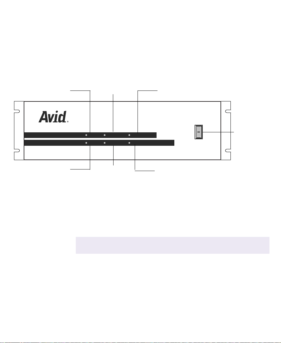
Meridien I/O Box Indicators
The Meridien I/O box provides six indicators along with a power
switch on the front of the box (see Figure 1-1). When you turn on the
Meridien I/O box, the indicators will turn on and off as it goes
through its power-on self-test (POST). After the POST, the 48 kHz and
POWER indicators remain on.
44.1 kHz AUDIO SYNC PULL DOWN
44.1 kHz
AUDIO SYNC
48 kHz
VIDEO SYNC
48 kHz VIDEO SYNC POWER
Figure 1-1 Meridien I/O Box Indicators
PULL DOWN
POWER
O
l
Power switch
Ta bl e 1- 3 lists the indicator functions.
Table 1-3 Meridien I/O Box Indicator Functions
Indicator Function
44.1 kHz The 44.1 kHz indicator is on when 44.1 kHz digital audio
is connected to the Meridien I/O box.
Do not use 44.1-kHz digital audio. The
c
NewsCutter accepts and outputs only 48 kHz.
48 kHz The 48 kHz indicator is on when 48 kHz digital audio is
connected to the Meridien I/O box.
26
Page 27

Table 1-3 Meridien I/O Box Indicator Functions (Continued)
Indicator Function
AUDIO SYNC The audio synchronized indicator is on when audio is
detected by the Meridien I/O box.
VIDEO SYNC The video synchronized indicator is on when video is
detected by the Meridien I/O box.
PULL DOWN The pulldown indicator is on when performing a telecine
film-to-tape transfer whereby 24-fps film material is
adapted to the 30-fps NTSC videotape format. Extra
pulldown fields are eliminated to achieve true 24-fps film
editing.
This function is not used in NewsCutter.
n
POWER The power indicator is on when the Meridien I/O box
power switch is in the on (I) position.
Checking the Installation Materials
When you purchase NewsCutter, you should receive the following
items in the package. Make sure you have everything before you start.
• NewsCutter system
A computer with specific peripheral boards for recording, editing,
and playing back clips. Included with the computer is a keyboard
and mouse. An optional rack-slide rail kit is available for
mounting the NewsCutter system in a rack.
• NewsCutter application key
This copy-protection device (also called a dongle) attaches to the
parallel port on your computer. A parallel printer can be
connected to the application key if you want a local printer.
27
Page 28

• Meridien I/O box
In a separate package, you will find a Meridien I/O box that
connects to the NewsCutter system. The Meridien I/O box
provides the video and audio interface connectors for the system.
• VGA cable
The hardware items in the shipping box include a standard 15-pin
VGA cable for connecting the UI monitor to the VGA adapter
installed in the NewsCutter system.
• Audio and video cables
The Meridien II digital media board set includes a Meridien
digital media cable that connects NewsCutter to the Meridien I/O
box.
• Serial adapter (Rosetta Stone)
A serial adapter is included for remote video deck control through
COM1 of the NewsCutter system. The adapter converts the
NewsCutter RS-232 signals to RS-422.
• NewsCutter CD-ROMs (2)
One CD-ROM contains the NewsCutter application. NewsCutter
ships from Avid with the application already loaded on the
system. If you ever need to reinstall the application, see the Avid
NewsCutter Release Notes for instructions.
The second CD-ROM provides you with a copy of the NewsCutter
application HTML-based, context-sensitive Help and an online
version of the printed documentation (in PDF format).
28
Page 29

• NewsCutter documentation:
- Avid NewsCutter Setup Guide (this guide)
- Avid NewsCutter Getting Started Guide
- Avid NewsCutter Release Notes
- Avid NewsCutter Upgrade Instructions
- Avid NewsCutter User’s Guide
- Avid NewsCutter Effects Guide
- Avid NewsCutter Quick Reference
- Avid NewsCutter Help
Other items you need to supply:
• XLR cables for audio connections
• Speakers
• Speaker wire (or cables) to connect speakers
• Broadcast-quality BNC cables for connecting video devices
• Flat-tip and #2 Phillips-head screwdrivers should be available for
component installation, setup, or attaching an optional
rack-mount kit to NewsCutter
• Wrist strap (recommended for grounding when handling circuit
boards)
Rack-Mounting Kits
If you have purchased an optional rack-mount kit for NewsCutter,
install the kit before making any connections to the NewsCutter
system. A stationary rail is attached to each side of the system and the
sliding rails are attached to the rack. The NewsCutter system typically
requires a minimum of five rack units. (Your system might require
29
Page 30
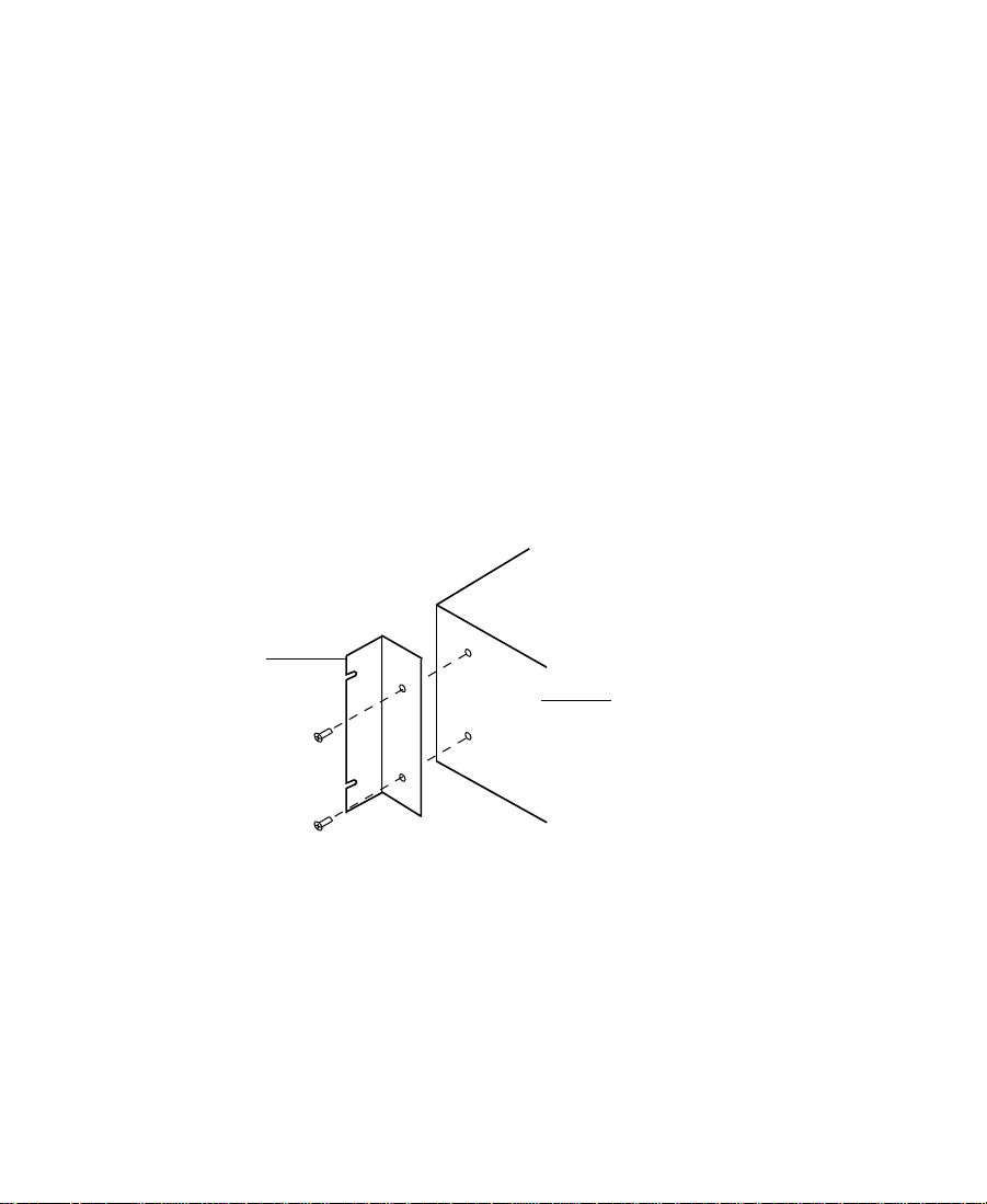
Bracket
more.) Detailed instructions for attaching the rails are included with
the kit.
The Meridien I/O box also comes with two rack-mount brackets.
Allow three rack units for the Meridien I/O box in the rack.
To attach the brackets to your Meridien I/O box:
1. Locate the two brackets and four screws that come with the
Meridien I/O box.
2. Position one of the brackets so that the two holes in the bracket
line up with the holes in the side of the Meridien I/O box (see
Figure 1-2).
3. Secure the bracket with the screws provided.
4. Repeat steps 2 and 3 for the other side.
Figure 1-2 Meridien I/O Box
30
Meridien I/O box
Page 31

CHAPTER 2
Setting Up the NewsCutter System
This chapter provides instructions for connecting the keyboard,
mouse, application key, UI monitor, and Avid Meridien I/O box to
NewsCutter.
This chapter also provides instructions on connecting external SCSI
storage devices to NewsCutter.
The instructions in this chapter use generic illustrations representing
the type of connector found on the back of the NewsCutter system. For
the exact connector locations, see the documentation that is provided
by the computer manufacturer.
n
Before you connect any cables, install the NewsCutter system into your rack
(see Chapter 1 for more rack-mounting information).
31
Page 32

Before You Begin
Before you begin installing the system, do the following:
• Unpack all the boxes that came with the hardware kit.
• Check the contents of the hardware kit against the packing list to
confirm that you have received all the parts.
• Position the hardware components.
Arranging Components
Before you start to connect and install equipment for NewsCutter, set
up your system components, especially monitors and keyboards, in
positions that allow you easy access to them.
Start by placing the PC, monitor(s), keyboard, mouse, and optional
speakers in positions that are comfortable for viewing and operating
the system. The Meridien I/O box and the audio I/O device must be
placed close to each other. They are connected by cables that are 2 feet
(0.61 meters) in length.
n
n
Allow at least 6 inches (152.4 mm) clearance between the monitor(s) and
optional speakers to avoid possible magnetic interference between the devices.
Place MediaDrive, MediaDock, and the F/C subsystem hardware
close together. Position the remaining components, such as video
decks, the VLXi, and additional audio I/O device and video interface
hardware, in locations that are easily accessible.
Figure 2-1 shows an example arrangement of a configured
NewsCutter system, including a UI monitor, Playback monitor, video
deck, Avid Meridien I/O box, MediaDock, speakers, and amplifier.
Your system might look different than the one shown and might include
additional hardware.
32
Page 33

Video deck
Speaker UI monitor
Keyboard
Figure 2-1 Configured System Layout
Assembling the System
The system uses peripheral boards to support video, audio,
compression, and improved data transfer to the hard drives. The
boards are located in the PCI slots inside the personal computer or in
the Meridien I/O box (an Avid-designed standalone box).
Playback monitor
Mouse
Speaker
Amplifier
VLX
44.1 kHz
kHz
48
SCSI IDSCSI ID
Slots Slots
ActAct
WideWide
DualbusDualbus
FansFans
Pwr 2Pwr 2
Pwr 1Pwr 1
V-LAN VLX
O
l
PULL DOWN
AUDIO SYNC
POWER
VIDEO SYNC
i
Meridien I/O box
NewsCutter
MediaDock
n
All systems shipped directly from Avid, or from an Avid Reseller, have
peripheral boards already installed in the PC and Meridien I/O box.
Make sure that the peripheral boards are installed in the PC and
Meridien I/O box before you continue with the setup instructions.
Ta bl e 2- 1 lists the supported slot configuration for NewsCutter on the
IBM
®
IntelliStation
®
Z Pro system. Use this information when you
install optional boards.
33
Page 34

The IBM IntelliStation Z Pro provides seven expansion slots. Slot 1,
originally containing an Accelerated Graphics Port (AGP) board, has
been removed by Avid and is not used in NewsCutter. The Ultra 160
SCSI LVD controller board, Meridien digital media board, and EDC
board are pre-installed.
Figure 2-2 identifies the slots and the installed boards for the IBM
IntelliStation Z Pro.
Ta b le 2 - 1 lists the expansion slot assignments for the installed and
optional boards.
n
Ultra 160 SCSI controller board
If your NewsCutter system is not an IBM IntelliStation Z Pro, see the
Avid NewsCutter Upgrade Instructions for slot placement guidelines.
These instructions are provided with the shipping items that come with
NewsCutter.
Slot 1
Digital media board
Edit display controller board
Figure 2-2 IBM IntelliStation Z Pro — Rear View
Slot 7
34
Page 35

Table 2-1 Avid NewsCutter Expansion Slot Assignments
a
Slot
1 AGP slot Empty (AGP board removed)
2 PCI slot (32-bit bus) SDTI adapter (option) or available slot
3 PCI slot (32-bit bus) Fibre Channel to Avid Unity/Fibre Channel to
4 PCI slot (32-bit bus) First SCSI LVD controller board
5 PCI slot (32-bit bus) Digital media board with DV 50 daughter board
6 PCI slot (64-bit bus) Edit display controller (EDC) board
7 PCI slot (64-bit bus) Available slot (a digital media board cannot be
a. There is an Avid slot guide sticker that provides specific PCI slot
locations for each PCI board in NewsCutter. The slot guide sticker
is on the inside of the panel you remove when accessing the PCI
boards.
Description
Playback device/Second SCSI LVD controller
board
used)
Ta bl e 2 -2 lists the available peripheral board types for the Meridien
I/O box.
Figure 2-3 shows the locations of the installed boards in the Meridien
I/O box.
35
Page 36

Table 2-2 Meridien I/O Box Peripheral Board Locations
Board Type Location
Meridien two-channel audio interface boards
a
Top and middle
slots
Meridien video I/O board Bottom slot
Meridien serial digital I/O board (option) Attaches to the
video I/O board
a. The Meridien I/O box supports two 2-channel audio interface
boards, labeled Channels 1 and 2 for the middle slot and
Channels 3 and 4 for the top slot, which together provide
4-channel audio.
Two-channel audio boards
AUDIO IN
AUDIO IN
COMPONENT
COMPOSITE
IN
ININ
IN
MIC
MIC CHAN 1
Y
COMPOSITE
REF
CHAN 3
R-Y B-Y
AUDIO OUT
-10
-10
GAIN 1
CHAN 4
CHAN 3
CHAN 2
Y
S-VIDEO
OUT 1
GAIN 2
+4
AUDIO OUT
-10
-10
GAIN 1
+4
CHAN 1
OUT
B-Y
R-Y
S-VIDEO
OUT 3
OUT 2
AES / EBU
S / PDIF
IN
SLAVE CLOCK
OUT
OUT
OUT
S / PDIF
OUT
IN
OUT
LTC
IN
IN
CHAN 4
AES / EBU
GAIN 2
IN
CHAN 2
OUT 1 OUT 2 OUT 3IN
DIGITAL VIDEO
SYSTEM
OUT
IN / OUT
OUT
Video I/O board
c
Serial digital I/O board (option)
Figure 2-3 Meridien I/O Box Rear Panel Board Slots
Before you begin assembling your system, check the release notes
that came with the system to make sure that there are no changes,
additions, or deletions to the following procedures.
36
Page 37

Connecting the Keyboard and Mouse
NewsCutter uses industry-standard PS/2-style keyboard and mouse
input devices.
You must connect the keyboard and mouse to the connectors on the
back of the NewsCutter system. The instructions to connect the
keyboard and mouse are specific to the PC you are using and are
located in the user documentation for your specific PC.
To connect your keyboard and mouse, refer to your PC documentation
before using the following general guidelines:
1. Unpack the keyboard and mouse that ship with the NewsCutter
system.
2. Plug the keyboard and mouse cables into the PS/2-style
connectors on the back of the NewsCutter (see Figure 2-4).
The PS/2-style connectors have keyboard and mouse icons beside
the connectors or are color coded.
n
PS/2 connector
Use PS/2-style extension cables with the keyboard and mouse when
NewsCutter is rack-mounted.
KeyboardMouse
Figure 2-4 Keyboard and Mouse Connection
37
Page 38

Installing the Application Key
The application key (also called a dongle) is a copy-protection device.
Without the application key, the NewsCutter application will not run.
To install the application key:
1. Plug the application key into the parallel port on the back of your
NewsCutter (see Figure 2-5).
2. Secure the application key to the connector with the attached
screws.
c
Parallel port connector
n
Do not overtighten the application key screws.
Application key
Figure 2-5 Application Key Connection
You can still use a local parallel printer (or any other compatible device
requiring use of the parallel port) even though the application key is
connected to the parallel port. The application key allows bidirectional parallel
port signals to pass to and from the printer (or other compatible device).
38
Page 39

Connecting the UI Monitor
The video graphics array (VGA) cable that comes with your UI
monitor has two 15-pin connectors. This cable connects your UI
monitor to the display controller board in the NewsCutter system and
carries video signals from NewsCutter to the UI monitor.
n
Edit display controller
board in NewsCutter
The following instructions explain how to connect a monitor provided by
Avid. Avid provides standard VGA connections for the UI monitor. If you use
a different monitor on your system, see the user’s guide that accompanies the
monitor to complete the monitor installation or contact the monitor reseller.
To connect NewsCutter to the UI monitor:
1. Locate the VGA cable in the hardware kit.
2. Attach the male end of the cable to the 15-pin VGA connector on
the back of the NewsCutter system (see Figure 2-6).
VGA connector
UI monitor
cable
Figure 2-6 VGA Cable Connection
3. Connect the other 15-pin (female) end of the VGA cable (labeled
Monitor) to the VGA input conector on the back of UI monitor.
39
Page 40

n
Use a VGA-style extension cable with the UI monitor when NewsCutter is
rack-mounted.
4. Attach the ac power cord to the ac power connector on the back of
the monitor.
5. Plug the ac power cord into a power strip.
For more information, check the documentation that comes with your
monitor.
Connecting NewsCutter to the Meridien I/O Box
All audio and video interfacing with NewsCutter is done through a
Meridien digital media cable. The Meridien digital media cable
connects the Meridien I/O box to the NewsCutter system.
To attach the cable:
1. Locate the Meridien digital media cable. This 6-foot (1.8-meter)
cable ships with the NewsCutter hardware kit.
n
c
An optional 50-foot cable can be ordered from Avid.
2. Plug one end of the Meridien digital media cable into the
connector labeled SYSTEM IN/OUT on the Meridien I/O box.
Tighten the screws on the cable to secure it in place (see
Figure 2-7).
Do not overtighten the digital media cable screws.
3. Attach the other end of the Meridien digital media cable to the
digital media board M port connector on the back of the
NewsCutter system. Tighten the screws on the cable to secure it in
place (see Figure 2-7).
40
Page 41

Meridien I/O box
r
e
Power cord
4. Plug the power cords into the power connector on both
NewsCutter and the Meridien I/O box. Plug the other end of each
power cord into an ac power source.
M port connector
on the NewsCutter
SYSTEM IN/OUT connecto
MC
Digital media board
in NewsCutter
Meridien digital media cabl
Figure 2-7 Connection Between NewsCutter and Meridien I/O
Box
Avid MediaDrive or MediaDock Connection
This section provides information about connecting Avid-approved
MediaDrive storage devices to NewsCutter. This information also
applies to optional MediaDock drives.
Do not record your media to the internal system drive. Use external
SCSI hard drives to store your media. Avid does not recommend
storing NewsCutter media files on non-Avid drives and cannot ensure
reliable or high-quality performance except on Avid-approved drives.
Avid offers external drives that have been qualified for video and
audio media, referred to as MediaDrives (or optional MediaDock
41
Page 42

drives). MediaDrives and MediaDock drives can also store nonmedia
files.
n
n
Avid recommends that you use the standard 40-inch (101.6-cm),
high-density, 68-pin to 68-pin SCSI cable supplied in the hardware kit for
connecting the first SCSI drive to the system. An active SCSI terminator is
also required for terminating the last drive in the chain.
If you are connecting multiple external SCSI drives, connect
Avid-approved drives according to the documentation that comes
with the drives. Avid-recommended drives come with the following
documentation:
• Avid MediaDrive rS LVD Setup and User’s Guide ships with the
individual MediaDrives.
• Avid MediaDock LVD Setup and User’s Guide ships with the media
docking station.
NewsCutter systems installed on the IBM IntelliStation Z Pro platform
come with SCSI hardware already installed. The back of the system
contains two 68-pin, high-density SCSI connectors for connecting a
SCSI cable between the NewsCutter and the first external SCSI drive.
These connectors are mounted on a SCSI controller board installed in a
PCI slot on the back of the system.
Some NewsCutter systems do not use the IBM IntelliStation Z Pro platform.
If your NewsCutter system is not an IBM IntelliStation Z Pro, see the
Avid NewsCutter Upgrade Instructions for the location and configuration
of SCSI hardware in your system. These instructions are provided with the
shipping items that come with NewsCutter.
NewsCutter systems with two SCSI connectors on the back are
dual-channel SCSI systems (see Figure 2-8).
42
Page 43

n
To ensure proper NewsCutter performance on the IBM IntelliStation Z Pro
platform, connect the SCSI cable to the dual-channel SCSI connector on the
SCSI controller board installed in the PCI slot. Do not connect the cable to the
system’s built-in SCSI port. NewsCutter will not operate correctly if
connected to the built-in SCSI port.
CHANNEL 1 CHANNEL 2
Figure 2-8 Dual-Channel SCSI Connections
You can have more than one MediaDrive attached to NewsCutter in a
daisy-chained connection described in the documentation supplied
with the MediaDrive.
When attaching multiple SCSI drives, assign the SCSI IDs from 0 to 6
and 8 to 15. The last drive in the chain must be terminated.
See the documentation that comes with the MediaDrive for
information on setting SCSI IDs and terminating the chain.
n
Typically, SCSI ID 0 is assigned to the internal SCSI drive if your
NewsCutter has an internal SCSI drive installed. For specific information
about the internal SCSI device IDs, see the manufacturer’s documentation.
Supported MediaDrives and MediaDock Storage Devices
Avid supports several families of MediaDrive enclosures and
MediaDock Shuttle packs. Ta b le 2 - 3 lists the families, their
specifications, and their available capacities. For additional
information on a specific MediaDrive or MediaDock shuttle, see the
documentation that ships with the MediaDrive or the MediaDock
shuttle.
43
Page 44

If you need additional information or if you have any questions,
contact Avid Customer Support at all 800-NEWS-DNG (639-7364).
n
Family Name SCSI Type RPM Drive Type
iS Pro Fast, wide 7200 Fixed MediaDrive and
iS Plus Fast, wide 10,000 MediaDock shuttle 9 GB, 18 GB
rS Plus Fast, wide 10,000 Fixed MediaDrive 9 GB, 18 GB
iS Plus LVD LVD 10,000 MediaDock shuttle 9 GB, 18 GB
iS LVD LVD 10,000 MediaDock shuttle 18 GB, 36 GB
iS 160/LVD 160/LVD 10,000 MediaDock shuttle 18 GB, 36 GB, 73 GB
rS LVD LVD 10,000 Fixed MediaDrive 9 GB, 18 GB, 36 GB
rS 160/LVD 160/LVD 10,000 Fixed MediaDrive 18 GB, 36 GB, 73 GB
The family name of your drive can be found on the front of the MediaDrive or
MediaDock shuttle.
Table 2-3 MediaDrive and MediaDock Shuttle Information
Available
Capacities
9 GB, 18 GB
MediaDock shuttle
44
Page 45

Connecting Avid Drives to NewsCutter
To connect the SCSI cable to an external MediaDrive or MediaDock:
1. Align and connect one end of the 68-pin, high-density SCSI cable
to the 68-pin SCSI connector on the first external SCSI drive.
2. Align and connect the other end of the 68-pin SCSI cable with the
SCSI connector on the back of NewsCutter (see Figure 2-9 for a
typical system).
Connect the cable to the connector labeled Channel 1.
3. Secure the SCSI connector by tightening the two screws.
CHANNEL 1 CHANNEL 2
SCSI connector
in NewsCutter
n
c
Screw
Screw
Figure 2-9 Connecting the MediaDrive or MediaDock SCSI
Cable to NewsCutter
The SCSI connectors might orient vertically rather than horizontally
(depending on your system).
4. Turn on the external Avid drive(s). Allow approximately 10 to 15
seconds for each MediaDrive or MediaDock to complete its
self-test.
Turning on your NewsCutter before each Avid drive completes its
self-test could cause the system to ignore the drive.
SCSI cable to
Avid drives
45
Page 46

5. Turn on NewsCutter and wait for the Windows NT operating
system to boot.
Before you can store files on the Avid drives, you must format and
partition them with the Windows NT operating system (see the
documentation that comes with your drive). The NewsCutter
application uses the NT File System (NTFS).
n
If you have more than one hard disk drive and performance is a high priority,
you can use striping across multiple external hard drives. Striping increases
the read and write speed. For more information, see your Windows NT
documentation and “Drive Striping Requirements” on page 48.
Data Rate Calculations
Use Ta bl e 2 - 4 though Ta b l e 2 - 7 to determine how many minutes of
audio and video you can store on your Avid drive. (These numbers are
approximate.)
Calculations include a 10 percent system overhead factor.
n
Table 2-4 Drive Storage Capacities (Minutes) for NTSC Video
Resolution 9 GB 18 GB 36 GB 73 GB
DV 25 Single-stream 40 80 160 320
DV 25 Dual-stream 20 40 80 160
DV 50 Single-stream 20 40 80 160
DV 50 Dual-stream 10 20 40 80
46
Page 47

Table 2-5 Drive Storage Capacities (Minutes) for PAL Video
Resolution 9 GB 18 GB 36 GB 73 GB
DV 25 Single-stream 50 100 200 400
DV 25 Dual-stream 25 50 100 200
DV 50 Single-stream 25 50 100 200
DV 50 Dual-stream 13 25 50 100
Table 2-6 Data Rate Storage Calculations for NTSC Video
Resolution
DV 25 data rates
Single-stream,
four-channel audio
Dual-stream,
four-channel audio
DV 50 data rates
Single-stream,
four-channel audio
Dual-stream,
four-channel audio
Megabytes
per Second
4.0 240 4.3
8.0 480 2.1
7.75 465 2.2
15.5 930 1.1
Megabytes
per Minute
Minutes
per Gigabyte
47
Page 48

Table 2-7 Data Rate Storage Calcula tions for
PAL Video
Resolution
DV 25 data rates
Single-stream,
four-channel audio
Dual-stream,
four-channel audio
DV 50 data rates
Single-stream,
four-channel audio
Dual-stream,
four-channel audio
Drive Striping Requirements
NewsCutter systems that operate at DV 25 and DV 50 dual-stream
resolutions might require drive striping as listed in Ta b le 2 - 8 (for
NTSC video) and Ta b le 2 - 9 (for PAL video) for supported MediaDrive
and SCSI controllers.
Megabytes
per Second
3.2 192 5.3
6.4 384 2.7
6.2 372 2.7
12.4 744 1.4
Megabytes
per Minute
Minutes
per Gigabyte
Driving striping is a method that maximizes NewsCutter performance
according to the data rate and performance characteristics of the SCSI
controller and the Avid drives. Striping the connected Avid drives
divides the data sent from the SCSI controller and shares it among
each drive in the system, while treating the connected drives as one
volume, helping to ensure operation at higher resolutions.
48
Page 49

Table 2-8 Drive Striping Requirements for NTSC Video
Resolution
DV 25 single-stream, four
channels audio
DV 25 single-stream, four
channels audio/complex
titling
DV 25 dual-stream, four
channels audio
DV 25 dual-stream, four
channels audio/complex
titling
DV 50 single-stream, four
channels audio
DV 50 single-stream, four
channels audio/complex
titling
DV 50 dual-stream, four
channels audio
Single-ended,
Fast, wide
iS9, iS18
Fast, wide
iSPlus, rSPlus,
iS LVD,
rS LVD
MediaDrives
with Ultra 160
LVD SCSI
1-way 1-way 1-way 1-way
1-way 1-way 1-way 1-way
1-way 1-way 1-way 1-way
2-way 1-way 1-way 1-way
1-way 1-way 1-way 1-way
2-way 1-way 1-way 1-way
2-way 2-way 2-way 1-way
DV 50 dual-stream, four
4-way, 2 buses 2-way, 2 buses
a
2-way 1-way
channels audio complex titling
a. rS Plus single-ended only. MediaDock iS Plus is Low-Voltage Differential (LVD), so only one
bus is required.
49
Page 50

Table 2-9 Drive Striping Requirements for PAL Video
Resolution
DV 25 single-stream, four
channels audio
DV 25 single-stream, four
channels audio/complex
titling
DV 25 dual-stream, four
channels audio
DV 25 dual-stream, four
channels audio/complex
titling
DV 50 single-stream, four
channels audio
DV 50 single-stream, four
channels audio/complex
titling
DV 50 dual-stream, four
channels audio
Single-ended,
Fast, wide
iS9, iS18
Fast, wide
iSPlus, rSPlus,
iS LVD,
rS LVD
MediaDrives
with Ultra 160
LVD SCSI
1-way 1-way 1-way 1-way
1-way 1-way 1-way 1-way
1-way 1-way 1-way 1-way
2-way 1-way 1-way 1-way
1-way 1-way 1-way 1-way
2-way 1-way 1-way 1-way
2-way 2-way 2-way 1-way
DV 50 dual-stream, four
4-way, 2 buses 2-way, 2 buses
a
2-way 1-way
channels audio complex titling
a. rS Plus single-ended only. MediaDock iS Plus is LVD, so only one bus is required.
50
Page 51

Optional NewsCutter Connections
NewsCutter can work as a standalone system or as part of a broadcast
network. In a broadcast network, NewsCutter can share media files
with other systems connected to the network or send edited news
sequences for broadcast to a remote play-to-air device.
Use one of the following connections if you are planning on using
NewsCutter in a workgroup environment:
• Local Area Network Workgroup Configuration
• Fibre Channel Workgroup Configuration
• Avid Unity for News Workgroup Configuration
For information on setting up NewsCutter in a local area network, see
“Local Area Network Workgroup Configuration” on page 52.
For information on setting up NewsCutter in a Fibre Channel
workgroup configuration, see “Fibre Channel Workgroup
Configuration” on page 53 or “Avid Unity for News Workgroup
Configuration” on page 55.
n
Chapter 6 provides information on setting up NewsCutter in a
workgroup configuration for connection to a playback device.
The playback device is an optional component used with NewsCutter to create
a workgroup environment that enhances speed and content quality in news
editing and news production. See the release notes that come with the
playback device for specific setup instructions.
51
Page 52

Local Area Network Workgroup Configuration
NewsCutter systems include an RJ-45 Ethernet network connector for
setting up NewsCutter in a local area network. Avid recommends that
you use a category-5 unshielded twisted pair (UTP) cable when
connecting the NewsCutter to a network. For more information on the
installed network interface, see the documentation provided by the
computer manufacturer.
You can use the Ethernet network to set up NewsCutter in a
workgroup environment.
An optional connection kit is available for connecting NewsCutter to a
playback device in an Ethernet workgroup configuration.
n
n
This type of workgroup is also called a standalone or peer-to-peer workgroup.
Figure 2-10 shows a graphical representation of a typical Ethernet
workgroup configuration that connects to an Avid AirSPACE NP
video file server playback device.
This information might change in accordance with feature and performance
enhancements. Depending on your specific playback device, your
configuration might differ.
™
52
Page 53

Incoming
Feeds
AirSPACE NP Record
AirSPACE NP Play-to-Air
Baseband
Connection
Workgroup
Avid
NewsCutter
Edit
Figure 2-10 Ethernet Workgroup Configuration
Fibre Channel Workgroup Configuration
An optional Fibre Channel connection kit is available for connecting
NewsCutter to a playback device in a Fibre Channel workgroup
configuration. If you are installing a Fibre Channel connection kit in
NewsCutter, follow the instructions provided by the computer
manufacturer for removing the cover and installing an expansion
board.
Newsroom
Automation
System
Ethernet
Figure 2-11 shows a graphical representation of a typical Fibre
Channel workgroup configuration that connects to a Grass Valley
Group
Profile® PDR400 video file server playback device.
53
Page 54

n
This information might change in accordance with feature and performance
enhancements. Depending on your specific playback device, your
configuration might differ.
Incoming
Feeds
Ingest
Profile Record
Baseband
Connection
Play-to-Air
Profile Play-to-Air
Fibre Channel
Workgroup
Newsroom
Automation
System
Avid
NewsCutter
Ethernet
Edit
Figure 2-11 Fibre Channel Workgroup Configuration
54
Page 55

Avid Unity for News Workgroup Configuration
NewsCutter can work as part of a broadcast network such as the Avid
Unity for News workgroup.
The Avid Unity for News workgroup environment consists of the
following functional components:
• Supported Avid editing systems (such as NewsCutter).
• Avid Unity MediaManager server to track and manage Avid Unity
media files. When connected to an F/C network, a workgroup
client uses the MediaManager server to share Avid Unity files
with clients within the workgroup.
• Avid Unity TransferManager server to manage the transfer of
media files to and from another workgroup’s TransferManager
server (typically, over an Ethernet network). The TransferManager
server also allows you to transfer media files from a feed (ingest)
device or send finished sequences to a playback device.
n
n
The TransferManager server is not required equipment in a MediaNet
environment. However, you must connect a TransferManager server in your
workgroup if you want to share media files with other workgroups in the
MediaNet environment.
• Avid Unity MediaNet file server and storage subsystem.
• A Fibre Channel (F/C) network that connects the NewsCutter
systems, MediaManager server, and TransferManager server to
the file server and storage subsystem.
An optional Fibre Channel connection kit is available for connecting
NewsCutter to the Avid Unity MediaNet environment.
• An Ethernet network that is used as a general-purpose
communications network connecting all the system components.
An Ethernet network can also be used by the TransferManager
server to transfer media files between workgroups.
55
Page 56

Figure 2-12 shows a flow diagram of a typical shared storage
Avid Unity for News workgroup configuration.
MediaNet File
server
Avid Unity
shared storage
Fibre Channel
Supported
Avid editors
Workgroup
MediaManager
server
TransferManager
server
Ethernet
To another workgroup’s
TransferManager server
Figure 2-12 Avid WorkGroup Flow Diagram
The purpose of the workgroup is to enable collaborative workflows by
allowing multiple NewsCutter editors to share media files.
Figure 2-13 shows the necessary connections if you are planing to
transfer media files over a network to an optional playback device.
The sequences are cued and sent to air by an optional broadcast
control system (BCS). The BCS controls the playback devices with a
serial connection.
56
Page 57

n
For information on connecting NewsCutter in an Avid Unity for News
workgroup, refer to the Avid Unity Workgroup Setup Guide.
Playback servers
News
feed
Other
workgroups
MM
NC
TM
NewsCutter
VTR
Feed record server (ingest)
PDR400 video server
TransferManager
server
Fibre Channel
NewsCutter
VTR
MediaManager server
(metadata storage)
...
Ethernet
PDR400 video server
AirSPACE video server
iNEWS
BCS
TransferManager
server
NewsCutter
VTR
= Fibre Channel
= Ethernet
= Serial
NRCS = Newsroom Control System
BCS = Broadcast Control System
TM = TransferManager server
MM = MediaManager server
NC = NewsCutter editing system
Newscast
Avid Unity
shared storage
iNEWS
NRCS
Newscast
MediaNet File
server
Figure 2-13 Sample Layout for an Avid Unity for News
Workgroup
57
Page 58

For more information about setting up NewsCutter in an Avid Unity
for News workgroup, see the following documentation:
• Avid Unity Workgroup Setup Guide
• Avid Unity TransferManager Release Notes
• Avid Unity TransferManager User’s Guide
• Avid Unity MediaManager Release Notes
• Avid Unity MediaManager User’s Guide
• Avid Unity MediaManager Administrator’s Guide
SDTI Connection
The Serial Data Transport Interface (SDTI) was developed to provide a
standard for digital audio, video, and data interchange between
cameras, VTRs, servers, and editing systems such as NewsCutter.
SDTI uses standard SDI cabling and support mechanisms.
Connections between devices are established point-to-point, as they
are with standard video and audio signals. The benefits of SDTI
include the following:
• A single cable carries compressed video and up to four channels of
uncompressed 48 kHz audio.
• Transfer rates at up to four times (4X) real time can be achieved.
• SDI cabling, routers, and switches can be used to route SDTI
signals.
The SDTI option kit for NewsCutter allows the transfer of DVCAM
DVCPRO, and DVCPRO 50 compressed digital video to and from
SDTI-equipped VTRs as listed in Ta bl e 2 - 10 . This is achieved through
the installation of SDTI driver software and an SDTI adapter board
that installs in a PCI slot in the NewsCutter system. These items come
with the SDTI option kit available from Avid.
58
™
,
Page 59

For instructions on how to install the adapter board, see “SDTI Device
Connections” on page 69.
The SDTI option is active only for the Record tool and the Digital Cut
tool in NewsCutter.
Once you have set up SDTI as your input source (see the Avid
NewsCutter User’s Guide), recording proceeds as it does for any other
input source. NewsCutter automatically adjusts to one of the SDTI
signal types listed in Ta bl e 2 - 1 0 .
Table 2-10 SDTI Signal Types
Signal Type Resolution Channels Sample Rate
1X DVCAM DV 25 2 48 kHz
1X DVCPRO DV 25 3 48 kHz
1X DVPRO 50 DV 50 4 48 kHz
4X DVCAM DV 25 2 48 kHz
4X DVPRO DV 25 2 48 kHz
59
Page 60

CHAPTER 3
Connecting Audio and Video Devices
This chapter describes how to connect audio and video devices to
NewsCutter. Topics include:
• Avid Meridien I/O Box Connections
• SDTI Device Connections
This chapter includes instructions for connecting cables between the
Meridien I/O box and the audio and video devices.
The Meridien I/O box communicates with NewsCutter through the
Meridien digital media cable. This cable provides all the audio, video,
timecode, and reference signals to NewsCutter. Chapter 2 describes
the connection between NewsCutter and the Meridien I/O box.
n
n
Install the Meridien I/O box into your rack before you connect any cables (see
Chapter 1 for more rack-mounting information).
This chapter also describes how to connect SDTI video devices to
NewsCutter.
You must have the optional SDTI adapter board in your NewsCutter system
to connect to SDTI devices.
60
Page 61

Avid Meridien I/O Box Connections
The audio and video interact with NewsCutter through the Meridien
I/O box. The Meridien I/O box provides connectors for all the
standard audio and video input and output signals. The connections
to the Meridien I/O box will vary, depending upon your deck and
type of audio and video signals used.
Audio Interface Connections
The Meridien I/O box provides the following analog and digital
connections:
• Four analog audio channels; four sets of input and output
connectors.
• One analog microphone connector; accepts powered or phantom
power microphones. Choose the audio input setting in the Record
tool to match your type of microphone.
n
n
The MIC connector on the second audio interface board (channels 3 and 4) is
disabled.
• One digital Audio Engineering Society/European Broadcasting
Union (AES/EBU) audio channel; one set of input and output
connectors. Each AES/EBU channel has left and right channel
information. AES/EBU is a format used with professional digital
audio equipment (for example, audio from a videotape or CD).
®
• One digital Sony
audio channel; one set of input and output RCA connectors. Some
digital audiotapes (DATs) found in consumer digital audio
equipment use S/PDIF.
The NewsCutter system accepts and outputs only 48-kHz digital audio. Do
not use 44.1-kHz digital audio.
/Philips® Digital Interface Format (S/PDIF)
61
Page 62

The audio interface usually is connected to an amplifier with speakers
for monitoring audio during recording and playback. Pay careful
attention to the audio levels while you are recording. Use a mixer or
amplifier to control the audio levels.
Figure 3-1 shows the audio hardware connections.
All audio cables are customer supplied.
Speakers
Microphone input
Audio amplifier
Audio channel inputs
Audio output to deck or
other audio destination
Audio channel outputs
Speakers can connect directly or through an amplifier.
(Speakers and amplifier are optional.)
Powered
speakers
AES/EBU digital I/O
Phono (RCA) jacks
for S/PDIF digital I/O
Avid Meridien I/O box
Audio input from deck or
other audio source
Figure 3-1 Audio I/O Connections
62
Page 63

Video Interface Connections
Figure 3-2 shows the connectors used to connect the customer-
supplied Playback monitor and video deck to the Meridien I/O box.
These connectors are used for video input and output from decks,
satellite feeds, or routers. A customer-supplied Playback monitor
displays incoming video when the system is recording, or it displays
edited material during playback. These analog video connections can
be either composite or component. If you are connecting digital video
to the Meridien I/O box, see “Serial Digital Interface Connections”
on page 64.
The video connections also require a reference signal (black burst
generator or house clock) to lock audio and video sampling together to
keep video and audio synchronized. See “Connecting the Reference
Signal” on page 64.
All video cables are customer supplied.
Component video input connections
(from deck, router, or satellite feed)
Composite video input connection
(from deck, router, or satellite feed)
S-Video input connection
(from deck, router, or satellite feed)
Figure 3-2 Video I/O Connections
Component video output connections
(to deck, router, or monitor)
Avid Meridien I/O box
S-Video output connection
(to deck or monitor)
Three composite video output connectors
(to deck, router, or monitor)
63
Page 64

Serial Digital Interface Connections
The serial digital interface board is optional. If you need to install the
optional serial digital interface board, see “Serial Digital Interface
Board Installation” on page 137. Figure 3-3 shows the BNC
connectors used to connect the serial digital video to the Meridien I/O
box. These connectors are used for video input and output from decks,
satellite feeds, or routers.
The video connections also require a reference signal (black burst
generator or house clock) to lock audio and video sampling together to
keep video and audio synchronized. See “Connecting the Reference
Signal” on page 64.
All video cables are customer supplied.
Avid Meridien I/O box
Serial video input connection
(from deck, router, or satellite feed)
Figure 3-3 Serial Digital Video I/O Connections
Connecting the Reference Signal
All broadcast systems require an analog video reference signal. The
video reference signal must be provided to several of the system
components and must meet standard NTSC or PAL specifications.
64
Three serial video output connectors
(to deck, router, or monitor)
Page 65

The video reference signal can be a black burst generator or the house
black reference signal (see Figure 3-4). The reference signal connects to
the Meridien I/O box, V-LAN VLXi
controller, and deck.
All cables are customer supplied.
Video reference output
to video deck
Black burst generator
or house reference video source
Video reference output
to REF connector
V-LAN VLX
Figure 3-4 Reference Signal Connections
Controlling a Video Deck
Video deck
BB3BB1 BB2
Meridien I/O box
Video reference output
to REF connector
Optional
Term inator
SERIAL PARALLEL REF LAN CF
i
VLX TRANSMITTER VLX 2R DUAL RECEIVER
TIMECODE A
SERIAL A SERIAL B
IN INOUT OUT
TIMECODE B
AC
You can control up to two video decks remotely by using serial
connections between NewsCutter and the video deck. This serial
connection requires an RS-232 to RS-422 cable adapter for each video
deck connected to NewsCutter.
65
Page 66

A serial adapter kit, called the Rosetta Stone, is provided with
NewsCutter. The serial adapter kit contains:
• An RS-232 to RS-422 serial adapter
• Two serial cables; male 9-pin connectors at both ends
To video deck
n
If you need to connect and control more than two video decks, see
“Connecting a V-LAN VLXi Controller and GPI Devices” on page 67.
To connect the remote control:
1. Locate the serial adapter kit.
2. Attach one end of the first 9-pin cable to the end of the serial
adapter labeled RS-232 (see Figure 3-5).
3. Attach the other end of the first 9-pin cable to the NewsCutter
COM1 serial port (see Figure 3-6).
Serial adapter RS-232 connectionRS-422 connection
To NewsCutter
LEDs
Figure 3-5 Video Deck Control Cabling
4. Attach one end of the second 9-pin cable to the end of the serial
adapter labeled RS-422.
5. Attach the other end of the second 9-pin cable to the remote serial
port of the video deck.
6. Set the video deck’s Remote mode switch to Remote.
66
Page 67

n
If the LEDs on the serial adapter do not light when the connections are
completed with the equipment turned on, the serial adapter is connected
backward. Before the remote control becomes functional, you must also choose
the COM port in the Deck Configuration dialog box of the NewsCutter
application (see the NewsCutter Help for more information).
Connecting a V-LAN VLXi Controller and GPI Devices
NewsCutter can control multiple video decks through a video local
area network (V-LAN) VLXi deck controller. Use a generalpurpose interface (GPI) connected to the V-LAN to trigger functions in
NewsCutter.
Video Local Area Network
The V-LAN VLXi shown in Figure 3-6 consists of one V-LAN
transmitter and a dual V-LAN VLXi receiver. The receiver contains
two deck controllers. Both the transmitter and receiver are internally
linked. The V-LAN VLXi connects to NewsCutter through a direct
serial connection.
Each V-LAN VLXi supports two video decks. Daisy-chain multiple
V-LAN VLXi units if you need to add more video decks.
General-Purpose Interface
The VLXi-GT contains six programmable GPI input and output
terminals. The GPI input terminal can be configured to trigger
NewsCutter to Play, Record, Cue, and Stop. You can configure the GPI
output terminal to provide Stop, Record, and Play status.
Assign the VLXi-GT to V-LAN node addresses 16 through 19. LAN
connections of more than 50 feet must have a terminator. For more
information, see the Vid eomedia VLXi User’s Guide.
67
Page 68

The V-LAN VLXi deck controller and VLXi-GT connect to NewsCutter
as shown in Figure 3-6.
All cables are customer supplied.
Six GPI input and output terminals
IN OUT1IN OUT2IN OUT3IN OUT4IN OUT5IN OUT
SERIAL LAN CF
6
V-LAN connection
Terminator
(required when cable length
is more than 50 feet)
AC
VLXi-GT (GPI)
SERIAL PARALLEL REF LAN CF
VLX TRANSMITTER VLX 2R DUAL RECEIVER
VLX
i
transmitter
serial input
Figure 3-6 V-LAN VLX
Master Clock Connection
When you are controlling the video deck through a serial remote
control or a V-LAN VLXi controller, the deck timecode is utilized in
the application. Avid strongly recommends synchronizing
NewsCutter to the house master clock (SMPTE for NTSC, and EBU for
PAL) when using a satellite feed or manually controlling a video deck.
TIMECODE A
SERIAL A SERIAL B
IN INOUT OUT
TIMECODE B
Serial connection
to deck remote
Serial cable to RS-232 COM1 port
on NewsCutter
i
Deck Control
AC
Video deck
V-LAN VLX
i
68
Page 69

The house master clock connects to the Timecode IN connector on the
Meridien I/O box (see Figure 3-7). This timecode is used throughout
the NewsCutter system.
Figure 3-7 Timecode Connections
SDTI Device Connections
This section describes how to connect NewsCutter to a Serial Digital
Transport Interface (SDTI) device.
SDTI device functionality is an optional feature of NewsCutter that
provides enhanced video and audio quality at higher transmission
rates.
n
The Meridien I/O box and the SDTI deck must be genlocked to the same house
clock (see “Master Clock Connection” on page 68 for information on
connecting to a house clock). If you are not using a common house clock to
synchronize the components, you will eventually experience an overrun or
underrun error.
The SDTI option kit includes an SDTI adapter board, a breakout box,
and a CD-ROM containing the SDTI software.
Timecode IN
connector
Timecode OUT
connector
(not functional)
n
Instructions for installing the SDTI software are included with your SDTI
option kit or in the Avid NewsCutter Release Notes.
69
Page 70

You must install the optional SDTI adapter board in the correct PCI
slot in your NewsCutter. See Figure 2-2 and Table 2-1 on page 35 for
slot placement guidelines in an IBM IntelliStation Z Pro.
n
n
n
If your NewsCutter system is not an IBM IntelliStation Z Pro, see the
Avid NewsCutter Upgrade Instructions for slot placement guidelines.
SDTI audio and video interfacing is done through the breakout box
and A/V cables (supplied by the SDTI device manufacturer) and the
SDTI adapter board.
For instructions on connecting cables from the SDTI device to the breakout
box, see the documentation supplied by the SDTI device manufacturer.
To install the SDTI adapter board and connect the breakout box:
1. Locate the SDTI adapter board and the breakout box supplied
with your SDTI adapter kit.
2. Install the SDTI adapter board in the NewsCutter system.
For board installation procedures, see the peripheral board installation
instructions that came with your system.
3. As shown in Figure 3-8, align and attach the SDTI male connector
to the female connector on the SDTI adapter board installed in
NewsCutter.
4. Secure the breakout box to the SDTI adapter by tightening the
screws.
70
Page 71

SDTI adapter board
in NewsCutter
5. Install the SDTI driver software located on the CD-ROM that
comes with the SDTI adapter. To install the software, follow the
instructions that come with the SDTI option kit or in the Avid
NewsCutter Release Notes.
Screws
Ref In
Breakout box
SDI/SDTI
Out
SDI/SDTI
Loop Out
SDI/SDTI
In
Figure 3-8 SDTI Interface Connection
71
Page 72

72
Page 73

CHAPTER 4
Running the System Diagnostics
After you have set up NewsCutter, test the system to make sure that
the Avid components and peripheral boards are functioning properly.
Avid supplies a system diagnostics program (Avid System Test Pro) to
help you verify that the Meridien II digital media board set and the
Meridien I/O box are working properly. In addition, a storage
exerciser (Avid StorEx) is supplied for testing the MediaDrives.
n
The Avid System Test Pro application can test the Avid components and
peripheral boards only after you start and then quit NewsCutter.
This chapter provides the information required to run the diagnostics.
For more information about the function of specific buttons and
windows, use the Help provided within the diagnostics.
To start the Help, start the Avid System Test Pro application and
choose Help from the Help menu. The Help Topics window opens.
Double-click a book icon in the Help window to display the topics.
The application also provides context-sensitive Help. While the
diagnostic window is active, press F1 to display information about
that window.
73
Page 74

The Avid System Test Pro reads the Meridien I/O box default state
when you start the diagnostics. These defaults are used during the
diagnostics. An example default state could be NTSC mode,
Composite In, and Component Out. To change the default state of the
Meridien I/O box, run the Avid Video I/O Utility application.
Turning On the System
After you have connected the keyboard, mouse, application key,
monitors, MediaDrives, and Meridien I/O box, you should turn on the
system to make sure it starts properly before you start NewsCutter.
To turn on the system:
1. Make sure all devices are properly plugged into a surge protector
or wall outlet.
2. Turn on the UI monitor, Meridien I/O box, and MediaDrives.
3. Turn on NewsCutter by pressing the power switch to the on (I)
position on the front of the unit.
The system starts. System-specific information is displayed on the
UI monitor.
4. Select Windows NT Workstation 4.0 when asked to select the
operating system.
74
Page 75

Avid System Test Pro
The Avid System Test Pro diagnostics are a set of tests that check the
Meridien II digital media board set and the Meridien I/O box. Run
these diagnostics before you begin editing with your NewsCutter.
Avid System Test Pro is divided into two separate test suites:
• Standard — Tests all the board sets with no intervention needed by
the user
• External/User Interaction — Tests the I/O portions of the board sets
and needs user intervention such as connecting cables and
answering questions in a dialog box
Avid System Test Pro contains Help that provides information on each
button, window, and test. This section provides:
• A brief explanation of the user interface
• A procedure for running standalone diagnostics
• Cable connections needed for the interactive portion of the
diagnostics
• A procedure for running interactive diagnostics
n
Read this section completely before you attempt to run the diagnostics.
Starting Avid System Test Pro
To start Avid System Test Pro:
1. Close all open applications.
2. Click the Start button, point to Programs, point to Avid, point to
Utilities, and click Avid System Test Pro.
Avid System Test Pro starts, and a dialog box appears.
3. Click OK.
75
Page 76

The main window opens. To exit the Avid System Test Pro
diagnostics, choose Quit from the File menu.
Quick Start Dialog Box
The Avid System Test Pro Quick Start dialog box appears when you
start the Avid System Test Pro diagnostic program (see Figure 4-1).
This dialog box tells you what you need to do to start testing the
standard set of diagnostics using all test program defaults. The
defaults include the use of NTSC video.
Figure 4-1 Avid System Test Pro Quick Start Dialog Box
Understanding the Main Window
The Avid System Test Pro for NewsCutter window (see Figure 4-2)
appears the first time you run the diagnostics. This window contains
the test selections, buttons needed to start and stop the diagnostics,
and indicators for test status.
76
Page 77

Pause button Stop button
Start button
Test suite tabs
Test tree
Expansion
button
Toolbar
Item name
Item check box
Item status
System status
Figure 4-2 Avid System Test Pro Window
The Avid System Test Pro window contains:
• Toolbar — A VCR-like user interface that provides control over
running the diagnostics. When you first start the diagnostics, only
the Start button in the toolbar is active.
• Test suite tabs — Allow the user to select the Standard or
External/User Interaction test suite to run. Each suite has a status
indicator that provides status for each suite selected.
- Standard test suite contains tests that run without special
cabling or user interaction.
- External/User Interaction suite contains tests that require user
interaction and special cabling. For information on how to
cable the system for these tests, see “Running the
External/User Interaction Diagnostics Suite” on page 81.
• Test tree — A section of the window that contains expansion
buttons, item names, item check boxes, and item status.
77
Page 78

• Expansion button — Clicking an expansion button (+) switches
the level of detail for a given item. For example, clicking + shows
the groups within the item.
• Item name — The name of the board being tested or the test name
under that board if the item is expanded.
• Item check box — Selects the item for testing. When the check box
contains an X, the item is selected for testing. By default, all tests
associated with the Standard suite are selected when you first run
the diagnostic program from the desktop. Items are deselected
when the box is empty.
• Item status — Provides status of each test (see the Help for a
complete explanation).
• System status — Displays the pass or fail status of the entire
system.
You should run both suites of Avid System Test Pro diagnostics to
ensure that NewsCutter is functioning properly. You should run the
Standard suite first and then the External/User Interaction suite if the
Standard suite passes.
Understanding the Avid System Test Preferences Window
The Avid System Test Preferences window opens when you choose Set
Preferences from the Options menu. The Avid System Test Preferences
window controls the way testing occurs. The window has two tabs:
Test Control tab and Video Subsystem tab.
78
Page 79

Test Control Tab
The Test Control tab allows you to select the manner in which errors
are to be handled and how many times you want to repeat the test (see
Figure 4-3).
Figure 4-3 Avid System Test Preferences Window
Video Subsystem Tab
— Test Control Tab
The Video Subsystem tab (see Figure 4-4) allows you to override the
default video standard (NTSC, NTSCj, or PAL) of the Meridien I/O
box. The Meridien I/O box defaults to NTSC in the United States. If
the default is set to NTSC and you want to test the PAL functions, you
must change the video standard to PAL and restart the diagnostic (the
settings are looked at only during the diagnostic startup).
79
Page 80

Figure 4-4 Avid System Test Preferences Window
— Video Subsystem Tab
Running the Standard Diagnostics Suite
To run the Standard diagnostics suite:
1. Start the diagnostics as described in “Starting Avid System Test
Pro” on page 75.
The Avid System Test Pro Quick Start dialog box appears,
explaining how to run the Standard diagnostics using default
settings.
2. Click OK.
3. Click the Start button in the toolbar in the main window.
The Standard diagnostics run with status shown in the Item status
boxes in the main window.
4. Do one of the following:
• If the tests pass, continue testing at “Running the
External/User Interaction Diagnostics Suite” on page 81.
80
Page 81

• If any test fails, the Error Log window opens, showing which
board failed the test.
If this is the first time the tests have failed, see Chapter 5,
“Troubleshooting” for possible solutions to the problem.
If you have tried the solutions in Chapter 5 and the
diagnostics still fail, contact your Avid Reseller.
Running the External/User Interaction Diagnostics Suite
The External/User Interaction diagnostics suite tests the following
assemblies:
• Meridien II digital media board set — Interactive test that requires
you to respond to dialog boxes as they appear.
• Meridien video I/O board — External test that requires you to
cable selected inputs to selected outputs before you run the tests.
The test might be NTSC, NTSCj, or PAL, depending upon the
selection in the Avid System Test Preferences window.
• Meridien audio I/O boards — External test that requires you to
cable the channel 1, 2 , 3, and 4 inputs to the outputs before you
run the tests.
All External/User Interaction tests displayed under these items are
deselected by default, and you must select each test to run them.
To cable the boards in the Meridien I/O box to run the interactive
tests, locate the following cables (all cables are customer supplied):
• Audio cable — Two male XLR connectors on one end and two
female XLR connectors at the other or two individual audio cables.
Avid recommends a Beldon 8451 audio cable or equivalent.
• Component video cable — Three BNC connectors at both ends of
the cable or three individual BNC video cables. Avid recommends
a Beldon 8281 video cable with 75-ohm video connectors or
equivalent.
81
Page 82

• Composite video cable — One BNC connector at each end.
• S-Video cable — One 6-pin, S-video connector at each end.
Cable the Meridien I/O box as described in the following section, and
then see “Running the External Tests” on page 85 for instructions.
External Diagnostics Audio Cabling
Connect the audio channel inputs to the audio channel outputs on the
audio I/O boards with the audio test cable (see Figure 4-5).
1. Attach CHAN 1 OUT to CHAN 1 IN.
2. Attach CHAN 2 OUT to CHAN 2 IN.
3. Attach CHAN 3 OUT to CHAN 3 IN.
4. Attach CHAN 4 OUT to CHAN 4 IN.
AUDIO IN
AUDIO IN
COMPONENT
COMPOSITE
MIC CHAN 1
IN
ININ
IN
REF
MIC
CHAN 2
Y
R-Y B-Y
S-VIDEO
COMPOSITE
GAIN 1
-10
CHAN 1
B-Y
Y
R-Y
OUT 1
OUT 3
OUT 2
Figure 4-5 Audio Test External Cabling
External Diagnostics Component Video Cabling
Connect the component video cable to the video I/O board as shown
in Figure 4-6.
1. Connect one end of the cable (using the three BNC connectors) to
COMPONENT OUT on the video I/O board as follows:
a. Attach one green wire BNC connector to the connector labeled
Y OUT.
82
AUDIO OUT
-10
+4
AUDIO OUT
-10
GAIN 1
+4
OUT
S-VIDEO
AES / EBU
GAIN 2
GAIN 2
CHAN 2
OUT 1 OUT 2 OUT 3IN
DIGITAL VIDEO
SYSTEM
OUT
IN / OUT
S / PDIF
IN
OUT
OUT
IN
AES / EBU
S / PDIF
IN
OUT
IN
OUT
LTC
SLAVE CLOCK
IN
OUT
OUT
Page 83

b. Attach one red wire BNC connector to the connector labeled
R-Y OUT.
c. Attach one blue wire BNC connector to the connector labeled
B-Y OUT.
AUDIO IN
AUDIO IN
IN
COMPONENT
IN
COMPOSITE
CHAN 3
MIC
MIC CHAN 1 CHAN 2
ININ
Y
R-Y B-Y
COMPOSITE
REF
AUDIO OUT
-10
-10
GAIN 1
CHAN 4
CHAN 3
+4
AUDIO OUT
-10
-10
GAIN 1
+4
CHAN 1
OUT
B-Y
Y
R-Y
S-VIDEO
OUT 1
S-VIDEO
OUT 3
OUT 2
AES / EBU
GAIN 2
CHAN 4
GAIN 2
CHAN 2
OUT 1 OUT 2 OUT 3IN
DIGITAL VIDEO
SYSTEM
OUT
IN / OUT
S / PDIF
IN
IN
IN
AES / EBU
SLAVE CLOCK
OUT
OUT
S / PDIF
OUT
IN
OUT
LTC
IN
OUT
OUT
Figure 4-6 Component Video External Cabling
2. Connect the other end of the cable (using the three BNC
connectors) to the COMPONENT IN on the video I/O board as
follows:
a. Attach the green wire BNC connector to the connector labeled
Y IN.
b. Attach the red wire BNC connector to the connector labeled
R-Y IN.
c. Attach the blue wire BNC connector to the connector labeled
B-Y IN.
External Diagnostics Composite Video Cabling
Connect the composite video cable to the video I/O board as shown in
Figure 4-7.
1. Connect one end of the cable to COMPOSITE IN on the video
board.
2. Connect the other end of the cable to COMPOSITE OUT 1 on the
video I/O board.
83
Page 84

AUDIO IN
CHAN 3
MIC
AUDIO IN
MIC CHAN 1
CHAN 2
IN
ININ
COMPONENT
Y
R-Y B-Y
IN
COMPOSITE
S-VIDEO
COMPOSITE
REF
AUDIO OUT
-10
-10
GAIN 1
CHAN 4
CHAN 3
+4
AUDIO OUT
-10
-10
GAIN 1
+4
CHAN 1
OUT
B-Y
Y
R-Y
OUT 1
S-VIDEO
OUT 3
OUT 2
AES / EBU
GAIN 2
CHAN 4
GAIN 2
CHAN 2
OUT 1 OUT 2 OUT 3IN
DIGITAL VIDEO
SYSTEM
OUT
IN / OUT
S / PDIF
IN
AES / EBU
SLAVE CLOCK
OUT
OUT
S / PDIF
OUT
IN
OUT
LTC
IN
OUT
OUT
IN
IN
Figure 4-7 Composite Video External Cabling
n
output and run the test again for each one.
External Diagnostics Serial Digital Video Cabling
Connect the serial digital cable to the serial digital interface board (if
installed) as shown in Figure 4-8.
To test OUT 2 and OUT 3, move the output end of the cable to the untested
n
The serial digital interface board is optional and might not be installed in
your Avid Meridien I/O box.
1. Connect one end of the cable to IN on the DIGITAL VIDEO
portion of the serial digital interface board.
2. Connect the other end of the cable to OUT 1 on the DIGITAL
VIDEO portion of serial digital interface board.
AUDIO IN
CHAN 4
CHAN 3
MIC
AUDIO IN
MIC CHAN 1
CHAN 2
IN
ININ
COMPONENT
Y
R-Y B-Y
IN
COMPOSITE
S-VIDEO
COMPOSITE
REF
AUDIO OUT
-10
-10
GAIN 1
CHAN 3
+4
AUDIO OUT
-10
-10
GAIN 1
+4
CHAN 1
OUT
B-Y
Y
R-Y
OUT 1
S-VIDEO
OUT 3
OUT 2
AES / EBU
GAIN 2
CHAN 4
GAIN 2
CHAN 2
OUT 1 OUT 2 OUT 3IN
DIGITAL VIDEO
SYSTEM
OUT
IN / OUT
S / PDIF
IN
AES / EBU
SLAVE CLOCK
OUT
OUT
S / PDIF
OUT
IN
OUT
LTC
IN
OUT
OUT
IN
IN
Figure 4-8 Serial Digital Video External Cabling
84
Page 85

n
output and run the test again for each one.
External Diagnostics S-Video Cabling
Connect the S-Video cable to the video I/O board as shown in
Figure 4-9.
1. Connect one end of the S-Video cable to S-VIDEO IN on the video
I/O board.
2. Connect the other end of the cable to S-VIDEO OUT on the video
I/O board.
To test OUT 2 and OUT 3, move the output end of the cable to the untested
Figure 4-9 S-Video External Cabling
Running the External Tests
To run the External/User Interaction tests:
1. Start the diagnostics as described in “Starting Avid System Test
Pro” on page 75.
The Avid System Test Pro Quick Start dialog box appears,
explaining how to run the Standard diagnostics by using the
default settings.
2. Click OK.
3. Click the External/User Interaction tab in the main window.
AUDIO IN
CHAN 3
MIC
MIC CHAN 1
IN
ININ
IN
REF
CHAN 4
CHAN 2
Y
R-Y B-Y
S-VIDEO
COMPOSITE
AUDIO IN
COMPONENT
COMPOSITE
AUDIO OUT
-10
-10
GAIN 1
CHAN 3
+4
AUDIO OUT
-10
-10
GAIN 1
+4
CHAN 1
OUT
B-Y
Y
R-Y
OUT 1
S-VIDEO
OUT 3
OUT 2
AES / EBU
GAIN 2
CHAN 4
GAIN 2
CHAN 2
OUT 1 OUT 2 OUT 3IN
DIGITAL VIDEO
SYSTEM
OUT
IN / OUT
S / PDIF
IN
AES / EBU
SLAVE CLOCK
OUT
OUT
S / PDIF
OUT
IN
OUT
LTC
IN
OUT
OUT
IN
IN
85
Page 86

4. Loop back the Meridien I/O box connectors as explained in the
previous sections.
5. Click the Start button in the toolbar in the main window.
The External/User Interaction diagnostics run with the status
shown in the Item status boxes in the main window.
6. Answer any dialog box questions that might appear.
7. Do one of the following:
• If the tests pass, choose Quit from the File menu and consider
that your NewsCutter system is working properly.
• If any test fails, the Error Log window opens, showing which
board failed the test. First check the setup instructions in
Chapter 2 and Chapter 3 to make sure the system is set up
properly. Then, see the Error Condition topic in the diagnostic
Help for possible solutions to the problem.
If you have tried the solutions and the diagnostics still fail, contact
your Avid Reseller.
Understanding the Error Log Window
When an error is detected during a test, a dialog box appears,
informing you an error has occurred. Choose Error Log from the
Window menu (see Figure 4-10) to display information on all errors
that have occurred since the application started or since the error log
was cleared. Each entry lists the failing board, the failing test, and the
time of the failure. If you double-click on a failure, a more detailed
error window opens.
Figure 4-10 Error Log Window
86
Page 87

Avid StorEx
The information in the Error Log window can be saved in text (.TXT)
format by choosing Save Error Log from the File menu. Once you have
saved the error log, you can open the saved file with any text editing
application and print it.
Avid StorEx is a general-purpose, hard-drive exerciser program that
verifies the operation of SCSI hard drives connected to a SCSI
accelerator board or Fibre Channel (F/C), PCI-based NewsCutter.
n
StorEx runs with Avid drives only. StorEx does not work with non-Avid,
third-party drives.
The program also provides test status information that is helpful for
troubleshooting a drive problem. Your local Avid Reseller might
instruct you to use StorEx as part of the process of troubleshooting a
problem with a hard drive.
StorEx requires a working NewsCutter system in order to function
properly. The F/C controller and the SCSI accelerator board must be
functioning and be able to accept commands and return results.
StorEx is installed with NewsCutter and is located on the system hard
drive in the C:\Program Files\Avid\Utilities\StorEx folder.
Running Avid StorEx
To run Avid StorEx:
1. Quit all applications that are running on your NewsCutter.
2. Click the Start button, point to Programs, point to Avid, point to
Utilities, and then click Avid StorEx.
The Avid StorEx Disk Test window opens.
87
Page 88

3. Select the devices you want to test by clicking the check box for
each device in the Test display (see “Test Display” on page 91).
4. Choose Preferences from the Options menu, and select the
preferences you need for the selected tests.
c
Avid suggests that you use the default settings in the Preferences
window. You should not choose any destructive tests without first
talking to your Avid Reseller.
5. Start the testing by clicking the Start button in the toolbar (see
“Toolbar” on page 90) or by choosing Start from the Testing menu
(see “Menus” on page 89).
6. When the test is complete, you can view the status in the Console
display (see “Console Display” on page 92).
If you have any failures, contact your Avid Reseller.
Avid StorEx Disk Test Window
The Avid StorEx Disk Test window provides information on the
devices available for testing and the results of each test (see
Figure 4-11).
88
Page 89

Menu
Toolbar
Test
display
Console
display
Figure 4-11 Avid StorEx Disk Test Window
The window is divided into four areas:
•Menu
Menus
• Toolbar
• Test display
• Console display
The StorEx menus are at the top of the display and provide the
following functions:
• File — Allows you to quit the program by choosing Exit from the
File menu.
• View — Allows you to define what you want to see in the Console
display. The available choices are:
89
Page 90

Toolbar
- Toolbar
- Tests (also select by pressing and holding Alt+1)
- Console (also select by pressing and holding Alt+2)
• Tes t i ng — Allows you to control the testing. The available choices
are:
-Start
-Pause
-Stop
- Default Tests
• Options — Allows you to open the Test Preferences window (see
“Test Preferences Window” on page 92) and to define the type of
error that causes the test to stop:
- Stop On Hard Error
- Stop On Any Error
• Help — Lists the StorEx revision level.
The toolbar is a VCR-like user interface that provides control over the
running of the diagnostic. When you first start the diagnostic, only the
start portion of the toolbar is active. Each button is explained in
Figure 4-12.
Start
Pause
Stop
Stop on
Hard Error
Stop on
Any Error
Summary
Figure 4-12 Avid StorEx Toolbar
90
Page 91

Test Display
SCSI bus
Target ID
The Test display (see Figure 4-13) appears by default in the Avid
StorEx Disk Test window when you start StorEx. The Test display
shows the SCSI buses and attached disks found by StorEx during the
scan of the SCSI buses, the device status boxes, and the check boxes. To
open the Test display, choose Tests from the View menu or press and
hold Alt+1. To close the Test display, choose Tests from the View menu
or press and hold Alt+1. The Test display allows you to:
• Show the system devices attached to the adapters found by StorEx
when it starts.
• See the status of the devices on the system in the status box.
• Select the devices you want to test by clicking the check box.
Status box Check box
Device number
Figure 4-13 Avid StorEx Test Display
The target ID is actually the physical disk address of the disk on the
SCSI bus set by switches at the rear of the disk drive.
The device number is a number assigned by StorEx that helps to
identify the drives in the display console printout. The device
numbers have nothing to do with the SCSI bus to which the disk is
attached.
91
Page 92

n
The Test display is shown in Figure 4-13 with the status box and check box
on the right side of the display. The Test display is really a window within the
window and can be sized independently. If you make the window smaller
without resizing the Test display, you can cut the status box and check box
from view. If you want to make the window smaller, you should resize the Test
display to the smaller size first, and then resize the window.
Console Display
The Console display shows a record of the output from StorEx. To
open the Console display, choose Console from the View menu or
press and hold Alt+2. To close the Console display, choose Console
from the View menu or press and hold Alt+2.
Test Preferences Window
The Test Preferences window opens when you choose Preferences
from the Options menu (see Figure 4-14). The Test Preferences
window controls the way testing occurs. The window has two tabs,
Tests and Options.
Tests Tab
When you click the Tests tab, a display appears that allows you to
choose the tests that you want to run on the selected hard drives.
The tests are divided into two types: nondestructive tests and
destructive tests.
• Nondestructive tests only read the data that is on the hard drive.
They do not write any data to the hard drive.
• Destructive tests write data to the hard drive and then read that
data. The data is then compared to the original data to verify that
the write and read functions of the hard drive are working
correctly. These tests destroy any data and file system structure on
the hard drive.
92
Page 93

Figure 4-14 Avid StorEx Test Preferences Window — Tests Tab
The nondestructive tests include:
• Sequential Read — Reads data from every sector on the drive,
starting at the first sector and ending at the last sector. The test
verifies data integrity without destroying data and checks for
error correction code (ECC) errors.
• Random Read — Randomly reads data from sectors on the drive
for a specified amount of time (see “Options Tab” on page 95).
The test simulates normal drive activity without destroying data
and checks for ECC errors.
• Single Sector Read — Reads the data from single, randomly
selected sectors on the drive for a specified amount of time (see
“Options Tab” on page 95). The test exercises drive head
positioning, produces a large amount of SCSI bus control traffic,
and checks for ECC errors.
93
Page 94

• Converge/Diverge Read — Reads each sector on the drive,
beginning at the opposite ends of the drive (the first sector and the
last sector) and moving toward the center. It then repeats the test,
reading from the center to the ends. The test checks the seek
ranges of the drive, ensures that all sectors are read, and checks for
ECC errors.
The destructive tests include:
• Sequential Write/Read — Writes data to every sector and then
reads the data from the sector just written and compares it to the
original data. The test starts at the first sector on the drive and
ends at the last sector. The test verifies the write and read
capability of the entire drive.
• Random Write/Read — Randomly selects a starting sector, writes
data to a random number of sectors, and then reads the data from
those sectors and compares it to the original data for a specified
amount of time (see “Options Tab” on page 95). The test most
closely simulates the normal drive working environment.
• Single Sector Write/Read — Randomly selects a single sector,
writes data to the sector, and then reads the data from the sector
and compares it to the original data for a specified amount of time
(see “Options Tab” on page 95). The test is seek intensive and
produces a large amount of SCSI bus control traffic.
n
Clicking the Default button selects the default test setting, Random
Read (nondestructive test only).
You can select only one test out of all the available tests. The test you select is
performed on all the devices selected for test in the Test display. There is no
option for assigning a different test for each device. If a destructive
(Write/Read) test has been chosen (or mistakenly chosen), there will be one
last warning issued before the destructive test begins.
94
Page 95
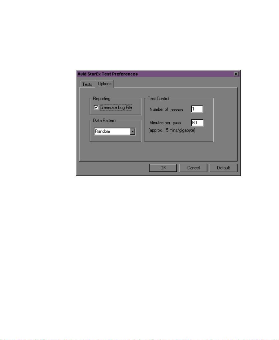
Options Tab
When you click the Options tab (see Figure 4-15), the display area is
divided into three panels: Reporting, Data Pattern, and Test Control.
Each panel contains test options that you can select before you run
Avid StorEx.
Figure 4-15 Avid StorEx Test Preferences Window
— Options Tab
The three panels are:
• Reporting — Allows you to create a log file containing all the
information shown in the Console display. Creating a log prevents
the loss of the results of a test run. The default log file name is
StorExNT_mmdd_hhmm.txt, where mmdd is the month and day
and hhmm is hour and minute. This information is stored in the
folder from which StorEx is executed.
Generate Log File is the default for all tests.
• Data Pattern — Determines the data patterns used for all write
tests. The data pattern selections are:
95
Page 96

Control Buttons
- Random writes a random data pattern to the hard drive by
using the operating system random-number generator to
create unique and unpredictable data.
- All Zeroes writes all zeroes to the hard drive.
- All Ones writes all ones to the hard drive.
- Pseudo Incrementing
- Alternating 1’s and 0’s
The default is Random.
• Test Control — Allows you to choose the number of times the test
executes and the number of minutes per pass the test runs.
- Number of Passes sets the number of times that all the tests are
run.
- Minutes per Pass sets the number of minutes that any random
test runs if no errors are encountered.
The default is 1 pass and 60 minutes.
The control buttons allow you to OK your selection, cancel your
selection, or return all selections in the Test Preferences window to the
default state by clicking the Default button.
96
Page 97

CHAPTER 5
Troubleshooting
When you are installing NewsCutter and using it for the first time,
you might encounter some problems. This chapter describes some of
the common symptoms, the possible causes, and solutions to them.
Table 5-1 No Display After Power-On
Possible Causes Possible Solutions
The VGA cable is not connected to
the Meridien II EDC board’s video
port.
AGP board is installed in
NewsCutter.
The monitor is connected to the
system VGA port instead of the
Meridien II digital media board set.
97
Connect the VGA cable to the Meridien
II EDC board’s video port. See Chapter
2.
If you are upgrading NewsCutter, check
to make sure the AGP board has been
removed. If it is installed, the system
might be looking at the AGP for video
signals instead of the Meridien II EDC
board. If the AGP board is installed,
remove it and reboot.
Connect the monitor to the Meridien II
digital media board set.
Page 98

Table 5-1 No Display After Power-On (Continued)
Possible Causes Possible Solutions
The Meridien II digital media
board set might be dislodged.
Vendor-supplied video board is
installed in NewsCutter.
Remove the cover according to the
computer manufacturer’s instructions,
and check that the circuit boards are
seated properly.
Remove vendor-supplied video board
from NewsCutter.
Table 5-2 Display Colors Are Incorrect
Possible Causes Possible Solutions
Unsupported resolution Right-click on the desktop and view
the Settings tab. NewsCutter
recommends 1024 x 768, 75 Hz, with
True Color in the Color Palette.
Bent pin on a cable connection Make sure cable connections do not
have bent pins.
Defective cable Check all cables and make sure they are
working correctly.
n
Optional speakers too close to
monitor
Move speakers far enough away from
screen so that magnetic field doesn’t
affect display colors.
Record the problem before attempting to correct it.
98
Page 99

Table 5-3 Cannot Initialize Meridien II Digital Media
Board Set
Possible Causes Possible Solutions
The Meridien II digital media board
set is installed but not seated correctly
in the PCI slot.
NewsCutter has stopped
running and has a condition that
is preventing it from restarting.
Error message 1. The base memory address could
Be sure that the digital media board
set is installed correctly in your
computer.
Contact your Avid Reseller for
assistance.
be conflicting with another
device. Check the system
resources.
2. Remove the Meridien II digital
media board set and make sure
all the components are seated
properly. Try restarting the
system to recheck the symptom.
If the error still exists, the
problem is with the digital
media board set.
99
Page 100

Table 5-4 UI Monitor Does Not Display Selected
Resolution
Possible Causes Possible Solutions
The monitor is not able to support
the selected resolution.
The monitor is not adjusted
correctly.
You have an incorrect monitor
cable.
Check your computer manual to be sure
that your monitor supports the
resolution you want to use. Avid
recommends 1024 x 768, 75 Hz, with
True Color in the Color Palette.
The monitor might need adjustment. The
controls that allow adjustment of the
vertical and horizontal planes might
need to be moved. Check your video
monitor manual for more information.
Make sure you are using the cable
supplied with your monitor.
Table 5-5 Security Failure
Possible Causes Possible Solutions
NewsCutter requires a hardware
security device called an
application key. The application
key is not attached securely or is
missing from the parallel port
on your system.
Check to see that the application key is
installed. See “Installing the
Application Key” on page 38.
After NewsCutter was installed,
the system was not restarted before
running the application for the first
time.
100
Restart the system.
 Loading...