

Page 1

Avid® NewsCutter
Setup Guide
Release 1.5
for the Windows NT® Operating System
a
tools for storytellers™
®
Page 2

© 1998–1999 Avid Technology, Inc. All rights reserved.
Avid NewsCutter Setup Guide • Part 0130-04395-01 Rev. A • November 1999
2
Page 3

Contents
Using This Guide
Who Should Use This Guide. . . . . . . . . . . . . . . . . . . . . . . . . . . . . . . . . 10
About This Guide
Symbols and Conventions
Using the Help System
If You Need Help
Related Information
If You Have Documentation Comments
How to Order Documentation
Chapter 1 Introduction
NewsCutter System Features. . . . . . . . . . . . . . . . . . . . . . . . . . . . . . . . . 16
Meridien I/O Box Indicators
Example System Layout
Checking the Installation Materials
Rack-Mounting Kits
. . . . . . . . . . . . . . . . . . . . . . . . . . . . . . . . . . . . . . . . . . . 11
. . . . . . . . . . . . . . . . . . . . . . . . . . . . . . . . . . . 11
. . . . . . . . . . . . . . . . . . . . . . . . . . . . . . . . . . . . . . 12
. . . . . . . . . . . . . . . . . . . . . . . . . . . . . . . . . . . . . . . . . . . 12
. . . . . . . . . . . . . . . . . . . . . . . . . . . . . . . . . . . . . . . . . 13
. . . . . . . . . . . . . . . . . . . . . . . 13
. . . . . . . . . . . . . . . . . . . . . . . . . . . . . . . . 14
. . . . . . . . . . . . . . . . . . . . . . . . . . . . . . . . . 19
. . . . . . . . . . . . . . . . . . . . . . . . . . . . . . . . . . . . . 20
. . . . . . . . . . . . . . . . . . . . . . . . . . . 21
. . . . . . . . . . . . . . . . . . . . . . . . . . . . . . . . . . . . . . . . 23
Chapter 2 Setting Up the NewsCutter System
Connecting the Keyboard and Mouse . . . . . . . . . . . . . . . . . . . . . . . . . 25
Installing the Application Key
Connecting the VGA Interconnect Cable
Connecting NewsCutter to the Meridien I/O Box
Avid MediaDrive Connection
Evaluating Drive Types
Data Rate Calculations
3
. . . . . . . . . . . . . . . . . . . . . . . . . . . . . . . 26
. . . . . . . . . . . . . . . . . . . . . . . . . . . . . . . . 31
. . . . . . . . . . . . . . . . . . . . . . . . . . . . . . . . . . 33
. . . . . . . . . . . . . . . . . . . . . . . . . . . . . . . . . . . 34
. . . . . . . . . . . . . . . . . . . . . . 27
. . . . . . . . . . . . . . . 30
Page 4

Optional NewsCutter Connections. . . . . . . . . . . . . . . . . . . . . . . . . . . . 35
Network Configuration
Fibre Channel Workgroup Configuration
. . . . . . . . . . . . . . . . . . . . . . . . . . . . . . . . . . 35
Chapter 3 Connecting Audio and Video Devices
Avid Meridien I/O Box Connections . . . . . . . . . . . . . . . . . . . . . . . . . . 36
Audio Interface Connections
Video Interface Connections
Serial Digital Interface Connections
Connecting the Reference Signal
Controlling a Video Deck
Connecting a V-LAN VLX
Video Local Area Network
General-Purpose Interface
Master Clock Connection
. . . . . . . . . . . . . . . . . . . . . . . . . . . . . 37
. . . . . . . . . . . . . . . . . . . . . . . . . . . . . . 39
. . . . . . . . . . . . . . . . . . . . . . . 40
. . . . . . . . . . . . . . . . . . . . . . . . . . 41
. . . . . . . . . . . . . . . . . . . . . . . . . . . . . . . . 42
i Controller and GPI Devices. . . . . . 43
. . . . . . . . . . . . . . . . . . . . . . . . . . . . 43
. . . . . . . . . . . . . . . . . . . . . . . . . . . . 43
. . . . . . . . . . . . . . . . . . . . . . . . . . . . . . . . 45
Chapter 4 Running the System Diagnostics
Turning On the System . . . . . . . . . . . . . . . . . . . . . . . . . . . . . . . . . . . . . . 47
Avid System Test Pro
Starting Avid System Test Pro
Quick Start Dialog Box
Understanding the Main Window
Understanding the Avid System Test Preferences Window
Running the Standard Diagnostics Suite
Running the External/User Interaction Diagnostics Suite
External Diagnostics Audio Cabling
External Diagnostics Component Video Cabling
External Diagnostics Composite Video Cabling
External Diagnostics Serial Digital Video Cabling
External Diagnostics S-Video Cabling
Running the External Tests
Understanding the Error Log Window
. . . . . . . . . . . . . . . . . . . . . . . . . . . . . . . . . . . . . . . . 47
. . . . . . . . . . . . . . . . . . . . . . . . . . . . 48
. . . . . . . . . . . . . . . . . . . . . . . . . . . . . . . . . . 49
. . . . . . . . . . . . . . . . . . . . . . . . . 49
. . . . . . . . . . . . . . . . . . . . . . . . . . . 58
. . . . . . . . . . . . . . . . . . 35
. . . 51
. . . . . . . . . . . . . . . . . . . 52
. . . . 53
. . . . . . . . . . . . . . . . . . . 54
. . . . . . . . 54
. . . . . . . . . 55
. . . . . . . 56
. . . . . . . . . . . . . . . . . 57
. . . . . . . . . . . . . . . . . . . . . 59
4
Page 5

Avid StorEx . . . . . . . . . . . . . . . . . . . . . . . . . . . . . . . . . . . . . . . . . . . . . . . . 59
Running Avid StorEx
Avid StorEx Disk Test Window
Menus
Toolbar
Test Display
Console Display
Test Preferences Window
Tests Tab
Options Tab
Control Buttons
. . . . . . . . . . . . . . . . . . . . . . . . . . . . . . . . . . . . . . . . . . . . . . 62
. . . . . . . . . . . . . . . . . . . . . . . . . . . . . . . . . . . . . . . . . . . . . 62
. . . . . . . . . . . . . . . . . . . . . . . . . . . . . . . . . . . . . . . . . . . . 65
. . . . . . . . . . . . . . . . . . . . . . . . . . . . . . . . . . . . 60
. . . . . . . . . . . . . . . . . . . . . . . . . . . . . . . . . . . . . . . . . 63
. . . . . . . . . . . . . . . . . . . . . . . . . . . . . . . . . . . . . 64
. . . . . . . . . . . . . . . . . . . . . . . . . . . . . . . . . . . . . . . . . 67
. . . . . . . . . . . . . . . . . . . . . . . . . . . . . . . . . . . . . 68
Chapter 5 Troubleshooting
Chapter 6 Setting Up Workgroups
Video Transfers. . . . . . . . . . . . . . . . . . . . . . . . . . . . . . . . . . . . . . . . . . . . . 77
Cabling the NewsCutter to the Workgroup
Connecting the NewsCutter and Playback Device for Ingest
Setting Up the Playback Device for Ingest
Setting Up the NewsCutter for Ingest
Transferring from the NewsCutter to the Playback Device
Transferring from the Playback Device to the NewsCutter
. . . . . . . . . . . . . . . . . . . . . . . . . . . 61
. . . . . . . . . . . . . . . . . . . . . . . . . . . . . . . . . 64
. . . . . . . . . . . . . . . . . 77
. 79
. . . . . . . . . . . . . . . . . 80
. . . . . . . . . . . . . . . . . . . . . . 81
. . . 82
. . . 84
Appendix A Servicing the Avid Meridien I/O Box
Avid Meridien Connectors . . . . . . . . . . . . . . . . . . . . . . . . . . . . . . . . . . . 85
Avid Meridien I/O Box Board Replacement
Serial Digital Interface Board Installation
5
. . . . . . . . . . . . . . . . . . . . 90
. . . . . . . . . . . . . . . . . . . . . 91
Page 6

Appendix B Supported Serial Control Video Decks
General Deck Selection Recommendations . . . . . . . . . . . . . . . . . . . . 94
Direct Serial Decks
Edit Decks
Record Decks
Play Decks
V-LAN Decks
Edit Decks
Record Decks
Play Decks
VTRs
. . . . . . . . . . . . . . . . . . . . . . . . . . . . . . . . . . . . . . . . . . . . . . . . . . . . . 103
. . . . . . . . . . . . . . . . . . . . . . . . . . . . . . . . . . . . . . . . . . 95
. . . . . . . . . . . . . . . . . . . . . . . . . . . . . . . . . . . . . . . . . . . . . . 95
. . . . . . . . . . . . . . . . . . . . . . . . . . . . . . . . . . . . . . . . . . . 97
. . . . . . . . . . . . . . . . . . . . . . . . . . . . . . . . . . . . . . . . . . . . . 98
. . . . . . . . . . . . . . . . . . . . . . . . . . . . . . . . . . . . . . . . . . . . . . . 98
. . . . . . . . . . . . . . . . . . . . . . . . . . . . . . . . . . . . . . . . . . . . . . 99
. . . . . . . . . . . . . . . . . . . . . . . . . . . . . . . . . . . . . . . . . . 101
. . . . . . . . . . . . . . . . . . . . . . . . . . . . . . . . . . . . . . . . . . . . 102
Appendix C Regulatory and Safety Notices
FCC Notice. . . . . . . . . . . . . . . . . . . . . . . . . . . . . . . . . . . . . . . . . . . . . . . . 104
Canadian ICES-003
European Union Notice
Australia and New Zealand EMC Regulations
. . . . . . . . . . . . . . . . . . . . . . . . . . . . . . . . . . . . . . . . . 105
. . . . . . . . . . . . . . . . . . . . . . . . . . . . . . . . . . . . . 105
Index
. . . . . . . . . . . . . . . . 106
6
Page 7

Figures
Figure 1-1 Meridien I/O Box Indicators . . . . . . . . . . . . . . . . . . . . . 19
Figure 1-2
Figure 1-3 Meridien I/O Box. . . . . . . . . . . . . . . . . . . . . . . . . . . . . . . 24
Figure 2-1 Keyboard and Mouse Connection. . . . . . . . . . . . . . . . . 26
Figure 2-2
Figure 2-3 VGA Interconnect Cable . . . . . . . . . . . . . . . . . . . . . . . . . 28
Figure 2-4 VGA Interconnect Cable Connections . . . . . . . . . . . . . 29
Figure 2-5
Figure 2-6
Figure 3-1
Figure 3-2 Video I/O Connections. . . . . . . . . . . . . . . . . . . . . . . . . . 39
Figure 3-3
Figure 3-4 Reference Signal Connections . . . . . . . . . . . . . . . . . . . . 41
Figure 3-5 Video Deck Control Cabling. . . . . . . . . . . . . . . . . . . . . . 42
Figure 3-6
Figure 3-7 Timecode Connections . . . . . . . . . . . . . . . . . . . . . . . . . . 45
Sample NewsCutter Layout . . . . . . . . . . . . . . . . . . . . . . 21
Application Key Connection . . . . . . . . . . . . . . . . . . . . . 27
Connection Between the NewsCutter and
Meridien I/O Box. . . . . . . . . . . . . . . . . . . . . . . . . . . . . . . 31
MediaDrive SCSI Connector. . . . . . . . . . . . . . . . . . . . . . 32
Audio I/O Connections . . . . . . . . . . . . . . . . . . . . . . . . . 38
Serial Digital Video I/O Connections. . . . . . . . . . . . . . 40
V-LAN VLXi Deck Control. . . . . . . . . . . . . . . . . . . . . . . 44
Figure 4-1 Avid System Test Pro Quick Start Dialog Box. . . . . . . 49
Figure 4-2
Figure 4-3 Avid System Test Preferences Window
Figure 4-4
Figure 4-5
Figure 4-6
Figure 4-7 Composite Video External Cabling. . . . . . . . . . . . . . . . 56
Avid System Test Pro for NewsCutter Window. . . . . 49
— Test Control Tab . . . . . . . . . . . . . . . . . . . . . . . . . . . . . 51
Avid System Test Preferences Window
— Video Subsystem Tab . . . . . . . . . . . . . . . . . . . . . . . . . 52
Audio Test External Cabling . . . . . . . . . . . . . . . . . . . . . 54
Component Video External Cabling . . . . . . . . . . . . . . . 55
7
Page 8

Figure 4-8 Serial Digital Video External Cabling . . . . . . . . . . . . . . 57
Figure 4-9 S-Video External Cabling . . . . . . . . . . . . . . . . . . . . . . . . 57
Figure 4-10
Error Log Window. . . . . . . . . . . . . . . . . . . . . . . . . . . . . . 59
Figure 4-11 Avid StorEx Disk Test Window. . . . . . . . . . . . . . . . . . . 61
Figure 4-12 Avid StorEx Toolbar . . . . . . . . . . . . . . . . . . . . . . . . . . . . 63
Figure 4-13
Avid StorEx Test Display . . . . . . . . . . . . . . . . . . . . . . . . 63
Figure 4-14 Avid StorEx Test Preferences Window
— Tests Tab. . . . . . . . . . . . . . . . . . . . . . . . . . . . . . . . . . . . 65
Figure 4-15
Avid StorEx Test Preferences Window
— Options Tab . . . . . . . . . . . . . . . . . . . . . . . . . . . . . . . . . 67
Figure 6-1
Figure 6-2
Audio, Video, and Serial Connections . . . . . . . . . . . . . 80
Digital Cut Tool . . . . . . . . . . . . . . . . . . . . . . . . . . . . . . . . 83
Figure A-1 Avid Meridien Audio Connectors. . . . . . . . . . . . . . . . . 86
Figure A-2
Avid Meridien Video Connectors . . . . . . . . . . . . . . . . . 87
Figure A-3 Avid Meridien Serial Digital Interface Connectors. . . 89
Figure A-4 Avid Meridien I/O Box Thumb Screws . . . . . . . . . . . . 90
Figure A-5
Circuit Board Connector and Rails . . . . . . . . . . . . . . . . 91
Figure A-6 Video I/O Board Blank Panel. . . . . . . . . . . . . . . . . . . . . 92
Figure A-7 Avid Meridien Serial Digital Interface Connector . . . 92
8
Page 9

Tables
Table 1-1 NewsCutter Features . . . . . . . . . . . . . . . . . . . . . . . . . . . 17
Table 1-2
Table 1-3 Meridien I/O Box Indicator Functions . . . . . . . . . . . . 19
Table 2-1 DV25 Data Rate Storage Calculations . . . . . . . . . . . . . 34
Table 5-1
Table 5-2 Display Colors Are Incorrect . . . . . . . . . . . . . . . . . . . . . 70
Table 5-3 Cannot Initialize TARGA Board Set . . . . . . . . . . . . . . . 70
Table 5-4
Table 5-5 Security Failure . . . . . . . . . . . . . . . . . . . . . . . . . . . . . . . . 72
Table 5-6 MediaDrives Not Recognized by System . . . . . . . . . . 73
Table 5-7
Table 5-8 Video Deck or V-LAN Not Recognized . . . . . . . . . . . . 75
Table 5-9
Table 5-10 Sequences or Clips Do Not Appear in the
Table 6-1
Table A-1 Avid Meridien Audio Identifiers. . . . . . . . . . . . . . . . . . 86
Optional Equipment . . . . . . . . . . . . . . . . . . . . . . . . . . . . 18
No Display After Power-On. . . . . . . . . . . . . . . . . . . . . . 69
UI Monitor Does Not Display Selected Resolution. . . 72
Cannot Read NewsCutter CD-ROM. . . . . . . . . . . . . . . 74
No Video on Playback Monitor . . . . . . . . . . . . . . . . . . . 76
Source or Timeline Viewers . . . . . . . . . . . . . . . . . . . . 76
Workgroup Cable Connections . . . . . . . . . . . . . . . . . . . 78
Table A-2 Avid Meridien Video Identifiers . . . . . . . . . . . . . . . . . . 87
Table A-3
Table B-1 Direct Serial Edit Decks . . . . . . . . . . . . . . . . . . . . . . . . . 95
Table B-2 Direct Serial Record Decks . . . . . . . . . . . . . . . . . . . . . . . 97
Table B-3
Table B-4 V-LAN Edit Decks . . . . . . . . . . . . . . . . . . . . . . . . . . . . . . 99
Table B-5 V-LAN Record Decks . . . . . . . . . . . . . . . . . . . . . . . . . . 101
Table B-6
Avid Meridien Serial Digital Interface Identifiers . . . 89
Direct Serial Play Decks . . . . . . . . . . . . . . . . . . . . . . . . . 98
V-LAN Play Decks . . . . . . . . . . . . . . . . . . . . . . . . . . . . 102
9
Page 10

Using This Guide
The Avid
system components. NewsCutter ships with Windows NT
Windows service pack, and the NewsCutter application loaded on the
internal hard drive. You should consult the Avid
Notes, distributed with this guide, for any late-breaking information
that might apply to your system setup.
If for any reason the NewsCutter application needs to be reinstalled,
see the release notes for instructions on installing the application. For
instructions on how to install Windows NT, see your Windows NT
documentation.
®
NewsCutter® Setup Guide explains how to set up NewsCutter
Who Should Use This Guide
You should have some prior knowledge of computers before
attempting to install this product. If you are not familiar with
computers, you should obtain qualified help before installing any
hardware or software for this product.
®
4.0,
NewsCutter Release
10
Page 11

About This Guide
Use this guide when you are connecting the peripherals and cables to
the NewsCutter. After you complete the installation, you might want
to consult this guide if you need to add external drives and video
decks to the NewsCutter system.
After you set up the NewsCutter and connect it to the A vid Meridien
input/output (I/O) box, see the chapter “Running the System
Diagnostics” to verify that your hardware is functioning properly.
Troubleshooting information is also provided to help if you encounter
any problems. To install the optional Meridien serial digital interface
board or to replace a subassembly in the Meridien I/O box, see
Appendix A.
The index helps you locate the information you need.
Symbols and Conventions
The Avid NewsCutter Setup Guide uses the following special symbols
and conventions:
1. Numbered lists, when the order of the items is important.
a. Alphabetical lists, when the order of secondary items is
important.
• Bulleted lists, when the order of the items is unimportant.
™
n
c
- Indented dashed lists, when the order of secondary items is
unimportant.
A note provides important related information, reminders, r ecommendations,
and strong suggestions.
A caution means that a specific action you take could cause harm to
your computer or cause you to lose data.
11
Page 12

w
A warning describes an action that could cause you physical harm.
Follow the guidelines in this guide or on the unit itself when
handling electrical equipment.
Using the Help System
T o open the Help system, start the NewsCutter application and choose
NewsCutter Help from the Help menu. The Help Topics dialog box
opens. Double-click a book icon in the Help window to display the
topics.
The NewsCutter application also provides context-sensitive Help.
While the NewsCutter window is active, press F1 to display
information about that window or tool. Right-click a screen object in
the NewsCutter application for a shortcut menu. Click What’s This? to
display a description of the screen object.
ToolTips are pop-up labels that appear when the cursor is over any
NewsCutter button. Y ou can turn on or turn of f the ToolTips feature by
choosing Show ToolTips from the Help menu.
If You Need Help
If you are having trouble using NewsCutter, you should:
1. Retry the action, carefully following the instructions given for that
task in this guide.
2. Check the documentation that came with your hardware for
maintenance or hardware-related issues.
3. Check the Customer Service and News + Publications sections of
the Avid Web site at www.avid.com for the latest FAQs, Tips &
Techniques, Broadcast Update, and other Avid online offerings.
12
Page 13

4. Check the Avid Bulletin Board, “Avid Online,” for information on
product and user conferences. If you do not find the solution to
your problem, you can exchange information with other Avid
customers and Avid Customer Support representatives.
5. Contact the local support office in your region.
Related Information
The Help system and the following documents provide more
information about NewsCutter:
• Avid NewsCutter Getting Started Guide
• Avid NewsCutter Release Notes
• Avid Products Collaboration Guide
The most recent update of the Avid Products Collaboration Guide is
available in the Documentation section of the Avid Customer Service
Knowledge Center. To access the Avid Customer Service Knowledge
Center, click the Avid Customer Service link at www.avid.com and
select Knowledge Center.
If You Have Documentation Comments
Avid Technology continuously seeks to improve its documentation.
We value your comments about this guide, the Help, the Online
Publications CD-ROM, and other Avid-supplied documentation.
Simply e-mail your documentation comments to Avid Technology at
TechPubs@avid.com
Please include the title of the document, its part number , revision, and
the specific section you are commenting on in all correspondence.
13
Page 14

How to Order Documentation
To order additional copies of this documentation from within the
United States, call Avid Telesales at 800-949-AVID (2843). If you are
placing an order from outside the United States, contact your local
Avid representative.
14
Page 15

CHAPTER 1
Introduction
This chapter introduces the NewsCutter hardware. The introduction
includes an overview of the system and a list of the standard and
optional components.
The NewsCutter is a computer with an Avid peripheral board set that
lets you digitally record and compress high-quality audio and video
analog or digital signals to disk. This disk-based, nonlinear, random
access system is designed for editing news stories and other broadcast
needs.
The peripheral board set, referred to as the TARGA
fits into a full-length PCI slot and supports full-screen, full-motion
National Television Standards Committee (NTSC) video at 60 fields
per second or Phase Alternating Line (PAL) video at 50 fields per
second.
The Windows NT operating system and the Windows service pack
come preinstalled in the NewsCutter . Unpack the har dware (monitors,
Meridien I/O box, application key, and media storage) and connect
the components, as described in the following chapters. After you
connect all the hardware, install the NewsCutter application as
described in the Avid NewsCutter Release Notes.
15
®
2000 board set,
Page 16

A User Interface (UI) monitor displays the user interface, including the
Timeline and bins. A customer-supplied Playback monitor displays
media the system is playing or recording. The Avid Meridien I/O box
is the interface for all the audio and video, input and output
connections.
n
If you have purchased the optional serial digital board for the Avid Meridien
I/O box, see Appendix A for installation instructions.
When the system is recording, it stores the audio and video media data
in digital format on a MediaDrive. The system plays back the digital
media from the drives.
NewsCutter System Features
The NewsCutter minimum system requirements include the hardwar e
listed in Table 1-1.
16
Page 17

Table 1-1 NewsCutter Features
Equipment Description
NewsCutter
Hard drive
Deskside computer system with optional rack-mount kit
Internal hard drive (see the manufacturer’s
documentation for details)
CD-ROM
Internal CD-ROM reader (see the manufacturer’s
documentation for details)
Floppy drive
Expansion slots
Internal 3.5-inch
PCI and ISA slots (see the manufacturer’s documentation
for details)
Keyboard
PS/2-style (with color-coded keycaps, branded with
icons, and linked to commands in the NewsCutter
application)
Mouse
Operating system
Small Computer
System Interface
PS/2-style
Microsoft
®
Windows NT 4.0 with service pack
A fast and wide external SCSI connector provided for
external MediaDrives
(SCSI)
Network interface Ethernet-compatible 10BASE-T/100BASE-T interface
connector
Video board Video graphics array (VGA) board
TARGA 2000
board set
Avid and Truevision® designed board set, used to
interface with the Avid Meridien I/O box
Monitor Color VGA monitor that displays the user interface;
1024 x 768 pixels capability
Meridien I/O box Interface for the NewsCutter; provides industry-standard
input and output connectors for broadcast video and
audio
17
Page 18

Table 1-2 lists the NewsCutter optional or additional equipment that
is purchased separately.
Table 1-2 Optional Equipment
Equipment Description
Playback monitor Displays incoming video when recording. Also displays
playback material during the edit session.
MediaDrives Individual external A vid MediaDrive rS enclosures linked
in a SCSI chain. These drives are audio and video certified
with a 15-inch (38-centimeter [cm]) cable. The MediaDrive
rS enclosures can be rack-mounted or stacked on top of
each other.
MediaDock
™
An enclosure that houses up to eight 3.5-inch drives or up
to four 5.25-inch drives. The chassis can stand alone or be
rack mounted. Drives slide into slots and plug into a SCSI
bus in the chassis.
Video source A video deck or satellite feed can be used for recording
material to the NewsCutter. Recorded media can then be
transferred from the NewsCutter back to videotape.
Audio amplifier
and two speakers
®
V-LAN
VLXi®If a deck does not support Sony® direct serial protocol,
Hardware for monitoring audio. (An amplifier is not
required if the speakers are powered.)
control may be possible via V -LAN VLXi hardware, which
includes a transmitter and appropriate receivers.
General-purpose
interface (GPI)
(optional)
Timecode
(customersupplied house
or master clock)
Black burst
generator
Triggers external hardware to play or create effects,
generate characters, or create other special video effects
using a parallel control interface.
The timecode is used to synchronize all the input data to a
common clock time. The timecode is connected to the
Meridien I/O box, video decks, audio, and external
devices.
A stable video reference source is required for
synchronizing the system.
18
Page 19
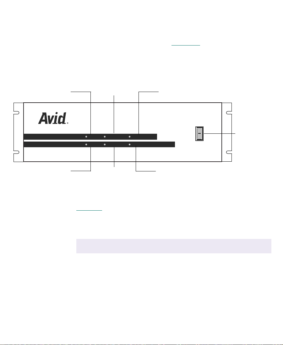
Meridien I/O Box Indicators
The Meridien I/O box provides six indicators along with a power
switch on the front of the box (see Figure 1-1
Meridien I/O box, the indicators will turn on and off as it goes
through its power-on self-test (POST). After the POST, the 48 kHz and
POWER indicators remain on.
44.1 kHz AUDIO SYNC PULL DOWN
). When you turn on the
44.1 kHz
48 kHz
48 kHz VIDEO SYNC POWER
AUDIO SYNC
VIDEO SYNC
PULL DOWN
POWER
Figure 1-1 Meridien I/O Box Indicators
Table 1-3
lists the indicator functions.
Table 1-3 Meridien I/O Box Indicator Functions
Indicator Function
44.1 kHz
c
48 kHz The 48 kHz indicator is on when 48 kHz digital audio is
The 44.1 kHz indicator is on when 44.1 kHz digital audio
is connected to the Meridien I/O box.
Do not use 44.1-kHz digital audio. The NewsCutter
accepts and outputs only 48 kHz.
connected to the Meridien I/O box.
O
l
Power switch
19
Page 20

Table 1-3 Meridien I/O Box Indicator Functions (Continued)
Indicator Function
AUDIO SYNC The audio synchronized indicator is on when audio is
detected by the Meridien I/O box.
VIDEO SYNC The video synchronized indicator is on when video is
detected by the Meridien I/O box.
PULL DOWN
POWER The power indicator is on when the Meridien I/O box
The pulldown indicator is on when performing a telecine
film-to-tape transfer whereby 24-fps film material is
adapted to the 30-fps NTSC videotape format. Extra
pulldown fields are eliminated to achieve true 24-fps film
editing.
This function is not used in the NewsCutter.
n
power switch is in the on (I) position.
Example System Layout
Before you start to connect and install equipment for NewsCutter, set
up your system components, especially monitors and keyboards, in
positions that allow you easy access to them.
20
Page 21
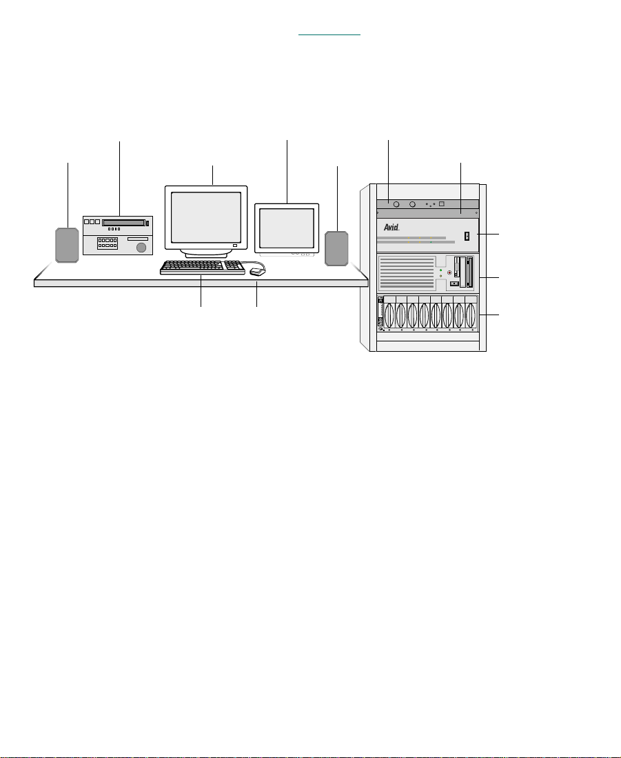
The sample layout in Figure 1-2 shows a fully configured NewsCutter
system, including a UI monitor, Playback monitor, video deck, Avid
Meridien I/O box, MediaDock, speakers, and amplifier.
Video deck
Speaker UI monitor
Keyboard
Playback monitor
Speaker
Mouse
Amplifier
VLX
SCSI IDSCSI ID
Slots
Act
Wide
Dualbus
Fans
Pwr 2Pwr 2
Pwr 1Pwr 1
Figure 1-2 Sample NewsCutter Layout
Checking the Installation Materials
When you purchase Avid NewsCutter, you should receive the
following items in the package. Make sure you have everything before
you start.
V-LAN VLXi
PULL DOWN
44.1 kHz
AUDIO SYNC
kHz
POWER
48
VIDEO SYNC
O
Meridien I/O box
l
O
l
NewsCutter
MediaDock
• NewsCutter system
A computer with specific peripheral boards for recording, editing,
and playing back clips. Included with the computer is a keyboard
and mouse. An optional rack-slide rail kit is available for
mounting the NewsCutter in a rack.
21
Page 22

• NewsCutter application key
This copy-protection device (also called a dongle) attaches to the
parallel port on your computer. A parallel printer can be
connected to the application key if a local printer is desired.
• Meridien I/O box
In a separate package, you will find a Meridien I/O box that
connects to the NewsCutter. The Meridien I/O box provides the
video and audio interface connectors for the system.
• Audio and video cables
The TARGA 2000 board set includes a VGA interconnect (loop-
through) cable and a Meridien digital media cable that connects
the NewsCutter to the Avid Meridien I/O box.
• Serial adapter (Rosetta Stone)
A serial adapter is included for remote video deck control through
COM1 of the NewsCutter. The adapter converts the NewsCutter
RS-232 signals to RS-422.
• NewsCutter CD-ROMs (2)
One CD-ROM contains the NewsCutter application. The
NewsCutter ships from Avid with the application already loaded
on the system. If you ever need to reinstall the application, see the
Avid NewsCutter Release Notes for instructions.
The second CD-ROM provides you with a copy of the NewsCutter
application context-sensitive Help and an online version of the
printed documentation (in PDF format).
• NewsCutter documentation:
- Avid NewsCutter Setup Guide (this guide)
- Avid NewsCutter Getting Started Guide
- Avid NewsCutter Release Notes
- Avid NewsCutter Help
22
Page 23

Other items you need to supply:
• XLR cables for audio connections
• Speaker wire (or cables) to connect speakers
• Broadcast-quality BNC cables for connecting video devices
• Flat-tip and #2 Phillips-head screwdrivers should be available for
component installation, setup, or attaching an optional rackmount kit to NewsCutter
• Wrist strap (recommended for grounding when handling circuit
boards)
Rack-Mounting Kits
If you have purchased an optional rack-mount kit for the NewsCutter,
install the kit before making any connections to the NewsCutter. A
stationary rail is attached to each side of the NewsCutter and the
sliding rails are attached to the rack. The NewsCutter typically
requires five rack units. Detailed instructions for attaching the rails are
included with the kit.
The Meridien I/O box also comes with two rack-mount brackets.
Allow three rack units for the Meridien I/O box in the rack.
23
Page 24
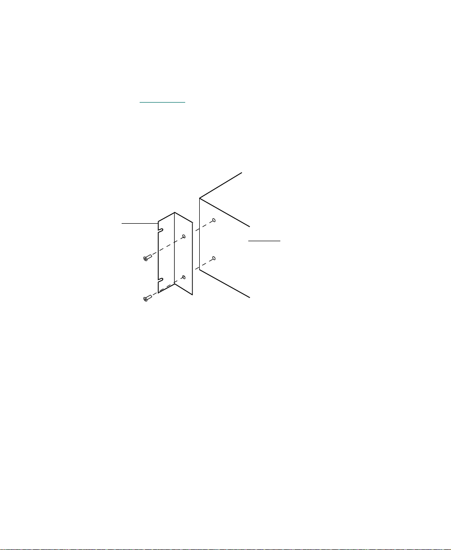
Bracket
To attach the brackets to your Meridien I/O box:
1. Locate the two brackets and four screws that come with the
Meridien I/O box.
2. Position one of the brackets so that the two holes in the bracket
line up with the holes in the side of the Meridien I/O box (see
Figure 1-3
).
3. Secure the bracket with the screws provided.
4. Repeat steps 2 and 3 for the other side.
Meridien I/O box
Figure 1-3 Meridien I/O Box
24
Page 25

CHAPTER 2
Setting Up the NewsCutter System
This chapter provides instructions for connecting the keyboard,
mouse, application key, UI monitor, and Avid Meridien I/O box to the
NewsCutter. These instruction use generic illustrations representing
the type of connector found on the back of the NewsCutter. For the
exact connector locations, see the documentation that is provided by
the computer manufacturer.
Install the NewsCutter into your rack before you connect any cables
(see Chapter 1 for more rack-mounting information).
Connecting the Keyboard and Mouse
The NewsCutter uses industry-standard PS/2-style keyboard and
mouse input devices.
25
Page 26
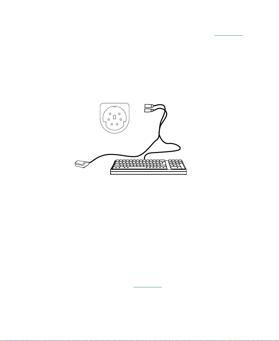
To connect your keyboard and mouse:
1. Plug the keyboard and mouse cables into the PS/2-style
connectors on the back of the NewsCutter (see Figure 2-1
The PS/2-style connectors have keyboard and mouse icons beside
the connectors or are color coded.
).
n
PS/2 connector
Use PS/2-style extension cables with the keyboard and mouse when the
NewsCutter is rack-mounted.
Figure 2-1 Keyboard and Mouse Connection
Installing the Application Key
The application key (also called a dongle) is a copy-protection device.
Without the application key, the NewsCutter application will not run.
KeyboardMouse
To install the application key:
1. Plug the application key into the parallel port on the back of your
NewsCutter (see Figure 2-2
2. Secure the application key to the connector with the attached
screws.
26
).
Page 27
c
Parallel port connector
Do not overtighten the application key screws.
Application key
Figure 2-2 Application Key Connection
n
A local parallel printer can still be used even though the application key is
connected to the parallel port. The application key allows the printer signals
to pass to and from the printer.
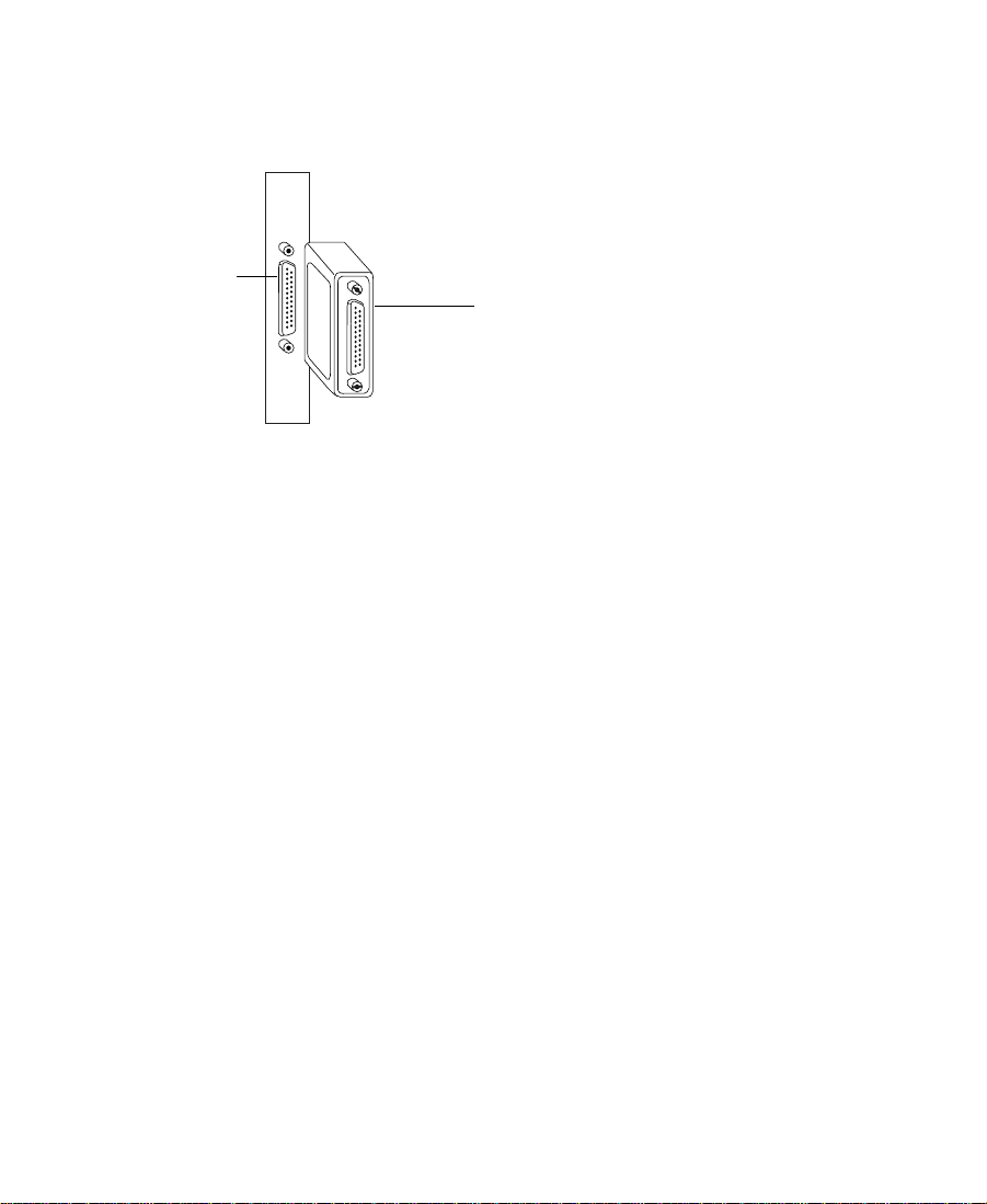
Connecting the VGA Interconnect Cable
The video graphics array (VGA) interconnect cable has three
connectors. This cable is used to carry the video output from your
computer’s VGA board to the TARGA 2000 video board. The VGA
interconnect cable also connects to your VGA monitor cable (that
comes with your monitor).
27
Page 28
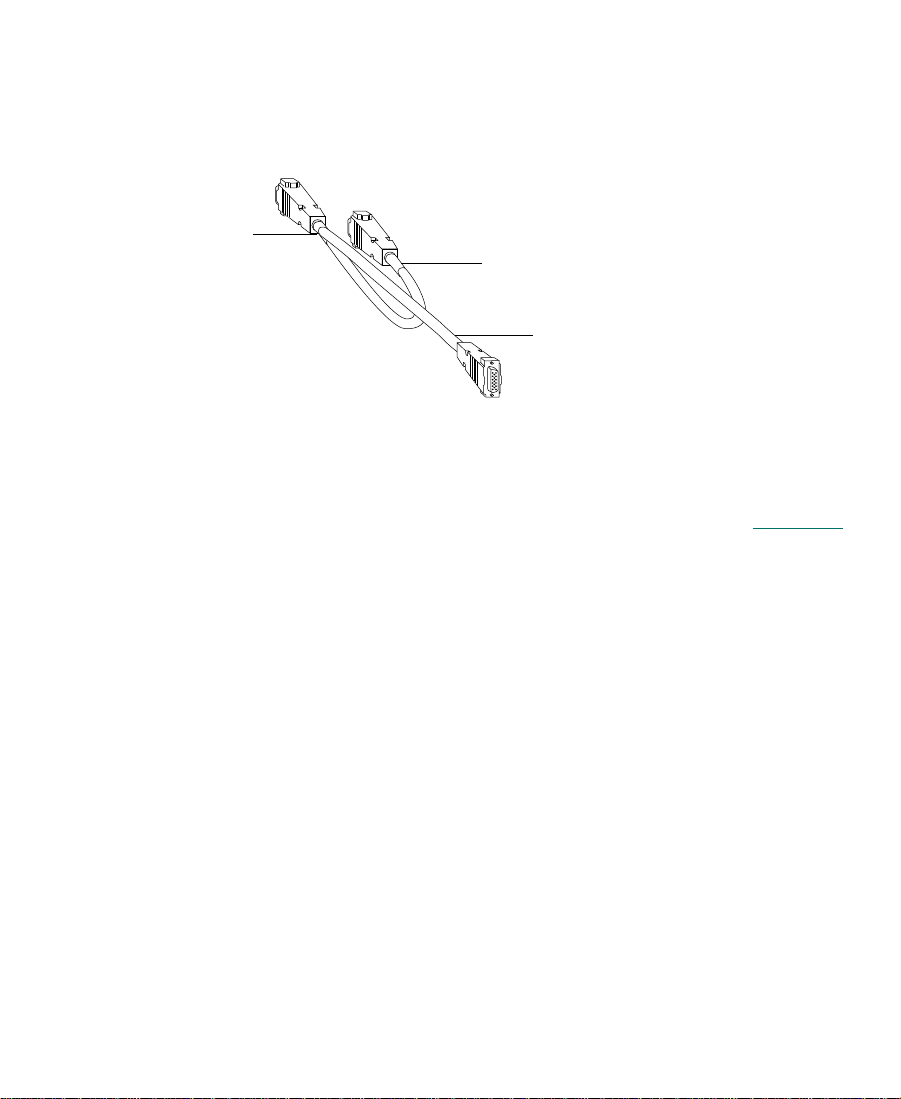
TARGA 2000 label
To connect to your VGA monitor:
1. Locate the VGA interconnect cable (also known as a VGA “loop-
through” cable), labeled CA-206.
VGA label
Monitor label
Figure 2-3 VGA Interconnect Cable
2. Connect the 15-pin male connector (labeled TARGA 2000) to the
VGA connector on the TARGA 2000 video board (see Figure 2-4
3. Continuing with the VGA interconnect cable, connect the 15-pin
male connector (labeled VGA) to the VGA connector on the
standard video board.
).
28
Page 29
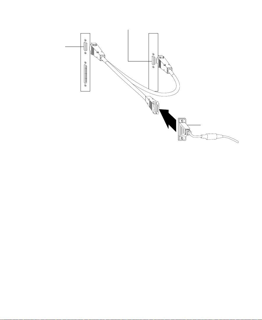
VGA connector on the
TARGA 2000 video board
VGA connector on the
standard video board
Monitor cable
Figure 2-4 VGA Interconnect Cable Connections
4. Connect the 15-pin female connector (labeled Monitor) to the VGA
monitor cable (provided with the monitor).
n
Use a VGA-style extension cable with the UI monitor when the NewsCutter
is rack-mounted.
5. Make sure that the other 15-pin end of the VGA monitor cable is
connected to the back of the monitor . (For more information, check
the documentation that comes with your monitor.)
29
Page 30

Connecting NewsCutter to the Meridien I/O Box
All audio and video interfacing with the NewsCutter is done through
a Meridien digital media cable. This Meridien digital media cable
connects the Meridien I/O box to the NewsCutter. The Meridien I/O
box is designed to provide a convenient way to attach many cables to
the NewsCutter system.
To attach the cable:
1. Locate the Meridien digital media cable. This 6-foot (1.8-meter)
cable ships with the NewsCutter.
n
c
An optional 50-foot cable can be ordered from Avid.
2. Plug one end of the Meridien digital media cable into the
connector labeled SYSTEM IN/OUT on the Meridien I/O box.
Tighten the screws on the cable to secure it in place (see
Figure 2-5
Do not overtighten the digital media cable screws.
3. Attach the other end of the system Meridien digital media cable to
the TARGA 2000 video board M port connector on the
NewsCutter. Tighten the screws on the cable to secure it in place
(see Figure 2-5
).
).
30
Page 31

4. Plug the power cords into the power connector on both the
NewsCutter and the Meridien I/O box. Plug the other end of each
power cord into an ac power source.
Avid Meridien I/O box
Power cord
TARGA 2000
video board
M port connector
on the NewsCutter
Figure 2-5 Connection Between the NewsCutter and
Meridien I/O Box
Avid MediaDrive Connection
This section provides information about Avid-approved drives and
points out some important areas you need to be aware of if you are
planning to use non-Avid drives.
Do not record your media to the internal system drive. Use external
SCSI hard drives to store your media. Avid offers external drives that
have been qualified for video and audio media, referred to as
MediaDrives. MediaDrives can also store nonmedia files.
SYSTEM IN/OUT connector
Meridien digital media cable
31
Page 32

n
Avid recommends that you purchase a 30-inch (76.2-cm) SCSI cable for
connecting the first SCSI drive to the system. An active SCSI terminator is
also required for terminating the last drive in the chain.
Connect the MediaDrives according to the documentation that comes
with the drives. Avid-recommended drives provide the following
documentation:
• Avid rS MediaDrive Setup and User’s Guide ships with the
individual MediaDrives.
• Avid MediaDock LVD Setup and User’s Guide ships with the media
docking station.
The NewsCutter provides a 68-pin, high-density SCSI connector. You
can have more than one MediaDrive attached to the NewsCutter.
When attaching multiple SCSI drives, assign the SCSI IDs from 0 to 6
and 8 to 15. The last drive in the chain must be terminated. Figure 2-6
illustrates the SCSI connection.
SCSI connector
n
Typically, SCSI ID 0 is assigned to the internal SCSI drive if your
NewsCutter has an internal SCSI drive installed. For specific information
about the internal SCSI device IDs, see the manufacturer’s documentation.
SCSI cable to
MediaDrives
Figure 2-6 MediaDrive SCSI Connector
32
Page 33

T urn on the external MediaDrives befor e turning on your NewsCutter.
Allow approximately 10 to 15 seconds for the MediaDrive to complete
its self-test.
c
n
Turning on your NewsCutter before each MediaDrive completes its
self-test could cause the system to ignore the drive.
Before you can store files on the MediaDrives, you must format and
partition them with the Windows NT operating system (see the
documentation that comes with your drive). The NewsCutter
application uses the NT File System (NTFS).
If you have more than one hard disk drive and performance is a high priority,
you can use striping across multiple external hard drives. Striping increases
the read and write speed. For more information, see your Windows NT
documentation.
Evaluating Drive Types
The quality of your external drive where you store media affects the
end results of your video product. For best performance, use Avidapproved drives. Storage components (including terminators, power
supplies, and cables) that are integrated into Avid drives are fully
tested and certified against stringent criteria.
Avid recognizes the possibility of using non-Avid drives. However,
Avid cannot ensure the viability of third-party solutions or provide
support for them.
n
If you are using non-Avid drives to store your media, in the General Settings
dialog box, you must deselect Drive Filtering Based on Resolution.
To record and play back the media properly, you must have media
storage devices with:
• A SCSI-II compliant interface, fast and wide, 20-MB-per-second
minimum controller bus transfer rate
33
Page 34

• A sustained SCSI transfer rate of 4.5 to 6.5 MB per second
• An average seek time of 12.5 milliseconds or less (including
controller overhead without disconnect)
• 1 MB or greater on-board cache (memory)
• Impedance-matched internal and external cabling
• Active termination
• Appropriate-size power supplies for continuous use
• Regulatory approvals (CSA, FCC, TÜV, UL)
Data Rate Calculations
Use Table 2-1 to determine how many minutes of audio and video you
can store on your MediaDrive. (These numbers are approximate.) At a
DV25 resolution, a 9-GB drive stores about 40 to 45 minutes of media,
and an 18-GB drive stores about 80 to 90 minutes of media.
n
Calculations include a 20 percent system overhead factor.
Table 2-1 DV25 Data Rate Storage Calculations
Megabytes
per Second
4.4 266.7 4.6
Megabytes
per Minute
34
Minutes
per Gigabyte
Page 35

Optional NewsCutter Connections
The NewsCutter can work as a standalone system or as part of a
broadcast network. The following connections are necessary if you are
planing on transferring media files over a network (using Avid
Transfer Tool software) or sending media out to a playback device
over a Fibre Channel network.
Network Configuration
NewsCutter systems include an RJ-45 Ethernet network connector.
Avid recommends that you use a category-5 unshielded twisted pair
(UTP) cable when connecting the NewsCutter to a network. For more
information on the installed network interface, see the documentation
provided by the computer manufacturer.
Fibre Channel Workgroup Configuration
An optional Fibre Channel connection kit is available for the
NewsCutter. If you are installing a Fibre Channel connection kit,
follow the instructions provided by the computer manufacturer for
removing the cover and installing an expansion board. Chapter 6
provides more information on setting up a Fibre Channel network by
using a playback device.
35
Page 36

CHAPTER 3
Connecting Audio and Video Devices
This chapter describes the connection between the Avid Meridien I/O
box and the audio and video devices. Install the Meridien I/O box into
your rack before you connect any cables (see Chapter 1 for more rackmounting information).
The Meridien I/O box communicates with the NewsCutter through
the Meridien digital media cable. This cable provides all the audio,
video, timecode, and reference signals to the NewsCutter. The
connection between the NewsCutter and Meridien I/O box is
described in Chapter 2.
Avid Meridien I/O Box Connections
The audio and video interact with the NewsCutter through the Avid
Meridien I/O box. The Meridien I/O box provides connectors for all
the standard audio and video input and output signals. The
connections to the Meridien I/O box will vary, depending upon your
deck and type of audio and video signals used.
36
Page 37

Audio Interface Connections
The Meridien I/O box provides the following analog and digital
connections:
• Two analog audio channels; two sets of input and output
connectors.
• One analog microphone connector; accepts powered or phantom
power microphones. Choose the audio input setting in the Record
tool to match your type of microphone.
• One digital Audio Engineering Society/European Broadcasting
Union (AES/EBU) audio channel; one set of input and output
connectors. Each AES/EBU channel has left and right channel
information. AES/EBU is a format used with professional digital
audio equipment (for example, audio from a videotape or CD).
• One digital Sony/Philips
audio channel; one set of input and output RCA
Some digital audiotapes (DATs) found in consumer digital audio
equipment use S/PDIF.
®
Digital Interface Format (S/PDIF)
®
connectors.
n
The NewsCutter system accepts and outputs only 48-kHz digital audio. Do
not use 44.1-kHz digital audio.
The audio interface usually is connected to an amplifier with speakers
for monitoring audio during recording and playback. Pay careful
attention to the audio levels while you are recording. Use a mixer or
amplifier to control the audio levels.
37
Page 38

Figure 3-1 shows the audio hardware connections.
All audio cables are customer supplied.
Speakers
Microphone input
Audio amplifier
Audio channel inputs
Audio output to deck or
other audio destination
Audio channel outputs
Speakers can connect directly or through an amplifier.
(Speakers and amplifier are optional.)
Powered
speakers
AES/EBU digital I/O
Phono (RCA) jacks
for S/PDIF digital I/O
Avid Meridien I/O box
Audio input from deck or
other audio source
Figure 3-1 Audio I/O Connections
38
Page 39

Video Interface Connections
Figure 3-2 shows the connectors used to connect the customer-
supplied Playback monitor and video deck to the Avid Meridien I/O
box. These connectors are used for video input and output from decks,
satellite feeds, or routers. A customer-supplied Playback monitor
displays incoming video when the system is recording or edited
material during playback. These analog video connections can be
either composite or component. See “Serial Digital Interface
Connections” on page 40 if you are connecting digital video to the
Meridien I/O box.
The video connections also require a reference signal (black burst
generator or house clock) to lock audio and video sampling together to
keep video and audio synchronized. See “Connecting the Reference
Signal” on page 41.
All video cables are customer supplied.
Component video input connections
(from deck, router, or satellite feed)
Composite video input connection
(from deck, router, or satellite feed)
S-Video input connection
(from deck, router, or satellite feed)
Figure 3-2 Video I/O Connections
Component video output connections
(to deck, router, or monitor)
Avid Meridien I/O box
S-Video output connection
(to deck or monitor)
Three composite video output connectors
(to deck, router, or monitor)
39
Page 40

Serial Digital Interface Connections
The serial digital interface board is optional. If you need to install the
optional serial digital interface board, see “Serial Digital Interface
Board Installation” on page 91. Figure 3-3 shows the BNC connectors
used to connect the serial digital video to the Avid Meridien I/O box.
These connectors are used for video input and output from decks,
satellite feeds, or routers.
The video connections also require a reference signal (black burst
generator or house clock) to lock audio and video sampling together to
keep video and audio synchronized. See “Connecting the Reference
Signal” on page 41.
All video cables are customer supplied.
Avid Meridien I/O box
Serial video input connection
(from deck, router, or satellite feed)
Three serial video output connectors
(to deck, router, or monitor)
Figure 3-3 Serial Digital Video I/O Connections
40
Page 41

Connecting the Reference Signal
All broadcast systems require an analog video reference signal. The
video reference signal must be provided to several of the system
components and must meet standard NTSC or PAL specifications.
The video reference signal can be a black burst generator or the house
black reference signal (see Figure 3-4
the Avid Meridien I/O box, V-LAN VLXi
). The reference signal connects to
controller, and deck.
All cables are customer supplied.
Black burst generator
or house referencevideo source
Video reference output
to REF connector
Figure 3-4 Reference Signal Connections
Video reference output
to video deck
BB3BB1 BB2
V-LANVLXi
SERIAL PARALLEL REF LAN CF
Avid Meridien I/O box
Video reference output
to REF connector
Terminator
TIMECODE A
SERIAL A SERIAL B
VLX TRANSMITTER VLX 2R DUAL RECEIVER
IN INOUT OUT
TIMECODE B
Video deck
Optional
AC
41
Page 42

Controlling a Video Deck
You can control up to two video decks remotely by using serial
connections between the NewsCutter and the video deck. This serial
connection requires an RS-232 to RS-422 cable adapter for each video
deck connected to the NewsCutter. A serial adapter kit, called the
Rosetta Stone, is provided with the NewsCutter. The serial adapter kit
contains:
• An RS-232 to RS-422 serial adapter
• Two serial cables; male 9-pin connectors at both ends
To video deck
n
If you need to connect and control more than two video decks, see
“Connecting a V-LAN VLXi Controller and GPI Devices” on page 43.
To connect the remote control:
1. Locate the serial adapter kit.
2. Attach one end of the first 9-pin cable to the end of the serial
adapter labeled RS-232 (see Figure 3-5
3. Attach the other end of the first 9-pin cable to the NewsCutter
COM1 serial port (see Figure 3-6
Serial adapter RS-232 connectionRS-422 connection
LEDs
Figure 3-5 Video Deck Control Cabling
4. Attach one end of the second 9-pin cable to the end of the serial
adapter labeled RS-422.
).
).
To NewsCutter
42
Page 43

5. Attach the other end of the second 9-pin cable to the remote serial
port of the video deck.
6. Set the video deck’s Remote mode switch to Remote.
n
If the LEDs on the serial adapter do not light when the connections are
completed with the equipment turned on, the serial adapter is connected
backward. Before the remote control becomes functional, you must also choose
the COM port in the Deck Configuration window of the NewsCutter
application (see the NewsCutter Help for more information).
Connecting a V-LAN VLXi Controller and GPI Devices
The NewsCutter can control multiple video decks through a video
local area network (V-LAN) VLXi deck controller. Use a generalpurpose interface (GPI) connected to the V -LAN to trigger functions in
the NewsCutter.
Video Local Area Network
The V-LAN VLXi shown in Figure 3-6 consists of one V-LAN
transmitter and a dual V -LAN VLXi receiver. The receiver contains
two deck controllers. Both the transmitter and receiver are
internally linked. The V-LAN VLXi connects to the NewsCutter
through a direct serial connection.
Each V-LAN VLXi supports two video decks. Daisy-chain
multiple V-LAN VLXi units together if you need to add more
video decks.
General-Purpose Interface
The VLXi-GT contains six programmable GPI input and output
terminals. The GPI input terminal can be configured to trigger the
NewsCutter to Play, Record, Cue, and Stop. You can configure the
GPI output terminal to provide Stop, Record, and Play status. For
information on configuring the GPI in the NewsCutter
application, search for GPI in the Help.
43
Page 44

Assign the VLXi-GT to V-LAN node addresses 16 through 19.
LAN connections of more than 50 feet must have a terminator. For
more information, see the Videomedia VLXi User’s Guide.
The V-LAN VLXi deck controller and VLXi-GT connect to the
NewsCutter as shown in Figure 3-6
Six GPI input and output terminals
IN OUT1IN OUT2IN OUT3IN OUT4IN OUT5IN OUT
SERIAL LAN CF
V-LAN connection
.
All cables are customer supplied.
VLXi-GT (GPI)
6
AC
Terminator
(required when cable length
is more than 50 feet)
VLXi transmitter
serial input
SERIAL PARALLEL REF LAN CF
VLX TRANSMITTER VLX 2R DUAL RECEIVER
TIMECODE A
SERIAL A SERIAL B
IN INOUT OUT
TIMECODE B
Serial connection
to deck remote
Serial cable to RS-232 COM1 port
on the NewsCutter
Figure 3-6 V-LAN VLX
i
Deck Control
AC
Video deck
V-LAN VLXi
44
Page 45

Master Clock Connection
When you are controlling the video deck through a serial remote
control or a V-LAN VLXi controller, the deck timecode is utilized in
the application. Avid strongly recommends synchronizing the
NewsCutter to the house master clock (SMPTE for NTSC, and EBU for
PAL) when using a satellite feed or manually controlling a video deck.
The house master clock connects to the Timecode IN connector on the
Avid Meridien I/O box (see Figure 3-7
throughout the Avid NewsCutter system.
). This timecode is used
Timecode IN
connector
Figure 3-7 Timecode Connections
45
Timecode OUT
connector
(not functional)
Page 46

CHAPTER 4
Running the System Diagnostics
After you have set up the Avid NewsCutter system, test the system to
make sure that the Avid components and peripheral boards are
functioning properly. Avid supplies a system diagnostics program
(Avid System Test Pro) to help you verify that the Avid TARGA 2000
board set and the Avid Meridien I/O box are working properly. In
addition, a storage exerciser (Avid StorEx) is supplied for testing the
MediaDrives.
This chapter provides enough information to run the diagnostics. Use
the Help provided within the diagnostics for more information about
the function of specific buttons and windows.
To start the Help, start the Avid System Test Pro application and
choose Help from the Help menu. The Help Topics window opens.
Double-click a book icon in the Help window to display the topics.
The application also provides context-sensitive Help. While the
diagnostic window is active, press F1 to display information about
that window.
46
Page 47

The Avid System Test Pro reads the Meridien I/O box default state
when you start the diagnostics. These defaults are used during the
diagnostics. An example default state could be NTSC mode,
Composite In, and Component Out. To change the default state of the
Meridien I/O box, run the Avid Video I/O Utility application.
Turning On the System
After you have connected the keyboard, mouse, application key,
monitors, MediaDrives, and Meridien I/O box, you should turn on the
system to make sure the system starts properly before you start the
NewsCutter software.
To turn on the system:
1. Make sure all devices are properly plugged into a surge protector
or wall outlet.
2. Turn on the UI monitor, Meridien I/O box, and MediaDrives.
3. Turn on the NewsCutter by pressing the power switch to the on (I)
position on the front of the unit.
The system starts. System-specific information is displayed on the
UI monitor.
4. Select Windows NT Workstation 4.0 when asked to select the
operating system.
Avid System Test Pro
The Avid System Test Pro diagnostics are a set of tests that check the
Avid TARGA 2000 video board set and the Avid Meridien I/O box.
Run these diagnostics before you begin editing with your NewsCutter
system. Avid System Test Pro is divided into two separate test suites:
47
Page 48

• Standard — Tests all the Avid board sets with no intervention
needed by the user
• External/User Interaction — Tests the I/O portions of the board sets
and needs user intervention such as connecting cables and
answering questions in a dialog box
Avid System Test Pro contains Help that provides information on each
button, window, and test. This section provides:
• A brief explanation of the user interface
• A procedure for running standalone diagnostics
• Cable connections needed for the interactive portion of the
diagnostics
• A procedure for running interactive diagnostics
n
You should read this section completely before you attempt to run the
diagnostics.
Starting Avid System Test Pro
To start Avid System Test Pro:
1. Close all open applications.
2. Click the Start button, point to Programs, point to Avid, point to
Utilities, and click Avid System Test Pro.
Avid System Test Pro starts, and a dialog box appears.
3. Click OK.
The main window opens. To exit the Avid System Test Pro
diagnostics, choose Quit from the File menu.
48
Page 49

Quick Start Dialog Box
The Avid System Test Pro Quick Start dialog box appears when you
start the Avid System Test Pro diagnostic program (see Figure 4-1).
This dialog box tells you what you need to do to start testing the
standard set of diagnostics using all test program defaults. The
defaults include the use of NTSC video.
Figure 4-1 Avid System Test Pro Quick Start Dialog Box
Understanding the Main Window
The Avid System Test Pro for NewsCutter window (see Figure 4-2)
appears the first time you run the diagnostics. This window contains
the test selections, buttons needed to start and stop the diagnostics,
and indicators for test status.
Pause button Stop button
Start button
Test suite tabs
Test tree
Expansion
button
Figure 4-2 Avid System Test Pro for NewsCutter Window
49
Toolbar
Item name
Item check box
Item status
System status
Page 50

The Avid System Test Pro for NewsCutter window contains:
• Toolbar — A VCR-like user interface that provides control over
running the diagnostics. When you first start the diagnostics, only
the Start button in the toolbar is active.
• Test suite tabs — Allow the user to select the Standard or
External/User Interaction test suite to run. Each suite has a status
indicator that provides status for each suite selected.
- Standard test suite contains tests that run without special
cabling or user interaction.
- External/User Interaction suite contains tests that requir e user
interaction and special cabling. See “Running the External/
User Interaction Diagnostics Suite” on page 53 for
information on how to cable the system for these tests.
• Test tree — A section of the window that contains expansion
buttons, item names, item check boxes, and item status.
• Expansion button — Clicking an expansion button (+) switches
the level of detail for a given item. For example, clicking + shows
the groups within the item.
• Item name — The name of the board being tested or the test name
under that board if the item is expanded.
• Item check box — Selects the item for testing. When the check box
contains an X, the item is selected for testing. By default, all tests
associated with the Standard suite are selected when you first run
the diagnostic program from the desktop. Items are deselected
when the box is empty.
• Item status — Provides status of each test (see the Help for a
complete explanation).
• System status — Displays the pass or fail status of the entire
system.
You should run both suites of Avid System Test Pro diagnostics to
ensure that the NewsCutter system is functioning properly. You
should run the Standard suite first and then the External/User
Interaction suite if the Standard suite passes.
50
Page 51

Understanding the Avid System Test Preferences Window
The A vid System Test Preferences window opens when you choose Set
Preferences from the Options menu. The Avid System Test Preferences
window controls the way testing occurs. The window has two tabs:
Test Control tab and Video Subsystem tab.
Test Control Tab
The Test Control tab allows you to select the manner in which errors
are to be handled and how many times you want to repeat the test (see
Figure 4-3
).
Figure 4-3 Avid System Test Preferences Window
— Test Control Tab
Video Subsystem Tab
The Video Subsystem tab (see Figure 4-4
default video standard (NTSC, NTSCj, or PAL) of the Meridien I/O
box. The Meridien I/O box defaults to NTSC in the United States. If
the default is set to NTSC and you want to test the PAL functions, you
must change the video standard to PAL and restart the diagnostic (the
settings are looked at only during the diagnostic startup).
51
) allows you to override the
Page 52

Figure 4-4 Avid System Test Preferences Window
— Video Subsystem Tab
Running the Standard Diagnostics Suite
To run the Standard diagnostics suite:
1. Start the diagnostics as described in “Starting Avid System Test
Pro” on page 48.
The Avid System Test Pro Quick Start dialog box appears,
explaining how to run the Standard diagnostics using default
settings.
2. Click OK.
3. Click the Start button in the toolbar in the main window.
The Standard diagnostics run with status shown in the Item status
boxes in the main window.
4. Do one of the following:
• If the tests pass, continue testing at “Running the External/
User Interaction Diagnostics Suite” on page 53.
• If any test fails, the Error Log window opens, showing which
board failed the test.
52
Page 53

If this is the first time the tests have failed, see Chapter 5,
“Troubleshooting,” for possible solutions to the problem.
If you have tried the solutions in Chapter 5 and the
diagnostics still fail, contact your Avid Reseller.
Running the External/User Interaction Diagnostics Suite
The External/User Interaction diagnostics suite tests the following
assemblies:
• TARGA 2000 board set — Interactive test that requires you to
respond to pop-up dialog boxes as they appear.
• Meridien video I/O board — External test that requires you to
cable selected inputs to selected outputs before you run the tests.
The test might be NTSC, NTSCj, or PAL, depending upon the
selection in the Avid System Test Preferences window.
• Meridien audio I/O board — External test that requires you to
cable the channel 1 and 2 inputs to the outputs before you run the
tests.
All External/User Interaction tests displayed under these items are
deselected by default, and you must select each test to run them.
To cable the boards in the Meridien I/O box to run the interactive
tests, locate the following cables (all cables are customer supplied):
• Audio cable — Two male XLR connectors on one end and two
female XLR connectors at the other or two individual audio cables.
Avid recommends a Beldon 8451 audio cable or equivalent.
• Component video cable — Three BNC connectors at both ends of
the cable or three individual BNC video cables. Avid recommends
a Beldon 8281 video cable with 75-ohm video connectors or
equivalent.
• Composite video cable — One BNC connector at each end.
• S-video cable — One 6-pin, S-video connector at each end.
53
Page 54

Cable the Meridien I/O box as described in the following section, and
then see “Running the External Tests” on page 58 for instructions.
External Diagnostics Audio Cabling
Connect the audio channel inputs to the audio channel outputs on the
audio I/O board with the audio test cable (see Figure 4-5
1. Attach CHAN 1 OUT to the CHAN 1 IN.
2. Attach CHAN 2 OUT to the CHAN 2 IN.
).
AUDIO IN
COMPONENT
COMPOSITE
IN
ININ
IN
MIC CHAN 1
Y
COMPOSITE
REF
R-Y B-Y
-10
CHAN 2
CHAN 1
Y
R-Y
S-VIDEO
OUT 1
OUT 2
Figure 4-5 Audio Test External Cabling
External Diagnostics Component Video Cabling
Connect the component video cable to the video I/O board as shown
in Figure 4-6
1. Connect one end of the cable (using the three BNC connectors) to
the COMPONENT OUT on the video I/O board as follows:
a. Attach one green wire BNC connector to the connector labeled
b. Attach one red wire BNC connector to the connector labeled
c. Attach one blue wire BNC connector to the connector labeled
.
Y OUT.
R-Y OUT.
B-Y OUT.
AUDIO OUT
-10
GAIN 1
+4
OUT
B-Y
S-VIDEO
OUT 3
AES / EBU
GAIN 2
CHAN 2
OUT 1 OUT 2 OUT 3IN
DIGITAL VIDEO
SYSTEM
OUT
IN / OUT
S / PDIF
IN
OUT
IN
OUT
LTC
SLAVE CLOCK
IN
OUT
OUT
54
Page 55

AUDIO IN
MIC CHAN 1
IN
ININ
COMPONENT
Y
R-Y B-Y
IN
COMPOSITE
S-VIDEO
COMPOSITE
REF
Figure 4-6 Component Video External Cabling
2. Connect the other end of the cable (using the three BNC
connectors) to the COMPONENT IN on the video I/O board as
follows:
a. Attach the green wire BNC connector to the connector labeled
Y IN.
b. Attach the red wire BNC connector to the connector labeled R-
Y IN.
c. Attach the blue wire BNC connector to the connector labeled
B-Y IN.
External Diagnostics Composite Video Cabling
AUDIO OUT
-10
-10
GAIN 1
CHAN 2
+4
CHAN 1
OUT
B-Y
Y
R-Y
S-VIDEO
OUT 1
OUT 3
OUT 2
AES / EBU
GAIN 2
CHAN 2
OUT 1 OUT 2 OUT 3IN
DIGITAL VIDEO
SYSTEM
OUT
IN / OUT
S / PDIF
IN
OUT
IN
OUT
LTC
SLAVE CLOCK
IN
OUT
OUT
Connect the composite video cable to the video I/O board as shown in
Figure 4-7.
1. Connect one end of the cable to COMPOSITE IN on the video
board.
55
Page 56

2. Connect the other end of the cable to COMPOSITE OUT 1 on the
video I/O board.
AUDIO IN
COMPONENT
COMPOSITE
IN
ININ
IN
MIC CHAN 1
Y
COMPOSITE
REF
R-Y B-Y
-10
CHAN 2
CHAN 1
Y
R-Y
S-VIDEO
OUT 1
OUT 2
Figure 4-7 Composite Video External Cabling
To test OUT 2 and OUT 3, move the output end of the cable to the untested
n
output and run the test again for each one.
External Diagnostics Serial Digital Video Cabling
Connect the serial digital cable to the serial digital interface board (if
installed) as shown in Figure 4-8
n
The serial digital interface board is optional and might not be installed in
your Avid Meridien I/O box.
1. Connect one end of the cable to IN on the DIGITAL VIDEO
portion of the serial digital interface board.
AUDIO OUT
-10
GAIN 1
+4
OUT
B-Y
S-VIDEO
OUT 3
AES / EBU
GAIN 2
CHAN 2
OUT 1 OUT 2 OUT 3IN
DIGITAL VIDEO
SYSTEM
OUT
IN / OUT
S / PDIF
IN
OUT
IN
OUT
LTC
SLAVE CLOCK
IN
OUT
OUT
.
56
Page 57

2. Connect the other end of the cable to OUT 1 on the DIGITAL
VIDEO portion of serial digital interface board.
AUDIO IN
Figure 4-8 Serial Digital Video External Cabling
To test OUT 2 and OUT 3, move the output end of the cable to the untested
n
output and run the test again for each one.
External Diagnostics S-Video Cabling
Connect the S-video cable to the video I/O board as shown in
Figure 4-9
1. Connect one end of the S-video cable to S-VIDEO IN on the video
2. Connect the other end of the cable to S-VIDEO OUT on the video
.
I/O board.
I/O board.
COMPONENT
COMPOSITE
IN
IN
MIC CHAN 1
ININ
Y
REF
COMPOSITE
R-Y B-Y
AUDIO OUT
-10
-10
GAIN 1
CHAN 2
S-VIDEO
+4
CHAN 1
OUT
B-Y
Y
R-Y
S-VIDEO
OUT 1
OUT 3
OUT 2
AES / EBU
GAIN 2
CHAN 2
OUT 1 OUT 2 OUT 3IN
DIGITAL VIDEO
SYSTEM
OUT
IN / OUT
S / PDIF
IN
OUT
IN
OUT
LTC
SLAVE CLOCK
IN
OUT
OUT
AUDIO IN
MIC CHAN 1
CHAN 2
IN
ININ
Y
COMPONENT
R-Y B-Y
IN
COMPOSITE
S-VIDEO
COMPOSITE
REF
AUDIO OUT
-10
-10
GAIN 1
GAIN 2
+4
CHAN 1
Y
R-Y
OUT 1
OUT 2
CHAN 2
OUT 1 OUT 2 OUT 3IN
OUT
B-Y
DIGITAL VIDEO
OUT
S-VIDEO
OUT 3
Figure 4-9 S-Video External Cabling
57
AES / EBU
S / PDIF
IN
OUT
IN
OUT
LTC
SLAVE CLOCK
SYSTEM
IN / OUT
IN
OUT
OUT
Page 58

Running the External Tests
To run the External/User Interaction tests:
1. Start the diagnostics as described in “Starting Avid System Test
Pro” on page 48.
The Avid System Test Pro Quick Start dialog box appears,
explaining how to run the Standard diagnostics by using the
default settings.
2. Click OK.
3. Click the External/User Interaction tab in the main window.
4. Loop back the Meridien I/O box connectors as explained in the
previous sections.
5. Click the Start button in the toolbar in the main window.
The External/User Interaction diagnostics run with the status
shown in the Item status boxes in the main window.
6. Answer any pop-up dialog box questions that might appear.
7. Do one of the following:
• If the tests pass, choose Quit from the File menu and consider
that your Avid system is working properly.
• If any test fails, the Error Log window opens, showing which
board failed the test. First check the setup instructions in
Chapter 2 and Chapter 3 to make sure the system is set up
properly. Then, see the Error Condition topic in the diagnostic
Help for possible solutions to the problem.
If you have tried the solutions and the diagnostics still fail,
contact your Avid Reseller.
58
Page 59

Understanding the Error Log Window
When an error is detected during a test, a dialog box appears,
informing you an error has occurred. Choose Error Log from the
Window menu (see Figure 4-10
that have occurred since the application started or since the error log
was cleared. Each entry lists the failing board, the failing test, and the
time of the failure. If you double-click on a failure, a more detailed
error window opens.
Figure 4-10 Error Log Window
The information in the Error Log window can be saved in text (.TXT)
format by choosing Save Error Log from the File menu. Once the error
log has been saved, you can open the saved file with any text editing
application and print it.
) to display information on all errors
Avid StorEx
Avid StorEx is a general-purpose, hard-drive exerciser program that
verifies the operation of SCSI hard drives connected to a SCSI
accelerator board or a Fibre Channel (F/C), PCI-based Avid system.
The program also provides test status information that is helpful for
troubleshooting a drive problem. Your local Avid Reseller might
instruct you to use StorEx as part of the process of troubleshooting a
problem with a hard drive.
StorEx requires a working Avid system in order to function properly.
The F/C controller and the SCSI accelerator board must be functioning
and be able to accept commands and return results.
59
Page 60

StorEx is installed with the NewsCutter software. StorEx is located on
the system hard drive in the C:\Program Files\Avid\Utilities\StorEx
folder.
Running Avid StorEx
Before you start Avid StorEx, check to see if the F/C drive enclosure is
set to ID 0. It must be set to ID 0 for StorEx to run properly.
To run Avid StorEx:
1. Quit all applications that are running on your NewsCutter.
2. Click the Start button, point to Programs, point to Avid, point to
Utilities, and then click Avid StorEx.
The Avid StorEx Disk Test window opens.
3. Select the devices you want to test by clicking the check box for
each device in the Test display (see “Test Display” on page 63
4. Choose Preferences from the Options menu, and select the
preferences you need for the selected tests.
).
c
Avid suggests that you use the default settings in the Preferences
window. You should not choose any destructive tests without first
talking to your Avid Reseller.
5. Start the testing by clicking the Start button in the toolbar (see
“Toolbar” on page 62
(see “Menus” on page 62).
6. When the test is complete, you can view the status in the Console
display (see “Console Display” on page 64
7. If you have any failures, contact your Avid Reseller.
) or by choosing Start from the Testing menu
).
60
Page 61

Avid StorEx Disk Test Window
The Avid StorEx Disk Test window provides information on the
devices available for testing and the results of each test (see
Menu
Toolbar
Test
display
Console
display
Figure 4-11
).
Figure 4-11 Avid StorEx Disk Test Window
The window is divided into four areas:
•Menu
• Toolbar
• Test display
• Console display
61
Page 62

Menus
The StorEx menus are at the top of the display and provide the
following functions:
• File — Allows you to quit the program by choosing Exit from the
File menu.
• View — Allows you to define what you want to see in the Console
display. The available choices are:
- Toolbar
- Tests (also select by pressing and holding Alt+1)
- Console (also select by pressing and holding Alt+2)
• Testing — Allows you to control the testing. The available choices
are:
- Start
- Pause
-Stop
- Default Tests
• Options — Allows you to open the Preferences window (see “Test
Preferences Window” on page 64) and to define the type of error
that causes the test to stop:
Toolbar
- Stop On Hard Error
- Stop On Any Error
• Help — Lists the StorEx revision level.
The toolbar is a VCR-like user interface that provides control over the
running of the diagnostic. When you first start the diagnostic, only the
start portion of the toolbar is active. Each button is explained in
Figure 4-12
.
62
Page 63

Start
Stop
Stop on
Hard Error
Test Display
Pause
Stop on
Any Error
Summary
Figure 4-12 Avid StorEx Toolbar
The Test display (see Figure 4-13) appears by default in the Avid
StorEx Disk Test window when you start StorEx. The Test display
shows the SCSI buses and attached disks found by StorEx during the
scan of the SCSI buses, the device status boxes, and the check boxes. T o
open the Test display, choose Tests from the View menu or press and
hold Alt+1. To close the Test display, choose Tests from the View menu
or press and hold Alt+1. The Test display allows you to:
• Show the system devices attached to the adapters found by StorEx
when it starts.
• See the status of the devices on the system in the status box.
• Select the devices you want to test by clicking the check box.
Status box Check box
SCSI bus
Target ID
Device number
Figure 4-13 Avid StorEx Test Display
63
Page 64

The target ID is actually the physical disk address of the disk on the
SCSI bus set by switches at the rear of the disk drive.
The device number is a number assigned by StorEx that helps to
identify the drives in the display console printout. The device
numbers have nothing to do with the SCSI bus to which the disk is
attached.
n
The Test display is shown in Figure 4-13 with the status box and check box
on the right side of the display. The Test display is really a window within the
window and can be sized independently. If you make the window smaller
without resizing the Test display, you can cut the status box and check box
from view . If you want to make the window smaller, you should resize the Test
display to the smaller size first, and then resize the window.
Console Display
The Console display shows a record of the output from StorEx. To
open the Console display, choose Console from the View menu or
press and hold Alt+2. To close the Console display, choose Console
from the View menu or press and hold Alt+2.
Test Preferences Window
The Test Preferences window opens when you choose Preferences
from the Options menu (see Figure 4-14
window controls the way testing occurs. The window has two tabs,
Tests and Options.
). The Test Preferences
64
Page 65

Tests Tab
When you click the Tests tab, a display appears that allows you to
choose the tests that you want to run on the selected hard drives.
The tests are divided into two types: nondestructive tests and
destructive tests.
• Nondestructive tests only read the data that is on the hard drive.
They do not write any data to the hard drive.
• Destructive tests write data to the hard drive and then read that
data. The data is then compared to the original data to verify that
the write and read functions of the hard drive are working
correctly. These tests destroy any data and file system structure on
the hard drive.
Figure 4-14 Avid StorEx Test Preferences Window — Tests Tab
65
Page 66

The nondestructive tests include:
• Sequential Read — Reads data from every sector on the drive,
starting at the first sector and ending at the last sector. The test
verifies data integrity without destroying data and checks for
error correction code (ECC) errors.
• Random Read — Randomly reads data from sectors on the drive
for a specified amount of time (see “Options Tab” on page 67
).
The test simulates normal drive activity without destroying data
and checks for ECC errors.
• Single Sector Read — Reads the data from single, randomly
selected sectors on the drive for a specified amount of time (see
“Options Tab” on page 67
). The test exercises drive head
positioning, produces a large amount of SCSI bus control traffic,
and checks for ECC errors.
• Converge/Diverge Read — Reads each sector on the drive,
beginning at the opposite ends of the drive (the first sector and the
last sector) and moving toward the center. It then repeats the test,
reading from the center to the ends. The test checks the seek
ranges of the drive, ensures that all sectors are read, and checks for
ECC errors.
The destructive tests include:
• Sequential Write/Read — Writes data to every sector and then
reads the data from the sector just written and compares it to the
original data. The test starts at the first sector on the drive and
ends at the last sector. The test verifies the write and read
capability of the entire drive.
• Random Write/Read — Randomly selects a starting sector, writes
data to a random number of sectors, and then reads the data from
those sectors and compares it to the original data for a specified
amount of time (see “Options Tab” on page 67
). The test most
closely simulates the normal drive working environment.
66
Page 67

• Single Sector Write/Read — Randomly selects a single sector,
writes data to the sector, and then reads the data from the sector
and compares it to the original data for a specified amount of time
(see “Options Tab” on page 67
produces a large amount of SCSI bus control traffic.
Clicking the Default button selects the default test setting, Random
Read (nondestructive test only).
). The test is seek intensive and
Options Tab
n
You can select only one test out of all the available tests. The test you select is
performed on all the devices selected for test in the Test display. There is no
option for assigning a different test for each device. If a destructive (Write/
Read) test has been chosen (or mistakenly chosen), there will be one last
warning issued before the destructive test begins.
When you click the Options tab (see Figure 4-15), the display area is
divided into three panels: Reporting, Data Pattern, and Test Control.
Each panel contains test options that you can select before you run
Avid StorEx.
Figure 4-15 Avid StorEx Test Preferences Window
— Options Tab
67
Page 68

The three panels are:
• Reporting — Allows you to create a log file containing all the
information shown in the Console display. Creating a log prevents
the loss of the results of a test run. The default log file name is
StorExNT_mmdd_hhmm.txt, where mmdd is the month and day
and hhmm is hour and minute. This information is stored in the
folder from which StorEx is executed.
Generate Log File is the default for all tests.
• Data Pattern — Determines the data patterns used for all write
tests. The data pattern selections are:
- Random writes a random data pattern to the hard drive by
using the operating system random-number generator to
create unique and unpredictable data.
- All Zeroes writes all zeroes to the hard drive.
- All Ones writes all ones to the hard drive.
- Pseudo Incrementing
- Alternating 1’s and 0’s
The default is Random.
Control Buttons
• Test Control — Allows you to choose the number of times the test
executes and the number of minutes per pass the test runs.
- Number of Passes sets the number of times that all the tests are
run.
- Minutes per Pass sets the number of minutes that any random
test runs if no errors are encountered.
The default is 1 pass and 60 minutes.
The control buttons allow you to OK your selection, cancel your
selection, or return all selections in the Test Preferences window to the
default state by clicking the Default button.
68
Page 69

CHAPTER 5
Troubleshooting
When you are installing NewsCutter and using it for the first time,
you might encounter some problems. This chapter describes some of
the common symptoms, the possible causes, and solutions to them.
Table 5-1 No Display After Power-On
Possible Causes Possible Solutions
The VGA interconnect cable is not
connected to the system VGA port.
The monitor is connected to the
system VGA port instead of the
TARGA 2000 board set.
The TARGA 2000 board set
might be dislodged.
69
Connect the VGA interconnect cable to
the system VGA port. See Chapter 2
Connect the monitor to the T ARGA 2000
board set.
Remove the cover according to the
computer manufacturer’s instructions,
and check that the circuit boards are
seated properly.
.
Page 70

Table 5-2 Display Colors Are Incorrect
Possible Causes Possible Solutions
Unsupported resolution Right-click on the desktop and view
the Settings tab. NewsCutter
recommends 1024 x 768, 75 Hz, with
True Color in the Color Palette.
Bent pin on a cable connection Make sure cable connections do not
have bent pins.
Defective cable Check all cables and make sure they are
working correctly.
n
Record the problem before attempting to correct it.
Table 5-3 Cannot Initialize TARGA Board Set
Possible Causes Possible Solutions
The TARGA board set is installed but
not seated correctly in the PCI slot.
The system was started using
Windows NT VGA mode instead of
the Truevision-supplied display
drivers.
NewsCutter has stopped
execution and has a condition that
is preventing it from restarting.
The device driver failed to load. Execute LOADDRV in
Be sure that the TARGA board set is
installed correctly in your computer .
Start the system, using only
Truevision display drivers.
Contact your Avid Reseller for
assistance.
C:\T ar ga2KDV\Misc\Install folder.
(This is the Avid default location.)
70
Page 71

Table 5-3 Cannot Initialize TARGA Board Set (Continued)
Possible Causes Possible Solutions
Vertical blue line appears across
monitor.
Error message 1. The base memory address could
This could be either a T ARGA board
set or a cable problem:
1. Remove the VGA loopback cable
and plug your monitor directly
into the TARGA VGA connector.
If the blue line still exists, the
problem is the TARGA board
set. If the line disappears, try
reconnecting the cables before
deciding that the loopback cable
is defective.
2. Shut down and turn off your
system.
3. Remove and reseat the TARGA
board set and make sure all
parts are connected properly;
then reinstall. Try restarting the
system to recheck the symptom.
If the line still exists, the
problem is with the TARGA
hardware.
be conflicting with another
device. Check the system
resources.
2. Remove the TARGA board and
make sure all the components
are seated properly. Try
restarting the system to recheck
the symptom. If the error still
exists, the problem is with the
TARGA board set.
71
Page 72

Table 5-4 UI Monitor Does Not Display Selected Resolution
Possible Causes Possible Solutions
The monitor is not able to support
the selected resolution.
The monitor is not adjusted
correctly.
You have an incorrect monitor
cable.
Check your computer manual to be sure
that your monitor supports the
resolution you want to use. Avid
recommends 1024 x 768, 75 Hz, with
True Color in the Color Palette.
The monitor might need adjustment. The
controls that allow adjustment of the
vertical and horizontal planes might
need to be moved. Check your video
monitor manual for more information.
Make sure you are using the cable
supplied with your monitor.
Table 5-5 Security Failure
Possible Causes Possible Solutions
NewsCutter requires a hardware
security device called an
application key. The application
key is not attached securely or is
missing from the parallel port
on your system.
Check to see that the application key is
installed. See “Installing the
Application Key” on page 26.
After NewsCutter was installed,
the system was not restarted before
running the application for the first
time.
72
Restart the system.
Page 73

Table 5-5 Security Failure (Continued)
Possible Causes Possible Solutions
Parallel port is not enabled. 1. Make sure that the Parallel Port is
enabled in the system BIOS; see the
manufacturer’s documentation.
Open the Administrative Tools
Windows NT Diagnostics and choose
IRQ/Port Status. Look for
ParallelPort0.
2. Determine if Sentinel.SYS is present
and enabled in the Control Panel\
Devices folder. If not, restart the
system and check again.
A new copy of Windows NT was
installed after NewsCutter was
installed.
Reinstall the NewsCutter application
according to the Avid NewsCutter Release
Notes, and make sure you restart the
application for the first time.
Table 5-6 MediaDrives Not Recognized by System
Possible Causes Possible Solutions
SCSI cable is loose. Check the SCSI cable connections.
One or more SCSI devices are
assigned the same SCSI address.
Hard disk drives are not partitioned
and formatted correctly.
The last drive on the SCSI chain is
not terminated.
Make sure that each SCSI device has a
unique address.
Ensure that the drives are formatted
correctly. Click the Start button, point to
Programs, point to Administrative
Tools, and then click Disk
Administrator; see your Windows NT
documentation.
Make sure that the last drive on the
SCSI chain has an active terminator.
73
Page 74

Table 5-6 MediaDrives Not Recognized by System (Continued)
Possible Causes Possible Solutions
An external device is turned off or
was not ready when the computer
was started.
MediaDrive is producing errors
or is acting erratically.
Turn on any external devices before
starting Windows NT, and wait 10 to 15
seconds for each drive to come up-tospeed.
Check the Event viewer for drivespecific errors. The Event viewer is
located in the Administrator Tool
Group. For information that explains
how to use the Event viewer, see your
Windows NT documentation.
Table 5-7 Cannot Read NewsCutter CD-ROM
Possible Causes Possible Solution
You have not typed the correct
command or drive letter to install
NewsCutter.
The CD-ROM is not recognized by
the operating system.
Make sure you have typed the correct
command to install NewsCutter. See
the Avid NewsCutter Release Notes.
Double-click My Computer and look
for the CD-ROM. If the icon is not
there, you might have a
configuration problem. See the
manufacturer’s documentation.
74
Page 75

Table 5-8 Video Deck or V-LAN Not Recognized
Possible Causes Possible Solutions
Video deck not configured. Check the deck’s manual on remote
serial control.
Serial port on NewsCutter not
configured.
Serial adapter kit (Rosetta Stone)
not configured.
1. Select the serial port in the
NewsCutter application’s Project
window Settings list.
2. Ensure that the NewsCutter system
board serial port settings are
configured for RS-422. See the
documentation that comes from the
computer manufacturer.
1. Check that the serial adapter kit
(Rosetta Stone) is used to convert the
RS-232 to RS-422. The adapter
attaches to the NewsCutter , and then
the serial cable connects the adapter
to the V-LAN.
2. If the LEDs on the serial adapter are
not lit, the adapter might be
connected backwards.
75
Page 76

Table 5-9 No Video on Playback Monitor
Possible Cause Possible Solution
Sequences or clips do not appear
(or intermittent playback occurs)
on the Playback monitor.
1. Make sure the sequence or clip has
a video image.
2. Check monitor power.
3. Check monitor cable connections
from the Meridien I/O box.
4. Check for proper output settings in
the Video Output tool.
5. Try an alternate output, such as
composite, S-Video, or RGB.
6. Restart the application and check
for initialization of the external
monitor.
7. Run the Avid System Test Pro
diagnostics (see Chapter 4
).
Table 5-10 Sequences or Clips Do Not Appear in the Source or
Timeline Viewers
Possible Cause Possible Solutions
Sequences or clips are not valid,
Media Offline is displayed.
1. Single step through the clip, frame by
frame. Mark an IN point and an OUT
point and create a subclip. T ry to play
the subclip.
2. Quit the NewsCutter application and
run the Avid System Test Pro
diagnostics (see Chapter 4
3. Ensure that the TARGA 2000 display
driver is activated.
).
76
Page 77

CHAPTER 6
Setting Up Workgroups
This chapter describes the connection between the NewsCutter and
the playback device. The playback device is an optional component
used with the NewsCutter to create a workgoup environment.
Required settings between the two systems are also provided. Avid
provides specific connection kits for certain playback devices. For
details, see the release notes that come with the specific playback
connection kit.
Video Transfers
Media transfers to a playback device are possible using audio, video,
and serial RS-422 connections. The NewsCutter controls the media
transfers between the NewsCutter and the playback device, in much
the same way as it controls a video deck. The playback device
functions similarly to a video server.
Cabling the NewsCutter to the Workgroup
Table 6-1 lists the connections needed to use the NewsCutter and
playback device for both ingest and playback. See Figure 6-1
illustration representing the connections.
77
for an
Page 78

Table 6-1 Workgroup Cable Connections
Connection From Connection To Cable Type Comments
Playback device UI monitor 15-pin VGA cable The cable is typically shipped with
the monitor.
Playback device Black burst generator
(or house reference
signal)
Playback device Audio — Avid
Meridien I/O box
Playback device Video — Avid
Meridien I/O box
Avid Meridien I/O
box
Powered speakers or
audio amplifier and
speakers
(customer supplied)
BNC video
reference cable
3-pin audio
connectors
BNC video cables Cables are customer supplied.
Configuration
dependent
Cables are customer supplied.
A pair of audio cables are required
for each channel.
All cables are customer supplied. For
details, see Chapter 3
Connection can be:
Composite
Component
Serial digital I/O (SDI)
All cables are customer supplied. For
details, see Chapter 3
Powered speakers need an adapter to
convert the 3-pin audio connector to
an audio jack connector.
Speakers that operate through an
audio amplifier are wired to the
amplifier.
All cables are customer supplied. For
details, see Chapter 3
.
.
.
Avid Meridien I/O
box
Black burst generator
(or house reference
signal)
BNC video
reference cable
78
Cables are customer supplied.
Page 79

Table 6-1 Workgroup Cable Connections (Continued)
Connection From Connection To Cable Type Comments
Avid NewsCutter Avid Meridien I/O
box
Avid NewsCutter UI monitor 15-pin VGA cable The cable is typically shipped with
Avid NewsCutter External
MediaDrives
Avid NewsCutter Playback device 9-pin serial cable Avid provides a serial cable with the
Meridien digital
media cable
68-pin SCSI cable Avid provides a SCSI cable with
Meridien digital media cable is
supplied with the Meridien I/O box.
Chapter 2
diagram for the connection.
the monitor.
Chapter 2
diagram for the connection.
each MediaDrive. For details, see
Chapter 3
comes with the drive.
serial adapter (Rosetta Stone). For
details, see Chapter 3.
provides a connector
provides a connector
and documentation that
Connecting the NewsCutter and Playback Device for Ingest
The ingest of material from the playback device to the NewsCutter
requires audio, video, and a serial connection between the
NewsCutter and the playback device. The NewsCutter controls the
ingest media in much the same way as it controls a video deck.
Figure 6-1
playback device to the NewsCutter, see “Transferring from the
NewsCutter to the Playback Device” on page 82.
shows the connections. To ingest material from the
79
Page 80

UI monitor
Playback monitor
Playback device
Speakers Speakers
Audio
RR
LL
Meridien I/O box
Network
Video
BB1 BB2 BB3
Black burst
generator
UI monitor
l
4
o
External MediaDrive
Avid NewsCutter
Figure 6-1 Audio, Video, and Serial Connections
Setting Up the Playback Device for Ingest
To enable the playback device for ingest, select these general settings
from the playback device’s user interface:
• Select BVW as the deck protocol.
• Select the playback device COM port used for the serial
connection.
80
Serial connection
RS-232 to RS-422
Network
Page 81

• Select the video I/O settings to match your hardware connections.
• Select the audio I/O settings to match your hardware connections.
Setting Up the NewsCutter for Ingest
Before attempting to transfer material from the playback device to the
NewsCutter , you must first configure the playback device as a deck on
the NewsCutter:
1. Click the Settings button in the Project window.
The Settings Scroll list appears.
2. Double-click Deck Configuration.
The Deck Configuration dialog box appears.
3. Click Add Channel.
The Channel dialog box appears.
4. Choose Direct from the Channel Type menu, and choose a port
from the Ports menu.
5. Click OK.
n
A message appears, asking if you want to Autoconfigure the
channel.
6. Click No.
NewsCutter does not currently support the Autoconfigure function for the
playback device. If you choose Yes for Autoconfigure, NewsCutter will
configure the playback device as a deck.
7. In the Deck Configuration dialog box, click Add Deck.
The Deck Settings dialog box appears.
81
Page 82

8. Choose the appropriate playback device from the menu, and then
click OK.
The dialog box closes and returns you to the Deck Configuration
dialog box.
9. Click Apply.
Transferring from the NewsCutter to the Playback Device
To transfer a sequence from the NewsCutter to the playback device:
1. Add the TapeID heading to the Project bin window:
a. Click the Fast Menu button and choose Headings. The Bin
Column Selection dialog box appears.
b. Select TapeID and click OK. NewsCutter adds the TapeID
column to the bin columns.
n
See the NewsCutter Help for information on saving the TapeID column as a
default setting or as a site setting.
2. In the TapeID column, type the name of the sequence on which
you want to perform a digital cut to the playback device. The
name on the playback device is restricted to 15 characters when
using the BVW controller setup. The playback device will truncate
any names longer than 15 characters. For seamless integration,
you should not use special characters or spaces when naming the
sequence.
82
Page 83

3. Choose Digital Cut from the Clip menu.
The Digital Cut tool opens. (See Figure 6-2.)
Figure 6-2 Digital Cut Tool
Play Digital
Cut button
Mark IN box
4. Select Entire Sequence.
5. Select Record to Tape.
6. Choose Mark In Time from the Record to Tape pop-up menu.
7. Establish a mark IN time in the Mark IN box in the Digital Cut
tool. The mark IN time must be equal to the preroll time. The
default preroll time for the playback device is 1 second.
8. Click the Play Digital Cut button.
83
Page 84

Transferring from the Playback Device to the NewsCutter
After you connect the playback device and select the appropriate
settings, you can record media from the playback device to the
NewsCutter. Some playback devices allow you to drag clips from the
playback device’s user interface into the Record tool in the
NewsCutter application.
n
Not all functionality is the same in each playback device’s user interface. For
details on how to transfer media, see the documentation provided with the
playback device.
When the playback device is playing media, click the Record button in
the Record tool to record from the playback device to the NewsCutter.
84
Page 85

APPENDIX A
Servicing the Avid Meridien I/O Box
This appendix summarizes the audio and video interface connections
on the Avid Meridien I/O box. In addition, it provides a procedure for
replacing the internal boards in the Meridien I/O box.
Avid Meridien Connectors
Figure A-1 identifies the audio connectors on the Avid Meridien I/O
box. Use the table following the figure for a description of each
connector.
85
Page 86

1 2 3 4 5 76 8 9
Figure A-1 Avid Meridien Audio Connectors
Table A-1 Avid Meridien Audio Identifiers
Number Label Function
1 AUDIO IN MIC Microphone audio input, female connector
2 AUDIO IN CHAN 1 Channel 1 audio input, female connector
3 AUDIO IN CHAN 2 Channel 2 audio input, female connector
4 AUDIO OUT CHAN 1 Channel 1 audio output, male connector
5 AUDIO OUT CHAN 2 Channel 2 audio output, male connector
6 AES/EBU IN AES/EBU digital input, female connector
7 AES/EBU OUT AES/EBU digital output, male connector
8 S/PDIF IN S/PDIF digital input, phono (RCA) jack
9 S/PDIF OUT S/PDIF digital output, phono (RCA) jack
86
Page 87

Figure A-2 identifies the video connectors on the Avid Meridien I/O
box. Use the table following the figure for a description of each
connector.
1 2 3 4 5 6
16 15 14 13 12 1117 9 8
7
10
Figure A-2 Avid Meridien Video Connectors
Table A-2 Avid Meridien Video Identifiers
Number Label Function
1 COMPONENT Y IN Video Y component input, BNC connector. Connects to
analog video output of decks, satellite feeds, or routers.
2 COMPONENT R-Y IN V ideo R-Y component input, BNC connector. Connects to
analog video output of decks, satellite feeds, or routers.
3 COMPONENT B-Y IN Video B-Y component input, BNC connector. Connects to
analog video output of decks, satellite feeds, or routers.
4 COMPONENT Y OUT Video Y component output, BNC connector. Connects to
analog video input of decks or routers.
5 COMPONENT R-Y OUT Video R-Y component output, BNC connector. Connects
to analog video input of decks or routers.
87
Page 88

Table A-2 Avid Meridien Video Identifiers (Continued)
Number Label Function
6 COMPONENT B-Y OUT Video B-Y component output, BNC connector. Connects
to analog video input of decks or routers.
7 SYSTEM IN/OUT Audio and video I/O connector from the NewsCutter.
8 LTC OUT Longitudinal timecode output, male connector. Master
clock is used to synchronize the NewsCutter to the house
master clock (SMPTE for NTSC, and EBU for PAL).
9 LTC IN Longitudinal timecode input, female connector. Master
clock is used to synchronize the NewsCutter to the house
master clock (SMPTE for NTSC, and EBU for PAL).
10 SLAVE CLOCK OUT Clock output, BNC connector. Used to synchronize other
Broadcast components.
11 S-VIDEO OUT Super composite video output, 4-pin connector. Connects
to analog video input of decks or routers.
12 COMPOSITE OUT 3 Composite video output, BNC connector. Connects to
analog video input of decks, monitors, or routers.
13 COMPOSITE OUT 2 Composite video output, BNC connector. Connects to
analog video input of decks, monitors, or routers.
14 COMPOSITE OUT 1 Composite video output, BNC connector. Connects to
analog video input of decks, monitors, or routers.
15 S-VIDEO IN Super composite video input, 4-pin connector. Connects
to analog video output of decks, satellite feeds, or
routers.
16 COMPOSITE IN Composite video input, BNC connector. Connects to
analog video output of decks, satellite feeds, or routers.
17 Video Reference (REF) Black burst input, BNC connector. Synchronizes decks
and V -LAN VLXi controller that are part of the system.
88
Page 89

Figure A-3 identifies the optional serial digital interface board BNC
connectors on the Avid Meridien I/O box. Use the table following the
figure for a description of each connector.
n
Number Label Function
For instruction on installing the optional serial digital interface board, see
“Serial Digital Interface Board Installation” on page 91
1 2 3 4
Figure A-3 Avid Meridien Serial Digital Interface Connectors
Table A-3 Avid Meridien Serial Digital Interface Identifiers
.
1 SERIAL DIGITAL IN Composite video input, BNC connector. Connects to
digital video output of decks, satellite feeds, or routers.
2 SERIAL DIGITAL OUT 1 Composite video output, BNC connector. Connects to
digital video input of decks, monitors, or routers.
3 SERIAL DIGITAL OUT 2 Composite video output, BNC connector. Connects to
digital video input of decks, monitors, or routers.
4 SERIAL DIGITAL OUT 3 Composite video output, BNC connector. Connects to
digital video input of decks, monitors, or routers.
89
Page 90

Avid Meridien I/O Box Board Replacement
Use the Avid System Test Pro diagnostics to confirm that the audio or
video I/O boards in the Meridien I/O box need to be replaced (see
Chapter 4).
To replace a Meridien I/O board:
1. Turn off the Avid Meridien I/O box; do not remove the power
cord.
2. Put on an antistatic wrist strap and connect it to a metal ground
point on your Meridien I/O box (your power cord should be
plugged in to ensure a proper ground).
c
To avoid static damage to your circuit board, be sure to take the
proper antistatic procedures before handling the board.
3. Loosen (but do not remove) the captive thumb screws on each side
of the defective board. Figure A-4
screws.
The video I/O board (bottom) has two thumb screws on each side.
shows the location of the thumb
n
Thumb screws Thumb screws
Figure A-4 Avid Meridien I/O Box Thumb Screws
90
Page 91

4. Use the captive screws to pull the board out of its slot.
5. When you are replacing the board, make sure the board edges (or
the metal base of the audio board) are in the guide rails before you
slide it into the Meridien I/O box (see Figure A-5
6. Firmly push the board completely into the slot. This will seat the
board into its connector.
7. Tighten the thumb screws.
Guide rail Guide railBoard connector
Figure A-5 Circuit Board Connector and Rails
).
Serial Digital Interface Board Installation
The A vid Meridien I/O box does not ship with a serial digital interface
board installed. If you have purchased the optional board, install the
board according to the following procedure.
To install the serial digital interface board:
1. Loosen (but do not remove) the two captive thumb screws on each
side of the video I/O board (bottom). Figure A-4
location of the thumb screws.
2. Use the captive screws to pull the board out of its slot.
91
shows the
Page 92

3. Remove the video I/O board blank panel by removing the two
blank panel screws (see Figure A-6). Save the screws to secure the
serial digital interface board.
Serial digital interface
board connector
Figure A-6 Video I/O Board Blank Panel
4. Position the serial digital interface board BNC connectors through
the front panel of the video I/O board (see Figure A-7
5. Insert the serial digital interface board connector into the
connector on the video I/O board.
Video I/O board
blank panel
Blank panel screws
).
Serial digital interface board
Figure A-7 Avid Meridien Serial Digital Interface Connector
Video I/O board
front panel
92
Page 93

6. Secure the serial digital interface board connector panel to the
video I/O board front panel with the screws removed earlier.
7. Replace the video I/O board in the Avid Meridien I/O box by
aligning the video I/O board edges in the guide rails before you
slide it in (see Figure A-5
8. Firmly push the video I/O board completely into the slot. This
will seat the board into its connector.
9. Tighten the thumb screws.
).
c
Do not overtighten the thumb screws.
93
Page 94

APPENDIX B
Supported Serial Control Video Decks
Avid NewsCutter systems support a variety of edit, record, and play
decks using serial control protocol. This appendix provides lists of
specific decks known to be supported by the NewsCutter system.
Other decks not listed in this appendix might also work but have not
been qualified by Avid. For the most up-to-date list of supported
decks, check the Avid Customer Service Knowledge Center section of
the Avid Web site at
www.avid.com/services/faqs/decks/supported_decks.html
General Deck Selection Recommendations
A vid r ecommends that you choose decks with a serial r emote interface
and timecode-reader capabilities. Some decks have built-in timecode
readers, while others require an optional upgrade kit from the deck
manufacturer.
Supported decks are presented in the following categories:
• Edit decks — Decks that support frame-accurate logging,
recording, and digital cut to tape
94
Page 95

• Record decks — Decks that support frame-accurate logging,
recording, and crash record
• Play decks — Decks that support frame-accurate logging and
recording
Direct Serial Decks
The following sections list the direct serial video decks that Avid
software supports by manufacturers, models, and format. The
NewsCutter controls the video deck through an RS-232 COM port.
This connection requires a serial adapter that converts the NewsCutter
RS-232 protocol to RS-422 protocol for the video deck. See
“Controlling a Video Deck” on page 42
for more information.
n
Avid’s direct serial control operates only with decks that support the Sony
serial SBV protocol. Some decks might not be able to perform an auto edit
with direct serial control.
Edit Decks
Table B-1 lists direct serial edit decks.
Table B-1 Direct Serial Edit Decks
Manufacturer Model No. Format Comments
Ampex CVR-70, -75 Betacam SP Broadcast -
BTS BCB-70, -75 Betacam SP -
PCB-2800 Betacam SP -
95
Page 96

Table B-1 Direct Serial Edit Decks (Continued)
Manufacturer Model No. Format Comments
Fostex D-25 DAT Setup 308 should be set to 001
(PCM-7050).
D-30 DAT Set for Sony protocol (BVW settings).
®
JVC
Panasonic
BR-S822 S-VHS Requires optional timecode board.
®
AG-7750 S-VHS Requires optional timecode board.
AG-DS550,
S-VHS -
-DS555, -DS850,
AJ-D650, -D750 DVCPro Set ID Sel on the deck to DVCPro.
Sony BVU-950 U-matic SP Broadcast Requires optional timecode board
(part number BKU-905).
DSR-80, -85 DVCam -
EVO-9850 Hi 8mm -
VO-9850 U-matic SP Industrial Requires optional timecode board
(part number BKU-705).
BVW-70, -75 Betacam SP Broadcast -
PVW-2800 Betacam SP Post Production -
UVW-1800 Betacam SP Industrial -
DVW-A500, -500 Digital Betacam Setup 208 must be set to 9-pin
protocol. Enable remote control by
clicking the Remote 1 (9p) button on
the VTR front panel. In digital cut,
the cue track is armed with audio
track A1.
SVO-5800 S-VHS Requires optional timecode board.
96
Page 97

Table B-1 Direct Serial Edit Decks (Continued)
Manufacturer Model No. Format Comments
Tascam DA-60MKII DAT Requires SY-88 synchronizer board.
DA-98 8 mm -
DA-88 8mm Requires SY-88 synchronizer board.
Record Decks
Table B-2 lists direct serial record decks.
n
These decks do not accept the auto edit command from a NewsCutter.
Table B-2 Direct Serial Record Decks
Manufacturer Model No. Format Comments
JVC BR-S622 S-VHS Requires optional timecode board.
Panasonic AJ-D640 DVCPro -
Sony EVO-9800 Hi 8mm -
VO-9800 U-matic SP Requires optional timecode board
(part number BKU-704 or BKU-705).
97
Page 98

Play Decks
Table B-3 lists direct serial play decks.
Table B-3 Direct Serial Play Decks
Manufacturer Model No. Format Comments
Ampex CVR-60, -65 Betacam SP Broadcast -
JVC BR-S525, -522 S-VHS Requires optional timecode board.
Panasonic AG-7650 S-VHS Requires optional timecode board.
AG-DS540,
-DS545, -DS840,
Sony DSR-60 DVCam -
BVW-60, -65 Betacam SP Broadcast -
PVW-2600, -2650 Betacam SP Post Production -
UVW-1600 Betacam SP Industrial -
BVU-900, -920 U-matic SP Broadcast -
S-VHS -
V-LAN Decks
The following sections list the V-LAN video decks that Avid software
supports by manufacturers, models, and format. The NewsCutter
RS-232 COM port is connected directly to the V-LAN VLXi deck
controller. For more information, see “Connecting a V-LAN VLXi
Controller and GPI Devices” on page 43.
98
Page 99

n
Avid does not recommend that you use decks with a parallel remote interface.
Although many parallel decks are V -LAN compatible, they might not perform
as expected in all situations.
When you are connecting a video deck to a V-LAN, make sure that
you download the latest version of the V-LAN driver for your specific
deck. You can obtain the latest version of any V-LAN supported deck
from the Videomedia Web site at
www.videomedia.com
Edit Decks
Table B-4 lists V-LAN edit decks.
Table B-4 V-LAN Edit Decks
Manufacturer Model No. Format Comments
Ampex CVR-70, -75 Betacam SP -
VPR-3, -6, -80 1-inch -
BTS BCB-70, -75 Betacam SP -
PCB-2800 Betacam SP -
Fostex D-25 DAT Setup 308 should be set to 000
(NATIVE).
JVC CR-850 U-matic Requires optional timecode board.
BR-S822 S-VHS Requires optional timecode board.
KRM-M8600U MII -
DS-DT900 DAT -
99
Page 100

Table B-4 V-LAN Edit Decks (Continued)
Manufacturer Model No. Format Comments
Panasonic AG-7750 S-VHS Requires optional timecode board.
AG-DS550,
-DS555, -DS850
AJ-D650, -D750 DVCPro Set ID Sel on the deck to DVCPro.
AU-650, -65,
-W35H
Sony BVH-2000, -2700,
-3000
BVU-800 U-matic SP Requires TC-20 timecode board.
BVU-820, -850,
-870
BVU-950 U-matic SP Requires optional timecode board
BVW-50, -70, -75 Betacam SP Early 50 record and edit models had
DVR-18, -28 D2 -
DVW-A500, -500 Digital Betacam Setup 208 must be set to 9-pin
S-VHS -
MII -
1-inch -
U-matic SP -
(part number BKU-905).
problems in digital cut.
protocol. Enable remote control by
clicking the Remote 1 (9p) button on
the VTR front panel.
EVO-9850 Hi 8mm -
PVW-2800 Betacam SP -
UVW-1800 Betacam SP -
VO-9850 U-matic SP -
PCM-7030,
-7040, -7050
DAT -
100
 Loading...