

Page 1

Avid® Composer
Products
Setup Guide
for the Windows NT® Operating System
a
tools for storytellers®
Page 2

Copyright and Disclaimer
Product specifications are subject to change without notice and do not represent a commitment on the part of Avid Technology, Inc.
The software described in this document is furnished under a license agreement. The software may not be reverse assembled and
may be used or copied only in accordance with the terms of the license agreement. It is against the law to copy the software on any
medium except as specifically allowed in the license agreement. Avid products or portions thereof are protected by one or more of
the following United States patents: 4,746,994; 4,970,663; 5,045,940; 5,063,448; 5,077,604; 5,245,432; 5,267,351; 5,309,528;
5,325,200; 5,355,450; 5,396,594; 5,440,348; 5,452,378; 5,467,288; 5,513,375; 5,528,310; 5,557,423; 5,568,275; 5,577,190;
5,583,496; 5,584,006; 5,627,765; 5,634,020; 5,640,601; 5,644,364; 5,654,737; 5,701,404; 5,715,018; 5,719,570; 5,724,605;
5,726,717; 5,729,673; 5,731,819; 5,745,637; 5,752,029; 5,754,180; 5,754,851; 5,781,188; 5,799,150; 5,812,216; 5,828,678;
5,842,014; 5,852,435; 5,883,670; 5,889,532; 5,892,507; 5,905,841; 5,912,675; 5,929,836; 5,929,942; 5,930,445; 5,930,797;
5,946,445; 5,966,134; 5,977,982; 5,986,584; 5,987,501; 5,995,079; 5,995,115; 5,999,190; 5,999,406; 6,009,507; 6,011,562;
6,014,150; 6,016,152; 6,016,380; 6,018,337; 6,023,531; 6,023,703; 6,031,529; 6,035,367; 6,038,573; 6,052,508; 6,058,236;
6,061,758; 6,072,796; D352,278; D372,478; D373,778; D392,267; D392,268; D392,269; D395,291; D396,853; D398,912. Additional
U.S. and foreign patents pending. No part of this document may be reproduced or transmitted in any form or by any means, electronic or mechanical, including photocopying and recording, for any purpose without the express written permission of Avid Technology, Inc.
© 1999–2000 Avid Technology, Inc. All rights reserved. Printed in USA.
The following disclaimer is required by Sam Leffler and Silicon Graphics, Inc. for the use of their TIFF library:
Copyright © 1988–1997 Sam Leffler
Copyright © 1991–1997 Silicon Graphics, Inc.
Permission to use, copy, modify, distribute, and sell this software [i.e., the TIFF library] and its documentation for any purpose is
hereby granted without fee, provided that (i) the above copyright notices and this permission notice appear in all copies of the software and related documentation, and (ii) the names of Sam Leffler and Silicon Graphics may not be used in any advertising or publicity relating to the software without the specific, prior written permission of Sam Leffler and Silicon Graphics.
THE SOFTWARE IS PROVIDED “AS-IS” AND WITHOUT WARRANTY OF ANY KIND, EXPRESS, IMPLIED OR OTHERWISE, INCLUDING WITHOUT LIMITATION, ANY WARRANTY OF MERCHANTABILITY OR FITNESS FOR A PARTICULAR PURPOSE.
IN NO EVENT SHALL SAM LEFFLER OR SILICON GRAPHICS BE LIABLE FOR ANY SPECIAL, INCIDENTAL, INDIRECT OR CONSEQUENTIAL DAMAGES OF ANY KIND, OR ANY DAMAGES WHATSOEVER RESULTING FROM LOSS OF USE, DATA OR PROFITS,
WHETHER OR NOT ADVISED OF THE POSSIBILITY OF DAMAGE, AND ON ANY THEORY OF LIABILITY, ARISING OUT OF OR IN
CONNECTION WITH THE USE OR PERFORMANCE OF THIS SOFTWARE.
The following disclaimer is required by the Independent JPEG Group:
Portions of this software are based on work of the Independent JPEG Group.
The following disclaimer is required by Paradigm Matrix:
Portions of this software licensed from Paradigm Matrix.
The following disclaimer is required by Ray Sauers Associates, Inc.:
“Install-It” is licensed from Ray Sauers Associates, Inc. End-User is prohibited from taking any action to derive a source code equivalent of “Install-It,” including by reverse assembly or reverse compilation, Ray Sauers Associates, Inc. shall in no event be liable for any
damages resulting from reseller’s failure to perform reseller’s obligation; or any damages arising from use or operation of reseller’s
products or the software; or any other damages, including but not limited to, incidental, direct, indirect, special or consequential Damages including lost profits, or damages resulting from loss of use or inability to use reseller’s products or the software for any reason
including copyright or patent infringement, or lost data, even if Ray Sauers Associates has been advised, knew or should have known
of the possibility of such damages.
The following disclaimer is required by Videomedia, Inc.:
“Videomedia, Inc. makes no warranties whatsoever, either express or implied, regarding this product, including warranties with
respect to its merchantability or its fitness for any particular purpose.”
“This software contains V-LAN ver. 3.0 Command Protocols which communicate with V-LAN ver. 3.0 products developed by Videomedia, Inc. and V-LAN ver. 3.0 compatible products developed by third parties under license from Videomedia, Inc. Use of this software
will allow “frame accurate” editing control of applicable videotape recorder decks, videodisc recorders/players and the like.”
2
Page 3

The following notice is required by Altura Software, Inc. for the use of its Mac2Win software and Sample Source
Code:
©1993–1998 Altura Software, Inc.
The following notice is required by Ultimatte Corporation:
Certain real-time compositing capabilities are provided under a license of such technology from Ultimatte Corporation and are subject to copyright protection.
Attn. Government User(s). Restricted Rights Legend
U.S. GOVERNMENT RESTRICTED RIGHTS. This Software and its documentation are “commercial computer software” or “commercial
computer software documentation.” In the event that such Software or documentation is acquired by or on behalf of a unit or agency
of the U.S. Government, all rights with respect to this Software and documentation are subject to the terms of the License Agreement,
pursuant to FAR §12.212(a) and/or DFARS §227.7202-1(a), as applicable.
Trademarks
AirPlay, AudioVision, Avid, Avid Xpress, CamCutter, Digidesign, FieldPak, Film Composer, HIIP, Image Independence, Marquee,
Media Composer, Media Recorder, NewsCutter, OMF, OMF Interchange, Open Media Framework, Pro Tools, Softimage, and
tools for storytellers are registered trademarks and 888 I/O, AniMatte, AudioSuite, AutoSync, AVIDdrive, AVIDdrive Towers, AvidNet,
Avid Production Network, AvidProNet, AVIDstripe, Avid Unity, AVX, DAE, D-Fi, D-FX, D-Verb, ExpertRender, FilmScribe, Intraframe,
iS9, iS18, iS23, iS36, Lo-Fi, Magic Mask, Matador, Maxim, MCXpress, MEDIArray, MediaDock, MediaDock Shuttle, Media Fusion,
Media Illusion, MediaLog, Media Reader, MediaShare, Meridien, NaturalMatch, OMM, Open Media Management, QuietDrive,
Recti-Fi, rS9, rS18, Sci-Fi, Sound Designer II, Symphony, Vari-Fi, and Video Slave Driver are trademarks of Avid Technology, Inc.
Adaptec is a trademark of Adaptec, Inc., which may be registered in some jurisdictions. DLT is a trademark of Quantum Corporation.
EZFlyer and SyJet are trademarks of SYQT, Inc. FaderMaster Pro is a trademark of JL Cooper, a division of Sound Technology. IBM
and IntelliStation are registered trademarks of International Business Machines Corporation. Iomega, Jaz, SyQuest, and Zip are registered trademarks of Iomega Corporation. Macintosh is a trademark of Apple Computer, Inc., registered in the U.S. and other countries. Microsoft, MS-DOS, Windows, and Windows NT are registered trademarks of Microsoft Corporation. RCA is a registered
trademark of General Electric Company. VLX
a registered trademark of Yamaha Corporation. All other trademarks contained herein are the property of their respective owners.
i
is a registered trademark and Videomedia is a trademark of Videomedia, Inc. Yamaha is
Avid Composer Products Setup Guide for the Windows NT Operating System •
Part 0130-04484-01 Rev. A • August 2000
3
Page 4

Contents
Using This Guide
Who Should Use This Guide . . . . . . . . . . . . . . . . . . . . . . . . . . . . . . . . . 15
About This Guide. . . . . . . . . . . . . . . . . . . . . . . . . . . . . . . . . . . . . . . . . . . 16
Symbols and Conventions . . . . . . . . . . . . . . . . . . . . . . . . . . . . . . . . . . . 17
If You Need Help . . . . . . . . . . . . . . . . . . . . . . . . . . . . . . . . . . . . . . . . . . . 18
Related Information. . . . . . . . . . . . . . . . . . . . . . . . . . . . . . . . . . . . . . . . . 19
If You Have Documentation Comments . . . . . . . . . . . . . . . . . . . . . . . 19
How to Order Documentation . . . . . . . . . . . . . . . . . . . . . . . . . . . . . . . . 20
Chapter 1 Hardware Overview
Avid System Components . . . . . . . . . . . . . . . . . . . . . . . . . . . . . . . . . . . 22
The Platform. . . . . . . . . . . . . . . . . . . . . . . . . . . . . . . . . . . . . . . . . . . . 22
Monitors . . . . . . . . . . . . . . . . . . . . . . . . . . . . . . . . . . . . . . . . . . . . . . . 24
Keyboard and Mouse . . . . . . . . . . . . . . . . . . . . . . . . . . . . . . . . . . . . 24
Peripheral Boards . . . . . . . . . . . . . . . . . . . . . . . . . . . . . . . . . . . . . . . . . . . 25
PCI Boards . . . . . . . . . . . . . . . . . . . . . . . . . . . . . . . . . . . . . . . . . . . . . 26
Meridien Display Controller Board . . . . . . . . . . . . . . . . . . . . 26
Meridien III Digital Media Board Set . . . . . . . . . . . . . . . . . . 26
Meridien 3D Effects Board. . . . . . . . . . . . . . . . . . . . . . . . . . . . 26
F/C Controller Board . . . . . . . . . . . . . . . . . . . . . . . . . . . . . . . . . 26
SCSI UL3D/160 Dual-Channel LVD Board. . . . . . . . . . . . . . 26
SCSI 2940U2B Single-Channel LVD Board . . . . . . . . . . . . . 27
The Meridien I/O Box . . . . . . . . . . . . . . . . . . . . . . . . . . . . . . . . . . . 27
Meridien Video I/O Board . . . . . . . . . . . . . . . . . . . . . . . . . . . . 28
Meridien Eight-Channel Audio Interface Board. . . . . . . . . 28
4
Page 5

Meridien Two-Channel Audio I/O Board . . . . . . . . . . . . . . . 28
Meridien Serial Digital I/O Board . . . . . . . . . . . . . . . . . . . . . 28
Audio and Video Equipment . . . . . . . . . . . . . . . . . . . . . . . . . . . . . . . . . 29
Audio I/O Device . . . . . . . . . . . . . . . . . . . . . . . . . . . . . . . . . . . . . . . 29
VLXi Multideck Controller . . . . . . . . . . . . . . . . . . . . . . . . . . . . . . . 29
Black Burst Generator . . . . . . . . . . . . . . . . . . . . . . . . . . . . . . . . . . . 29
Storage . . . . . . . . . . . . . . . . . . . . . . . . . . . . . . . . . . . . . . . . . . . . . . . . . . . . 30
Supported Internal Storage. . . . . . . . . . . . . . . . . . . . . . . . . . . . . . . 30
IBM 6866 Systems . . . . . . . . . . . . . . . . . . . . . . . . . . . . . . . . . . . 30
M Pro Systems . . . . . . . . . . . . . . . . . . . . . . . . . . . . . . . . . . . . . . 33
Supported External Storage . . . . . . . . . . . . . . . . . . . . . . . . . . . . . . 34
Standalone Fibre Channel . . . . . . . . . . . . . . . . . . . . . . . . . . . . 35
SCSI LVD Boards . . . . . . . . . . . . . . . . . . . . . . . . . . . . . . . . . . . . 35
Avid Unity MediaNet . . . . . . . . . . . . . . . . . . . . . . . . . . . . . . . . 37
A Typical Avid System Layout. . . . . . . . . . . . . . . . . . . . . . . . . . . . . . . . 38
Chapter 2 Setting Up the System Hardware
Before You Begin . . . . . . . . . . . . . . . . . . . . . . . . . . . . . . . . . . . . . . . . . . . 40
Checking the Kit Contents . . . . . . . . . . . . . . . . . . . . . . . . . . . . . . . 40
Arranging the Components. . . . . . . . . . . . . . . . . . . . . . . . . . . . . . . 41
Assembling the System. . . . . . . . . . . . . . . . . . . . . . . . . . . . . . . . . . . . . . 42
Connecting the Keyboard and Mouse . . . . . . . . . . . . . . . . . . . . . . . . . 42
Connecting the Meridien I/O Box . . . . . . . . . . . . . . . . . . . . . . . . . . . . . 42
Connecting the Monitors . . . . . . . . . . . . . . . . . . . . . . . . . . . . . . . . . . . . 43
Connecting the 21-Inch Bin Monitor. . . . . . . . . . . . . . . . . . . . . . . 44
Connecting the 21-Inch Edit Monitor . . . . . . . . . . . . . . . . . . . . . . 45
Connecting the Client Monitor . . . . . . . . . . . . . . . . . . . . . . . . . . . 47
Adjusting the Video Monitors . . . . . . . . . . . . . . . . . . . . . . . . . . . . 47
Connecting the F/C Disk Subsystem . . . . . . . . . . . . . . . . . . . . . . . . . . 47
Placing the Components . . . . . . . . . . . . . . . . . . . . . . . . . . . . . . . . . 47
Connecting to the System . . . . . . . . . . . . . . . . . . . . . . . . . . . . . . . . 48
Connecting Cables to the Fibre Channel Controller Board . . . 48
Connecting to the Fibre Channel Drive Enclosure. . . . . . . . . . . 49
5
Page 6

Installing Rack-Mount FCDE Support Rails . . . . . . . . . . . . 50
Installing a Rack-Mount FCDE . . . . . . . . . . . . . . . . . . . . . . . . 54
Connecting Cables to the Fibre Channel FCDE . . . . . . . . . . . . . 56
Connecting the Fibre Channel FCDE Power Cords . . . . . . . . . . 57
Installing Fibre Channel Drives. . . . . . . . . . . . . . . . . . . . . . . . . . . 59
Setting Fibre Channel Drive Enclosure IDs . . . . . . . . . . . . . . . . 61
Connecting the SCSI Disk Subsystem. . . . . . . . . . . . . . . . . . . . . . . . . 62
Avid rS LVD MediaDrives . . . . . . . . . . . . . . . . . . . . . . . . . . . . . . . 63
Avid MediaDock LVD . . . . . . . . . . . . . . . . . . . . . . . . . . . . . . . . . . . 64
Connecting the Application Key . . . . . . . . . . . . . . . . . . . . . . . . . . . . . . 64
Using the Grounding Wrist Strap . . . . . . . . . . . . . . . . . . . . . . . . . . . . 65
Replacing the SDI Board . . . . . . . . . . . . . . . . . . . . . . . . . . . . . . . . . . . . 66
Turning On the System . . . . . . . . . . . . . . . . . . . . . . . . . . . . . . . . . . . . . . 69
Chapter 3 Testing the Hardware
Installing the Avid Software . . . . . . . . . . . . . . . . . . . . . . . . . . . . . . . . . 72
Diagnostic Overview . . . . . . . . . . . . . . . . . . . . . . . . . . . . . . . . . . . . . . . . 72
Diagnostic User Interface . . . . . . . . . . . . . . . . . . . . . . . . . . . . . . . . . . . . 73
Understanding the Main Window. . . . . . . . . . . . . . . . . . . . . . . . . 73
Understanding the Board Information Window . . . . . . . . . . . . . 76
Understanding the Error Log Window . . . . . . . . . . . . . . . . . . . . . 77
Understanding the Preference Window . . . . . . . . . . . . . . . . . . . . 78
Quick Start Dialog Box . . . . . . . . . . . . . . . . . . . . . . . . . . . . . . . . . . 81
Before You Run Diagnostics. . . . . . . . . . . . . . . . . . . . . . . . . . . . . . . . . . 81
Running the Diagnostics . . . . . . . . . . . . . . . . . . . . . . . . . . . . . . . . . . . . 81
Running the Standard Test Suite . . . . . . . . . . . . . . . . . . . . . . . . . . 82
Running the External/User Interaction Test Suite . . . . . . . . . . . 83
Testing the Digital Media Board Set . . . . . . . . . . . . . . . . . . . 83
Testing the Video I/O Board. . . . . . . . . . . . . . . . . . . . . . . . . . . 86
Testing the Audio I/O Board . . . . . . . . . . . . . . . . . . . . . . . . . . 88
Cabling for the External/User Interaction Test Suite . . . . . . . . . . . . 89
Cabling for the Digital Media Board Set . . . . . . . . . . . . . . . . . . . 89
Cabling for the Video I/O Board . . . . . . . . . . . . . . . . . . . . . . . . . . 91
6
Page 7

Running a Single Test . . . . . . . . . . . . . . . . . . . . . . . . . . . . . . . . . . . . . . . 94
Running Avid StorEx . . . . . . . . . . . . . . . . . . . . . . . . . . . . . . . . . . . . . . . . 95
The Main Window . . . . . . . . . . . . . . . . . . . . . . . . . . . . . . . . . . . . . . 95
The Menu . . . . . . . . . . . . . . . . . . . . . . . . . . . . . . . . . . . . . . . . . . 97
The Toolbar . . . . . . . . . . . . . . . . . . . . . . . . . . . . . . . . . . . . . . . . . 97
The Testing Display. . . . . . . . . . . . . . . . . . . . . . . . . . . . . . . . . . 98
The Console Display . . . . . . . . . . . . . . . . . . . . . . . . . . . . . . . . . 99
The Preference Window. . . . . . . . . . . . . . . . . . . . . . . . . . . . . . . . . . 99
The Tests Tab. . . . . . . . . . . . . . . . . . . . . . . . . . . . . . . . . . . . . . . 100
The Options Tab. . . . . . . . . . . . . . . . . . . . . . . . . . . . . . . . . . . . 102
Control Buttons . . . . . . . . . . . . . . . . . . . . . . . . . . . . . . . . . . . . 103
Before Running Avid StorEx. . . . . . . . . . . . . . . . . . . . . . . . . . . . . 104
Running Avid StorEx . . . . . . . . . . . . . . . . . . . . . . . . . . . . . . . . . . . 104
Chapter 4 Connecting Audio and Video Equipment
Video Decks. . . . . . . . . . . . . . . . . . . . . . . . . . . . . . . . . . . . . . . . . . . . . . . 106
Configuration Notes . . . . . . . . . . . . . . . . . . . . . . . . . . . . . . . . . . . . . . . 106
Identifying Audio and Video Boards. . . . . . . . . . . . . . . . . . . . . . . . . 107
Meridien I/O Box Connectors . . . . . . . . . . . . . . . . . . . . . . . . . . . . . . . 108
Eight-Channel Audio Interface Board Connectors. . . . . . . . . . 108
Two-Channel Audio I/O Board Connectors. . . . . . . . . . . . . . . . 109
Video I/O Board Connectors . . . . . . . . . . . . . . . . . . . . . . . . . . . . . 111
Meridien I/O Box Indicators . . . . . . . . . . . . . . . . . . . . . . . . . . . . . . . . 113
Connecting a Client Monitor . . . . . . . . . . . . . . . . . . . . . . . . . . . . . . . . 114
Synchronizing Audio and Video Equipment . . . . . . . . . . . . . . . . . . 116
Connecting the Eight-Channel Audio Board and
Audio I/O Device. . . . . . . . . . . . . . . . . . . . . . . . . . . . . . . . . . . . . 117
Connecting the Black Burst Generator (BBGen). . . . . . . . . . . . 119
Connecting the BBGen to Two Video Decks. . . . . . . . . . . . . . . 120
Controlling a Video Deck. . . . . . . . . . . . . . . . . . . . . . . . . . . . . . . . . . . 122
Connecting Audio Equipment. . . . . . . . . . . . . . . . . . . . . . . . . . . . . . . 123
Connecting the Audio Splitter . . . . . . . . . . . . . . . . . . . . . . . . . . . 124
Connecting the Video Input/Output Board to Decks . . . . . . . . . . . 126
7
Page 8

Connecting A Single Video Deck — Component Signal . . . . 126
Connecting Two Video Decks — Component Signal . . . . . . . 128
Connecting A Single Video Deck — Composite Signal . . . . . 131
Connecting Two Video Decks — Composite Signal . . . . . . . . 133
Connecting A Single Video Deck — Digital Signal. . . . . . . . . 135
Connecting Two Video Decks — Digital Signal. . . . . . . . . . . . 137
Connecting a Video Server. . . . . . . . . . . . . . . . . . . . . . . . . . . . . . . . . . 139
Chapter 5 Connecting Serial and MIDI Port Devices
Connecting to the MIDI Port . . . . . . . . . . . . . . . . . . . . . . . . . . . . . . . . 141
Connecting JL Cooper Fader Controllers. . . . . . . . . . . . . . . . . . . . . . 141
Initializing and Testing JL Cooper Fader Controllers. . . . . . . . . . . 143
Connecting the Yamaha 01V Mixer. . . . . . . . . . . . . . . . . . . . . . . . . . . 144
Connecting the JL Cooper Jog/Shuttle Wheel . . . . . . . . . . . . . . . . . 145
Connecting a VTR Emulator . . . . . . . . . . . . . . . . . . . . . . . . . . . . . . . . 146
Chapter 6 Controlling Multiple Video Decks
Cabling Single VLXi Systems . . . . . . . . . . . . . . . . . . . . . . . . . . . . . . . 149
Single-Deck Cabling . . . . . . . . . . . . . . . . . . . . . . . . . . . . . . . . . . . 149
Parallel Interface Cabling . . . . . . . . . . . . . . . . . . . . . . . . . . . . . . . 151
Cabling Dual-Deck Systems . . . . . . . . . . . . . . . . . . . . . . . . . . . . . . . . 153
Cabling Dual VLXi Systems . . . . . . . . . . . . . . . . . . . . . . . . . . . . . . . . 155
Configuring the VLXi . . . . . . . . . . . . . . . . . . . . . . . . . . . . . . . . . . . . . . 159
Setting VLXi Receiver Node Numbers. . . . . . . . . . . . . . . . . . . . 159
Downloading VLXi Drivers . . . . . . . . . . . . . . . . . . . . . . . . . . . . . 159
Chapter 7 Troubleshooting
General Problems. . . . . . . . . . . . . . . . . . . . . . . . . . . . . . . . . . . . . . . . . . 162
Monitor Problems . . . . . . . . . . . . . . . . . . . . . . . . . . . . . . . . . . . . . . . . . 162
MediaDrive Problems . . . . . . . . . . . . . . . . . . . . . . . . . . . . . . . . . . . . . . 164
Audio Problems . . . . . . . . . . . . . . . . . . . . . . . . . . . . . . . . . . . . . . . . . . . 165
3D Effects Problems. . . . . . . . . . . . . . . . . . . . . . . . . . . . . . . . . . . . . . . . 166
8
Page 9

Appendix A Disk Subsystem Management
Windows NT Drive Subsystem Overview . . . . . . . . . . . . . . . . . . . . 168
Partition Size . . . . . . . . . . . . . . . . . . . . . . . . . . . . . . . . . . . . . . . . . . 169
Supported File Systems . . . . . . . . . . . . . . . . . . . . . . . . . . . . . . . . . 169
Enabling Write Cache . . . . . . . . . . . . . . . . . . . . . . . . . . . . . . . . . . . 170
Creating Primary Partitions . . . . . . . . . . . . . . . . . . . . . . . . . . . . . . . . . 170
Striping Overview . . . . . . . . . . . . . . . . . . . . . . . . . . . . . . . . . . . . . . . . . 172
Creating a Stripe Set . . . . . . . . . . . . . . . . . . . . . . . . . . . . . . . . . . . . . . . 173
Formatting Partitions. . . . . . . . . . . . . . . . . . . . . . . . . . . . . . . . . . . . . . . 176
Moving Striped Sets Between Systems . . . . . . . . . . . . . . . . . . . . . . . 178
Creating a Repair Disk . . . . . . . . . . . . . . . . . . . . . . . . . . . . . . . . . . . . . 179
Creating a Disk Configuration Disk . . . . . . . . . . . . . . . . . . . . . . . . . 180
Testing Drives on Windows NT Systems . . . . . . . . . . . . . . . . . . . . . 180
Appendix B Removing and Installing the Fan
Removing and Installing the Fan . . . . . . . . . . . . . . . . . . . . . . . . . . . . 182
Removing the Fan . . . . . . . . . . . . . . . . . . . . . . . . . . . . . . . . . . . . . . 182
Installing the Fan . . . . . . . . . . . . . . . . . . . . . . . . . . . . . . . . . . . . . . 184
Appendix C Regulatory and Safety Notices
FCC Notice. . . . . . . . . . . . . . . . . . . . . . . . . . . . . . . . . . . . . . . . . . . . . . . . 186
Canadian ICES-003. . . . . . . . . . . . . . . . . . . . . . . . . . . . . . . . . . . . . . . . . 187
European Union Notice. . . . . . . . . . . . . . . . . . . . . . . . . . . . . . . . . . . . . 187
Australia and New Zealand EMC Regulations . . . . . . . . . . . . . . . . 189
Taiwan EMC Regulations . . . . . . . . . . . . . . . . . . . . . . . . . . . . . . . . . . . 189
Index
9
Page 10

Figures
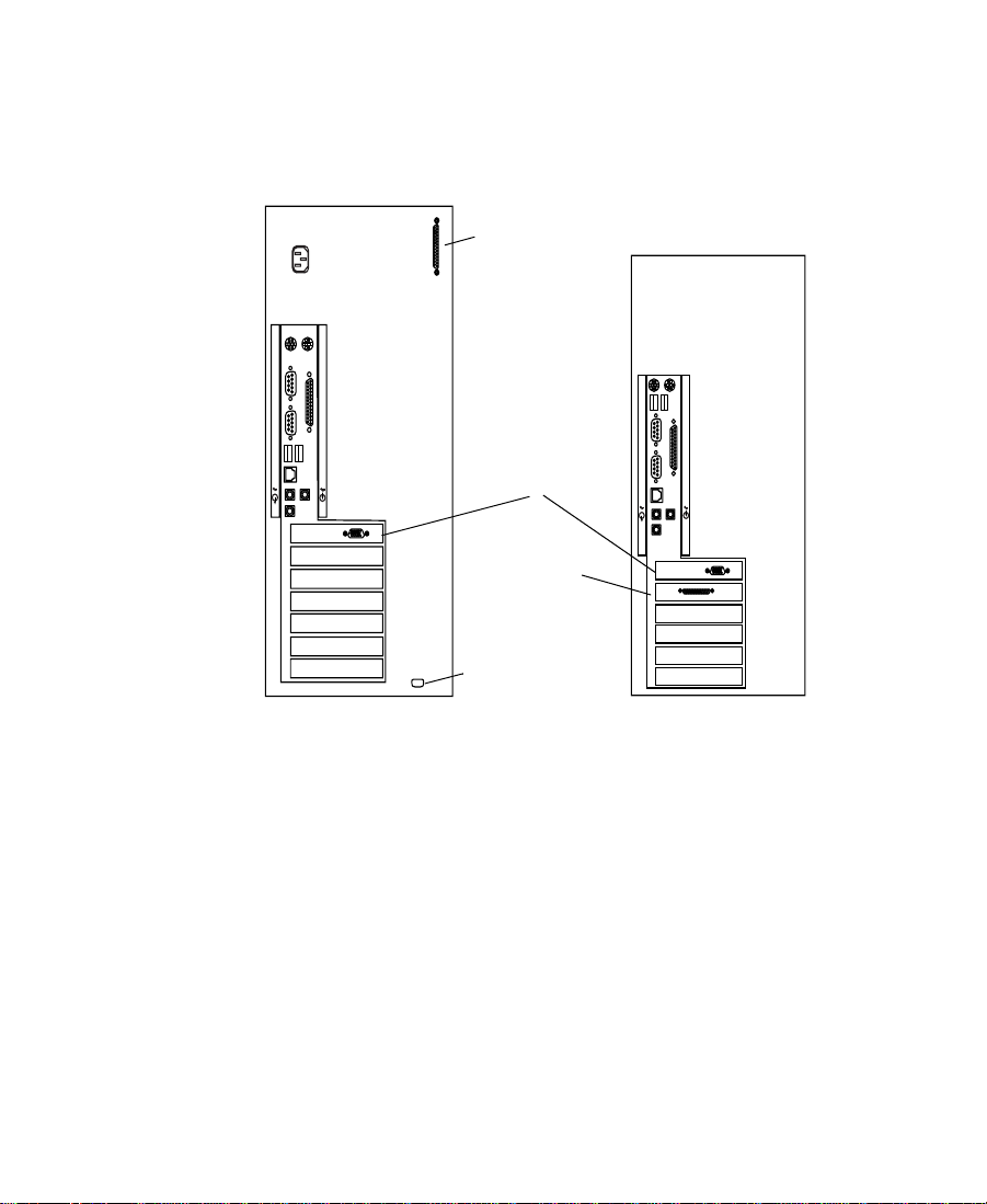
Figure 1-1 Rear View of Systems . . . . . . . . . . . . . . . . . . . . . . . . . . . 23
Figure 1-2 Meridien I/O Box Rear View . . . . . . . . . . . . . . . . . . . . . 27
Figure 1-3 IBM 6866 System Internal Drive Bay Locations. . . . . . 31
Figure 1-4 M Pro System Internal Drive Bay Locations . . . . . . . . 33
Figure 1-5 Avid System Layout . . . . . . . . . . . . . . . . . . . . . . . . . . . . 38
Figure 2-1 Arranging the System . . . . . . . . . . . . . . . . . . . . . . . . . . . 41
Figure 2-2 Meridien I/O Box to System Cable Connection . . . . . 43
Figure 2-3 Digital Media Board Set to Meridien I/O Box
Cable Connection . . . . . . . . . . . . . . . . . . . . . . . . . . . . . . 43
Figure 2-4 Bin Monitor to Display Controller Connection . . . . . . 44
Figure 2-5 21-Inch Bin Monitor Cable Connections. . . . . . . . . . . . 45
Figure 2-6 Edit Monitor to Display Controller Connection . . . . . 46
Figure 2-7 21-Inch Edit Monitor Cable Connections . . . . . . . . . . . 46
Figure 2-8 Attaching Copper Cable to the Controller Board . . . . 48
Figure 2-9 FCDE Connection Locations. . . . . . . . . . . . . . . . . . . . . . 49
Figure 2-10 FCDE Rack-Mount Rail. . . . . . . . . . . . . . . . . . . . . . . . . . 50
Figure 2-11 Locating the FCDE Rails . . . . . . . . . . . . . . . . . . . . . . . . . 51
Figure 2-12 Attaching the FCDE Rails to the Rack
Front Channel . . . . . . . . . . . . . . . . . . . . . . . . . . . . . . . . . . 52
Figure 2-13 Attaching the FCDE Rails to the Rack Middle or
Back Channel . . . . . . . . . . . . . . . . . . . . . . . . . . . . . . . . . . 53
Figure 2-14 Installing an FCDE. . . . . . . . . . . . . . . . . . . . . . . . . . . . . . 54
Figure 2-15 Opening the FCDE Front Door . . . . . . . . . . . . . . . . . . . 55
Figure 2-16 Installing the FCDE Mounting Screws . . . . . . . . . . . . . 55
Figure 2-17 Attaching Copper Cable to the LCC Slot A . . . . . . . . . 56
Figure 2-18 Removing the FCDE Fan Assembly . . . . . . . . . . . . . . . 57
10
Page 11

Figure 2-19 Attaching the FCDE Power Cords. . . . . . . . . . . . . . . . . 58
Figure 2-20 Replacing the FCDE Fan Assembly. . . . . . . . . . . . . . . . 59
Figure 2-21 Inserting a Drive into the FCDE. . . . . . . . . . . . . . . . . . . 60
Figure 2-22 Setting the FCDE ID. . . . . . . . . . . . . . . . . . . . . . . . . . . . . 61
Figure 2-23 SCSI LVD Board Connections . . . . . . . . . . . . . . . . . . . . 63
Figure 2-24 Application Key Connection . . . . . . . . . . . . . . . . . . . . . 64
Figure 2-25 Attaching the Grounding Wrist Strap. . . . . . . . . . . . . . 65
Figure 2-26 Video I/O Board in Meridien I/O Box. . . . . . . . . . . . . 66
Figure 2-27 Removing the SDI Board from Video I/O Board . . . . 67
Figure 2-28 Installing the SDI Board . . . . . . . . . . . . . . . . . . . . . . . . . 68
Figure 2-29 Replacing the Video I/O Board . . . . . . . . . . . . . . . . . . . 68
Figure 3-1 Diagnostic Main Window. . . . . . . . . . . . . . . . . . . . . . . . 74
Figure 3-2 Diagnostic Groups . . . . . . . . . . . . . . . . . . . . . . . . . . . . . . 75
Figure 3-3 Board Information Window . . . . . . . . . . . . . . . . . . . . . . 76
Figure 3-4 Save As Dialog Box . . . . . . . . . . . . . . . . . . . . . . . . . . . . . 76
Figure 3-5 Error Log Window. . . . . . . . . . . . . . . . . . . . . . . . . . . . . . 77
Figure 3-6 Save As Dialog Box . . . . . . . . . . . . . . . . . . . . . . . . . . . . . 77
Figure 3-7 Preference Window — Test Control . . . . . . . . . . . . . . . 78
Figure 3-8 Preference Window — Base Board . . . . . . . . . . . . . . . . 79
Figure 3-9 Preference Window — Video Subsystem. . . . . . . . . . . 80
Figure 3-10 Quick Start Dialog Box . . . . . . . . . . . . . . . . . . . . . . . . . . 81
Figure 3-11 Digital Media Board Set Tests . . . . . . . . . . . . . . . . . . . . 84
Figure 3-12 Cabling for the Pixel Test . . . . . . . . . . . . . . . . . . . . . . . . 90
Figure 3-13 Cabling for the Capture and Playback Test . . . . . . . . . 90
Figure 3-14 Cabling for the Interaction Component Video Test . . 91
Figure 3-15 Cabling for the Interaction Composite Video Test . . . 92
11
Page 12

Figure 3-16 Cabling for the Interaction SDI Video Test . . . . . . . . . 93
Figure 3-17 Cabling for the S-Video Interaction Video Test. . . . . . 94
Figure 3-18 StorEx Main Window . . . . . . . . . . . . . . . . . . . . . . . . . . . 96
Figure 3-19 Toolbar. . . . . . . . . . . . . . . . . . . . . . . . . . . . . . . . . . . . . . . . 98
Figure 3-20 Testing Display. . . . . . . . . . . . . . . . . . . . . . . . . . . . . . . . . 98
Figure 3-21 Preference Window — Tests Tab. . . . . . . . . . . . . . . . . 100
Figure 3-22 Preference Window — Options Tab . . . . . . . . . . . . . . 102
Figure 4-1 Meridien I/O Board Identification . . . . . . . . . . . . . . . 107
Figure 4-2 Eight-Channel Audio Interface Board Connectors . . 108
Figure 4-3 Two-Channel Audio I/O Board Connectors . . . . . . . 109
Figure 4-4 Video I/O Board Connectors . . . . . . . . . . . . . . . . . . . . 111
Figure 4-5 Meridien I/O Box Indicators . . . . . . . . . . . . . . . . . . . . 113
Figure 4-6 Connecting the Client Monitor . . . . . . . . . . . . . . . . . . 115
Figure 4-7 Eight-Channel Synchronization Cabling . . . . . . . . . . 118
Figure 4-8 Black Burst Generator Power Cabling . . . . . . . . . . . . 119
Figure 4-9 Connecting the Black Burst Generator . . . . . . . . . . . . 121
Figure 4-10 Video Deck Control Cabling. . . . . . . . . . . . . . . . . . . . . 122
Figure 4-11 Audio Splitter Rear View . . . . . . . . . . . . . . . . . . . . . . . 124
Figure 4-12 Connecting the Audio Splitter . . . . . . . . . . . . . . . . . . . 125
Figure 4-13 Connecting a Video Deck — Component Signal. . . . 127
Figure 4-14 Connecting Two Video Decks — Component
Signal . . . . . . . . . . . . . . . . . . . . . . . . . . . . . . . . . . . . . . . . 130
Figure 4-15 Connecting a Video Deck — Composite Signal . . . . 132
Figure 4-16 Connecting Two Video Decks — Composite
Signal . . . . . . . . . . . . . . . . . . . . . . . . . . . . . . . . . . . . . . . . 134
Figure 4-17 Connecting a Video Deck — Digital Signal . . . . . . . . 136
Figure 4-18 Connecting Two Video Decks — Digital Signal . . . . 138
12
Page 13

Figure 4-19 Connecting a Video Server . . . . . . . . . . . . . . . . . . . . . . 139
Figure 5-1 MIDI Port Connection . . . . . . . . . . . . . . . . . . . . . . . . . . 141
Figure 5-2 JL Cooper MCS-3000X Fader Controller Rear View . 142
Figure 5-3 Connecting the JL Cooper Fader Controllers. . . . . . . 143
Figure 5-4 Yamaha 01V Mixer Rear View . . . . . . . . . . . . . . . . . . . 144
Figure 5-5 Connecting the JL Cooper Jog/Shuttle Wheel. . . . . . 145
Figure 5-6 Connecting a VTR Emulator. . . . . . . . . . . . . . . . . . . . . 147
Figure 6-1 VLXi Single-Deck Control Cabling . . . . . . . . . . . . . . . 150
Figure 6-2 VLXi Parallel Deck Control Cabling . . . . . . . . . . . . . . 152
Figure 6-3 VLXi Dual-Deck Control Cabling . . . . . . . . . . . . . . . . 154
Figure 6-4 Multiple VLXi Configuration Control Cabling . . . . . 157
Figure B-1 Removing the Side Cover . . . . . . . . . . . . . . . . . . . . . . . 182
Figure B-2 Fan in the System . . . . . . . . . . . . . . . . . . . . . . . . . . . . . . 183
Figure B-3 Fan Tab Location . . . . . . . . . . . . . . . . . . . . . . . . . . . . . . 184
Figure B-4 Extending the Fan . . . . . . . . . . . . . . . . . . . . . . . . . . . . . 185
Figure B-5 Connecting the Fan Power . . . . . . . . . . . . . . . . . . . . . . 185
13
Page 14

Tables
Table 1-1 Peripheral Board Location . . . . . . . . . . . . . . . . . . . . . . . 25
Table 4-1 Eight-Channel Audio Interface Board Identifiers . . . 109
Table 4-2 Two-Channel Audio I/O Board Identifiers . . . . . . . . 110
Table 4-3 Video I/O Board Identifiers . . . . . . . . . . . . . . . . . . . . 111
Table 4-4 Meridien I/O Box Indicator Functions . . . . . . . . . . . 114
14
Page 15

Using This Guide
Congratulations on your purchase of an Avid® Media Composer®,
Film Composer®, or Avid Xpress® system. You can use your system to
create broadcast-quality output incorporating every possible
production element from full-speed, high-resolution footage to
multimedia artwork and animation to titling and computer-generated
effects.
n
Your system might not contain all of the hardware that is described in your
documentation. Our documents describe all hardware regardless of which
model you purchased.
Who Should Use This Guide
This guide is designed for anyone who is installing a system for the
first time, for anyone who might be moving a system, and for anyone
who might be attempting to solve problems that can arise with the
system hardware. This guide is not designed for someone who is
installing board sets in the system.
15
Page 16

About This Guide
The information provided in this guide will help you to understand
the components that are part of a system, connect the components for
proper system functionality, configure and test the system after
installation, and troubleshoot basic problems that can arise during
daily operation.
The Contents that precedes this section lists the topics included in the
guide. They are presented with the following overall structure:
• Chapter 1, “Hardware Overview” helps you to understand the
basic and optional components that make up your system.
• Chapter 2, “Setting Up the System Hardware” helps you to
complete the installation of the components that come with your
system.
• Chapter 3, “Testing the Hardware” provides the basic system
configuration information and the tests that you should perform
before trying to run the Avid software.
• Chapter 4, “Connecting Audio and Video Equipment” explains
synchronization of audio and video equipment and how you
connect audio and video equipment to the system.
• Chapter 5, "Connecting Serial and MIDI Port Devices" explains
how you connect serial and MIDI port devices.
• Chapter 6, “Controlling Multiple Video Decks” provides
information that allows you to connect multiple video decks to
your system using VLXi® systems.
• Chapter 7, “Troubleshooting” provides basic problem-solving
information to help you determine why one or more components
is not functioning as expected.
• Appendix A, “Disk Subsystem Management” provides
explanations of how you partition a disk in a Windows NT®
operating system.
16
Page 17

• Appendix B, “Removing and Installing the Fan” explains how to
remove and install the Avid fan.
• Appendix C, “Regulatory Information” provides regulatory and
safety notices for the system.
•An index at the end of this guide helps you locate the information
you need.
Symbols and Conventions
The Avid hardware documentation uses the following special symbols
and conventions:
1. Numbered lists, when the order of the items is important.
a. Alphabetical lists, when the order of secondary items is
important.
• Bulleted lists, when the order of the items is unimportant.
- Indented dashed lists, when the order of secondary items is
unimportant.
Look here in the margin
for tips.
n
c
w
Courier Bold font identifies text that you type.
In the margin, you will find tips that help you perform tasks more
easily and efficiently.
A note provides important related information, reminders, recommendations,
and strong suggestions.
A caution means that a specific action you take could cause harm to
your computer or cause you to lose data.
A warning describes an action that could cause you physical harm.
Follow the guidelines in this guide or on the unit itself when
handling electrical equipment.
17
Page 18

If You Need Help
If you are having trouble using the system, you should:
1. Retry the action, carefully following the instructions given for that
task in this guide.
2. Check the documentation that came with your hardware for
maintenance or hardware-related issues.
3. Check the Customer Service and News + Publications sections of
the Avid Web site at www.avid.com for the latest FAQs, Tips &
Techniques, Film + Television Update, and other Avid online
offerings.
The Customer Service Knowledge Center provides support
information and documentation for Avid products. To access the
Knowledge Center:
a. Go to www.avid.com.
b. Click Customer Service.
c. Click Knowledge Center.
d. Log in.
n
If you are not already a registered user of the Knowledge Center, register now.
Registered users can access more information.
For the latest versions of the Avid Products Collaboration Guide and
the drive striping tables, click the Documentation tab.
4. For customer support, contact your local Avid Reseller, or contact
Avid Customer Support directly at 800-800-AVID (2843).
18
Page 19

Related Information
The following documents provide more information about the
hardware and software for your system:
• Avid Composer Products Site Preparation Guide (online version)
• Avid iS MediaDrive Setup and User’s Guide
• Avid MediaDrive rS Setup and User’s Guide
• Avid MediaDock LVD Setup and User’s Guide
• The appropriate Avid Composer products release notes
• Avid Products Collaboration Guide
This guide provides step-by-step instructions for transferring
project files, audio files, and graphics and effects files between
various Avid products.
For the most recent version of this guide, see the Documentation
section of the Avid Customer Service Knowledge Center. The
previous section, “If You Need Help”, explains how to access the
Knowledge Center.
If You Have Documentation Comments
Avid Technology continuously seeks to improve its documentation.
We value your comments about this guide, the Help, the Online
Publications CD-ROM, and other Avid-supplied documentation.
Simply e-mail your documentation comments to Avid Technology at
TechPubs@avid.com
Please include the title of the document, its part number, revision, and
the specific section you are commenting on in all correspondence.
19
Page 20

How to Order Documentation
To order additional copies of this documentation from within the
United States, call Avid Telesales at 800-949-AVID (2843). If you are
placing an order from outside the United States, contact your local
Avid representative.
20
Page 21

CHAPTER 1
Hardware Overview
Avid systems allow you to edit video and audio projects digitally, and
to digitize the video and audio in compressed format.
n
Your system might not contain all of the hardware that is described in your
documentation. Our documents describe all hardware regardless of which
model you purchased.
This chapter contains the following sections:
• Avid System Components
• Peripheral Boards
• Audio and Video Equipment
• Storage
• A Typical Avid System Layout
21
Page 22

Avid System Components
Your Avid system is based on two major pieces of equipment that
connect using a twisted-pair cable:
• An Avid supported personal computer (PC) system that executes
the software, contains the digital portion of the Avid Meridien™
III video subsystem (needed to display all graphic features and to
perform edits and 3D effects), and performs disk I/O.
• A Meridien I/O box that contains the analog portion of the Avid
Meridien video subsystem that:
- Digitizes video and audio prior to sending it to the PC in
digital form.
- Changes the digital signal from the PC to analog for output to
the video and audio devices.
- Reformats certain digital signals it receives to and from Avid
format for transfer to and from the PC.
The Platform
All Avid Composer systems and some Avid Xpress systems use an
®
IntelliStation® Z Pro Type 6866 system (IBM 6866 system) that
IBM
contains seven slots, but only six of the slots are available PCI slots (see
Figure 1-1). There is support for MIDI on the IBM 6866 system board.
The Avid Xpress system can also be purchased on an IBM M Pro
system that contains six slots, but only four of the slots are available
PCI slots. There is no support for MIDI on the system board. If you
need MIDI support on an M Pro system, you need to purchase an
optional PCI audio card.
22
Page 23
The minimum amount of memory required for any Avid Composer
system is 384 MB, while the Avid Xpress system requires only 256 MB.
Removing memory is explained in the user’s guide that ships with
each system.
IBM 6866 System
External
SCSI connection
AGP slot
(unused)
SCSI board
as external
connector
MIDI connection
IBM M Pro System
Figure 1-1 Rear View of Systems
The AGP board must be removed from both systems before the Avid
boards are installed. The AGP slot cannot be used by any Avid boards.
One of the main differences between the IBM 6866 system and the
M Pro system is the type of SCSI connections. The IBM 6866 system
has a SCSI connection at the rear of the system that comes from a
dual-channel Ultra3 LVD controller on the system board.
23
Page 24

The M Pro system has no SCSI controller on the system board and uses
a SCSI 2940U2B single-channel LVD PCI board to support the system
drive. The SCSI board also provides an external SCSI connection to the
rear of the system. You can also connect additional internal drives to
this SCSI board.
n
See “Storage” on page 30 for general information concerning storage.
Monitors
Avid systems support the following three monitors:
• The 21-inch Bin monitor displays the Windows NT operating
system desktop.
• The 21-inch Edit monitor displays the Avid software editing
environment.
• The third monitor (Client monitor) displays full-screen video
playback and can be either an NTSC monitor or a PAL monitor.
This monitor is optional.
Avid systems also support monitors of other sizes. You can use most
17-inch multisync monitors in place of the 21-inch monitors, but both
the Bin and Edit monitors must be the same size and model.
Keyboard and Mouse
Although an Avid keyboard and a two-button mouse ship with many
systems, this can change at any time. The Avid keyboard contains
Avid specific keycaps that show defined keys for use with the Avid
software.
24
Page 25

Peripheral Boards
The system uses additional peripheral boards to support video, audio,
compression, effects, and improved data transfer to the hard drives.
The boards are located in the internal PCI slots of the personal
computer or in the Meridien I/O box (an Avid designed standalone
box). Ta bl e 1 -1 lists the board type and location.
Table 1-1 Peripheral Board Location
Board Type Location
Meridien display controller board PCI slot
Meridien III digital media board set PCI slot
Meridien 3D effects board PCI slot
Fibre Channel (F/C) controller board for
standalone F/C (optional)
SCSI UL3D/160 dual-channel LVD board (UL3D)
is optional for all Avid systems
SCSI 2940U2B single-channel LVD board
ships with Avid Xpress on M Pro systems
Meridien video I/O board Meridien I/O box
Meridien eight-channel audio interface board Meridien I/O box
Meridien two-channel audio I/O board Meridien I/O box
Meridien serial digital I/O board (attached to the video I/O board) Meridien I/O box
a. The 2940 is an Ultra2 LVD board used for the internal system drive. It also allows you to
connect LVD drives to an external 68-pin D-type connector. When Ultra3 drives are
attached to this board, they are only capable of Ultra2 speeds.
a
(2940)
25
PCI slot
PCI slot
PCI slot
Page 26

PCI Boards
The following sections explain the functions of each peripheral board
located in an internal PCI slot. Removal of PCI boards is explained in
the user guide that ships with the system.
Meridien Display Controller Board
The system uses the Meridien display controller board (display
controller board) to support the Bin and Edit monitor using one PCI
board. These monitors are supplied with the system.
Meridien III Digital Media Board Set
The Meridien III digital media board set is a PCI board and a daughter
card that provides a PCI interface to the system, deep defocus,
compression and decompression functions, color correction circuitry,
and the use of 24p controlled by the dongle. The board set also
interfaces the 3D board set if present, and acts as an interface to the
Meridien I/O box.
Meridien 3D Effects Board
The 3D effects board provides 3D video effects to enhance video
production. The board uses one PCI slot.
F/C Controller Board
This optional F/C board allows the system to mount the F/C drives,
and access the media and other data stored on the drives in the F/C
enclosure.
SCSI UL3D/160 Dual-Channel LVD Board
The optional SCSI UL3D/160 dual-channel LVD board (UL3D) is used
with all Avid rS MediaDrives and the Avid MediaDock™ LVD storage
system.
26
Page 27

SCSI 2940U2B Single-Channel LVD Board
The SCSI 2940U2B single-channel LVD board (2940) ships with each
IBM M Pro system and is used with all Avid rS MediaDrives and the
Avid MediaDock LVD storage system at Ultra2 speeds.
Since the IBM M Pro system does not have a SCSI controller on the
system board, this board is used for the internal system drive (using
SCSI ID 0) and allows you to connect drives to its external 68-pin
D-type connector.
n
channels. If you need to stripe across two channels, you can purchase the
optional UL3D board and use it in the same system as the 2940.
The Meridien I/O Box
The system uses the peripheral boards in the Meridien I/O box to
support video and audio. The following sections explain the functions
of each peripheral board located in a Meridien I/O box.
Since the 2940 is a single-channel board, you cannot stripe across two
n
Figure 1-2 shows a two-channel audio I/O board. An eight-channel audio
interface board is available that connects to an eight-channel audio I/O device.
AUDIO IN
COMPONENT
COMPOSITE
MIC CHAN 1
IN
ININ
Y
IN
REF
R-Y B-Y
COMPOSITE
S-VIDEO
CHAN 2
Two-channel audio I/O board
CHAN 2
OUT 1 OUT 2 OUT 3IN
DIGITAL VIDEO
SYSTEM
IN / OUT
AES / EBU
IN
OUT
SLAVE CLOCK
OUT
S / PDIF
IN
OUT
LTC
IN
OUT
AUDIO OUT
-10
GAIN 1
GAIN 2
+4
CHAN 1
OUT
B-Y
Y
R-Y
OUT
OUT 1
S-VIDEO
OUT 3
OUT 2
Video I/O board
Serial digital I/O board
Figure 1-2 Meridien I/O Box Rear View
27
Page 28

Meridien Video I/O Board
Each system uses a video I/O board (see Figure 1-2). The video I/O
board has the following features:
• Provides a parallel digital interface between the digital media
board and the analog I/O.
• Digitizes one channel of composite, component (Y, R-Y, B-Y), or
S-Video.
• Converts digital output from the digital media board to an analog
output signal for composite (three outputs), component, and
S-Video.
• Acts as a baseboard for the serial digital I/O (SDI) board.
• Provides a genlock capability to allow the video to be locked to an
external source such as house sync or to a black burst generator
(BBGen).
• Provides an audio slave clock to lock incoming audio to incoming
video.
Meridien Eight-Channel Audio Interface Board
An eight-channel audio interface board that links the system to a
separate eight-channel audio I/O device (Digidesign® 888 I/O™).
The audio I/O device provides connections for up to eight channels of
digital audio or eight channels of analog audio.
Meridien Two-Channel Audio I/O Board
A two-channel audio I/O board (see Figure 1-2) provides connections
for two channels of digital audio, two channels of analog audio, and a
microphone input. This is a standalone board.
Meridien Serial Digital I/O Board
The SDI board (see Figure 1-2) provides physical inputs and outputs
between the video I/O board and a serial digital device.
28
Page 29

Audio and Video Equipment
The system supports add-on hardware for advanced audio and video
input and output capabilities. The system that you purchase
determines whether the hardware is standard with your system or can
be added as an option.
Audio I/O Device
The system supports eight channels of audio by using an
eight-channel audio I/O device. The device allows you to connect up
to eight channels of professional-quality audio equipment, such as
mixers and audio outputs from high-end video decks.
VLXi Multideck Controller
Avid systems support a VLXi multideck controller. It allows you to
connect several video decks to a system and use the software to
control deck operations.
Black Burst Generator
A black burst generator creates a common reference signal that is used
by many of the components external to the system to synchronize
audio and video signals when using multiple video decks.
29
Page 30

Storage
There are two types of storage available in your Avid system:
• Internal storage
• External storage
This section discusses both types of storage and the storage differences
between the IBM 6866 system and the M Pro system.
Supported Internal Storage
Although internal storage options are available in both the IBM 6866
system and the M Pro system, there are major differences between the
number and type of internal options available in these systems. As a
user, you must understand the capabilities and limitations of each
system before you add storage devices.
Figures shown in this section show drive bay locations for both
systems, but you should always refer to the manufacturer’s user guide
that shipped with your computer for more detailed locations and
connections.
n
IBM 6866 Systems
Avid recommends that you have a certified Avid Reseller install any internal
drives in either the IBM 6866 or M Pro systems.
The IBM 6866 system contains internal drives and drive bays
controlled by internal drive controllers.
30
Page 31

Internal Drives and Drive Bays
The IBM 6866 system contains removable-media drives as well as an
internal hard drive.
• Removable drives — a 1.44 MB, 3.5-inch floppy drive (controlled
by an onboard floppy controller) and an IDE CD-ROM
• Internal hard drive — a 9-GB SCSI (the drive size might change at
any time without notice)
There are nine internal drive bays located in the IBM 6866 system.
Access to drive bays 1 to 3 is through the front door. You must remove
the front panel for access to drive bays 4 to 9 (see Figure 1-3).
“Internal Disk Controllers” on page 32 explains what type of device
is recommended for each drive bay.
Drive bay numbers
1
2
456789
Front view with front door
and front panel removed.
3
Floppy drive
CD-ROM
Figure 1-3 IBM 6866 System Internal Drive Bay Locations
31
Page 32

Internal Disk Controllers
The IBM 6866 system has an internal floppy controller (not discussed)
that controls a floppy drive in drive bay 3 (see Figure 1-3). The
remaining two internal disk controllers are:
• An IDE controller with channels 0 and 1. Both channels have the
• A two-channel 7899 Adaptec™ 160 Ultra3 SCSI controller:
capability of having one master device and one slave device
connected, however, only one channel has a cable connected. The
cable has two connectors, one connected to the CD-ROM in drive
bay 2, and an empty connector that you could use to connect an
IDE device in drive bay 1.
Avid uses the power
connector provided for
one of the drive bays to
power a fan needed to
cool the Avid board set.
n
n
c
- Channel A: The cable from channel A connects the boot drive
in drive bay 9, and also connects up to five 1.0-inch hard
drives or four 1.6-inch hard drives in drive bays 4 to 8 (see
Figure 1-3 for drive bay locations).
- Channel B: The cable from channel B connects the internal
controller with the external SCSI connector on the rear of the
system. The cable also provides one SCSI connection for drive
bay 1 shown in Figure 1-3. Channel B can be used for storing
media and connects up to a maximum of 15 SCSI devices,
including the SCSI connector in drive bay 1.
If you need to stripe across two channels to store media, you should not use
any SCSI devices on channel B.
If you have a SCSI device connected to channel B in drive bay 1, and no other
SCSI devices connected externally, you must place an active SCSI terminator
on the external SCSI connector at the rear of the system.
Any SCSI device placed in drive bay 1 and used by SCSI channel B
should be an Ultra3 or Ultra2 device. If you attach a single-ended
fast and wide device to SCSI bus B, the speed of SCSI bus B is
brought to that level. Avid does not recommend the use of a Jaz
type drive on this SCSI adapter.
®
32
Page 33

M Pro Systems
The M Pro system contains internal drives and drive bays controlled
by an internal drive controller and a PCI board.
n
There is no internal SCSI controller on the system board for an M Pro system.
Internal Drives and Drive Bays
The M Pro system contains removable-media drives as well as an
internal hard drive.
• Removable drives — a 1.44 MB, 3.5-inch floppy drive (controlled
by an onboard floppy controller) and an IDE CD-ROM
• Internal hard drive — a 9-GB SCSI (the drive size might change at
any time without notice)
Excluding the two floppy drive bays (drive bays 3 and 4), there are
five internal drive bays located in the M Pro system. Access to all drive
bays is from the left side of the system after you remove the side panel
(see Figure 1-4).
Drive bay numbers
1
2
3
4
5
6
7
CD-ROM
Floppy drive
System drive
Side view with
panel removed.
Figure 1-4 M Pro System Internal Drive Bay Locations
33
Page 34

Internal Disk Controllers
The M Pro system has an internal floppy controller (not discussed)
that controls a floppy drive in drive bay 4 (see Figure 1-4). Drive bay 3
might contain another floppy drive.
The remaining internal disk controller is an IDE controller with
channels 0 and 1. Both channels have the capability of having one
master device and one slave device connected, however, only one
channel has a cable connected. The cable has two connectors, one
connected to the CD-ROM in drive bay 1, and an empty connector that
you could use to connect an IDE device in drive bay 2. Drive bays 1
and 2 are 5.25-inch bays.
All internal SCSI devices are cabled from the 2940 board, and would
be considered part of the 15 total available SCSI devices on the board.
Drive bays 3 to 7 are 3.5-inch bays.
Drive bay 7 contains the system drive, while drive bays 4 and 5 can
connect other SCSI devices using the same cable as the system drive.
Supported External Storage
n
There are three types of external PCI controlled storage options
available for your Avid system:
• Standalone Fibre Channel (F/C)
•SCSI LVD boards
• Avid Unity™ MediaNet
As drive size and drive speed improve, different F/C devices, MediaDrives,
and LVD shuttles will be available for use. Contact your Avid Sales and
Product information line at 800-949-2843 for more product information.
34
Page 35

Standalone Fibre Channel
The standalone F/C system uses an F/C controller board (see “F/C
Controller Board” on page 26) and an F/C disk enclosure that
contains up to 10 drives.
n
SCSI LVD Boards
Avid recommends that you 6-way stripe the disk drives in the F/C disk set
and use them for storing digitized video. Use the remaining four disk drives
or the external SCSI connector for storing digitized audio.
The following 7.2K rpm and 10K rpm F/C storage devices are
supported:
• Shipping F/C devices:
- MEDIArray™ 18 GB 10K rpm
- MEDIArray 73 GB 10K rpm
• Nonshipping F/C devices:
- MSDE 9 GB 7.2K rpm
- MEDIArray 18 GB 10K rpm (early version)
- MEDIArray 50 GB 7.2K rpm
The SCSI LVD boards associated with the systems are:
• The SCSI UL3D/160 dual-channel LVD board (UL3D) can be used
by all Avid systems (see “SCSI UL3D/160 Dual-Channel LVD
Board” on page 26.
• The SCSI 2940U2B single-channel LVD board (2940) is used only
by Avid Xpress software located in M Pro systems (see “SCSI
2940U2B Single-Channel LVD Board” on page 27).
35
Page 36

The following SCSI storage devices are supported:
• Shipping fixed-enclosure devices:
- rS18™/160 MediaDrive LVD
- rS36/160 MediaDrive LVD
- rS73/160 MediaDrive LVD
• Nonshipping fixed-enclosure devices:
- rS9™ LVD, rS18 LVD, and rS36 LVD
- iS9™ Pro and iS18™ Pro (fast/wide)
- rS9 Plus and rS18 Plus (fast/wide)
• Shipping MediaDock LVD devices:
- iS18/160 MediaDrive LVD shuttle
- iS36™/160 MediaDrive LVD shuttle
- iS73/160 MediaDrive LVD shuttle
• Nonshipping MediaDock LVD and MediaDock devices:
- iS9 Plus and iS18 Plus MediaDock LVD shuttles
- iS18 and iS36 MediaDock LVD shuttles
n
- iS9 Plus and iS18 Plus MediaDock Shuttle™ packs (fast/wide)
If you attach any single-ended, fast and wide device to the UL3D board on
Avid systems, the speed changes from Ultra3 to fast and wide speed.
36
Page 37

Avid Unity MediaNet
The Avid Unity MediaNet server and storage subsystem use F/C
storage components to provide the shared storage environment for up
to nine MediaNet clients. MediaNet allows all nine users to
simultaneously read and write to the same shared storage workspace.
The following F/C storage devices are supported:
• Shipping F/C devices:
- MEDIArray 18 GB 10K rpm
- MEDIArray 73 GB 10K rpm
• Nonshipping F/C devices:
- MSDE 9 GB 7.2K rpm
- MEDIArray 18 GB 10K rpm (early style of shipping version)
- MEDIArray 50 GB 7.2K rpm
For more information about Avid Unity MediaNet, see the
documentation that ships with Avid’s Workgroup solutions and
Avid Unity MediaNet.
37
Page 38

A Typical Avid System Layout
As you set up the system, you need to arrange the various components
to avoid exceeding the lengths of the cables that are provided with the
system. You must place the SCSI drives and other components with
short cables close to the PC.
Figure 1-5 shows a sample layout for an Avid system. It contains the
PC, Meridien I/O box, monitors, speakers, several SCSI drives (or an
F/C subsystem or a MediaDock LVD), video decks, an audio I/O
device, and a VLXi multideck controller.
PC
Edit monitorBin monitor
Speaker
VLX
Audio I/O device
i
3
2
1
0
Meridien
I/O box
PULL DOWN
44.1 kHz
AUDIO SYNC
kHz
POWER
48
VIDEO SYNC
O
l
PULL DOWN
44.1 kHz
AUDIO SYNC
kHz
POWER
48
VIDEO SYNC
O
l
ð
rS18 plus
ð
rS18 plus
ð
rS18 plus
ð
rS18 plus
Client monitor
SCSI drives, F/C,
or MediaDock LVD
Figure 1-5 Avid System Layout
38
Video decks
Page 39

CHAPTER 2
Setting Up the System Hardware
After receiving your Avid system, set up the hardware by using the
instructions provided in the following sections:
• Before You Begin
• Assembling the System
• Connecting the Keyboard and Mouse
• Connecting the Meridien I/O Box
• Connecting the Monitors
• Connecting the F/C Disk Subsystem
• Connecting the SCSI Disk Subsystem
• Connecting the Application Key
• Using the Grounding Wrist Strap
• Replacing the SDI Board
• Turning On the System
39
Page 40

Before You Begin
Before you begin installing the system, do the following:
• Unpack all the boxes that came with the hardware kit.
• Check the contents of the hardware kit against the packing list to
confirm that you have received all the parts.
• Position the hardware components.
Checking the Kit Contents
Unpack and check the contents of the kit to ensure you have all the
necessary parts. Depending upon the system you purchase, the kit
might contain the following hardware components:
• A PC with keyboard and mouse
• An application key, commonly referred to as a dongle
• Two monitors
• Two speakers
• Peripheral boards for audio I/O and video I/O (installed in the
Meridien I/O box)
• An eight-channel audio I/O device
• Peripheral boards for editing, effects, and SCSI acceleration
(installed in the PC)
• A disk subsystem - F/C disks for video, with optional Avid
MediaDrives or an Avid MediaDock LVD
• Cables to connect the audio equipment, video equipment,
monitors, keyboard and mouse, and disk subsystem
• A grounding wrist strap
Your system might also include as optional hardware a VLXi to
support multiple video decks.
40
Page 41

Arranging the Components
Start by placing the monitors, keyboard, mouse, and speakers in
positions that are comfortable for viewing and operating the system.
The Meridien I/O box and the audio I/O device must be placed close
to each other. They are connected by cables that are 2 feet (0.61 meters)
in length.
Place the PC and SCSI drives (or an F/C subsystem or a MediaDock
LVD) close together. Position the remaining components, such as
video decks, the VLXi, and additional audio I/O device and video
interface hardware in locations that are easily accessible. Figure 2-1
shows an example arrangement.
ð
rS18 plus
3
ð
rS18 plus
2
ð
rS18 plus
1
ð
rS18 plus
0
O
l
PULL DOWN
44.1 kHz
AUDIO SYNC
kHz
POWER
48
VIDEO SYNC
O
l
PULL DOWN
44.1 kHz
AUDIO SYNC
kHz
POWER
48
VIDEO SYNC
Figure 2-1 Arranging the System
41
Page 42

Assembling the System
All systems shipped directly from Avid, or an Avid certified reseller,
have the peripheral boards already installed in the PC and Meridien
I/O box. Make sure the peripheral boards are installed in the PC and
Meridien I/O box before you continue with the cabling instructions.
c
Before you begin assembling your system, check the release notes
that came with the system to make sure that there are no changes,
additions, or deletions to the following procedures.
Connecting the Keyboard and Mouse
You must connect the keyboard and mouse to the system. The
instructions to connect the keyboard and mouse are specific to the PC
you are using, and are located in the user documentation for your
specific PC.
Connecting the Meridien I/O Box
The Meridien I/O box is a standalone box that contains the audio and
video I/O boards. You connect video equipment to the Meridien I/O
box and audio equipment to the audio I/O device. The Meridien I/O
box is connected to the PC by a 9.8-foot (3-meter) digital data cable.
To connect the Meridien I/O box to the PC:
1. Locate the 9.8-foot (3-meter) digital data cable in the hardware kit.
2. Connect one end of the digital data cable to the Meridien I/O box
at the system interface connector shown in Figure 2-2.
42
Page 43

COMPONENT
COMPOSITE
8 channel
IN
ININ
Y
R-Y B-Y
IN
S-VIDEO
COMPOSITE
REF
OUT 1
B-Y
Y
R-Y
OUT 3
OUT 2
OUT 1 OUT 2 OUT 3IN
OUT
DIGITAL VIDEO
SYSTEM
OUT
IN / OUT
S-VIDEO
SLAVE CLOCK
OUT
Slave Clock
In
IN
LTC
OUT
System interface connector
Figure 2-2 Meridien I/O Box to System Cable Connection
n
Meridien I/O box.
3. Connect the other end of the digital data cable to the connector
labeled M (main) on the digital media board set (see Figure 2-3).
Chapter 4 describes how to connect audio and video equipment to the
&onnection to Meridien I/O box
Connection C not used
Figure 2-3 Digital Media Board Set to Meridien I/O Box Cable
Connection
Connecting the Monitors
The system comes with a high-resolution Bin monitor and a
high-resolution Edit monitor. The Bin monitor displays the
Windows NT operating system desktop, while the Edit monitor
displays the Avid software editing environment.
MC
43
Page 44

The Bin monitor must be located to the left of the Edit monitor. This
allows you to maintain the proper two-screen display needed by the
operating system and the Avid system. Use the following instructions
to connect the monitors to the correct locations on the display
controller board.
n
Avid. Avid provides standard VGA connections for both monitors. If you use
different monitors on your system, see the user’s guide that accompanies the
monitor to complete the monitor installation, or contact the monitor reseller.
Connecting the 21-Inch Bin Monitor
To connect the 21-inch Bin monitor:
1. Locate the monitor VGA cable in the hardware kit.
2. Attach one end of the cable to the VGA connector labeled BOOT
LEFT on the display controller board (see Figure 2-4).
BOOT
The following instructions explain how to connect the monitors provided by
LEFT
EDIT
Display controller board
Monitor VGA cable
Figure 2-4 Bin Monitor to Display Controller Connection
3. Attach the other end of the cable to the VGA input connector on
the Bin monitor (see Figure 2-5).
44
Page 45

VGA connector
AC power connector
SERIAL
SIGNAL-A
R
GBHD
Figure 2-5 21-Inch Bin Monitor Cable Connections
4. Set the termination switch between the COMP HD and VD BNC
connector on the back of the monitor to 75
5. Attach the ac power cord to the ac power connector on the back of
the monitor.
6. Plug the ac power cord into a power strip.
Connecting the 21-Inch Edit Monitor
To connect the 21-inch Edit monitor:
COMP
SYNC
75 Ω
1K Ω
VD
Ω.
1. Locate the monitor VGA cable in the hardware kit.
2. Attach one end of the cable to the VGA connector labeled EDIT on
the display controller board (see Figure 2-6).
45
Page 46

LEFT
BOOT
EDIT
Display controller board
Monitor VGA cable
Figure 2-6 Edit Monitor to Display Controller Connection
3. Attach the other end of the cable to the VGA input connector on
the Edit monitor (see Figure 2-7).
VGA connector
AC power connector
Figure 2-7 21-Inch Edit Monitor Cable Connections
SERIAL
SIGNAL-A
R
GBHD
COMP
SYNC
75 Ω
1K Ω
VD
4. Set the termination switch between the COMP HD and VD BNC
connector on the back of the monitor to 75 Ω.
5. Attach the ac power cord to the ac power connector on the back of
the monitor.
6. Plug the ac power cord into a power strip.
46
Page 47

Connecting the Client Monitor
The Client monitor displays the playback in either NTSC or PAL
format. The Client monitor can be connected to the analog composite
and component output, or to the serial digital (SDI) output of the
Meridien I/O box. SeeChapter 3 for a description of how to connect
the Client monitor to the composite output.
Adjusting the Video Monitors
When the system is started for the first time, you might need to adjust
the monitors that are attached to the display controller board. Controls
to adjust the monitor are part of a tilt-out panel below the monitor
screen. You can change the brightness, contrast, screen size, screen
skew, and other features by using the touchpad on the tilt-out panel.
For information on using these controls, see the user’s guide that is
included with the monitor.
Connecting the F/C Disk Subsystem
Each system ships with a standalone F/C disk subsystem that
connects to an F/C controller board. The F/C controller board allows
the system to mount the F/C drives and access the media files and
other data stored on the drives. The F/C drive enclosure holds up to
ten Fibre Channel drives for a total of 730 GB of storage.
Placing the Components
When you are setting up your Fibre Channel storage subsystem:
• If you are installing a deskside Fibre Channel drive enclosure
(FCDE), locate the FCDE close to the rest of the components in
your system.
47
Page 48

• If you are installing a rack-mount FCDE, make sure that you have
room in the rack to locate the FCDE with your other rack-mount
components.
Connecting to the System
You connect the Fibre Channel storage subsystem directly to the Fibre
Channel controller board in the system. The controller board is
installed before shipment.
Connecting Cables to the Fibre Channel Controller Board
You use a copper cable to connect the FCDE to the controller board. To
connect the cable:
1. Locate a copper cable in the Fibre Channel kit. Look for a cable
with a 9-pin D-type connector on each end.
2. Attach the 9-pin D-type connector on one end of the cable to the
9-pin D-type connector on the board (see Figure 2-8). Secure the
cable with the thumbscrews on the cable connector.
Fibre Channel controller board
9-pin D-type connector
Figure 2-8 Attaching Copper Cable to the Controller Board
Green LED
Copper cable
48
Page 49

Connecting to the Fibre Channel Drive Enclosure
The figures in the following sections refer to the rack-mount FCDE,
which mounts horizontally in a standard NEMA or EIA rack. When
you are installing a deskside model, the FCDE is vertical. Figure 2-9
shows the locations of the components in both the rack-mount FCDE
and the deskside FCDE.
10-slot rack-mount 10-slot deskside
LCC A
Power supplies
behind fan
LCC A
Power
supplies
Figure 2-9 FCDE Connection Locations
You are about to install one of two types of FCDE: a deskside FCDE or
a rack-mount FCDE. You’ll need to select one of the following to
complete your FCDE installation:
• If you are installing a rack-mount FCDE, continue with
“Installing Rack-Mount FCDE Support Rails” on page 50.
• If you are installing a deskside FCDE, continue with “Connecting
Cables to the Fibre Channel FCDE” on page 56.
49
Page 50

Installing Rack-Mount FCDE Support Rails
The rack-mount FCDE can be installed in either a NEMA or an EIA
rack.
To install the FCDE rack-mount rails:
1. Locate a pair of FCDE support rails in the rail kit. The rails fit both
NEMA and EIA racks. Figure 2-10 shows the rails.
Figure 2-10 FCDE Rack-Mount Rail
2. Select the lowest position in the rack where you can mount the
FCDE. The FCDE uses 3.5 U (EIA rack units), or 6 1/8 inches of
rack space. Position the FCDE support rails so that the bottom of
each rail is at the baseline of a U-alignment position (see
Figure 2-11).
50
Page 51

Rack channel hole spacing
1 3/4 in
1 3/4 in
1 3/4 in
EIA rack unit
Figure 2-11 Locating the FCDE Rails
3. Loosen the four nuts on the adjustment screws so that the rail can
Rack front channel
FCDE
Baseline of FCDE is at U-alignment
position between two 1/2-inch holes.
3 U
2 U
1 U
5/8 in
5/8 in
1/2 in
5/8 in
5/8 in
1/2 in
5/8 in
5/8 in
1/2 in
5/8 in
5/8 in
1/2 in
be sized to fit the rack. Do not completely remove the nuts. Leave
them finger tight.
n
4. Place one support rail over the rack front channel and middle or
back channel. The rail ends should be on the outside of the rack
channels.
5. Locate four screws in the rail kit.
If you are installing the rails in a rack that does not have threaded holes, you
will also need to locate four clip nuts in the rail kit. Slip the clip nuts over the
holes in the rack front channels where you will be installing the screws for the
FCDE rails (see Figure 2-12).
51
Page 52

Screws
6. Loosely attach the front of each FCDE support rail to the rack front
channels with the screws (see Figure 2-12).
Attaching Clip Nuts
Rack front channel
Clip nuts
Rack rail
Figure 2-12 Attaching the FCDE Rails to the Rack Front Channel
7. Locate four screws in the rail kit.
n
If you are installing the rails in a rack that does not have threaded holes, you
will also need to locate four clip nuts in the rail kit. Slip the clip nuts over the
holes in the rack middle or back channels where you will be installing the
screws for the FCDE rails (see Figure 2-13).
52
Page 53

8. Loosely attach the rear of each FCDE support rail to the rack
middle or back channel with the screws (see Figure 2-13).
Rack middle
or back channel
Screws
Rack rail
Attaching Clip Nuts
Clip nuts
Figure 2-13 Attaching the FCDE Rails to the Rack Middle or Back
Channel
9. Tighten the screws for each FCDE support rail at the rack front
channel and the rack middle or back channel.
10. Tighten the four adjustment nuts on the support rail.
11. Repeat steps 1 to 10 for the second support rail.
12. If you are installing additional rack-mount FCDEs, repeat
steps 1 to 11 for each pair of FCDE support rails.
53
Page 54
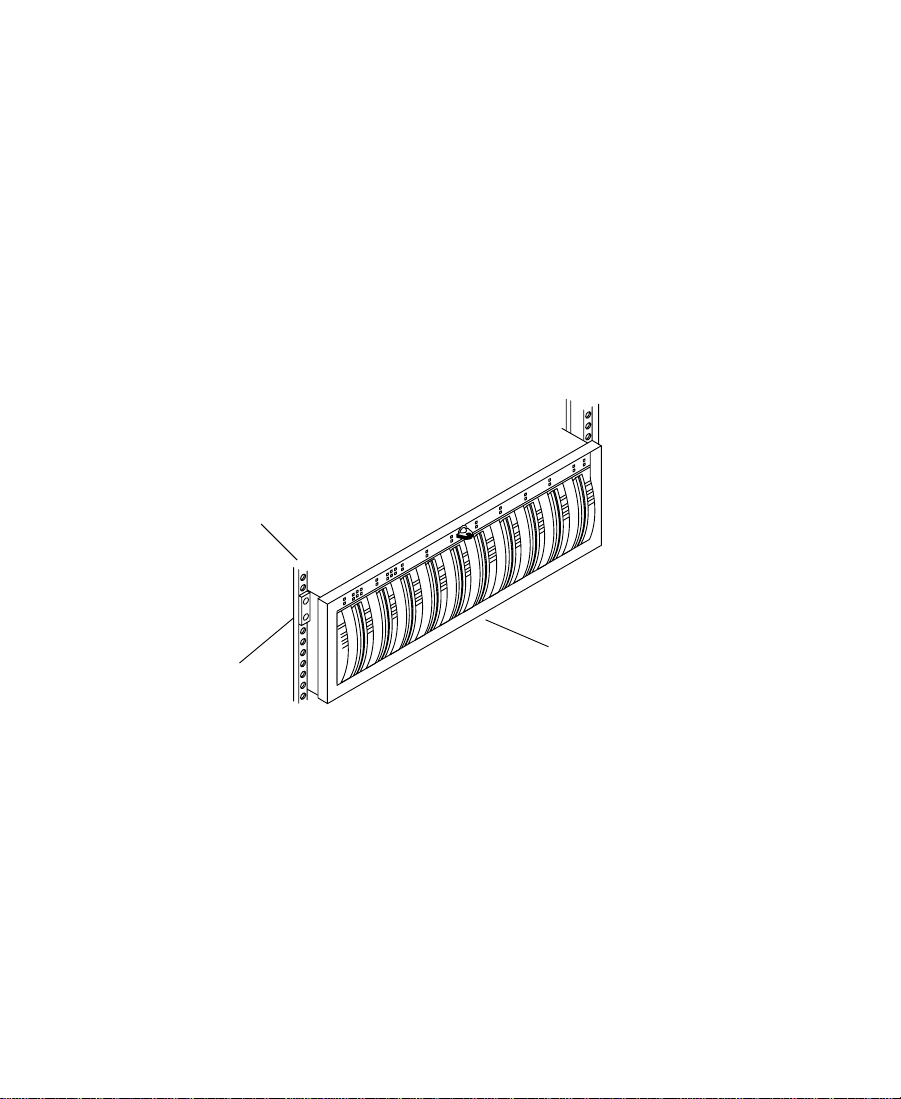
Installing a Rack-Mount FCDE
To install a rack-mount FCDE into a 19-inch rack:
1. Make sure that you have installed the rack-mount FCDE support
rails (see “Installing Rack-Mount FCDE Support Rails” on
page 50). If you are installing several FCDEs, install all the support
rails before you begin to install the FCDEs.
2. From the front of the rack, slide an FCDE into the bottom set of
support rails. Push the FCDE in until the mounting clips on the
side of the FCDE touch the rack front channel. Make sure that the
back corners of the bottom panel slip under the hold-down clips at
the back of the rails (see Figure 2-14).
Rack front channel
Mounting clip
FCDE
Figure 2-14 Installing an FCDE
54
Page 55

3. Open the front door on the FCDE. If the door is locked, locate the
Key
Turn clockwise
to unlock.
Figure 2-15 Opening the FCDE Front Door
4. Locate two mounting screws in the Fibre Channel kit.
5. Attach the FCDE to the rack front channel using one mounting
key in the Fibre Channel kit and unlock the door (see Figure 2-15).
FCDE
Front door
screw on each side of the FCDE (see Figure 2-16).
Mounting clip
Mounting screw
Figure 2-16 Installing the FCDE Mounting Screws
55
Page 56

6. Close the FCDE front door.
7. If you are installing several rack-mount FCDEs, repeat steps 2 to 6
for each additional FCDE.
Connecting Cables to the Fibre Channel FCDE
You connect the FCDE directly to the Fibre Channel controller board.
To connect the Fibre Channel cable to the FCDE:
1. Locate the copper cable that is connected to the Fibre Channel
controller board. It has a 9-pin D-type connector on the end.
2. Attach the 9-pin D-type connector on the cable to the primary
(PRI) 9-pin D-type connector on the link control card (LCC) in slot
A on the back of the FCDE. Figure 2-9 shows the location of LCC
slot A, while Figure 2-17 shows a more detailed view of the
connection. Secure the cable with the thumbscrews on the cable
connector.
LCC
9-pin D-type connector
PRI connector
Copper cable
Figure 2-17 Attaching Copper Cable to the LCC Slot A
56
Page 57

Connecting the Fibre Channel FCDE Power Cords
Each FCDE has two power cord adapters, one for each power supply.
The power cord connectors are located behind the fan assembly. To
connect the power cords to the power supplies in an FCDE:
1. Loosen the fan assembly by pinching the latches together.
2. While you keep the latches pinched, slide the fan assembly out of
the FCDE (see Figure 2-18).
Latches
FCDE
Fan assembly
Slide fan assembly out.
Figure 2-18 Removing the FCDE Fan Assembly
3. Locate two power cord adapters in the Fibre Channel kit.
4. Attach one power cord adapter to the power connector in the
lower right of the bottom power supply (see Figure 2-19). Route
the power cord through the channel below the LCC and out the
back of the FCDE.
57
Page 58

FCDE
Power supply
c
LCC
Channel
Power cord
Figure 2-19 Attaching the FCDE Power Cords
5. Attach the other power cord adapter to the power connector in the
upper left of the top power supply (see Figure 2-19). Route the
power cord down the side of the LCC to the channel below the
LCC and out the back of the FCDE.
Make sure that both power cords do not interfere with the
installation of the fan assembly. The cords must be properly routed
into the channels below the LCCs before the fan assembly is
reinstalled.
Channel
Power supply
n
6. Check to make sure that the FCDE power switches are on.
By default, each FCDE ships with the power switch in the on position. Check
the power switches to make sure they are on.
7. Replace the fan assembly by pinching the latches together and
sliding the assembly into the back of the FCDE (see Figure 2-20).
58
Page 59

Latches
FCDE
Fan assembly
Slide fan assembly in.
Figure 2-20 Replacing the FCDE Fan Assembly
8. Attach the power cords to the open ends of each power cord
adapter.
9. Repeat steps 1 to 8 for each FCDE in your storage subsystem.
10. Plug all the power cords into a power strip or wall outlet.
n
If you are installing a rack-mount FCDE or deskside FCDE with two power
supplies, plug the power cords into two separate power sources to help ensure
that the FCDE will remain running if power to one of the power sources is
interrupted.
Installing Fibre Channel Drives
The Fibre Channel drives might be shipped separately from the FCDE
and will be installed in the FCDE. To install a drive in an FCDE:
1. Open the front door on the FCDE (see Figure 2-15).
2. Locate a drive assembly in the Fibre Channel kit.
59
Page 60

c
Be careful when you are handling the Fibre Channel drives. They
contain open components that can be damaged if the drive is hit or
dropped. Fibre Channel drives are not considered removable drives,
and should only be removed for diagnostic purposes or
replacement.
3. Grasp the drive assembly by the handle.
4. Align the drive assembly with the guides in the FCDE (see
Figure 2-21).
n
For a rack-mount FCDE, the drive assembly is vertical with the latch on top.
For a deskside FCDE, the drive assembly is horizontal with the latch on the
right.
Rack-mount
FCDE
Latch
Drive assembly
Figure 2-21 Inserting a Drive into the FCDE
5. Gently slide the drive into the FCDE until the latch engages to lock
the drive assembly in place. You should hear the latch click when
it engages.
6. Repeat steps 1 to 5 for each drive that you are installing into the
FCDE.
Deskside
FCDE
Drive assembly
Latch
60
Page 61

Setting Fibre Channel Drive Enclosure IDs
Each FCDE in the Fibre Channel storage subsystem needs a unique
enclosure ID to identify the FCDE and determine its drive addresses.
The enclosure IDs must be between 0 and 11. To set an enclosure ID:
1. Locate the enclosure ID switch on the FCDE front panel (see
Figure 2-22).
2. Use the + (plus) button to increment the FCDE ID or the – (minus)
button to decrement the FCDE ID.
3. When you have all the FCDE IDs set, close all the FCDE front
doors.
n
You might need to use a
pen or a paper clip to
push the + and –
buttons to change the
FCDE ID.
For convenience, you might want to set the FCDE IDs in sequential order,
starting with the FCDE that is closest to the system set to ID 0. Setting the
FCDE IDs in sequential order can make it easier to find a particular FCDE
later, and also helps to eliminate duplicate FCDE IDs.
Enclosure ID switch
3
Enclosure ID lights
0
1
0
2
3
Drive
activity
lights
10
8
6
11
9
7
4
1
5
Decrement ID
2
2
Increment ID
2
Figure 2-22 Setting the FCDE ID
61
Page 62

Connecting the SCSI Disk Subsystem
The Avid system supports two types of SCSI LVD boards:
SCSI UL3D/160 Dual-Channel LVD Board
The optional SCSI UL3D/160 dual-channel LVD board (UL3D) is an
Ultra3 controller and can be used with any Avid Composer or
Avid Xpress system. The UL3D supports all Avid rS MediaDrives and
the Avid MediaDock LVD storage system.
n
SCSI 2940U2B Single-Channel LVD Board
n
If you connect fast and wide drives to the UL3D SCSI LVD controller or to
the external SCSI connection of Avid Composer systems, the board or
controller revert to fast, wide mode and you lose the LVD mode throughput.
The SCSI 2940U2B single-channel LVD board (2940) is an Ultra2
controller and ships with each IBM M Pro system using Avid Xpress
software. The 2940 supports all Avid rS MediaDrives and the Avid
MediaDock LVD storage system at Ultra2 speeds.
Since IBM M Pro systems have four available PCI slots and do not
have an internal SCSI controller on the system board, the 2940 is used
for the internal system drive and provides an external 68-pin D-type
connector at the rear of the system.
Since the 2940 is a single-channel board, you cannot stripe across two
channels. If you need to stripe across two channels, you can purchase the
optional UL3D board and use it in the same system as the 2940.
62
Page 63

The following devices are shipping and supported on all UL3D and
2940 SCSI LVD boards and controllers:
• Avid rS LVD MediaDrives (standalone SCSI drives)
• The Avid MediaDock LVD (a standalone SCSI subsystem)
n
For a complete list of supported SCSI devices see “Supported External
Storage” on page 34.
Manuals are provided for Avid rS LVD MediaDrives and the Avid
MediaDock LVD that outline detailed installation instructions.
Overviews of both types are provided in the following sections.
Avid rS LVD MediaDrives
You can purchase one or more Avid rS LVD MediaDrives for storing
the media and other data associated with video and audio projects.
You connect the MediaDrives to the SCSI LVD board. You can identify
the SCSI LVD board in your system by looking at the back of the PC
(see Figure 2-23).
n
UL3D board
The UL3D board uses an ultra high-density connector, while the 2940 board
uses a standard 68-pin D-type connector.
CHANNEL 1 CHANNEL 2
Ultra high-density connector
2940 board
n
68-pin D-type connector
Figure 2-23 SCSI LVD Board Connections
See the Avid MediaDrive rS Setup and User’s Guide for detailed
information on how to connect Avid rS MediaDrives.
63
Page 64

Avid MediaDock LVD
You can also purchase an optional Avid MediaDock LVD storage
system that connects to a SCSI LVD board.
You can purchase an Avid MediaDock LVD for storing the media and
other data associated with video and audio projects. You connect the
MediaDock LVD to the SCSI LVD board. You can identify the SCSI
LVD board in your system by looking at the back of the PC (see
Figure 2-23).
n
See the Avid MediaDock LVD Setup and User’s Guide for detailed
information on how to connect an Avid MediaDock LVD.
Connecting the Application Key
The application key, commonly referred to as a dongle, allows the
Avid software to run on your system. The application key must
connect to the parallel port at the rear of the system. Figure 2-24 shows
how to connect the application key.
Example of system connection
Application key
Figure 2-24 Application Key Connection
64
Page 65

c
Be careful that you do not lose the application key. Your Avid
software does not function without it. If you lose your application
key, you must purchase another key from Avid. Due to the
replacement cost of the application key, Avid recommends that you
insure the application key for the full market cost of your system.
Using the Grounding Wrist Strap
Your Avid system ships with a grounding wrist strap. To prevent any
damage to the PC or any of the peripheral boards, you must wear the
wrist strap when handling the boards.
c
The peripheral boards are sensitive to electrostatic discharge. Do not
handle any of the boards unless you are properly grounded. Put on
the grounding wrist strap and do not take it off until you complete
the board removal and installation.
To use the wrist strap with the Meridien I/O box:
1. Put the grounding wrist strap onto your wrist and adjust the
elastic strap to fit your wrist.
2. Attach the grounding clip to the Meridien I/O box as shown in
Figure 2-25.
Attach wrist
strap here.
Slave Clock
In
8 channel
Figure 2-25 Attaching the Grounding Wrist Strap
65
Page 66

Replacing the SDI Board
The Serial Digital I/O board (SDI) is attached to the video I/O board
and is a field replaceable unit (FRU). To replace the SDI board in the
field:
1. Turn off power to the Meridien I/O box.
2. Remove the video I/O board from the Meridien I/O box.
a. Unscrew (but do not remove) the four thumbscrews that
attach the video I/O board to the Meridien I/O box (see
Figure 2-26).
b. Use the thumbscrews to pull the video I/O board from the
Meridien I/O box.
c. Place the video I/O board on an antistatic surface.
8 channel
Slave Clock
In
Thumbscrews
n
SDI panel
Thumbscrews
Figure 2-26 Video I/O Board in Meridien I/O Box
If you need to replace PCI boards or memory in the system, you must remove
the fan. See Appendix B for instructions on how to remove the fan.
66
Page 67

3. Remove the SDI panel board from the video I/O board (see
Figure 2-27).
a. Remove and save the two blank panel screws.
b. Firmly, but carefully, pull the SDI board from the SDI
connector as shown in Figure 2-27.
c. Pull the SDI connector panel to the rear, through the front
panel of the video I/O board.
Panel screws
Figure 2-27 Removing the SDI Board from Video I/O Board
4. Install the new SDI panel board on the video I/O board.
a. Place the SDI connector panel through the front panel of the
video I/O board (see Figure 2-28).
b. Align the SDI board connector with the connector on the
video I/O board and carefully press the SDI board into the
connector on the video I/O board.
c. Secure the SDI front panel to the video I/O board front panel
using the two panel screws you removed previously.
67
Page 68

SDI front panel
Connector
Panel screws
Figure 2-28 Installing the SDI Board
5. Replace the video I/O board into the Meridien I/O box.
a. Align the edges of the video I/O board in the bottom slot of
the Meridien I/O box (see Figure 2-29).
b. Slide the video I/O board into the Meridien I/O box and
firmly push the board into the connector at the front of the
box.
c. Tighten the four thumbscrews.
Slave Clock
In
8 channel
Thumbscrews
Figure 2-29 Replacing the Video I/O Board
68
Guide rails
Thumbscrews
Page 69

Turning On the System
Once you have the keyboard and mouse, monitors, disk subsystem,
Meridien I/O box, and application key (dongle) installed, you should
turn the system on to make sure it boots properly before you install the
Avid software.
To turn the system on:
1. Make sure all devices are properly plugged into a surge protector
or wall outlet.
2. Make sure the Bin monitor (the monitor attached to the connector
labeled BOOT LEFT on the display controller board) is positioned
to the left of the Edit monitor (the monitor attached to the
connector labeled EDIT on the display controller board).
3. Make sure the Meridien I/O box, disk drives, and monitors are
turned on.
4. Turn on the system as explained in the PC specific user’s guide or
installation guide that ships with your PC.
The system starts to boot. You should see system-specific
information displayed on the Bin monitor.
5. The boot procedure stops and asks you to select the operating
system you want to use. Select Windows NT Workstation 4.0
[VGA Mode].
6. The boot procedure continues and stops again asking you to select
the hardware profile. Select Original Configuration.
The boot procedure continues until the Windows NT logon
message appears on the Bin monitor. The Edit monitor should
remain blank until the blue Windows NT logon screen appears.
69
Page 70

7. Select which account you want to use from the logon window
(administrator or Avid Technology) and press the Enter key. There
is no password set on the system. You must have administrative
privileges to install the Avid software.
If you decide you need a password, see your Windows NT
documentation.
8. Once the system has booted properly without the Avid software
installed, you should install the Avid application and run
diagnostics. See Chapter 3, "Testing the Hardware."
n
The diagnostics use the same drivers as the Avid application, so the Avid
software needs to be installed before you run diagnostics.
70
Page 71

CHAPTER 3
Testing the Hardware
After the Avid system is installed, you need to configure and test the
system to make sure that all of the components and peripheral boards
are functioning properly. Avid supplies a set of diagnostics and a
storage exerciser (Avid StorEx) to help you test the system.
This chapter provides you with enough information to run the
diagnostics and storage exerciser. You should use the Help provided
within the diagnostic for information about the function of specific
buttons and windows.
This chapter contains the following sections:
• Installing the Avid Software
• Diagnostic Overview
• Diagnostic User Interface
• Before You Run Diagnostics
• Running the Diagnostics
• Cabling for the External/User Interaction Test Suite
• Running a Single Test
• Running Avid StorEx
71
Page 72

Installing the A vid Software
After you turn the system on as explained in “Turning On the
System” on page 69, you must install the Avid software. The
diagnostics use the Avid application software drivers. To complete the
software installation, follow the instructions in the release notes that
came with your system. When you complete installing the software,
return to this chapter to run the diagnostics.
Diagnostic Overview
The Avid System Test Pro diagnostics are a set of tests that check the
Meridien III board set located in the PC and the Meridien I/O box.
Run these diagnostics before you begin editing with your system or if
you think your system has a problem. Avid System Test Pro is divided
into two separate test suites:
• Standard Board Diagnostics — Tests the Meridien III board set in the
system with no intervention needed by the user. Always run these
tests first.
• External/User Interaction Board Diagnostics — Tests the I/O portions
of the Meridien III board set and needs user interaction such as
connecting cables and answering questions in a dialog box.
Avid System Test Pro contains Help that provides information on each
button, window, and test for each diagnostic test. To use Help, do one
of the following:
• Select an active window from Avid System Test Pro and press the
F1 key on your keyboard.
• Choose Content from the Help menu.
72
Page 73

Diagnostic User Interface
The user interface for Avid System Test Pro consists of four main
windows and a variety of pop-up dialog boxes. The four windows are:
• Main window
• Board information window
• Error log window
• Preference window
This section briefly explains each major window. More information on
each window can be found by using the Help provided with the
diagnostics.
n
You should read this section completely before you attempt to run the
diagnostics as explained in “Running the Diagnostics” on page 81.
Understanding the Main Window
The Main window (see Figure 3-1) appears automatically the first time
you run the diagnostics. The Main window contains the test selections,
buttons needed to start and stop the diagnostics, and indicators for
test status.
73
Page 74

Toolbar
Test suite
Test tree
Expansion
button
Item name
Item
check box
Item status
System
status bar
Figure 3-1 Diagnostic Main Window
The Main window contains:
• Toolbar — Is a VCR-like user interface that provides control over
the running of the diagnostic. When you first start the diagnostic,
only the start portion of the toolbar is active.
• Test suite — Allows the user to select one of two Tabs: the
Standard test suite or External/User Interaction test suite. Each
test suite has a status indicator that provides status for each test
suite selected.
- The Standard test suite tab — Contains only tests that run
without special cabling or user interaction.
- The External/User Interaction test suite tab — Contains tests
that require user interaction and special cabling. See “Cabling
for the External/User Interaction Test Suite” on page 89 for
information on how to cable the system for these tests.
- Status indicator — Is a round indicator that is yellow if testing,
green if the testing passed, or red if the testing failed. The
same indicator is in the bottom right portion of the Main
window.
74
Page 75
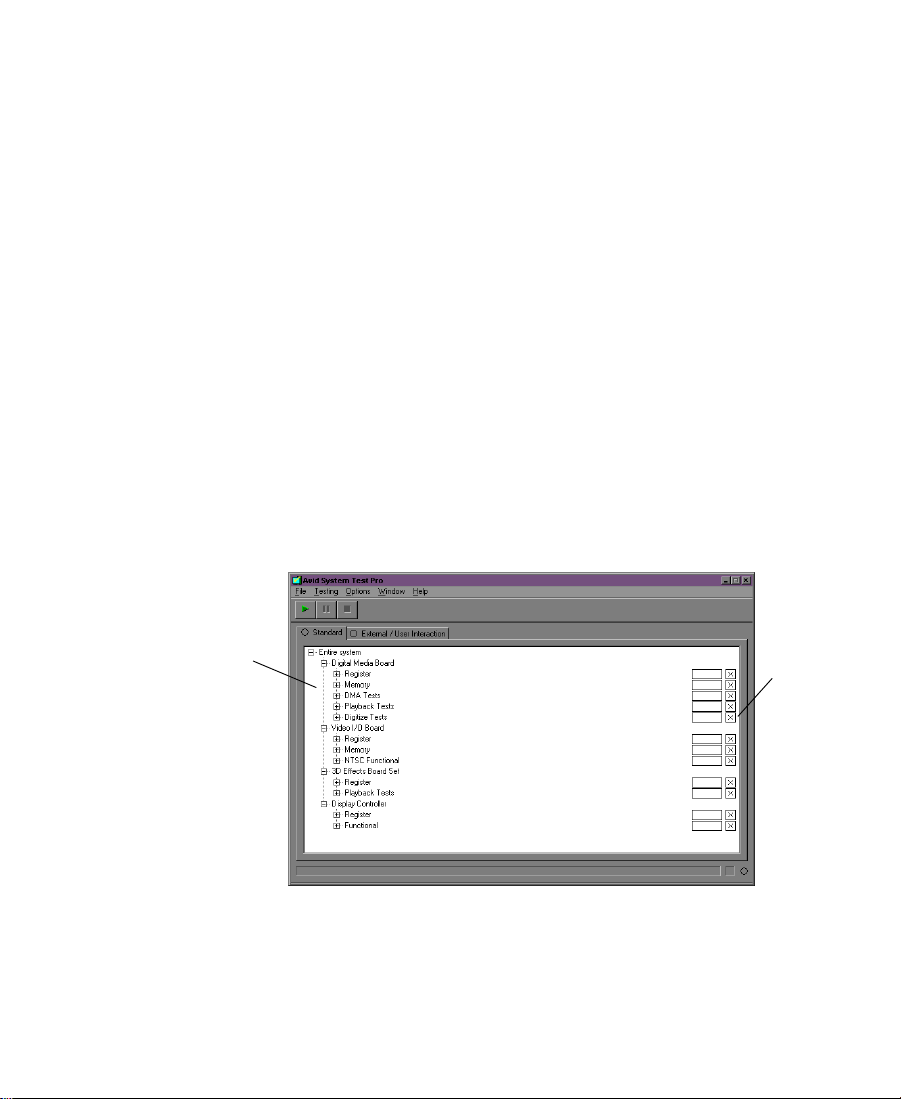
• Te st t r e e — Is a section of the window that contains Expansion
buttons, item names, item check boxes, and item status.
• Expansion button — Clicking on an Expansion button switches
the level of detail for a given item. For example, clicking on the "+"
shows the groups within the item (see Figure 3-2).
• Item name — Is the name of the board being tested or the test
name under that board if the item is expanded.
• Item check box — Selects the item for testing. When the check box
contains an "X," the item is selected for testing. By default, all tests
associated with the Standard test suite are selected when you first
run the diagnostic program from the desktop (see Figure 3-2).
Items are deselected when the check box is clear.
• Item status — Provides status of each test (see the Help for a
complete explanation).
• System status bar — Displays what test is running and provides a
status indicator. It is the same status indicator explained in the Test
suite.
Groups
Figure 3-2 Diagnostic Groups
Selected
items
75
Page 76

Understanding the Board Information Window
The Board Information window provides you with information about
the Avid boards in the system (see Figure 3-3). When you select a
board, information available for the board is displayed.
Board selection
Information
Figure 3-3 Board Information Window
The board information can be saved to a text file by choosing Save
Board Information from the File menu. The board information is saved
to a text file specified in the File name: text box of the Save As dialog
box (see Figure 3-4).
Figure 3-4 Save As Dialog Box
76
Page 77

Understanding the Error Log Window
If a test fails, you should choose Error Log from the Window menu.
The Error Log window opens (see Figure 3-5) and contains
information on all errors that have occurred since the application
started, or since the error log was cleared. Each entry lists the failing
board, the failing test, and the time of the failure. If you double-click a
failure, a more detailed error window opens that can contain
troubleshooting information.
Figure 3-5 Error Log Window
After each failure you can choose Save Error Log from the File menu
and a Save As dialog box appears (see Figure 3-6). If you click the
Include Failure Details check box, the detailed information about the
error is saved to a text file specified in the File name: text box.
Detail check box
Figure 3-6 Save As Dialog Box
77
Page 78

Understanding the Preference Window
The Preference window opens when you choose Preference from the
Options menu. The Preference window controls the way testing
occurs. The window has three tabbed displays to divide the window
into three sections, and control buttons to save or change the choices
for each section. The three tabbed displays are:
Test Control Tab
The Test Control tab allows you to select how the program handles
errors, and the number of times you want the program to run (see
Figure 3-7).
Tabbed pages
Control buttons
Figure 3-7 Preference Window — Test Control
You can choose to continue, pause, or stop on an error by clicking the
radio button in the Error handling region of the window. You can also
choose to loop the test continuously or type in the number of times
you want the test to run by clicking the radio button in the Looping
region of the window.
The default is "Stop on error" and to loop once.
78
Page 79

Base Board Tab
The Base Board tab determines how some of the processor board data
is routed. The data can be routed through the display controller or
through the external Meridien I/O box to the selected output. By
default, both of these options are deselected (see Figure 3-8).
Figure 3-8 Preference Window — Base Board
79
Page 80

Video Subsystem Tab
The Video Subsystem tab, see Figure 3-9, allows you to override the
default video standard of the Meridien I/O box to NTSC, NTSC-EIAJ,
or PAL. The Meridien I/O box is normally defaulted to NTSC in the
United States. If the default is set to NTSC and you want to test the
PAL functions, you must change the video standard to PAL and restart
the diagnostic (the Preferences are only looked at during application
startup).
Control Buttons
Figure 3-9 Preference Window — Video Subsystem
The control buttons allow you to OK your selection, cancel your
selection, return all selections in the Preference window to the default
state by clicking the Default button, or receive Help.
80
Page 81

Quick Start Dialog Box
The Quick Start dialog box appears when you start the diagnostic
program (see Figure 3-10). This dialog box, labeled Avid System Test
Pro Quick Start, describes what you need to do to start testing the
standard set of diagnostics using all test program defaults. The
defaults, as sent from the factory, include the use of NTSC video.
Figure 3-10 Quick Start Dialog Box
Before You Run Diagnostics
Prior to running Avid System Test Pro you should:
• Install the system components as explained in Chapter 2.
• Since the diagnostics use the same drivers as the Avid application,
you must install the Avid software as explained in the release
notes.
Running the Diagnostics
You should run both test suites of Avid System Test Pro diagnostics to
assure that the Avid board sets are functioning properly. You should
run the Standard test suite first, and if the Standard test suite passes,
run the External/User Interaction test suite.
81
Page 82

Running the Standard Test Suite
Once you have installed the diagnostics and selected the proper mode,
you should run the Standard test suite. To run the Standard test suite:
1. Click Start, point to Programs, point to Avid, point to Utilities, and
select Avid System Test Pro.
Avid System Test Pro starts, the Main window opens, and the
Quick Start dialog box appears explaining what you need to do to
run the Standard diagnostics using default settings.
2. Click OK in the Quick Start dialog box.
3. Click the Start button from the toolbar in the Main window.
Since the Standard tests are all selected by default, they run with
the status shown in the Item status boxes in the Main window.
4. Do one of the following:
- If the tests pass, continue testing at “Running the
External/User Interaction Test Suite” on page 83.
- If any test fails, a dialog box appears telling you to open the
Error Log window.
If this is the first time the tests have failed, see Chapter 7,
"Troubleshooting," for possible solutions to the problem.
If you have tried the solutions in Chapter 7 and the
diagnostics still fail, contact your support provider or Avid
Customer Support at 800-800-AVID (2843).
82
Page 83

Running the External/User Interaction Test Suite
There are three different items tested by the External/User Interaction
test suite:
• Digital media board set— Has two interaction tests that require
specific cabling.
• Video I/O board — Has four external tests that require you to
cable selected inputs to selected outputs before you run the tests.
• Audio I/O board — Has one external test that requires special
cabling for eight-channel systems.
All of the External/User Interaction tests displayed under these items
are deselected by default, and you must select each test to run them.
n
Some of these tests can be selected together and run simultaneously.
Testing the Digital Media Board Set
There are two External/User Interaction tests for the digital media
board set, the Pixel DMA Loopback via/DVIO (pixel test) and the
Capture Playback Utility (capture and playback test).
The pixel test sends data out of the digital media board set and back
into the digital media board set. Always run this External/User
Interaction test before you run any of the other tests.
The capture and playback test captures and digitizes incoming data
and plays it back to allow you to see if it was digitized properly.
83
Page 84

Running the Pixel Test
To run the pixel test:
1. Click Start, point to Programs, point to Avid, point to Utilities, and
2. Click OK in the Quick Start dialog box.
3. Select the External/User Interaction tab from the Main window.
4. Click the Expansion button next to the item, Digital Media Board
5. Click the Expansion buttons next to DMA Tests and Digitize Tests
6. Select the pixel test by clicking the check box to the right of the test
select Avid System Test Pro.
Avid System Test Pro starts, the Main window opens, and the
Quick Start dialog box appears explaining what you need to do to
run the Standard diagnostics using default settings.
set. Two groups open, DMA Tests and Digitize Tests (see
Figure 3-11).
to display the tests:
- Pixel DMA Loopback via/DVIO (pixel test)
- Capture Playback Utility (capture and playback test)
(make sure all other tests are deselected).
Expansion
button
Tests
Check
boxes
Figure 3-11 Digital Media Board Set Tests
84
Page 85

7. Cable the digital media board set for the pixel test as explained in
“Cabling for the Digital Media Board Set” on page 89.
8. Click the Start button from the toolbar in the Main window.
The pixel test runs with the status shown in the Item status boxes
in the Main window.
9. Do one of the following:
- If the test passes, consider this part of the system in working
order.
- If the test fails, a dialog box appears telling you to open the
Error Log window.
If this is the first time the tests have failed, see Chapter 7,
"Troubleshooting," for possible solutions to the problem.
If you have tried the solutions in Chapter 7 and the
diagnostics still fail, contact your support provider or Avid
Customer Support at 800-800-AVID (2843).
Running the Capture and Playback Test
To run the capture and playback test:
1. Click Start, point to Programs, point to Avid, point to Utilities, and
select Avid System Test Pro.
Avid System Test Pro starts, the Main window opens, and the
Quick Start dialog box appears explaining what you need to do to
run the Standard diagnostics using default settings.
2. Click OK in the Quick Start dialog box.
3. Select the External/User Interaction tab from the Main window.
4. Click the Expansion button next to the item, Digital Media Board
set. Two groups open, DMA Tests and Digitize Tests (see
Figure 3-11).
85
Page 86

5. Click the Expansion buttons next to DMA Tests and Digitize Tests
to display the tests:
- Pixel DMA Loopback via/DVIO (pixel test)
- Capture Playback Utility (capture and playback test)
6. Select the capture and playback test by clicking the check box to
the right of the test (make sure all other tests are deselected).
7. Cable the digital media board set for the capture and playback test
as explained in “Cabling for the Digital Media Board Set” on
page 89.
8. Click the Start button from the toolbar in the Main window.
The capture and playback test runs displaying a dialog box asking
if you want to capture or play back.
9. Start the video deck and click Capture.
10. Click Playback when the dialog box reappears.
The video you captured is played back.
11. Do one of the following:
- If the test passes, consider this part of the system in working
order.
- If the test fails, a dialog box appears telling you to open the
Testing the Video I/O Board
You can run each video I/O board test separately, but the following
procedure allows you to run as many tests at one time as you can for
efficiency.
Error Log window.
If this is the first time the tests have failed, see Chapter 7,
"Troubleshooting," for possible solutions to the problem.
If you have tried the solutions in Chapter 7 and the
diagnostics still fail, contact your support provider or Avid
Customer Support at 800-800-AVID (2843).
86
Page 87

To run all of the External/User Interaction video I/O tests:
1. Click Start, point to Programs, point to Avid, point to Utilities, and
select Avid System Test Pro.
Avid System Test Pro starts, the Main window opens, and the
Quick Start dialog box appears explaining what you need to do to
run the Standard diagnostics using default settings.
2. Click OK in the Quick Start dialog box.
3. Select the External/User Interaction tab from the Main window.
4. Select the Video I/O Board from the Main window (this selects all
of the tests).
5. Cable all of the devices to test as explained in “Cabling for the
Video I/O Board” on page 91.
6. Use the Expansion button to display the groups under the item,
Video I/O Board.
7. Click the Start button from the toolbar in the Main window.
The External/User Interaction diagnostics run with the status
shown in the Item status boxes in the Main window.
8. Do one of the following:
- If the test passes, consider this part of the system in working
order.
- If the test fails, a dialog box appears telling you to open the
Error Log window.
If this is the first time the tests have failed, see Chapter 7,
"Troubleshooting," for possible solutions to the problem.
If you have tried the solutions in Chapter 7 and the
diagnostics still fail, contact your support provider or Avid
Customer Support at 800-800-AVID (2843).
87
Page 88

Testing the Audio I/O Board
There is one External/User Interaction test for the audio board, the
tone test.
The tone test sends a tone out of the audio board to the speakers. If
you hear the tone the test passes. If your speakers seem to work in
your Avid application there is no need to run this test.
Running the Tone Test
Before you run the tone test make sure the speakers are cabled as
explained in “Connecting the Audio Splitter” on page 124 and power
is applied to the speakers.
To run the tone test:
1. Click Start, point to Programs, point to Avid, point to Utilities, and
select Avid System Test Pro.
Avid System Test Pro starts, the Main window opens, and the
Quick Start dialog box appears explaining what you need to do to
run the Standard diagnostics using default settings.
2. Click OK in the Quick Start dialog box.
3. Select the External/User Interaction tab from the Main window.
4. Select the Audio Board from the Main window (this selects the
tone test).
5. Click the Start button from the toolbar in the Main window.
The External/User Interaction diagnostics run with the status
shown in the Item status boxes in the Main window.
6. A dialog box appears asking if the tone was heard.
- If the tone was heard, consider this part of the system in
working order.
- If the tone was not heard, make sure the cables are properly
connected and the volume is turned up on the speakers.
88
Page 89

If the cables are properly connected and all other diagnostics
pass except the tone test, contact your support provider or
Avid Customer Support at 800-800-AVID (2843).
Cabling for the External/User Interaction Test Suite
The digital media board set and video I/O board need different
cabling when you run the External/User Interaction diagnostics. The
cabling for each of these boards is explained in the following sections.
Cabling for the Digital Media Board Set
The digital media board set has two External/User Interaction tests.
You must cable and run each test separately.
Cabling for the Pixel Test
To cable for the pixel test on the digital media board set:
n
These instructions assume that the system cable is connected between the
digital media board set and the video I/O board as explained in “Connecting
the Meridien I/O Box” on page 42.
1. Disconnect the system cable from the video I/O board in the
Meridien I/O box.
2. Connect the end of the cable you just disconnected to the C
connector of the digital media board set (see Figure 3-12). Return
the cable to its original position after the test.
89
Page 90

MC
Figure 3-12 Cabling for the Pixel Test
Cabling for the Capture and Playback Test
The capture and playback test checks the path you need for digitizing
and playback. To cable for the capture and playback test on the
digital media board set:
1. Make sure you have the system cable between the digital media
board set and the Meridien I/O box connected.
2. Connect the BNC connector of a cable to COMPOSITE IN of the
video I/O board. Connect the other end of the cable to the
COMPOSITE OUT of a video deck (see Figure 3-13).
3. Connect the BNC connector of a cable to COMPOSITE OUT1 of
the video I/O board. Connect the other end of the cable to a
monitor that is capable of inputting a composite signal.
Slave Clock
8 channel
In
LTC
SLAVE CLOCK
SYSTEM
IN / OUT
IN
OUT
OUT
COMPONENT
COMPOSITE
From COMPOSITE OUT
on video deck
IN
ININ
Y
R-Y B-Y
Y
IN
COMPOSITE
REF
R-Y
S-VIDEO
OUT 1
OUT 2
OUT 1 OUT 2 OUT 3IN
OUT
B-Y
DIGITAL VIDEO
OUT
S-VIDEO
OUT 3
To COMPOSITE IN
on a monitor
Figure 3-13 Cabling for the Capture and Playback Test
90
Page 91

Cabling for the Video I/O Board
All of the External/User Interaction tests for the video I/O board can
be run at the same time. To cable the video I/O board in the Meridien
I/O box to run the External/User Interaction tests:
1. Locate the following cables in the hardware kit:
- One cable labeled "2 analog/4 digital" — Two male XLR
connectors on one end, and two female XLR connectors at the
other end
- One cable labeled "Component Video" — Three BNC
connectors at both ends
- Two cables labeled "Serial Digital" — A BNC connector at both
ends
2. Connect the cable labeled "Component Video" to the video I/O
board as shown in Figure 3-14.
- Connect one end of the cable (using the three BNC connectors)
to COMPONENT OUT on the video I/O board as follows:
The BNC attached to the green wire to the connector labeled Y.
The BNC attached to the red wire to the connector labeled
R-Y.
The BNC attached to the blue wire to the connector labeled
B-Y.
Slave Clock
8 channel
COMPONENT
COMPOSITE
IN
ININ
Y
R-Y B-Y
Y
IN
COMPOSITE
REF
R-Y
S-VIDEO
OUT 1
OUT 2
OUT 1 OUT 2 OUT 3IN
OUT
B-Y
OUT
S-VIDEO
OUT 3
DIGITAL VIDEO
SYSTEM
IN / OUT
SLAVE CLOCK
In
LTC
IN
OUT
OUT
Figure 3-14 Cabling for the Interaction Component Video Test
91
Page 92

- Connect the other end of the cable (using the three BNC
connectors) to COMPONENT IN on the video I/O board as
follows:
The BNC attached to the green wire to the connector labeled Y.
The BNC attached to the red wire to the connector labeled R-Y.
The BNC attached to the blue wire to the connector labeled
B-Y.
3. Connect the first cable labeled "Serial Digital" to the video I/O
board as shown in Figure 3-15.
n
n
The Serial Digital cable is a high-quality cable shipped for use with the SDI
video, and can be used for composite video since they both use the 75-Ω BNC
connectors.
- Connect one end of the cable to COMPOSITE IN on the video
I/O board.
- Connect the other end of the cable to COMPOSITE OUT1 on
the video I/O board.
To test OUT2 and OUT3 outputs, you can run the test two more times
connecting this end of the cable to OUT2 and then to OUT3.
Slave Clock
8 channel
In
LTC
SLAVE CLOCK
SYSTEM
IN / OUT
IN
OUT
OUT
COMPONENT
COMPOSITE
IN
ININ
Y
R-Y B-Y
Y
IN
COMPOSITE
REF
R-Y
S-VIDEO
OUT 1
OUT 2
OUT 1 OUT 2 OUT 3IN
OUT
B-Y
DIGITAL VIDEO
OUT
S-VIDEO
OUT 3
Figure 3-15 Cabling for the Interaction Composite Video Test
92
Page 93

4. Connect the second cable labeled "Serial Digital" to the video I/O
board as shown in Figure 3-16.
n
n
The Serial Digital cable is shipped for use with the SDI video and composite
video since they both use the 75-Ω BNC connectors.
- Connect one end of the cable to IN on the Serial Digital
portion of the video I/O board.
- Connect the other end of the cable to OUT2 on the Serial
Digital portion of the video I/O board.
Slave Clock
8 channel
In
LTC
SLAVE CLOCK
SYSTEM
IN / OUT
IN
OUT
OUT
COMPONENT
COMPOSITE
IN
ININ
Y
R-Y B-Y
Y
IN
COMPOSITE
REF
R-Y
S-VIDEO
OUT 1
OUT 2
OUT 1 OUT 2 OUT 3IN
OUT
B-Y
DIGITAL VIDEO
OUT
S-VIDEO
OUT 3
Figure 3-16 Cabling for the Interaction SDI Video Test
To test OUT1 and OUT3 outputs, you can run the test two more times
connecting this end of the cable to OUT1 and then to OUT3.
93
Page 94

Avid ships an S-Video cable with the system. If you need to run the
interaction S-Video test, connect the cable as shown in Figure 3-17 and
use Help to select the S-Video test and run it separately.
• Connect one end of the S-Video cable to S-VIDEO IN on the video
I/O board.
• Connect the other end of the S-Video cable to S-VIDEO OUT on
the video I/O board.
COMPONENT
COMPOSITE
Figure 3-17 Cabling for the S-Video Interaction Video Test
Running a Single Test
Slave Clock
8 channel
IN
ININ
Y
R-Y B-Y
Y
IN
COMPOSITE
REF
R-Y
S-VIDEO
OUT 1
OUT 2
OUT 1 OUT 2 OUT 3IN
OUT
B-Y
DIGITAL VIDEO
OUT
S-VIDEO
OUT 3
In
LTC
SLAVE CLOCK
SYSTEM
IN / OUT
IN
OUT
OUT
If a test fails and you think you have fixed the problem, or if you want
to run one test by itself, you need to know how to run a single test. To
run a single test:
1. Navigate to the test you want to run by using the Expansion
buttons explained in “Understanding the Main Window” on
page 73.
2. Select the test you want to run using the pointer.
3. Right-click the mouse button, and choose Test from the pop-up
menu (the test is automatically enabled if run as a single test).
94
Page 95

Running Avid StorEx
Avid StorEx is a general-purpose, hard-drive exerciser program. It
verifies the operation of SCSI hard drives connected to a SCSI
accelerator board or a Fibre Channel (F/C), PCI-based Avid system.
The program also provides test status information that is helpful for
troubleshooting a drive problem. Avid Customer Support might
instruct you to use StorEx as part of the process of troubleshooting a
problem with a hard drive.
StorEx requires a working Avid system in order to function correctly.
The program assumes that the system processor and memory are
functioning normally. The F/C controller and the SCSI accelerator
board must be functioning and be able to accept commands and return
results.
StorEx is installed by the same installation procedure that installs Avid
application software.
The Main Window
The Main window provides a graphical user interface that guides you
through StorEx. The Main window provides important information,
making sure that you are aware of the devices available for testing and
the results of each test (see Figure 3-18).
95
Page 96
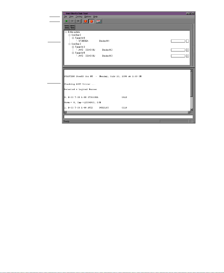
Menu
Toolbar
Testing
display
Console
display
Figure 3-18 StorEx Main Window
The Main window is divided into four areas:
•Menu
• Toolbar
• Testing display
• Console display
96
Page 97

The Menu
The StorEx Main menu is at the top of the display and provides the
following functions:
• File — Allows you to quit the program by choosing Exit from the
File menu.
• View — Allows you to define what you want to see in the Console
display. The available choices are:
- Toolbar
- Testing display (also select by pressing and holding Alt+1)
- Console display (also select by pressing and holding Alt+2)
• Te s t in g — Allows you to control the testing. You can choose to:
- Set all tests to the default state.
- Start the testing.
- Pause the testing (not yet implemented).
- Stop the testing.
• Options — Allows you to open the Preference window (see “The
Preference Window” on page 99) and to define what type of error
causes the test to stop:
The Toolbar
- Stop on hard error
- Stop on any error
• Help — Lists the StorEx revision level.
The toolbar is a VCR-like user interface that provides control over the
running of the diagnostic. When you first start the diagnostic, only the
start portion of the toolbar is active. Each toolbar button is explained
in Figure 3-19.
97
Page 98

Start Pause
The Testing Display
Stop
Stop on
any error
Stop on
hard error
Display
summary
Figure 3-19 Toolbar
The Testing display (see Figure 3-20) appears by default in the Main
window when you start StorEx. The Testing display shows the SCSI
buses and attached disks found by StorEx during the scan of the SCSI
buses, the device status boxes, and the check boxes. To open the
Testing display, choose Testing from the View menu or press and hold
Alt+1. To close the Testing display, choose Testing from the View menu
or press and hold Alt+1. The Testing display allows you to:
• Show the system devices attached to the adapters found by StorEx
when it starts.
• See the status of the devices on the system in the status box.
• Select the devices you want to test by clicking the check box.
SCSI bus
Target ID
Device number
Status box Check box
Figure 3-20 Testing Display
98
Page 99

The target ID is actually the physical disk address of the disk on the
SCSI bus set by switches at the rear of the disk drive.
The device number is a number assigned by StorEx that helps to
identify the disks in the display console printout. The device numbers
have nothing to do with the SCSI bus the disk is attached to.
n
The Testing display is shown in Figure 3-20 with the status box and check
box on the right side of the display. The Testing display is really a window
within the Main window, and can be sized independently. If you make the
Main window smaller without resizing the Testing display, you can cut the
status box and check box from view. If you want to make the Main window
smaller, you should resize the Testing display to the smaller size first, and
then resize the Main window.
The Console Display
The Console display shows a record of the output from StorEx. To
open the Console display, choose Console from the View menu or
press and hold Alt+2. To close the Console display, choose Console
from the View menu or press and hold Alt+2.
The Preference Window
The Preference window appears when you choose Preference from the
Options menu (see Figure 3-21). The Preference window controls the
way testing occurs. The window has two tabs that divide the window
into two sections, and control buttons to save or change the choices for
each section. The two tabbed displays are:
•Tests
• Options
99
Page 100

The Tests Tab
When you click the Tests tab a display appears that allows you to
select the tests that you want to run on the selected hard drives.
The tests are divided into two types: non-destructive tests and
destructive tests.
• Non-destructive tests only read the data that is on the hard drive.
They do not write any data to the hard drive.
• Destructive tests write data to the hard drive and then read that
data. The data is then compared to the original data to verify that
the write and read functions of the hard drive are working
correctly. These tests destroy any data and file system structure
that is on the hard drive.
Figure 3-21 Preference Window — Tests T ab
100
 Loading...