

Page 1

MediaCentral® Platform Services
Installation and Configuration Guide Version 2.4
Important Information
This document provides instructions to install and configure Avid MediaCentral Platform
Services (MCS) v2.4. For a complete list of qualified products, see the Avid MediaCentral
Platform Services ReadMe.
For the latest information on the MediaCentral Platform Services, see the documentation
available from the MediaCentral Platform Services
are occasionally issued after initial release.
For information on upgrading to MCS 2.4 from an earlier release, see the Avid MediaCentral
Platform Services Upgrading Guide, available on the MediaCentral Platform Services
Avid Knowledge Base.
For information on configuring Media | Index, see the Avid Media | Index Configuration Guide,
which is currently available internally only.
page of the Avid Knowledge Base. Updates
page of the
For information on installing Media | Distribute, see the Media |Distribute Installation and
Configuration Guide available on the MediaCentral Platform Services
Knowledge Base.
Note: Throughout this document, “Avid MediaCentral Platform Services” will be referred to as
“MCS”. “Red Hat Enterprise Linux” will be referred to as “RHEL”.
Note: The RHEL deployment used in an MCS environment is a command-line based operating
system. The installation process will require the editing of various system files. Although
multiple text editors exist, the tool used throughout this document is “vi”. If needed, a short
introduction to vi is included in the
Note: When working in Linux, this guide assumes the user is logged in as the “root” user.
Perform all commands and server configuration as the “root” user.
MediaCentral Platform Services Concepts and Clustering Guide.
page of the Avid
Page 2

MCS 2.4 Installation and Configuration Guide
Revision History
Date Revised
Changes Made
• Added restart of “avid-acs-ctrl-core” to Multi-Zone
•
MediaCentral 2.4.0 First Publication
November 20, 2015
October 29, 2015
September 24, 2015
configuration process.
• Minor update to Configuring Unicast Cluster
Communication.
Simplified Setting Gluster Volume Ownership process
• Expanded options for Modifying application.properties
• Other minor updates
• GlusterFS is now included with MCS. Updates made to
the installation and configuration process
• Added information regarding Desktop Notifications
feature
• Updated guidelines for MCDS installation location
• Updated installation instructions for Multi-Zone
configurations
• Updated installation instructions for the Closed
Captioning Service
• Updated Verifying the hosts File Contents
. Virtual
Cluster name and IP now required in the local hosts file
• Appendix E: Avid MediaCentral | UX Desktop
2
Page 3

MCS 2.4 Installation and Configuration Guide
Contents
Important Information ....................................................................................................................... 1
Revision History .................................................................................................................................. 2
ART I: INSTALLATION PREREQUISITES .......................................................................................................... 11
P
Chapter Overview .................................................................................................................................... 12
Before You Begin ...................................................................................................................................... 13
Network Interface Cards and Network Connections ............................................................................... 14
Accessing the MCS Server(s) .................................................................................................................... 15
Copying Software to the MCS Server ................................................................................................... 15
Obtaining the Software ............................................................................................................................ 16
Red Hat Enterprise Linux (RHEL) .......................................................................................................... 16
RHEL Security Updates ......................................................................................................................... 16
MCS Installation Packages .................................................................................................................... 17
GlusterFS .............................................................................................................................................. 18
Storage Controller Driver for the HP ProLiant Gen9 Server ................................................................. 18
Updating MediaCentral UX Licenses ........................................................................................................ 19
Interplay Production Licensing ............................................................................................................. 19
iNEWS Licensing ................................................................................................................................... 20
Creating User Accounts ............................................................................................................................ 20
Interplay Production User .................................................................................................................... 20
Avid ISIS User ........................................................................................................................................ 21
Avid iNEWS User ................................................................................................................................... 22
Interplay MAM User ............................................................................................................................. 22
Media Composer Cloud User ............................................................................................................... 22
Adjusting Interplay Production Settings .................................................................................................. 23
Adding the MediaCentral UX Version to Avid iNEWS .............................................................................. 24
Installing the MediaCentral Distribution Service ..................................................................................... 25
Creating the MCS Installation USB Drive ................................................................................................. 26
Preparing the Installation Drive for the HP ProLiant Gen9 .................................................................. 26
Preparing the Installation Drive for HP Gen8 and Dell Servers ............................................................ 29
ART II: BIOS & RAID CONFIGURATION ....................................................................................................... 31
P
Chapter Overview .................................................................................................................................... 32
Changing BIOS Settings ............................................................................................................................ 33
3
Page 4

MCS 2.4 Installation and Configuration Guide
Configuring the BIOS on the HP ProLiant DL360 Gen9 ........................................................................ 33
Configuring the BIOS on the HP ProLiant DL360p Gen8 ...................................................................... 38
Configuring the BIOS on the Dell PowerEdge R620 / R630 .................................................................. 39
Configuring the Onboard RAID ................................................................................................................ 41
HP ProLiant DL360 Gen9 RAID Configuration ...................................................................................... 41
Configuring the HP ProLiant DL360 Gen9 RAID 1 ............................................................................. 42
Configuring the HP ProLiant DL360 Gen9 RAID 5 ............................................................................. 44
HP ProLiant DL360p Gen8 RAID Configuration .................................................................................... 45
Configuring the HP ProLiant DL360p Gen8 RAID 1 ........................................................................... 45
Configuring the HP ProLiant DL360p Gen8 RAID 5 ........................................................................... 48
Dell PowerEdge R620 / R630 RAID Configuration ................................................................................ 50
Verifying the PowerEdge Dell R620 / 630 RAID Configuration:........................................................ 50
ART III: SOFTWARE INSTALLATION AND PREPARATION .................................................................................. 53
P
Chapter Overview .................................................................................................................................... 54
Installing RHEL and the MCS Software ..................................................................................................... 55
Special Instructions for Dell Servers ........................................................................................................ 56
MCS Software Deployment ...................................................................................................................... 60
Booting RHEL for the First Time ............................................................................................................... 63
Booting from the System Drive ............................................................................................................ 63
Changing the root Password ................................................................................................................ 64
Network Configuration ............................................................................................................................ 65
Verify DNS ............................................................................................................................................ 65
Identifying NIC Interfaces and Connecting the Network Cable ........................................................... 66
(HP Only) Verifying the NIC Interface Name ........................................................................................ 67
(HP Only) Swapping NIC Interface Names ............................................................................................ 67
(HP Only) Removing the MAC Address Hardware References ............................................................. 69
Configuring the Hostname and Static Network Route ......................................................................... 70
Verifying the hosts File Contents .......................................................................................................... 72
Verifying the Contents of resolv.conf and nsswitch.conf .................................................................... 73
Ensuring the NIC Interface Comes Up at System Startup .................................................................... 74
Verifying Hostname, Network and DNS Connectivity .......................................................................... 75
Configure Date and Time Settings ........................................................................................................... 76
Setting the Time Zone .......................................................................................................................... 76
4
Page 5

MCS 2.4 Installation and Configuration Guide
Synching the System Clock ................................................................................................................... 77
Creating the File Cache on the RAID ........................................................................................................ 79
Partitioning the RAID ............................................................................................................................ 79
Creating the Logical Volume, Filesystem and Mounting the Cache ..................................................... 80
Enable / Disable 3G and Edge Streams .................................................................................................... 83
Copying Software to the MCS Server ....................................................................................................... 84
Security Updates ...................................................................................................................................... 84
Install Software Patches ........................................................................................................................... 84
ART IV: CONFIGURING MCS ...................................................................................................................... 85
P
Chapter Overview .................................................................................................................................... 86
Configuring MCS for MediaCentral UX and Media Composer Cloud....................................................... 88
Updating the MediaCentral UX Configuration ......................................................................................... 88
Logging into MediaCentral UX ................................................................................................................. 89
Changing the Administrator Password .................................................................................................... 92
Creating a Second Administrator User .................................................................................................... 93
Configuring System Settings .................................................................................................................... 93
General Settings ................................................................................................................................... 94
iNEWS Settings ..................................................................................................................................... 94
Interplay Production Settings ............................................................................................................... 95
Messages & Sharing ............................................................................................................................. 96
Playback Service Settings ..................................................................................................................... 96
Player Settings ...................................................................................................................................... 99
Verifying the System Settings ................................................................................................................ 100
Verifying the iNEWS Connection ........................................................................................................ 100
Verifying the Interplay Production and ISIS Connections .................................................................. 100
Configuring Send To Playback Settings .................................................................................................. 101
Importing Domain Users ........................................................................................................................ 103
Creating Local Users and Assigning Roles .............................................................................................. 105
Continuing the Installation .................................................................................................................... 106
Configuring MCS for Interplay MAM ..................................................................................................... 107
Configuring the MediaCentral User Interface .................................................................................... 107
Creating the MAM System User ......................................................................................................... 108
Configuring the MCS Player ................................................................................................................ 109
5
Page 6

MCS 2.4 Installation and Configuration Guide
Continuing the Installation .................................................................................................................... 109
ART V: CLUSTERING ................................................................................................................................. 110
P
Chapter Overview .................................................................................................................................. 111
Cluster Overview .................................................................................................................................... 112
Configuring the Player System Setting ................................................................................................... 113
Configuring DRBD ................................................................................................................................... 114
Starting the Cluster Services on the Master Node ................................................................................. 117
Adding Nodes to the Cluster .................................................................................................................. 120
Replicating the File Caches using GlusterFS ........................................................................................... 121
Starting GlusterFS ............................................................................................................................... 121
Creating the Trusted Storage Pool ..................................................................................................... 121
Configuring the GlusterFS Volumes ................................................................................................... 122
Setting Gluster Volume Ownership .................................................................................................... 124
Making the RHEL Cache Directories ................................................................................................... 125
Changing Ownership and Mounting the GlusterFS Volumes ............................................................. 126
Testing the Cache ............................................................................................................................... 127
Ensuring Gluster is On at Boot ........................................................................................................... 128
ART VI: VERIFYING THE INSTALLATION ....................................................................................................... 129
P
Chapter Overview .................................................................................................................................. 130
Testing the Basics ................................................................................................................................... 131
Testing the Cluster Email Service ........................................................................................................... 132
Testing Cluster Failover .......................................................................................................................... 133
Verifying ACS Bus Functionality ............................................................................................................. 136
Verifying the Status of RabbitMQ .......................................................................................................... 136
Validating the FQDN for External Access ............................................................................................... 137
Backing up the MCS System Settings and the MCS Database ............................................................... 139
ART VII: INSTALLING THE CLOSED CAPTIONING SERVICE.............................................................................. 143
P
Chapter Overview .................................................................................................................................. 144
Preparing the Software Package ............................................................................................................ 145
Installing the Closed Captioning Service on a Single Server .................................................................. 145
Installing the Closed Captioning Service in a Cluster ............................................................................. 146
Verifying Prerequisites ....................................................................................................................... 146
Identifying the Master, Slave and Load-Balancing Nodes .................................................................. 146
6
Page 7

MCS 2.4 Installation and Configuration Guide
Taking the Cluster Offline ................................................................................................................... 147
Installing the Closed Captioning Service Software ............................................................................. 147
Bringing the Cluster Online ................................................................................................................ 148
Checking on the Cluster Status ........................................................................................................... 148
Uninstalling the Closed Captioning Service ........................................................................................... 149
ART VIII: INSTALLING THE MAM CONNECTOR ........................................................................................... 151
P
Chapter Overview .................................................................................................................................. 152
Preparing the Software Package ............................................................................................................ 153
Installing the MAM Connector on a Single Server ................................................................................. 153
Installing the MAM Connector in a Cluster ............................................................................................ 154
Before You Begin ................................................................................................................................ 154
Take the Cluster Offline ...................................................................................................................... 154
Install the MAM Connector Software ................................................................................................ 154
Bring the Cluster Back Online ............................................................................................................. 155
Uninstalling the MAM Connector .......................................................................................................... 156
Configuring the MAM Connector ........................................................................................................... 157
ART IX: MULTI-ZONE CONFIGURATION ..................................................................................................... 158
P
Chapter Overview .................................................................................................................................. 159
Multi-Zone Overview ............................................................................................................................. 160
Verifying the RSA Key Folder ................................................................................................................. 160
Creating and Installing the RSA Keys ..................................................................................................... 161
Verifying Access to the Slave Zone ........................................................................................................ 163
Creating the Master Zone and Initiating Multi-Zone ............................................................................. 164
Adding Slave Zone(s) to the Multi-Zone Environment .......................................................................... 166
Validating Multi-Zone Functionality ...................................................................................................... 168
Dismantling a Multi-Zone Environment ................................................................................................. 169
Making Changes to a Multi-Zone Configuration .................................................................................... 171
Troubleshooting the Multi-Zone Setup ................................................................................................. 172
Failed to Resolve Zone URL ............................................................................................................ 172
Bus Error ......................................................................................................................................... 172
Errors in Zone Configuration .......................................................................................................... 173
Errors During Setup ........................................................................................................................ 173
PPENDICES ............................................................................................................................................. 174
A
7
Page 8

MCS 2.4 Installation and Configuration Guide
Appendix A: Overview ............................................................................................................................ 175
Enabling the Player Demonstration Web Page ...................................................................................... 176
Copying Software to the MCS Server ..................................................................................................... 177
Copying Software Using WinSCP ........................................................................................................ 177
Copying Software Using a USB Drive .................................................................................................. 178
Installing MCS on Non-HP / Dell Hardware for Interplay MAM ............................................................ 180
Non-HP / Dell Installation Notes ........................................................................................................ 181
Working with the Dell RAID Controller .................................................................................................. 183
Creating the RAIDs ............................................................................................................................. 183
Deleting the RAIDs .............................................................................................................................. 184
HP DL360p Gen8 Card Placement .......................................................................................................... 184
Connecting to non-ISIS Proxy Storage ................................................................................................ 184
Connecting to ISIS Proxy Storage ....................................................................................................... 185
Contents of the MCS Installation Package ............................................................................................. 186
Enabling Trusted Certificates ................................................................................................................. 187
Determining the Installed MCS Version ................................................................................................. 187
Using SNMP Monitoring on the MCPS Server........................................................................................ 187
Log Cycling ............................................................................................................................................. 188
Retrieving MCS Logs ............................................................................................................................... 188
Verifying Cache Directory Permissions .................................................................................................. 189
Monitoring the AAF Generator Service ................................................................................................. 190
Monitoring Services and Resources ....................................................................................................... 191
Modifying application.properties .......................................................................................................... 192
Configuration Changes ....................................................................................................................... 192
Backing up and Restoring the MCS Database ........................................................................................ 194
Verifying the ISIS Mount ........................................................................................................................ 196
Reconfiguring the ISIS Connection(s) ..................................................................................................... 197
Unicast Support in Clustering ................................................................................................................ 198
Configuring Unicast Cluster Communication.................................................................................. 199
Reconfiguring MediaCentral Settings in a Cluster ................................................................................. 200
Shutting Down or Rebooting a MediaCentral Cluster ........................................................................... 200
Identifying the Master, Slave and Load-Balancing Nodes ..................................................................... 201
Monitoring MCS High-Availability .......................................................................................................... 202
8
Page 9

MCS 2.4 Installation and Configuration Guide
Monitoring Load Balancing .................................................................................................................... 203
Changing the Cluster Administrator Email Address ............................................................................... 205
Taking a Cluster Node Off-Line Temporarily .......................................................................................... 206
Permanently Removing a Node from a Cluster ..................................................................................... 206
Adding a New Node to a Cluster ............................................................................................................ 207
Port Requirements ................................................................................................................................. 209
Appendix B: Configuring Port Bonding for Interplay MAM ................................................................... 210
Verifying the Ethernet Ports ............................................................................................................... 210
Configuring the Ports ......................................................................................................................... 210
Appendix C: Configuring iNEWS for Integration with MediaCentral ..................................................... 213
Verifying MediaCentral Licenses on iNEWS ....................................................................................... 213
Editing SYSTEM.CLIENT.VERSIONS ..................................................................................................... 214
Editing SYSTEM.CLIENT.WINDOWS .................................................................................................... 215
Appendix D: The Avid MediaCentral UX Mobile Application ................................................................. 217
Before You Begin ................................................................................................................................ 217
iNEWS Configuration for Mobile Integration ......................................................................................... 218
Editing SYSTEM.CLIENT.VERSIONS ..................................................................................................... 218
Editing the iNEWS Configuration File ................................................................................................. 219
Installing Avid Central on an iOS Device ................................................................................................ 221
Installing Avid Central on an Android Device ......................................................................................... 221
Appendix E: Avid MediaCentral | UX Desktop ....................................................................................... 222
Understanding the Desktop Application ............................................................................................ 222
System Requirements ........................................................................................................................ 222
Installing Adobe Flash Player.............................................................................................................. 223
Installing MediaCentral UX Desktop .................................................................................................. 224
Single Client Installation ..................................................................................................................... 224
Installing the Client Software ......................................................................................................... 224
Editing the Configuration File ......................................................................................................... 224
Domain Group Deployment ............................................................................................................... 225
Configuring the Installation Script .................................................................................................. 225
Running the Installation Script ....................................................................................................... 226
Enabling MediaCentral MOS Plug-ins ................................................................................................. 227
Installing Plug-Ins ............................................................................................................................ 227
9
Page 10

MCS 2.4 Installation and Configuration Guide
Enabling MOS.................................................................................................................................. 227
Recording Voice-over Audio ............................................................................................................... 227
Launching and Working with MediaCentral UX Desktop ................................................................... 228
Launching the Application .............................................................................................................. 228
Working with the Menu System ..................................................................................................... 229
Accessing Additional MCS Systems ................................................................................................ 229
Selecting a Deep Link ...................................................................................................................... 229
Uninstalling MediaCentral UX Desktop .............................................................................................. 230
Troubleshooting ................................................................................................................................. 230
Error Messages: .............................................................................................................................. 230
Clearing the Local Cache ................................................................................................................. 231
Appendix F: Enabling MOS Active-X Plug-Ins ......................................................................................... 232
Enabling MediaCentral MOS Plug-Ins in Chrome ............................................................................... 232
Setting Up Your Browser ................................................................................................................ 232
Enabling MOS.................................................................................................................................. 232
Installing Plug-Ins ............................................................................................................................ 233
Uninstalling the Chrome Extension ................................................................................................ 233
Enabling MediaCentral MOS Plug-Ins in Internet Explorer ................................................................ 233
Sample ActiveX Object in the Preferences File ............................................................................... 234
Copyright and Disclaimer ....................................................................................................................... 236
10
Page 11

MCS 2.4 Installation and Configuration Guide
PART I: INSTALLATION PREREQUISITES
11
Page 12
MCS 2.4 Installation and Configuration Guide
Chapter Overview
1
Before You Begin
varies
A quick check to make sure you have everything in place for an efficient and
2
Network Interface Cards and Network Connections
15 min
Network connection information for various deployment options.
3
Accessing the MCS Server(s)
1 min
Understanding how to connect to the MCS server(s).
4
Obtaining the Software
varies
Where to find all the software necessary for the installation.
5
Updating MediaCentral UX Licenses
15 min
Licensing requirements for Interplay Production and iNEWS.
6
Creating User Accounts
10 min
Convers the creation of user accounts required by MCS.
7
Adjusting Interplay Production Settings
5 min
Information on adjusting settings required by MCS.
8
Adding the MediaCentral UX Version to Avid iNEWS
5 min
Enables MediaCentral UX user to connect to iNEWS.
9
Installing the MediaCentral Distribution Service
10 min
Required for certain Interplay Production workflows.
10
Creating the MCS Installation USB Drive
45 min
In this procedure, you create the USB drive you will use to install the MCS
The purpose of this chapter is to guide the preparation of all materials needed for the MCS
installation and to pre-configure all connected systems for integration with MCS.
The following table describes the topics covered in this chapter.
Step Task Time Est.
successful installation.
software.
12
Page 13

MCS 2.4 Installation and Configuration Guide
Before You Begin
A successful MCS installation begins with careful planning. Ensuring that you have identified all
prerequisites to the installation is very important. Examples:
Networking: IP addresses, hostnames, domain name, DNS, NTP, SNMP, etc.
Cluster-specific information: Additional IP addresses, e-mail address
Users: Identifying users, user groups, and passwords (both local and domain users)
Host Solutions: Identify what systems will connect to MCS. Once identified, it is also
important to verify that these systems are available and operating normally. Examples:
o Avid | ISIS
o Avid | iNEWS
o Interplay | Production
o Interplay | MAM
o Media Composer | Cloud
For Interplay | Production deployments, the following systems could also be required:
o Interplay | Production Services Automation and Interplay | Consolidate (Required for
certain Interplay | Delivery workflows. Media | Index is required for this functionality.)
o Interplay | Transcode (Required for Send To Playback workflows)
o Interplay | STP Encode (Required for Send To Playback of Long GOP media formats)
o Interplay | Transfer (Required for Send To Playback to 3
rd
party playback solutions)
To assist in ensuring you have all the information you need prior to beginning the installation,
Avid provides a “Pre-Flight Checklist” available on the MediaCentral Services page
of the Avid
Knowledge Base. Completing the Pre-Flight information will avoid delays during the installation
process.
While the installation procedures for MediaCentral UX, Media Composer Cloud and Interplay
MAM are very similar, the configuration steps are different. Any configuration differences
between MediaCentral UX and Media Composer Cloud will be identified in this document. For
differences in the Interplay MAM configuration process, refer to the Interplay | MAM
Installation Manual.
MCS is available in single server and cluster configurations. A cluster is a group of MCS servers
that provide redundancy, load balancing, and scale. Each server in a cluster is called a “node”.
During the cluster configuration, one server is identified as the Master node. If you have
multiple MCS servers in a rack, the Master node is usually the top-most server in the rack.
If you are configuring a cluster, configure Part I through Part III concurrently on all cluster nodes.
Part IV of this installation document must be completed on the Master node only, unless
otherwise instructed.
13
Page 14

MCS 2.4 Installation and Configuration Guide
Network Interface Cards and Network Connections
Avid supports the onboard 1 Gb NIC for each of the HP DL360 Gen8 / Gen9 and Dell R620/R630
servers. However, certain workflows require the increased bandwidth of an add-in 10 Gb card.
For example, a 10 Gb connection is required for any MCS deployment that will use 100+ Mbps
video formats (e.g., AVC-I 100, DVCPro 100, DNxHD 145). 10 Gb connections may be desired for
additional bandwidth / playback streams.
The HP DL360p Gen8 supports additional 1 Gb network adapters. See
HP DL360p Gen8 Card
Placement in Appendix A for more information.
For more information on determining 1 Gb or 10 Gb connections as well as information on
supported adapters, see the MediaCentral Platform Services Hardware Guide located on the
MediaCentral Services page
of the Avid Knowledge Base.
The Zone in which the network connection is made must also be considered.
Zone 1: Connected to ISIS VLAN(s) through a 1 Gb or 10 Gb port (direct connect). On an
ISIS 7500, this is a direct connection to an ISS switch. On an ISIS 5500, this is a direct
connection to the back of the ISIS 5500 chassis.
Zone 2: Connected to ISIS VLAN(s) through a 1 Gb or 10 Gb port on an Avid qualified
layer-2 switch (non-routed)
Zone 3: Connected to an Avid qualified layer-3 switch (routed) with known Quality of
Service (QoS); traffic routed to ISIS (one hop) and (if applicable) load-balanced across
ISIS VLANs (approximately a 60/40 ratio)
For more information on networking in an Avid environment, see “Network Requirements for
ISIS and Interplay PAM and MAM” located at:
http://avid.force.com/pkb/articles/en_US/compatibility/en244197
MediaCentral UX and Media Composer Cloud
In this workflow MCS decodes the source media format on ISIS and streams images and sound
to the c
. This workflow requires MCS to
connect to an Avid ISIS system.
li
ents
Zone 1, Zone 2 or Zone 3 (recommended) connections are supported.
Interplay MAM
In this workflow MCS provides playback of video assets registered as browse proxies by
Interplay MAM. The connection required depends on where the browse proxies are stored.
For non-ISIS storage, the network connection is at the user’s discretion as long as it is a 1 Gb
connection or better.
For ISIS storage, Zone 1, Zone 2 or Zone 3 (recommended) connections are supported.
Avid iNEWS
iNEWS-only deployments do not require an ISIS connection. The network connection is at the
user’s discretion as long as it is a 1 Gb connection or better.
14
Page 15

MCS 2.4 Installation and Configuration Guide
Accessing the MCS Server(s)
Copying Software to the MCS Server
The initial configuration of the MCS server(s) must be completed using a directly connected
monitor and keyboard to the server, or through a KVM (keyboard, video and mouse) device.
Note: Some KVMs present virtual USB devices to the operating system. These devices might
be assigned a device name (sda, sdb) by RHEL during the installation, which results in a failed
installation. Disable this option on your KVM if applicable.
Once the initial configuration is complete, Avid recommends connecting to MCS indirectly
through SSH (Secure Shell). SSH is preferable for the following reasons:
Allows for an expandable view of the RHEL interface (adjustable window size)
Allows for multiple sessions to the host server or to multiple servers
Allows for simplified copy/paste of commands between SSH windows
Allows for logging of all session output
On Windows, PuTTY.exe is an example of a SSH client:
http://www.chiark.greenend.org.uk/~sgtatham/putty/download.html
At the appropriate point in the installation procedure, you will be given the option to switch
from a direct connection to an indirect connection.
At various times during the upgrade, you will need to copy software to the MCS server. This task
can be performed using one of two methods:
Using a Windows system and a SFTP tool such as WinSCP
Connecting a USB drive directly to the server
While the SFTP method may be preferred for ease of access, the USB method may be required
for some operations such as backing up MCS files during a system upgrade.
See Copying Software to the MCS Server
in Appendix A for details on each of these methods.
15
Page 16

MCS 2.4 Installation and Configuration Guide
Obtaining the Software
Red Hat Enterprise Linux (RHEL)
RHEL Security Updates
Multiple software packages are required to properly install and configure MCS. These include:
Red Hat Enterprise Linux (RHEL)
RHEL Security Updates
MCS Installation Packages
MediaCentral Platform Services
(if applicable) MediaCentral Platform Services Updates
(if applicable) MediaCentral UX Closed Captioning Service
(if applicable) MediaCentral Distribution Service (MCDS)
(if applicable) Interplay MAM Connector
(if applicable) Media Composer Cloud plugin
(if applicable) Media Distribute
GlusterFS
(if applicable) Storage Controller Driver ISO for the HP ProLiant Gen9 Server
Due to licensing restrictions, Avid is unable to redistribute the RHEL installation media. The RHEL
installation image (.iso) file can be located at: http://www.redhat.com/en
Log in to your Red Hat Network account and download the DVD image (.iso) file.
Note: At the time of this document’s publication, the RHEL 6.5 ISOs were available by
choosing Red Hat Enterprise Linux Server from the Red Hat Product Downloads page.
Specify Red Hat Enterprise Linux Server (product variant), 6.5 (version) and x86_64
(architecture). Download the Binary DVD (
Important: MCS requires RHEL 6.5. Do not install any OS updates or patches unless
specifically directed to do so by Avid.
rhel-server-6.5-x86_64-dvd.iso).
Red Hat has issued various security advisories for RHEL 6.5. Avid has tested and supports the
installation of specific patches for RHEL. For instructions and software download links, see the
“Security Updates” section in the Avid MediaCentral Platform Services ReadMe located on the
MediaCentral Services page
of the Avid Knowledge Base.
16
Page 17

MCS 2.4 Installation and Configuration Guide
MCS Installation Packages
The MCS software packages are available from the Avid Download Center.
Note: If you have not already created an Avid.com user account, you will need to do so now.
This Master Account enables you to sync your Avid Video Download and Avid Video
Community accounts as well as gain access to the Avid Support Center.
After you have logged into the Download Center, download the following:
Avid MediaCentral Platform Services
This is the primary MCS installer package. All MCS installations will require this
software.
(if applicable) Avid MediaCentral Platform Services Updates
Avid will often release updates to MCS providing fixes and new features. Consult the
ReadMe for your version of software for patch availability and specific installation
instructions.
(if applicable) Avid MediaCentral UX Closed Captioning Service
Introduced with MCS v2.3, this service adds functionality to MediaCentral UX that
enables new closed captioning workflows.
(if applicable) MediaCentral Distribution Service (MCDS)
MCDS is a service that resides on a Windows system that coordinates jobs with Avid
Production Services for send-to-playback operations. If your installation will include a
STP workflow, download this software.
(if applicable) Interplay MAM Connector
The MAM Connector enables Interplay MAM workflows within MediaCentral UX. If
your installation includes MAM integration, download this software.
(If applicable) Media Composer Cloud plugin
The Media Composer Cloud software is a plugin for the Media Composer editor that
enables remote editing capabilities. If your installation includes a Cloud workflow,
download this software.
(If applicable) Media Distribute
Media Distribute links production with distribution to web, mobile, and social media
outlets by orchestrating workflow and automating file preparation and transcoding.
Media Distribute is not publicly available on the Avid Download Center at this time. If
your installation includes a Distribute workflow, contact your Avid representative for
this software.
Note: If any of these packages are not available through the Download Center, contact your
Avid representative to obtain the necessary software.
17
Page 18

MCS 2.4 Installation and Configuration Guide
GlusterFS
Storage Controller Driver for the HP ProLiant Gen9 Server
GlusterFS is an open source software package that MCS uses to automate replication of the
dedicated media cache volumes (e.g. RAID 5) across all MCS servers in the cluster. Doing so
increases the speed at which clients can access the media on multiple cluster nodes.
MediaCentral Platform Services v2.4.0 automatically installs the GlusterFS software as part of
the install (or upgrade) process. If you are deploying a clustered system, a separate download
and installation of the Gluster software is no longer required. If you are deploying a single server
configuration, the Gluster software is still installed on the server, but it is not activated or
configured.
By default the HP ProLiant Gen9 server storage controller does not support RHEL 6.5. Manually
download the following RHEL driver update disk (.iso) to enable RHEL 6.5 support:
dd-hpsa-18216-x86_64.iso
The driver update disk is available directly from Red Hat, but driver details and a link to the
correct page can be found at the “HP Servers Support & Certification Matrices” “technical
exceptions” web page:
http://h17007.www1.hp.com/us/en/enterprise/servers/supportmatrix/exceptions/rhel_excepti
ons.aspx
Note: This procedure applies to the HP ProLiant Gen9 server only.
To download the driver disk:
1. Open a web browser and navigate to the “HP Servers Support & Certification Matrices”
“technical exceptions” web page:
http://h17007.www1.hp.com/us/en/enterprise/servers/supportmatrix/exceptions/rhel_exc
eptions.aspx
2. Locate the link to Red Hat by searching for the words “DL360 Gen9” using the browser’s
“find on this page” feature.
3. Click on the RHEL6.5 x86_64 link.
You are redirected to the Red Hat web site.
4. Log in to your Red Hat Network account.
5. On the “Download Red Hat Enterprise Linux” page, locate the driver update disk (.iso):
dd-hpsa-18216-x86_64.iso
6. Click the “Download Now” button and save the ISO file to your computer.
You will use this driver update disk ISO file later when you create the MCS Installation USB
drive.
18
Page 19
MCS 2.4 Installation and Configuration Guide
Updating MediaCentral UX Licenses
Interplay Production Licensing
Depending upon your deployment, one or more connected systems may need licenses installed
or updated to allow for integration with MCS.
If connecting to Interplay Production, MediaCentral UX users will consume Interplay Client
licenses.
If connecting to iNEWS, MediaCentral UX users will consume iNEWS Client licenses.
If connecting to Interplay Production and iNEWS, MediaCentral UX users will consume both
Interplay and iNEWS Client licenses.
If you will be connecting to an Interplay Production system, MediaCentral UX will validate client
licenses against the Interplay Engine. Additional client licenses might have been included with
the purchase of MCS. These licenses will need to be added to the Interplay Engine.
Note: Interplay Production v3.3 introduced a software licensing option (no dongle). The
following process is correct for the original dongle licensing process. For software licensing
procedures, see the Interplay | Production Software Installation and Configuration Guide.
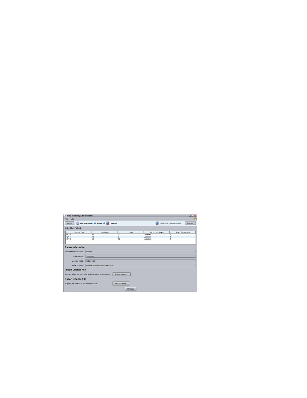
1. Launch the Interplay Administrator on the Interplay Engine. This can be found at:
Start>Avid>Avid Interplay Access Utilities>Avid Interplay Administrator.
2. Log in using Interplay Production’s Administrator credentials.
3. From the main menu, select Server>Licenses.
4. Click the Import License button.
5. Navigate to the location of the license file (often provided on a USB drive).
6. Select the license file and click Open.
You should receive a message indicating that the license was successfully activated.
7. Log out and close the Interplay Administrator application.
For additional information on the Interplay Administrator, see the Interplay | Engine and
Interplay | Archive Engine Administration Guide.
19
Page 20

MCS 2.4 Installation and Configuration Guide
iNEWS Licensing
Creating User Accounts
Interplay Production User
If you will be connecting to an iNEWS system, MediaCentral UX will validate client licenses
against the iNEWS server(s). Additional client licenses might have been included with the
purchase of MCS. These licenses will need to be added to iNEWS.
See Appendix C: Configuring iNEWS for Integration with MediaCentral
This section will cover the creation of user accounts for use with:
Interplay Production
Avid ISIS
iNEWS
Interplay MAM
Media Composer Cloud
Create any user accounts applicable to your installation.
When integrating with Interplay Production, MediaCentral UX requires credentials to access the
Interplay Production database. This user should have Read/Write privileges to the entire
database (at minimum). For consistency purposes, this user and password should be the same
as the user you create on the Avid ISIS system.
for more information.
Decide upon the name and password for this user now. Suggested user name: MCSAdmin
1. Launch the Interplay Administrator on the Interplay Engine. This can be found at:
Start>Avid>Avid Interplay Access Utilities>Avid Interplay Administrator.
2. Log in using Interplay Production’s Administrator credentials.
3. From the main menu, select User Management>User Management.
4. If multiple User Groups are created, highlight the User Group on the left under which you
want to create your new user. Example: Administrators
5. Click the Create User button at the top of the window.
6. Enter a name and password.
7. Verify that the MediaCentral UX Admin user has at least Read/Write access to the entire
database. Administrator-level access is not required, but recommended.
8. Click Apply.
9. Close the Interplay Administrator.
For additional information on users creation in Interplay Production, see the Interplay | Engine
and Interplay | Archive Engine Administration Guide.
20
Page 21
MCS 2.4 Installation and Configuration Guide
Avid ISIS User
When integrating with Interplay Production, MediaCentral UX requires credentials to access the
media on the ISIS system to enable playback and allow for the creation of voice-over media. For
consistency purposes, this user and password should be the same as the user you create on the
Interplay Production system.
Decide upon the name and password for this user now. Suggested user name: MCSAdmin
1. Launch the ISIS Management Console page by opening a web browser and navigating to one
of the following:
ISIS 5500: http://System Director hostname
ISIS 7500: https://System Director hostname:5015
Note: In a failover configuration, use the virtual System Director hostname.
Alternatively, the IP address of the System Director (or virtual System Director) can also
be used.
2. Log in using the ISIS Administrator credentials.
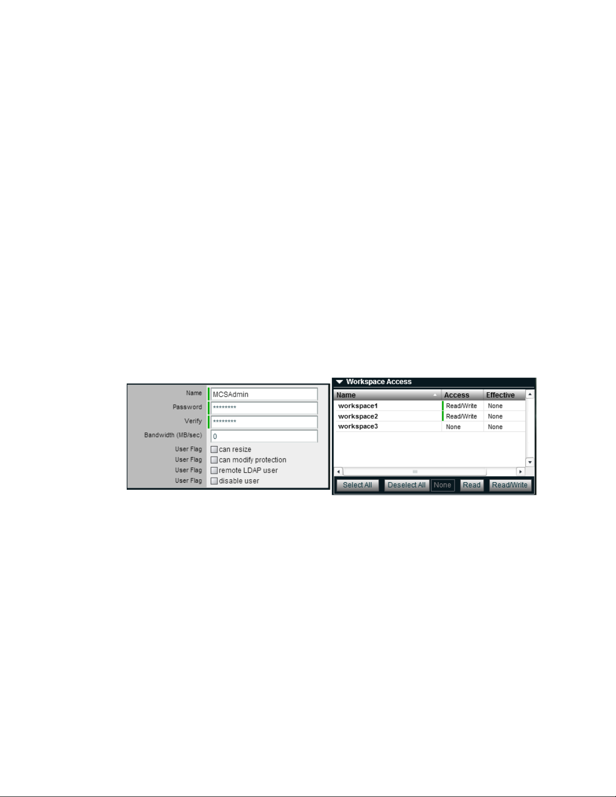
3. From the main menu, select System>Users.
4. Click the New button to create a new user.
5. Give the user a name and password.
6. Under Workspace Access, assign privileges to all indexed workspaces. At minimum, the user
needs Read access to all workspaces indexed by the Interplay Media Indexer and
Read/Write access to the workspace where voice-overs will be recorded (workspace defined
in the Interplay Administrator> Interplay Application Settings).
7. Click Apply to create the user account.
8. Close the ISIS Management Console.
Note: If you are connecting to multiple ISIS systems, ensure the same user/password is
created on each ISIS.
For additional information on users creation in Interplay Production, see the Avid | ISIS
Administration Guide.
21
Page 22

MCS 2.4 Installation and Configuration Guide
Avid iNEWS User
Interplay MAM User
Media Composer Cloud User
When integrating with iNEWS, the MCS Administrator requires access to the iNEWS database.
This can be accomplished by creating a custom user account (superuser rights not required) or
by associating the Administrator with an existing iNEWS account.
Decide upon the name and password for this user now. Suggested user name: MCSAdmin
For instructions on creating a custom iNEWS user account for MediaCentral UX, see the Avid
iNEWS Setup and Configuration Guide.
If you are integrating with MCS as a player for an Interplay MAM system, a specialized user must
be created within the MCS user database.
Decide upon the name of this custom user now. Suggested user name: MAMuser
For details on creating this user, see Configuring MCS for Interplay MAM on page 107
When installing Interplay MAM, a special user account is created on the MAM system. This user
is identified as: “Service-Ics” with password “Avid123”. If you will be installing the MAM
Connector software for MediaCentral UX, this “Service-Ics” is used in the System Settings.
For details on configuring the MAM Connector System Settings, see
Connector on page 157.
For more information on this user and setting, see the Avid MediaCentral | UX Administration
Guide.
Configuring the MAM
.
When integrating with Media Composer Cloud, a custom, matching user account needs to be
added to the Interplay Administrator (Application Database Settings) and to the MediaCentral
UX System Settings (ICPS>Player tab).
When added to the MediaCentral UX System Settings, this account is automatically added as an
MCS user and assigned a special “Playback-Only Client” user role. This will appear in the Users
Layout under Users>Unassigned>Playback-Only.
Rules regarding the specialized user account:
This must be a unique user created solely for this purpose. Do not use the same user
you created to log into Interplay Production and Avid ISIS.
Do not use an account that already exists as a Central User. It must be a new user.
This user should not be created as an Interplay Production or an ISIS user.
Remember that MCS runs on Linux. Both passwords and user accounts are case
sensitive.
Decide upon the name of this custom user now. Suggested user name: cloud
For more information on this user, see the Media Composer | Cloud Installation and
Configuration Guide.
22
Page 23
MCS 2.4 Installation and Configuration Guide
Adjusting Interplay Production Settings
When integrating with Interplay Production, MCS will check with the Interplay Engine for various
settings. This section is particularly important for sites requiring STP workflows or integrations
with Media Composer Cloud.
1. Launch the Interplay Administrator on the Interplay Engine. This can be found at:
Start>Avid>Avid Interplay Access Utilities>Avid Interplay Administrator
2. Log in using Interplay Production’s Administrator credentials.
3. From the main menu, select Application Settings>Application Database Settings. Adjust the
following:
a. Format – Video Format: This setting determines the default video format for
sequences created in MediaCentral UX. Select a specific video format from the
menu or leave the default selection, “Any”. If you select Any, MediaCentral UX
determines the video format by using the format of the first clip that the user adds
to the sequence.
b. Audio – General Settings: Ensure a Media Creation Workspace is selected.
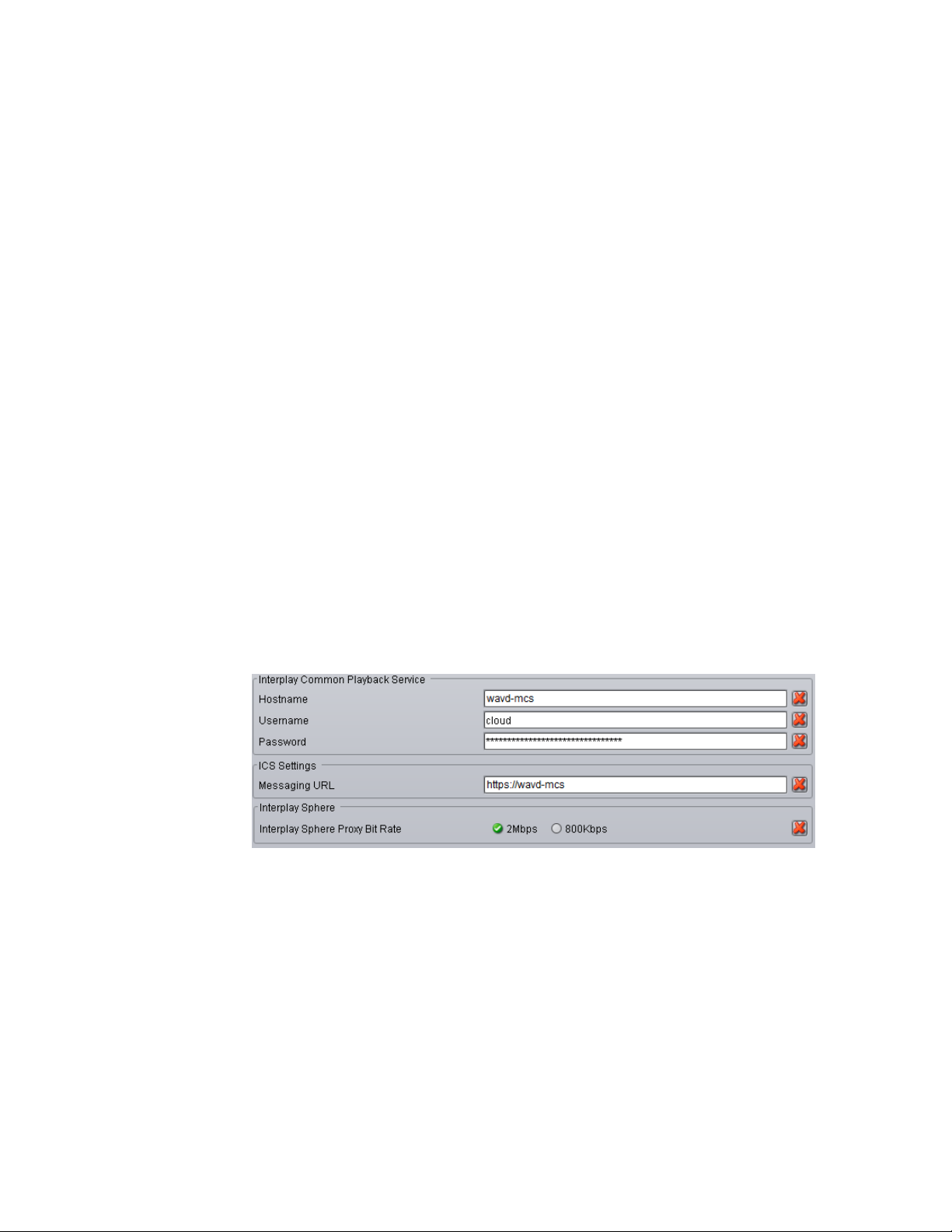
c. Interplay Common Playback Service (Cloud workflow only):
i. Hostname: Enter the hostname of the MCS server. In the case of a cluster,
enter the virtual MCS hostname.
ii. Username / Password: Specify a custom user and password that can be used
to communicate with MediaCentral UX. This same user / password will be
entered in the MediaCentral UX System Settings under the ICPS>Player tab.
This must be a unique user created solely for this purpose.
d. ICS Settings – Messaging URL: This setting enables a messaging workflow between
MCS and Media Composer. Enter the hostname of the MCS server in the form of a
URL. In the case of a cluster, enter the virtual MCS hostname.
e. Interplay Sphere (Cloud workflow only): The proxy setting used with Media
Composer Cloud is shown here for legacy purposes only. The proxy settings were
moved to “Application Settings>Media Composer | Cloud Settings” in Interplay
Production v3.1.
4. Click Apply.
5. If you are integrating with Media Composer Cloud, you should also configure the Application
Settings>Media Composer | Cloud Settings. See the Media Composer | Cloud Installation
and Configuration Guide for additional details.
23
Page 24
MCS 2.4 Installation and Configuration Guide
Adding the MediaCentral UX Version to Avid iNEWS
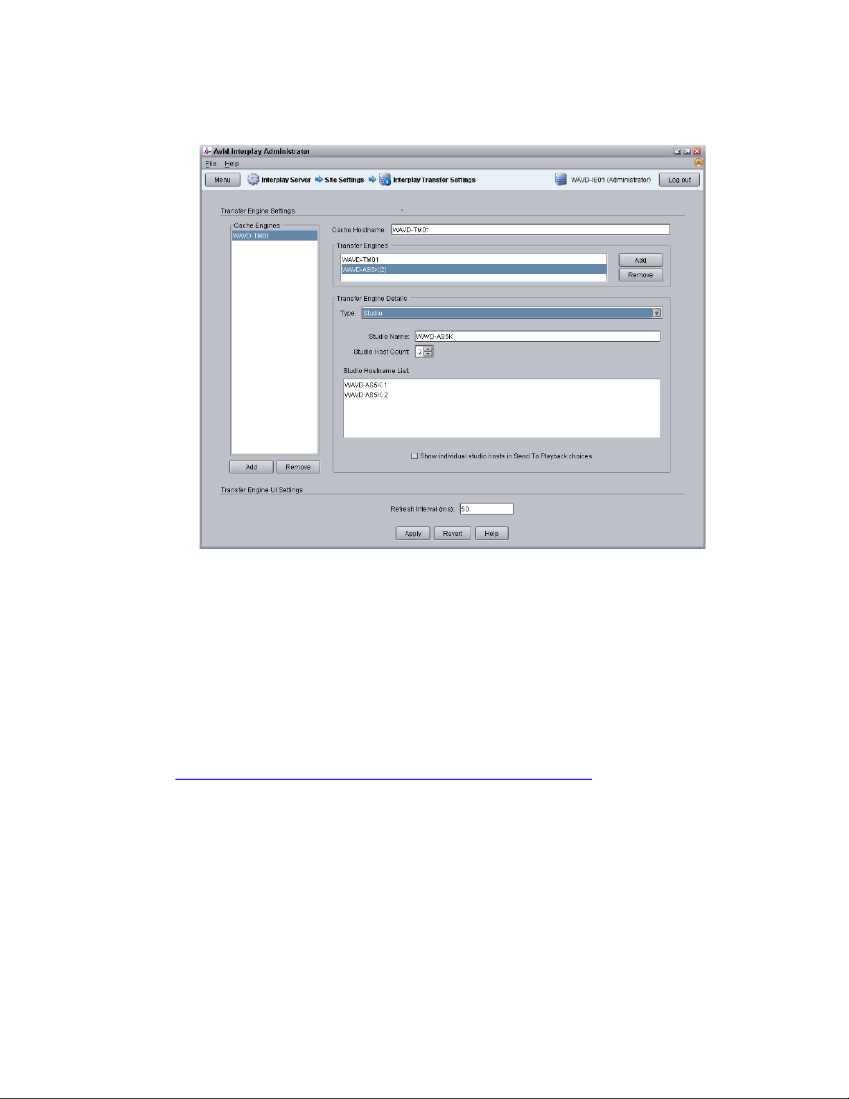
6. From the main menu, select Site Settings>Interplay Transfer Settings. MediaCentral will poll
this setting for configured Transfer Engines and AirSpeed servers when creating STP profiles.
7. Click Apply.
Before connecting MediaCentral UX to iNEWS, the MediaCentral UX Client version must be
added to the iNEWS SYSTEM.CLIENT.VERSIONS file.
Refer to the Avid MediaCentral Platform Services ReadMe for the correct version number for
your installation.
See Appendix C: Configuring iNEWS for Integration with MediaCentral
adding the version number to iNEWS.
for instructions on
24
Page 25

MCS 2.4 Installation and Configuration Guide
Installing the MediaCentral Distribution Service
The MediaCentral Distribution Service (MCDS) is a lightweight required for Send to Playback
(STP) operations. It analyzes the STP request and determines if additional actions are required
before sending the media to the playback device (AirSpeed, Transfer Engine, other). An
Interplay Transcode provider is required for STP operations requiring audio mixdowns (stereo
audio tracks) or video mixdowns (sequences with dissolves). An Interplay STP Encode provider
is required when using Long GOP media.
MCDS is not used if you are sending an asset directly to Transcode or Delivery. MCDS is not
used in iNEWS-only configurations.
The following guidelines apply to installing MCDS:
Supported on Windows 7 64-bit and Windows Server 2012.
o If you are running Windows Server 2012, you must install the Windows Desktop
Experience feature. For more information and installation procedures, see the Interplay
| Production Dell and HP Server Support guide at:
http://avid.force.com/pkb/articles/en_US/readme/Avid-Interplay-Production-V3-3-xDocumentation
o If you are running Windows 7 N, Windows Media Player must be manually installed. For
more information on “N” versions of Windows, see:
http://windows.microsoft.com/en-us/windows7/products/what-is-windows-7-n-edition
Requires a minimum of 512MB of RAM and approximately 380MB of hard drive space on the
host server.
Ensure that all enabled network adapters on both the system hosting the MCDS and the Interplay
Production Services Engine are fully routable to each other.
Can be installed on a server hosting other services or applications, such as the Interplay
Production Services Engine, Interplay Transcode Provider, Interplay Transfer Engine, etc.
Must be installed on a system that has the ISIS Client software installed.
Must not be installed on an Interplay Production Engine or Interplay Archive Engine.
As of Interplay Production 3.2, MCDS should not be installed on a Media Indexer server as the
two systems risk sharing network port 8443.
For redundancy purposes, MCDS can be installed on two systems. Installing a second instance
of MCDS does not provide load-balancing functionality. You will configure MediaCentral UX to
find the installed instance(s) of MCDS later in this document.
In MediaCentral UX 1.x, the MCDS service used port 8080 for normal http communication. In
MediaCentral UX v2.0 / MCDS v3.1, the port changed to 8890. This change allows MCDS to be
installed on the same server as the Production Services Engine (if desired). Port 8443 is used for
http security protocol.
Versions of MCDS prior to v3.3 required the Interplay Service Framework (32 or 64bit) software
to be installed on the system hosting MCDS. As of v3.3, this is no longer a requirement.
MCDS v3.3 cannot be installed on an Interplay Production Transcode provider or STP Encode
provider. This limitation has been resolved for MCDS v3.4.
For additional information on MCDS version compatibility, see the Avid Knowledge Base:
http://avid.force.com/pkb/articles/en_US/compatibility/Avid-Video-Compatibility-Charts
25
Page 26

MCS 2.4 Installation and Configuration Guide
Creating the MCS Installation USB Drive
Preparing the Installation Drive for the HP ProLiant Gen9
Installing the MediaCentral Distribution Service:
1. Launch the MCDS installer on your desired system(s).
2. Proceed through the installation and accept the defaults.
You may be asked to install prerequisite requirements such as Microsoft Visual C++.
3. Once installed, use Windows Computer Management to verify that the service is “Started”
and the Startup Type is configured as “Automatic”.
The MCS installation is initiated from a bootable USB drive that contains the OS (Red Hat
Enterprise Linux) and the MCS software. For this procedure you require the following items:
A Windows-based computer
The MCS installation package (MediaCentral_Services_<version>_Linux.zip)
RHEL installation image (.iso) file
A 16GB or larger USB drive
Note: Avid has been informed of problems using USB drives from some vendors. If the
server does not boot from the USB drive, or fails to complete the boot, try using a drive
from another vendor or a drive with a larger capacity (32GB).
This procedure uses an application called “ISO to USB” to create a bootable USB drive containing
the required RHEL operating system and MCS files. Do not simply drag and drop installation files
onto the USB drive as this will not create the correct file structure needed to successfully install
MCS.
Note: Since “ISO to USB” creates a bootable drive, Avid recommends only connecting the
USB drive you plan to use to the Windows system. If you have more than one USB drive
inserted, make sure you choose the right one when performing this procedure.
The procedure for creating the MCS installation drive on a ProLiant Gen9 server differs from that
of other installations. Make sure you follow the customized instructions for your server type.
This section contains three procedures:
Preparing the MCS Installation USB Drive
Copying the Storage Controller Driver to the USB Drive
Preparing the MCS Installation USB Drive:
1. Log into a Windows system.
2. Connect the USB drive to the Windows system and give it a few moments to be
recognized.
3. Use Windows Disk Management to format the USB drive as a FAT32 volume.
26
Page 27
MCS 2.4 Installation and Configuration Guide
RAID 1 and RAID 5
sda
sdb
sdc
RAID 1 only
sda
--
sdb
4. Extract the contents of the MediaCentral_Services_<version>_Linux.zip file to the
desktop (or your preferred destination directory).
5. Open the newly created MediaCentral_Services_<version>_Linux folder.
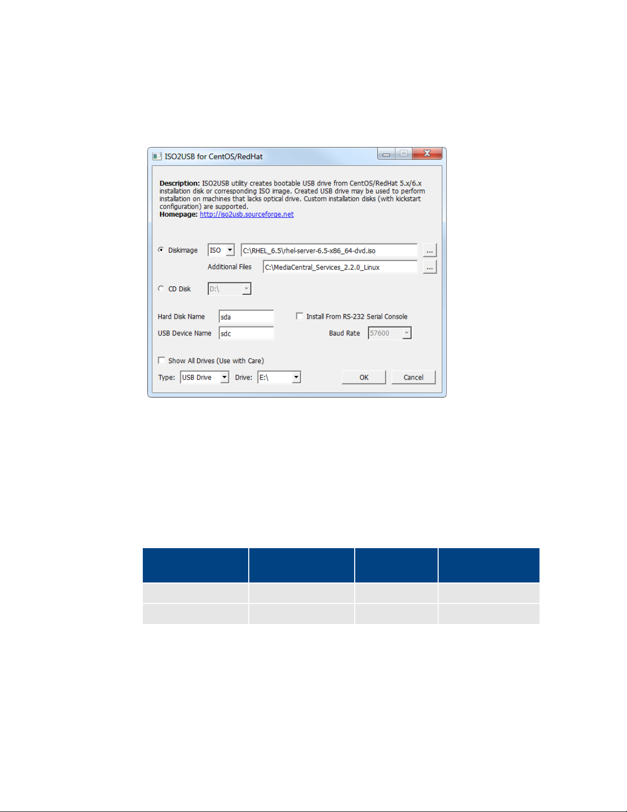
6. Double-click iso2usb.exe to launch the application.
7. Choose the Diskimage radio button then navigate to the RHEL image (.iso) file (named
rhel-server-6.5-x86_64-dvd.iso or similar).
Note: Make sure the RHEL image (.iso) file is accessible locally (preferable) or over the
network from your computer.
8. In the “Additional Files” field, navigate to the MediaCentral_Services_<version>_Linux
folder and click the “Select Folder” button.
9. Use the table below to verify that the Hard Disk Name and USB Device Name fields are
correct for your deployment.
RAID Configuration RAID 1
(“Hard Disk Name”)
RAID 5 USB
(“USB Device Name”)
For example, for a system deploying both RAID 1 and RAID 5 volumes, enter the
following values in the dialog:
• Hard Disk Name: sda
27
• USB Device Name: sdc
Important: For those familiar with earlier HP servers, the HP ProLiant Gen9 server
identifies the RAID 1, RAID 5, and the USB drive with different device names.
Page 28
MCS 2.4 Installation and Configuration Guide
10. Verify the USB Drive letter or use the pull-down menu to select a new drive letter.
11. Click OK in the main dialog.
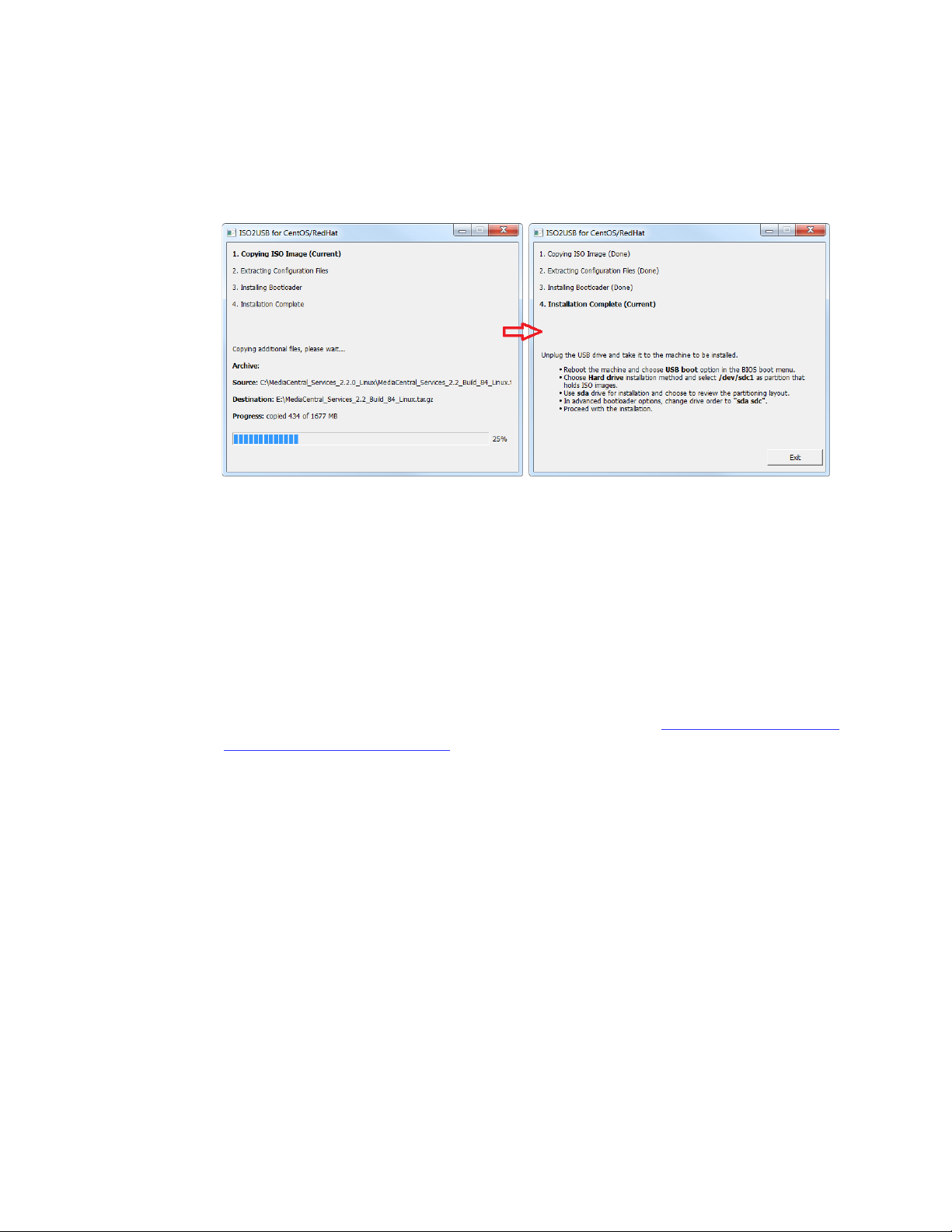
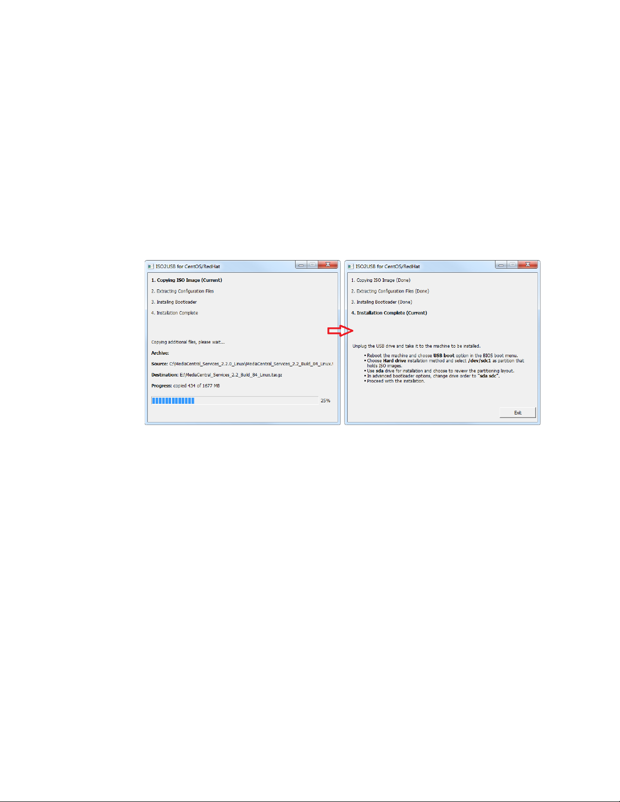
12. A process begins to copy the RHEL image (.iso) file and the MCS installation files to the
USB drive.
This process takes 10-20 minutes. Once complete, the USB drive has everything it needs
to complete the RHEL and MCS installation.
Note: Copying the RHEL image (.iso) file to the USB drive is a one-time process. To install
MCS on more than one server, or to re-install MCS, you do not need to repeat these
steps.
13. Click Exit to close the application.
Copying the Storage Controller Driver to the USB Drive:
1. If you have not already obtained the RAID controller drive, see
Storage Controller Driver
for the HP ProLiant Gen9 Server for location and download instructions.
2. With the Installation USB drive still plugged in to the Windows laptop or desktop, copy
the RAID controller driver ISO to the root directory on the drive:
dd-hpsa-18216-x86_64.iso
3. Rename the ISO:
• Old Name: dd-hpsa-18216-x86_64.iso
• New Name: z_dd-hpsa-18216-x86_64.iso
Renaming the driver ISO is essential, since the installation script attempts to mount the
first ISO it finds as the RHEL ISO. If you do not rename it, the installation will fail.
28
Page 29
MCS 2.4 Installation and Configuration Guide
Preparing the Installation Drive for HP Gen8 and Dell Servers
Follow this procedure only if you are installing MCS software components on supported HP
Gen8 or Dell servers.
Preparing the MCS Installation USB Drive:
1. Log into a Windows system.
2. Connect the USB drive to the Windows system and give it a few moments to be
recognized.
3. Use Windows Disk Management to format the USB drive as a FAT32 volume.
4. Extract the contents of the MediaCentral_Services_<version>_Linux.zip file to the
desktop (or your preferred destination directory).
5. Open the newly created MediaCentral_Services_<version>_Linux folder.
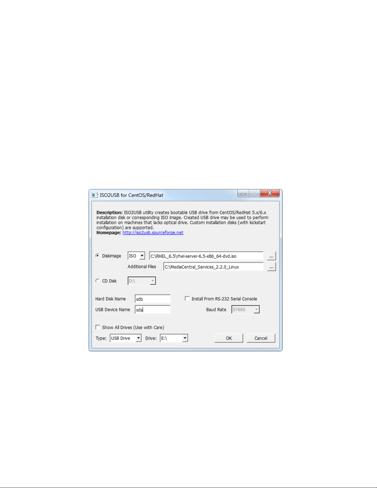
6. Double-click iso2usb.exe to launch the application.
7. Choose the Diskimage radio button then navigate to the RHEL image (.iso) file (named
rhel-server-6.5-x86_64-dvd.iso or similar).
Note: Make sure the RHEL image (.iso) file is accessible locally (preferable) or over the
network from your computer.
8. In the “Additional Files” field navigate to the MediaCentral_Services_<version>_Linux
folder and click the “Select Folder” button.
29
Page 30
MCS 2.4 Installation and Configuration Guide
9. Verify the Hard Disk Name and USB Device Name fields are as follows:
• Hard Disk Name: sdb
• USB Device Name: sda
Note: If the drive names are not configured properly in the kickstart file, you could
encounter errors in the deployment process. Example: “Error Partitioning: Could not
allocate requested partitions: not enough free space on disks.”
10. Verify the USB Drive letter or use the pull-down menu to select a new drive letter
11. Click OK in the main dialog.
12. A process begins to copy the RHEL image (.iso) file and the MCS installation files to the
USB drive.
This process takes 10-20 minutes. Once complete, the USB drive has everything it needs
to complete the RHEL and MCS installation.
Note: Copying the RHEL image (.iso) file to the USB drive is a one-time process. To install
MCS on more than one server, or to re-install MCS, you do not need to repeat these
steps.
30
Page 31

MCS 2.4 Installation and Configuration Guide
PART II: BIOS & RAID CONFIGURATION
31
Page 32

MCS 2.4 Installation and Configuration Guide
Chapter Overview
1
Changing BIOS Settings
15 min
Each of the supported server types require adjustments to the system BIOS.
2
Configuring the Onboard RAID
varies
Each of the supported server types features different methods for creating
The purpose of this chapter is to prepare the server hardware for the installation of RHEL and
MCS.
The following table describes the topics covered in this chapter.
Step Task Time Est.
This section covers:
• HP ProLiant DL360 Gen9
• HP ProLiant DL360p Gen8
• Dell PowerEdge R620 / R630
and working with the onboard RAID controllers. This section covers:
• HP ProLiant DL360 Gen9
• HP ProLiant DL360p Gen8
• Dell PowerEdge R620 / R630
32
Page 33

MCS 2.4 Installation and Configuration Guide
Changing BIOS Settings
Configuring the BIOS on the HP ProLiant DL360 Gen9
This section provides information on the BIOS settings for the following Avid qualified servers:
• Configuring the BIOS on the HP ProLiant DL360 Gen9
• Configuring the BIOS on the HP ProLiant DL360p Gen8
• Configuring the BIOS on the Dell PowerEdge R620 / R630
Servers are frequently shipped with BIOS settings configured for a power-saving mode. MCS
makes intensive use of the server’s CPUs and memory, especially when under heavy load.
Configuring the server to operate at maximum performance will ensure operational efficiency.
To ensure the smooth installation of RHEL and MCS, the system clock must be set within the
BIOS. When configuring an MCS cluster, setting the system clocks accurately is particularly
important.
1. Power up the server.
2. When the console displays the option to enter the “System Utilities” menu, press F9. The
BIOS responds by highlighting the F9 button at the bottom of the screen.
33
Page 34

MCS 2.4 Installation and Configuration Guide
3. Select System Configuration and press Enter.
4. Select BIOS/Platform Configuration (RBSU) and press Enter.
5. Select Boot Options and press Enter.
34
Page 35

MCS 2.4 Installation and Configuration Guide
6. Select Boot Mode and press Enter.
You may see a warning message (shown below) indicating that Boot Mode changes will
require a reboot. Press Enter to accept this warning.
7. A smaller selection box will appear. Select Legacy BIOS Mode and press Enter.
35
Page 36

MCS 2.4 Installation and Configuration Guide
8. Press ESC to navigate back to the BIOS/Platform Configuration (RBSU) screen.
9. Select Power Management and press Enter.
10. Press Enter to select HP Power Profile.
11. A smaller selection box will appear. Select Maximum Performance and press Enter.
36
Page 37

MCS 2.4 Installation and Configuration Guide
12. Press ESC to navigate back to the BIOS/Platform Configuration (RBSU) screen.
13. Select Date and Time and press Enter.
14. Set the date (mm-dd-yyyy) and time (hh:mm:ss).
15. Press ESC to navigate back to the BIOS/Platform Configuration (RBSU) screen.
16. Press F10 to save.
17. Press ESC to navigate back to the System Configuration screen.
If prompted, select “Y” to save changes and exit.
18. Press ESC to navigate back to the System Utilities screen.
19. Select Reboot the System and press Enter.
The server reboots with new options.
Proceed to Configuring the Onboard RAID on page 41
37
.
Page 38

MCS 2.4 Installation and Configuration Guide
Configuring the BIOS on the HP ProLiant DL360p Gen8
1. Power up the server.
2. When the console displays the option to enter the “System Utilities” menu, press F9. The
BIOS responds by highlighting the F9 button at the bottom of the screen.
The ROM-Based Setup Utility appears after a few moments.
3. Select Power Management Options and press Enter.
Power Management options are displayed.
4. Choose HP Power Profile.
Power Profile options are displayed.
5. Choose Maximum Performance.
You are returned to the Power Management options menu.
6. Press Esc to return to main menu.
7. Select Date and Time and press Enter.
Date and Time options are displayed.
Set the date (mm-dd-yyyy) and time (hh:mm:ss).
8. Press Enter to save the changes and return to the Setup Utility menu.
9. Exit the Setup utility. Press Esc and F10 to save.
The server reboots with new options.
Proceed to Configuring the Onboard RAID on page 41
.
38
Page 39

MCS 2.4 Installation and Configuration Guide
Configuring the BIOS on the Dell PowerEdge R620 / R630
This process includes steps to ensure your MCS Installation USB drive is first in the boot order.
Prior to beginning this process, ensure your MCS Installation drive is available.
For instructions on creating the boot drive, see
Preparing the Installation Drive for HP Gen8
and Dell Servers on page 29.
1. Connect your MCS Installation USB drive to one of the Dell’s USB ports.
2. Power up the server.
3. Press F2 to enter the BIOS.
4. Select System BIOS
5. Select System Profile Settings.
6. Select the Performance profile from the pull-down menu and click Back.
Note: There are three “Performance” profiles. Once of them specifically says “Performance”
and not “Performance Per Watt.”
7. Select System BIOS Settings
39
Page 40

MCS 2.4 Installation and Configuration Guide
8. Select Boot Settings
9. Select BIOS Boot Settings
10. Select Hard-Disk Drive Sequence
11. In the Change Order window, use the + or – keys to move the USB boot drive to the top of
the list and click OK.
12. Click Back to exit the page and to exit the System BIOS Settings page.
13. Select Miscellaneous Settings
14. Change the System Time and System Date by highlighting the appropriate field and pressing
Enter.
15. A window will appear with pull-down menu options. Click OK when done.
16. You are asked to confirm the changes.
A “Success” dialog indicates the settings were saved.
17. Click Back and Finish to return to the main System Setup screen.
Note: When ordering a Dell server, an ”Internal SD Card Port” is an optional component. This
device will appear to Linux as a media device and it will automatically be assigned a device
name. This can interfere with the RHEL / MCS deployment. If you have an ”Internal SD Card
Port”, temporarily disable it in the BIOS: System BIOS > Integrated Devices > Internal SD Card
Port > Off. The device can be re-enabled once you have completed the MCS installation.
Proceed to Configuring the Onboard RAID on page 41
40
.
Page 41

MCS 2.4 Installation and Configuration Guide
Configuring the Onboard RAID
HP ProLiant DL360 Gen9 RAID Configuration
This section provides information on the RAID configuration for the following Avid qualified
servers:
• HP ProLiant DL360 Gen9 RAID Configuration
• HP ProLiant DL360p Gen8 RAID Configuration
• Dell PowerEdge R620 / R630 RAID Configuration
RAID 1: All MCS implementations require a RAID 1 (mirror) for the system (OS) drive. This RAID
provides redundancy in the event of HD failure.
RAID 5: Certain deployments also require additional disks configured as a RAID 5 (data striping
with parity blocks) for caching file data. This RAID provides redundancy and increased
performance.
See the MediaCentral Platform Services Concepts and Clustering Guide for more information on
RAID configurations.
In this step you configure two of the HD drives in the server enclosure as a RAID Level 1 – a
mirrored RAID – where the RHEL and MCS software will be installed. This is done using the
Option ROM Configuration for Arrays utility, in the HP server’s BIOS.
If applicable, configure the remaining HD drives in the server enclosure as a RAID Level 5. In a
RAID 5 data is automatically distributed across all the disks in the RAID for increased
performance and redundancy. This is done using the Option ROM Configuration for Arrays
utility, in the HP server’s BIOS.
Note: If the list of available disks does not appear as expected, it may be that a RAID has
already been created. Deleting a RAID destroys all the data it contains, so verify it is safe
to do so first.
Note: This document provides instructions for creating a media cache volume as a
RAID 5 using multiple disks in the server enclosure. However, other configurations are
possible, including two drives in a RAID 1 configuration, or a single drive. For details, see
the MediaCentral Platform Services Hardware Guide.
41
Page 42

MCS 2.4 Installation and Configuration Guide
Configuring the HP ProLiant DL360 Gen9 RAID 1
Note: The RAID configuration process will immediately transition into the Red Hat / MCS
installation. It is recommended that you connect your MCS Installation USB drive to the server at
this time.
1. Reboot the server and press F10 to select Intelligent Provisioning.
2. Select Perform Maintenance.
3. Select HP Smart Storage Administrator (SSA)
4. At the “Welcome to HP Smart Storage Administrator” screen, select Smart Array P840
from left side menu.
5. Select Create Array under “Actions”.
42
Page 43
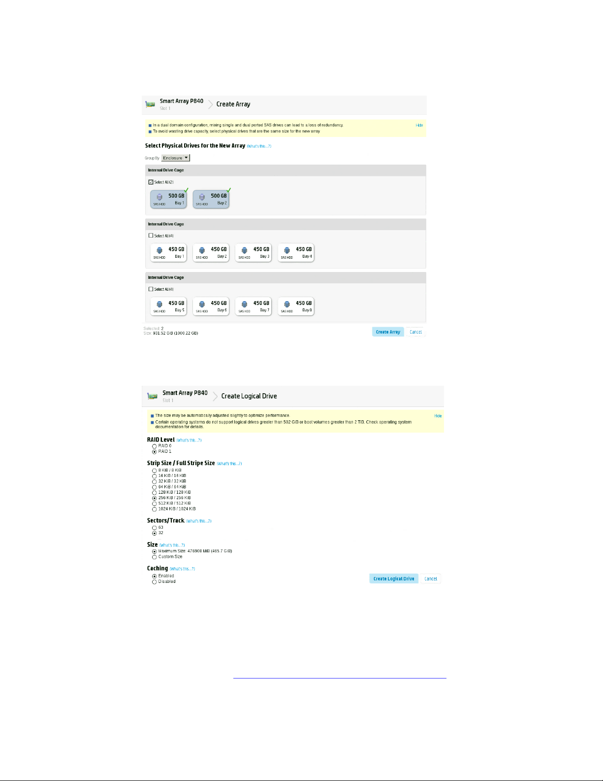
MCS 2.4 Installation and Configuration Guide
6. Select both 500GB Drives then select Create Array.
7. Verify the following are selected: RAID 1, 256 KiB / 256 KiB Stripe Size, 32 Sectors,
Maximum Size, Caching Enabled.
8. Click Create Logical Drive.
9. You will receive a message indicating the “Logical Drive was successfully created.” Click
Finish to complete the RAID 1 creation process.
Note: Do not press the Escape key to exit, since this reboots the server.
If applicable, proceed to Configuring the HP ProLiant DL360 Gen9 RAID 5 on page 44
43
.
Page 44
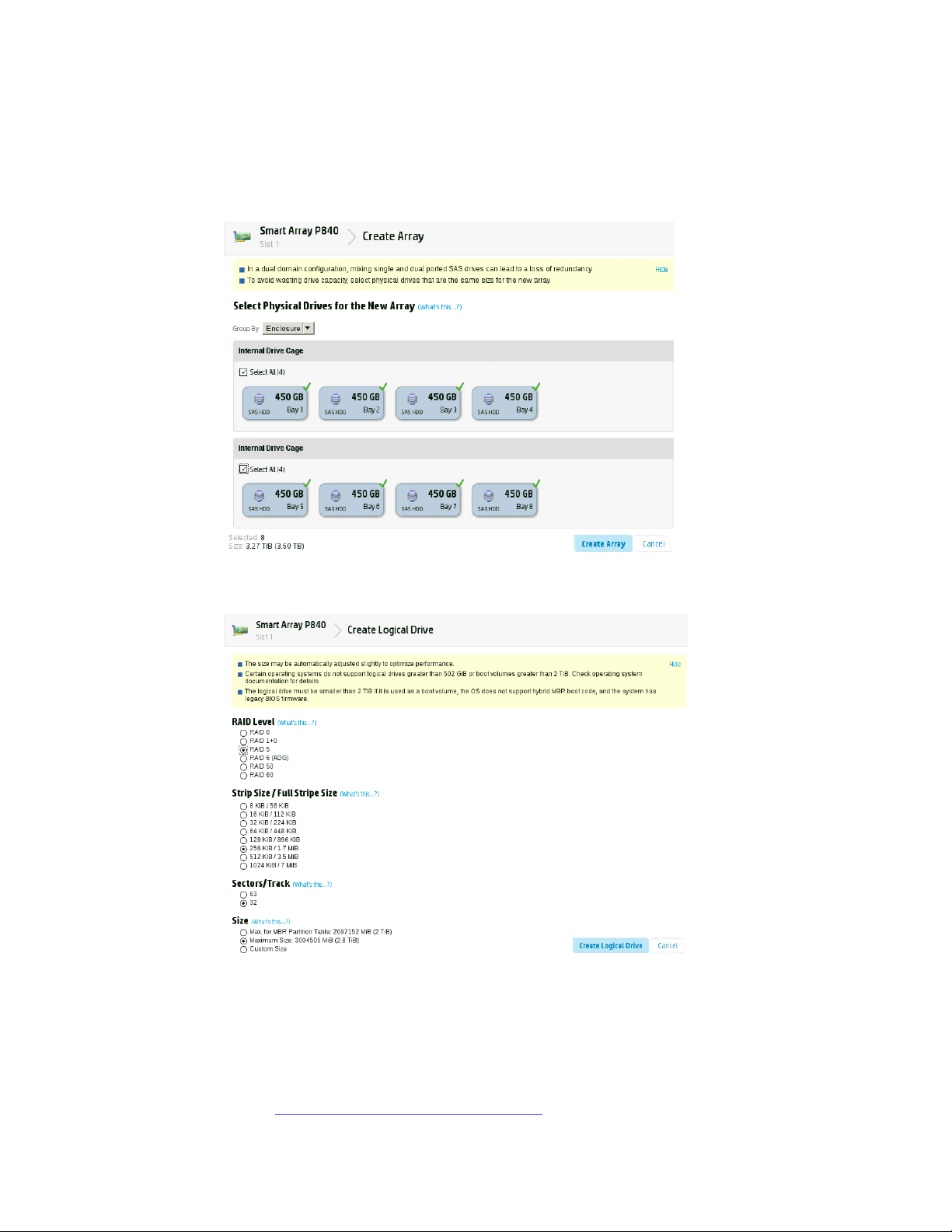
MCS 2.4 Installation and Configuration Guide
Configuring the HP ProLiant DL360 Gen9 RAID 5
This process assumes you are continuing from the RAID 1 creation process.
1. Select Create Array under “Actions”.
2. Select all eight 450GB Drives then select Create Array.
3. Verify the following are selected: RAID 5, 256 KiB / 1.7 MiB Stripe Size, 32 Sectors,
Maximum Size, Caching Enabled.
4. Click Create Logical Drive.
5. You will receive a message indicating the “Logical Drive was successfully created.” Click
Finish to complete the RAID 5 creation process.
6. Click the “X” (top right) to exit. Confirm the exit by clicking “OK” when prompted.
7. Click the “Power” button (top right) to exit. Select “Reboot” when prompted.
Proceed to Installing RHEL and the MCS Software on page 55
44
.
Page 45

MCS 2.4 Installation and Configuration Guide
HP ProLiant DL360p Gen8 RAID Configuration
Configuring the HP ProLiant DL360p Gen8 RAID 1
In this step you configure two of the HD drives in the server enclosure as a RAID Level 1 – a
mirrored RAID – where the RHEL and MCS software will be installed. This is done using the
Option ROM Configuration for Arrays utility, in the HP server’s BIOS.
If applicable, configure the remaining HD drives in the server enclosure as a RAID Level 5. In a
RAID 5, data is automatically distributed across all the disks in the RAID for increased
performance and redundancy. This is done using the Option ROM Configuration for Arrays
utility, in the HP server’s BIOS.
Note: If the list of available disks does not appear as expected, it may be that a RAID has
already been created. Deleting a RAID destroys all the data it contains, so verify it is safe
to do so first.
Note: This document provides instructions for creating a media cache volume as a
RAID 5 using multiple disks in the server enclosure. However, other configurations are
possible, including two drives in a RAID 1 configuration, or a single drive. For details, see
the “MediaCentral Platform Services Hardware Guide”.
Note: The RAID configuration process will immediately transition into the Red Hat / MCS
installation. It is recommended that you connect your MCS Installation USB drive to the server at
this time.
1. Reboot the server and press any key (spacebar recommended) when prompted to
display the HP ProLiant “Option ROM” messages.
Note: Do not press F9 or F11. Press any key other than F9 or F11 (spacebar
recommended).
Detailed messages now appear as the server boots up.
45
Page 46

MCS 2.4 Installation and Configuration Guide
2. As soon as you see the prompt to “Press <F8> to run the Option ROM Configuration for
Arrays Utility”, press F8.
Note: The prompt to press F8 can flash by quite quickly. If you miss it, reboot and try
again.
3. From the Main Menu, select Create Logical Drive.
46
Page 47

MCS 2.4 Installation and Configuration Guide
4. Select the following two HD drives in “Available Physical Drives”:
• Box 1, Bay 1
• Box 1, Bay 2
5. Deselect all the other available HD drives (if any).
6. Ensure RAID 1 is selected in the “RAID Configurations” section.
Note: In older firmware versions, the choice presented may be RAID 1+0. Since you
are only using two HD drives, this is identical to a RAID 1.
7. Ensure Disable (4GB maximum) is selected in the “Maximum Boot partition” section.
8. Ensure nothing is selected in the “Parity Group Count” section.
9. Ensure nothing is selected in the “Spare” section.
10. Press Enter to create the logical drive.
A message appears summarizing the RAID 1 setup.
11. Press F8 to save the configuration.
A message appears confirming the configuration has been saved.
12. Press Enter to finalize the RAID 1 setup.
Note: Do not press the Escape key to exit, since this reboots the server.
If applicable, proceed to Configuring the HP ProLiant DL360p Gen8 RAID 5 on page 48
.
47
Page 48

MCS 2.4 Installation and Configuration Guide
Configuring the HP ProLiant DL360p Gen8 RAID 5
This process assumes you are continuing from the RAID 1 creation process.
1. From the Main Menu, select Create Logical Drive.
2. Select the drives to be included in the RAID 5 in the “Available Physical Drives” section.
• Box 1 Bays 3-8 (typical configuration)
3. Ensure RAID 5 is selected in the “RAID Configurations” section.
4. Ensure Disable (4GB maximum) is selected in the “Maximum Boot partition” section.
5. Ensure nothing is selected in the “Parity Group Count” section.
48
Page 49

MCS 2.4 Installation and Configuration Guide
6. Ensure nothing is selected in the “Spare” section.
7. Press Enter to create the logical drive.
A message appears summarizing the RAID 5 setup.
8. Press F8 to save the configuration.
A message appears confirming the configuration has been saved.
9. Press Enter to finalize the RAID 5.
10. Press ESC to reboot the system.
Proceed to Installing RHEL and the MCS Software on page 55
.
49
Page 50

MCS 2.4 Installation and Configuration Guide
Dell PowerEdge R620 / R630 RAID Configuration
Verifying the PowerEdge Dell R620 / 630 RAID Configuration:
The Dell R620 / R630 servers ship with preconfigured RAID 1 and RAID 5 arrays. In this step you
verify the RAID configuration through the BIOS. Later you will use RHEL to ensure the RAID
arrays are cleared of existing data.
Two of the HD drives in the server are configured as a RAID Level 1 – a mirrored RAID – where
the RHEL and MCS software will be installed.
If applicable, the remaining drives in the server enclosure will be configured as a RAID Level 5. In
a RAID 5 data is automatically distributed across all the disks in the RAID for increased
performance and redundancy.
Note: This document provides instructions for creating a media cache volume as a
RAID 5 using multiple disks in the server enclosure. However, other configurations are
possible, including two drives in a RAID 1 configuration, or a single drive. For details, see
the “MediaCentral Platform Services Hardware Guide”.
Note: The RAID configuration process will immediately transition into the Red Hat / MCS
installation. If you do not already have the MCS Installation USB drive connected, connect it to
the server at this time.
1. (if necessary) Reboot the server and press F2 to enter the BIOS.
2. From the main System Setup screen, select Device Settings.
3. From the Device Settings menu, select Integrated RAID Controller Configuration Utility.
4. From the Configuration Options menu, select Virtual Disk Management.
50
Page 51
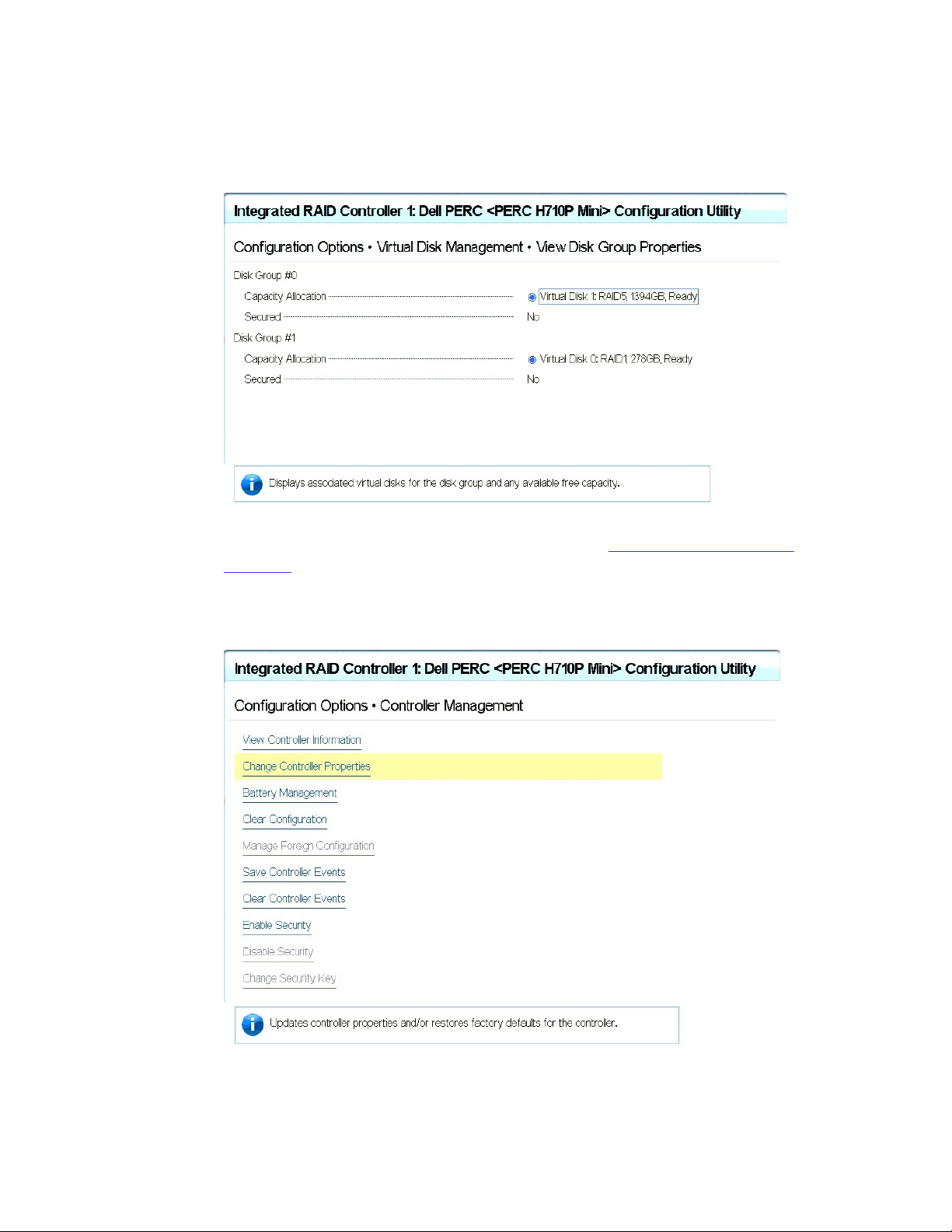
MCS 2.4 Installation and Configuration Guide
5. From the Virtual Disk Management menu, select View Disk Properties.
This window lists the configured RAID Groups on the server. You should see both a RAID
1 set and a RAID 5 set.
Note: If the preconfigured RAID arrays do not exist, see
Controller in Appendix A for information on creating the RAID.
Working with the Dell RAID
6. From the Configuration Options menu, select Controller Management.
7. From the Controller Management menu, select Change Controller Properties.
51
Page 52

MCS 2.4 Installation and Configuration Guide
8. Ensure the Set Bootable Device pull-down menu is configured for Virtual Disk 0: RAID 1
9. Return to the main System Setup screen.
10. Click Finish to reboot the system.
Proceed to Installing RHEL and the MCS Software on page 55
.
52
Page 53

MCS 2.4 Installation and Configuration Guide
PART III: SOFTWARE INSTAL LATION AND PREPARATION
53
Page 54
MCS 2.4 Installation and Configuration Guide
Chapter Overview
1
Installing RHEL and the MCS Software
5 min Provides some introductory information on the installation process.
2
Special Instructions for Dell Servers
10 min
Covers the deletion of any existing partitions on the Dell RAID arrays prior to
3
MCS Software Deployment
30 min
Covers the actual installation of RHEL and MCS.
4 Booting RHEL for the First Time
5 min
Covers keyboard layout configuration and a process for changing the default
5
Network Configuration
30 min Guides you through the configuration of all network-related settings.
6
Configure Date and Time Settings
15 min Configuration of Date, Time, Time Zone and NTP settings.
7 Creating the File Cache on the RAID
15 min If a RAID 5 array is used, this step finalizes the creation of the RAID 5.
8 Enable / Disable 3G and Edge Streams
2 min Instructions for enabling / disabling 3G and Edge streams.
9 Copying Software to the MCS Server
varies
While RHEL and MCS software is installed by the MCS Installation USB drive,
10
Security Updates
15 min
Information regarding Security Updates for RHEL.
11
Install Software Patches
15 min A reminder to install available software patches.
The purpose of this chapter is to assist you with the installation and configuration of the system
software.
The following table describes the topics covered in this chapter.
Step Task Time Est.
the installation of RHEL and MCS.
‘root’ user password.
additional software might be required.
54
Page 55

MCS 2.4 Installation and Configuration Guide
Installing RHEL and the MCS Software
This process will step you through the installation and configuration of an MCS server.
Caution: If you are in the process of upgrading from an earlier version of MCS — called ICS in
earlier releases — it is a fresh install, and will overwrite your current ICS settings and databases.
Before proceeding with the upgrade, back up your current settings:
Database: The ICS settings and database using the backup script (system-backup.sh)
provided. See
SSL Private Key(s): If you deployment makes use of CA-signed certificates, back up
private(s), regardless of the upgrade path.
Corosync Configuration File: If you configured ICS 1.4.x for unicast, you made changes to
the corosync configuration (corosync.conf) file. The installation script overwrites this file.
To preserve your changes, back up the file before beginning the upgrade, and restore it
after.
Note: For workflow details on upgrading to MCS 2.4 from an earlier release, see the MCS 2.4
Upgrading Guide, available from the Avid Knowledge Base
Backing up the MCS System Settings on page 139.
MCS 2.4 web page.
How to proceed:
If you are installing MCS on a Dell server, additional steps are required during the server
imaging process. Proceed to Special Instructions for Dell Servers on page 56
(the next
page).
If you are installing MCS on an HP server, proceed directly to MCS Software
Deployment on page 60.
55
Page 56

MCS 2.4 Installation and Configuration Guide
Special Instructions for Dell Servers
Dell servers are generally shipped with preconfigured RAID 1 and RAID 5 arrays. These RAID sets
include partitions that can interfere with the kickstart assisted software deployment. The
partitions must be deleted prior to starting the installation.
Deleting and recreating the RAID sets using the DELL BIOS utility does not erase data, nor does it
delete existing partitions. That is, deleting a RAID does not delete the partition table — unless
you initialize the disk at the same time. However, initializing the disk is a slow process.
In this procedure, you boot from the MCS Installation USB Drive and launch a RHEL “rescue”
session in order to examine the current system partitions and delete them.
If you are installing MCS on an HP server, proceed to MCS Software Deployment on page 60
1. Boot from the MCS Installation USB drive.
2. At the RHEL Welcome screen, select “Rescue Installed System”.
3. When prompted choose the language and keyboard.
4. Choose “Hard drive” as the rescue method. For the purposes of booting from a RHEL image,
the USB drive is considered a hard drive.
.
56
Page 57

MCS 2.4 Installation and Configuration Guide
5. Select the “/dev/sda1” partition (the USB drive). Leave the “Directory holding image” field
blank.
6. Select No in the Setup Networking window; as networking is not needed at this time.
7. Select “Skip” in the Rescue window.
57
Page 58
MCS 2.4 Installation and Configuration Guide
8. At the next screen, choose “shell Start shell” and select Ok.
9. At the system prompt, use the RHEL fdisk utility to examine the current partitions:
fdisk -cul
This command will display the available disks and partitions on the system. Use Shift-Pg Up
and Shift-Pg Down to view the entire output, since scroll bars will not be present in the
rescue shell.
In this case “sda” should be the USB boot drive, “sdb” should be the RAID 1 volume and
“sdc” should be the RAID 5 volume.
The following example shows information for “sdb” with three partitions (sdb1, sdb2, sdb3):
Disk /dev/sdb: 500.1 GB, 500074307584 bytes
255 heads, 63 sectors/track, 60797 cylinders, total 97670732 sectors
Units = sectors of 1 * 512 = 512 bytes
Sector size (logical/physical): 512 bytes / 512 bytes
I/O size (minimum/optimal): 512 bytes / 512 bytes
Disk identifier: 0xc755f5b0
Device Boot Start End Blocks Id System
/dev/sdb1 * 2048 1026047 512000 83 Linux
/dev/sdb2 1026048 42051583 20512768 8e Linux LVM
/dev/sdb3 42051584 976707583 467328000 8e Linux LVM
Additional entries for the filesystem (sdb4, sdb5) could be possible. Example:
Disk /dev/sdb: 598.9 GB, 598879502336 bytes
255 heads, 63 sectors/track, 72809 cylinders, total 11696828 sectors
Units = sectors of 1 * 512 = 512 bytes
Sector size (logical/physical): 512 bytes / 512 bytes
I/O size (minimum/optimal): 512 bytes / 512 bytes
Disk identifier: 0x930a8a0e
Device Boot Start End Blocks Id System
/dev/sdb1 * 2048 1026047 512000 83 Linux
/dev/sdb2 1026048 2050047 512000 83 Linux
/dev/sdb3 2050048 43075583 20512768 8e Linux LVM
/dev/sdb4 43075584 1169686527 563305472 5 Extended
/dev/sdb5 43077632 1169686527 563304448 8e Linux LVM
58
Page 59

MCS 2.4 Installation and Configuration Guide
You will need to delete the any partitions on the RAID 1 volume and the RAID 5 volume (if
applicable). This process will assume “sdb” is the RAID 1 and “sdc” is the RAID 5.
10. Use the RHEL fdisk utility to select the sdb volume:
fdisk /dev/sdb
11. Type: p to print the current filesystem partition table. This will show you a similar output
as the fdisk –cul command you used earlier.
12. Type: d to begin deleting the partitions.
13. You will be prompted to specify the partition to delete. Example: 1
Partition number (1-4): 1
14. Repeat the above two steps to delete the remaining “sdb” partitions.
15. Once complete, type p to print the partition table again. An empty partition table should
look like the following:
Device Boot Start End Blocks Id System
16. Type: w to write the changes to the partition table and exit the utility.
17. If you have a RAID 5 volume, repeat this process by specifying the RAID 5 “sdc” partition:
fdisk /dev/sdc
18. Repeat the above steps and type w to write the changes to the partition table and exit the
utility.
19. Verify that the partitions on sdb and sdc (if applicable) were successfully removed using the
RHEL fdisk utility:
fdisk -cul
20. Reboot the server by selecting CTRL-ALT-DEL. You will again boot from the USB Installation
drive. The correct partitions and filesystems will be created automatically during the
installation.
Proceed to MCS Software Deployment on page 60
.
59
Page 60

MCS 2.4 Installation and Configuration Guide
MCS Software Deployment
This process will install both RHEL and MCS from the MCS Installation USB drive.
1. Ensure the MCS Installation USB drive is connected to the server and reboot if necessary
Note: For HP installs, an error message may appear: "[Firmware Bug]: the BIOS has
corrupted hw-PMU resources". This error can be ignored.
2. Wait for the RHEL Welcome screen to appear.
Note: It has been reported that under some circumstances the installation bypasses the
RHEL Welcome screen. This will not affect the install process. The correct installation
choice is always selected by default.
3. If you are installing on an HP ProLiant Gen9 server, install the RHEL driver to enable
RHEL support for the storage controller before proceeding:
a. Press the Esc key to open the RHEL boot shell.
b. At the boot shell, type the following:
linux dd
c. In the dialog that appears, confirm that you have a driver disk.
60
Page 61

MCS 2.4 Installation and Configuration Guide
d. The installer may prompt you to specify the location of the update. Select the
device name indicating the MCS Installation USB drive (e.g sda). Similarly specify
the partition on the device (e.g. sda1).
e. Select the driver and select OK:
z_dd-hpsa-18216-x86_64.iso
f. When prompted for more drivers, select No.
The driver is updated, and the installation process continues as described
below.
4. Select “Install Red Hat with ICS” to install a new MCS and press Enter.
Note: If you are upgrading your system, do not use the “Upgrade” option. For upgrading
instructions, see the ”MCS 2.4 Upgrading Guide”.
The RHEL and MCS packages are installed—this takes about 20 minutes.
Note: Regarding the following error message:
Unable to download kickstart file
If you see this message, it could indicate that the partition where the installation
program expects to find the kickstart file (sda) is already in use. The most likely cause is a
KVM with “virtual media” capability reserving the sda partition to facilitate the mapping
of removable drives to the attached server.
To resolve the issue, disable the virtual media capability. Alternately, unplug the KVM
and connect to the server directly using an external monitor and USB keyboard.
5. If you just created the RAIDs a warning screen appears indicating a device (i.e. the
RAIDs) needs to be reinitialized. This is normal. Select Re-Initialize All.
61
Page 62
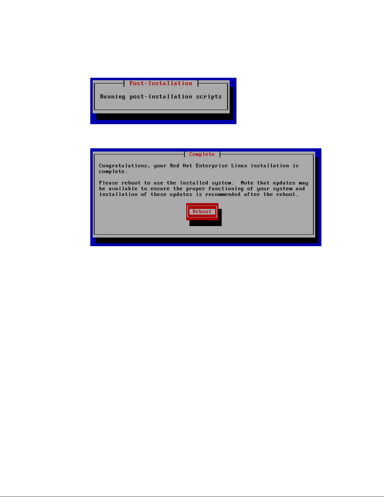
MCS 2.4 Installation and Configuration Guide
6. The RHEL installation proceeds.
When you see the “Post-Installation” message, it indicates the MCS installation scripts
are being executed.
7. When the installation process is complete, you are prompted to reboot. DO NOT
REBOOT before removing the MCS Installation USB drive.
If you reboot without removing the USB drive the server will reboot from the USB drive
again and re-launch the installer.
Note: If you pressed Enter by mistake, remove the USB drive as quickly as possible
(before the system boots up again). If this is not possible, you need to perform the
installation again.
8. Once the MCS Installation USB drive is removed, press Enter to reboot the server.
62
Page 63
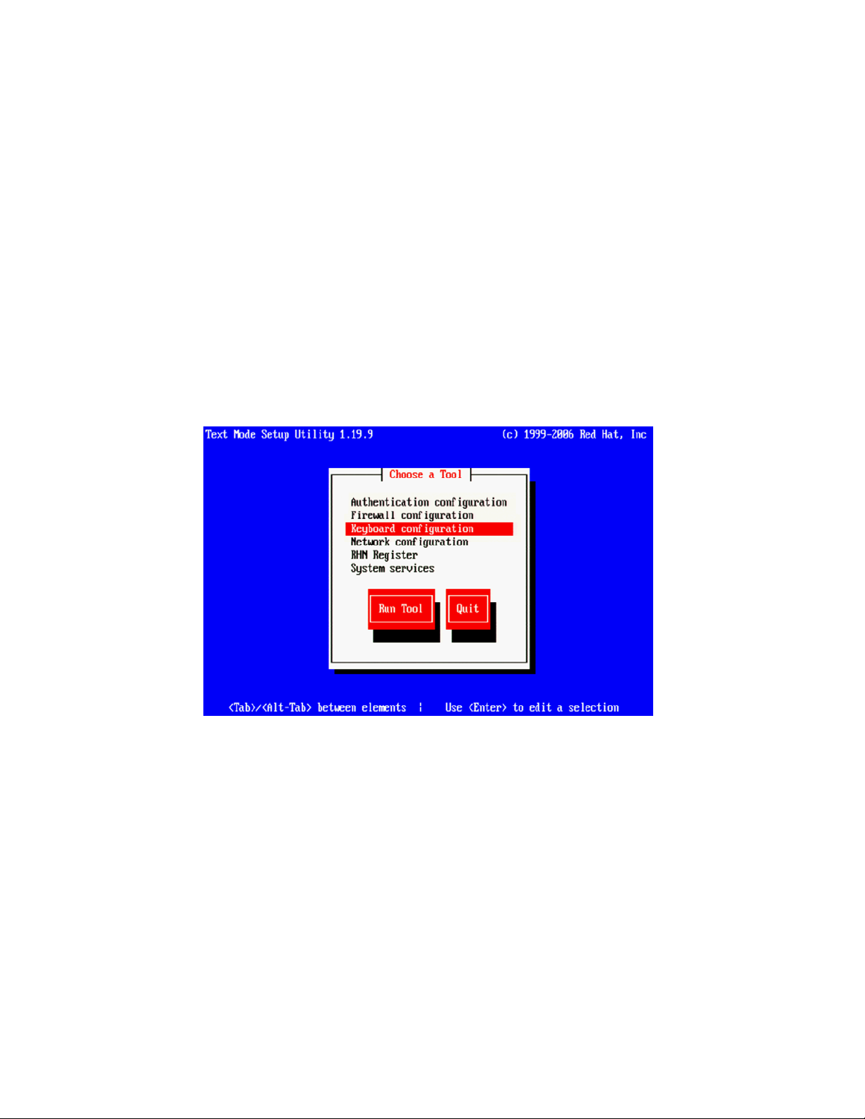
MCS 2.4 Installation and Configuration Guide
Booting RHEL for the First Time
Booting from the System Drive
Like many operating systems, when you boot RHEL for the first time, you will be asked to
provide some basic information. A RHEL “first boot” causes the RHEL Configuration screen to
appear, providing access to system set-up menus.
Note: The first boot set-up menu can be accessed at any time by typing “setup” (without
quotes) at the Linux command prompt.
Note: Some MCS software components depend on the language for RHEL being set to
English. This is done automatically by the MCS installation scripts. Do not change the
input language afterwards.
1. From the Choose a Tool menu, arrow down to select “Keyboard Configuration” and
press Enter.
2. In the Keyboard Selection menu, use the arrows to select the appropriate language for
your keyboard.
Note: Selecting a language for the keyboard is different from the language selected for
RHEL. While selecting a different language for the keyboard is supported, the RHEL
language must remain as English.
3. Press the Tab key to focus on the OK button and press Enter.
4. Press the Tab key to focus on the Quit button and press Enter.
The first boot set-up menu can be accessed at any time by typing “setup” (without quotes) at
the Linux command prompt.
63
Page 64

MCS 2.4 Installation and Configuration Guide
Changing the
root
Password
The RHEL installation script configures a default password for the root user (the Linux user with
administrator privileges). For security reasons, it is strongly suggested that you change the
password for the root user at the earliest opportunity.
To change the root password:
1. Log in a the Linux prompt
Default user name: root
Default password: Avid123
2. While logged in as the root user type the Linux change password command:
passwd
3. Follow the prompts to change the password.
If you do not enter a strong password, RedHat will warn you that the password is bad.
This could be because you have entered a password based on a word in the dictionary.
While this warning can be ignored, Avid suggests using strong passwords.
64
Page 65

MCS 2.4 Installation and Configuration Guide
Network Configuration
Verify DNS
MCS servers support both static and dynamic (DHCP) IP addressing. Static addressing is the Avid
recommended method for any MCS server and is a requirement for any MCS cluster
deployment.
Normally, on a server with multiple network interfaces (i.e. Ethernet connectors), each interface
has its own IP address. However, MCS servers in Interplay MAM can benefit from port bonding
(a.k.a. teaming), in which several network interfaces appear as a single IP address. Port bonding
is supported in MCS for MAM deployments only. For more information, see
Configuring Port Bonding for Interplay MAM.
Under the Linux operating system, every physical network connector, called an interface in
Linux, has a name. By default, when installing RHEL, the installer scans the NIC cards in the
machine and labels the interfaces it finds, in the order it finds them.
HP Servers: Each interface in an HP server is labeled “ethx”, where ‘x’ is an incremental
number starting with zero. Example: eth0, eth1, eth2 and so on. This naming convention is
true for both onboard and add-in (PCIe) network adapters.
Dell Onboard: The Dell onboard interfaces are similar to the HP in that each interface is
labeled as “emx”, where ‘x’ is an incremental number starting with one. Example: em1,
em2, em3 and so on. This naming convention only applies to the onboard 1 Gb interfaces.
Appendix B:
Dell PCIe Slots: The PCIe slots in a Dell are labeled as “p1p1” (slot 1) and “p2p1” (slot 2). If
you are using a 10 Gb network adapter in the Dell, it will be assigned one of these labels;
depending upon where you added the card (either slot is acceptable).
Note: This installation guide will use “eth0 as the default example for many commands. If
you are using a Dell server, make sure to substitute “eth0”with the correct interface name
for your deployment. In general on a Dell, these should be “em1” or “p1p1”.
Note: To obtain a list of the NICs installed in your system, enter the following in a Linux
command prompt: lspci | grep net
The Avid MCS implementation on RHEL is not configured to automatically register in DNS. Work
with your onsite IT Department to manually enter each MCS server in both Forward and Reverse
DNS.
If you will be configuring an MCS cluster, the cluster’s virtual IP and hostname should also be
entered in DNS.
From a Windows system, the “nslookup” command can be used in a command prompt to check
the DNS records directly.
65
Page 66

MCS 2.4 Installation and Configuration Guide
Identifying NIC Interfaces and Connecting the Network Cable
RHEL provides a simple means for visually identifying the NIC ports on a server, whether they
are active or not. The ethtool command can be used to cause ports to blink for a pre-determined
amount of time.
To visually identify a NIC Interface:
1. Use the Linux ethtool command, identify your primary network interface by causing it to
blink for 60 seconds:
ethtool --identify <interface name> 60
Where <interface name> is the name of the interface you want to identify.
• For HP servers, this is: eth0
• For Dell servers using a 1 Gb connection, this is: em1
• For Dell servers using a 10 Gb connection, this is: p1p1 or p2p1
Example:
ethtool -–identify eth0 60
Note the use of the double-dash in the identify command. In Linux, a single- or doubledash distinguishes options from arguments. A double-dash often precedes a word (i.e.
human readable) option.
2. Connect your network cable at this time.
a. If you are on a Dell server, connect your network cable to the interface that
flashed for “em1”, “p1p1” or “p2p1”.
Skip to Ensuring the NIC Interface Comes Up at System Startup on page 74
b. If you are on an HP server and will be connecting through a 1 Gb connection to a
supported onboard NIC, connect your network cable to the interface that
flashed for “eth0”.
Skip to Ensuring the NIC Interface Comes Up at System Startup on page 74
c. If you are on an HP server and will be connecting through 10 Gb connection,
connect the fibre cable to the PCIe card.
Proceed to (HP Only) Verifying the NIC Interface Name on page 67
.
d. If you are on an HP server and will be connecting through a 1 Gb connection to
an add-in 1 Gb NIC, “eth0” may or may not have flashed on that card. If the
above command made “eth0” flash on the add-in card, connect your cable to
the port that flashed. If the above command made “eth0” flash on the onboard
adapter, connect the network cable to the first port (far left) of the add-in card
and repeat the identify command to determine the name of the port you are
connected to (you will need this information in the following step).
.
.
Proceed to (HP Only) Verifying the NIC Interface Name on page 67
.
3. If needed, repeat the above to identify additional ports.
66
Page 67

MCS 2.4 Installation and Configuration Guide
(HP Only) Verifying the NIC Interface Name
(HP Only) Swapping NIC Interface Names
In an HP server, Avid assumes that interface “eth0” will be used. Since all interfaces in an HP
server are named “ethx”, additional steps need to be taken to ensure “eth0” is used.
To verify the NIC interface name:
1. Enter the RHEL Configuration screens by typing the following at the command prompt:
setup
2. From the Choose a Tool menu, select Network Configuration. Press Enter.
3. From the Network Configuration menu, select Device Configuration. Press Enter.
A list of NIC cards contained in the server enclosure appears.
4. Make note of the name associated with your interface. If necessary, use the arrow keys
to move up and down the list.
In the above example, a 10 Gb card has been placed in the server. It is currently
assigned “eth4”, but we will want to change that to “eth0”.
5. Note the name assigned to the interface of interest (e.g. eth0, eth1, ethn).
6. Perform the actions required at each menu (Cancel, Quit, Exit, etc.) to return to the
Linux prompt.
If your interface of interest was not already named “eth0”, you will need to rename it. You will
also rename the NIC interface currently using the name “eth0”.
1. Edit the network script where persistent names are assigned to network interfaces:
vi /etc/udev/rules.d/70-persistent-net.rules
Note: A server with just one installed NIC card does not have a 70-persistent-net.rules file by
default. If the file is missing for any reason, it can be created using the following command:
udevadm trigger --subsystem-match=net
The output may look similar to the following. Note that in the example below, the 10Gb
Myricom card has been assigned “eth4”. In this scenario, you will want to swap the
names for “eth0” and “eth4” so that the desired Myricom board is renamed “eth0”.
67
Page 68

MCS 2.4 Installation and Configuration Guide
# PCI device 0x14e4:0x1657 (tg3)
SUBSYSTEM=="net", ACTION=="add", DRIVERS=="?*",
ATTR{address}=="ac:16:2d:74:1b:58", ATTR{type}=="1", KERNEL=="eth*",
NAME="eth0"
# PCI device 0x14e4:0x1657 (tg3)
SUBSYSTEM=="net", ACTION=="add", DRIVERS=="?*",
ATTR{address}=="ac:16:2d:74:1b:59", ATTR{type}=="1", KERNEL=="eth*",
NAME="eth1"
# PCI device 0x14e4:0x1657 (tg3)
SUBSYSTEM=="net", ACTION=="add", DRIVERS=="?*",
ATTR{address}=="ac:16:2d:74:1b:5a", ATTR{type}=="1", KERNEL=="eth*",
NAME="eth2"
# PCI device 0x14e4:0x1657 (tg3)
SUBSYSTEM=="net", ACTION=="add", DRIVERS=="?*",
ATTR{address}=="ac:16:2d:74:1b:5b", ATTR{type}=="1", KERNEL=="eth*",
NAME="eth3"
# PCI device 0x14c1:0x0008 (myri10ge)
SUBSYSTEM=="net", ACTION=="add", DRIVERS=="?*",
ATTR{address}=="00:60:dd:45:14:50", ATTR{type}=="1", KERNEL=="eth*",
NAME="eth4"
2. Locate the lines corresponding to the NIC card you want to name eth0 and the one
already using the name.
Use the arrow keys on the keyboard to navigate the file.
3. Press the A key to append to the end of the line:
NAME="eth0"
4. Change NAME="ethX" (e.g. eth1, eth2, etc.) to the following:
NAME="eth0"
5. Locate the line corresponding to the NIC card that was already using the name eth0 and
rename it:
NAME="ethX"
where “X” is the number you removed in step 5 (e.g. eth1, eth2, etc.); that is, swap the
names.
6. Save and exit the vi session. Press <ESC> and type:
:wq
68
Page 69

MCS 2.4 Installation and Configuration Guide
(HP Only) Removing the MAC Address Hardware References
In addition to renaming the NIC interface, you will also need to remove the hardware references
– generally known as MAC addresses – from the affected NIC interface configuration files.
For each card where you renamed a NIC interface, edit the corresponding interface
configuration file and remove the hardware identifier. Otherwise, Linux will override the
changes you made earlier and reassign the old interface names the next time it boots (or you
restart the Linux network services).
1. Using the Linux text editor, vi, open the interface configuration file for one of the
renamed interfaces (e.g. ifcfg-eth0):
vi /etc/sysconfig/network-scripts/ifcfg-eth0
In Linux, each NIC interface has its own configuration file.
2. Locate the line containing the hardware identifier. It has the following form:
HWADDR = 00:00:00:00:00:00
3. Position the cursor on the HWADDR line and press “dd” to remove it. That is tap the
lower case letter D twice.
4. Save and exit the vi session. Press <ESC> and type:
:wq
5. Repeat the above steps for the other NIC interface you renamed (e.g. ethX).
6. Once you have finished removing the hardware references for both the renamed NIC
interfaces, reboot the server to restart the network services and make the effects
permanent:
reboot
The MAC addresses will refresh automatically after the reboot.
7. Once the system has rebooted, log back into RHEL.
Note: Changing the contents of the /etc/udev/rules.d file requires a reboot rather than
simply restarting network service.
69
Page 70

MCS 2.4 Installation and Configuration Guide
Configuring the Hostname and Static Network Route
This process will assume the configuration of a static IP address is desired.
1. Enter the RHEL Configuration screens by typing the following at the command prompt:
setup
2. From the Choose a Tool menu, select Network Configuration. Press Enter.
3. From the Network Configuration menu, select Device Configuration. Press Enter.
A list of NIC cards contained in the server enclosure appears.
4. Use the arrow keys to locate the primary interface (eth0, em1 or p1p1). Press Enter to
view its details.
Note: If you configured port bonding for an Interplay MAM integration, your primary
interface may be called “bond0”. For more information on port bonding, see Appendix B.
5. Dynamic Host Configuration Protocol (DHCP) is the default option. Arrow down to the
“Use DHCP” line and press the spacebar to deselect it.
6. Enter the following information:
Static IP address
Netmask (Subnet)
Note: All MCS servers in a cluster must be in the same subnet.
Default gateway IP
Primary DNS server
Secondary DNS server (if applicable)
70
Page 71

MCS 2.4 Installation and Configuration Guide
7. Arrow or Tab down to the OK button and press Enter.
You are returned to the list of NIC cards in the enclosure.
8. Select Save and press Enter.
9. From the Choose a Tool menu, select DNS Configuration. Press Enter.
10. Enter the following information for the DNS Configuration:
Enter the hostname
This should be entered as the short hostname only (e.g. wavd-mcs01) and not the
fully qualified domain name (FQDN) (e.g. wavd-mcs01-wavd.com).
Note: Hostnames should comply with “RFC 952” standards. Hostnames can be up to
24 characters, but Avid recommends keeping it under 15 characters. Hostnames
can contain numbers, but never begin a hostname with a number. The only “special
character” allowed in a hostname is a dash “ - “. Underscores are not allowed.
Primary DNS server
Secondary DNS server (if applicable)
Tertiary DNS server (if applicable)
DNS search path
11. Select Save & Quit. Press Enter.
12. Select Quit. Press Enter.
71
Page 72

MCS 2.4 Installation and Configuration Guide
Verifying the
hosts
File Contents
The hosts file is used by the operating system to map hostnames to IP addresses. It allows
network transactions on the computer to resolve the right targets on the network when the
instructions carry a “people-friendly” hostname (e.g. wavd-mcs01) rather than an IP address
(e.g. 192.XXX.XXX.XXX). Querying and waiting for a response from a DNS server can be slow due
to network latency. The hosts file assists in quickly resolving hostnames to IPs which is
particularly important for clustered configurations.
By default the hosts file on a computer resolves the machine’s own IP address to localhost. In
this step, you verify the content of the hosts file, and remove any extra entries, if present. In
addition, since the active hosts file can be reset to its default configuration when a server fails or
is rebooted you also verify the system default hosts file.
1. Using the following command, open the active hosts (/etc/hosts) file for editing:
vi /etc/hosts
It should look similar to the following:
127.0.0.1 localhost localhost.localdomain localhost4 localhost4.localdomain4
::1 localhost localhost.localdomain localhost6 localhost6.localdomain6
In this example, the default IP address of 127.0.0.1 is mapped to various forms of
localhost, for both ipv4 and ipv6 systems.
In some cases, the entries include an explicit call-out of the computer’s own host name
(e.g. wavd-mcs01):
127.0.0.1 localhost localhost.localdomain localhost4 localhost4.localdomain4 wavd-mcs01
::1 localhost localhost.localdomain localhost6 localhost6.localdomain6 wavd-mcs01
Note: In a cluster the explicit call-out of the computer’s own host name is particularly
problematic. If this entry remains unaltered, another node querying "wavd-mcs01" for its IP
address would receive "127.0.0.1" in response. The querying node would send messages to
itself instead of to the real "wavd-mcs01", and clustering would not function normally.
2. If the computer’s own host name is present (e.g. wavd-mcs01), remove it:
127.0.0.1 localhost localhost.localdomain localhost4 localhost4.localdomain4
::1 localhost localhost.localdomain localhost6 localhost6.localdomain6
3. If you will be configuring an MCS cluster, you will want to add the IP addresses, FQDN
and hostnames of each of the cluster nodes and the virtual cluster.
For a four node cluster, for example, you would add five lines similar to the following:
127.0.0.1 localhost localhost.localdomain localhost4 localhost4.localdomain4
::1 localhost localhost.localdomain localhost6 localhost6.localdomain6
192.168.10.50 wavd-mcs.wavd.com wavd-mcs
192.168.10.51 wavd-mcs01.wavd.com wavd-mcs01
192.168.10.52 wavd-mcs02.wavd.com wavd-mcs02
192.168.10.53 wavd-mcs03.wavd.com wavd-mcs03
192.168.10.54 wavd-mcs04.wavd.com wavd-mcs04
72
Page 73

MCS 2.4 Installation and Configuration Guide
Verifying the Contents of resolv.conf and nsswitch.conf
Note: It is a good idea to declare the nodes in the hosts file in order of latency, ascending.
Run a ping command to each node and add the lines to the file in order of the ping return.
For example, if node-2 returns a ping after 30ms and node-3 after 20ms, put in the line for
node-3 before node-2.
4. Save and exit the vi session. Press <ESC> and type:
:wq
5. If you made changes, verify that the system default hosts file reflects the changes.
cat /etc/sysconfig/networking/profiles/default/hosts
If necessary, “vi” can be used to edit the file to match the changes you made to toe
master hosts file.
Verifying the resolv.conf file:
The resolv.conf file contains your DNS and domain information.
1. Verify the DNS Server information has been stored in the RHEL resolver configuration
(resolv.conf) file:
cat /etc/resolv.conf
The DNS servers and DNS search path should be present in the file.
Using the vi editor, one or more additional search domains can be entered if necessary.
The search list is limited to six domains with a total of 256 characters. The file should
look something like:
nameserver <IP address of server1> (Primary DNS server)
nameserver <IP address of server2> (Secondary DNS server)
search domain1.com domain2.com (multiple domain names separated by a
single space or tab can be entered)
2. Delete any backup resolver configuration (resolv.conf.save) file that might have been
automatically created by the OS:
rm /etc/resolv.conf.save
Note: Due to a caveat in Linux, if you do not delete the resolv.conf.save file, when you
reboot, Linux overwrites the changes you just made.
Verifying the nsswitch.conf file:
Avid adjusts the nsswitch.conf file to instruct RHEL to prefer the local hosts file over DNS. In
cluster configurations, this ensures that there is no latency when attempting to discover the
cluster nodes.
1. Type:
cat /etc/nsswitch.conf | grep hosts
73
Page 74

MCS 2.4 Installation and Configuration Guide
Ensuring the NIC Interface Comes Up at System Startup
The system outputs the lines containing the string “hosts”, similar to the following:
#hosts: db files nisplus nis dns
hosts: files dns
In the second line, ensure the word “files” comes before the word “dns”.
2. If “files” does not appear before “dns”, use the vi editor to reverse the priority order.
In this step you verify that the primary network interface is set to come up when the system
boots.
1. Using the Linux text editor, vi, open the interface configuration file for eth0 for editing:
vi /etc/sysconfig/network-scripts/ifcfg-eth0
Note: If you are on a Dell server, remember to substitute “em1”, “p1p1” for “eth0”.
2. When you open the file for editing, it should look something like this:
DEVICE=eth0
HWADDR=00:60:dd:45:15:11
TYPE=Ethernet
UUID=
ONBOOT=yes
NM_CONTROLLED=no
DHCP_HOSTNAME=’$HOSTNAME’
BOOTPROTO=none
IPADDR=192.169.10.51
NETMASK=255.255.255.0
DNS1=192.169.10.10
DNS2=192.169.10.20
GATEWAY=192.168.10.1
USERCTL=no
IPV6INIT=no
3. Ensure that the ONBOOT entry is set to “yes”. If it is not, the interface will not be active
after rebooting the server.
4. Save and exit the vi session. Press <ESC> and type:
:wq
5. Reboot the MCS server:
reboot
Note: You are asked to reboot at this time to ensure that all networking changes are
active and the system comes up as expected. If you do not reboot, some of the steps in
the next procedure will fail.
6. Once the system has rebooted, log back into RHEL.
74
Page 75

MCS 2.4 Installation and Configuration Guide
Verifying Hostname, Network and DNS Connectivity
Before continuing, take a moment to verify that the server’s hostname responds as expected
and that network connectivity is now established.
To verify the hostname:
1. Verify the short hostname. In the RHEL command prompt, type:
hostname
The short hostname (e.g. wavd-mcs01) should be print to the screen.
2. Verify the fully qualified domain name (FQDN). In the RHEL command prompt, type:
hostname -f
The fully qualified hostname (e.g. wavd-mcs01.wavd.com) should be print to the screen.
If you do not receive the expected output, verify your hosts file and the resolv.conf file.
To verify network connectivity:
1. Use the ping command to verify connectivity to your network gateway address.
ping –c 4 <Gateway IP address>
“ping” is the command. “-c 4” is the count of how many times the ping command is
issued. If you do not specify a count, ping will continue forever. In that event, press
CTRL-C to stop the ping. Example:
[root@wavd-mcs01 ~]# ping -c 4 192.168.10.1
PING 192.168.10.1 (192.168.10.1) 56(84) bytes of data.
64 bytes from 192.168.10.1: icmp_seq=1 ttl=255 time=0.362 ms
64 bytes from 192.168.10.1: icmp_seq=2 ttl=255 time=0.330 ms
64 bytes from 192.168.10.1: icmp_seq=3 ttl=255 time=0.302 ms
64 bytes from 192.168.10.1: icmp_seq=4 ttl=255 time=0.804 ms
2. Now use the ping command to test the connection to host servers in your network.
Examples of host servers could be: Interplay Production Engines, ISIS servers, iNEWS
servers, etc. This will not only test connection to the host server, but also verifies DNS.
ping –c 4 <hostname>
3. Verify the same test, this time by pinging the host servers by IP address.
Note: Now that you have configured and verified the connection to the network, you can now
switch to using an indirect method for configuring the server. For more information refer back to
Accessing the MCS Server(s) on page 15.
75
Page 76

MCS 2.4 Installation and Configuration Guide
Configure Date and Time Settings
Setting the Time Zone
Ensuring that the date, time and time zone are correct on each MCS server is critical to a
successful implementation. This process will walk you through configuring the above values as
well as setting a Network Time Protocol (NTP) source for continued time synchronization.
If you do not have an NTP server already configured, see your local IT Department about
creating one prior to continuing with this process. Maintaining time synchronization between
MCS servers and host systems (ISIS, Interplay Production, etc) is critical. Maintaining time
synchronization between nodes in an MCS cluster configuration is particularly critical.
1. The installation script sets the default location to “America/New_York”. Verify this by
viewing the contents of the Linux “clock” file.
cat /etc/sysconfig/clock
If the US/Eastern time zone is appropriate for your installation, skip this process.
Otherwise, continue…
2. List the contents of the directory containing RHEL time zone information:
ls /usr/share/zoneinfo
A list of time zone regions is presented. For example:
US time zones are located in: /usr/share/zoneinfo/US (standard US time zones)
European time zones are located in: /usr/share/zoneinfo/Europe
And so on...
3. List the contents of the directory that are specific to your location. Example:
ls /usr/share/zoneinfo/US
4. Make note of the time zone name that relates to your installation.
5. Edit the clock file to reflect the correct time zone for your installation.
vi /etc/sysconfig/clock
Example: Replace zone="America/New_York" with zone="US/Pacific"
6. Save and exit the vi session. Press <ESC> and type: :wq
7. Create the symbolic link RHEL needs to make use of the new time zone information:
ln –sf /usr/share/zoneinfo/<yourzone> /etc/localtime
In the above command, <yourzone> is the path you entered in the clock file (e.g.
US/Pacific).
76
Page 77

MCS 2.4 Installation and Configuration Guide
Synching the System Clock
Note: Creating a symbolic link is more robust than copying. For example, the files in
/usr/share/zoneinfo contain daylight saving time (DST) information. A symbolic link allows
your system to automatically accommodate changes to DST practices that might arise in the
future. Such changes would be propagated through RHEL updates to the /usr/share/zoneinfo
files.
8. Verify the settings using the date command:
date
The local time and time zone should now be shown.
In this step you set the Network Time Protocol (NTP) daemon to automatically synchronize the
system clock with an NTP time server every 30 minutes. This is done by creating a job for the
Linux cron utility. The cron job runs the NTP daemon, ntpd.
Note: Setting up ntpd to run as a service at startup is also a possibility. However, some
consider it a security risk to run ntpd in “continuous” mode. The technique shown here
keeps the system clock synchronized while minimizing exposure to risk by causing ntpd
to exit after it fetches the correct time.
Note: The use of the iburst option within the cron job is not recommended. It produces
very rapid time shifts and can lead to synchronization problems.
1. Verify the current date and time with the date command. Type: date
2. This process will verify connectivity to the NTP server. Change the date and time so that the
clock is 10 minutes behind the correct time of day.
date MMDDHHmmYYYY
Note: If you set the clock more than 1000ms (~17min) off from your NTP server, the time
may not update.
3. Check the status of the ntpd service. Type:
If the service is running, stop the service. Type:
service ntpd status
service ntpd stop
4. Verify that the NTP server of interest is reachable by querying it:
ntpdate -q <ntp_server_address>
Example output:
server 192.168.10.25, stratum 3, offset 468.746036, delay 0.02585
1 Jan 13:05:00 ntpdate[7554]: step time server 192.168.10.25 offset
468.746036 sec
5. Edit the NTP configuration (ntp.conf) file:
vi /etc/ntp.conf
77
Page 78

MCS 2.4 Installation and Configuration Guide
6. Scroll down to the section of the file that details the NTP servers and place a ‘#’ symbol in
front of any existing NTP servers to comment them out. For example:
# server 0.rhel.pool.ntp.org
# server 1.rhel.pool.ntp.org
# server 2.rhel.pool.ntp.org
7. Update the file with the NTP information for your configuration. Updated example:
# server 0.rhel.pool.ntp.org
# server 1.rhel.pool.ntp.org
# server 2.rhel.pool.ntp.org
server 192.168.10.25
server 192.168.10.26
Save and exit the vi session. Press <ESC> and type: :wq
8.
9. Set up a cron job by creating a new file containing instructions for cron:
vi /etc/cron.d/ntpd
10. Add a line with the instructions for cron:
0,30 * * * * root /usr/sbin/ntpd -q -u ntp:ntp
The command above instructs cron to:
• Run the cron job every 30 minutes as root.
“0,30” is a comma-separated list (i.e. run at 0 minutes and 30 minutes). “*” is a
special list indicating every value in the list (i.e. every hour, every day of the month,
every month, every day of week).
• The job is /usr/sbin/ntpd
• The -q switch tells ntpd to exit after it sets the system clock
• The -u switch tells Linux to run the job as user ntp, in user group ntp
The general form of the cron command is the following:
# Minute Hour Day of Month Month Day of Week
# (0-59) (0-23) (1-31) (1-12 or Jan-Dec) (0-6 or Sun-Sat)
11. Save and exit the vi session. Press <ESC> and type: :wq
12. Once again, verify the current date and time. It should be 10 minutes behind the correct
clock.
date
13. Update the system clock now by querying the NTP server with the NTP daemon:
/usr/sbin/ntpd -q -u ntp:ntp
The system responds with a message similar to the following:
ntpd: time set +570.677029s
14. Verify the updated date and time:
date
78
Page 79

MCS 2.4 Installation and Configuration Guide
Creating the File Cache on the RAID
Partitioning the RAID
If your configuration does not include a RAID 5, continue to one of the following (as appropriate
for your installation):
• Configuring MCS for MediaCentral UX and Media Composer Cloud
• Configuring MCS for Interplay MAM
In an earlier step you might have created a RAID 5 for the cache using the “arrays” utility built-in
to the server’s BIOS. In this step you will partition the RAID, create a logical volume for the RAID
and mount the MCS cache on it.
In this procedure you partition the RAID and write the new partition table entry to disk using the
GNU parted disk partitioning utility.
The enclosure contains two devices of interest, the system disk (/dev/sda) and the RAID
(/dev/sdb). Partitioning the system disk was performed automatically by the RHEL installer. You
only need to partition the RAID, as indicated in this section.
Note: Starting with RHEL 6.3, Red Hat creates a GPT volume when the MCS installation
scripts initialize the cache volume during OS installation. GPT volumes must be handled
using the GNU parted utility (rather than the Linux fdisk utility).
To partition the RAID:
1. Use the GNU parted utility to ensure the RAID 5 HD device exists:
parted –l
Note: Note the command take a lower-case “L” (not a numerical “one”).
Note: The Linux “fdisk -l” command can also be used to list the devices. However, it
returns the following warning:
WARNING: GPT (GUID Partition Table) detected on '/dev/sdb'! The
util fdisk doesn't support GPT. Use GNU Parted.
2. Find the free space on the /dev/sdb device:
parted /dev/sdb p free
Information similar to the following is displayed:
Model: HP LOGICAL VOLUME (scsi)
Disk /dev/sdb: 2500GB
Sector size (logical/physical): 512B/512B
Partition Table: gpt
Number Start End Size File system Name Flags
17.4kB 2500GB 2500GB Free Space
79
Page 80

MCS 2.4 Installation and Configuration Guide
Creating the Logical Volume, Filesystem and Mounting the Cache
3. Create a primary partition on the RAID 5 using all the available space (2500 GB in the
sample output provided above):
parted -a optimal /dev/sdb mkpart primary ext2 0% 2500GB
The system might respond with the following message:
Information: You may need to update /etc/fstab
The message can be ignored. You will update fstab when you create the logical volume
and mount the cache for the new partition.
4. Set sdb partition one to type logical volume, and its state to on.
parted /dev/sdb set 1 lvm on
5. Run the parted utility again to list your changes:
parted -l
Model: HP LOGICAL VOLUME (scsi)
Disk /dev/sdb: 2500GB
Sector size (logical/physical): 512B/512B
Partition Table: gpt
Number Start End Size File system Name Flags
1 17.4kB 2500GB 2500GB primary lvm
Notice in the above output the partition now has a partition number, is the primary
partition, and has a logical volume flag. You create the filesystem in the next step.
In this procedure you work with the newly partitioned RAID 5 using the Linux Logical Volume
Manager (LVM). The hierarchy of volumes in Linux is as follows: physical volume, volume group
and logical volume.
To create the logical volume and mount the cache:
1. Create the physical volume:
pvcreate --metadatasize=64k /dev/sdb1
Note the name of the physical volume (/dev/sdb1) takes a 1 (one).
LVM feedback indicates the successful creation of the physical volume.
2. Create a volume group, vg_ics_cache, containing the physical volume /dev/sdb1:
vgcreate -s 256k -M 2 vg_ics_cache /dev/sdb1
LVM feedback indicates the successful creation of the volume group.
80
Page 81

MCS 2.4 Installation and Configuration Guide
3. Before creating the logical volume, obtain a value for the volume group’s physical
extents:
vgdisplay vg_ics_cache
A list of properties for the volume groups appear, including the physical extents (Free
PE). Physical extents are the chunks of disk space that make up a logical volume.
Sample output is shown below:
--- Volume group -- VG Name vg_ics_cache
System ID
Format lvm2
Metadata Areas 1
Metadata Sequence No 2
VG Access read/write
VG Status resizable
MAX LV 0
Cur LV 1
Open LV 1
Max PV 0
Cur PV 1
Act PV 1
VG Size 1.09 TiB
PE Size 256.00 KiB
Total PE 4578332
Alloc PE / Size 0 / 0
Free PE / Size 4578332 / 1.09 TiB
VG UUID cyWpGZ-s3PG-8UqH-4TBl-rvBA-33oJ-3uZt0u
Use the “Free PE” value to create a logical volume occupying the entire volume group
(below).
4. Create the logical volume, lv_ics_cache, containing the volume group vg_ics_cache:
lvcreate -l <Free_PEs> -r 1024 -n lv_ics_cache vg_ics_cache
In the above command, replace <Free_PEs> with the value obtained in the previous
step. This is the number before the slash in the “Free PE” line. No unit is needed.
For example:
lvcreate -l 4578332 -r 1024 -n lv_ics_cache vg_ics_cache
Note the first switch in lvcreate is lower case “L”.
LVM feedback indicates the successful creation of the logical volume. Note that Linux
may override the sector size you specified. That is OK.
81
Page 82

MCS 2.4 Installation and Configuration Guide
5. Create a filesystem on the logical volume (i.e. format it):
mkfs.ext4 /dev/vg_ics_cache/lv_ics_cache
Note in the above command you specify logical volume by its Linux block device name
(/dev/<volume_group>/<logical_volume>).
As in other operating systems, formatting in RHEL is a slow operation. Please be patient.
Feedback similar to the following indicates success:
This filesystem will be automatically checked every 38 mounts or
180 days, whichever comes first. Use tune2fs -c or -i to override.
6. Edit the filesystem table:
vi /etc/fstab
7. Add an entry at the end of the file:
/dev/mapper/vg_ics_cache-lv_ics_cache /cache ext4 rw 0 0
This automates the mapping of the logical volume to a filesystem directory (/cache in
this case).
8. Save and exit the vi session. Press <ESC> and type:
:wq
9. Mount the volume:
mount /dev/mapper/vg_ics_cache-lv_ics_cache /cache
Alternately, since you added an entry to fstab, you ought to be able to mount the cache
as follows:
mount /cache
Note: If you receive an error indicating the mount point /cache does not exist, create the
cache manually and issue the mount command again:
mkdir /cache
mount /dev/mapper/vg_ics_cache-lv_ics_cache /cache
10. Verify that /cache has been mounted correctly:
df –h
The following information is displayed about the cache: size, used, available, user % and
mount point (mounted on), similar to the following:
Filesystem Size Used Avail Use% Mounted on
/dev/mapper/vg_ics_cache-lv_ics_cache
29G 585M 27G 3% /cache
11. Verify that /cache has the correct ownership and read-write-exec settings:
ls -la /cache
Information is displayed about the cache ownership, similar to the following:
drwxr-xr-x 5 maxmin maxmin 4096 Oct 16 10:02 .
82
Page 83

MCS 2.4 Installation and Configuration Guide
Enable / Disable 3G and Edge Streams
12. If the ownership is of /cache is not set to user maxmin, change its ownership:
chown maxmin:maxmin /cache
13. If the /cache directory does not have its read-write-exec settings are not rwx for owner,
group, other, change the permissions:
chmod 0777 /cache
14. Create the following two cache directories:
mkdir /cache/download
mkdir /cache/fl_cache
15. Change their ownership to user maxmin:
chown maxmin:maxmin /cache/download
chown maxmin:maxmin /cache/fl_cache
16. Change their permissions:
chmod -R 02777 /cache/download
chmod -R 02777 /cache/fl_cache
17. Verify that /cache and its subdirectories now have the correct ownership, read-write-
exec settings, and setgid special permission:
ls -la /cache
Updated information is displayed, which ought to be similar to the following:
drwxrwxrwx 5 maxmin maxmin 4096 Mar 22 10:04 .
Note: User maxmin owns the MCS process that writes to the cache. Avid processes will
create subdirectories in /cache, on an as-needed basis. If you are deploying a cluster, you will
revisit caching later in the installation to replicate the cluster contents using GlusterFS.
By default, MCS servers encode assets in three different media streams (Wi-Fi, 3G, and Edge) for
playback on mobile devices. If your facility intends to connect mobile devices through Wi-Fi
only, it is recommended that you disable the 3G and Edge streams, to improve the encoding
capacity of the MCS server. If your facility does not intend to connect any mobile devices to the
MediaCentral system, this file does not require editing. Mobile media formats are only created if
a device running the MediaCentral UX Mobile application connects and attempts to play media.
To Disable 3G and or Edge Streams:
1. Log in as root and edit the following file using a text editor (such as vi):
/usr/maxt/maxedit/share/MPEGPresets/MPEG2TS.mpegpreset
2. In each of the [Edge] and [3G] areas, set the active parameter to active=0.
3. Save and close the file.
To re-enable 3G or Edge, edit the file and reset the “active” value to 1.
83
Page 84

MCS 2.4 Installation and Configuration Guide
Copying Software to the MCS Server
Security Updates
Install Software Patches
Now that the basic RHEL installation is complete, you might need to copy additional software to
the MCS server. Common software includes:
RHEL Security Patches
MCS Software Updates
Closed Captioning Service installer
MAM Connector
For information on how to copy software to an MCS server, see
Server on page 177.
Once you have installed the operating system, please take a moment to resolve any outstanding
RHEL security vulnerabilities. For information and links to KB articles with instructions, see the
“Security Updates” section in the Avid MediaCentral Platform Services ReadMe.
Avid releases patches for MCS on a regular basis to assist in addressing customer issues and
feature requests. Refer to the Avid MediaCentral Platform Services ReadMe for information on
current patches and install any available patches at this time.
Copying Software to the MCS
84
Page 85

MCS 2.4 Installation and Configuration Guide
PART IV: CONFIGURING MCS
85
Page 86

MCS 2.4 Installation and Configuration Guide
Chapter Overview
Configuring MCS for MediaCentral UX and Media Composer Cloud
1
Updating the MediaCentral UX Configuration
2 min
Covers use of the Configurator Tool.
2
Logging into MediaCentral UX
5 min
Log in to MediaCentral for the first time.
3
Changing the Administrator Password
2 min
For security it is recommended you change the administrator password.
4
Creating a Second Administrator User
5 min
Helps to ensure you do not get locked out of the interface.
5
Configuring System Settings
varies
Covers the configuration of the MediaCentral System Settings.
6
Verifying the System Settings
varies
A process for testing the configured settings.
7
Configuring Send To Playback Settings
5 min
Configure settings for STP workflows.
8
Importing Domain Users
5 min
Covers the process of importing Windows Domain Users.
9
Creating Local Users and Assigning Roles
varies
Information on creating local users and role assignments.
10
Continuing the Installation
1 min
Suggestions for additional steps to continue your installation.
This chapter is divided into two main sections. Proceed to the section appropriate for your
installation:
- Configuring MCS for MediaCentral UX and Media Composer Cloud
o This section includes information on multiple workflows such as iNEWS, Interplay
Production, Media Composer Could, Send To Playback, etc. Read and apply the
sections appropriate for your installation.
- Configuring MCS for Interplay MAM
The following table describes the topics covered in this chapter.
Step Task Time Est.
86
Page 87

MCS 2.4 Installation and Configuration Guide
Configuring MCS for Interplay MAM
1 Configuring MCS for Interplay MAM
10 min
Configure MCS to mount the filesystems on which Interplay MAM
Step Task Time Est.
browse proxies reside.
Configure Interplay MAM to use the MCS server or server cluster
87
Page 88

MCS 2.4 Installation and Configuration Guide
Configuring MCS for MediaCentral UX and Media Composer Cloud
Updating the MediaCentral UX Configuration
MCPS
iNEWS
Interplay
Media
MediaCentral & Media
Standard MediaCentral
ON
ON
ON
OFF
Interplay Production Only
ON
OFF
ON
OFF
Now that you have installed and configured the operating system, you are ready to configure
the software and settings specific to MediaCentral.
As a reminder, if you are running a cluster, complete this section on the master node only
(unless instructed otherwise). Settings will be replicated to the other nodes during the cluster
configuration process.
By default, the MediaCentral UX user interface contains functionality for all the MCS solutions it
supports. Functions that are not required for your installation should be removed. If you are
configuring a cluster, this step only needs to be completed on the master and slave nodes, but it
is good practice to run the configurator on all nodes. This step can be completed on all nodes
concurrently.
1. Start the configurator by typing the following at the Linux prompt:
/opt/avid/avid-interplay-central/configurator
The configuration UI appears.
Note:
Media Distribute (not shown) appears in the Configurator UI only if it has been
installed on the system (through a separate installer).
2. Select the appropriate application profile settings.
The following table outlines typical settings by deployment type:
Settings
Production
Distribute
88
Distribute
ON ON ON ON
Page 89

MCS 2.4 Installation and Configuration Guide
MCPS
iNEWS
Interplay
Media
Media Composer Cloud
ON
OFF
ON
OFF
Interplay MAM
ON
OFF
OFF
OFF
iNEWS Only
OFF
ON
OFF
OFF
Logging into MediaCentral UX
Settings
Production
Distribute
For example, for an iNEWS-only deployment without video playback, you would enable
iNEWS and disable MCPS Settings and Interplay Production.
Note what each selection controls:
• MCPS Settings: Toggles the MCPS group in the System Settings layout. This
group provides access to the Load Balancer, Playback Services and Player
settings details pages.
• iNEWS: Toggles the iNEWS settings group.
• Interplay Production: Toggles the Interplay Production settings group.
• Media Distribute: Toggles the Interplay Media Distribute layout.
3. Use the Up and Down arrow keys to move between the options, Left and Right arrow
keys to move between OK and Cancel, SPACEBAR to toggle the asterisks, and press
Enter to confirm.
• Asterisk = enabled
• No Asterisk = disabled
Now when you access MediaCentral UX, the UI will be correctly configured for your
deployment.
MCS servers are configured using the MediaCentral UX System Settings. This process is
completed through the use of a web browser such as Google Chrome.
Note: If you are configuring a cluster, you configure the MediaCentral UX System
Settings once on the master node only. Do not configure these settings on slave or load
balancing nodes. The other nodes inherit settings from the master through the clustering
mechanisms. Complete all remaining sections of this chapter on the Master node only.
1. Launch a supported web browser or use the MediaCentral UX Desktop application to
access MediaCentral UX.
Supported browsers include: Google Chrome or Safari (on Mac OS).
2. Enter the URL of the MCS server in the address bar:
• https://<hostname> where <hostname> is the Fully Qualified Domain Name (FQDN),
the short host name, or the IP address of the MCS server.
89
Page 90
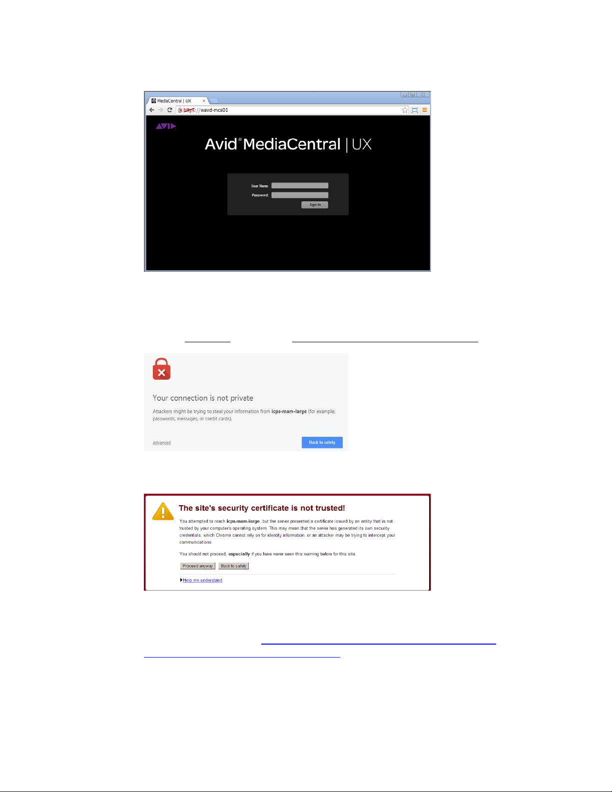
MCS 2.4 Installation and Configuration Guide
The MediaCentral UX sign-in screen appears.
In place of the sign-in screen, you might see a warning indicating the connection is not
private. The warning relates to SSL certificates.
For the purposes of installing and configuring MediaCentral UX, ignore the warning:
- Click Advanced and then the Proceed to <MediaCentral URL> (unsafe) link.
In older versions of Chrome (previous to release 37), the following warning is shown
instead:
In the above case, click Proceed Anyway.
Note: For information on configuring a trusted certificate, see the following article on
the Avid Knowledge Base:
Certificates-for-server-to-browser-connections.
http://avid.force.com/pkb/articles/en_US/how_to/SSL-
3. Enter the Administrator user and password to access MediaCentral UX:
• User name: Administrator
• Default Password: Avid123
90
Page 91

MCS 2.4 Installation and Configuration Guide
4. The first time any user signs in, the Avid Software License Agreement is presented. Click
the Accept License Agreement button to proceed.
5. Enter your account information. When you sign in to MediaCentral for the first time you
are prompted to enter your user credentials for iNEWS, Interplay Production, or both.
Sign in options depend on the features selected in the MediaCentral UX Configurator.
If you created custom iNEWS and Interplay Production credentials (e.g. MCSAdmin),
enter that information at this time. Otherwise, leave the defaults (Administrator /
Avid123).
Note: If the security settings for one of these systems is inaccurate, you will see a warning
message that states that the application is unable to authorize the sign-in name or
password. This will be the case for any iNEWS credentials entered, since you have not yet
specified the iNEWS server to be used. If you receive a warning, click the link provided and
verify your security settings.
6. Click the “Continue to MediaCentral UX” button.
7. If you are accessing MediaCentral UX through Chrome or Safari, you might be asked if
you want to “Send notifications”. This is related to the Desktop Notifications feature
introduced in MCS v2.4. Select either the Allow or Block option when presented with
this message.
If desired, this feature can be disabled. See Modifying application.properties
for
instructions.
See the Avid MediaCentral | UX User’s Guide for information on the Desktop
Notifications feature.
8. If you are using accessing MediaCentral UX through Chrome and you enabled iNEWS in
the MediaCentral Configurator tool, the first time you sign in to MediaCentral a dialog
box asks if you want to use MOS plug-ins.
91
Page 92

MCS 2.4 Installation and Configuration Guide
Changing the Administrator Password
Selecting “Yes” will enable the “MOS enabled” checkbox in the user settings and prompt
you to install the container needed for Active X controls.
Selecting “No” will not enable the MOS checkbox or prompt you to install any additional
software. The MOS checkbox can be enabled manually in the user’s settings at any
time.
MOS plug-ins require additional software as described in “
Active-X Plug-Ins” on page 232.
Note: Active X controls and MOS plug-ins are not supported in the Safari browser or in
Chrome v45 or higher.
For security reasons, it is strongly suggested that you change the password for the Administrator
1. While logged in as the Administrator, select Users from the Layout selector.
2. Expand the list of Administrators in the User Tree and locate the Administrator user.
Appendix F: Enabling MOS
3. Double-click on the Administrator account. Details will appear on the right.
4. Click the Change Password button in the Details pane, and enter a new password for the
Administrator user.
Note: MediaCentral v2.1 introduced strong password enforcement. This feature was made
optional in v2.2; however the default is to have strong passwords enabled. See the Avid
MediaCentral | UX Administration Guide for more information on this feature and a process
for “Turning Off Secure Password Requirements” if desired.
5. Click OK update the password information.
A message appears indicating that the password was successfully changed.
92
Page 93
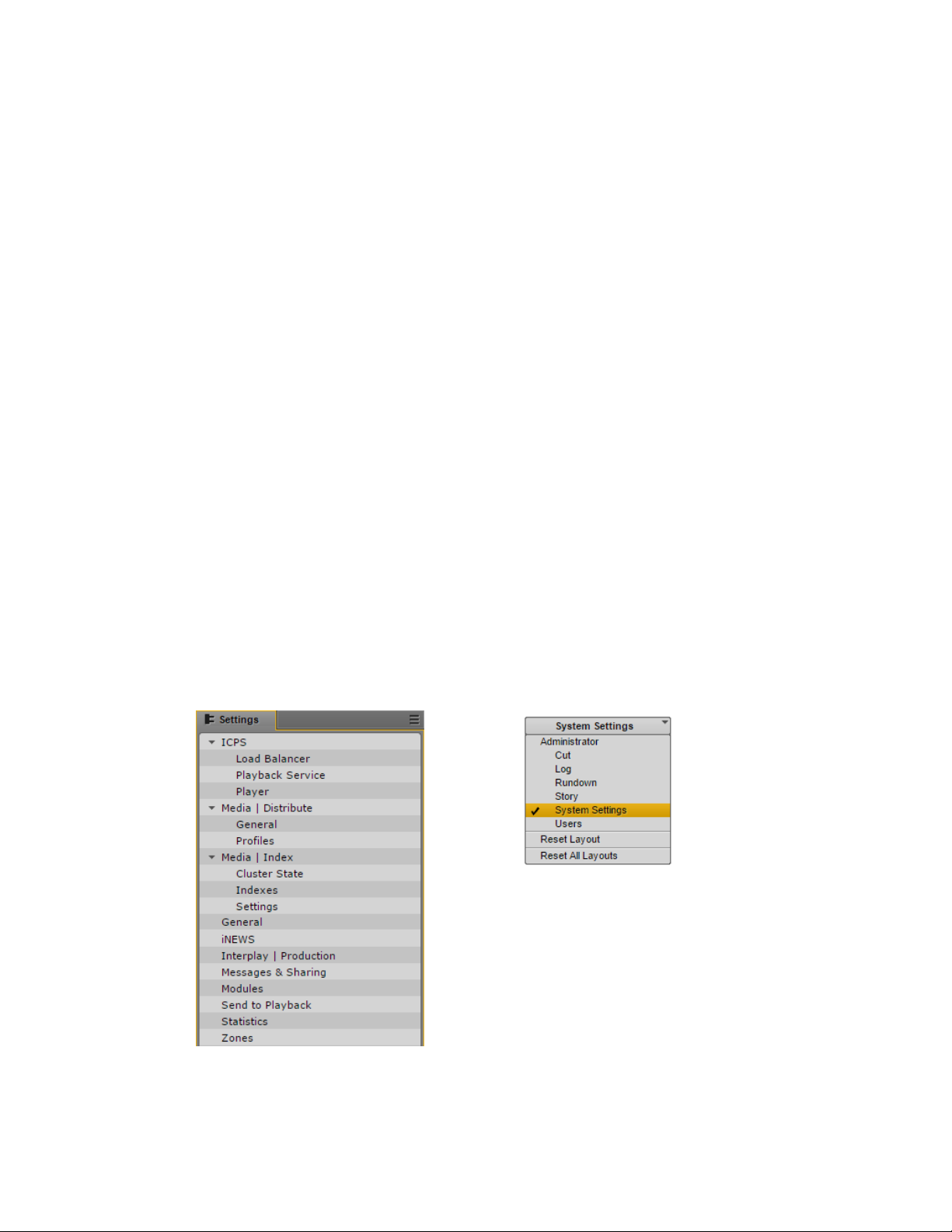
MCS 2.4 Installation and Configuration Guide
Creating a Second Administrator User
Configuring System Settings
In the event that you are locked out of MediaCentral for any reason, it is wise to create a second
Administrator-level user.
1. While in the Users Layout, highlight the Administrators group in the User Tree.
2. Click the Create User button under the User Tree tab.
3. In the Details pane, assign a User Name.
4. Enter a Password and confirm the password.
5. Deselect the checkbox for “User must change password at next sign-in.”
6. Click the Save button in the bottom-right corner of the window.
The user account is created.
Much of the configuration of MediaCentral is completed through the System Settings. Proceed
through the following sections and configure settings applicable to your configuration. For more
information, see the Avid MediaCentral | UX Administration Guide.
Note: If you are configuring a cluster, you configure the MediaCentral UX System Settings
once on the master node only. Do not configure these settings on slave or load balancing
nodes. The other nodes inherit settings from the master through the clustering mechanisms.
To access the System Settings, select “System Settings” from the Layout selector in the top-right
corner of the interface. This layout will only appear if you are logged in as a user with
Administrator rights.
Media Distribute settings are shown in the above example; however these settings will only
appear if Media Distribute has been installed on the system. For more information see the
Media Distribute Installation and Configuration Guide.
93
Page 94

MCS 2.4 Installation and Configuration Guide
General Settings
iNEWS Settings
This section configures general settings related to the overall operation of MediaCentral.
1. In the Settings pane, select General.
2. System ID: Every MCS system can be identified with a System ID provided by Avid at
point of sale. This ID can be used to access Avid Customer Care for systems with valid
support contracts.
Once entered, the System ID is stored in the ACS bus. The System ID is displayed when
you invoke the ics_version command from Linux or when you select Home>About within
the MediaCentral user interface.
Note: If you cannot locate your System ID, contact your Avid representative.
3. Search Pane:
value of this field is
Specify t he maximum number of assets to be displayed in a search. The default
50.
4. Session Timeout: Specify the number of minutes of inactivity before the user’s session
is disconnected. The range of this value is between 10 minutes and 1440 minutes (24
hours). The default value of this field is 30 minutes. As of MediaCentral v2.1.0, this
feature can be enabled or disabled.
5. Time Zone: Use the pull-down menu to select a default time zone for the local
MediaCentral system. This information is used to properly display assets when doing
searches outside of the local system. Examples:
- US/Eastern
- Europe/London
- Asia/Hong_Kong
6. Date Format: Use the pull-down menu to select a default date format for the local
MediaCentral system. This information is used to properly display assets when doing
searches outside of the local system. Options:
- DD.MM.YYYY hh:mm:ss
- DD/MM/YYYY hh:mm:ss
- YYYY-MM-DD hh:mm:ss
- MM/DD/YYYY hh:mm:ss
7. Click Apply to save your changes.
This section configures settings related to Avid iNEWS. ICS 1.0 – 1.4 supported connection to
only one iNEWS system. iNEWS Community support was added in ICS 1.5 with up to 24
members. ICS 1.8 increased possible community members to 50.
1. In the Settings pane, select iNEWS.
94
Page 95

MCS 2.4 Installation and Configuration Guide
Interplay Production Settings
2. System ID: Enter the System ID for your iNEWS system. This information can be found
on the iNEWS server(s) in the /site/system file. If your iNEWS system consists of
multiple servers for load balancing and failover, using the System ID ensures that
MediaCentral connects to iNEWS properly. iNEWS servers will often include a –a or –b
suffix in their hostname. Do not include these suffixes. Ensure that all MediaCentral
servers can resolve the hostnames and IP addresses of all iNEWS servers through DNS.
3. Timing: This value specifies how the iNEWS timing field is updated when you associate a
sequence with a story.
4. Tape ID: When you associate a sequence with a story, this iNEWS field name is
associated with the sequence’s Tape-ID field.
Example iNEWS field: video-id
5. Pagination: The maximum number of items listed in the Queue/Story pane or the
Project/Story pane. To view more items beyond the number displayed, click the Show
More Results button. The range is 5 to 255 items. The default value of this field is 50.
6. Click Apply to save your changes.
This section configures settings related to Interplay Production. Avid supports connecting
MediaCentral to only one Interplay Production system per MCS installation.
1. In the Settings pane, select Interplay | Production.
2. Interplay | Production Server: Enter the (short) hostname or virtual hostname of the
Interplay Production Engine. An IP address is also acceptable here. Do not use a Fully
Qualified Domain Name (FQDN) in this field.
3. MCDS Service URL: Enter the URL of the server or servers hosting the MediaCentral
Distribution Service. You can enter a hostname or IP address for the server. The
standard port number used by this service is 8443. If you have installed multiple copies
of MCDS, list each URL separated by a comma and a space. Multiple instances of MCDS
provide failover capability, but not load balancing.
Example: https://wavd-tc01:8443
4. Location for Script Sequence:
a. In the Path field, specify a folder in the Interplay Production database where
script sequences will be stored. The correct path format does not include a
leading slash.
Example: Projects/iNEWS or iNEWS/Scripts
b. Select whether you want sub-folders in the parent folder to be created by
Queue name, Date, or Story name.
5. Assets Pane: Sets the max number of Interplay assets to display at one time. This value
can range between 5 and 1000. The default value for this field is 50.
6. Click Apply to save your changes.
95
Page 96

MCS 2.4 Installation and Configuration Guide
Messages & Sharing
Playback Service Settings
These settings enable messages delivered through the messaging service to be forwarded to
user’s individual email accounts. These settings have nothing to do with emails sent from the
MCS cluster or other Linux processes. Only messages created in the Messaging Pane are
forwarded.
1. In the Settings pane, select Messages & Sharing.
2. Message Archiving: Configure the number of days to retain active messages. Messages
older than this will be archived. The default value of this field is 7.
Note: For instructions on retrieving archived messages, s
Administration Guide.
3. Email forwarding: If email forwarding is desired, enable the checkbox for this option.
Consult with your in-house IT Department for this information.
a. SMTP server hostname: Enter an SMTP server hostname.
Example: webmail.wavd.com
b. Port: Enter a communication port. The default port is 25.
c. User name: Enter a username in the form of an e-mail address.
Example: admin@wavd.com
d. Password: Enter the password for the associated user account.
e. Use SSL (Secure Sockets Layer): Select this checkbox if required by IT.
f. Ignore TLS (Transport Layer Security): Select this checkbox if required by IT.
4. Once you have configured the email forwarding fields, verify functionality by entering a
recipient email and clicking Validate.
Note: If the e-mail is not received, verify with your IT Department that ICMP traffic is
allowed through appropriate firewalls and network switches.
ee the Avid MediaCentral | UX
5. Click Apply to save your changes.
This section configures settings related to Interplay Central Playback Services (ICPS). ICPS is a set
of services that run on the MCS servers that are responsible for the compression and playback
of video and audio media.
1. In the Settings pane, select ICPS> Playback Service.
2. Player Settings: The “Save Failed AAF” feature automatically saves AAF files that do not
parse properly to a dedicated folder (/cache/aaf_to_investigate) on the MCS server.
This feature can assist in troubleshooting efforts and should only be enabled upon
request from Avid Customer Care.
96
Page 97

MCS 2.4 Installation and Configuration Guide
3. Interplay Workgroup Properties
a. User / Password: MediaCentral requires a dedicated user to access the
Interplay Production database. Enter that user and password.
Suggested User Name: MCSAdmin
b. Connect to HAG: Check this box to connect to an Interplay Production Media
Indexer High Availability Group (HAG). The HAG must already be configured in
Interplay Production.
MediaCentral connects to the primary node of the HAG only. It does not
Note:
participate in HAG redundancy.
c. MI Host: If you did not select the Connect to HAG checkbox, enter the (short)
hostname of the Interplay Media Indexer to connect to a specific Media Indexer.
An IP address can also be used in this field. Do not use a Fully Qualified Domain
Name (FQDN) in this field.
Note:
Checking the Connect to HAG box grays-out the MI Host field.
d. Workgroup Name: Enter the name of the Interplay Production Workgroup
(Framework). The Workgroup Name is case sensitive.
e. Lookup Servers: Enter the (short) hostname of the server hosting the Interplay
Production Framework Lookup Service. If there are multiple Lookup Servers,
enter each hostname separated by a comma. Do not use a Fully Qualified
Domain Name (FQDN) in this field.
f. Enable Dynamic Relink: If working in a multi-resolution environment,
environments with Interplay Capture or environments with Interplay Archive
using partial restore workflows, enable this checkbox.
4. General ISIS Settings
a. Enable Remote Host: If you are connected to Avid ISIS through a Zone1 or
Zone2 network connection, leave this box unchecked. If you are connecting
through Zone3 (preferred configuration for ISIS 7500), enable this checkbox.
Note: For a refresher on ISIS Zone definitions, see
Network Connections on page 14.
b. Use Network Device: If you have multiple network interfaces configured and
enabled on the MCS server, enter the name of the interface used to connect to
Avid ISIS. Multiple interfaces can be entered, separated by a comma. This field
can be left blank if the MCS server has only one active network connection.
Examples: eth0 or em1
c. Ignore Network Device: If you have multiple network interfaces configured and
enabled on the MCS server, enter the name of the interface that will not be
used to connect to Avid ISIS. Multiple interfaces can be entered, separated by a
comma. This field can be left blank if the MCS server has only one active
network connection.
Network Interface Cards and
Examples: eth1 or em2
97
Page 98

MCS 2.4 Installation and Configuration Guide
d. Connection Mode: Select the type of connection used to connect to Avid ISIS.
Options: 1GB Connection or 10GB Connection
5. Storage Locations. This section provides settings enabling MCS to connect to Avid ISIS
shared storage.
a. Click the plus ‘+’ button to add a Storage Location.
b. A “New File System” box will appear. Give the Storage Location a nickname and
click OK.
Examples: “WAVD ISIS 7500” or “Production ISIS”
c. Click OK. Additional fields will appear below the Storage Locations.
d. Virtual Host Name: Enter the virtual hostname of the ISIS. Every ISIS system has
a virtual hostname, regardless of it being a single or failover configuration. The
Virtual Host Name must be entered in all lower-case.
e. User / Password: MediaCentral requires a dedicated user to access the ISIS
storage system. Enter that user and password.
Suggested User Name: MCSAdmin
Note: If you are connecting to multiple ISIS systems, ensure the same
user/password is created on each ISIS.
f. System Directors: If you are connecting through Zone3 to ISIS, enter the IP
address(es) of the System Director(s). Do not add the virtual IP addresses. Each
IP address should be separated by a semicolon (no spaces).
g. Repeat these steps if configuring more than one ISIS connection.
6. Click Apply to save your changes. As the settings apply, MediaCentral will attempt to
connect to the ISIS system(s) you have specified.
If the connection is made successfully, the Status field should change from
“Disconnected” to “Connected”.
98
Page 99

MCS 2.4 Installation and Configuration Guide
Player Settings
This section configures settings related to the MediaCentral Player. The MCPS Player
communicates directly with the MCS server to obtain media for playback, using the credentials
of the logged-in user for validation.
1. In the Settings pane, select ICPS> Player.
2. Server: Enter the (short) hostname, IP address or Fully Qualified Domain Name (FQDN)
of the MCS server. The FQDN is the preferred value and is required for workflows
involving the MediaCentral mobile app.
Example: wavd-mcs01.wavd.com
Note: If you are in the process of setting up the first server in a cluster, enter the FQDN of
the server you are working on (node1 of the cluster). Later in the process, you will update
this field with the virtual cluster hostname.
3. Media Composer | Cloud User: If your configuration consists of a Media Composer
Cloud workflow, enter the user name and password for the Cloud user.
Suggested User name: cloud
If your workflow does not include Media Composer Cloud, these fields can be left blank.
As a reminder, the Cloud user is a custom account that is added here and in the
Interplay (Production) Administrator. This must be a unique user created solely for this
purpose. This user should not be created as an Interplay Production or an ISIS user.
Note: If the credentials do not match, the Media Composer Cloud console will present a
“Sphere XKAsset Error: 6” indicating an invalid username and password.
If you need to delete the Cloud user, you are advised to delete the user from the System
Settings>Player layout, rather than in the Users Pane.
4. Variable Speed Playback: If desired, adjust the values used when JKL shuttling. For
more information on this feature, see the MediaCentral UX Administration Guide.
5. Image Quality Settings: If desired, the playback image quality can be adjusted to provide
higher image quality to the user. For more information on this feature, see the
MediaCentral UX Administration Guide.
This section also controls the ability for users to export .mp4 files from the Media pane.
This option is not enabled for all users by default to allow system administrators the
ability to control who can export potentially sensitive data.
Note: Adjusting the Image Quality Settings affects overall performance of the
MediaCentral system. This could result in additional hardware requirements such as
expanding from a single node server to a cluster or adding additional nodes to an
existing cluster.
6. Click Apply to save your changes.
99
Page 100

MCS 2.4 Installation and Configuration Guide
Verifying the System Settings
Verifying the iNEWS Connection
Verifying the Interplay Production and ISIS Connections
Now that you have configured the base system settings for connecting to iNEWS, Interplay
Production and Avid ISIS (as applicable); perform some initial testing. Prior to testing, sign out
of MediaCentral and sign back in again. This ensures the user has access to the updated System
Settings.
1. Select Log from the Layout menu in the top-right corner of the interface.
Note: If you receive an error message indicating “This version if Interplay Central is not
authorized to connect to the configured iNEWS Server.”, verify that the correct iNEWS
Client version has been entered into the iNEWS “SYSTEM.CLIENT.VERSIONS” story. For
more information, see
The Log layout will appear which consists of multiple default Panes. The Launch pane
(shown on left) lists available iNEWS and Interplay Production workgroups.
Adding the MediaCentral UX Version to Avid iNEWS.
2. Double-click one of the iNEWS systems to verify the connection. If the connection is
successful, a list of iNEWS assets should appear in the Assets Pane (shown on right).
1. Select Log from the Layout menu in the top-right corner of the interface.
The Log layout will appear which consists of multiple default Panes. The Launch pane
(shown on left) lists available Interplay Production and iNEWS workgroups.
100
 Loading...