

Page 1

Date Revised
Version
Changes Made
March 26, 2015
1.0
First publication
Added support for HP ProLiant DL360 Gen9 server:
MediaCentral® Platform Services
Version 2.2 Installation and Configuration Gu ide
MCS Version: 2.2
Document Version: 1.1.1
Important Information
This document provides instructions to install and configure Avid MediaCentral Platform
Services (MCS) V2.2 for use with MediaCentral | UX 2.2. For a complete list of qualified
products, see the Avid MediaCentral V2.2 ReadMe.
For the latest information on the MediaCentral Platform Services, see the documentation
available from the MediaCentral Services page of the Avid Knowledge Base. Updates are
occasionally issued after initial release.
http://avid.force.com/pkb/articles/en_US/readme/Avid-MediaCentral-Version-2-2-xDocumentation
Important: Search the Avid Knowledge Base MCS 2.2 web page for the most up-to-date
Avid MCS 2.2 Installation and Configuration Guide, which contains the latest
information that might have become available after this document was published.
Note: For information on upgrading to MCS 2.2 from an earlier release, see the Avid MCS
2.2 Upgrading Guide, available from the Avid Knowledge Base
Note: For information on configuring Media | Index, see the Avid Media | Index
Configuration Guide, which is currently available internally only.
Revision History
April 16, 2015 1.1
MCS 2.2 web page.
- “Obtaining the Storage Controller Driver ISO for the HP
ProLiant Gen9 Server” on page 52.
- “Preparing the HP ProLiant Gen9 Server Installation USB
Key” on page 55.
- “Changing BIOS Settings and Creating RAIDs on the HP
ProLiant Gen9” on page 62.
Page 2

MCS 2.2 Installation and Configuration Guide
Date Revised
Version
Changes Made
- Updated “Installing RHEL and the MCS Software” on page 76
Updated “Setting Up the RAID Level 1 Mirrored System Drives
to include Gen9 driver installation.
Corrected PostgreSQL port number.
April 16, 2015 1.1.1
(Gen9)” on page 66.
Updated “Setting Up the RAID Level 5 Cache Drives (Gen9)” on page
68.
About MCS 2.2
Please see the MediaCentral Platform 2.2 ReadMe and any ReadMe do cu ments pertaining to
the solution(s) by which MCS is used.
2
Page 3

MCS 2.2 Installation and Configuration Guide
Contents
Important Information ....................................................................................................................... 1
Revision History .................................................................................................................................. 1
P
ART I: INTRODUCTION & OVERVIEW ........................................................................................................... 11
Welcome .................................................................................................................................................. 12
About this Guide ...................................................................................................................................... 13
Licensing ................................................................................................................................................... 13
Front End License Configuration .......................................................................................................... 13
Delivery of Licenses on Back-End Systems ........................................................................................... 14
Intended Audiences and Prerequisites .................................................................................................... 14
Basic Installation Skills .......................................................................................................................... 14
Clustering Skills ..................................................................................................................................... 15
Interplay | MAM Skills .......................................................................................................................... 15
Additional Documentation ....................................................................................................................... 15
Installing the MediaCentral | UX iPhone, iPad or Android Mobile Applications ................................. 15
RHEL Vulnerabilities and Patches ......................................................................................................... 16
Avid Knowledge Base ........................................................................................................................... 16
MCS Connectivity ..................................................................................................................................... 17
MediaCentral | UX Connectivity .......................................................................................................... 17
Interplay | MAM Connectivity ............................................................................................................. 17
Multi-Zone ............................................................................................................................................... 18
Media | Index ........................................................................................................................................... 18
Deployment Options ................................................................................................................................ 19
MediaCentral – iNEWS Only ................................................................................................................. 20
MediaCentral – Interplay | Production Only ........................................................................................ 21
MediaCentral – iNEWS and Interplay | Production ............................................................................. 22
Media Composer | Cloud Only ............................................................................................................. 23
Both MediaCentral and Media Composer | Cloud (Shared MCS) ........................................................ 24
Interplay | MAM................................................................................................................................... 25
Port Bonding in Interplay | MAM ..................................................................................................... 26
Port Requirements ................................................................................................................................... 26
DNS Requirements ................................................................................................................................... 27
Caching in MCS ......................................................................................................................................... 28
3
Page 4

MCS 2.2 Installation and Configuration Guide
The Dedicated Caching Volume ........................................................................................................... 29
Caching for Interplay | MAM ............................................................................................................... 30
Caching for iOS Devices in MediaCentral ............................................................................................. 30
Caching for MediaCentral | Cloud ........................................................................................................ 30
Working with Linux .................................................................................................................................. 30
Installing Linux ...................................................................................................................................... 31
Linux Concepts ..................................................................................................................................... 31
Key Linux Directories ............................................................................................................................ 31
Linux Command Line ............................................................................................................................ 32
Linux Text Editor (vi) ............................................................................................................................. 34
Linux Usage Tips ................................................................................................................................... 36
Volumes in Linux .................................................................................................................................. 37
Clock Synchronization in Linux ............................................................................................................. 37
Time Zones in RHEL .............................................................................................................................. 37
RAIDs in MCS ............................................................................................................................................ 38
Introduction to Clustering ........................................................................................................................ 39
Single Server Deployment .................................................................................................................... 39
Cluster Deployment .............................................................................................................................. 40
Multicast vs Unicast ............................................................................................................................. 40
Working with Gluster ........................................................................................................................... 41
P
ART II: INSTALLING & CONFIGURING ........................................................................................................... 42
Installation Workflow............................................................................................................................... 43
Before You Begin ...................................................................................................................................... 46
Security Updates .................................................................................................................................. 46
Make Sure the Host Solutions Are Installed and Running ................................................................... 46
Make Sure You Have the Following Items ............................................................................................ 46
Make Sure You Can Answer the Following Questions ......................................................................... 47
Make Sure You Have All the Information You Need ............................................................................ 49
Make Sure You Change the Default Passwords ................................................................................... 49
Obtaining the Software ............................................................................................................................ 50
Obtaining the MCS Installation Package .............................................................................................. 50
Obtaining Red Hat Enterprise Linux ..................................................................................................... 52
Obtaining the Storage Controller Driver ISO for the HP ProLiant Gen9 Server ................................... 52
4
Page 5

MCS 2.2 Installation and Configuration Guide
Obtaining Gluster ................................................................................................................................. 53
Obtaining Additional Packages ............................................................................................................. 53
Preparing the MCS Installation USB Key .................................................................................................. 54
Preparing the HP ProLiant Gen9 Server Installation USB Key .............................................................. 55
Preparing the HP ProLiant Gen8 (or Other ) Server Installation USB Key ............................................ 58
Copying Gluster to the USB Key ........................................................................................................... 59
Installing the Network Interface Cards .................................................................................................... 60
Connecting to ISIS Proxy Storage ......................................................................................................... 61
Connecting to non-ISIS Proxy Storage .................................................................................................. 62
Changing BIOS Settings and Creating RAIDs on the HP ProLiant Gen9 ................................................... 62
Setting the System Clock and Disabling HP Power Saving Mode (Gen9) ............................................. 62
Setting Up the RAID Level 1 Mirrored System Drives (Gen9) .............................................................. 66
Setting Up the RAID Level 5 Cache Drives (Gen9) ................................................................................ 68
Changing BIOS Settings and Creating RAIDs on the HP ProLiant Gen8 ................................................... 70
Setting the System Clock and Disabling HP Power Saving Mode (Gen8) ............................................. 70
Setting Up the RAID Level 1 Mirrored System Drives (Gen8) .............................................................. 72
Setting Up the RAID Level 5 Cache Drives (Gen8) ................................................................................ 74
Installing RHEL and the MCS Software ..................................................................................................... 76
Booting RHEL for the First Time ............................................................................................................... 80
Booting from the System Drive ............................................................................................................ 81
Security Updates .................................................................................................................................. 82
Changing the root Password ................................................................................................................ 82
Verifying the Date and Time ................................................................................................................. 82
Setting the Time Zone .......................................................................................................................... 83
Editing the Network Connections ............................................................................................................ 84
Identifying NIC Interfaces by Sight ....................................................................................................... 85
Verifying the NIC Interface Name ........................................................................................................ 85
Swapping NIC Interface Names ............................................................................................................ 87
Removing the MAC Address Hardware References ............................................................................. 88
Ensuring the NIC Interface Comes Up at System Startup .................................................................... 89
Configuring the Hostname and Static Network Ro ute ......................................................................... 90
Verifying the hosts file Contents .......................................................................................................... 92
Verifying Network and DNS Connectivity ............................................................................................. 94
5
Page 6

MCS 2.2 Installation and Configuration Guide
Synching the System Clock ....................................................................................................................... 94
Creating the File Cache on the RAID ........................................................................................................ 96
Partitioning the RAID ............................................................................................................................ 96
Creating the Logical Volume, Filesystem and Mounting the Cache ..................................................... 97
Installing the MediaCentral Distribution Service ................................................................................... 101
Determining Where to Install MCDS .................................................................................................. 101
Before You Begin ................................................................................................................................ 102
Configuring MCS for Interplay | MAM ................................................................................................... 103
Configuring MCS for MediaCentral and/or Media Composer | Cloud .................................................. 105
Configuring Workflow ........................................................................................................................ 105
Before You Begin ................................................................................................................................ 106
Configuring the MediaCentral UI ....................................................................................................... 108
Logging into MediaCentral ................................................................................................................. 109
Setting the System ID and Changing the Administrator Password .................................................... 113
Configuring iNEWS Settings ................................................................................................................ 114
Configuring Interplay | Production Settings ...................................................................................... 115
Configuring MCPS for Interplay | Production .................................................................................... 116
Configuring the MCPS Player.............................................................................................................. 118
Configuring the MCPS Player for Media Composer | Cloud .............................................................. 119
Configuring the ISIS Connection(s) ..................................................................................................... 119
Mounting the ISIS System(s) .............................................................................................................. 121
Verifying the ISIS Mount..................................................................................................................... 122
Verifying Video Playback .................................................................................................................... 123
Configuring Wi-Fi Only Encoding for Facility-Based iOS Devices ....................................................... 123
P
ART III: CLUSTERING ................................................................................................................................ 125
Setting up the Server Cluster ................................................................................................................. 126
Clustering Workflow .............................................................................................................................. 129
Before You Begin ................................................................................................................................ 130
Configuring the Hosts File and Name Services File ................................................................................ 130
Adding Host Names and IP Addresses to the hosts file ...................................................................... 131
Optimizing the Lookup Service Order: Editing the Name Service Switch File .................................... 132
Setting Up DRBD .................................................................................................................................... 133
Starting the Cluster Services .................................................................................................................. 136
6
Page 7

MCS 2.2 Installation and Configuration Guide
Joining the Cluster .................................................................................................................................. 139
Replicating the Cluster File Caches using Gluster .................................................................................. 140
Gluster Workflow ............................................................................................................................... 140
Before You Begin ................................................................................................................................ 142
Mounting the USB Key ....................................................................................................................... 143
Installing Gluster ................................................................................................................................ 144
Unmounting and Removing the USB Key ........................................................................................... 145
Creating the Trusted Storage Pool ..................................................................................................... 145
Configuring the GlusterFS Volumes ................................................................................................... 147
Setting Gluster Volume Ownership .................................................................................................... 149
Making the RHEL Cache Directories ................................................................................................... 150
Changing Ownership and Mounting the GlusterFS Volumes in Linux................................................ 152
Testing the Cache ............................................................................................................................... 153
Ensuring Gluster is On at Boot ........................................................................................................... 154
Reconfiguring the MCPS Player for MediaCentral in a Cluster .............................................................. 154
P
ART IV: INSTALLING THE MAM CONNECTOR ............................................................................................. 156
Overview ................................................................................................................................................ 157
MAM Connector Installation Workflow ................................................................................................. 157
Before You Begin .................................................................................................................................... 158
Preparing the MAM Connector Installation USB Key ............................................................................ 158
Bringing the Cluster Offline .................................................................................................................... 159
Installing the MAM Connector ............................................................................................................... 160
Uninstalling the MAM Connector .......................................................................................................... 161
P
ART V: MULTI-ZONE CONFIGURATION ...................................................................................................... 163
Overview ................................................................................................................................................ 164
Making Changes to a Multi-Zone Configuration ................................................................................ 164
Multi-Zone Workflow ............................................................................................................................. 165
Creating and Installing the RSA Keys ..................................................................................................... 165
Creating the Master Zone and Initiating Multi-Zone Environment ....................................................... 167
Adding Slave Zone(s) to the Multi-Zone Environme nt .......................................................................... 169
Validating Multi-Zone Functionality ...................................................................................................... 171
Troubleshooting the Multi-Zone Setup ................................................................................................. 172
Bus Error ......................................................................................................................................... 172
7
Page 8

MCS 2.2 Installation and Configuration Guide
Failed to Resolve Zone URL ............................................................................................................ 173
Errors in Zone Configuration .......................................................................................................... 173
Errors During Setup ........................................................................................................................ 174
Dismantling a Multi-Zone Environment ................................................................................................. 174
P
ART V: POST-INSTALLATION ..................................................................................................................... 177
Determining the Installed MCS Version ................................................................................................. 178
Verifying ACS Bus Functionality ............................................................................................................. 178
Verifying Cache Directory Permissions .................................................................................................. 179
Validating the FQDN for External Access ............................................................................................... 180
Securing the System ............................................................................................................................... 181
Enabling and Securing the Player Demonstration Web Page ................................................................ 181
Backing up the MCS System Settings and the MCS Database ............................................................... 182
Monitoring Services and Resources ....................................................................................................... 185
Identifying the Master, Slave and Load-Balancing Nodes ..................................................................... 186
Tables of Services, Resources and Utilities ............................................................................................ 187
Single Node Deployment .................................................................................................................... 187
Cluster — All Nodes ............................................................................................................................ 189
Cluster — Master Node Only ............................................................................................................. 192
Cluster — Pacemaker Resources ........................................................................................................ 193
Monitoring the AAF Generator Service ................................................................................................. 194
Monitoring MCS High-Availability .......................................................................................................... 195
Monitoring Load Balancing .................................................................................................................... 197
Observing Failover in the Cluster ........................................................................................................... 198
Testing the Cluster Email Service ........................................................................................................... 201
Changing the Cluster Administrator Email Address ............................................................................... 202
Reconfiguring MediaCentral Settings in a Cluster ................................................................................. 203
Taking a Cluster Node Off-Line Temporarily .......................................................................................... 203
Permanently Removing a Node from a Cluster ..................................................................................... 203
Adding a New Node to a Cluster ............................................................................................................ 204
Retrieving MCS Logs ............................................................................................................................... 206
Log Cycling ............................................................................................................................................. 207
Using SNMP Monitoring on the MCPS Server........................................................................................ 207
Migrating the ICP Database from Windows to Linux ......................................................................... 208
8
Page 9

MCS 2.2 Installation and Configuration Guide
Backing up and Restoring the MCS Database ........................................................................................ 208
Reconfiguring the ISIS Connection(s) ..................................................................................................... 209
Appendix A: Installing MCS on Non-HP Hardware ................................................................................. 211
Non-HP Installation Notes .................................................................................................................. 211
Appendix B: Installing MCS on Dell Hardware ....................................................................................... 213
Setting Performance Profile ................................................................................................................... 213
Verifying RAIDs ....................................................................................................................................... 213
Deleting the RAIDs ................................................................................................................................. 213
Creating the RAIDs ................................................................................................................................. 213
Deleting the System Disk Partition Table on Preconfigured Systems .................................................... 214
Editing the Kickstart File ........................................................................................................................ 219
Booting from the USB Key...................................................................................................................... 219
Additional Notes .................................................................................................................................... 221
Appendix B: Configuring Port Bonding for Interplay | MAM (Optional) ............................................... 221
Verifying the Ethernet Ports ............................................................................................................... 222
Configuring the Port Bonding ............................................................................................................. 222
Appendix C: Migrating the UMS Database with the User Management Utilities Tool .......................... 225
Appendix D: Installing the Chrome Extension for MediaCentral MOS Plug-Ins .................................... 228
Setting Up Your Browser .................................................................................................................... 228
Enabling MOS ..................................................................................................................................... 228
Installing Plug-Ins ............................................................................................................................... 228
Uninstalling the Chrome Extension .................................................................................................... 229
Appendix E: Enabling MediaCentral MOS Plug-Ins in IE9 ...................................................................... 229
Sample ActiveX Object in the Preferences File .................................................................................. 230
Appendix F: Unicast Support in Clustering ............................................................................................ 231
Appendix G: Installing the Interplay | Production License for MediaCentral........................................ 234
Appendix H: Configuring iNEWS for Integration with MediaCentral ..................................................... 235
Verifying MediaCentral Licenses on iNEWS ....................................................................................... 235
Editing SYSTEM.CLIENT.VERSIONS ..................................................................................................... 236
Editing SYSTEM.CLIENT.WINDOWS .................................................................................................... 237
Appendix I: Installing and Configuring the Avid MediaCentral | UX Mobile Application for iPad or iPhone
............................................................................................................................................................... 239
Before You Begin ................................................................................................................................ 239
9
Page 10

MCS 2.2 Installation and Configuration Guide
iNEWS Configuration for iPad and iPhone Integration ...................................................................... 239
Editing SYSTEM.CLIENT.VERSIONS ..................................................................................................... 240
Adding iPad and iPhone Devices to the iNEWS Configuration File .................................................... 241
Installing Avid Central on the iPad or iPhone ..................................................................................... 243
Appendix J: Installation Pre-Flight Checklist .......................................................................................... 244
System ID and Default Password Information ................................................................................... 244
Contact Information ........................................................................................................................... 244
Hardware ............................................................................................................................................ 245
Software ............................................................................................................................................. 245
Network Settings ................................................................................................................................ 246
NTP Time Server ................................................................................................................................. 246
MCS Server Information ..................................................................................................................... 246
Cluster Information ............................................................................................................................ 247
iNEWS Information ............................................................................................................................. 248
MediaCentral and Media Composer | Cloud Information ................................................................. 248
Interplay | Production Information.................................................................................................... 249
ISIS Information .................................................................................................................................. 250
Interplay | MAM Information ............................................................................................................ 251
Copyright and Disclaimer ....................................................................................................................... 252
10
Page 11

MCS 2.2 Installation and Configuration Guide
PART I: INTRODUCTION & OVERVIEW
11
Page 12

MCS 2.2 Installation and Configuration Guide
Welcome
Welcome to the MCS Installation and Configuration Guide. This document will guide you
through the installation and set up of the MediaCentral Services (MCS) software components. It
provides step by step instructions to visually verify the hardware setup, install Linux and the
MCS software, and configure the software systems that will make use of MCS. It also provides
detailed steps for optional activities, for example: setting up a cluster of MCS servers, or
configuring for an iPad-only deployment.
Note: Beginning with version 2.0, the term “MediaCentral Services” replaces “Interplay
Central Services.” In addition, the term “MediaCentral Playback Services” replaces
“Interplay Central Playback Services.”
MCS is a set of software services running under the Linux operating system. MCS serves layouts
for applications, provides user authentication, manages system configuration settings, and
provides proxy-based playback of video assets over the network to web-based and mobile
clients.
MCS supports several different Avid Integrated Media Enterprise (IME) solutions, including
MediaCentral | UX, and Media Composer | Cloud, and Interplay | MAM. MCS installs on its own
set of servers, distinct from the IME solution it is supporting. Multiple MCS servers can be
clustered together to obtain one or more of high-availability, load balancing and scalability.
Note: Refer to the “MediaCentral Platform Services Hardware Guide” for detailed
information on hardware specifications and deployment options. The guide is available
on the Avid Knowledge Base
The installation and configuration steps vary depending on the deployment model, target
hardware, and optional steps. For example, installations on qualified HP servers can use an
express process involving a USB key and the Avid-supplied kickstart (ks.cfg) file. Kickstart files
are commonly used in Linux installs to automatically answer questions for hardware known in
advance. On non-HP servers you must install Red Hat Enterprise Linux manually.
Note: All decisions pertaining to hardware, deployment model, optional activities (such
as setting up a cluster), network connections (GigE vs 10GigE), must be made before
beginning the installation. If these decisions have not been taken, or, to verify a non-HP
server, please consult an Avid representative.
Red Hat Enterprise Linux — sometimes just called Red Hat, but referred to in this guide as RHEL
— is a commercially supported, open source version of the popular Linux operating system. No
matter what the deployment model and target hardware, the installation of RHEL is mandatory.
Note: MCS requires RHEL 6.5. Do not install any OS updates or patches if they are not
approved by Avid. Do not upgrade. Do not run the Linux yum update command. For more
information, see “
RHEL Vulnerabilities and Patches” on page 16.
MCS 2.2 web page.
For more information on Red Hat see “Working with Linux” on page 30. RHEL licensing and
support options are covered in the “MediaCentral Platform Services Hardware Guide”,
available on the
12
Avid Knowledge Base MCS 2.2 web page.
Page 13

MCS 2.2 Installation and Configuration Guide
Note: Clock setting and synchronization play an important role in some MCS
deployments. For a discussion of the issues associated with clock synchronization and
using a time server to set the system clock, see “Clock Synchronization in Linux
37.
” on page
About this Guide
This guide provides all the instructions you need to set up MCS 2.2. The installation and
configuration is complex and can be difficult, particularly if you are unfamiliar with Linux.
The following tips will ensure a smooth installation:
• Read the whole guide, thoroughly and all the way through, before beginning the
installation process.
• Gather all the information required to perform the install before you start. Waiting until
the information is called for by an installation step will result in considerable delays.
• For a list of required information, see “Appendix J: Installation Pre-Flight Checklist
• Complete all the relevant sections in the pre-flight checklist for your deployment.
Licensing
Licenses must be installed on an iNEWS server, an Interplay | Production server, or both. No
licenses are installed on the MediaCentral Services server.
For Interplay | Production, the license types are J (Interplay | Production Base license) and G
(Advance license).
• Base license: Can connect to only one system type: iNEWS or Interplay | Production.
• Advance license: Can connect to both system types: iNEWS and Interplay | Production,
” on
page 244.
Access is limited to specific panes.
with access to all panes.
Note: Please refer to the “MediaCentral Administration Guide” for licensing details, such
as the panes and features made available by each license type. The guide is available
with other MediaCentral v2.2 documentation on the Avid Knowledge Base:
http://avid.force.com/pkb/articles/en_US/readme/Avid-MediaCentral-Version-2-1-xx-Documentation
Front End License Configuration
You specify the type of license for each MediaCentral role in the Details tab of the Users layout.
For more information, see "MediaCentral Client Licensing" in the Avid MediaCentral
Administration Guide.
13
Page 14

MCS 2.2 Installation and Configuration Guide
Delivery of Licenses on Back-End Systems
An iNEWS client license or an MediaCentral mobile license for a specified number of clients is
sent to the customer through email along with specific installation instructions. However, to
ensure proper licensed integration between MediaCentral and iNEWS, additional modification
to system files in the iNEWS database is also required.
For more information see “Appendix H: Configuring iNEWS for Integration w ith Me d i a C e ntral
on page 235.
An Interplay | Production license for a specified number of clients is supplied to the customer on
a USB flash drive as a file with the extension nxn.
For more information, see “
MediaCentral” on page 234.
Appendix G: Installing the Interplay | Production License for
Intended Audiences and Prerequisites
This guide is aimed at the person responsible for performing a fresh install of MCS, or upgrading
or maintaining an existing MCS installation. It can also be used by someone creating a cluster of
MCS nodes out of a non-clustered setup. In particular, the following audiences have been
identified:
• Avid Professional Services: Avid personnel whose responsibilities include installing and
upgrading the MCS system, at a customer’ facility.
• Avid Channel Partners and Resellers: Selected organizations qualified by Avid to educate,
market, sell, install, integrate and provide support for the Avid product line, including MCS.
• In-House Installers: Clients with a sophisticated in-house IT department that has expertise
in systems integration and Linux (including networking, port-bonding, etc.). This kind of
person might be called on to add a new server to an already established cluster of MCS
servers, for example.
”
Basic Installation Skills
The following skills are needed to perform the basic installation:
• Windows: Format a USB key, unzip files, etc.
• Server: Access to the physical server, booting/rebooting, interrupting startup screens to
enter BIOS and other utilities, navigating and altering BIOS, setting up RAIDs.
• Network Interface Cards (NICs): Identify a NIC, knowledge of which NIC interface is
being used.
• Linux (install): Previous experience installing Linux is preferred but not essential,
knowledge of manually installing RPM files will be helpful.
14
Page 15

MCS 2.2 Installation and Configuration Guide
• Linux (general): Work with Linux directories (cd, mkdir, ls), create volumes,
mount/unmount directories, volumes and devices (e.g. USB key), verify the status of a
Linux service.
• Linux (file editing): Use the Linux text editor (vi) to open/create files, add/delete text,
save/close files, etc.
• Networking: An understanding of network topologies and Ethernet protocols (TCP/IP),
using ping command, verify/change a NIC card Ethernet interface (i.e. eth0).
• System Clocks: Setting the system clock in BIOS and in Linux. For a discussion of system
clock options, see “Clock Synchronization” on page 37
.
Clustering Skills
The following skills are desirable for setting up a cluster of MCS nodes:
• Gluster: Familiarity with Gluster, as it is used to create a shared pool of storage,
including starting/stopping Gluster services, creating shared storage pools, creating
GlusterFS volumes, etc.
• Networking: A basic understanding of unicast or multicast and IP networking. An
advanced understanding of networking in Linux would be helpful, but is not essential,
since all instructions are provided.
Interplay | MAM Skills
The following skills are desirable or setting up MCS for Interplay | MAM (port bonding optional):
• Port Bonding (general): Knowledge of theory and practice of port bonding (also called
link aggregation).
• Port Bonding (Linux): Understanding contents and purpose of Linux network-scripts
directory, editing interface configuration (ifcfg-ethN) files, restarting network services.
Note: Port bonding is an option that is exclusive to Interplay | MAM installations. Do not
perform port bonding when performing any other kind of install.
• Interplay | MAM configuration: Ability to work as administrator in Interplay | MAM.
Additional Documentation
This section points to sources of additional documentation the might be required to complete
the installation.
Installing the MediaCentral | UX iPhone, iPad or Android Mobile Applications
The Avid MediaCentral | UX mobile application is a native user interface designed to run on the
Apple iPad, Apple iPhone, or supported Android device. The mobile apps enable direct, secure
15
Page 16

MCS 2.2 Installation and Configuration Guide
access to your station’s iNEWS system. The iPad and iPhone apps additionally provide ac ce ss to
your Interplay | Production databases.
For iOS installation information, see “
MediaCentral | UX Mobile Application for iPad or iPhone” on page 239.
For Android installation information, see the “Media C en tr al | UX User’s Guide”, or the Android
app help. The Android app can be downloaded here:
https://play.google.com/store/apps/details?id=com.avid.avidcentral
Appendix I: Installing and Configuring the Avid
.
RHEL Vulnerabilities and Patches
Once you have installed RHEL, please apply any RHEL patches. For a list of approved patches, see
the “Avid MediaCentral Platform v2.2 ReadMe”.
Avid Knowledge Base
The Avid KB is a good resource for up-to-date information and additional documentation,
including instructions on installing SSL certificates, applying approved RHEL patches, etc. To
search for documentation related to MCS 2.0 use the search terms “mediacentral 2.0
documentation” at the following link:
http://www.avid.com/US/search?q=&site=kbase&filter=0&subfilters
For instructions on installing SSL certificates see the following article:
http://avid.force.com/pkb/articles/en_US/how_to/SSL-Certificates-for-server-to-browserconnections
16
Page 17
MCS 2.2 Installation and Configuration Guide
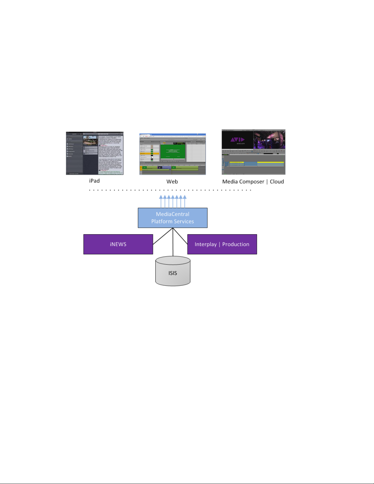
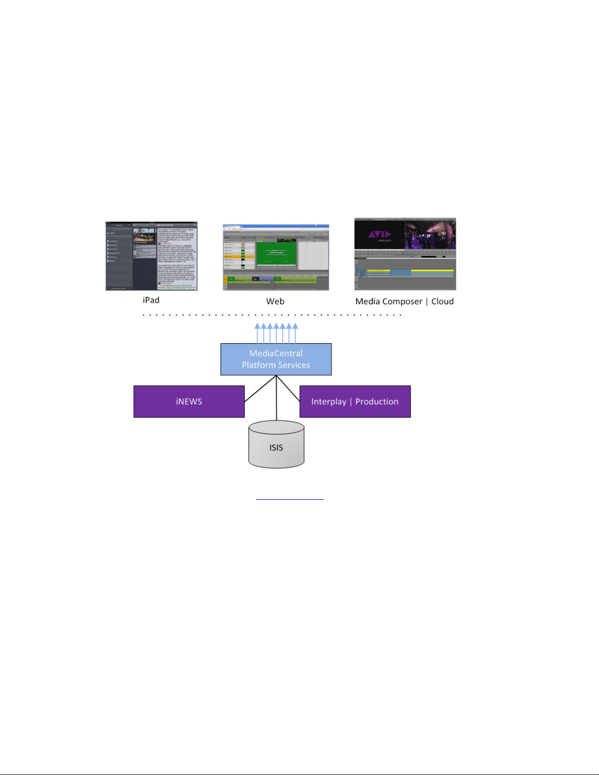
MCS Connectivity
Before examining specific deployment optio ns it can be helpful to have an understanding of
where MCS sits in terms of connectivity to other Avid components.
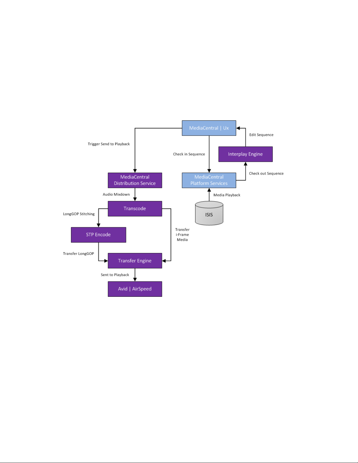
MediaCentral | UX Connectivity
Interplay | MAM Connectivity
17
Page 18

MCS 2.2 Installation and Configuration Guide
Multi-Zone
By default, MCS operates within a single environment such as a particular facility, or department
within a facility. A single facility may in fact house numerous MCS systems, each of which, by
default, operates independently. In a multi-zone configuration, two or more single-zone systems
are joined together. These can even be separated geographically — for example, one server or
cluster could be located in Toronto and another in Munich.
Once joined together as multi-zone environment, user information and media assets are
sharable between the different zones. For example, a user in one zone can find media assets in
remote zones, and transfer them to their local zone for use in their local work. In addition,
multi-zone features centralized user management across all zones.
Multi-zone is configured once you install and set up the independent zones.
For more information, including instructions for configuring a multi-zone environment, see
“P
ART V: MULTI-ZONE CONFIGURATION” on page 163.
Media | Index
MediaCentral UX provides two methods of searching your asset databases. First, federated
search allows you to query single or multiple databases in your local zone to find media
available to your local MediaCentral UX configuration. Second, Media Index allows you to search
using the central index, which comprises both storage and a query engine.
The central index receives its data from the original data sources — generally, the databases of
multiple asset management systems, including Interplay Production, MAM and iNEWS — and
then pushes the data to the service that does the indexing.
Media | Index is installed with MCS by default, b ut the Media Index services are not started. You
configure Media Index after you have installed and set up the MCS system.
You can configure Media Index in both a single- and a multi-zone configuration. If you use MCS
in a multi-zone environment, you must first configure the multi-zone components.
The following key services are needed for delivering media and assets between Interplay
Production workgroups or MediaCentral zones:
• Elasticsearch
18
Page 19

MCS 2.2 Installation and Configuration Guide
• Interplay Media Services Automation
• Interplay Consolidate
• Interplay Delivery
• Production Engine Bus Connector (PEBCo)
For more information, see the Avid Media | Index Configuration Guide.
Deployment Options
MCS is a collection of software services designed to sup po r t a number of Avid enterprise
solutions and deployment options. Since each deployment scenario has different hardware and
software configuration requirements (and playback characteristics), it will be helpful to have a
high-level overview of the deployment of interest before proceeding.
As noted, the installation follows one of these basic deployment models:
• MCS for MediaCentral
o iNEWS only
o Interplay | Production only
o iNEWS and Interplay | Production
• MCS for Media Composer | Cloud
• MCS for MediaCentral and Media Composer | Cloud (Shared MCS)
• MCS for Interplay | MAM
This section provides an overview of each of these deployments.
19
Page 20

MCS 2.2 Installation and Configuration Guide
MediaCentral – iNEWS Only
One of the most straightforward deployments is MCS for MediaCentral in an iNEWS-only
environment; that is, with connections to iNEWS but no connection to Interplay | Production. In
this deployment MCS provides the ability to browse and edit iNEWS content (queues, stories)
from a remote web client. The ability to browse, play and edit associated video requires
Interplay | Production and is not provided by the iNEWS-only deployment.
The iNEWS-only deployment typically requires a RAID 1 (mirrored RAID) for the Linux operating
system. Since MCS is not providing playback of any video assets, there is no need for caching, so
the media cache volume referred to in this guide is not required. Typically, a single MCS server is
sufficient. Two MCS servers configured as a cluster provide high-availability.
Note: The iNEWS-only deployment can be
on smaller, less expensive server hardware.
Refer to the “MediaCentral Platform Services Hardware Guide” for detailed information
on hardware specifications and deployment options. The guide is available on the
Avid
Knowledge Base MCS 2.2 web page.
Deployment Summary:
• Browse and edit iNEWS content
• RAID 1 required
• Media cache volume not required
• Clustering yields high-availability
20
Page 21
MCS 2.2 Installation and Configuration Guide
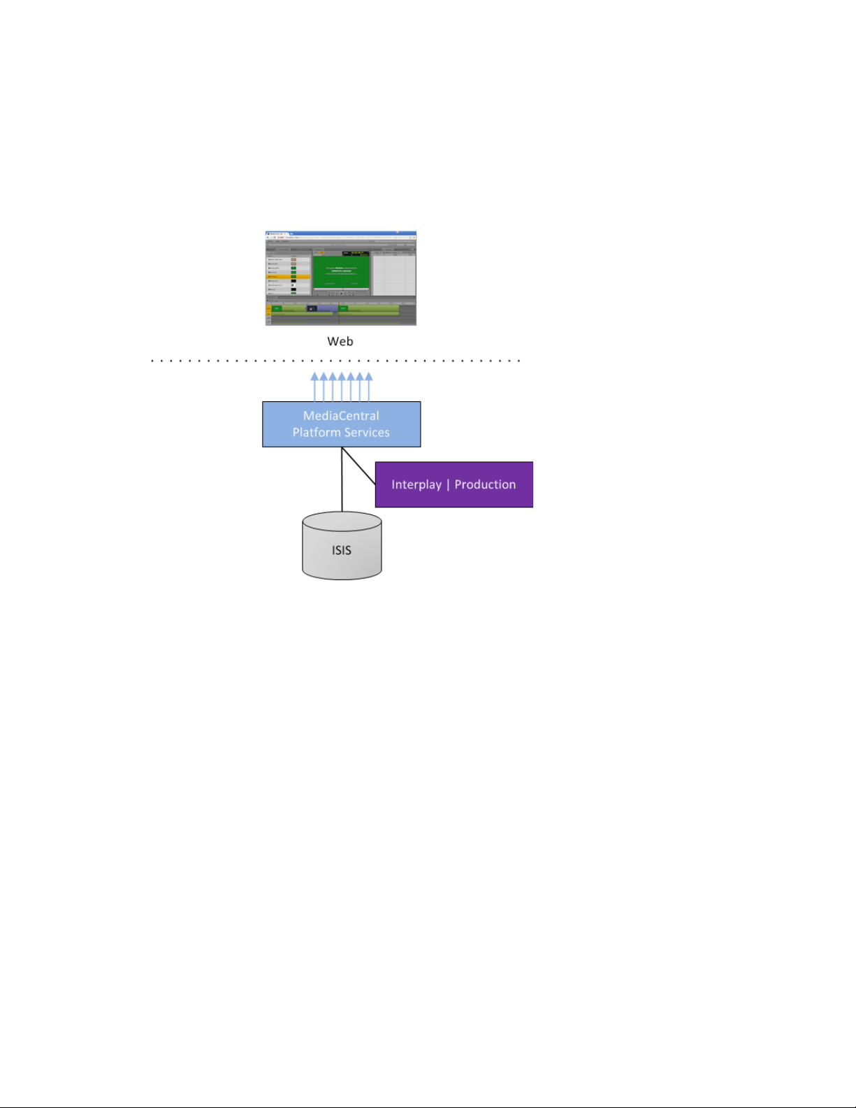
MediaCentral – Interplay | Production Only
MCS for MediaCentral with Interplay | Production has connections to Interplay | Production
only. In this deployment MCS serves layouts for applications, provides user authentication,
manages system configuration settings, and provides proxy-based playback of video assets over
the network to web-based and mobile clients.
images and sound to the remote web-based Media Central | UX c
MCS decodes the source format and streams
li
ent.
This deployment typically requires two HDs configured as a RAID 1 (mirrored RAID) for the Linux
operating system. No iOS devices implies no special caching requirements; however, Multicam
requires a media drive. You can configure two or more MCS servers as a cluster to obtain highavailability and load balancing.
Deployment Summary:
• Browse and play video assets
• RAID 1 required
• Media cache volume required
o RAID 5, or
o RAID 1, or
o Single HD
• Clustering yields high-availability and load-balancing
21
Page 22
MCS 2.2 Installation and Configuration Guide
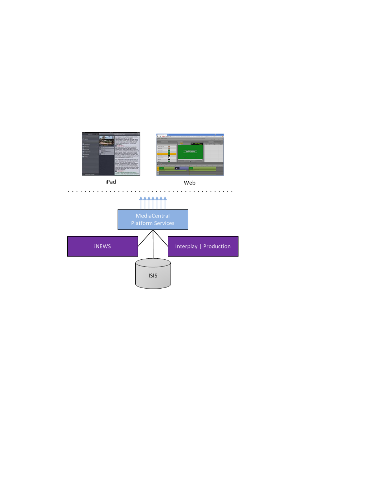
MediaCentral – iNEWS and Interplay | Production
MCS for MediaCentral with iNEWS and Interplay | Production has both iNEWS connectivity and
Interplay | Production connectivity. Similarly to the iNEWS-only deployment, this provides the
ability to browse and edit iNEWS content (queues, stories) from a remote web client. Interplay |
Production connectivity provides the ability to browse, play and edit associated video.
In this deployment MCS serves layouts for applications, provides user authentication, manages
system configuration settings, and provides proxy-based playback of video assets over the
network to web-based and mobile clients. MCS decodes ISIS source formats and streams images
and sound to the remote web-based MediaCentral client.
This deployment typically requires two HDs configured as a RAID 1 (mirrored RAID) for the Linux
operating system. In a configuration where the iOS application is used, the MCS server should
also have a media cache volume. Multicam also requires a media cache volume. You can
configure two or more MCS servers as a cluster to obtain high-availability and load balancing.
Deployment Summary:
• Browse and edit iNEWS content
• Browse and play the associated video assets
• RAID 1 required
• Media cache volume required
o RAID 5, or
o RAID 1, or
o Single HD
• Clustering yields high-availability and load-balancing
22
Page 23
MCS 2.2 Installation and Configuration Guide
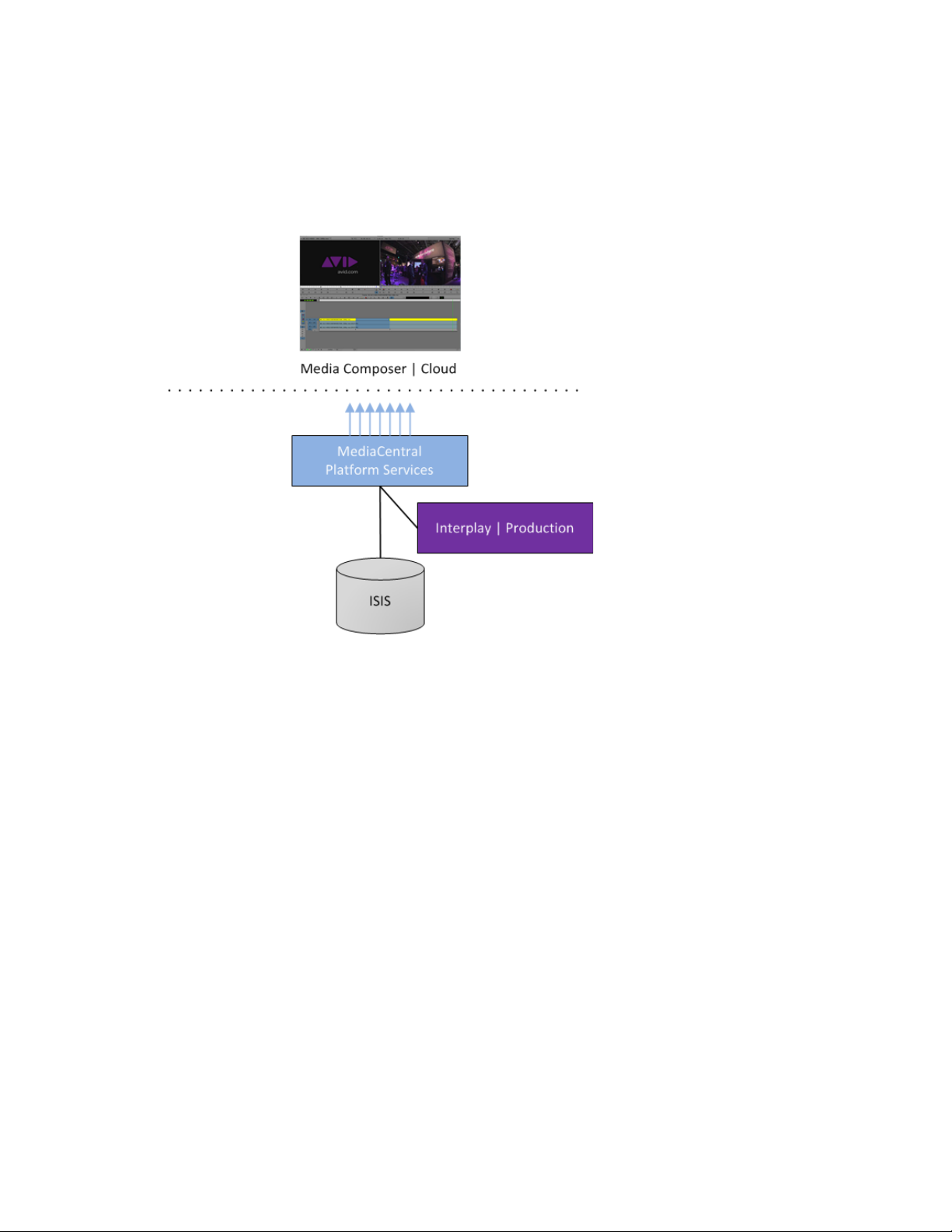
Media Composer | Cloud Only
MCS for Media Composer | Cloud provides playback of different format video assets
reg
i
stered by Interplay | Production and residing on an ISIS. MCS decodes the source format
and streams images and sound to the remote Media Composer | Cloud enabled Media
.
Composer or NewsCutter
This deployment typically requires two HDs configured as a RAID 1 (mirrored RAID) for the
Linux operating system. A media cache is also required. In its most basic form, the Media
Composer | Cloud deployment is a single MCS server.
servers as a cluster to obtain high-availability and load balancing
You can configure two or more MCS
.
Deployment Summary:
• Browse and play the video assets for MediaCentral | Cloud enabled Media Composer
and/or NewsCutter
• RAID 1 required
• Media cache volume required for iOS deployments and/or multicam workflows. It is not
required for Media Composer | Cloud alone.
o RAID 5, or
o RAID 1, or
o Single HD
• Clustering yields high-availability and load-balancing
23
Page 24
MCS 2.2 Installation and Configuration Guide
Both MediaCentral and Media Composer | Cloud (Shared MCS)
MediaCentral and Media Composer | Cloud can easily share the same MCS server(s). In this
deployment, MCS serves layouts for applications, provides user authentication, and manages
system configuration settings. MCS also
different format v
i
deo assets registered by Interplay | Production and residing on an ISIS.
MCS decodes the source format and streams images and sound to the remote web-based
MediaCentral and/or Media Compose r | Cloud c
This is the most sophisticated deployment model, since other elements can also be present,
including iNEWS and/or iOS applications.
provides proxy-base playback over the network of
li
ents
.
This deployment typically requires a RAID 1 (mirrored RAID) for the Linux operating system. In a
configuration with iOS devices (as with iNEWS), the MCS server should also have a media cache
volume. If iOS devices are not deployed, it has no media cache volume requirements; however,
multicam requires a media cache volume. You can configure two or more MCS servers as a
cluster to obtain high-availability and load balancing.
Deployment Summary:
• Browse and play video assets
• Browse and play video assets
for MediaCentral | Cloud enabled Media Composer and/or NewsCutter
• RAID 1 required
• Media cache volume required
o RAID 5, or
o RAID 1, or
24
Page 25
MCS 2.2 Installation and Configuration Guide
o Single HD
• Clustering yields high-availability and load-balancing
Interplay | MAM
In an Interplay | MAM deployment, MCS provides playback of video assets registered as a
browse proxies by Interplay | MAM. The registered browse proxies can reside on standard
filesystem storage, or proprietary storage that provides a stand ard system gateway. The
Interplay | MAM deployment presents two main options – setting up a media cache volume,
and port bonding to improve throughput.
This deployment typically requires a RAID 1 (mirrored RAID) for the Linux operating system.
Under some circumstances – see “Caching in MCS” on page 28
– the MCS server should also
have a media cache volume. You can configure two or more MCS servers as a cluster to obtain
high-availability and load balancing.
Deployment Summary:
• Browse and play video assets
• RAID 1 required
• Media cache volume might be required
o RAID 5, or
o RAID 1, or
o Single HD
• Clustering yields high-availability and load-balancing
25
Page 26

MCS 2.2 Installation and Configuration Guide
MediaCentral
80
TCP inbound
MediaCentral Playback Services (MCPS)
443
Secure TCP
MediaCentral HTTPS calls (communication
843
TCP Inbound
Serving Flash Player socket policy files
5000
TCP Inbound
Playback service (loading assets, serving
MediaCentral
80
TCP Inbound
MediaCentral Playback Services (MCPS)
443
Secure TCP
MediaCentral HTTPS calls (communication
Port Bonding in Interplay | MAM
Port bonding (also called link aggregation) is an OS-level technique for combining multiple
Ethernet ports into a group, making them appear and behave as a single port. Ethernet ports
correspond to the physical connectors in a NIC card where network cables are plugged in.
Bonded ports retain their individual cable connections to the network router or switch.
However, they are seen by the network as a single port.
Port bonding must be configured in “round-robin” mode. In this mode, Ethernet packets are
automatically sent, in turn, to each of the bonded ports, reducing bottlenecks and increasing the
available bandwidth. For example, bonding two ports together in round-robin increases
bandwidth by approximately 50% (some efficiency is lost due to overhead).
In MAM deployments of MCS, port bonding improves playback performance when multiple
clients are making requests of the MCS server simultaneously. With port bonding, more
concurrent playback requests can be sustained by a single server, especially for file-based
playback. File-based playback is a playback method for which a single port-bonded MCS server
can support thousands of requests.
For instructions on port bonding see “
MAM (Optional)“ on page 221.
Port Requirements
The following table lists the MCS port requirements for the client-side applications (the browserbased MediaCentral application and mobile applications). Ports 80 and 443 are required for the
HTTP(S) traffic. In addition, the Adobe Flash Player (running inside the browser) requires ports
843 and 5000.
For more information see the MCS Security Architecture and Analysis document.
Component Port Protocol and
Web application
Appendix B: Configuring Port Bonding for Interplay |
Usage
Direction
HTTP calls (file streaming from MCPS)
Inbound
with MediaCentral server)
mobile applications
26
Inbound
JPEG images, and audio, etc.). Output flow
to client serving inbound request.
HTTP calls (file streaming from MCPS)
with MediaCentral server)
Page 27

MCS 2.2 Installation and Configuration Guide
MediaCentral
80, 443
MCPS
843 (Flash), 80, 5000, 26000
MCS
8000 (optional Admin UI), 8183 (bus cluster info)
ISIS
5000 – 5399 (UPD and TCP)
RabbitMQ
5672 (AMQP), 15672 (Management UI/API)
MongoDB
27017
PostgreSQL
5432
System
22, ICMP, 111, 24007, 24008, 24009-(24009 + number of bricks
The following table lists the server-side port requirements. For more information see the MCS
Security Architecture and Analysis document.
Service Name Port
across all volumes for Gluster). If you will be using NFS, open
additional ports 38465-(38465 + number of Gluster servers). Some
MAM configuration might require additional NFS ports (111, 2049
tcp & udp) or CIFS (137,138 udp and 137,139 tcp). Other filesystems
will have to be checked individually (Isilon, Harmonic Omneon,
etc.).
DNS Requirements
A complete discussion of Domain Name System (DNS) requirements for MediaCentral is a
network topology issue beyond the scope of this document. The principal requirement is that
the host names you assign to the MCS nodes must be resolvable by the DNS name servers
encountered by the MediaCentral client.
Some deployments — such as those making use of Network Address Translation (NAT) — can
fall short when the DNS name resolution process succeeds from inside the corporate firewall,
but fails from outside. In such cases, end-users can log in to MediaCentral and browse storage,
but clips refuse to play.
Note: Currently, connecting to MediaCentral through NAT is supported only for single-server
configurations, not clusters.
The following diagram illustrates the process by which the MediaCentral client uses DNS to
establish a playback session. In particular, note that if the fully qualified domain name (FQDN)
and host name fail to resolve, the playback session makes use of the private-range IP address
supplied by the load-balancing algorithm running on the master node. This is fine when the
MediaCentral client is operating within the corporate firewall.
27
Page 28
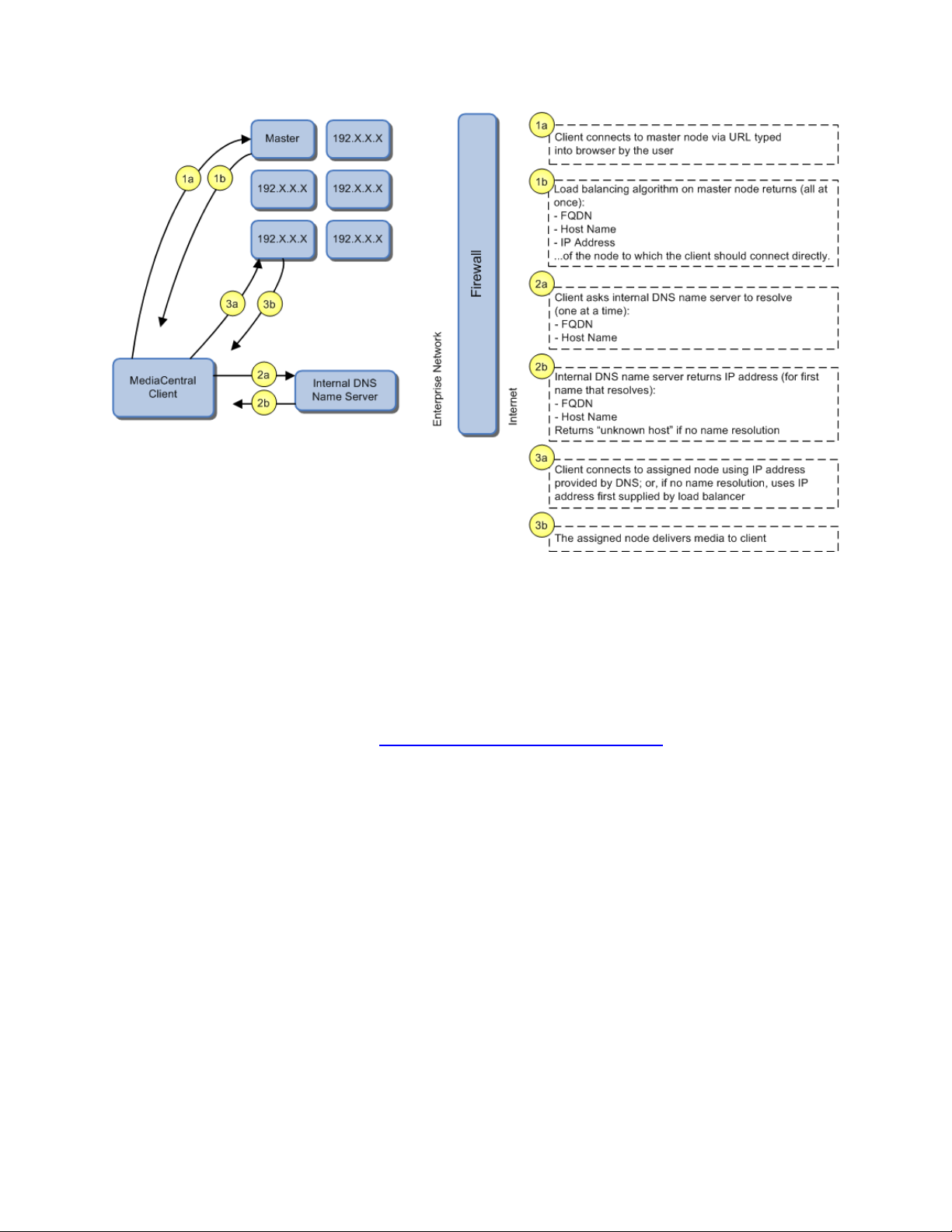
MCS 2.2 Installation and Configuration Guide
However, outside the corporate firewall (not shown) the private-range IP address (e.g.
192.XXX.XXX.XXX.XXX) supplied by the load-balancing algorithm is not accessible. Thus, if the
MediaCentral client is to connect from outside the corporate firewall, the FQDN must also be
resolvable from outside the firewall. For VPN connections this is a non-issue. In the NAT
deployment model, NAT must be configured to resolve the FQDN.
For a browser-based query to validate the data — host, FQDN, IP address — returned by the
load-balancing algorithm see “Validating the FQDN for External Access” on page 180
Caching in MCS
In its work to provide proxy-based playback of video assets over a network, MCS generates
temporary files in certain workflows. For example, MCS deployed for Interplay | MAM typically
generates a multitude of temporary files as it converts proxies from their native MAM formats
into formats compatible with the player. The MCS multicam feature introduced in ICS 1.5
produces numerous temporary files. By default, MCS caches temporary files on the system
drive. Better performance is achieved by allocating a dedicated media cache volume (separate
from the system drive) for the temporary files. In a clustering setup, an open-source software
solution called GlusterFS is also used.
.
Note: All
media caching. The open-source GlusterFS is also required, for file replication between
clustered caches.
28
MediaCentral deployments making use of multicam require a dedicated volume for
Page 29

MCS 2.2 Installation and Configuration Guide
/cache
Stores GlusterFS volumes. It is also used to store some MCS related
/cache/metadata
This is the result of gathering resolution and frame rate info from
/cache/fl_cache
Files rendered for http-based streaming are saved here. For Interplay |
/cache/download
Links to media available in /cache/fl_cache. This is used to obfuscate
/cache/render
Contains jpeg proxies used for the Multicam 2x2 and 3x3 playback.
/cache/spooler
Contains the dynamic relink request queue and replies from the Media
/cache/mob-fetch
The AAF parsing and quality match folder. Cache of per-track DR result
/cache/gluster
Volume used by GlusterFS directly. It is used to support
Note: This document provides instructions for creating a media cache volume as a RAID
5 using multiple disks in the server enclosure. However, other configurations are
possible, including two drives in a RAID 1 configuration, or a single drive. For details, see
the “MediaCentral Platform Services Hardware Guide”.
The Dedicated Caching Volume
All MCS servers require a RAID 1 that mirrors the operating system across two HD drives. Some
deployments also require a media cache volume consisting of the remaining disks in the
enclosure, used exclusively for MCS file caching. In a RAID 5 volume (recommended), the disk
controller automatically distributes (stripes) data across all the disks in the RAID 5, yielding
increased performance and redundancy.
In an MCS server cluster the media cache volume is taken one step further. An open source
software solution called GlusterFS (or just Gluster) is used to replicate the contents of the media
cache volumes across each server in the cluster. In this way, each MCS server in the cluster can
make use of file data already transcoded and cached by the others.
Note: All
volume for caching. The open source GlusterFS is also required, for file replication between
clustered caches.
MediaCentral deployments making use of multicam require a dedicated media cache
The following table summarizes what is stored in the cache volumes:
Component Usage
information.
media file opened by Central. Deprecated.
MAM this means media converted to FLV for file-based playback. For
MediaCentral UX this includes media converted to Mpeg2TS for iOS
playback (e.g. iPhone, iPad).
the path to the media and simplify the link for iOS playback.
Index (MI).
in a format internal to ICS.
/cache/fl_cache, /cache/download and /cache/render.
29
Page 30

MCS 2.2 Installation and Configuration Guide
Caching for Interplay | MAM
For caching, it is important to understand how MAM browse proxies get from proxy storage to
the MAM desktop. For each playback request, MCS does one of the following:
• File-based playback (native): When MAM proxies are in a format that an Adobe Flash-
based player can play natively, MCS serves the proxy file as-is to the remote web-based
client. Adobe Flash-based players natively play MP4-wrapped h.264/aac or FLV. This is
the least CPU-intensive playback mode.
• File-based playback (alternate): When file-based playback requests are made of proxy
formats that cannot be played natively by an Adobe Fl a s h-based player, MCS transcodes
the proxy into FLV, which is stored in the MCS file cache on the media cache volume.
This is then served to the remote web-based client. MCS regularly scans the media
cache, and, when necessary, the least-requested files are purged.
The above playback method has a one-time CPU hit on initial playback request for each
asset, but is subsequently very light because the same cached file is served.
• Frame-based playback: This playback mode is the same one used by MediaCentral, and
is required in MAM for “growing file” workflows and variable-speed playback. In this
case MCS decodes the proxy and streams images and audio to the remote web-based
client frame-by-frame. This is the most CPU-intensive playback mode.
MCS for Interplay | MAM requires a dedicated media cache volume when registered browse
proxies include formats that cannot be natively loaded in the Adobe Flash player. For example, if
MAM registered browse proxies are MPEG-1, Sony XDCAM, MXF or WMV, a media cache
volume are needed in MCS. This guide includes instructions for setting up a RAID level 5 cache.
Caching for iOS Devices in MediaCentral
In a MediaCentral deployment where an iOS application is used, the MCS server should have a
dedicated media cache volume.
Caching for MediaCentral | Cloud
Media Composer | Cloud
Composer and/or NewsCutter). With the introduction of multicam support for MediaCentral
| Cloud (in ICS 1.5) there is a lso a dedicated media cache volume requirement for
MediaCentral | Cloud. This is a result of server-side caching of the multicam “grid” of proxy
images. MediaCentral | Cloud continues to cache video and audio locally.
Working with Linux
caches the video and audio it receives locally on the editor (Media
As noted, RHEL is a commercially supported, open source version of the Linux operating system.
If you have run DOS commands in Windows or have used the Mac terminal window, the Linux
environment will be familiar to you. While many aspects of the MCS installation are automated,
much of it requires entering commands and editing files using the Linux command-line.
30
Page 31

MCS 2.2 Installation and Configuration Guide
/
The root of the filesystem.
/dev
Contains device files, including those identifying HD partitions,
Note: RHEL is not free, and Avid does not redistribute it or include it as part of the MCS
installation. RHEL licensing and support options are covered in the “MediaCentral
Platform Services Hardware Guide”.
Installing Linux
Installations on qualified HP servers can use an express process involving a USB key and the
Avid-supplied kickstart (ks.cfg) file. Kickstart files are commonly used in Linux installs to
automate the OS installation. A kickstart file automatically answers questions posed by the Linux
installer, for hardware known in advance.
Since RHEL is a licensable product, redistribution by Avid is not possible. However, the MCS
installation package includes a Windows executable (ISO2USB) for creating a bootable USB drive
from a RHEL installation DVD or image (.iso) file. We us e ISO2USB to prepare the USB drive to
install the MCS components too.
Note: The USB key and kickstart file shortcuts apply only to MCS installations performed
on qualified HP hardware. For non-HP hardware, see “
HP Hardware” on page 211.
Appendix A: Installing MCS on Non-
Linux Concepts
Once RHEL is installed you can begin the work of setting up the server for MCS. This involves
simple actions such as verifying the system time. It also involves more comp l ex act i on s, su ch as
verifying and modifying hardware settings related to networking, and editing files. Depending
on the deployment, you may also be required to create logical volumes, configure port bonding,
and perform other advanced actions.
Advance knowledge of the following Linux concepts will be helpful:
• root user: The root user (sometimes called the “super” user) is the Linux user with
highest privileges. All steps in the installation are performed as root.
• mounting: Linux does not recognize HDs or removable devices such as USB keys unless
they are formally mounted.
• files and directories: In Linux, everything is a file or a directory.
Key Linux Directories
Like other file systems, the Linux filesystem is represented as a hierarchical tree. In Linux
directories are reserved for particular purposes. The following table presents some of the key
Linux directories encountered during the MCS installation and configuration:
Directory Description
USB and CD drives, and so on. For example, sda1 represents the
first partition (1) of the first hard disk (a).
31
Page 32

MCS 2.2 Installation and Configuration Guide
/etc
Contains Linux system configuration files, including the
/etc/udev/rules.d
Contains rules used by the Linux device manager, including
/etc/sysconfig/network-
Contains, amongst other things, files providing Linux with boot-
/media
Contains the mount points for detachable storage, such as USB
/opt
Contains add-on application packages that are not a native part
/usr
Contains user binaries, including some MCS components.
/tmp
The directory for temporary files.
/var
Contains data files that change in size (variable data), including
/bin
/boot
/dev
/etc
/lib
/media
/mnt
/opt
/sbin
/srv
/tmp
/usr
/var
Directory Description
filesystem table, fstab, which tells the operating system what
volumes to mount at mount at boot-time.
network script files where persistent names are assigned to
network interfaces.
In Linux, every network interface has a unique name. If a NIC
card has four connection “ports”, for example, they might be
named eth0 through eth3.
scripts
time network configuration information, including which NIC
interfaces to bring up.
keys. In Linux, volumes and removable storage must be
mounted before they can be accessed.
of Linux, including the MCS components.
the MCS server log files.
Linux Command Line
The Linux command line is a powerful tool that lets you perform simple and powerful actions
alike with equal speed and ease. For example, entering the Linux list command, ls, at the root
directory produces results similar to the following.
# ls
In the above command note the following:
• The pound sign (#) indicates the presence of the Linux command prompt for a user with
root level privileges (the highest privilege level). You do not type a pound sign.
• A non-root level user would see a dollar sign ($) prompt instead.
• Linux commands, paths, and file names are case-sensitive.
32
Page 33

MCS 2.2 Installation and Configuration Guide
ls
Lists directory contents. Use the –l option (hyphen lower-case
cd
Changes directories.
cat
Outputs the contents of the named file to the screen.
clear
Clears screen.
cp
Copies files and directories.
<tab>
Auto-completes the command based on contents of the
|
“Pipes” the output from one command to the input of another.
dmesg
Displays messages from the Linux kernel buffer. Useful to see if
find
Searches for files.
grep
Searches for the named regular expression. Often used in
lvdisplay
Displays information about logical volumes.
man
Presents help (the “manual page”) for the named command.
mkdir
Creates a new directory.
mount
Mounts and unmounts an external device to a directory. A
ps
Lists the running processes.
passwd
Changes the password for the logged-in user.
The following table presents a few of the more commonly used Linux commands.
Command Description
L) for a detailed listing.
command line and directory contents.
For example, typing cd and the beginning of a directory name,
then pressing the tab key fills in the remaining letters in the
name.
| more
For example, to view the output of a command one screen at a
time, pipe into the more command, as in:
ls | more
a device (such as USB key) mounted correctly.
For example, the following use of the find command searches
for <filename> on all local filesystems (avoiding network
mounts):
find / -mount -name <filename>
conjunction with the pipe command, as in:
ps | grep avid
umount
33
device must be mounted before its contents can be accessed.
Page 34

MCS 2.2 Installation and Configuration Guide
scp
Securely copies files between machines (across an ssh
service
Runs an initialization script.
tail
Shows you the last 10 (or n) lines in a file.
udevadm
Requests device events from the Linux kernel. Can be used to
vi
Starts a vi editing session.
Command Mode
: Prefix to commands in command mode
:wq
Write file and quit vi (in command mode)
:q!
Quit without writing (in command mode)
Insert Mode
i Insert text before the cursor, until you press <Esc>
Command Description
connection).
e.g. service avid-all
e.g.
tail <filename>
tail -50 <filename>
tail –f <filename>
The “-f” option keeps the tail command outputting appended
data as the file grows. Useful for monitoring log files.
replay device events and create/update the
70-persistent-net.rules file.
e.g. udevadm trigger --action=add
Linux Text Editor (vi)
Linux features a powerful text editor called vi. To invoke vi, type the vi command followed by
the target file at the command prompt.
$ vi <filename>
Vi operates in one of two modes, insert mode and command mode. Insert mode lets you
perform text edits – insertion, deletion, etc. Command mode acts upon the file as a whole – for
example, to save it or to quit without saving.
• Press the “i” (as in Indigo) key to switch to insert mode.
• Press the colon (“:”) key to switch to command mode.
The following table presents a few of the more useful vi commands.
Key Press Description
34
Page 35

MCS 2.2 Installation and Configuration Guide
I Insert text at beginning of current line
a Insert text after the cursor
A Insert text at end of current line
<Esc>
Turn off Insert mode and switch to command mode.
w Next word
b Previous word
Shift-g
Move cursor to last line of the file
D Delete remainder of line
x Delete character under the cursor
dd
Delete current line
yy
“Yank” (copy) a whole line in command mode.
p Paste the yanked line in command mode.
Key Press Description
For two short and helpful vi tutorials, more complete reference information, and a vi FAQ, see:
35
Page 36

MCS 2.2 Installation and Configuration Guide
Getting Help
For help with Linux commands, the Linux System Manual (“man” pages)
Searching within
To search for a string within a Linux man page, type the forward slash (“/”)
“command not
A common experience for users new to the Linux command line is to
current directory.
cat
Prints the contents of a file to the command line.
| more
Piping (“|”) the output of a command through the more command breaks
less
Similar to the cat command, but automatically breaks up the output in to
less <filename>
Linux Usage Tips
The following table presents tips that will make it easier to work in RHEL.
Tip Description
are easily available by typing the man command followed by the item of
interest.
For example, for help with the ls command, type:
man ls
a man page
found” error
followed by the string of interest. This can be helpful for finding a
parameter of interest in a long man entry.
receive a “command not found” after invoking a command or script that is
definitely in the current directory.
Linux has a PATH variable, but for reasons of security, the current directory
— “.” in Linux — is not included in it by default.
Thus, to execute a command or script in a directory that is unknown to the
PATH variable you must enter the full path to the script from the root
directory (“/”) or from the directory containing the sc r ip t us ing dot-slash
(“./”) notation, which tells Linux the command you are looking for is in the
up the output into sc reen-sized chunks.
For example to view the contents of a large directory one screen at a time,
type the following:
ls | more
screen-sized chunks, with navigation. Useful for navigating large amounts
of text on screen at a time.
For example:
36
Page 37

MCS 2.2 Installation and Configuration Guide
Volumes in Linux
For those more familiar with Windows, the steps to creating usable volume in Linux are similar
to preparing a new HD for use in Windows.
In Windows, you initialize the disk, create a partition, and assign it a drive letter. You must then
format the disk, specify its file system, its allocation unit size, and assign it a volume label.
In Linux, you must also initialize the disk (this takes place during RHEL installation) and create a
partition. You also format the disk and specify its file system and sector size. Volume labels do
not apply, but have a parallel in the Linux device names (for example /dev/hda or /dev/hdb in
the case of HDs).
Linux builds up to a usable volume in a series of “layers”, each building upon the previous. From
lowest to highest they are physical volumes, volume groups, logical volumes. The filesystem is
built on top of the logical volume.
Clock Synchronization in Linux
The basic mechanism for clock synchronization under Linux is the Network Time Protocol (NTP)
daemon, ntpd, which can be used to automatically maintain synchronization of the system clock
with a specified time server. The time server might be a master clock within a firewall, or one of
the numerous time-servers based on an atomic clock and available via the internet. For reasons
of security, it ought to be a Linux NTP server (or compatible solution) within the corporate
firewall.
It is particularly important when setting up a cluster of MCS nodes that each node should have
precisely the same time.
Clock synchronization is covered in “Synching the System Clock” on page 94
.
Time Zones in RHEL
Like most operating systems, RHEL needs to know the time zone in which it is operating. In RHEL
this is set by assigning geographic information and/or a specific time zon e. Fo r exa mp le the
following are all valid time zone specifications in RHEL:
• America/EST
• America/Los_Angeles
• Australia/Sydney
• Brazil/East
• Europe/Amsterdam
The installation script automatically sets the time zone to Eastern Standard Time. You will have
the opportunity to set the time zone to something more appropriate when you boot RHEL for
the first time.
37
Page 38

MCS 2.2 Installation and Configuration Guide
RAIDs in MCS
RAID stands for redundant array of inexpensive (or independent) disks. RAIDs are used in MCS
to provide data redundancy and for efficiency in caching large amounts of data across multiple
disks. On supported HP servers, you implement these RAIDs at the level of the HP disk
controller, using the HP RAID configuration BIOS utility.
MCS makes use of the following RAID types:
• RAID 1: All MCS implementations require a RAID 1 (mirror) for the system (OS) drive.
This RAID provides redundancy in the event of HD failure.
• RAID 5: Certain deployments also require additional disks configured as a RAID 5 (data
striping with parity blocks) for caching file data. This RAID provides redundancy and
increased performance.
Note: This document provides instructions for creating a media cache volume as a
5 using multiple disks in the server enclosure. However, other configurations are
RAID
possible, including two drives in a RAID 1 configuration, or a single drive. For details, see
the “MediaCentral Platform Services Hardware Guide”.
The following deployments typically benefit from the configuration of a media cache volume:
• Interplay | MAM: Interplay | MAM deployments require a media cache volume when
registered browse proxies include formats that cannot be natively loaded by the Adobe
Flash-based player. That is, for non MP4 h.264 browse proxies (such MPEG-1, Sony
XDCAM, MXF, and WMV), media on proxy storage is transcoded to FLV and stored.
• MediaCentral: MediaCentral installations deploying the iNEWS iOS (Apple mobile
operating system) app require a media cache volume. In this case, media on the ISIS are
transcoded to MPEG-TS (MPEG-2 transport stream), and stored.
With regards to particular servers:
• HP DL360: The HP DL360 may have up to 8 drives present. Configure two as RAID 1 for
the system drive. The additional drives (up to 6), if present, can be configured as a
RAID 5 volume for caching per deployment requirements.
• Other Servers: Other servers will have different hard drive capacities. Configure two
drives as RAID 1 for the system drive and the remaining drives as a RAID 5 volume for
caching.
38
Page 39

MCS 2.2 Installation and Configuration Guide
Introduction to Clustering
Redundancy and scale for MCS is obtained by setting up a cluster of two or more servers. Within
the cluster, requests for media are automatically distributed to the available servers. An MCS
server cluster provides the following:
• Redundancy/High-availability. If any node in the cluster fails, connections to that node
will automatically be redirected to another node.
• Scale/Load balancing. All incoming playback connections are routed to a cluster IP
address, and are subsequently distributed evenly to the nodes in the cluster.
• Replicated Cache: The media transcoded by one node in the cluster is automatically
replicated in the other nodes. If another node receives the same playback request, the
media is immediately available without the need to re-transcode.
• Cluster monitoring. You can monitor the status of the cluster by entering a command. If
a node fails (or if any other serious problem is detected by the cluster monitoring
service), an e-mail is automatically sent to one or more e-mail addresses.
Generally speaking, clusters consist of nodes with identical hardware profiles. However, this is
not required. You can use different hardware profiles for the servers in a cluster.
Note: For detailed information on how MCS servers operate in a cluster, see the “MCS 2.1
Clustering Guide”.
Single Server Deployment
In a single server deployment, all MCS services and the MCPS playback service run on the same
server. This server also holds the MCS database and the dedicated media cache volume.
The following diagram illustrates a typical single-server deployment.
39
Page 40

MCS 2.2 Installation and Configuration Guide
Cluster Deployment
In a cluster deployment, there is one master-slave pair of nodes (providing high-availability and
failover), and additional nodes supporting transcoding (for scale and load-balancing). In a
cluster, all MCS traffic is routed to the master node. Player requests, handled by the MCPS
playback service, are distributed by the master to all available nodes. Key MCS services and
databases are replicated on the slave node, which is ready to assume the role of master at any
time. Other nodes perform transcoding, but do not participate in failovers; that is, they do not
take on the role of master or slave.
The following diagram illustrates a typical cluster deployment.
Multicast vs Unicast
Network communication can be of three basic types: unicast, multicast and broadcast. Unicast is
a one-to-one connection between client and server, with data transmitted to a single IP address.
Multicast transmits to a set of hosts configured as members of a multicast group, and relies on
multicast enabled routers to replicate and forward the data. Broadcasting submits data to an
entire subnetwork.
MCS clustering supports both unicast and multicast. The default configuration, as set up by the
cluster installation script (and covered in the body of this guide) is for multicast. For facilities
lacking multicast enabled routers, you will need to configure clustering for unicast. Unicast
configuration effort is covered in “Appendix F: Unicast Support in Clustering” on page 231
40
.
Page 41

MCS 2.2 Installation and Configuration Guide
Working with Gluster
Recall that the MCS server transcodes media from the format in which it is stored on the ISIS (or
standard filesystem storage) into an alternate delivery format, such as an FLV or MPEG-2
Transport Stream.
In a deployment with a single MCS server, the MCS server maintains a cache where it keeps
recently-transcoded media. In the event that the same media is requested by the web client
again, the MCS server delivers the cached media, avoiding the need to re-transcode.
In an MCS cluster, the cache ma intained by each MCS server is replicated across the others.
Each MCS server sees and has access to all the media transcoded by the others. When one MCS
server transcodes media, the other MCS servers can also make use of it, without re-transcoding.
The replication process is set up and maintained by Gluster, an open source software solution
for creating shared filesystems. In MCS, Gluster manages data replication using its own highly
efficient network protocol.
For more information on Gluster, see: http://www.gluster.org
Note: The correct functioning of the cluster cache requires that the clocks on each server in
the cluster are set to the same time. This is done in “
HP Power Saving Mode” on page 70.
.
Setting the System Clock and Disabling
41
Page 42

MCS 2.2 Installation and Configuration Guide
PART II: INSTALLING & CONFIGURING
42
Page 43

MCS 2.2 Installation and Configuration Guide
1
Appendix J: Installation Pre-Flight Checklist
1–2 hr
Make sure you have all the information related to the server hardware
2
Before You Begin
varies
A quick check to make sure you have everything in place for an efficient and
3
Obtaining the Software
varies
If you are missing any software, this section tells you how to obtain it.
4
Preparing the MCS Installation USB Key
1 hr
In this procedure, you create the USB key you will use to install the MCS
5
Installing the Network Interface Cards
30 min
This step explains the slots where the NIC cards should be placed to simplify
6
Setting the System Clock and Disabling HP Power Saving Mode
15 min
Before installing the Operating System, you must make a few changes in the
7
Setting Up the RAID Level 1 Mirrored System Drives
5 min
You make use of two of the server’s hard disks to create a mirrored RAID
8
Setting Up the RAID Level 5 Cache Drives
5 min
In this step you create a RAID 5 disk array for the file cache used by MCS to
Installation Workflow
The following table describes each of the main installation steps.
If you are setting up a server cluster, be sure to read “Clustering Workflow” on page 129
Step Task Time Est.
too.
varies
(including disk drives and NIC cards in the enclosure), network topography,
IP addresses, etc., required to perform installation.
successful installation.
software.
Note: This step is for HP servers only. For non-HP installations, refer to the
guidelines in “Appendix A: Installing MCS on Non-HP Hardware” on page
211.
the software installation and configuration, and what connections need to
be made.
BIOS.
disk array for the operating system. This is done in the BIOS.
store proxies.†
Note: This step is required only if your Interpla y | MAM deployment
requires a file cache, or you are deploying iOS devices in MediaCentral.†
43
Page 44

MCS 2.2 Installation and Configuration Guide
9
Installing RHEL and the MCS Software
20 min In this step you install RHEL and MCS on the RAID 1 disk array.
10
Booting RHEL for the First Time
10 min
Like most operating systems, the first time you boot RHEL you need to set
11
Editing the Network Connection
15 min
In this step you make sure the physical interface used to connect the MCS
12
Synching the System Clock
5 min
With the network connections established and verified, you can set up the
13
Creating the File Cache on the RAID
15 min
Here, you tell MCS to use the RAID 5 disk array for its file cache.
14
Appendix B: Configuring Port Bonding for Interplay | MAM (Optional)
20 min
Configure multiple network interfaces to appear to the network as a single
15
Configuring MCS for Interplay | MAM
5 min
Configure MCS to mount the file systems on which Interplay | MAM browse
16
Installing the MediaCentral Distribution Service
5 min
Install and configure the Interplay service that coordinates jobs with Avid
17
Configuring MCS for MediaCentral and/or Media Composer | Cloud
10 min
Perform the needed configuration steps so MCS and its built-in player can
Step Task Time Est.
some system information. It is minimal, in the case of RHEL.
server to the network is called eth0.
system to synchronize its clock with a Linux Network Time Protocol (NTP)
server.
Note: This step is required for all deployments using the MCS multicam
feature. It is also required for certain Interplay | MAM deployment, or if you
are deploying iOS devices in MediaCentral.†
IP address for higher throughput.
Note: This step is optional.
proxies reside.
Configure Interplay | MAM to use the MCS server or server cluster
Media Services. This step is performed on a Windows machine in the Media
Services network.
Note: MCDS is only required for MediaCentral, and requires Interplay |
Production.
communicate with Interplay | Production and the ISIS client(s). Once
configured, you can verify video playback.
44
Page 45

MCS 2.2 Installation and Configuration Guide
18
Replicating the Cluster File Caches
30 min
If you are creating a cluster of MCS nodes, we recommend that you replicate
19
Setting up the Server Cluster
2-3 hr
Installing MCS on more than one server and create a server cluster provides
20
P
5 min
Presents monitoring and logging requirements, and a technique for verifying
†
MediaCentral installations deploying the iNEWS iOS (Apple mobile
Step Task Time Est.
(mirror) the RAID 5 file cache volume across each server in the cluster.
Note: This step is required only if your Interplay | MAM deployment
requires a file cache, or you are deploying iOS devices in MediaCentral.†
numerous benefits, including high-availability and failover protection.
Note: Setting up a server cluster can be a requirement, depending on the
details of your deployment model.
ART V: POST-INSTALLATION
that cluster failover performs as expected.
operating system) app require a RAID 5 cache volume. In this case, media on
the ISIS are transcoded to MPEG-TS (MPEG-2 transport stream), and stored.
In an iNEWS-only deployment —that is, with connections to iNEWS but no
connection to Interplay | Production, hence no video playback — no RAID 5
is required
Interplay | MAM deployments require a RAID 5 cache volume when
registered browse proxies include formats that cannot be natively loaded by
the Adobe Flash-based player. That is, for non MP4 h.264 browse proxies
(such MPEG-1, Sony XDCAM, MXF, and WMV), media on proxy storage is
transcoded to FLV and stored.
45
Page 46

MCS 2.2 Installation and Configuration Guide
Before You Begin
Make sure you have everything in place to ensure an efficient and successful installation. Do not
proceed with the installation if something is missing.
Security Updates
Important: Red Hat has issued security advisories for RHEL 6.5. Once you have installed the
operating system, please take a moment to resolve the security vulnerabilities. For
instructions, see the “Security Updates” section in the MediaCentral Platform 2.2 ReadMe.
Make Sure the Host Solutions Are Installed and Running
The host system(s) for the deployment must already be installed, set up, and running, for
example:
¨ iNEWS
¨ Interplay | Production
¨ Media Composer | Cloud or NewsCutter
¨ Interplay | MAM
¨ ISIS
Make Sure You Have the Following Items
The following items are needed for the installation:
¨ MCS server(s), physically connected to the network and/or ISIS
¨ MCS (MediaCentral_Services_<version>_Linux.zip)
¨ RHEL installation image (.iso) file or DVD media
¨ Gluster RPM packages (optional )
¨ MediaCentral Distribution Service (MediaCentral only)
¨ 16GB USB key (for installations on supported HP hardware)
¨ Windows XP/Vista/7 laptop or desktop computer with an Internet connection and a
supported web browser (e.g. Google Chrome)
For Interplay | Production deployments using send to playback (STP), the following software is
also required (and should be installed before proceeding):
¨ Interplay STP Encode
Note: Interplay STP Encode is only required for send-to-playback that includes XDCAM
workflows.
¨ Interplay Transcode
46
Page 47

MCS 2.2 Installation and Configuration Guide
If you are missing software, please see “Obtaining the Software” on page 50.
Note: It is particularly important that the server(s) on which you are installing the MCS software
should be physically installed in the engineering environment, and the appropriate ISIS and/or
the house network connection(s) should be known to you.
You also require access to the MCS server console(s):
¨ Directly by connecting a monitor and keyboard to the server, or via a KVM (keyboard,
video and mouse) device. Direct access is needed for the initial setup and Linux install,
but is a hindrance in later stages of the install, when it is preferable to open multiple
windows at the same time.
¨ Indirectly (optional) using SSH from another machine’s command prompt or shell, for
MCS software installation and configuration. On Windows, Putty.exe is a good option:
http://www.chiark.greenend.org.uk/~sgtatham/putty/download.html
Make Sure You Can Answer the Following Questions
If you do not know the answers to all of the following questions, review the hardware
specifications in your possession, the deployment model you are pursuing and the
environment into which MCS is being installed, before proceeding.
¨ What kind of server? HP or Other.
• MCS supports MediaCentral and Media Composer | Cloud on HP hardware only.
• MCS supports Interplay | MAM on both HP and non-HP hardware.
• MCS supports deployments that do not require video playback on both HP and
non-HP hardware. An iNEWS-only deployment with connectio ns to iNEWS but
no connection to Interplay | Production in a non-video deployment.
For non-HP hardware, see “Appendix A: Installing MCS on Non-HP Hardware
211 before proceeding.
¨ What kind of install? MediaCentral or Media Composer | Cloud or Interplay | MAM.
While the installation steps are very similar for MediaCentral and Media Composer |
Cloud and Interplay | MAM, the configuration steps are different. For Interplay | MAM,
refer to the Interplay | MAM configuration guide.
¨ What kind of server setup? Single or Cluster.
A server cluster provides high-availability and load-balancing. The OS and MCS install
identically on each server in the cluster, but additional steps are required to configure
the servers as a cluster. Further, some configuration steps are not needed on the nonmaster nodes.
” on page
47
Page 48

MCS 2.2 Installation and Configuration Guide
¨ Do I need a RAID 1? Yes.
Yes. All MCS servers require a RAID 1 that mirrors the operating system across two HD
drives.
¨ Do I need a dedicated media cache volume (e.g. RAID 5)? Yes or No.
Almost all MediaCentral deployments require a dedicated media cache volume, for the
multicam caching requirements. This includes MediaCentral | Cloud deployments. The
single exception is the iNEWS-only deployment. However, if the iNEWS iOS application is
used, a dedicated media cache volume is required.
In addition, some Interplay | MAM generate a great number of temporary files as MCS
converts proxies from their native MAM formats into formats compatible with player.
Those MAM deployments require a dedicated media cache volume.
For details, see “Caching in MCS” on page 28
.
Note: This document provides instructions for creating a media cache volume as a
RAID 5 using multiple disks in the server enclosure. However, other configurations are
possible, including two drives in a RAID 1 configuration, or a single drive. For details, see
the “MediaCentral Platform Services Hardware Guide”.
¨ Static or Dynamic IP addresses?
All network interface ports and bonded ports (optional) require IP addresses. While
these can be dynamically assigned (via DHCP) or static, static IP addresses are
recommended. Work with your network administrator to make the correct
determination. Static IP addresses are the only option for clustering.
¨ Does the Interplay | MAM installation require port bonding? Yes or No.
Normally, on a server with multiple network interfaces (i.e. Ethernet connectors), each
interface has its own IP address. However, MCS servers in Interplay | MAM can benefit
from port bonding, in which several network interfaces appear as a single IP address.
Port bonding is an optional installation feature for Interplay | MAM deployments only.
For more information:
• “Port Bonding in Interplay | MAM” on page 26
.
• “Appendix B: Configuring Port Bonding for Interplay | MAM (Optional)” on
page 221.
¨ Is this a shared MCS setup? MediaCentral and Media Composer | Cloud?
48
Page 49

MCS 2.2 Installation and Configuration Guide
An MCS server or cluster can serve MediaCentral and Media Composer | Cloud
simultaneously. In this case, simply install an MCS server or MCS server cluster as
indicated in this document.
¨ A Multicast or Unicast Network? (Clustering only)
MCS clusters support both unicast and multicas t network communication. This body of
this guide provides instructions for configuring a cluster in a multicast environment.
However, multicast requires multicast enabled routers. If your network does not
support multicasting, follow the instruction in the body of this guide, then perform the
additional configuration steps required for unicast. See “
Clustering” on page 231.
¨ Are you deploying the MediaCentral iNEWS iOS app? Yes or No.
For MediaCentral installations deploying the iNEWS app for iOS (Apple mobile operating
system) devices (such as an iPhone or iPad), a dedicated media cache volume (e.g. RAID
5) is required for server-side caching. In an iNEWS-only deployment —that is, with
connections to iNEWS but no connection to Interplay | Production, hence no video
playback — no dedicated media cache volume is required.
Appendix F: Unicast Support in
¨ What kind of clock setting/synchronization is required?
Clock setting and synchronization play an important role in some deployments,
particularly when creating a cluster. For a discussion, see “
Linux” on page 37.
Clock Synchronization in
Make Sure You Have All the Information You Need
During the MCS installation procedures, you are required to enter a great deal of information
pertaining to the MCS servers, network settings, IP addresses, system administrator email
addresses, and so on. It is important to gather this information before you begin. Waiting until
the information is called for by an installation step will result in considerable delays.
For a list of information required to perform the install, see “
Checklist” on page 244.
Appendix J: Installation Pre-Flight
Make Sure You Change the Default Passwords
For reasons of security it is strongly recommended that you change the default administratorlevel passwords at the first opportunity. The RHEL installation script sets up a default login
password for the root user (the Linux user with administrator privileges). Similarly, MediaCentral
is supplied with a default user name and password for the administrator.
• RHEL: Change the root password when you boot into Linux for the first time.
49
Page 50

MCS 2.2 Installation and Configuration Guide
• MediaCentral: Change the Administrator default password the first time you log in to
the MediaCentral | UX (the MediaCentral UI).
Before you begin obtain the new passwords from the customer where the system is being
installed.
Obtaining the Software
Note: For version information see the MediaCentral Platform 2.2 ReadMe.
To perform the installation, the following software is required
¨ MCS Installation Packages (required): A zip file containing Windows and Linux software
needed for the installation.
¨ RHEL (required): The operating system installed on the server. An installation image
(.iso) file or DVD media is required.
¨ Gluster (optional): An open source software package used to mirror the file caches in a
server cluster.
MediaCentral deployments (excluding iNEWS-only deployments) require the following software:
¨ MediaCentral Distribution Service (MCDS): This Interplay service coordinates jobs with
Avid Media Services for sequence mixdowns and send-to-playback.
Deployments of MediaCentral for Interplay | Production using send to playback (STP) require
the following software:
¨ Interplay STP Encode: This service expor ts and enco des Long GOP media, then passes
the media to the Transfer Engine for a send-to-playback operation. The STP Encode
service supports various XDCAM media formats. Required for XDCAM workflows only.
¨ Interplay Transcode: The Interplay Transcode service mixes down audio for script
sequences and checks the sequence into the Interplay Engine. No video mixdown is
required when sending a script sequence to a playback device.
Note: MCDS, Interplay STP Encode and Interplay Transcode are required for MediaCentral
deployments only (but not iNEWS-only MediaCentral deployments).
Interplay Transcode is required when configuring MediaCentral to connect to an Interplay |
Production Engine.
Interplay STP Encode is only required for send-to-playback that includes XDCAM workflows.
Obtaining the MCS Installation Package
On a Windows machine with an internet connection, log in to your Avid Download Center
account (or Avid Master Account) and download the MCS installation package from the
Download Center (DLC).
The MCS installation package is a ZIP file with a name of the form:
MediaCentral_Services_<version>_Linux.zip
50
Page 51

MCS 2.2 Installation and Configuration Guide
MediaCentral_Services
The MCS Server Installation package.
install.sh
The installation script, for upgrades and installations on non-
iso2usb.exe
iso2usb_README.rtf
Used in creating the MCS installation USB key.
ks.cfg
The Avid-supplied kickstart files for fresh installations and for
For the precise installation package name, see the MediaCentral Platform 2.2 ReadMe.
Note: If the MCS installation package is not available via the DLC, please contact your Avid
representative to obtain it.
The ZIP file contains the following:
Item Description
_<version>_Linux.tar.gz
This compressed tar file contains numerous files, including the
following useful shell script:
ics_version.sh
It outputs version/build information for the following
processes:
• UMS - User Management Service
• ICPS - MediaCentral Playback Services
• ICPS Manager - MediaCentral Playback Services
Manager (player-to-server connection manager)
• ACS - Avid Common Services bus (“the bus”)
• System ID: An 11-digit number used in support calls
that you enter whe n configuring MediaCentral
• ICS Installer - MediaCentral installer
The MediaCentral version information is also available
in the user interface in the Home -> About box.
Once MCS is installed, a symlink is created and you can simply
type the following to execute the script:
ics_version
The MediaCentral version/build number is needed, for
example, when configuring iNEWS. See “Appendix H:
Configuring iNEWS for Integration with MediaCentral” on
page 235.
HP hardware.
iso2usb.patch
iso2usb_LICENSE.html
ks_upgrade.cfg
51
upgrade installations.
Page 52

MCS 2.2 Installation and Configuration Guide
system-backup.sh
Prepares for an upgrade by backing up important data,
Item Description
including system settings, network settings, the Jetty keystore
and application.properties file, and the UMS database.
Obtaining Red Hat Enterprise Linux
Log in to your Red Hat Network account and download the DVD image (.iso) file or purchase a
DVD. Either format can be used for the MCS installation.
Note: At the time of this document’s publication, the RHEL 6.5 ISOs were available by
choosing Red Hat Enterprise Linux Server from the Red Hat Product Downloads page.
Specify Red Hat Enterprise Linux Server (product variant), 6.5 (version) and x86_64
(architecture). Download the Binary DVD (
supported.
Important: MCS requires RHEL 6.5. Do not install any OS updates or patches. Do not
upgrade.
rhel-server-6.5-x86_64-dvd.iso). RHEL 7.0 is not
Obtaining the Storage Controller Driver ISO for the HP ProLiant Gen9 Server
By default the HP ProLiant Gen9 server storage controller does not support RHEL 6.5. You must
manually download the following RHEL driver update disk (.iso) to enable RHEL 6.5 support:
dd-hpsa-18216-x86_64.iso
The driver update disk is available directly from Red H a t, but driver details and a link to the
correct page can be found at the HP Servers Support & Certification Matrices “technical
exceptions” web page:
http://h17007.www1.hp.com/us/en/enterprise/servers/supportmatrix/exceptions/rhel_excepti
ons.aspx
Note: This procedure applies to the HP ProLiant Gen9 server only.
To download the driver disk:
1. Open a web browser and navigate to the HP Servers Support & Certification Matrices
“technical exceptions” web page:
http://h17007.www1.hp.com/us/en/enterprise/servers/supportmatrix/exceptions/rhel
_exceptions.aspx
2. Locate the link to Red Hat by searching for the words “DL360 Gen9” using the browser ’ s
“find on this page” feature.
3. Click on the RHEL6.5 x86_64 link.
You are redirected to the Red Hat web site.
52
Page 53

MCS 2.2 Installation and Configuration Guide
4. Log in to your Red Hat Network account.
5. On the Download Red Hat Enterprise Linux page, locate the driver update disk (.iso):
dd-hpsa-18216-x86_64.iso
6. Click the Download Now button and save the ISO file to your computer.
You will use this driver update disk ISO file later when you create the MCS Installation
USB key.
Obtaining Gluster
Navigate to the download directory at gluster.org containing the GlusterFS version supported by
MCS:
http://download.gluster.org/pub/gluster/glusterfs/3.4/3.4.0/RHEL/epel-6Server/x86_64
Download following packages:
¨ glusterfs-3.4.0-8.el6.x86_64.rpm
¨ glusterfs-cli-3.4.0-8.el6.x86_64.rpm
¨ glusterfs-fuse-3.4.0-8.el6.x86_64.rpm
¨ glusterfs-geo-replication-3.4.0-8.el6.x86_64.rpm
¨ glusterfs-libs-3.4.0-8.el6.x86_64.rpm
¨ glusterfs-server-3.4.0-8.el6.x86_64.rpm
Note: If the specified version of Gluster is no longer available, contact your Avid
representative.
Obtaining Additional Packages
The following software packages can be obtained at the Download Center for Avid Video
Products, via your Download Center account (or Avid Master Account).
• MCDS: The MediaCentral Distribution Service (MCDS) package is found in the list of Avid
MediaCentral packages: http://esd.avid.com/ProductInformation.aspx?id=84
.
Note: The MediaCentral Distribution Service (MCDS) is available from the Interplay
Servers installation media. Open the Installers folder at the top level, open the
CentralDistributionService folder, double-click setup.exe and follow the installation
instructions.
• Interplay STP Encode Provider: The Interplay STP Encode Provider installer is supplied as
part of the Interplay | Production installer package.
• Interplay STP Encode Provider patch: The Interplay STP Encode Provider patch is found
in the list of Avid Interplay patches:
http://esd.avid.com/ProductInformation.aspx?id=76
53
.
Page 54

MCS 2.2 Installation and Configuration Guide
• Interplay Transcode Provider: The Interplay Transcode Provider installer is supplied as
part of the Interplay | Production installer package.
• Interplay Transcode Provider patch: The Transcode patch is found in the list of Avid
Interplay patches: http://esd.avid.com/ProductInformation.aspx?id=76
As noted, the above software is required for MediaCentral deployments only (excluding iNEWSonly MediaCentral deployments). It is not required for Interplay | MAM deployments.
Note: As of ICS 1.5 and Interplay Production 3.0 the Interplay STP Encode and Interplay
Transcode patches are not required. However, the patches are required when configuring
MediaCentral to connect to an earlier version of the Interplay | Production engine (e.g.
Interplay Production 2.3–2.7).
.
Preparing the MCS Installation USB Key
Installing MCS requires a bootable USB key containing all the files required for installing MCS,
including RHEL. In this step you prepare the USB key.
For this procedure you require the following items:
¨ The MCS installation package
¨ RHEL installation image (.iso) file or DVD media
Note: Only RHEL 6.5 OS is supported. Do not install patches, updates, or upgrade to RHEL
7.0.
. For a list of approved RHEL patches, see the “Avid MediaCentral Platform v2.2
ReadMe”.
¨ A 16GB USB key
Note: There have been problems with some USB keys. If the server does not boot from
the USB key, or fails to complete the boot, try using a USB key from another
manufacturer, or a larger sized key.
¨ A Windows XP/Vista/7 laptop or desktop computer
54
Page 55

MCS 2.2 Installation and Configuration Guide
Preparing the HP ProLiant Gen9 Server Installation USB Key
Due to licensing restrictions, Avid is not able to redistribute the RHEL installation media. You
must download the RHEL installation image (.iso) file from Red Hat directly—or get it from the
RHEL Installation DVD that came with your MCS server.
Follow this procedure only if you are installing MCS software components on a supported HP
Gen9 server.
Note: Make sure the RHEL image (.iso) file is accessible locally (preferable) or over the
network from your computer. You should complete this procedure with only the USB key
you are preparing inserted in the server. If you have more than one USB key inserted,
make sure you choose the right one when performing this procedure.
Note: You must not simply drag and drop files onto the USB key. Use the ISO2USB utility to
create USB key, as instructed here.
This section contains three procedures:
1. Preparing the MCS Installation USB Key
Take care to enter the correct values in the ISO2USB dialog.
2. Editing the Kickstart File
Make changes so RHEL is installed on the correct volume
3. Copying the Storage Controller Driver Disk to the USB Key
You will install the new device driver just prior to installing RHEL. For more information,
see “Obtaining the Storage Controller Dri v e r I SO for the HP ProLiant Gen9 Server
page 52.
To prepare the MCS Installation USB key:
1. Log into a Windows laptop or desktop.
2. Format the USB key as a FAT32 volume.
3. Extract the contents of the MediaCentral_Services_<version>_Linux.zip file to the
desktop (or your preferred destination directory).
4. Browse into the newly created MediaCentral_Services_<version>_Linux folder.
5. Double-click iso2usb.exe to launch the application.
” on
55
Page 56

MCS 2.2 Installation and Configuration Guide
RAID 1 & RAID 5
sda
sdb
sdc
RAID 1 only
sda
--
sdb
6. Choose the Diskimage radio button then browse to the RHEL image (.iso) file (named
rhel-server-6.5-x86_64-dvd.iso or similar).
7. Verify the Hard Disk Name and USB Device Name are correct for your deployment.
For example, for a system deploying both a RAID 1 and RAID 5 volumes, enter the
following values in the dialog:
• Hard Disk Name: sda
• USB Device Name: sdc
Note: For those familiar with earlier HP servers, the HP ProLiant Gen9 server identifies
the RAID 1, RAID 5 and USB port with different device names. Therefore, use the values
shown in the following table:
RAID Configuration RAID 1
(“Hard Disk Name”)
RAID 5 USB
(“USB Device Name”)
8. In the “Additional Files” field browse to the MediaCentral_Services_<version>_Linux
folder on the desktop (or wherever you expanded it to) and then select the directory
name.
9. Click OK in the main dialog.
10. A process begins to copy the RHEL image (.iso) file and the MCS installation files to the
USB key.
56
Page 57

MCS 2.2 Installation and Configuration Guide
The process takes 10-20 minutes. Once complete, the USB key has everything it needs
for a complete RHEL and MCS installation.
Note: Copying the RHEL image (.iso) file to the USB key is a one-time process. To install
MCS to more than one server, or to re-install MCS, you do not need to repeat these steps.
To edit the kickstart file:
1. With the Installation USB key still plugged in to the Windows laptop or desktop, open
the kickstart (ks.cfg) file for editing.
The kickstart file contains references to sda and sdb devices. By default:
• sda (and sda1): refer to the USB key.
• sdb: refers to the RAID 1 (OS drive)
You must change the default references to the correct device names for your
deployment.
2. Change every instance of sda (x1) and sda1 (x2) to the correct USB device name.
For example, for a system deploying both a RAID 1 and RAID 5 volumes, edit as follows:
• sda (USB key): change to sdc
• sda1 (USB key): change to sdc1
3. Change every instance of sdb (x5) to the correct RAID 1 device name.
For example, for a system deploying both a RAID 1 and RAID 5 volumes, edit as follows:
• sdb (RAID 1): change to sda
4. Save and exit the file.
To copy the Storage Controller Driver Disk:
1. With the Installation USB key still plugged in to the Windows laptop or desktop, copy
the RHEL driver update ISO obtained earlier to the root directory on the key:
dd-hpsa-18216-x86_64.iso
For more information, see “
Obtaining the Storage Controller Driver ISO for the HP
ProLiant Gen9 Server” on page 52.
2. Rename the ISO:
• Old Name: dd-hpsa-18216-x86_64.iso
• New Name: z_dd-hpsa-18216-x86_64.iso
Renaming the driver ISO is essential, since the installation script attempts to mount the
first ISO it finds as the RHEL ISO. If you do not rename it, the installation will fail.
To prepare for mirroring cluster file caches, proceed to “Copying Gluster to the USB Key
” on
page 59.
57
Page 58

MCS 2.2 Installation and Configuration Guide
Otherwise, proceed to “Installing the Network Interface Cards” on page 60.
Preparing the HP ProLiant Gen8 (or Other ) Server Installation USB Key
Follow this procedure only if you are installing MCS software components on a supported HP
Gen8 server.
Due to licensing restrictions, Avid is not able to redistribute the RHEL installation media. You
must download the RHEL installation image (.iso) file from Red Hat directly—or get it from the
RHEL Installation DVD that came with your MCS server.
Note: Make sure the RHEL image (.iso) file is accessible locally (preferable) or over the
network from your computer. You should complete this procedure with only the USB key
you’re preparing inserted in the server. If you have more than one USB key inserted,
make sure you choose the right one when performing this procedure.
Note: You must not simply drag and drop files onto the USB key. Use the ISO2USB utility to
create USB key, as instructed here.
To prepare the MCS Installation USB key:
5. Log into a Windows laptop or desktop.
6. Format the USB key as a FAT32 volume.
7. Extract the contents of the MediaCentral_Services_<version>_Linux.zip file to the
desktop (or your preferred destination directory).
8. Browse into the newly created MediaCentral_Services_<version>_Linux folder.
9. Double-click iso2usb.exe to launch the application.
10. Choose the Diskimage radio button then browse to the RHEL image (.iso) file (named
rhel-server-6.5-x86_64-dvd.iso or similar).
11. Verify the Hard Disk Name and USB Device Name are correct:
• Hard Disk Name: sdb
• USB Device Name: sda
58
Page 59

MCS 2.2 Installation and Configuration Guide
Note: These values have changed since RHEL 6.0, where the hard disk name was sda and
the USB device name was sdb.
12. In the “Additional Files” field browse to the MediaCentral_Services_<version>_Linux
folder on the desktop (or wherever you expanded it to) and then select the directory
name.
13. Click OK in the main dialog.
14. A process begins to copy the RHEL image (.iso) file and the MCS installation files to the
USB key.
The process takes 10-20 minutes. Once complete, the USB key has everything it needs
for a complete RHEL and MCS installation.
Note: Copying the RHEL image (.iso) file to the USB key is a one-time process. To install
MCS to more than one server, or to re-install MCS, you do not need to repeat these steps.
To prepare for mirroring cluster file caches, proceed to “Copying Gluster to the USB Key
page 59.
Otherwise, proceed to “Installing the Network Interface Cards” on page 60
.
Copying Gluster to the USB Key
To prepare for mirroring the file caches in a cluster setup, copy the GlusterFS RPMs you
downloaded earlier to the USB key.
Note: This step is only for those setting up a cluster of MCS servers in an Interplay |
MAM deployment or an MediaCentral deployment that includes the iNEWS app for iOS
devices. If you think you might set up a cluster in the future, perform this step now to
ensure availability of compatible Gluster software.
For this procedure you require the following items:
” on
¨ A 16GB USB key
¨ glusterfs-3.4.0-8.el6.x86_64.rpm
¨ glusterfs-cli-3.4.0-8.el6.x86_64.rpm
¨ glusterfs-fuse-3.4.0-8.el6.x86_64.rpm
59
Page 60

MCS 2.2 Installation and Configuration Guide
¨ glusterfs-geo-replication-3.4.0-8.el6.x86_64.rpm
¨ glusterfs-libs-3.4.0-8.el6.x86_64.rpm
¨ glusterfs-server-3.4.0-8.el6.x86_64.rpm
¨ A Windows XP/Vista/7 laptop or desktop computer
It is recommended that you copy the files to the MCS installation USB key. (Advanced Linux
users may wish to create a network share to install these components instead.)
To add GlusterFS to the MCS Installation USB key:
1. Log into the Windows laptop or desktop where you saved the Gluster RPM packages.
2. Create a directory called Gluster at the root level on the USB key.
3. Copy the RPM packages to the new directory.
Proceed to “Installing the Network Interface Cards” on page 60
Installing the Network Interface Cards
As already noted, for MediaCentral and Media Composer | Cloud, MCS
services, including playback of v
on an ISIS
web-based MediaCentral and/or Media Composer | Cloud c
For an MediaCentral and/or Media Composer | Cloud installation, the MCS server(s) must be
installed and connected to an ISIS via a Zone 1 (direct), Zone 2 (within the ISIS subnets) or Zone
3 (outside the ISIS subnets) connection. In this case you must use a GigE or 10GigE network
interface.
For Interplay | MAM, MCS provides playback of video assets registered as browse proxies by
Interplay | MAM. The connection required depends on where the browse proxies are stored.
For non-ISIS storage, a connection to the network can be made using one of the server’s built-in
network interfaces. No additional NIC is required. However, if the browse proxies reside on an
ISIS, the connection to the ISIS must be over a Zone 1, Zone 2, or Zone 3 (recommended)
connection, using a GigE or 10GigE network interface.
iNEWS-only deployments do not require any ISIS connection, and can make use of the server’s
built-in network interfaces.
.
MCS decodes the source format and streams images and sound to the remote
i
deo assets registered by Interplay | Production and residing
li
ents
.
provides a number of
.
Note: Refer to the “MediaCentral Platform Services Hardware Guide ” for detailed
information on hardware specifications and deployment options. The guide is available
on the Avid Knowledge Base
60
MCS 2.2 web page.
Page 61

MCS 2.2 Installation and Configuration Guide
Myricom 10GigE
HP NC365T 4-Port GigE
HP 366FLR 4-port GigE
Connecting to ISIS Proxy Storage
The HP DL360 G8 has a full height PCI slot in the upper left corner. Use this slot for either the
Myricom 10GigE or the HP NC365T 4-port GigE NIC. The “built-in” Ethernet ports can also be
used, if the server is provisioned with the HP 366FLR 4-port GigE NIC.
HP DL360 Gen8 backplane (indicating Myricom 10GigE):
HP DL360 Gen8 backplane (indicating HP NC365T 4-Port GigE):
HP DL360 Gen8 backplane (indicating HP 366FLR 4-port GigE):
Proceed to “Setting the System Clock and Disabling HP Power Saving Mode” on page “70
61
”.
Page 62

MCS 2.2 Installation and Configuration Guide
Built-in Ethernet Ports
Connecting to non-ISIS Proxy Storage
Interplay | MAM deployments where browse proxies reside on non-ISIS storage do not require
additional NIC cards. They make use of the Ethernet ports built in to the HP server. Visually
verify that one of the built-in ports is connected to the network. For a 10GigE connection to
non-ISIS storage, use a 10GigE NIC of your choosing.
If MAM browse proxies reside on an ISIS, the connection to the ISIS must be over a
Note:
Zone 1, Zone 2, or Zone 3 (recommended) connection, using a GigE or 10GigE network
interface.
HP DL360 Gen8 backplane (showing built-in Ethernet ports):
Note: This applies to Interplay | MAM deployments only.
Proceed to “Setting the System Clock and Disabling HP Power Saving Mode” on page 70
Changing BIOS Settings and Creating RAIDs on the HP ProLiant Gen9
This section presents the BIOS procedures you must perform when installing MCS on an HP
Proliant Gen9 server.
Note the following hot key changes to the HP setup menus:
• F9 – Setup (to System Utilities & BIOS)
• F10 – Intelligent Provisioning (to create RAID1 & RAID5)
• F11 – Boot Menu
• F12 – Network Boot
Setting the System Clock and Disabling HP Power Saving Mode
.
62
(Gen9)
To ensure the smooth installation of RHEL and MCS, the system clock must be set. When setting
up an MCS node cluster, setting the system clocks accurately is particularly important.
Page 63

MCS 2.2 Installation and Configuration Guide
HP servers are frequently shipped with BIOS settings set to Power-Saving mode. MCS is makes
intensive use of the server’s CPUs and memory, especially when under heavy load. You will get
much better performance by ensuring that the server is set to operate at Maximum
Performance.
Note: While setting the system clock and power saving mode can be done after the
installation process, we recommend making the change immediately.
To start the server and access the BIOS:
1. Power up the server.
2. Press F9 at boot to start “System Utilities”.
3. Press Enter to select “System Configuration”.
63
Page 64

MCS 2.2 Installation and Configuration Guide
4. Press Enter to select “BIOS/Platform Configurat i on (RBSU)”.
5. Arrow down and select “Boot Options”, press the Enter key.
6. Press Enter to select “Boot Mode”, press the Enter key.
7. Arrow down and select “Legacy BIOS Mode”, press the Enter key.
64
Page 65

MCS 2.2 Installation and Configuration Guide
8. Press ESC to go back to BIOS/Platform Configurat i on (RBSU)”.
9. Arrow down and select “Power Management”.
10. Press Enter to select “HP Power Profile”.
11. Arrow down and select “Maximum Performance”, press the Enter key.
12. Press ESC to go back to BIOS/Platform Configuration (RBSU)”.
13. Arrow down and select “Date and Time”, press Enter key.
14. Set the date (mm-dd-yyyy) and time (hh:mm:ss).
65
Page 66

MCS 2.2 Installation and Configuration Guide
15. Press ESC to go back to “BIOS/Platform Configuration (RBSU)”.
16. Press F10 to save .
17. Press ESC to go back to “System Configuration”.
If prompted, select “Y” to save changes and exit.
18. Press ESC to go back to “System Configuration”.
19. Press ESC to go back to “System Utilities”.
20. Arrow down and select “Reboot the System”.
The server reboots with new options.
Proceed to “Setting Up the RAID Level 1 Mirrored System Drives (Gen9)” on page 66
.
Setting Up the RAID Level 1 Mirrored System Drives (Gen9)
In this step you configure two of the HD drives in the server enclosure as a RAID Level 1 – a
mirrored RAID – where the RHEL and MCS software will be installed. This is done using the
Option ROM Configuration for Arrays utility, in the HP server’s BIOS.
Note: If the list of available disks does not appear as expected, it may be that a RAID has
already been created. Deleting a RAID destroys all the data it contains, so verify it is safe
to do so first.
To set up the mirrored disks for the operating system:
1. Reboot the server and press F10 to select “Intelligent Provisioning”.
2. Select “Perform Maintenance”.
66
Page 67

MCS 2.2 Installation and Configuration Guide
3. Select “HP Smart Storage Administrator”
4. Select “Smart Array P840” from left side menu.
5. Select “Create Array” under “Actions”.
6. Select both 500 GB Drives then select “Create Array”.
7. Verify “RAID 1”, 256 KiB / 256 KiB Stripe Size, 32 Sectors, Maximum Size, Caching
Enabled, then select “Create Logical Drive”.
67
Page 68

MCS 2.2 Installation and Configuration Guide
8. Press the “Finish” button to complete.
Proceed to “Setting Up the RAID Level 1 Mirrored System Drives (Gen9)” on page 66
.
Setting Up the RAID Level 5 Cache Drives (Gen9)
In this step you configure the remaining HD drives in the server enclosure as a RAID Level 5. In a
RAID 5 data is automatically distributed across all the disks in the RAID for increased
performance and redundancy. This is done using the Option ROM Configuration for Arrays
utility, in the HP server’s BIOS.
Note: If the list of available disks does not appear as expected, it may be that a RAID has
already been created. Deleting a RAID destroys all the data it contains, so verify it is safe
to do so first.
Note: This document provides instructions for creating a media cache volume as a
RAID 5 using multiple disks in the server enclosure. However, other configurations are
possible, including two drives in a RAID 1 configuration, or a single drive. For details, see
the “MediaCentral Platform Services Hardware Guide”.
To set up the remaining disks as the MCS cache:
1. Select “Create Array” under “Actions”.
2. Select all 8 450 GB Drives then select “Create Array”.
68
Page 69

MCS 2.2 Installation and Configuration Guide
3. Verify “RAID 5”, 256 KiB / 1.7 MiB Stripe Size, 32 Sectors, Maximum Size, Caching
Enabled, and then select “Create Logical Drive”.
4. Press “Finish” button to complete.
5. Press “X” (top right) to exit. Confirm the exit by clicking “OK” when prompted.
6. Press “Power” button (top right) to exit. Select “Reboot” when prompted.
69
Page 70

MCS 2.2 Installation and Configuration Guide
Proceed to “Installing RHEL and the MCS Software” on page 76
.
Changing BIOS Settings and Creating RAIDs on the HP ProLiant Gen8
This section presents the BIOS procedures you must perform when installing MCS on an HP
Proliant Gen8 server.
Setting the System Clock and Disabling HP Power Saving Mode (Gen8)
To ensure the smooth installation of RHEL and MCS, the system clock must be set. When setting
up an MCS node cluster, setting the system clocks accurately is particularly important.
HP servers are frequently shipped with BIOS settings set to Power-Saving mode. MCS is makes
intensive use of the server’s CPUs and memory, especially when under heavy load. You will get
much better performance by ensuring that the server is set to operate at Maximum
Performance.
Note: While setting the sys tem c lo c k and power saving mode can be done after the
installation process, we recommend making the change immediately.
To start the server and access the BIOS:
1. Power up the server.
2. When the console displays the option to enter the Setup menu, press F9.
The BIOS responds by indicating F9 was pressed.
70
Page 71

MCS 2.2 Installation and Configuration Guide
The ROM-Based Setup Utility appears after a few moments.
3. Choose Date and Time and press Enter.
Date and Time options appear.
Set the date (mm-dd-yyyy) and time (hh:mm:s s ).
4. Press Enter to save the changes and return to the Setup Utility menu.
5. Choose Power Management Options.
Power Management options appear.
6. Choose HP Power Profile.
Power Profile options appear.
7. Choose Maximum Performance.
You are returned to the HP Power Management options menu.
8. Press Esc to return to main menu.
9. Exit the Setup utility Esc and press F10 to save.
The server reboots with new options.
Proceed to “Setting Up the RAID Level 1 Mirrored System Drives” on page 72
.
71
Page 72

MCS 2.2 Installation and Configuration Guide
Setting Up the RAID Level 1 Mirrored System Drives (Gen8)
In this step you configure two of the HD drives in the server enclosure as a RAID Level 1 – a
mirrored RAID – where the RHEL and MCS software will be installed. This is done using the
Option ROM Configuration for Arrays utility, in the HP server’s BIOS.
Note: If the list of available disks does not appear as expected, it may be that a RAID has
already been created. Deleting a RAID destroys all the data it contains, so verify it is safe
to do so first.
To set up the mirrored disks for the operating system:
9. Reboot the server and press any key (spacebar recommended) when prompted to
display the HP ProLiant “Option ROM” messages.
Note: Do not press F9 or F11. Press any key other than F9 or F11 (spacebar
recommended).
Detailed messages now appear as the server boots up.
10. As soon as you see the prompt to enter th e Option ROM Configuration for Arrays utility,
press F8.
72
Page 73

MCS 2.2 Installation and Configuration Guide
Note: The prompt to press F8 can flash by quite quickly. If you miss it, reboot and try
again.
11. From the Main Menu, select Create Logical Drive.
12. Select the following two HD drives in Available Physical Drives:
• Box 1 Bay 1
• Box 1 Bay 2
13. Deselect all the other available HD drives (if any).
14. Ensure RAID 1 is selected in RAID Configurations.
73
Page 74

MCS 2.2 Installation and Configuration Guide
Note: In older firmware versions, the choice presented may be RAID 1+0. Since you
are only using two HD drives, this is identical to a RAID 1.
15. Ensure Disable (4GB maximum) is selected in Maximum Boot partition:
16. Ensure nothing is selected in Parity Group Count.
17. Ensure nothing is selected in Spare.
18. Press Enter to create the logical drive.
A message appears summarizing the RAID 1 setup.
19. Press F8 to save the configuration.
A message appears confirming the configuration has been saved.
20. Press Enter to finalize the RAID 1 setup.
Note: Do not press the Escape key to exit, since this reboots the server. Wait until you have
set up the RAID 5 cache drives (optional) or have inserted the USB key.
Proceed to “Setting Up the RAID Level 5 Cache Drives” on page 74
(if applicable).
Otherwise, insert the USB key and proceed to “Installing RHEL and the MCS Software” on page
76.
Setting Up the RAID Level 5 Cache Drives (Gen8)
In this step you configure the remaining HD drives in the server enclosure as a RAID Level 5. In a
RAID 5 data is automatically distributed across all the disks in the RAID for increased
performance and redundancy. This is done using the Option ROM Configuration for Arrays
utility, in the HP server’s BIOS.
Note: If the list of available disks does not appear as expected, it may be that a RAID has
already been created. Deleting a RAID destroys all the data it contains, so verify it is safe
to do so first.
Note: This document provides instructions for creating a media cache volume as a
RAID 5 using multiple disks in the server enclosure. However, other configurations are
possible, including two drives in a RAID 1 configuration, or a single drive. For details, see
the “MediaCentral Platform Services Hardware Guide”.
To set up the remaining disks as the MCS cache:
1. If you are arriving to this procedure from setting up the RAID 1 mirrored system drives,
proceed to Step 3, below.
Otherwise, reboot the server and press any key when prompted (spacebar
recommended) to display the HP ProLiant “Option ROM” messages.
Note: Do not press F9 or F11. Press any key other than F9 or F11 (spacebar
recommended).
Detailed messages now appear as the server boots up.
74
Page 75

MCS 2.2 Installation and Configuration Guide
2. As soon as you see the prompt to enter the Option ROM Configuration for Arrays utility,
press F8.
Note: The prompt to press F8 can flash by very quickly. If you miss it, reboot and try
again.
3. From the Main Menu, select Create Logical Drive.
4. Ensure the HD drives to be included in the RAID 5 are selected in Available Physical
Drives:
• Box 2 Bays 3-8 (typical configuration)
5. Ensure RAID 5 is selected in RAID Configurations.
6. Ensure Disable (4GB maximum) is selected in Maximum Boot partition.
7. Ensure nothing is selected in Parity Group Count.
8. Ensure nothing is selected in Spare.
The following screen snapshot shows a RAID 5 under creation.
75
Page 76

MCS 2.2 Installation and Configuration Guide
9. Press Enter to create the logical drive.
A message appears summarizing the RAID 5 setup.
10. Press F8 to save the configuration.
A message appears confirming the configuration has been saved.
11. Press Enter to finalize the RAID 5.
Note: Do not press the Escape key to exit, since this reboots the server.
Proceed to “Installing RHEL and the MCS Software” on page 76
Installing RHEL and the MCS Software
Use the MCS installation USB key prepared earlier to install MCS on an HP server. It accelerates
the process by installing the RHEL operating system and MCS software components at the same
time. To initiate the process, you simply reboot the server with the USB key inserted.
Caution: If you are in the process of upgrading from an earlier version of MCS — called
ICS in earlier releases — it is a fresh install, and will overwrite your current ICS settings
and databases.
Before proceeding with the upgrade, back up your current settings:
¨ Database: The ICS settings and database using the backup script (system-
backup.sh) provided. See “
Backing up the MCS System Settings” on page 182.
.
¨ SSL Private Key(s): If you deployment makes use of CA-signed certificates, back
up private(s), regardless of the upgrade path.
¨ Corosync Configuration File: If you configured ICS 1.4.x for unicast, you made
changes to the corosync configuration (corosync.conf) file. The installation script
76
Page 77

MCS 2.2 Installation and Configuration Guide
overwrites this file. To preserve your changes, back up the file before beginning
the upgrade, and restore it after.
Note: For workflow details on upgrading to MCS 2.2 from an earlier release, see the MCS
2.2 Upgrading Guide, available from the Avid Knowledge Base
MCS 2.2 web page.
To boot the server from the USB key and run the installer:
1. Before rebooting the server ensure the USB key is inserted.
Note: If you have just created the RAID 1 or RAID 5, press the Escape key to exit the
Option ROM configuration menu to proceed to the boot menu, and boot from there.
Note: For HP installs, an error message may appear: "[Firmware Bug]: the BIOS has
corrupted hw-PMU resources". You can ignore this error. For more information, see:
http://h20000.www2.hp.com/bizsupport/TechSupport/Document.jsp?objectID=c032651
32.
2. Wait for the RHEL Welcome screen to appear.
This screen welcomes you to the installation process and presents different installation
options.
Note: It has been reported that under some circumstances the installation bypasses the
RHEL Welcome screen. This will not affect the install process. The correct installation
choice is always selected by default.
3. If you are installing on an HP ProLiant Gen9 server you must install the RHEL driver to
enable RHEL support for the storage controller before proceeding:
a. Press the Esc key to open the RHEL boot shell.
b. At the boot shell, type the following:
77
Page 78

MCS 2.2 Installation and Configuration Guide
linux dd
c. In the dialog that appears, confirm that you have a driver disk.
d. The installer may prompt you to specify the location of the update. Select the
device name indicating the MCS Installation USB key (e.g sdc). Similarly specify
the partition on the device (e.g. sdc1).
e. Select the driver and select OK:
z_dd-hpsa-18216-x86_64.iso
f. When prompted for more drivers, select No.
The driver is updated, and the installation process continues as described
below.
4. Select “Install Red Hat with ICS” to install a new MCS and press Enter.
Note: If you are upgrading your system, do not use the “Upgrade” option. For upgrading
instructions, see the ”
MCS 2.2 Upgrading Guide”.
The RHEL and MCS packages are installed—this takes about 20 minutes.
Note: Installations on supported HP hardware automatically makes use of a “kickstart”
(ks.cfg) file to accelerate RHEL installation. Normally, the kickstart file operates silently
and invisibly without the need for intervention.
Unable to download kickstart file
If you see the above message, it indicates the partition where the Linux installation
program expects to find the kickstart file (sda) is already in use. The most likely cause is a
KVM with “virtual media” capability reserving the sda partition to facilitate the mapping
of removable drives to the attache d ser ver.
To resolve the issue, disable the virtual media capability. Alternately, unplug the KVM
and connect to the server directly using an external monitor and USB keyboard.
5. If you just created the RAIDs a warning screen appears indicating a device (i.e. the
RAIDs) needs to be reinitialized. This is normal. Select Re-Initialize or Re-Initialize All as
needed.
78
Page 79

MCS 2.2 Installation and Configuration Guide
6. The RHEL installation proceeds.
When you see the “Post-Installation” message, it indicates the MCS installation scripts
are being executed.
7. When the installation process is complete, you are prompted to reboot. DO NOT
REBOOT before removing the USB key.
79
Page 80

MCS 2.2 Installation and Configuration Guide
If you reboot without removing the USB key the server will reboot from the USB key
again and re-launch the installer.
Note: If you pressed Enter by mistake, remove the USB key as quickly as possible (before
the system boots up again). If this is not possible, you need to perform the installation
again.
Proceed to “Booting RHEL for the First Time” on page 80
Booting RHEL fo r the First Time
Like most operating systems, when you boot RHEL for the first time, you need to set up a few
items. In RHEL a “first boot” causes the RHEL Configuration screen to appear, providing access to
system set-up menus.
Note: You can re-enter the first boot set-up menus at any time by typing “setup”
(without quotes) at the Linux command prompt.
Note: Some MCS software components depend on the language for RHEL being set to
English. This is done automatically by the MCS installation scripts. Do not change the
input language afterwards.
The procedures in this section make use of the following information you entered in “
J: Installation Pre-Flight Checklist” on page 244:
¨ Default root password
¨ New Linux root password.
Note: Please contact your Avid representative for the default root password.
.
Appendix
80
Page 81

MCS 2.2 Installation and Configuration Guide
Booting from the System Drive
When installing RHEL and MCS you booted from the MCS Installation USB key. This time you
boot from the system drive where the OS and software were installed.
To boot the server from the system drive for the first time:
Note: If the USB key is still in the server, remove it.
1. Press Enter in the post-installation dialog.
Rebooting the server triggers a first-time boot up from the system drive. The RHEL
Configuration screen appears.
2. From the Choose a Tool menu, select Keyboard Configuration. Press Enter.
81
Page 82

MCS 2.2 Installation and Configuration Guide
3. Choose the Language option for your keyboard.
4. Focus the OK button. Press Enter.
5. From the Choose a Tool menu, select Quit. Press Enter.
6. Log in a the Linux prompt
Default user name: root
default password: _
Note: Please contact your Avid representative for the default root password.
You can re-enter the first boot set-up menus at any time by typing “setup” (without quotes) at
the Linux command prompt.
Proceed to “Security Upd a tes
” below.
Security Updates
Once you have installed the operating system, please take a moment to resolve any outstanding
RHEL security vulnerabilities. For information and links to KB articles with instructions, see the
“Security Updates” section in the MediaCentral Platform 2.2 ReadMe.
Proceed to “Changing the root Password” below.
Changing the
For reasons of security it is strongly suggested that you change the password for the root user.
To change the root password:
1. While logged in as the root user type the Linux change password command:
passwd
2. Follow the prompts to change the password.
Use a strong password that is in accordance with the customer’s password enforcement
policies.
root
Password
Proceed to “Verifying the Date and Time
” below.
Verifying the Date and Time
Although you set the time and date in the BIOS in an earlier step, it is worth verifying that it is
still set correctly before proceeding. Linux takes ownership of the BIOS time and date setting,
and may have altered it during the install.
To verify the date and time:
1. If you have not already done so log in.
Log in as the root user (i.e. username = root).
82
Page 83

MCS 2.2 Installation and Configuration Guide
Note: Please contact your Avid representative for the default root password.
2. To check the date type date and press enter.
The date is displayed.
3. If the date is incorrect, change it. For example, for September 2nd, 2012, at 11:03 a.m.
enter:
date 090211032012
The required format is
MMDDHHmmYYYY. (Month-Date-Hour-Minute-Year)
4. When you press enter the reset date is displayed:
Sun Sep 2 11:03:00 EDT 2012
Proceed to “Setting the Time Zone
” below.
Setting the Time Zone
The installation script sets the location to New York city and the time zone to Eastern Standard
Time. Please customize your setup by setting the location more appropriately. In this step you
edit the RHEL file that controls how the operating system interprets values in the system clock.
Note: This step requires the use of vi, the command-line text editor supplied with RHEL. For
an introduction to vi, see “Working with Linux” on page 30
To set the time zone:
1. Using Linux commands, list the contents of the directory containing RHEL time zone
information:
ls /usr/share/zoneinfo
A list of time zone regions is presented. For example, US time zones are located under
/usr/share/zoneinfo/America (replicates IANA time zone database) and
/usr/share/zoneinfo/US (standard US timezones), European time zones are in
/usr/share/zoneinfo/Europe, and so on.
.
2. Locate the time zone of interest in the subdirectories of /usr/share/zoneinfo (e.g.
US/Eastern) and take note of it for the next steps.
3. Using Linux commands, navigate to the directory containing the clock file read by RHEL
at boot-time:
cd /etc/sysconfig
4. List the contents of the directory:
ls -l
5. Using the Linux text editor vi, open the clock file for editing:
vi clock
83
Page 84

MCS 2.2 Installation and Configuration Guide
6. Locate the ZONE information, and replace “America/New_York” with the appropriate
information, for example:
ZONE="America/Los_Angeles"
Navigate using the arrow keys, then press A (append) and replace the information.
7. Save and exit the clock file by typing the following command from within the vi editing
session:
<Esc>:wq
8. That is, tap the Escape key, then the colon, then type wq and press Return.
The file is saved and you are returned to the Linux prompt.
9. Create the symbolic link RHEL needs to make use of the new time zone information:
ln –sf /usr/share/zoneinfo/<yourzone> /etc/localtime
In the above command, <yourzone> is the path you entered in the clock file (e.g.
America/Los_Angeles).
Creating a symbolic link is more robust than copying. For example, the files in
Note:
/usr/share/zoneinfo contain daylight saving time (DST) information. A symbolic link allows
your system to automatically accommodate changes to DST practices that might arise in the
future. Such changes would be propagated via RHEL updates to the /usr/share/zoneinfo files.
10. Verify the settings using the date command:
date
The local time and time zone should now be shown.
Proceed to “Editing the Network Connections” on page 84
Editing the Network Connections
Under the Linux operating system, every physical network connector, called an interface in
Linux, has a name. By default, when installing RHEL, the installer scans the NIC cards in the
machine and labels the interfaces it finds, in the order it finds them. In this step, you verify that
the interface you want MCS to use has the name eth0. If not, you rename the interface.
Note: This step requires the use of vi, the command-line text editor supplied with RHEL. For
an introduction to vi, see “Working with Linux” on page 30
The procedures in this section make use of the following information:
¨ NIC cards present in the enclosure
.
.
¨ NIC card used to connect the server to the network
¨ Whether your facility uses static or dynamic IP addressing
84
Page 85

MCS 2.2 Installation and Configuration Guide
¨ Whether you are setting up a cluster of MCS server nodes
¨ Facility network settings (static IP address, netmask, default gateway IP, e tc ., as
applicable)
¨ Server name
Note: You collected the above information in “
Appendix J: Installation Pre-Flight Checklist” on
page 244.
Identifying NIC Interfaces by Sight
RHEL provides a simple means for visually identifying the NIC ports on a server, whether they
are active or not. The ethtool command can be used cause ports to blink for a pre-determined
amount of time.
To visually identify a NIC Interface:
1. Use the Linux ethtool command, identify the port currently named eth0 by causing it to
blink for 60 seconds:
ethtool --identify eth0 60
Note the use of a double-dash. In Linux, a single- or double-dash dis tin guis h es options
from arguments. A double-dash often precedes a word (i.e. human readable) option.
The system responds by causing the adapter to blink on the eth0 port.
2. If needed, repeat the above to identify other ports.
Proceed to “Verifying the NIC Interface Name
” below.
Verifying the NIC Interface Name
In this step you verify the NIC interface you are using to connect to the network is correctly
named eth0.
To verify the NIC interface name:
1. Enter the RHEL Configuration screens by typing the following at the command prompt:
setup
2. From the Choose a Tool menu, select Network Configuration. Press Enter.
85
Page 86

MCS 2.2 Installation and Configuration Guide
3. From the Network Configuration menu, select Device Configuration. Press Enter.
A list of NIC cards contained in the server enclosure appears.
4. Use the arrow keys to locate the NIC card used to connect to the network. Press Enter
to view its details.
5. Note the name assigned to the NIC card interface of interest (e.g. eth0, eth1, ethn) and
record it here: _______
86
Page 87

MCS 2.2 Installation and Configuration Guide
6. Perform the action required at each menu (Quit, Exit, etc.) to return to the Linux
prompt.
If the selected NIC card interface is named eth0 proceed to “
Ensuring the NIC Interface Comes
Up at System Startup” on page 89.
If the selected NIC card’s interface is not named eth0, proceed to “Swapping NIC Interface
Names” below.
Swapping NIC Interface Names
If you discover the NIC interface you are using to connect to the network is not named eth0, you
must rename it. You must also rename the NIC interface currently using the name. To make
these changes permanent you must edit the network script file where Linux stores NIC interface
names.
1. Using Linux commands, navigate to the directory containing the network script file
where persistent names are assigned to network interfaces:
cd /etc/udev/rules.d
2. List the files in the directory to see if 70-persistent-net.rules exists:
ls –l
Note: A server with just one installed NIC card does not have a 70-persistent-net.rules file by
default.
3. If needed, create the file:
udevadm trigger –action=add
4. Using the Linux text editor, vi, op en the 70-persistent-net.rules file for editing:
vi 70-persistent-net.rules
5. Locate the lines corresponding to the NIC card you want to name eth0 and the one
already using the name.
Use the arrow keys on the keyboard to navigate the file.
6. Press the A key to append to the end of the line:
NAME="eth0"
7. Change NAME="ethX" (e.g. eth1, eth2, etc.) to the following:
NAME="eth0"
8. Locate the line corresponding to the NIC card that was already using the name eth0 and
rename it:
NAME="ethX"
where “X” is the number you removed in step 5 (e.g. eth1, eth2, etc.); that is, swap the
names.
87
Page 88

MCS 2.2 Installation and Configuration Guide
9. Save and exit the 70-persistent-net.rules file by typing the following command from
within the vi editing session:
<Esc>:wq
That is, tap the Escape key, then the colon, then type wq and press Return.
You are returned to the Linux prompt.
Proceed to “Removing the MAC Address Hardware References
” below.
Removing the MAC Address Hardware References
Even though you renamed a NIC interface to eth0 and made the changes permanent by editing
the network script file, there is one more step. In this step you remove the hardware references
– generally known as MAC addresses – from the affected NIC interface configuration files.
Recall that every NIC card is assigned a unique hardware identifier -- called a MAC address -- by
the manufacturer. The MAC address uniquely identifies the NIC card hardware, and is
permanently stored in the NIC card’s firmware. When Linux scans for NICs, it obtains this
hardware identifier and writes it to an interface configuration file. Further, the Linux installation
scripts create an interface configuration file (e.g. ifcfg-eth0, ifcfg-eth1, etc.) for each NIC
interface found. For example, a NIC card with four network interfaces will have four interface
configuration files.
For each card where you renamed a NIC interface, you must edit the corresponding interface
configuration file -- that was already created by Linux -- and remove the hardware identifier.
Otherwise, Linux will override the changes you made earlier and reassign the old interface
names the next time it boots (or you restart the Linux network services).
To remove the hardware references from the interface configuration file:
Note: This procedure must be performed twice – once for each of the NIC interfaces you
renamed.
1. Using Linux commands, navigate to the directory containing the network scripts files:
cd /etc/sysconfig/network-scripts
2. List the contents of the directory:
ls –l
3. Using the Linux text editor, vi, open the interface configuration file for one of the
renamed interfaces (e.g. ifcfg-eth0):
vi ifcfg-eth0
In Linux, each NIC interface has its own configuration file.
4. Locate the line containing the hardware identifier. It has the following form:
HWADDR = 00:00:00:00:00:00
In Linux, each NIC interface has its own configuration file.
88
Page 89

MCS 2.2 Installation and Configuration Guide
5. Position the cursor on the HWADDR line and press “dd” to remove it. That is tap the
lower case letter D twice.
6. Save and exit the file by typing the following command from within the vi editing
session:
<Esc>:wq
That is, tap the Escape key, then the colon, then type wq and press Return.
You are returned to the Linux prompt.
7. Repeat the above steps for the other NIC interface you renamed (e.g. ethX).
8. Once you have finished removing the hardware references for both the renamed NIC
interfaces, reboot the server to restart the network services and ma ke the effects
permanent:
reboot
Note: You must reboot, rather than simply restarting network services, since you
changed the contents of the /etc/udev/rules.d file, in the previous procedure.
Proceed to “Ensuring the NIC Interface Comes Up at System Startup” below.
Ensuring the NIC Interface Comes Up at System Startup
In this step you verify that the eth0 network interface is set to come up when the system boots.
1. Using the Linux text editor, vi, open the interface configuration file for eth0 for editing:
vi /etc/sysconfig/network-scripts/ifcfg-eth0
2. When you open the file for editing, it should look something like this:
DEVICE=eth0
NM_CONTROLLED=yes
ONBOOT=yes
DHCP_HOSTNAME=$HOSTNAME
BOOTPROTO=static
TYPE=Ethernet
USERCTL=no
PEERDNS=yes
IPV6INIT=no
• ONBOOT=yes must be set to “yes” (without any quotes) so Linux brings up the
port at boot time.
3. Change the ONBOOT entry to “yes” if necessary. Otherwise, there will be no network
connectivity.
4. Save and exit the file by typing the following command from within the vi editing
session:
89
Page 90

MCS 2.2 Installation and Configuration Guide
<Esc>:wq
That is, tap the Escape key, then the colon, then type wq and press Return.
You are returned to the Linux prompt.
Proceed to “Configuring the Hostname and Static Network Route
” below.
Configuring the Hostname and Static Network Route
Now that the NIC interface you will use to connect the MCS server to the network has been
named eth0, you are ready to configure the server to make the connection. This is done using
the RHEL configuration facility.
This procedure make us of the facility network settings information you entered in “
Installation Pre-Flight Checklist” on page 244.
To configure the hostname and static network route for eth0:
1. Enter the RHEL Configuration screens by typing the following at the command prompt:
setup
2. From the Choose a Tool menu, select Network Configuration. Press Enter.
Appendix J:
3. From the Network Configuration menu, select Device Configuration. Press Enter.
90
Page 91

MCS 2.2 Installation and Configuration Guide
A list of NIC cards contained in the server enclosure appears.
4. Use the arrow keys to locate the NIC card and interface named eth0. Press Enter to view
its details
5. Ensure the following information is correctly set:
¨ Default name: eth0
¨ Default device: eth0
¨ DHCP is disabled (Spacebar to disable)
6. Disabling the Dynamic Host Configuration Protocol (DHCP) allows you to enter the
following static network route information:
¨ Facility Static IP address
¨ Facility Netmask
¨ Default Gateway IP
¨ Primary DNS server
¨ Secondary DNS server
7. Select OK. Press Enter.
You are returned to the list of NIC cards in the enclosure.
8. Select Save. Press Enter.
9. From the Choose a Tool menu, select DNS Configuration. Press Enter.
10. Give the machine a name (host name) and enter its DNS information:
¨ Enter the hostname: <machine name>
(e.g. ics-dl360-1)
¨ DNS entries from step 6
¨ If you are using a static IP addresses (recommended), enter the DNS search path
domain
¨ If you are using DHCP, leave the DNS search path domain blank.
91
Page 92

MCS 2.2 Installation and Configuration Guide
Note: The host name indicated above is the host name only (e.g. ics-dl360-1),that is, the
name of the machine. Do not use the fully qualified domain name (e.g. ics-dl360-
1.mydomain.com or ics-dl360-1.mydomain.local).
11. Select Save & Quit. Press Enter.
12. Select Quit. Press Enter.
You may be prompted to login to the server.
13. Verify the DNS Server information has been stored in the RHEL resolver configuration
(resolv.conf) file:
cat /etc/resolv.conf
The information you entered for the DNS search path and DNS servers should be
present in the file.
14. Delete any backup resolver configuration (resolv.conf.save) file that might have been
automatically created by the OS:
rm /etc/resolv.conf.save
Note: Due to a caveat in Linux, if you do not delete the resolv.conf.save file, when you
reboot, Linux overwrites the changes you just made.
15. Remove the USB key (if it is still in the server) and reboot the server:
reboot
Proceed to “Verifying the hosts file Contents” below.
Verifying the
hosts
file Contents
The hosts file is used by the operating system to map hostnames to IP addresses. It allows
network transactions on the computer to resolve the right targets on the network when the
instructions carry a human readable host name (e.g. ics-dl360-1) rather than an IP address (e.g.
192.XXX.XXX.XXX).
By default the hosts file on a computer resolves the machine’s own IP address to localhost. In
this step, you verify the content of the hosts file, and remove any extra entries, if present. In
addition, since the active hosts file can be reset to its default configuration when a server fails or
is rebooted you also verify the system default hosts file.
The active hosts file is located here:
/etc/hosts
The system default hosts file (if present) is located here:
/etc/sysconfig/networking/profiles/default/hosts
92
Page 93

MCS 2.2 Installation and Configuration Guide
Note: You can edit the file /etc/hosts while the system is up and running without disrupting
user activity.
To verify the hosts file:
1. Open the active hosts (/etc/hosts) file for editing.
vi /etc/hosts
It should look similar to the following:
127.0.0.1 localhost localhost.localdomain localhost4 localhost4.localdomain4
::1 localhost localhost.localdomain localhost6 localhost6.localdomain6
The entries shown above map the default localhost IP address (127.0.0.1) to various
forms of localhost, for both ipv4 and ipv6 systems.
2. In some cases, the entries incorrectly includes an explicit call-out of the computer’s own
host name (e.g. ics-node-1).
For example, a machine named ics-node-1 might have additional entries as shown
below (in bold):
127.0.0.1 localhost localhost.localdomain localhost4 localhost4.localdomain4
ics-node-1
::1 localhost localhost.localdomain localhost6 localhost6.localdomain6
ics-node-1
3. If the computer’s own host name is present (e.g. ics-node-1), remove it:
127.0.0.1 localhost localhost.localdomain localhost4 localhost4.localdomain4
::1 localhost localhost.localdomain localhost6 localhost6.localdomain6
4. Save and exit the file (<Esc>:wq).
5. Perform the same actions for the system default hosts file:
vi /etc/sysconfig/networking/profiles/default/hosts
Proceed to “Verifying Network and DNS Connectivity
” below.
93
Page 94

MCS 2.2 Installation and Configuration Guide
Verifying Network and DNS Connectivity
Before continuing, take a moment to verify that network connectivity is now established.
To verify network connectivity:
On any other network connected machine, use the Linux ping command to reach the host in
question:
ping –c 4 <hostname>
For example:
ping –c 4 ics-dl360-1
The system responds by outputting its efforts to reach the specified host, and the results. For
example, output similar to the following indicates success:
PING ics-dl360-1.fqdn.com (172.XXX.XXX.XXX) 56(88) bytes of data
64 bytes from ics-dl360-1.fqdn.com (172.XXX.XXX.XXX):
64 bytes from ics-dl360-1.fqdn.com (172.XXX.XXX.XXX):
64 bytes from ics-dl360-1.fqdn.com (172.XXX.XXX.XXX):
64 bytes from ics-dl360-1.fqdn.com (172.XXX.XXX.XXX):
A summary of the results is also presented.
Proceed to “Synching the System Clock
Synching the System Clock
In this step you set the Network Time Protocol (NTP) daemon to automatically synchronize the
system clock with an NTP time server every 30 minutes. This is done by creating a job for the
Linux cron utility. The cron job runs the NTP daemon, ntpd.
Note: Setting up ntpd to run as a service at startup is also a possibility. However, some
consider it a security risk to run ntpd in “continuous” mode. The technique shown here
keeps the system clock synchronized while minimizing exposure to risk by causing ntpd
to exit after it fetches the correct time.
Note: The use of the iburst option within the cron job is not recommended. It produces
very rapid time shifts and can lead to synchronization problems with other nodes, the
ISIS, and so on.
This procedure makes use of the following information:
¨ In-House NTP server:
To synchronize the system clock:
” below.
1. Verify that the NTP server of interest is reachable by querying it:
94
Page 95

MCS 2.2 Installation and Configuration Guide
ntpdate -q <server_address>
2. Edit the NTP configuration (ntp.conf) file using a text editor (such as vi):
vi /etc/ntp.conf
3. Add a line for the NTP server. For example, if the address of the NTP server is
ntp.myhost.com, add the following line:
server ntp.myhost.com
You can supply the IP address instead (e.g. 192.XXX.XXX.XXX)
4. Comment out any out-of-house servers that may already be present, for security. For
example:
# server 0.rhel.pool.ntp.org
# server 1.rhel.pool.ntp.org
# server 2.rhel.pool.ntp.org
5. Save and exit the file.
<Esc>:wq
6. Set up a cron job by editing (or creating) a file containing instructions for cron:
vi /etc/cron.d/ntpd
7. Add a line with the instructions for cron:
0,30 * * * * root /usr/sbin/ntpd -q -u ntp:ntp
The command above instructs cron to:
• Run the cron job every 30 minutes as root.
“0,30” is a comma-separated list (i.e. run at 0 minutes and 30 minutes). “*” is a
special list indicating every value in the list (i.e. every hour, every day of the month,
every month, every day of week).
• The job is /usr/sbin/ntpd
• The -q switch tells ntpd to exit after it sets the system clock
• The -u switch tells Linux to run the job as user ntp, in user group ntp
The general form of the cron command is the following:
# Minute Hour Day of Month Month Day of Week
# (0-59) (0-23) (1-31) (1-12 or Jan-Dec) (0-6 or Sun-Sat)
8. Save and exit the file.
<Esc>:wq
9. Update the system clock now by querying the NTP server with the NTP daemon:
/usr/sbin/ntpd -q -u ntp:ntp
The system responds with a message similar to the following:
95
Page 96

MCS 2.2 Installation and Configuration Guide
ntpd: time set +9.677029s
The NTP daemon sets the time when there are large changes, and slews (slowly adjusts) the
time for small changes (significantly less than a second). There may be no output for a slew.
10. Verify the system time and date:
date
The system responds with a message similar to the following:
Wed Jul 23 12:41:54 EDT 2014
Proceed to “Creating the File Cache on the RAID
” below.
Creating the File Cache on the RAID
In an earlier step you created a RAID 5 for the cache using the “arrays” utility built-in to the HP
server’s BIOS. In this step you finalize caching. First, you partition the RAID. Next you create a
logical volume for the RAID and mount the MCS cache on it.
For a discussion of caching, see “Caching in MCS” on page 28
For a discussion of RAIDs, see “RAIDs in MCS” on page 38.
Partitioning the RAID
In this procedure you partition the RAID and write the new partition table entry to disk using the
GNU parted disk partitioning utility.
The enclosure contains two devices of interest, the system disk (/dev/sda) and the RAID
(/dev/sdb). Partitioning the system disk was performed automatically by the RHEL installer. You
only need to partition the RAID, as indicated in this section.
Note: Starting with RHEL 6.3, Red Hat creates a GPT volume when the MCS installation
scripts initialize the cache volume during OS installation. GPT volumes must be handled
using the GNU parted utility (rather than the Linux fdisk utility).
.
To partition the RAID:
1. Use the GNU parted utility to ensure the RAID 5 HD device exists:
parted –l
Note: Note the command take a lower-case “L” (not a numerical “one”).
Note: The Linux “fdisk -l” command can also be used to list the devices. However, it
returns the following warning:
WARNING: GPT (GUID Partition Table) detected on '/dev/sdb'! The
util fdisk doesn't support GPT. Use GNU Parted.
2. Find the free space on the /dev/sdb device:
96
Page 97

MCS 2.2 Installation and Configuration Guide
parted /dev/sdb p free
Information similar to the following is displayed:
Model: HP LOGICAL VOLUME (scsi)
Disk /dev/sdb: 2500GB
Sector size (logical/physical): 512B/512B
Partition Table: gpt
Number Start End Size File system Name Flags
17.4kB 2500GB 2500GB Free Space
3. Create a primary partition on the RAID 5 using all the available space (2500 GB in the
sample output provided above):
parted -a optimal /dev/sdb mkpart primary ext2 0% 2500GB
The system might respond with the following message:
Information: You may need to update /etc/fstab
The message can be ignored. You will update fstab when you create the logical volume
and mount the cache for the new partition.
4. Set sdb partition one to type logical volume, and its state to on.
parted /dev/sdb set 1 lvm on
5. Run the parted utility again to list your changes:
parted -l
Model: HP LOGICAL VOLUME (scsi)
Disk /dev/sdb: 2500GB
Sector size (logical/physical): 512B/512B
Partition Table: gpt
Number Start End Size File system Name Flags
1 17.4kB 2500GB 2500GB primary lvm
Notice in the above output the partition now has a partition number, is the primary
partition, and has a logical volume flag. You create the filesystem in the next step.
Creating the Logical Volume, Filesystem and Mounting the Cache
In this procedure you work with the newly partitioned RAID 5 using the Linux Logical Volume
Manager (LVM). The hierarchy of volumes in Linux is as follows: physical volume, volume group
and logical volume.
To create the logical volume and mount the cache:
1. Create the physical volume:
pvcreate --metadatasize=64k /dev/sdb1
97
Page 98

MCS 2.2 Installation and Configuration Guide
Note the name of the physical volume (/dev/sdb1) takes a 1 (one).
LVM feedback indicates the successful creation of the physical volume.
2. Create a volume group, vg_ics_cache, containing the physical volume /dev/sdb1:
vgcreate -s 256k -M 2 vg_ics_cache /dev/sdb1
LVM feedback indicates the successful creation of the volume group.
3. Before creating the logical volume, obtain a value for the volume group’s physical
extents:
vgdisplay vg_ics_cache
A list of properties for the volume groups appear, including the physical extents (Free
PE). Physical extents are the chunks of disk space that make up a logical volume.
Sample output is shown below:
--- Volume group -- VG Name vg_ics_cache
System ID
Format lvm2
Metadata Areas 1
Metadata Sequence No 2
VG Access read/write
VG Status resizable
MAX LV 0
Cur LV 1
Open LV 1
Max PV 0
Cur PV 1
Act PV 1
VG Size 1.09 TiB
PE Size 256.00 KiB
Total PE 4578332
Alloc PE / Size 0 / 0
Free PE / Size 4578332 / 1.09 TiB
VG UUID cyWpGZ-s3PG-8UqH-4TBl-rvBA-33oJ-3uZt0u
Use the “Free PE” value to create a logical volume occupying the entire volume group
(below).
4. Create the logical volume, lv_ics_cache, containing the volume group vg_ics_cache:
lvcreate -l <Free_PEs> -r 1024 -n lv_ics_cache vg_ics_cache
In the above command, replace <Free_PEs> with the value obtained in the previous
step. This is the number before the slash in the “Free PE” line. No unit is needed.
For example:
lvcreate -l 4578332 -r 1024 -n lv_ics_cache vg_ics_cache
Note the first switch in lvcreate is lower case “L”.
98
Page 99

MCS 2.2 Installation and Configuration Guide
LVM feedback indicates the successful creation of the logical volume. Note that Linux
may override the sector size you specified. That is OK.
5. Create a filesystem on the logical volume (i.e. format it):
mkfs.ext4 /dev/vg_ics_cache/lv_ics_cache
Note in the above command you specify logical volume by its Linux block device name
(/dev/<volume_group>/<logical_volume>).
As in other operating systems, formatting in RHEL is a slow operation. Please be patient.
Feedback similar to the following indicates success:
This filesystem will be automatically checked every 38 mounts or
180 days, whichever comes first. Use tune2fs -c or -i to override.
6. Navigate to the directory containing the filesystem table:
cd /etc
7. Open the filesystem table file, fstab, for editing:
vi fstab
8. Add an entry at the end of the file:
/dev/mapper/vg_ics_cache-lv_ics_cache /cache ext4 rw 0 0
This automates the mapping of the logical volume to a file system directory (/cache i n
this case).
5. Save and exit the file by typing the following command from within the vi editing
session:
<Esc>:wq
That is, tap the Escape key, then the colon, then type wq and press Return.
You are returned to the Linux prompt.
6. Mount the volume:
mount /dev/mapper/vg_ics_cache-lv_ics_cache /cache
Alternately, since you added an entry to fstab, you ought to be able to mount the cache
as follows:
mount /cache
Note: If you receive an error indicating the mount point /cache does not exist, create the
cache manually and issue the mount command again:
mkdir /cache
mount /dev/mapper/vg_ics_cache-lv_ics_cache /cache
99
Page 100

MCS 2.2 Installation and Configuration Guide
7. Verify that /cache has been mounted correctly:
df –h
The following information is displayed about the cache: size, used, available, user % and
mount point (mounted on), similar to the following:
Filesystem Size Used Avail Use% Mounted on
/dev/mapper/vg_ics_cache-lv_ics_cache
29G 585M 27G 3% /cache
8. Verify that /cache has the correct ownership and read-write-exec settings:
ls -la /cache
Information is displayed about the cache ownership, similar to the following:
drwxr-xr-x 5 maxmin maxmin 4096 Oct 16 10:02 .
9. If the ownership is of /cache is not set to user maxmin, change its ownership:
chown maxmin:maxmin /cache
10. If the /cache directory does not have its read-write-exec settings are not rwx for owner,
group, other, change the permissions:
chmod 0777 /cache
11. Create the following two cache directories:
mkdir /cache/download
mkdir /cache/fl_cache
12. Change their ownership to user maxmin:
chown maxmin.maxmin /cache/download
chown maxmin.maxmin /cache/fl_cache
13. Change their permissions:
chmod -R 02777 /cache/download
chmod -R 02777 /cache/fl_cache
14. Verify that /cache and its subdirectories now have the correct ownership, read-writeexec settings, and setgid special permission:
ls -la /cache
Updated information is displayed, which ought to be similar to the following:
drwxrwxrwx 5 maxmin maxmin 4096 Mar 22 10:04 .
User maxmin owns the MCS process that writes to the cache. Avid processes will
Note:
create subdirectories in /cache, on an as-needed basis. If you are deploying a cluster, you will
revisit caching later in the installation to replicate the cluster contents using GlusterFS.
100
 Loading...