

Page 1

Avid
Liquid
Installation
Page 2

Chapter Avid Liquid Installation
Site Settings
“Site” refers to the computer system on which Avid Liquid is running and the video peripherals connected to it. Among others, the settings include the selection of connected players and recorders.
These settings, which you can access under Edit > Control Panel > Site tab, apply to all system users and,
therefore, are not saved for an individual user but are called each time the system is restarted.
The Site tab contains the following elements:
Player Settings
Parameters of connected players/recorders/other devices page 3
System Settings
Parameters and information on your computer’s software and hardware equipment page 17
Media Management Settings
Here you can define the drives and directories that should be used for digitizing
For a detailed description of these parameters and options please refer to the Reference Manual, chapter
“Administration”, page 332.
Codec Presets
These topic is also covered in the Reference Manual, chapter “Administration”, page 319.
FX Editors Settings
Settings for render and preview quality, etc. page 23
Plug-In Settings
Information on the storage location for third-party effects and Effect Editors page 25
2
Page 3

Player Settings
Icon Player Set-
tings
Changing Parameters
How to change default values page 4
Settings tab
Device-specific settings such as drive ballistics, available inputs and outputs, etc. page 5
Connections tab
Here you can define the communication and signal interfaces used by your hardware page 15
Player Settings
Double-click the icon Player Settings (via Avid Liquid´s Start Menu > Control Panel >
Site) to specify players and recorders connected to the system and video, audio and
control connections. The dialog box that appears offers two tabs: Settings and Connections.
3
Page 4

Chapter Avid Liquid Installation
How to Change Parameters
This dialog box is similar to Windows Explorer in terms of its organization. The categories that can be
selected appear on the left; to display subcategories, click the plus sign in the box. Use the right-hand
field to adjust the parameters for each category by double-clicking a value, entering one with the keyboard or selecting one from the appropriate drop-down menu.
4
Page 5

Settings Tab
This tab can be used for adjusting the technical parameters of the connected devices.
Avid Liquid recognizes three categories of players and differentiates among them based on the protocols
used for remote control of the devices:
Live -
A virtual player that is not controlled.
i.Link DV -
Controlled via the DV protocol (as per the IEEE 1394 standard). Compatible with all the latest
DV and HDV devices.
Betacam -
A control protocol that is processed via the serial interface as per the RS 422 (or RS 232) standard. More precise than DV i.Link; used in professional environments.
With Windows XP OS it is possible to connect more than one DV device to your computer. All working
DV devices are listed under System Settings > Inputs/Outputs. The device that is selected there
configured here
Settings dialog (page 17).
How to assign and configure new devices page 6
Player Settings
can be
, in the Player Settings dialogs. If you want to switch to another device, turn to the System
Live Input page 8
i.Link DV (IEEE 1394) page 9
Æ Timi ng page 9
Generic Betacam driver (controlled via RS 422)
Æ Timi ng page 10
Æ Functional description page 11
Æ Options page 12
Æ Tape protection page 14
5
Page 6

Chapter Avid Liquid Installation
Assign and Configure Devices
The following options allow you to
select player and recording devices
configure these devices.
The devices that appear under Player Settings are available in the Logging Tool, for EZ Capture (DV
devices only) and in the Record to Tape tool (recorders only). In the default configuration, three players
are configured. You can add additional devices.
Assigned Name
For each default setting, a device has either a model, manufacturer or remote control name (e.g. Sony
Device, LIVE, Generic Betacam driver or i.Link DV). Initially, this is the same name as the one listed
under Default parameters matching (see below). Consequently, you should first
match the name.
You can assign an individual name (such as “Player 1”) to each device. Double-click the default name,
enter the individual name in the edit field, then press
select the dev ice and then
ENTER.
6
Page 7
Player Settings
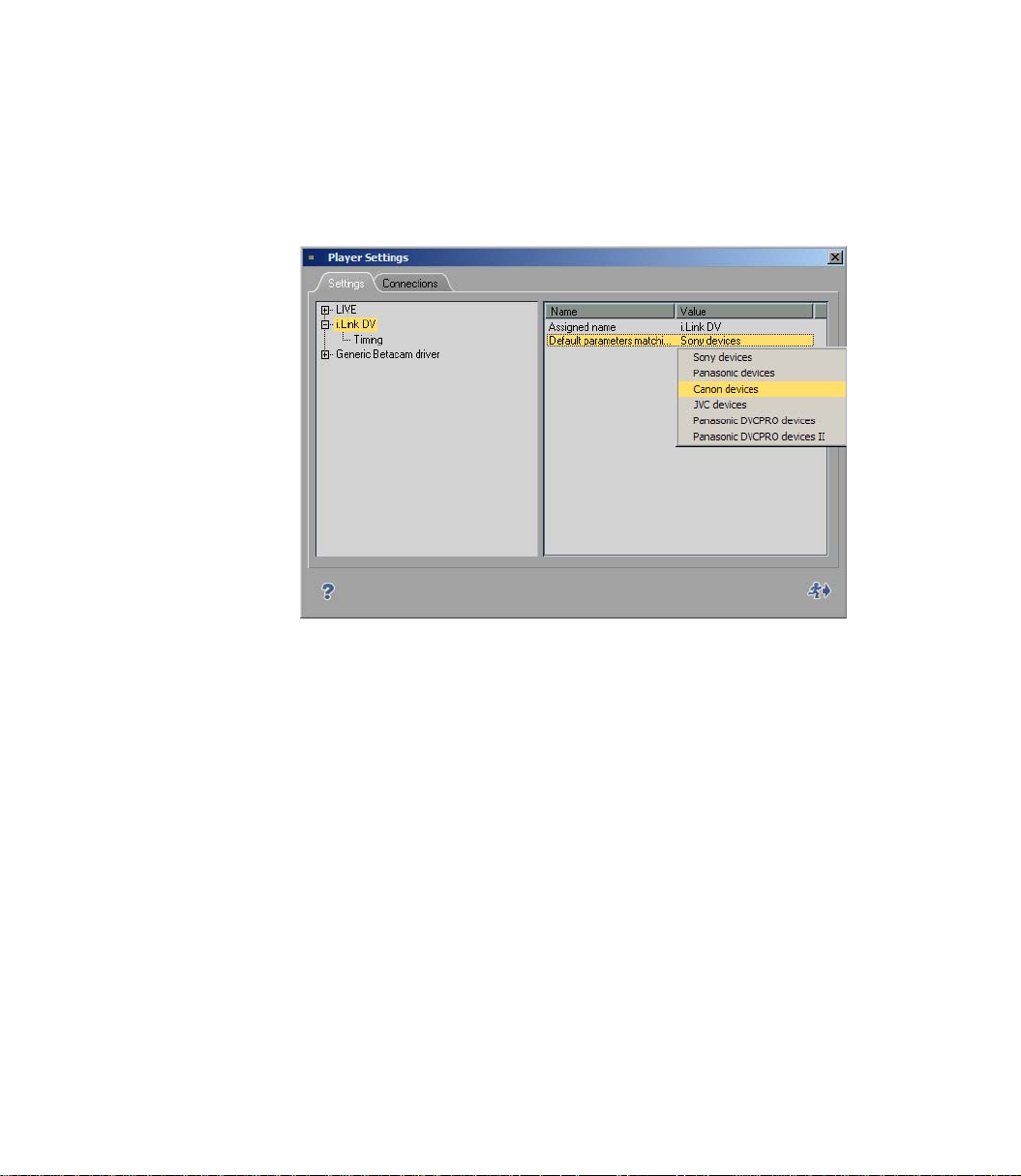
Default Parameter Matching / Select Device
Here you can configure your video devices.
First, click the device or connection name on the left of the dialog, then double-check the manufacturer
name on the right-hand side. Select the manufacturer of the connected device from the list.
Select manufacturer
If necessary, you can enter the exact device name in the line above the manufacturer name. Double-click
this line to edit it and press
Additional device settings are not usually necessary. However, if you have problems controlling the
device, see the information on device timing below.
ENTER to finish editing.
Add Devices/Remove Devices
It is possible to add devices to the list.
1 Right-click somewhere below the list of devices in the left-hand section of the dialog. In the
shortcut menu, select Add.
2 In the submenu, select the matching remote control protocol or an additional Live Player.
3 Select a precalibrated device from the list of devices as described above (Default parameters...)
4 If you like, assign an individual name for the new device (Assign ed Name).
To remove a device from the list, right-click that device and select Remove.
7
Page 8

Chapter Avid Liquid Installation
Live Input (Virtual Live Player)
Use the Live Player if the video or audio signal is not from a controllable source (such as TV) or if you are
controlling the player source using the controls on the device itself. You can assign a user-defined name
for the Live Player. See also “Assigned Name” on page 6.
A remark for users of Avid Liquid in combination with analog input/outputs: Use the Live Player to capture analog signals. With IEEE 1394 (i.Link DV) remote control there is DV in/out exclusively
This restriction does not concern Avid Liquid systems equipped with RS 422 interface. You can use analog inputs in combination with RS 422 control.
Options
You can add TC data to the live input signal or use the supplied TC data of the signal.
1 Click the plus (+) symbol,
2 click Options,
3 and, in the right-hand section, double-click the current Va l u e .
Choose one of three options:
Custom - It defines that a TC value manually specified in the Logging Tool should be used for gen-
erating timecode data. The timecode starts with the value entered in the Posit ion timecode field.
Start/stop the TC counter by clicking Play (toggle button).
See also “Timecode Position Field (A)” on page 115.
.
Time of day - The system time is used for generating timecode data. “Time of day” is only guar-
anteed with a correctly set system clock.
TC count starts immediately after initialization of the Logging Tool.
Video - TC data embedded in the DV input signal. (VITC cannot be used.)
8
Page 9

Player Settings
i.Link DV Devices (IEEE 1394)
i.Link DV is a name for devices connected and remote controlled via a DV interface. Other, more or less
synonymous names are Firewire or IEEE 1394 (the latter is the official standard name). This interface
needs to be integrated in your computer or in the breakout box.
With the exception of timing parameters, there are no further settings to define.
Timing (IEEE 1394, DV)
Double-click the Va l u e you want to edit. Selection varies according to your product version.
Wait After Sending Record [ms]
This value defines the length of time from the moment the record command is sent to the recorder until
the actual Timeline play. When it is set to 5000, you automatically receive a black image for 5 seconds
before the film is recorded.
Wait Before Sending Record [ms]
This value defines the length of time from the moment the Record button in the R ec ord To Ta pe dialog
box is selected until the record command is actually sent to the recorder.
Almost all devices work perfectly with a value of 0. If your recorder does not record despite numerous
attempts, we advise you to increase this value in steps of 1000 ms until the recorder records.
The reason for this problem is that some DV dev ices cannot be switched to record mode until an image is
present and an immediate synchronization was not possible with a value of 0.
Max. Duration of Goto [s]
This entry determines the amount of time your DV device may require to go from one position on the
tape to another position, such as a mark-in.
Preroll [frames]
This value determines the preroll time for Batch Digitize and Record to Tape.
The higher the value, the longer the preroll time. Some DV devices require a preroll time of at least 15
frames in order to guarantee a successful synchronization between Avid Liquid and the DV device.
If a clip cannot be cleanly digitized with Batch Digitize (e.g. the error message “Preroll Position not
found” is issued), Avid Liquid automatically attempts to digitize this clip up to three times.
Send 2 Step commands [on/off]
Some players step field by field, some frame by frame. This means: Some transport the tape by one field,
some by one frame, when a step command is received. This option forces the fieldsteppers among the
players to move frame by frame, when you click the one frame forward tool button: 2 x field steps = 1
frame step.
9
Page 10

Chapter Avid Liquid Installation
Generic Betacam Driver (Controlled via RS 422)
This driver is used to control professional tape decks via a serial cable.
Timing
CAUTION: Change these parameters only when the connected device works inaccurately. With
Liquid
needed for RS 422 control. Please contact your Avid Technology, Inc. dealer.
with RS 422 interface, some of the following options do not apply. A special 232-422 cable is
Avid
Position Request
This default set value should not be changed.
Play TC Delay [Fields]
Adjust this setting until the video is frame-accurately captured by the Logging Too l at the mark-in point.
Use burned-in timecode instead of the ordinary timecode overlay to ensure the results are not affected by
the construction delay of the timecode overlay. To generate a tape with burned-in timecode simply
record the Monitor (Superimposed) Out signal on a second VCR and use this tape as a reference.
Rec TC Delay [Fields]
Place two successive clips on the Timeline and record (Insert) them to tape. Adjust this parameter until
the hard cut from Clip 1 to Clip 2 appears at the proper position on the tape (same position as on the
Timeline).
Edit Delay [Fields]
After having adjusted Rec TC Delay, adjust the edit delay until the recording (Insert) starts at the first
frame of Clip 1.
Note: To obtain reproducible results, clean the area around the insert point before each attempt by
recording over it with a different clip.
10
Encoding delay [fields]
This setting affects tape decks that work with a compressed format (such as DV) but should receive
uncompressed signals. In this case, the uncompressed signal must first be encoded inside the device
before it can be recorded to tape. The result is a delay in the device’s video path (encoding delay). To correct this delay, enter the correction value for the corresponding number of fields here, i.e. for a delay of
two frames, enter a value of 4.
Page 11

Player Settings
Step Emulation Delay [Fields]
As the protocol does not define a definite single-step command this behavior is emulated with a jog command at a speed of 1/10 for a certain period of time. With this parameter you can control how long the
interface command (1 frame forward / backward) is to be maintained to emulate a one-frame step.
Functional Description (RS 422)
The technical options for the connected devices are described here. All entries in the functional description section simply specify the functional features of the device. They are not intrinsically used by the
driver but serve to help the software identify which features should be available if a specific device is
selected.
You may use these options to configure a taylor-made machine, one, for instance, featuring a YUV-SDI
converter at its output, which therefore can be described as being equipped with a SDI output.
NOTE: With
Avid Liquid
Machine Type
The Machine Type property informs the front-end about the recording capabilities of the device. The
following options are available:
Player - the device does not possess any recording capabilities.
Recorder - the device is capable of simple recording, i.e. striping and dumping, but no insert edit.
Assemble Recorder - The device also has assemble mode but not insert mode.
Edit Recorder - in addition to simple dumping, the device is also able to execute insert edits.
(with RS 422 option), some of the following options do not apply.
Digital Audio
If this parameter is activated, the recording device must be equipped with digital audio tracks which
become visible in the Record to Tape tool's track settings dialog box.
Maximum Shuttle Speed
Defines maximum shuttle speed for a device. This parameter controls the mapping of shuttle values
received from the
(assigned to speed x2) and the maximum shuttle position. If improperly specified (usually too high), the
device usually enters the maximum shuttle speed once the control ring/knob is moved past the x2 lock
position.
Avid Liquid Control
(optional control panel) between the second grid point
11
Page 12

Chapter Avid Liquid Installation
Video Outputs
Depending on the individual device you find the following outputs, either assigned by default (Ye s ) or
not available (No):
Composite (CVBS, FBAS)
S-Video (Y/C)
Component (Y/R-Y/B-Y)
SDI
SDTI
SDTI x (hyper-speed transfer 2x, 4x)
The Ye s / N o settings here describe the standard features of the device. You may add outputs according to
your specific studio setup. This serves as cross-references in the Settings > Player Settings > Connection
dialog and defines the inputs that can be assigned to the editing system.
Audio Outputs
Mimics the video logic for audio outputs.
Analog
AES/EBU
SDI
SDTI
The Ye s / N o settings here describe the standard features of the device. You may add outputs according to
your specific studio setup. This serves as cross-references in the Settings > Player Settings > Connection
dialog and defines the inputs that can be assigned to the editing system.
12
Options
Minimum Preroll PLAY [s]
Controls the minimum preroll time used by the driver before automatic preroll adjustment has started
during the initial digitization process. If it becomes apparent during the calibration process that the
device will never lock faster than with 3 seconds preroll, this parameter should be set to 3 seconds to
avoid unnecessary retries during the digitization of the first clip. However, this setting will not negatively
influence the behavior of the driver if the value initially specified is too low. If it is too high, the driver will
take longer than necessary to log a clip.
Page 13

Player Settings
Minimum Preroll REC [s]
Controls the minimum preroll time initially used by the driver before automatic preroll adjustment starts
during the first recording. Do not force the driver to use values less than 5 seconds since, unlike with traditional linear editing suites, actual recording occurs rather infrequently and it is not worth performing
unnecessary retries (which take several multiples of 5 seconds) by starting with a too low record preroll
time.
ClipLink Safe Preroll
This setting affects the digitizing of DV tapes to which the ClipLink technique was applied during
recording. If the camera was switched off between two takes, in some cases the cut between the first take
and the second take may not be precisely flush, which can in turn result in timecode breaks in the preroll.
To avoid problems when digitizing, you can configure a value for the ClipLink safe preroll here. The
default value is three seconds. During these three seconds of preroll time, no data is digitized.
Record Color Frame Selection
Controls the Color Frame Select command sent to the device before any type of recording.
Timecode
Defines which type of timecode should be used for the device in timecode request. The setting can either
be
VITC (Vertical Interleave Timecode)
LT C (Longitudinal Timecode)
CTL (Control Track)
Aut o (VITC/LTC); recommended setting
TC Monitor Accuracy [Frames]
This parameter is required for detecting TC breaks (see the TC break options in the Logging Tool). The
system compares the target and actual values in the current TC. On an ideally synchronized player, the
value can be 0 frames; in actual practice, however, deviations can also occur. For this reason, the default
setting is 3, meaning that deviations of up to three frames are ignored.
Ignore Reference Warnings
Avid Liquid displays an error message when the player or recording device signals an imminent problem
with the sync or reference signal. Set this value On to ignore these warnings.
However, we recommend to pinpoint the cause of the problem, because it may impede the editing accuracy.
13
Page 14

Chapter Avid Liquid Installation
Tape Protection
Standby Off After (Active)
Controls the time in Still mode (Shuttle 0 or normal STOP) after which the device is switched to Standby
Off when the device is being actively used (i.e. it is currently selected as the active device in the Logging or
Re co rd ToTa pe Too l and at least one of these is visible on screen).
Standby Off After (Inactive)
Controls the time in Still mode (Shuttle 0 or normal STOP) after which the device is switched to Standby
Off when the device is not being actively used (i.e. it is currently not selected as the active device in either
the Logging or Record Tool = normal background operation).
14
Page 15

Connections Tab
Use these functions to combine video and audio inputs and outputs of the editing system with the outputs and inputs of the connected players, recorders and live sources. Also select the remote control settings for connected devices.
Begin by specifying (click on device name) in the left field to which recorder, player or live source the
subsequent settings are to apply.
Communication Port (IEEE or RS 422) page 15
Video and Audio Inputs page 16
Video and Audio Outputs page 16
Communication Port
If you have connected a controllable DV device (camera or recorder/player) via the IEEE 1394
interface (as opposed to a non-controllable live source), click the device name or i.Link DV/1394
in the left-hand box and check that IEEE 1394 appears as a Communication Port.
This selection refers to the device that was selected in System Settings > Inputs/Outputs > Video inputs (in
case that more than one device is connected).
Player Settings
With
Avid Liquid
connected.
RS 422: select the COM port (serial interface) to which the 232-422 cable is
If you wish to use image and sound material via the Live Player (i.e. not controllable), make sure
the following list options are selected. In the list Video Input: Liquid: IEEE 1394; in the list Audi o
Input: IEEE 1394, or, provided your product version supports this, the appropriate analog inputs.
This restriction does not concern
can use analog or digital inputs in combination with RS 422 control.
Avid Liquid
systems equipped with RS 422 interface. You
None - Choose this option if you want to control the player/recorder directly on the device itself
and not via Avid Liquid.
15
Page 16

Chapter Avid Liquid Installation
Video Inputs
1394 - Choose this option if you connected the selected player via an 1394 input (i.Link DV,
Firewire).
Note for users of Avid Liquid versions equipped with analog signal inputs and outputs: Use the Live
Player to input analog signals.
With analog video inputs there is no remote control via IEEE 1394 possible.
CVBS refers to the cinch connector video input on the break-out box (usually marked yellow).
CVBS (Composite) - Choose this option if you have connected the selected device via the com-
posite input (LIVE player or RS 422).
Y/C (S-video) - Choose this option if you connected the selected players via the S-video input
(LIVE player or RS 422). S-video offers superior quality compared to CVBS.
None - Choose this option to operate the selected device without a video interface.
If you have a
inputs, YUV and RGB. Select according to actual signal input.
Avid Liquid PRO Box
Audio Inputs
DV Embedded - Choose this option if you want Avid Liquid to use the audio signal at the DV con-
nector. The video input switches automatically to 1394.
Only for users of Avid Liquid versions equipped with analog signal inputs and outputs:
Ch1-Ch2 - Choose this option if you want Avid Liquid to use the audio signal at the analog audio
connectors (cinch connectors on breakout box).
None - Choose this option to operate the selected device without an audio interface.
If you have a
audio inputs: AES and SPDIF. Select according to actual signal input.
Avid Liquid PRO Box
connected to your system, the selection offers two component
connected to your system, you have two additional digital
16
Video Output
These settings concern the actual video outputs of the computer or the breakout box (if connected).
Select the output to which the recording device is connected. This setting will be used in the Record to
Ta p e tool.
Entries with a preceding “Liquid:” refer to generic interfaces of the computer, such as a built-in DV
(IEEE 1394) connector.
Audio Output
Assign an audio output to the selected device.
Page 17

System Settings
Systems Settings contains parameters which affect the system itself, such as the still
image display or the render file storage location. Double-click the icon Systems Set-
tings to open the dialog box.
Icon Systems
Settings
Changing Parameters
Procedure for changing default values page 17
General Tab
Contains the General, Video Display and Rendering areas page 18
Inputs/Outputs Tab
Lists audio and video inputs/outputs available in the system page 19
Changing Parameters
System Settings
This dialog box is similar to Windows Explorer in terms of its organization. The categories that can be
selected appear on the left; to display subcategories, click the plus sign in the box. Use the right-hand
field to adjust the parameters for each category by double-clicking a value, entering one with the keyboard or selecting one from the appropriate drop-down menu.
Restore Initial State - Click this button to restore the settings that were activated when you first opened
the item.
17
Page 18

Chapter Avid Liquid Installation
General Tab
This tab contains the following sections:
General page 18
Video display page 18
Rendering page 18
General
Digital Audio Reference Level -
You can set the audio reference level in single steps in a range from -9 dBFS to -20 dBFS. The red
range (start of overload limit) of the Avid Liquid audio level meters is adapted accordingly (for
instance in the Audio Tool).
Video Display
Still Display - Select one of three options:
Both (fields)
Odd (fields)
Even (fields)
Double-click a value to open a selection menu. Odd is default; this setting avoids the flickering of the still
image on the video monitor (the inlay is not affected).
These settings have no effect on progressive video.
Viewer Mode -
Choose Overscan or Underscan. Overscan is the default setting; it roughly corresponds to the pic-
ture area that normally appears on a TV monitor.
Und ersc an and Overscan affect all video inlapage 19ys of the software. If you select Individual,
you can use the tool buttons of each Vie wer to toggle Underscan and Overscan.
18
Rendering
Destination Volume -
Enter the directory for saving rendered files.
Double-click Va l u e to open an edit field (quit with
a destination directory.
Holdoff -
The value entered here defines the time in seconds, after which rendering should begin after the
last processing step of an effect. If you enter 3 seconds, the system begins rendering 3 seconds
after the effect was last processed.
ENTER), or click the “three dots” to browse for
Page 19

Inputs/Outputs Tab
On this tab, you can configure the inputs and outputs.
(Recorders and players are assigned on the Player Settings > Connections tab.)
Video Inputs
IEEE 1394 -
each available DV device is listed here with its manufacturer name and a number; if no device is
connected, it says so: No device.
The system receives this information directly from the Windows operating system, which in turn
checks all i.Link (DV, Firewire, IEEE 1394) connections of the computer and on the breakout
box, if connected.
If more than one device is connected, you can select one. The device you select here
that is controlled by the DV remote interface. It can be used in EZ Capture and in the Logging Tool
for clip logging and capturing of AV data to the system’s hard disks.
Please note: the software does not list DV interfaces but devices connected to an interface: a DV
interface remains invisible until an operating DV device is connected.
Only for users of Avid Liquid versions equipped with analog signal inputs and outputs:
Y/C -
PA L Setup: B,G,H or SECAM
NTSC Setup: NTSC M or NTSC M-J; Hue
System Settings
is the one
CVBS -
PA L Setup: B,G,H or SECAM
NTSC Setup: NTSC M or NTSC M-J; Hue
Component YUV -
see CVBS.
Component RGB -
see CVBS.
19
Page 20

Chapter Avid Liquid Installation
Video Outputs
IEEE 1394 > Selected Device -
same functionality and setting as described above.
IEEE 1394 > DV Output Format -
Select either DV or DVCPro 25 .
If you want to output DV captured material via Record to Tape on a DVCPro device, you need to
switch formats (and v.v.). Be aware that Timeline clips will be rendered to the other format before
the recording can start.
IEEE 1394 > MPEG output format -
These options are important for outputting MPEG2 video (HDV) via the IEEE-1394 interface.
First select an output format that the connected device can record:
- Micro MV (PAL or NTSC frame rate)
- DVH S (25 or 30 fps)
- HD 1 or 2 (50 or 60; see remarks below)
- ProHD/25 or ProHD/30
The output interface is now ready.
The following is a brief overview of the subsequent procedure:
Call the Record to Tape module, check whether the correct recorder is selected, and click Start. The Time-
line Sequence is rendered in the format configured in the Timeline Properties.
If this format is not supported by the selected recorder, an error message will appear. Select a different
Timeline format. Refer to the manual for your recorder to determine which formats (based on resolution,
frame rate and interlacing) are permitted. It is generally best to configure a suitable format before beginning the Timeline editing process.
20
Following a tape query, recording begins. Because no image is displayed in the inlay and no sound is
played via the sound card, it is recommended that you connect a monitor and speaker to the recorder
(looped signal).
The recorder stops when the entire Sequence has been played.
HDV variants
In many ways, the HDV field is still under development. Standards have not yet been established, not
even under specific names, and different manufacturers are pursuing different interests, even though
they all refer to it as “HDV”.
As a rule of thumb, select HDV2 for a Sony device and HDV1 for a JVC device. Additional criterion:
HDV1 for up to 1280x720 pixels; HDV2 is always 1440x1080. The numbers 50 and 60 refer to the
(former) PAL and NTSC regions. If in doubt, test your devices using one of the two settings.
Page 21

System Settings
CVBS, Y/C and Component (with analog outputs only, depending on current video signal and
product) -
- Under Setup, you will find the NTSC and PAL modes;
- Loopthru ...
This option applies (in the Logging Tool/EZ Capture) to the video display on a video monitor
connected to the breakout box (Pro Box, MovieBox, AV/DV):
If the LIVE output (“Monitor” icon on the taskbar) is set to Liquid: None, either the signal from
the connected player (Loopthru = On)
or from the standard color bars (Loopthru = Off ) can be displayed.
- Quarter resolution ...
This option reduces the load on the USB interface by reducing the video signal to a quarter of its
original resolution. Image quality is somewhat compromised.
This option is recommended if, for example, only a USB-1.1 interface is available (generally,
however, the USB-2.0 interface is recommended!).
Component > Mode -
Avid Liquid PRO Box
- YUV (normal)
- YUV Progressive (non-interlaced full frames)
- RGB (RGB signal output)
- Y/C (Y and C separated on two connectors)
- Tr i pl e FB A S/ CV BS (identical CVBS signal on three connectors) .
: several options for the component output:
21
Page 22

Chapter Avid Liquid Installation
Audio Inputs
IEEE 1394/DV Embedded -
Here you can mute the incoming audio signals (On), provided that the player is not in play mode.
Audio Outputs
Sound device > Selected Device -
If you have a choice here, select the sound card or driver that you would like to use for your sys-
tem’s audio output.
You may use high-quality audio cards based on the ASIO standard, e.g. for 5.1 or 7.1 sound.
Make sure that the ASIO version is 2.0 or higher.
For ASIO drivers, manufacturer-specific editing options are available that vary with regard to
their scope.
Normally, you will find your DirextX sound card or the sound chip on the motherboard here.
Many current models support 5.1 sound.
Your selection here will affect what you see in the Output Mapping of the Audio Editor.
Digital > Mode -
Applies to
output via the optical digital audio interface.
Avid Liquid PRO Box
: Select either the SPDIF or ADAT mode that should be
22
Page 23

FX Editors Settings
These settings influence the quality of effects, both in finished sequences and in the
preview in the Effect Editors. Double-click the icon FX Editors Settings to open the
dialog box.
Icon FX Editors
Settings
Please be aware that these settings apply only to rendered (Classic) effects. Realtime effects are not
affected by these parameters.
Render Quality Tab page 23
Preview Quality Tab page 23
System Tab page 24
Advanced Settings page 24
Render Quality Tab
Select either Best, High or Preview Quality for rendering effects. Preview delivers the fastest results, but
the lowest quality. Always use Best for masters.
FX Editors Settings
Preview Quality Tab
Use this tab to specify the quality of the effect preview display. Keep in mind that the system has to do a
lot of processing to display clips at maximum resolution. Therefore, clips in the effect preview display
may appear a bit jerky, especially if the effects are complex - even at maximum quality.
If you choose Fast Preview First and Best Quality Last, the effect preview will first appear with a
low resolution. This gives you a quick look at the effect. Maximum resolution is then used for the
final preview so that you can ultimately see the effect at maximum quality.
Whether or not Fast Preview First and Best Quality Last can be selected depends on which pre-
view quality you selected. With Best, Best Quality Last is automatically selected. With Fast Pre-
view, Fast Preview First is automatically selected. With High Quality, either Best Quality Last or
Fast Preview First can be selected.
First click the required main preview quality: Best, High or Fast Preview and then the corresponding
options Best Quality Last or Fast Preview First.
23
Page 24

Chapter Avid Liquid Installation
System Tab
Video Draw Method - Bitmap (BMP) is the default setting. Other options are Video Driver, Vide o
for Windows and Bitmap (DIB).
Image Cache Size - used for specifying cache size. Default setting: 64megabytes. If your system is
well equipped with RAM, increase the setting to achieve higher performance.
Avid Liquid supports the MMX function of Pentium processors. If your computer can handle
MMX extensions, activate this function to increase system performance.
SSE1/2 relates to a subset of Intel processor commands. If you’re using one or more SSE capable
CPU(s) in your system, check these options to enhance system performance.
Advanced Settings
Use Advanced Settings to fine tune effect rendering parameters. You should, however, edit these parameters only if you’re knowledgeable in the field of render mathematics. We recommend consulting specialized literature before you make any changes here, since a detailed description is beyond the scope of this
reference manual.
24
Page 25

Plug-In Settings
Icon Plug-In
Settings
To remove a plug-in directory, select the path and click Remove. If you remove a plug-in from the direc-
tory window, only the path to this plug-in is deleted and not the plug-in itself.
Use the Move Up and Move Down arrows to change the order of the paths in the plug-in directory win-
dow.
Whenever you add a plug-in or delete a plug-in from this directory window, you must restart Avid Liq-
uid in order for the changes to take effect. To save time, therefore, make several changes in a single proce-
dure before confirming your actions by clicking OK.
Once you have followed this procedure to add new plug-ins, Avid Liquid identifies each plug-in as either
a Transition Plug-In or a Clip Plug-In and stores it in the Project window on the
available in the PlugIn Racks and can be used like any other effect.
If no PlugIns have been registered, the mentioned Racks do not show.
Plug-In Settings
These settings are used for specifying which folder contains the additional video filters and video effects to be used with Avid Liquid. The plug-in files must be compatible with the “Adobe Premiere interface for plug-ins” (*.prm). Double-click this icon
to open the Plug-In Settings dialog box.
Click Add and select the directory containing the plug-in you want to add. As soon
as you confirm your selection by clicking OK, the path is entered in the plug-in directory window.
Library
tab. It is then
25
Page 26

Chapter Avid Liquid Installation
26
Page 27

A
Advanced Settings (FX) 24
AES/EBU
Audio Output (Player Settings) 12
Analog
Audio Input 16
Audio Output (Player Settings) 12
Audio
DV Embedded 15
Audio Reference Level
Adjusting 18
Auto (VITC/LTC, Player
Settings) 13
C
Capture Preroll 9
Component
Video Output (Player Settings) 12
Composite
see CVBS 16
Connections 15
see also Inputs/Outputs
Audio DV Embedded
Audio Inputs 16
Communication Port
(IEEE 1394)
Remote IEEE 1394 15
Video IEEE 1394 15
Video Inputs 16
Control Panel
Site Settings 2
CTL (Player Settings) 13
Customize
Site Settings 2
CVBS
Video Input (Connections) 16
Video Output (Player Settings) 12
15
15
D
Destination Volume
Rendering (System Settings) 18
Digital Audio
Player Settings 11
DV
Embedded (Audio) 15
DV Output format
(System Settings) 20
D-VHS 20
E
Edit Delay 10
Effect
Render Quality 23
Effect Editors
Properties 23
Effect Settings
Advanced 24
Encoding delay 10
H
HDV (Output) 20
Hold Off (Rendering, System
Settings) 18
I
IEEE 1394
Audio Input 16
Interface (Connections) 15
Image Cache Size
(Render Options) 24
Inputs
see also Connections
Audio
16
Video 16
Inputs Audio (Connections) 16
Analog 16
DV Embedded 15
IEEE 1394 (Audio) 16
Inputs Video (Connections)
CVBS (Composite) 16
IEEE 1394 15
Y/C 16
L
Live
Player Settings 8
LTC (Player Settings) 13
M
Max. Duration of Goto 9
MicroMV 20
MMX (Render Options) 24
MPEG2 20
O
Outputs
Audio (Player Settings) 12
Video (Player Settings) 12
see also Connections
Overscan
System Settings 18
P
Play TC Delay 10
Player Settings 3
Assigned Name 6
Changing Parameters 4, 17
Default Parameter Matching 7
Functional Description 11
Live Source 8
Options 12
Page 28

Remote IEEE 1394 15
Tape Protection 14
Timecode 13
Timing 10
Players/Recorders, Settings 5
Plug-In
Settings 25
Position Request 10
Preroll
Player Settings 12
Properties
FX Editors 23
R
Rec TC Delay 10
Recorders/Players, Settings 5
Rendering
Hold Off 18
System Settings 17
DV output format 20
Holdoff 18
Restore Initial State 17
Still Display 18
Underscan/Overscan 18
T
TC Monitor Accuracy
(Player Settings) 13
Timecode
Live Source (System Clock) 8
Player Settings 13
VITC/LTC/CTL/Auto 13
U
Underscan
System Settings 18
S
SDI
Audio Output (Player Settings) 12
Video Output (Player Settings) 12
SECAM 19
Send 2 Step commands 9
Site (Control Panel, system-specific
Settings) 2
SSE1/2 24
Step Emulation Delay 11
Still
Display (Odd/Even/Both) 18
S-VHS
see Y/C
S-Video
see Y/C
28
V
Video Inputs (Connections) 16
VITC 8
VITC (Player Settings) 13
W
Wait After 9
Wait Before 9
Y
Y/C
Video Input (Connections) 16
Video Output (Player Settings) 12
Page 29

Avid
Liquid
Reference Manual
Page 30

© 2006 Avid Technology, Inc.. All rights reserved.
Version 7.1 / March 2006 / Pinnacle Systems Documentation, Munich, Germany
liquid.documentation@pinnaclesys.com
Copyright and Protective Rights
This manual or the software described herein, in whole or in part, may not be reproduced, translated or reduced to
any machine readable form without prior written approval from Avid Technology, Inc..
Avid Technology, Inc. AG PROVIDES NO WARRANTY WITH REGARD TO THIS MANUAL, THE SOFTWARE
OR OTHER INFORMATION CONTAINED HEREIN AND HEREBY EXPRESSLY DISCLAIMS ANY IMPLIED
WARRANTIES OF MERCHANTABILITY OR FITNESS FOR ANY PARTICULAR PURPOSE WITH REGARD
TO THIS MANUAL, THE SOFTWARE OR SUCH OTHER INFORMATION. IN NO EVENT SHALL A
NOLOGY, INC. BE LIABLE FOR ANY INCIDENTAL, CONSEQUENTIAL OR SPECIAL DAMAGES, WHETHER
BASED ON TORT, CONTRACT, OR OTHERWISE, ARISING OUT OF OR IN CONNECTION WITH THIS
MANUAL, THE SOFTWARE OR OTHER INFORMATION CONTAINED HEREIN OR THE USE THEREOF.
Avid Technology, Inc. reserves the right to make any modification to this manual or the information contained
herein at any time without notice.
The software described herein may also be governed by the terms of a separate user license agreement.
YOU MAY USE THIS SOFTWARE TO ASSIST YOU IN COPYING MATERIAL IN WHICH YOU OWN THE
COPYRIGHT OR HAVE OBTAINED PERMISSION TO COPY FROM THE COPYRIGHT OWNER. IF YOU DO
NOT OWN THE COPYRIGHT OR YOU HAVE NOT OBTAINED PERMISSION TO COPY FROM THE COPY-
RIGHT OWNER, YOU MAY BE VIOLATING COPYRIGHT LAW AND YOU MAY BE SUBJECT TO CLAIMS
FOR DAMAGES AND/OR CRIMINAL PENALTIES.
VID TECH-
2
Page 31

Trademarks
© Avid Liquid,
PRO
Pinnacle Systems and the Pinnacle Systems logo are registered trademarks of Pinnacle Systems, Inc.
Sony, ClipLink, DV, DVCAM, Digital Betacam, Betacam SP, Betacam SX, Hi8, Video8, HDCAM, D2, Digital8, D8,
i.LINK and the i.LINK logo are trademarks of Sony Corporation; D3, D5, Panasonic and DVCPRO are trademarks
of Matsushita Electric Industrial Company; D9, Digital-S and D-VHS are trademarks of JVC; Dolby A, B, C, SR
and Dolby Surround are trademarks of Dolby Laboratories; Manufactured under license from Dolby Laboratories.
© 1992-2003 Dolby Laboratories. All rights reserved. Dolby is a trademark of Dolby Laboratories; OMF
Medi aLog are trademarks of Avid Technology, Inc.; Media Cleaner is trademark of Terran Interactive - a subsid-
iary of Media 100, Inc.; FaderMaster Pro is trademark of JL Cooper - a department of Sound Technology; Java is
trademark of Sun Microsystems; Photo CD is trademark of Eastman Kodak Company; Acrobat Reader and Adobe
AfterEffects are trademarks of Adobe Systems, Inc.; Microsoft
MS-DOS
ness Machines Corporation; Intel
mark of Matrox Electronic Systems Ltd.
Parts of this product have been produced using LEADTOOLS
RIGHTS RESERVED. Parts of this product are based on the work of the independent JPEG-Group.
All other nationally and internationally recognized trademarks and trade names are hereby acknowledged and are
the property of their respective owners.
Avid Liquid Chrome HD, Avid Liquid, Avid Liquid
are logos and trademarks of Avid Technology, Inc. and Pinnacle Systems, Inc.
and Intellimouse are trademarks of Microsoft Cor poration; VGA is trademark of International Busi-
and Pentium are trademarks of Intel Corporation; Matrox DigiSuite is trade-
, Windows XP
, Win dows
, Windows 2000,
©1991-2000, LEAD Technologies Inc. ALL
, Avid,
3
Page 32

4
Page 33

Contents
Chapter 1 Introduction................................................................. .. ... ................... 17
Preface.................................................................................................. 19
Sources of Information.......................................................................... 20
List of Chapter....................................................................................... 21
Chapter 2 Documentation.......................... ............................... ... ........................ 25
Conventions and Symbols.................................................................... 27
Comments and Suggestions for Documentation............................. 28
The Online Help.................................................................................... 29
Title Bar........................................................................................... 30
Tabs in the Help Window................................................................. 30
Toolbar ............................................................................................ 31
Information Window ........................................................................ 32
Chapter 3 Basics ..................................... ... ............................... ........................... 33
Starting and Exiting............................................................................... 35
Menus, Dialog Boxes and Tool Buttons................................................. 36
Menu bar......................................................................................... 36
Shortcut Menus............................................................................... 36
Tool Buttons and Toolbars............................................................... 37
Dialog Box es..................................................... .............................. 38
Tour de Avid Liquid................................................................................ 41
Inlays............................................................................................... 42
Picons ............................................................................................. 43
Avid Liquid Desktop ........................................................................ 43
The Project Window........................................................................ 53
The Timeline ................................................................................... 54
Page 34

The Sequence Editor ...................................................................... 55
The Logging Tool............................................................................. 56
The Effect Editors............................................................................ 57
The Audio Editor ............................................................................. 58
The Trim Editor................................................................................ 59
Chapter 4 Signup.................................................................................................. 61
Logging on As an Existing User............................................................ 63
New User/Initial Login........................................................................... 64
Load User Profile.................................................................................. 65
User Details .......................................................................................... 66
Remove User........................................................................................ 68
Save User............................................................................................. 69
Chapter 5 High Definition .................................................................................... 71
Basics of High Definition TV ................................................................ 73
TV of the future ............................................ ................................... 73
Filming in HD................................................................................... 76
Editing HDTV .................................................................................. 76
HDTV Basic Data............................................................................ 77
High Definition in Avid Liquid................................................. ... ............ 82
HD-Compatible Products under Avid Liquid.................................... 82
HD Workflow: Adapting Settings..................................................... 83
Timecode Systems..................................... ..................................... 84
Multiformat in Projects and on the Timeline.................................... 85
Quality Ranks .................................................................................. 90
High Definition at the Input.......................................... ... ....................... 92
HDV Batch Capture................................. .................................... ... . 94
Capturing Other MPEG2 Video Formats (MicroMV, D-VHS) .......... 94
HD Capture Using Avid Liquid Chrome HD: Workflow.................... 94
Importing HD Media Files ............................................................... 96
6
Page 35

High Definition on the Timeline............................................................. 97
Editing HD (MPEG2) Clips................................................. ............. 97
High Definition and Effects.............................................................. 97
HD Monitoring and Preview ............................................................ 98
Combining SD and HD Clips in the Same Sequence ..................... 99
High Definition at the Output....................................................... .. ...... 100
HDV Output via the DV Interface................................................... 100
Output to MicroMV and D-VHS..................................................... 102
MPEG2 IPB and Output Using a Fuse Process............................ 102
Export to Windows Media HD....................................................... 102
Chapter 6 Input................................................................................................... 103
EZ Capture.......................................................................................... 105
Starting EZ Capture...................................................................... 105
Logging and Digitizing (Capture) ........................................................ 110
Basics............................................................................................ 111
The Logging Tool and Its Functions.............................................. 114
Methods ........................................................................................ 139
File Ingest ........................................................................................... 147
Step by Step............................. ............................... ...................... 148
Import and Editing......................................................................... 149
Importing Objects............................................................................... 150
Import - Where from, Where to? ................................................... 151
What Can Be Imported? ............................................................... 152
Importing Media Clips ................................................................... 154
Image Import (Global Settings)..................................................... 157
Copying/Pasting Objects from Other Projects..................................... 159
Media Management and Object Import ........................................ ... ... 160
Creating Objects............................................. .............................. ... ... 161
Creating a Color Clip..................................................................... 162
Generating a Signal Clip (Reference Level Tones)....................... 164
7
Page 36

Creating Titles............................................................ ... ................ 164
Producing Customized Effects...................................................... 164
Voice-Over .......................................................................................... 165
Importing EDL/AVID MediaLog Files.................................................. 165
Chapter 7 Exchange........................................................................................... 167
XML/ALE/XCE Import and Export ..................................................... 169
Information about ALE, XML and XCE.......................................... 169
Import Project (XML or ALE)......................................................... 170
Export Project (XML or ALE) ........................................................ 171
Import/Export Clips (ClipExchange, XCE) .................................. .. 171
Use ALE Export to Create Shotlists and Batchlists ............................ 172
ALE List Elements......................................................................... 172
Working With ALE Lists................................................................. 174
XSend To............................................................................................. 175
Objects permitted for the XSend To... function.............................. 175
Calling XSend To........................................................................... 176
XSend To... Options................................................... ... ... ............. 178
XReceive............................................................................................. 180
Calling XReceive........................................................................... 181
XReceive Options ......................................................................... 181
Starting XReceive ......................................................................... 181
MXF File Exchange Format ............................................................... 182
Exporting/importing EDLs................................................................... 183
Events Contained in EDLs............................................................ 183
Areas of Application...................................................................... 184
Available Formats....................................................... ................... 185
Exporting EDLs............................................ ... .............................. 185
Importing EDLs ....................................... ...................................... 188
VideoMachine DBF Import.................................................................. 190
8
Page 37

Import Projects to Pinnacle Studio...................................................... 191
Networking with Avid Liquid ............................................................... 192
Assign network drive or directory.................................................. 192
Network settings............................................................................ 194
Shared Projects............................................................................. 196
InterCom: Messaging For Editors Sharing a Project..................... 197
OMFI Export ..................................... .. ............................... ................. 200
What is Exported?......................................................................... 200
Calling OMFI Export...................................................................... 201
Composition.................................................................................. 202
Media ............................................................................................ 203
Options .......................................................................................... 204
Chapter 8 Administration................................................................................... 205
The Project........................................ .................................................. 208
Opening and Creating Projects..................................................... 208
Project Template ........................................................................... 209
Copy/Delete a Project................................................................... 210
Project Structure ........................................................................... 211
The Project Browser...................................................................... 218
Single Monitor View...................................................................... 220
Project Properties ......................................................................... 222
Diagnose Project........................................................................... 224
Backing Up and Restoring Projects .............................................. 224
The Object .......................................... ................................................ 233
Basics............................................................................................ 234
Objects in the Project............................................................ .. ...... 238
Searching for and Finding Objects................................................ 250
Viewing and Editing Objects: the Clip Viewer............................... 263
Object Information: Properties...................................................... 281
Preparing for Editing: Storyboarding............................................. 287
9
Page 38

Batch Digitize (Batch Capture)................................. .. ................... 292
Consolidate................................................................................... 300
Condense...................................................................................... 304
ClipSync........................................................................................ 306
Automatic Scene Detection (Clip Viewer) ..................................... 309
Media Management....................................................................... ... .. 313
Basics............................................................................................ 314
Media Tab in the Project Window.................................................. 327
Media Management Settings ........................................................ 332
Importing Media Clips ................................................................... 337
Media Management and Object Properties .................................. 338
Media Management and the Windows Explorer ........................... 342
Search and Import Media Files (Search Media) ........................... 342
Deleting Clips/Objects and Media Files ........................................ 344
Chapter 9 Edit ..................................................................................................... 351
Video Editing....................................................................................... 353
Basics............................................................................................ 353
Sequence Editor............................................................................ 391
Timeline Editing.................................... ... ...................................... 410
Trim Editor..................................................................................... 428
Special Functions.......................................................................... 437
Editing - Examples and Illustrations.............................................. 442
10
Audio in the Timeline .......................................................................... 463
“Audio” Tracks............................................................................... 463
Synchronicity................................................................................. 463
Volume and Panning..................................................................... 465
Fade-In and Fade-Out................................................................... 465
Output and Monitor ....................................................................... 465
Page 39

Special Functions................................................................................ 466
Matte Track and Track Matte......................................................... 467
Nesting Sequences (Building a Container) ................................... 471
Fullscreen Display.................................. ... .. .................................. 476
Maximum Inlay Size ...................................................................... 477
Inlay Quality Menu / Inlay Size...................................................... 479
Snapshot....................................................................................... 482
Scalable and Moveable Timecode Display.................................... 483
Multicamera Editing..................................... ... ............................... 484
Chapter 10 Finish ................................................................................................. 499
Effects in Avid Liquid: The Basics....................................................... 501
Guide to Effects: What is Available? ............................................. 501
Effect Basics ................................................................................. 502
Effect Editors (Basics)................................................................... 510
Elements and Functions of the Effect Editors............................... 515
Effect Rendering ........................................................................... 536
Saving Individually Created Effects .............................................. 540
Detailed Description of Classic Effect Editors............................... ... ... 541
Transition Effect Editors: Basics.................................................... 542
2D Editor for Transitions................................................................ 544
Step by Step: Creating a Transition 2D Effect............................... 550
3D Editor for Transitions................................................................ 554
Wipe Editor for Transitions............................................................ 555
Step-by-Step: Creating a Transition Wipe Effect........................... 557
Clip FX 2D Editor .......................................................................... 560
Clip FX 3D-Editor.......................................................................... 561
Clip FX Wipe Editor....................................................................... 577
Color Editor.................................................... ... ... ......................... 578
Keying Editor................................................................................. 581
Filter Editor...................................................................... .............. 593
11
Page 40

Chapter 11 Realtime FX ....................................................................................... 599
Always Maximum Perfor mance........................................................... 601
Rendering and Realtime..................................................................... 602
When Render, When Realtime?.................................................... 602
Realtime and the Effect Preview ................................................... 603
Render Management of Realtime Software Effects ...................... 605
Optimizing Realtime Preview ........................................................ 606
The Render Viewer....................................................................... 607
Working with Render Files............................................................ 608
Functions and Parameters of the Effect Editors (Non-Classic)........... 609
Brief Overview............................................................................... 609
Setting Effect Parameters ............................................................. 613
Parameter Curv es......................................................................... 615
Additional Options...................................................... ................... 624
Effects and Effect Editors.................................................................... 625
Preliminary Remarks..................................................................... 626
Realtime Clip FX........................................................................... 630
Realtime Transition FX............................... .. ... .............................. 638
Hollywood FX................................................................................ 641
Additional Realtime Capabilities................................. ... ................ 641
Chapter 12 Commotion Clip FX........................................................................... 643
Common Effect Elements.................................. ............................... .. 645
The Color Map .............................................................................. 645
Description of all Commotion Clip FX ................................................ 649
Blur and Sharpen.......................................................................... 650
Channel......................................................................................... 656
Color Correct....................................................................... .......... 656
Distort............................................................................................ 661
Image Control............................ ............................... ..................... 674
Keying ........................................................................................... 677
12
Page 41

Matte............................................................................................. 687
Noise............................................................................................. 699
Particles ........................................................................................ 702
Stylize............................................................................................ 712
Video............................................................................................. 721
Chapter 13 Special FX.......................................................................................... 723
Timewarps and Color Correction........................................................ 724
Color Correction Editor ....................................................................... 725
Color Correction Editor (Overview)............................................... 726
What is Color?............................................................................... 731
Practical Tips for Using Color Correction...................................... 734
Working with the Vector and Waveform Diagnostic Displays........ 737
Diagnostic Displays (Overview)..................................................... 744
Tools.............................................................................................. 751
Primary Color Correction .............................................................. 752
Six Vector Color Correction.................................. ......................... 764
Selective Color Correction ............................................................ 765
Linear Timewarp....................................... ... ............................... ........ 771
Add Linear Timewarp /Edit Linear Timewarp................................ 771
Parameters (Overview) ................................................................. 772
Generating a Freeze (Still)............................................................ 775
Timewarp Editor.................................................................................. 776
Opening and Using the Timewarp Editor...................................... 777
Functions of the Timewarp Editor (Overview)............................... 778
Interpretation of the Diagrams and Examples............................... 781
Standard Applications................................................................... 788
Individual Applications................................................................... 792
13
Page 42

Chapter 14 Audio.................................................................................................. 793
Audio Postproduction and Audio Effects............................................. 794
Basics............................................................................................ 795
Audio Tool ..................................................................................... 806
Audio Editor........................................................ ... ........................ 810
Special Functions.......................................................................... 852
SmartSound: Background Music Made to Measure...................... 865
Audio Effects ............................................................ .. ................... 868
Avid Liquid Plugin Audio Effects (VST) ......................................... 875
Chapter 15 Titler ................................................................................................... 881
Chapter 16 DVD Authoring .................................................................................. 885
Step by Step DVD Authoring............................................................... 887
DVD Menu Wizard .............................................................................. 890
How Does DVD Authoring Work? ....................................................... 891
DVD Authoring: Reference.................................................................. 896
Links Tab....................................................................................... 897
AutoLink Tab ................................................................................. 911
Highlight tab.................................................................................. 914
Templates Tab............................................................................... 922
Master View Tab............................................................................ 923
Preview Tab................................................................................... 923
Options Tab................................................................................... 925
14
Creating and Designing DVD menus .................................................. 926
Creating DVD Menus ............................................... .. ................... 926
DVD Menus on the Timeline ............................................... ... .. ..... 929
Designing Menus with the DVD Menu Editor ................................ 930
Designing Menus with Adobe Photoshop ..................................... 937
Burning a DVD.................................................................................... 939
Page 43

Chapter 17 Export................................................................................................. 941
Record to Tape.................................................................................... 943
Record........................................................................................... 945
Stripe Tape.................................................................................... 948
Export to File................................................................. ...................... 951
General Functions of the Export Dialog Box................................. 952
Export MPEG-1, -2, -4 .................................................................. 956
Export Windows Media ................................................................. 958
Export QuickTime ......................................................................... 958
Fuse.............................................................................................. 959
Export DivX................................................................................... 960
Export RealMedia ......................................................................... 961
Export 3GPP................................................................................. 961
Export Flash Video........................................................................ 963
Export AVI..................................................................................... 963
Export Audio Only......................................................................... 964
Export Images and Graphics (TIFF, BMP, TGA,JPEG)................. 964
Export PSP and iPod.................................................................... 965
Burn to Disc (VCD, SVCD, DVD) ........................................................ 966
Burn to Disc: General Functions................................................... 967
Burn DVDs/Export Compatible Data............................................. 968
Burn SVCDs/Export Compatible Data .......................................... 969
Burn VCD/Export Compatible Data............................................... 969
Video and Audio Parameters for DVD, VCD and SVCD................ 970
Options .......................................................................................... 973
IPB Settings .................................................................... ... ... ........ 975
15
Page 44

Chapter 18 Customize Avid Liquid..................................................................... 983
User Settings ...................................................................................... 985
Basics and Definition of Terms...................................................... 985
Managing Property Sets ............................................................... 987
Customizing Toolbars.................................................................... 990
Assign Functions to Ke yboard........... ..................................... .. ..... 993
Modifiers and Keyboard Shortcuts (Defaults)................................ 997
Avid Liquid Control Assigning Keys ............................................ 1000
Glossary............................................................... ... ......................... 1003
Index.................................................................. ............................... 1045
16
Page 45

Chapter
Introduction
1
Page 46

Chapter 1 Introduction
This purpose of this introduction is to provide you with an overview of Avid Liquid and familiarize you
with existing documentation.
About Avid Liquid page 19
Sources of Information page 20
List of Chapters page 21
18
Page 47

Preface
Preface
Avid Liquid is the professional solution for professional video editing on a computer. All its functions are
specifically adapted to meet the requirements of today’s video editing. Its main focus is on the basics:
image, audio and editing. Avid Liquid is operated intuitively. Beginners will quickly produce successful
results and professional editors will achieve the highest productivity and precision.
Efficient Project management and extensive storyboarding functions help you develop your ideas. The
integrated video and audio viewers allow you to monitor and control active processes (for example, when
reading in video material or editing clips). A Timeline as well as effect and audio editors provide you
with options for optimally transforming your visions into reality. Moreover, Avid Liquid relies on
proven, future-oriented standards, enabling the generated results to be effectively integrated in the latest
video production processes.
You can tailor the Avid Liquid user interface to your own particular language, working style and Projects.
You can flexibly configure the views, tools and keyboard assignments. You can also save your customized
settings and transfer them to other systems.
Users with more sophisticated requirements can take advantage of numerous possibilities for expanding
Avid Liquid.
If you have any further questions concerning options and expansions for Avid Liquid, contact Avid Technology, Inc. or one of our authorized Avid Technology, Inc. partners.
19
Page 48

Chapter 1 Introduction
Sources of Information
Product Manual
This separate manual describes hardware and software installation, the connection of system components and hardware, non-product-specific settings, etc.
Avid Liquid Reference Manual
This manual is available in hardcopy form and as well as Acrobat pdf. It describes all functions of Avid
Liquid. It is suitable for learning the basics of operation as well as for looking up specific functions as you
need them.
This Reference Manual was written for all products of the Avid Liquid family. Although these products
share most of the same functions of Avid Liquid (i.e. the software), they also differ in some respects. Differing passages are clearly marked. Occasionally you may see a function in one of the screenshots (Menu,
Checkbox, Tab, etc.) that does not appear in your own software, or you may not see a function that does
appear. For reasons of space, we were unable to include all versions of the screenshots in the manual. In
case of doubt, the manual text and your own software apply.
New functions and features in a new software version
Please read the “New in Version [X]” (What’s new) document under Windows Start menu > Programs >
Avid Liquid > Online Help (or as a PDF file located in the installation directory for Avid Liquid under
..\Help\FS\Frames\Readme\WhatIsNew.pdf).
20
Avid Liquid Help
Help offers you instant access to the information you currently need. It is context-sensitive and includes
an interactive table of contents and comprehensive index with a find function. Its other components
include the Avid Liquid Online Manual, a glossary and a readme file. See also “The Online Help” on
page 29. You can call Help either from the menu bar or by pressing F1.
World Wide Web
Avid Technology, Inc. has set up contact and information options specifically aimed at Avid Liquid users,
which you can access via our Web page at www.avid.com. For example, you can retrieve current product
information or contact other Avid Liquid users through discussion forums. There is also an overview of
current updates, options and trainings that keeps our customers informed of all the latest developments.
Tooltips
All Avid Liquid toolbar buttons have tooltips. These miniature information windows (pop-ups) are displayed when you rest the mouse pointer on a button for more than one second.
Page 49

List of Chapter
Introduction
This chapter provides you with an initial introduction to Avid Liquid. It also tells you about sources of
information that will help you work with Avid Liquid (page 17).
Documentation
This chapter familiarizes you with the user interface and Online Help and offers you tips on the effective
use of this documentation (page 25).
Basics
This chapter describes the Avid Liquid user interface and introduces you to the terminology used
(page 33).
Signup
Logging on to the system; working with user names and user profiles, password protection (page 61).
High Definition Television (HDTV)
This chapter describes everything you need to know about the HDTV and multiformat capabilities of
Avid Liquid (page 71).
List of Chapter
Input
This chapter describes everything you need to know about the raw materials of editing: Digitizing audio/
video (capture); importing graphics, titles, etc. (page 103).
Data Exchange and Networking
This chapter describes all the functions for exchanging data with other applications, including EDL,
ALE, XML, batch/shot lists, XReceive/XSend, etc. It also provides a basic description of a simple Avid
Liquid network (page 167).
Administration
Explains arranging and viewing the material inside a Project; working with Media Files (media management); creating a rough cut (storyboarding); batch digitizing (page 205 ).
Edit
Editing (cutting) films with sample applications; basics of audio editing; special functions (nesting and
consolidating Sequences; page 351).
21
Page 50

Chapter 1 Introduction
Finish
This chapter provides general and introductory information on the effects in Avid Liquid, as well as
descriptions of the Classic Effect Editors (page 499).
Software-Based Realtime Effects
These effects take advantage of the performance capabilities of modern computer systems by using the
graphics-card and mainboard processors for the realtime processing of effects (page 599).
Commotion Clip FX
These effects are especially suited for complex compositing and keying (page 643).
Special Effects
This chapter provides information on Avid Liquid’s powerful color correction functions as well as the
Linear and Dynamic Timewarp Editors for smooth, dynamic increase/decrease of video speed (page 723).
Audio
This chapter describes everything you need to know about audio editing in Avid Liquid (page 793).
Titler
Avid Liquid comes bundled with a title generator, a powerful software for creating roll, crawl and still
titles, which can easily be integrated in your Projects (page 881).
22
DVD Authoring
Avid Liquid guides you from the importing of material to its editing and authoring and all the way to
burning it to DVD. The entire production process is seamlessly coordinated. You can even design the
DVD menus in Avid Liquid (page 885).
Export and Output
How to output on tape an edited film (in Avid Liquid lingo, a Sequence), burn to CD or DVD. exporting
various data formats (single images, animation, etc; page 941).
Customize Avid Liquid (User Settings)
How to configure your Avid Liquid workstation and how to create, customize and save your own user
profiles (page 983).
The site specific settings (regarding the computer system, inputs and outputs, players and recorders, etc)
are described in the Product Manual that came with your Avid Liquid.
Page 51

List of Chapter
Glossary and Index
The Appendix contains a comprehensive glossary of video, editing and computer terms, as well as the
index (page 1003).
23
Page 52

Chapter 1 Introduction
24
Page 53

Chapter
Documentation
2
Page 54

Chapter 2 Documentation
This manual for Avid Liquid contains all information available at the time of printing of this manual.
Conventions and Symbols page 27
Comments and Suggestions for Documentation page 28
The Online Help page 29
26
Page 55

Conventions and Symbols
This section describes the conventions used to identify special texts, such as warnings.
Caution
Calls the reader’s attention to particularly important information, or especially “dangerous” actions, i.e.
actions that could lead to a loss of data.
Note
Calls the reader’s attention to important information and practical tips.
Functions of Specific Products
Some of the functions described in the manual apply only to a specific product. The Avid Liquid software is the basis for a number of products that differ with regard to hardware (such as connection boxes,
plug-in cards, etc.). The following format is used to differentiate among functions:
Avid
Liquid
Conventions and Symbols
This paragraph applies only to
If a paragraph with this format does not mention your product specifically, the function does not apply
to your product.
Avid Liquid
.
Italics
Terms from the Avid Liquid user interface are written in “italics” when they are part of instructions on
how to perform a given function (for example, the Import option in the Rack shortcut menu).
>Click Sequence >
The symbol “>” is used to indicate a string of menus, buttons, etc. that have to be selected to access a
given function. For example:
Rack shortcut menu > Picon View > Medium. Meaning: In the Rack shortcut menu, click Picon View. In
the pop-up menu that appears, click Medium.
Avid Liquid comes with a Windows-compatible menu bar.
Menu bar > File > New > Project
You can also run Avid Liquid in the Classic Mode (software interface before version 6); see “Starting and
Exiting” on page 35.
27
Page 56

Chapter 2 Documentation
Keyboard Symbol
Many of the functions in Avid Liquid can be executed by means of keyboard shortcuts.
This symbol identifies a keyboard shortcut. The key names are written in small caps
(example:
Mouse Wheel
DEL, SHIFT, CTRL).
If your mouse has a wheel for scrolling, you can also execute some functions using the
mouse wheel; move the Playline, for instance.
Comments and Suggestions for Documentation
If you have any suggestions, requests, corrections or additions relating to the Avid Liquid manuals and
help files and would like to share them with us, please contact us at:
liquid.documentation@pinnaclesys.com
Write your message in either English or German and be as precise as possible about the subject of your
comments. While we will not be able to respond to your e-mail directly (though it may happen), rest
assured that your input is important to us.
28
Page 57

The Online Help
You can call Help either from the menu bar or by pressing F1.
Title Bar
Tab s
Toolbar
Contents/
Index
Information
Window
The Online Help
Simplified View of the Help Window
29
Page 58

Chapter 2 Documentation
Title Bar
The title bar is the same as in all Windows windows (see Windows manual).
Tabs in the Help Window
Clicking one of the rear tabs brings to front its corresponding content:
Online Help
The “Online Help” tab contains the table of contents, the index and the contents window for Online Help.
Texts within the paragraphs that are marked in blue indicate cross-references.
Online Manual
The Avid Liquid Online Manual reflects the contents of the (hardcopy) Reference Manual. To use the
Online Manual, you must have the Adobe Acrobat Reader (new version included on the Avid Liquid
installation CD). Click the tab to start the Acrobat Reader and display the Online Manual.
You will also find the PDF file in your Avid Liquid installation directory under:
..\[ProductName]\Help\FS\Frames\Manual\.
Glossary
The glossary contains general terms and information on video, computer and audio technology as well
as termini technici concerning the art of editing.
30
Info
Provides product information on Avid Liquid, including the version, copyright information and trademarks.
Readme
The readme file contains important information that could not be incorporated in this document
(printed manual as well as online help).
You should read this file.
The readme file can also be found in Windows Start menu > All Programs > Avid Liquid > Online Help.
Page 59

Toolbar
The Online Help
Contents/Index
Click the “display table of contents” button to view a list of topics by chapter. Then double-click a chapter
or topic to open the particular document. Under “List of Chapter” on page21 of the Introduction, you
will find a brief overview of the contents of each chapter.
Click the “display index” button to view a list of index entries in alphabetical order. In the entry field
above the list, enter either the entire word you are searching for or the first few letters. Double-click an
index entry to display the particular topic.
If you then go back to Content view, you can see where the index topic is situated within the context of the
manual.
Previous Topics
The function of the “back” and “forward” buttons depends on what pages or chapters you have already
retrieved and the order in which you opened them. The left arrow (“back”) takes you back through the
pages you previously viewed.
The right arrow (“forward”) reverses this step. The “forward” button is enabled only if you previously
used the “back” button to go back one or more pages.
Previous Document/Next Document
Click the up arrow to view the previous page in the chapter.
Click the down arrow to view the next page in the chapter.
Print
Click the “print” button to print out the help topic currently displayed.
31
Page 60

Chapter 2 Documentation
Information Window
The information window displays text and illustrations of the help topics. If the topic does not fit in the
current window size, scrollbars appear along the margin. Drag the bar downward to advance toward the
end of the topic or click the top or bottom arrow.
An arrow button appears in the bottom left-hand corner of each help page. Clicking this arrow returns
you to the beginning of the help page.
32
Page 61

Chapter
Basics
3
Page 62

Chapter 3 Basics
This chapter features a quick introduction in Avid Liquid: the most important software modules, the
most important terms, the general principles behind their operation.
Starting and Exiting Avid Liquid page 35
Menus, dialogs boxes and tool buttons page 36
Tour de Avid Liquid page 41
34
Page 63

Starting and Exiting
Starting and Exiting
Avid Liquid
Avid Liquid Chrome HD
power user or administrator rights. Otherwise the editing hardware will not be recognized.
Chrome HD
only: In order to launch Avid Liquid, you must log on to Windows with
Starting Avid Liquid
1 Switch on all the peripherals, including the VGA monitor(s), A/V disks, video recorder and A/V
monitor, etc.
2 Start your computer.
3 Start Avid Liquid either via the program shortcut on the Windows desktop or from the Windows
Start menu.
If you want to start Avid Liquid with the traditional (pre-V6), or „Classic“, interface, go to the Avid Liquid installation Program folder and find the small link file named „Avid Liquid [X] (Classic)“. You can
drag this file to your desktop and launch Avid Liquid with a doubleclick.
4 The Avid Liquid interface is displayed in the standard view (first launch). See also “Av id Li qu id
Desktop” on page 43.
When you start Avid Liquid for the first time after installation, the User Login dialog box does not
appear. (See also “Signup” on page 61.) Then, a default Project is opened (Start-NTSC or StartPAL, may contain sample clips).
Each time you log on after this, the last Project you worked on is opened automatically. You then
have the option of logging on under a different user name or opening another Project.
Exiting Avid Liquid
In the Avid Liquid menu bar, click File and select Exit Avid Liquid. A dialog box is displayed containing
two options:
Select Quit Avid Liquid and click OK. This terminates Avid Liquid.
Select Clear Avid Liquid desktop and log on as different user? and click OK to log on as another
user (“Signup” on page 61).
35
Page 64

Chapter 3 Basics
Menus, Dialog Boxes and Tool Buttons
This section provides you with an overview of elements frequently used in Avid Liquid.
Menu bar
A standard Windows menu bar is available along the top of the program window. It contains the usual
menus, including File, Help and Edit, as well as menus specific to Avid Liquid. See also “Standard Win-
dows Menu Bar” on page 51.
Shortcut Menus
Calling Shortcut Menus
1 Right-click an object or an area to open the corresponding short-
cut menu.
1 Left-click an entry in the shortcut menu to call this function.
36
Sample shortcut menu
Page 65

Tool Buttons and Toolbars
In Avid Liquid, functions (such as “Play”) are called and executed either via a shortcut menu or via tool
buttons.
Tool buttons are found in toolbars (appear horizontally or vertically in the interface).
Sometimes the button you need may not be included in the toolbar (due to restricted space). Nevertheless, you can determine for almost each toolbar which buttons it will contain and how these buttons will
be arranged. To learn how to do this, see “Customizing Toolbars” on page 990.
Most of the buttons in Avid Liquid have tooltips, which are miniature information windows containing a
brief description of the function. Tooltips are displayed when you rest the mouse pointer on a button for
more than one second.
Button & Text Status
For all tool buttons, the following visual clues tell you the tools’ status:
Gray button, no glow highlight: function off, tool not in range to be selected (mouse is not point-
ing at the button).
Gray button with glow highlight: function off, tool in range to be selected (mouse is pointing at
the button). This tells you which tool is currently selected with the mouse and will be enabled
when you click the mouse button. Example: moving the mouse across the buttons on a toolbar
without clicking or dragging highlights each button as the mouse passes over it.
Menus, Dialog Boxes and Tool Buttons
Yellow button, no glow highlight: function on, tool not in range to be selected (mouse is not
pointing at the icon). Example: Play tool remains yellow while a clip plays.
Yellow button, yellow glow highlight: function on, tool in range to be selected. Example: mouse is
pointing at Play tool while a clip plays.
Normal
Active selected
Selected
Active
Normal
Selected
Button & text status
37
Page 66

Chapter 3 Basics
Dialog Boxes
Dialog boxes contain information, let you specify functions and select options.
38
Sample dialog box
Page 67

Menus, Dialog Boxes and Tool Buttons
Typical Elements in Dialog Boxes
Most dialog boxes have a similar layout and contain the following basic elements:
Tabs
Clicking one of the rear tabs brings its content to the front.
Sample tab
Entry Fields
Entry fields allow you to enter text. Click in the entry field and make your entry via the keyboard. Confirm with
Check Boxes
Click a check box or to select the corresponding option.
Circular check boxes are either-or selections.
Several square boxes can be checked at the same time.
Sliders and Knobs
Sliders and knobs allow you to set values or ranges of values. Sliders and knobs can assume various forms
depending on the dialog box.
ENTER or use TA B to jump to the next field.
To set a value using a slider or knob, click the corresponding element and drag it to the desired position.
You can also enter the values in entry fields via the keyboard.
Drop-Down List Boxes
Some windows have drop-down list boxes. Click the arrow or the visible list
entry to open the list. Then select an entry by clicking it.
Sample drop-down list
box
39
Page 68

Chapter 3 Basics
Buttons in Dialog Boxes
These buttons apply to all settings of a dialog box.
Apply and Close
Click to apply the dialog box settings to the current item and close the dialog box.
Cancel
Click to close the dialog box without applying any changes. This is the same as closing the dialog box
from the title bar or the
Restore Initial State
Restores all settings to the state they were in when the dialog box was first opened.
Restore Default State
Resets all changes to the default software settings.
ESC key.
40
Customize Dialog Box
Some dialog boxes can be customized. This button opens the corresponding tool box.
Page 69

Tour de Avid Liquid
If your are not familiar with Avid Liquid, have a look at the next few pages. We would like to introduce to
you some of the most important software modules, viewers and editors.
Tour de Avid Liquid
That’s how Avid Liquid may look on a dual monitor setup
41
Page 70
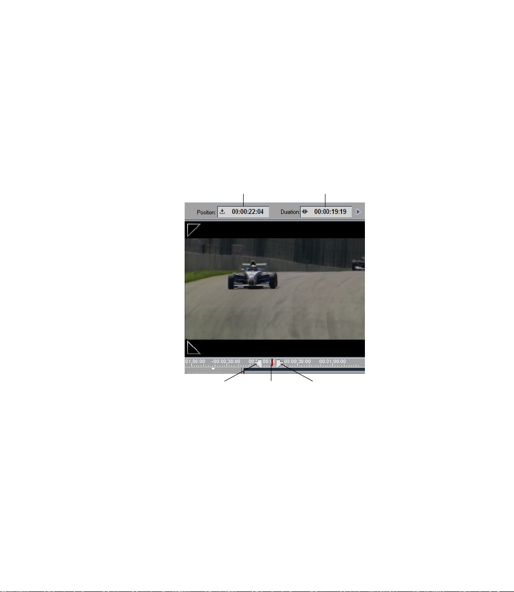
Chapter 3 Basics
Inlays
Inlay windows let you have a look at your video (moving or still), titles and graphics, effects to be rendered, etc. Even audio is displayed - as wave form.
Placed around the inlay windows you find all kinds of functions and displays. The example below (a
snapshot taken from the Clip Viewer) shows the position of the Playline and the duration of the clip
between the mark-in and mark-out points.
The inlays of Source and Master Viewers can be scaled to the size of the computer monitor. See “Fulls-
creen Display” on page 476 and “Inlay Quality Menu / Inlay Size” on page 479.
Position
Mark-In
Duration
Mark-OutPlayline
Sample inlay window (here shown with position bar
and two TC displays)
42
Page 71

Picons
Picon
Avid Liquid Desktop
The Avid Liquid desktop is the backdrop for all other elements of Avid Liquid, like Picons, for instance.
Three things can always be found on the desktop:
The Tr as h icon, the taskbar and the Project window.
Otherwise, the Avid Liquid desktop functions much like the Windows desktop (refer to the Windows
manual for further information).
Tour de Avid Liquid
All objects in Avid Liquid can also be displayed in Picon view. Picons
(picture icons) are still images that help you identify clips. Picon view
is ideal, for example, for developing a storyboard.
Picons are found on the Avid Liquid desktop, in the Project window,
on the Timeline and in numerous dialog boxes. For more information
on Picons, see “Picon View” on page 242 and “Picon Play” on
page 289.
The Taskbar
The taskbar appears at the bottom of the desktop.
Taskbar functions
Functions (from left):
Error/fps/drop frame Indicator
The “thumbs up” sign tells you that the system started correctly.
If a problem occurs, a flashing exclamation mark is displayed that is either yellow, orange or red, depending on the severity of the problem. Left-click the symbol to obtain detailed information on the current
problem.
Right-click the symbol to display a shortcut menu with the following options:
Show latest line of error log -
Opens a text box in the taskbar displaying the latest message.
43
Page 72

Chapter 3 Basics
Show error log -
Opens the list box with all the lines.
Reset error indicator -
Deletes all lines.
Show System Settings -
Displays general system settings (same as Edit > Control Panel > Site > System Settings).
Show current playback speed -
During Timeline playback, indicates the current number of frames per second (fps; stadard PAL:
25 fps, standard NTSC: 30 fps). Its main purpose is to allow you to check computer performance
for realtime software effects.
Show minimum playback speed -
Indicates the lowest fps value reached.
Reset speed indicator -
resets speed to default fps
Reset speed indicator always at start playback -
As soon as the Timeline is replayed, resets the last fps information identified.
Render Viewer
The icon (Σ, the Greek letter Sigma) represents the Render Viewer window. “Rendering” means the com-
putation of effects. Click the Σ icon to open the Render Viewer window, where you can monitor the ren-
dering process, and start and stop rendering. (See also “Effect Rendering” on page 536.)
The horizontal bar next to the window shows the rendering progress.
Provided that they contain clips with realtime effects, Slices (numeric segments of the Timeline) can be
rendered individually or in groups. This means that you can generally disable background rendering
(Render yellow slices) and then render specific segments. Right-click a Slice to open the shortcut menu
and select Force rendering for slice(s) [n] -> [m]. Hold down the
sequence of Slices (and thereby include Slices without effects at well; those will just be skipped).
SHIFT key while clicking to select a
44
Once the rendering process begins, the Sigma icon is replaced by a miniature of the image, provided you
have not disabled this function in the shortcut menu (right click). You can also use this menu to hide the
progress bar and stop the rendering process.
Key Caps
Click this icon to open the Key Caps window. For any software module, this window provides you with a
quick reference showing the functions assigned to the keys of the computer keyboard.
Refer to “Assign Functions to Keyboard” on page 993 for information on how you can change these
assignments.
Page 73

Tour de Avid Liquid
Select Video Output (LIVE Output)
Depending on the connected hardware (e.g.
video outputs here.
The option Liquid > IEEE 1394 activates output via the DV interface (useful if you have a TV monitor
connected to your camcorder).
Note that realtime effects can be previewed only via an analog output and in the Master Viewer’s video
inlay.
Avid Liquid PRO Box
), you can select various analog
Direct output of HD/HDV to an NTSC/PAL monitor, as well as to an HD monitor, is possible for
Avid Liquid Chrome HD
with a suitable breakout box (refer to the Product Manual).
If you own the
NTSC analog monitors. The scan rates of the video (25/50 or 30/60 Hz families) must match
those of the video monitor.
Activate this option in the System Settings by selecting Edit > Control Panel > Site > System Set-
tings > Inputs/Outputs > Video Outputs [analog] > HD Output = On.
Avid Liquid PRO Box
, you can output a downscaled HD image to PAL/
VGA Secondary Monitor routes video output to the secondary computer monitor (available only
with suitable dual-monitor graphics cards). See the readme for up-to-date information.
Audio Tool
Click this icon to open the Audio Tool, which you can use to control outgoing levels.
The adjacent rows of squares serve as an auxiliary level. The two uppermost segments in particular are
displayed in red to warn of an overload. For related information, refer to “Au di o Too l ” on page 806.
Digital or analog audio scrub: Right-click
two modes, then enable scrub by pressing the
indicates active scrub mode, and the type.
For further information on this subject see “Au d io S cr ubb ing - D ig i t al o r An al o g” on page 804.
on the icon to open a shortcut menu. Select either one of the
SCROLLLOCK key on your keyboard: In the icon an A or D
View Switcher
To access several views for the Avid Liquid interface, click the View Switcher (eye icon) and select an
available desktop view (“Click this icon to open a dialog box that can be used by members of a workgroup to
exchange information. When a message is received, this icon is replaced by a flashing reddish-orange telephone icon (page 197). Desktop Views” on page 46).
In a dual monitor setup, we suggest to select a desktop view that positions the Source and Master Viewers
on the left monitor (“primary”)
video.
: viewers on the right may cause dropped frames when playing back
45
Page 74

Chapter 3 Basics
InterCom
Click this icon to open a dialog box that can be used by members of a workgroup to exchange information. When a message is received, this icon is replaced by a flashing reddish-orange telephone icon
(page 197).
Desktop Views
The Avid Liquid desktop is able to display several windows at once, and you can configure them on the
desktop in different ways. The current configuration of windows visible on the desktop is called a “view.”
The View Switcher (eye icon) on the taskbar opens a shortcut menu that sets the current view on the VGA
monitor.
You can arrange icons such as those for the Tra s h and for Racks via the desktop shortcut menu.
Single VGA Mode
To change the arrangement of windows on the desktop:
1 Click the View Switcher icon at the right end of the taskbar to display the selection menu.
2 Click the particular view that you want.
You have now selected the view and the desktop is arranged accordingly.
or
46
1 Drag an object that you want to edit in another module to the View Switcher icon, keeping the
mouse button depressed. The selection menu is displayed.
2 Now drag the object to the particular view that you want and rest it on this view for a few
moments. The view changes and you can now continue working with the object.
Page 75

Views (One Monitor)
Tour de Avid Liquid
- Timeline only
- Sequence Editor above, Project window below
- Project window above, Timel ine below
- Project window only
- Sequence Editor above, Timeline below
- Single Monitor View (Project window, Source/Master Viewer and
Timeline)
The most common views are “Project window only” for developing Projects and “Project window above,
Time line below” or “Sequence Editor above, Timeline below” for the actual editing.
47
Page 76

Chapter 3 Basics
Using the Project Browser
The Project Browser proves especially useful when working on a single monitor system. When active, the
Project Browser takes up some space of the Timeline.
Rack/
folder area
Content area
Show/hide rack/
folder area
Views
Project shortcut menu
Project Browser
The Project Browser is a miniature Project window. Use the this tool button to call up the browser. If you
do not find the button on the Timelin e tool bar, retrieve it from the corresponding tool box (see “Custo-
mizing Toolbars” on page 990). To close the Project Browser, click the tool button again.
48
Change size and positions of browser -
The boundaries between Timeline and Project Browser as well as between content area and Rack/
Folder area can be moved. Place the mouse on the separating line and drag it to the desired posi-
tion (see arrows in screen shot above).
You may also change the positions of content area and Rack/Folder area. Right-click on the separating line between the areas and select a combination. Relative preserves the relative size of both
areas when dragging bigger or smaller.
To m ove th e Project Browser to, say, top of the Timeline, right-click the separating line between
browser and Timeline Headers and select an option from the shortcut menu.
Page 77

Tour de Avid Liquid
Show/Hide Rack Tree -
Click here to either show or hide the rack/folder area, depending on the current view.
Toggle tabs -
Click to toggle available Project tabs.
Switch Project -
In case you need material from a Project other than the current, it is possible to switch Projects.
The current Sequence remains on the Timelin e.
To do s o, r ig ht - cl i ck
worked on (same list as in the Open/Create Project submenu). Click the Project’s name to select it.
If you need a different Project, you will first have to open and close it the conventional way in
order to get it on the most recent list.
More information on “The Project Browser” on page 218.
the Show/Hide Rack Tree button. You get a list of the most recent Projects you
Dual VGA Mode
To change the arrangement of windows on the desktop:
1 Click the View Switcher icon at the right end of the taskbar to display the selection menu.
2 Click the particular view that you want.
You have now selected the view and the desktop is arranged accordingly.
In a dual monitor setup, we suggest to select a desktop view that positions the Source and Master Viewers
on the left or primary monitor: Viewers on the right may cause dropped frames when playing back video.
If you want Avid Liquid to span both monitors, the resolution of the monitors must be identical.
49
Page 78

Chapter 3 Basics
Views (Two Monitors)
- The Timelin e appears on both monitors
- The Project window appears on both monitors
- Left monitor: Sequence Editor above,
Project window below.
- Right monitor:
Timeline occupies entire monitor
- Left monitor: Sequence Editor above
- Right monitor: Project window above,
Timeline occupies bottom of both monitors
50
- Left monitor: Sequence Editor above,
Timeline below
- Right monitor:
Project window occupies entire monitor
- Left monitor:
Project window occupies entire monitor
- Right monitor:
Sequence Editor above, Timeline below
Page 79

Tour de Avid Liquid
Standard Windows Menu Bar
The menu bar is located along the top of the program window. You can use the usual Windows buttons in
the top right-hand corner to minimize or maximize the program window, but not to scale it to a particular size.
Most of the menu commands can also be accessed in other ways. For example, it is also possible
to open the Logging Tool for capturing video and audio by clicking a tool button or pressing a
function key. Other commands can be selected from the specific shortcut menus.
For some commands, you must first select a Rack or several clips in order to indicate where you
want to apply the function. For example, if you want to import a clip, first select the Rack to which
you want to import it.
You’ll notice that the background of certain windows starts to flash (light-gray – dark-gray). This
means that the subsequent action will be applied to this particular area. This is especially helpful
when, for instance, you have opened or selected multiple Racks.
Moreover, the contents of a menu can change depending on which area is currently activated.
Thus, for example, the Project menu is much shorter when you're working in the Project window
on the Library tab.
51
Page 80

Chapter 3 Basics
The Trash
To r emo ve ite ms f r om Racks, or shortcuts from the desktop, you can drag them to Tr a s h . The can
expands to indicate that there are items in it. The Tra s h tooltip, which appears when the mouse pointer
rests on the icon for more than one second, indicates the number of items in Tr a s h .
Right-click Tr a s h to access its shortcut menu.
Open -
opens a window that displays Tr a s h contents. You can drag items from the Tr a s h window to the
Project window to restore them. Dragging an item from the Tra s h window to the desktop creates a
shortcut to the item, but you cannot access the target object unless it also exists in the Project window.
52
Empty Trash -
removes the items in Tr a s h from the Project. Note that this does not delete the media, effect, etc.
files on the hard drive, it just removes them from the Project.
Clean Up Project -
The complete undo history of the current Project including all deleted objects will be erased. This
function should be used to minimize the size of a Project file, for example in the case of having
finished a program.
Delete Render Files Of Project -
See “Deleting Render Files” on page 347.
Diagnose Project -
see “Diagnose Project” on page 224
Paste -
puts the clipboard contents (an object you copied or cut from its original location) in Tr a s h . This
is the same as using the Tr a s h button or the Delete key, or selecting Delete in the shortcut menu.
Right-click in the Tr a s h window to select a Detail or Picon view of its contents.
Page 81

The Project Window
In this window, you can administer all the items needed for editing with Avid Liquid. The Project window displays all the elements for the currently open Project, including audio and video clips, effects,
graphics, etc. Similar in design and function to the Windows Explorer, the Project window uses a hierarchy of folders that you can customize to suit the Project and your own preferences.
The tree area on the left is used for creating and selecting folders and subfolders (called Racks). The content area on the right is used for organizing and viewing objects.
For more information on administration, see “The Project” on page 208.
Tour de Avid Liquid
Quick Finder
Rack/folder (tree) area
ToolsTabs
Project window
Rack menu icon
Content area
53
Page 82

Chapter 3 Basics
s
The Timeline
The Timel ine is the workspace in which you compile a film (in Avid Liquid known as Sequence) from the
individual objects in the Project. Objects are placed on Timeline Tra c k s . You can select the number and
size of the Tra c k s . Other elements used with the Ti melin e include the toolbar, Playline, Timecode Display
and Timecode Bar.
For more information on the Timeline and on editing video, see “Timeline Layout” on page 354.
Tracks
Timecode display Scroll bar
Zoom controller
ToolbarPlayline
Clips
Timecode bar
Timeline window
54
Page 83

The Sequence Editor
The Sequence Editor combines the Source Viewer, Master Viewer and the Timeline. The Source Viewer
(“player”) displays the clip that you want to edit. The Master Viewer (“recorder”) lets you play the
Sequence located on the Timeline.
For more information, see “Sequence Editor” on page 391.
Source Viewer
Tour de Avid Liquid
Sequence Editor
Master Viewer
Sequence Editor and Timeline
55
Page 84

Chapter 3 Basics
The Logging Tool
Before you can edit a video in Avid Liquid, the corresponding raw material must be available on your
computer or within in the network. The Logging Tool lets you transfer the video data to your hard disk
(mostly from a tape). Plus, you can control incoming audio and name clips.
For information on working with the Logging Tool, see the chapter “Input” on page 103.
56
Logging Too
Page 85

The Effect Editors
With the Effect Editors, you can create Transitions and clip effects (FX).
Tour de Avid Liquid
Tabs
Acceleration curve
Playline position
FX duration
Video inlayToolbar
Sample (Classic) Effect Editor
Toggl e i nc oming/
outgoing
Close
editor
ToolbarPosition bar
57
Page 86

Chapter 3 Basics
The Audio Editor
Most of the work that you do with audio material requires the Audio Editor. In the standard view, the
Audio Editor replaces the Source Viewer above the Timeline and starts with the Mixer tab in front. The
second tab contains Output Mapping. It allows you to mix audio signals in subgroups and distribute
them to the available outputs.
See “Aud io Ed it or ” on page 810.
Fader units
58
Audio Editor
Page 87

The Trim Editor
With the Tr i m E ditor, you can optimally coordinate movement in the image for editing purposes and
precisely trim transitions between individual cuts. The two inlays show you the frames before and after
the edit point. You can check the edit in Preview mode. The Slip Clip function allows you to trim the
mark-in and mark-out simultaneously.
See also “Trim Editor” on page 428.
Tour de Avid Liquid
Duration of outgoing clip
Outgoing clip
Edit point on the Timeline
Toolbar
TC +/- of trimmed clips
Select trim points
Duration of incoming clip
Incoming clip
Shortcut menu
59
Page 88

Chapter 3 Basics
60
Page 89

Chapter
Signup
4
Page 90

Chapter 4 Signup
You do not necessarily have to log on to Avid Liquid in order to work with the system, but doing so offers
certain advantages, especially when several users are working on the same system. If you log on under a
specific user name,
- The last Project edited under this name is opened with exactly the same status that it had when it was
last exited.
- The Avid Liquid user interface is configured with the customized settings for this user (toolbars, keyboard assignment, etc.).
- If applicable, you are prompted to enter a password that protects the settings against unauthorized
accesses.
All your individual settings (User Profile) can be saved on a diskette and used on any system running
under Avid Liquid, thus providing you with a portable, personalized working environment.
If the User Login dialog box does not appear on the system you are working on (because the software is
being launched for the first time or the dialog box was not used by previous users), exit Avid Liquid by
selecting File > Exit Avid Liquid >... log on as a different user. This will activate the login procedure.
If you do not need the User Log in dialog box, select Cancel or press
Logging on as an existing user page 63
New user/initial login page 64
Loading a user profile page 65
ESC to bypass it.
62
User Details page 66
Æ Comment page 66
Æ Password protection page 67
Removing a user page 68
Save user page 69
Page 91

Logging on As an Existing User
If other users are already registered on the system, the User Login dialog box will contain a list of names.
Select the appropriate name and click OK.
On initial installation of Avid Liquid in a directory where no previous installations exists, only one
Default User setting is being created instead of the usual six predefined User Settings you may know from
earlier versions (see figure). You can, however, save any existing User Settings on a disk and import them
into the new installation. Also, if Avid Liquid is installed on top of an older version, the old settings
remain accessible. In the case of a “true” initial installation, only the one Default User and three special
sets are created for users of Pinnacle Studio, Adobe Premiere and AVID editing programs:
For upgraders from Adobe Premiere and Pinnacle Studio
Users upgrading from Premiere or Studio to Avid Liquid can select special keyboard and toolbar assignments. Thus, the commands are available via the usual keys, and the software user interface offers a
reduced set of the most important commands.
Logging on As an Existing User
User Login
63
Page 92

Chapter 4 Signup
New User/Initial Login
1 In the User Log in dialog box, select New User to create a new user.
2 Then enter a name and select a user profile from the list; you can select either:
Default - Basic software setting
or
If any are present, another registered user or a sample user (basic, etc.) with his or her customized
settings. In other words, you can either work with the settings of another user or use these settings as a basis for defining your own settings.
3 Click OK.
64
New User/Load User Profile
Page 93

Load User Profile
If you have been working on a different Avid Liquid system, you can load your own individual settings
here.
In the dialog box, enter the source of this file (such as a diskette) and then open the file. The user name
appears in the list and you can now select it.
For information on saving User Profiles, refer to “Save User” on page 69.
Load User Profile
65
Page 94

Chapter 4 Signup
User Details
You can set up a new user by clicking User Details in either the User Login or New User dialog box. The
User Details dialog box lets you add or change the password and comments for a user.
Comments
This option is intended not so much for biographical information as for a description of the user profile;
you can configure your own aliases and optimize them for special applications (for example, “Audio
Use r”) .
User Details
66
Page 95

Passwords
Avid Liquid permits you to use a password to protect registered user settings against unauthorized
access.
Note that a password does not protect a Project against access; it protects a user profile. If you wish to
protect the overall system, use a Windows password (see the Windows manual).
Adding/Changing Passwords
In the Us er Detail s dialog box, click Password Protection to enable it. This opens the Change Password dialog box. Type the password in the New Password box, then type it again in the Confirm Password box.
Click OK to close the dialog box and assign the password to the user.
User Details
Change Password
Removing Passwords
In the User Details dialog box, a check mark in the Password Protection item indicates that the user name
is protected. To remove the password protection, click Password Protection. Avid Liquid prompts you to
enter the existing password to remove the protection.
67
Page 96

Chapter 4 Signup
Remove User
The User Selection box also lets you remove users. Select the user to be removed in the Registered Users
list, then click Remove User. If the user has password protection, enter the password to delete the user
name from the list. Avid Liquid prompts you to confirm before removing the user from the list.
68
Page 97

Save User
To save the settings of a specific user, use this function. For example, you can save the settings on floppy
disk so that you can use them on a different system; see also “Load User Profile” on page 65).
1 Select a User from the list and click this button. In the dialog box that appears...
2 ... specify where you want the data to be saved.
The following configurations are saved:
To o l b a r s
Object Properties dialog box settings
Property sets saved under Control Panel > User tab
Layout of software interface (desktop)
Project templates and Timeline templates cannot be saved together with a User Profile. However, with a
suitable storage medium, you can transfer Timeline and/or Project templates in the Avid Liquid folder,
from one system to another.
Save User
69
Page 98

Chapter 4 Signup
70
Page 99

Chapter
High Definition
5
Page 100

Chapter 5 High Definition
This chapter describes the HD capabilities of Avid Liquid.
Basics of high definition TV page 73
Better image, better sound: The TV of the future
High definition in Avid Liquid page 82
Æ HD-compatible products under Avid Liquid page 84
Æ HD workflow: Adapting settings page 83
Æ Timecode systems page 84
Æ Multiformat in Projects and on the Timeline page 85
Æ Quality ranks page 90
High definition at the input page 92
Æ HDV capture in the Logging Tool/EZ Capture page 92
Æ HDV batch capture page 94
Æ Capturing other MPEG2 video formats (MicroMV, D-VHS) page 94
Æ HD capture with
Æ Importing HD media files page 96
Avid Liquid Chrome HD
page 94
72
High definition on the timeline page 97
Æ Editing HD clips page 97
Æ HD and effects page 97
Æ HD monitoring page 98
Æ Combining SD and HD clips page 99
High definition at the output page 100
Æ Record to tape page 100
Æ Output as MPEG2 (tape and DVD) page 102
Æ Exporting to Windows Media HD page 102
In the field of HD and HDV, things are currently developing very rapidly. Due to its production cycles,
this manual is unable to react to all these developments. For the latest information, be sure to read the
ReadMe file that came with your software version.
 Loading...