

Page 1

LIGHTNING 1000
Installation Guide
Part No. 151000-INST Rev. B • January 1999
Page 2

Lightning 1000 Installation Guide
P/N 151000-INST • Rev. B • January1999 • Printed in U.S.A.
The information contained in this Installation Guide is subject to change
without notice or obligation.
Copyright
© 1999 PINNA CLE SYSTEMS, INC.
Contents of this publication may not be reproduced in any form without the
written permission of Pinnacle Systems, Inc. Reproduction or reverse
engineering of copyrighted software is prohibited.
Warning
Changes or modifications to this unit not expressly approved by the party
responsible for compliance could void the user’s authority to operate the
equipment.
FCC Compliance
This equipment has been tested and found to comply with the limits for a
Class A dig ital device, pursuant to Part 15 of the FCC Rules. These limits are
designed to provide reasonable protection against harmful interference when
the equipment is operated in a commercial en vironment. This equipment
generates, uses, and can radiate radio frequenc y energy and, if not installed
and used in accordance with the instruction manual, may cause harmful
interference to radio communications. Operation of this equipment in a
residential area is likely to cause harmful interference in which case the user
will be required to correct the interference at his own expense. Shielded
cables must be used to ensure compliance with the FCC Class A limits.
Lithium Battery Notice
German:
eingesetzt wird. Nur mit einem gleichen oder ähnlichen, vom Hersteller
empfohlenen Typ, ersetzen. Verbrauchte Batterien müssen per den
Instructionen des Herstellers verwertet werden.
English:
type. Replace only with the same type recommended by the manufacturer.
Dispose of used batteries according to the manufacturer’s instructions.
AcAc
htunghtung
Ac
AcAc
CACA
CA
CACA
. .
htung
. Explosionsgefahr wenn die Battery in umgekehrter Polarität
htunghtung
. .
UTION UTION
UTION - Danger of explosion if battery is replaced with incorrect
UTION UTION
Page 3

French:
AA
TTENTIONTTENTION
A
TTENTION. Il y a danger d’explosion s’il a remplacement incorrect
AA
TTENTIONTTENTION
de la batterie. Remplacer uniquement avec une batterie du meme type ou
d’un type equivalent recommande par le constructeur. Mettre au rebut les
batteries usagees conformement aux instructions du fabricant.
Power Supply Cord Notice
German:
Zur sicheren Trennung des Gerätes vom Netz ist der Netzstecker zu
ziehen. Vergewissern Sie sich, daß die Steckdose leicht zugänglich ist.
English:
CACA
UTIONUTION
CA
UTION:
CACA
UTIONUTION
DISCONNECT DEVICE, ENSURE THAT THE SOCKET-OUTLET IS
LOCATED/INSTALLED NEAR THE EQUIPMENT AND IS EASILY
ACCESSIBLE.
French:
AA
TTENTIONTTENTION
A
TTENTION: LE CORDON D’ALIMENTATION EST UTILISÉ
AA
TTENTIONTTENTION
COMME INTERRUPTEUR GÉNÉRAL. LA PRISE DE COURANT
DOIT ÊTRE SITUÉE OU INSTALLÉE À PROXIMITÉ DU MATÉRIEL
ET ÊTRE F ACILE D’ACCÉS.
THE POWER SUPPLY CORD IS USED AS THE MAIN
Company Address
Customer Service Fax (U.S.): (408) 933-8632
Customer Service Fax (Europe): +44 1895 442-009
Pinnacle Systems Inc.
280 North Bernardo Avenue
Mountain View, CA 94043
Customer Service (U.S.): (650) 930-2990
Customer Service (Europe): +44 1895 442-003
FaxBack: (650) 237-1973
Sales Literature: (800) 4 PINNACLE
Customer Support Internet: broadcast-support@pinnaclesys.com
Website: http://www.pinnaclesys.com
Page 4

Page 5

1: Introduction
Overview . . . . . . . . . . . . . . . . . . . . . . . . . . . . . . . . . . . . . . . . . . . . . . . . . . . . . . . . . 1
Documentation Conventions. . . . . . . . . . . . . . . . . . . . . . . . . . . . . . . . . . . . . . . . . . . 2
Primary Section . . . . . . . . . . . . . . . . . . . . . . . . . . . . . . . . . . . . . . . . . . . . . . . . . . . . 2
Secondary Section . . . . . . . . . . . . . . . . . . . . . . . . . . . . . . . . . . . . . . . . . . . . . . . . 2
Tertiary Section . . . . . . . . . . . . . . . . . . . . . . . . . . . . . . . . . . . . . . . . . . . . . . . . . . 2
Documentation Terms. . . . . . . . . . . . . . . . . . . . . . . . . . . . . . . . . . . . . . . . . . . . . . . . 3
Welcome to Lightning . . . . . . . . . . . . . . . . . . . . . . . . . . . . . . . . . . . . . . . . . . . . . . . . 4
Lightning Hardware . . . . . . . . . . . . . . . . . . . . . . . . . . . . . . . . . . . . . . . . . . . . . . . 4
Lightning Software . . . . . . . . . . . . . . . . . . . . . . . . . . . . . . . . . . . . . . . . . . . . . . . . 5
User Interface. . . . . . . . . . . . . . . . . . . . . . . . . . . . . . . . . . . . . . . . . . . . . . . . . . . . 5
Networking . . . . . . . . . . . . . . . . . . . . . . . . . . . . . . . . . . . . . . . . . . . . . . . . . . . . . . 5
Remote Control . . . . . . . . . . . . . . . . . . . . . . . . . . . . . . . . . . . . . . . . . . . . . . . . . . 6
System Inputs and Outputs . . . . . . . . . . . . . . . . . . . . . . . . . . . . . . . . . . . . . . . . . 6
A Word About Windows NT. . . . . . . . . . . . . . . . . . . . . . . . . . . . . . . . . . . . . . . . . . . . 6
TechFAX and Website. . . . . . . . . . . . . . . . . . . . . . . . . . . . . . . . . . . . . . . . . . . . . . . . 7
Related Publications . . . . . . . . . . . . . . . . . . . . . . . . . . . . . . . . . . . . . . . . . . . . . . . . . 7
Company Address and Phone Numbers. . . . . . . . . . . . . . . . . . . . . . . . . . . . . . . . . . 8
iii
Contents
2: Hardware Installation
In This Chapter . . . . . . . . . . . . . . . . . . . . . . . . . . . . . . . . . . . . . . . . . . . . . . . . . . . . . 9
What You Will Need. . . . . . . . . . . . . . . . . . . . . . . . . . . . . . . . . . . . . . . . . . . . . . . . . 10
Lightning Hardware. . . . . . . . . . . . . . . . . . . . . . . . . . . . . . . . . . . . . . . . . . . . . . . . . 11
Chassis Dimensions. . . . . . . . . . . . . . . . . . . . . . . . . . . . . . . . . . . . . . . . . . . . . . 11
Chassis Front Components . . . . . . . . . . . . . . . . . . . . . . . . . . . . . . . . . . . . . . . . 12
Chassis Rear Panel Components. . . . . . . . . . . . . . . . . . . . . . . . . . . . . . . . . . . . 13
Chassis Backplane Components . . . . . . . . . . . . . . . . . . . . . . . . . . . . . . . . . . . . 16
Chassis Internal Components . . . . . . . . . . . . . . . . . . . . . . . . . . . . . . . . . . . . . . 18
ShotBox Components. . . . . . . . . . . . . . . . . . . . . . . . . . . . . . . . . . . . . . . . . . . . . 21
Rear ShotBox Components . . . . . . . . . . . . . . . . . . . . . . . . . . . . . . . . . . . . . . . . 22
Setup Block Diagram . . . . . . . . . . . . . . . . . . . . . . . . . . . . . . . . . . . . . . . . . . . . . . . 23
Preparing Your Site . . . . . . . . . . . . . . . . . . . . . . . . . . . . . . . . . . . . . . . . . . . . . . . . . 24
Unpacking and Inspection. . . . . . . . . . . . . . . . . . . . . . . . . . . . . . . . . . . . . . . . . . . . 25
Installing Hardware . . . . . . . . . . . . . . . . . . . . . . . . . . . . . . . . . . . . . . . . . . . . . . . . . 25
Lightning 1000 Installation Guide
Page 6

iv
Connecting Signals. . . . . . . . . . . . . . . . . . . . . . . . . . . . . . . . . . . . . . . . . . . . . . . . . 25
Reference Connection . . . . . . . . . . . . . . . . . . . . . . . . . . . . . . . . . . . . . . . . . . . . 26
Input connection. . . . . . . . . . . . . . . . . . . . . . . . . . . . . . . . . . . . . . . . . . . . . . . . . 27
Output Connection . . . . . . . . . . . . . . . . . . . . . . . . . . . . . . . . . . . . . . . . . . . . . . . 27
Control and Network Connection . . . . . . . . . . . . . . . . . . . . . . . . . . . . . . . . . . . . 27
Display Connection. . . . . . . . . . . . . . . . . . . . . . . . . . . . . . . . . . . . . . . . . . . . . . . 28
Remote Control . . . . . . . . . . . . . . . . . . . . . . . . . . . . . . . . . . . . . . . . . . . . . . . . . 28
ShotBox Connection. . . . . . . . . . . . . . . . . . . . . . . . . . . . . . . . . . . . . . . . . . . . . . 29
GPI Connection . . . . . . . . . . . . . . . . . . . . . . . . . . . . . . . . . . . . . . . . . . . . . . . . . 29
Automation Systems Connections . . . . . . . . . . . . . . . . . . . . . . . . . . . . . . . . . . . 31
Power Connection . . . . . . . . . . . . . . . . . . . . . . . . . . . . . . . . . . . . . . . . . . . . . . . 31
Power Up Procedure. . . . . . . . . . . . . . . . . . . . . . . . . . . . . . . . . . . . . . . . . . . . . . . . 32
Power Down Procedure . . . . . . . . . . . . . . . . . . . . . . . . . . . . . . . . . . . . . . . . . . . . . 32
System Interconnect Diagram. . . . . . . . . . . . . . . . . . . . . . . . . . . . . . . . . . . . . . . . . 33
3: Software Installation
In This Chapter . . . . . . . . . . . . . . . . . . . . . . . . . . . . . . . . . . . . . . . . . . . . . . . . . . . . 35
Software Description. . . . . . . . . . . . . . . . . . . . . . . . . . . . . . . . . . . . . . . . . . . . . . . . 35
Installing Software . . . . . . . . . . . . . . . . . . . . . . . . . . . . . . . . . . . . . . . . . . . . . . . . . 36
System Files and User Files . . . . . . . . . . . . . . . . . . . . . . . . . . . . . . . . . . . . . . . . . . 36
Appendix A: Specifications ....................................................................... 37
Index.............................................................................................................39
Lightning 1000 Installation Guide
Page 7

1: Introduction
Overview
This guide provides installation instructions for Pinnacle’s Lightning
system. The following chapters are included:
1
Note
Tip
• Chapter 1,
hardware and software components of the Lightning system.
• Chapter 2,
for installing the system hardware.
• Chapter 3,
software updates or reinstalling the system software if required..
• Appendix A,
mechanical specifications.
An index is provided for your reference.
Refer to the Lightning ShotBox Tutorial and the Lightning Online Help
files for operating instructions.
Before installing your Lightning system, take a moment and fill out
your Lightning Registration Card—and be sure to send it in to Pinnacle
Systems. Registered Users will be informed of software updates and
release availability.
Introduction
Hardware Installation
Software Installation
Specifications
summarizes the guide and describes the
provides tables of electrical and
provides step-by-step directions
provides instructions for installing
Lightning 1000 Installation Guide
Page 8

2
Documentation Conventions
The following conventions are used throughout this guide:
• In the text, the first use of important terms are indicated in italic
letters. For example:
A
layout
is an image manipulation...
• In the text, references to material elsewhere within this manual are
also indicated in italic letters. For example:
Refer to the
• In an operations procedure, buttons are preceded by the word
Click the Freeze button to freeze...
• In the text, when two keyboard buttons must be pressed to perform
• Primary sections are listed in very large bold characters with a
Computer Requirements
“click.” For example:
a function, the “+” symbol is used between button names. This
symbol indicates that the first button is held down while the second
button is pressed. For example, the label
instructs you to hold down ALT and then press T. These combination functions are often called keyboard “accelerators.”
single line above:
section...
ALT + T
Primary Section
• Secondary sections are listed in large bold characters:
Secondary Section
• Tertiary sections are listed in bold italic characters:
Tertiary Section
Lightning 1000 Installation Guide
Page 9

Documentation T erms
The following terms are used throughout this guide:
•
•
•
•
•
•A
•A
•A
Operator and User
System
refers to the entire Lightning system itself.
Video System
(including switcher, edit controller and VTRs) in which the
Lightning is supported.
SDI
refers to Serial Digital Video, a digital signal that is distributed
via a single via a single coaxial cable with BNC connectors.
Image, Picture
pictures—created, touched-up or
Sequence
saved to the hard disk (with the .seq extension) and recalled later..
Source
refers to an input video signal (to a particular channel or
layer). Sources included external video inputs and key signals.
Channel
associated supporting key (2 inputs total), plus two outputs—video
and key. Lightning can have up to 3 channels, each with supporting key.
refers to represents a single video input with an
refer to the person who uses Lightning.
refers to the mix of interconnected equipment
and
Still
are used synonymously to describe still
captured.
is a playlist of stills (from 1 to 999). Sequences can be
3
•
Key
describes the effect of electronically cutting one image into
another.
Lightning 1000 Installation Guide
Page 10
4
Welcome to Lightning
Pinnacle’s Lightning is an advanced still store that allows you to record and
play stills, organize them into sequences, create transitions between
channels (from the “Preview” channel to the “Air” channel), and create
basic
layouts
third party plug-ins.
with your stills. You can also create your
own
transitions using
Note
Lightning
Channel 3
(optional)
For convenience and speed, the
Lightning Operator’s Manual
is
provided as an online help file instead of a printed document. Please
refer to the online manual for information on how to operate Lightning
with the keyboard and mouse. In addition, please refer to the
ShotBox Tutorial
for information on operating Lightning from the
Lightning
optional ShotBox.
The following sections briefly review Lightning’s features and functions.
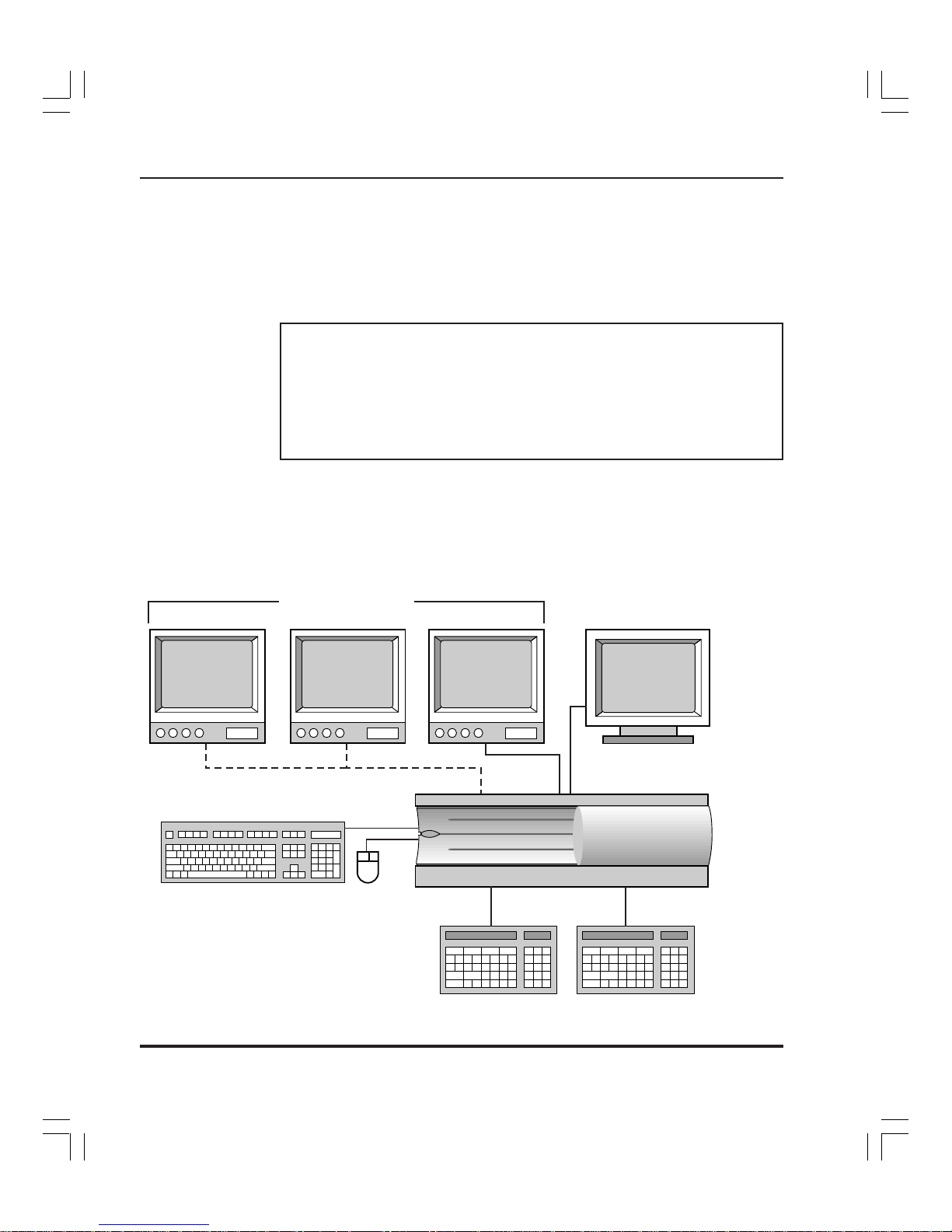
Lightning Hardware
The figure below illustrates a basic Lightning system. Optional equipment
is shown connected by dotted lines.
SDI Video Monitors
(customer supplied)
Lightning
Channel 2
(optional)
Lightning
Channel 1
SVGA
Monitor
(customer
Supplied)
Alphanumeric Keyboard
and Mouse
ShotBox A
(optional)
Lightning 1000 Installation Guide
Lightning
Chassis
ShotBox B
(optonal)
Page 11

The basic system consists of the Lightning electronics chassis (singlechannel), keyboard, and mouse. Two customer supplied components are
also required:
••
• An SVGA menu monitor for viewing the user interface (or
••
“display”)
• An SDI (serial digital) video monitor for previewing stills and
transitions
The following optional equipment can be added:
• Channel 2 and Channel 3 electronics
• Up to 2 ShotBoxes for remote control
The system is available in both 525 and 625 standards. See Chapter 2,
Hardware Installation
for details on Lightning’s system hardware.
Lightning Software
All Lightning software is provided on CD ROM for easy installation and
upgradeability. Each system also includes a 3.5" floppy disk drive (1.44
MB) for storing and transporting graphics, sequences, and layouts. Upon
power-up, the system boots, logs on to Windows NT, and automatically
launches the Lightning application for use with the User Interface or with
the ShotBox. See Chapter 3,
updating or reinstalling Lightning’s system software.
Software Installation
for complete details on
5
User Interface
All still record, play, sequence and layout functions are performed with
Lightning’s SVGA display (in combination with the mouse and keyboard),
or with the dedicated ShotBox. All ShotBox buttons are arranged in concise
groups according to functionality. The primary ShotBox function buttons
have built-in LEDs for additional user-feedback.
The SVGA menu display is divided into sections or windows, each of
which serves a different Lightning function. Windows are reserved for the
image database, for layout parameters, and for creating sequences of stills.
Networking
Each Lightning system includes a standard network card. This card allows
you to connect Lightning to your facility’s network with the ability to share
stills and sequences across multiple platforms.
Refer to your
Lightning as a network node.
Windows NT User’s Guide
Lightning 1000 Installation Guide
for details on configuring your
Page 12

6
Remote Control
The Lightning system can be controlled remotely via GPI, RS-422 automation or OLE commands.
System Inputs and Outputs
A Lightning system can be configured with a maximum of three CCIR-601
Input/Output channels as shown below:
Inputs
Video
Key
Video
Key
Video
Key
Lightning
Chassis
Note that each channel has
(4:2:2 on the video input connector; 4:0:0 on the key input connector).
Refer to Chapter 2,
A Word About Windows NT
Channel
1
Channel
2
Channel
one input
which is 4:2:2:4—video plus key
Hardware Installation
Outputs
Video Out
Key Out
Video Out
Key Out
Video Out
3
for complete I/O details.
Key Out
The Lightning system runs in the Windows™ NT environment. This guide
assumes that you are comfortable with standard Windows-based procedures, such as using Dialog Boxes. These procedures will not be discussed
in this guide. If you are not familiar with Windows NT, refer to your
Windows NT User’s Guide
subject.
or to one of the many third-party books on the
Lightning 1000 Installation Guide
Page 13

TechFAX and Website
As a vital part of our ongoing customer support activities, Pinnacle Systems
offers several important services:
• FaxBack and TechFAX
7
A FaxBack system is online and available for 24-hour technical
support information. The system provides up-to-the-minute
Lightning information, technical tips, troubleshooting procedures
and important application notes. All TechFAX documents are
updated on a regular basis.
• Website
For optimum performance with Pinnacle’s Website, two programs are
Note
recommended: Netscape Navigator version 4.0 (or later), or Internet
Explorer version 3.0 (or later).
Related Publications
Use the following references for additional information:
• Refer to the
••
• Refer to the
••
To utilize the service, you
highly recommended that your initial request is the TechFAX
catalog, document number 1. Then, follow the instructions to
receive additional TechFAX documents.
FaxBack (U.S.): (650) 237-1973
Pinnacle System’s Website offers valuable and timely information
about the company, its full range of products, and detailed information about customer service. The Website also lists all
TechFAXes and pertinent application notes.
Pinnacle’ s Website address is listed below.
http://www .pinnaclesys.com
Lightning ShotBox Tutorial
on Lightning operations, using the optional ShotBox.
Lightning Online Help Files
additional operating instructions using the keyboard and mouse.
must
dial in from your fax machine. It is
for an introductory course
for reference material and
Lightning 1000 Installation Guide
Page 14

8
Company Address and Phone Numbers
Pinnacle Systems Inc.
280 North Bernardo Avenue
Mountain View, California 94043 USA
• Customer Service (U.S.): (650) 930-2990
• Customer Service (Europe): +44 1895 442-003
• Customer Service Fax (U.S.): (408) 933-8632
• Customer Service Fax (Europe): +44 1895 442-009
• FaxBack: (650) 237-1973
• Sales Literature: (800) 4 PINNACLE
• Customer Support Internet: broadcast-support@pinnaclesys.com
• Website: http://www.pinnaclesys.com
Lightning 1000 Installation Guide
Page 15

2: Hardware Installation
In This Chapter
This chapter provides a hardware description, plus comprehensive instructions for installing your Lightning hardware. The following major sections
are included.
• What Y ou Will Need
• Lightning Hardware
• Setup Block Diagram
• Preparing Y our Site
• Unpacking and Inspection
• Installing Hardware
• Connecting Signals
9
Important
• Power Up Procedure
• Power Down Procedure
• System Interconnect Diagrams
When performing the following installation procedure, always observe
these important safety and handling precautions.
• Follow anti-static precautions.
• If you need to handle the internal chassis mechanism, ground
yourself to the chassis first.
• If you need to handle the internal boards, hold the boards from the
edges—do not touch the chips.
Lightning 1000 Installation Guide
Page 16

10
What Y ou Will Need
The Lightning system consists of the following required components.
Pinnacle-supplied:
Customer-supplied:
Optional Equipment:
• Lightning electronics chassis (single-channel standard)
• Lightning software operating system
• Mouse
• Alphanumeric keyboard
• SVGA menu monitor
• Analog composite reference video signal (Black)
• Component Digital (SDI) video output monitoring
• Component Digital (SDI) sources
• Component Digital (SDI) devices (e.g., switchers, recorders).
• A stable power source
• Additional channels (systems supports up to two channels)
• Lightning dedicated ShotBox (up to two can be connected)
• 25-foot (7.6 m) ShotBox Cable(s)
• ShotBox Power Supply (up to two)
For rack mounting, you will require 7 inches (178 mm) of vertical rack
space (4 RU). If possible, provide 1 RU (Rack Unit) of space above the unit.
To provide optimum air flow, do not obstruct the front air passage or block
the rear fan vents.
Lightning 1000 Installation Guide
Page 17

Lightning Hardware
The following topics are covered in this section:
Chassis Dimensions
The Lightning Chassis is 7.0 inches (178 mm) or 4 rack units high, 17.0
inches (432 mm) wide and 24.5 inches (622 mm) deep.
11
• Chassis Dimensions
• Chassis Front Components
• Chassis Rear Panel Components
• Chassis Backplane Components
• Chassis Internal Components
• ShotBox Components
• Rear ShotBox Components
24.5"
7.0"
17.0"
The Chassis is designed for rack-mounting in a standard equipment rack.
All video and control connections are located on the rear of the Chassis.
Refer to the
Signal Connection
Lightning 1000 Installation Guide
section for input/output connection details.
Page 18

12
Chassis Front Components
The figure below illustrates the front of the Lightning chassis.
21 3
4765
1) Power Switch 4) Power LED 7) Floppy Disk
2) Air Vents 5) Disk Drive LED
3) Door 6) CD ROM
With door closed
With door open
1. Power Switch. Press to turn Lightning on and off.
2. Air Vents. Lightning’s internal components and power supply are
cooled by multiple fans. Air flows through the front vents to the
internal fans. To provide optimum air flow, do not obstruct the
front air vents.
3. Door. The front door slides to reveal the floppy drive and CD
ROM.
4. Power LED. The green Power LED lights when the system is on.
5. Disk Drive LED. The yellow Disk Drive LED lights when there is
hard drive activity.
6. CD ROM. The CD ROM Drive is provided for loading and
updating software.
7. Floppy Disk. A standard 3.5" Floppy Disk Drive (1.44 MB) is
provided for offline storage of graphics, transitions, sequences and
layouts.
Lightning 1000 Installation Guide
Page 19

Chassis Rear Panel Components
The figure below illustrates the rear panel of the Lightning chassis (Serial
Digital version).
13
43 5 119
MENU OUTPUTS
Y/C
SVGA
COMPOSITE
K/B SCSI
MOUSE
NETWORK
RS422-A
RS422-C
GPI-A
REF-LOOP
12 13 20 2114 15 16 1817 19
1) Captive Screws 8) Channel 2 I/O 15) Network
2) Air Vents 9) Digital Video Output 16) Keyboard
3) Y/C Video Menu Output 10) Channel 1 I/O 17) Not Used
4) Composite Video Menu Output 11) Digital Key Output 18) Reference Loop
5) SVGA Menu Output 12) Rear Connector Panel 19) GPI Ports
6) RS-422 Ports 13) AC Power In 20) A/Video Input
7) Channel 3 I/O 14) Mouse 21) B/Key Input
DIGITAL I/O
OUTPUT
RS422-B
VIDEO KEY
RS422-D
INPUT
GPI-B
A / VIDEO B / KEY A / VIDEO B / KEY
DIGITAL I/O DIGITAL I/O
OUTPUT OUTPUT
VIDEO KEY VIDEO KEY
INPUT INPUT
A / VIDEO B / KEY
11 2 7 8 106
1. Captive Scre ws. Two captive screws secure the Rear Connector
Panel to the chassis. Releasing them allows the hinged panel to
drop down.
2. Air Vents. Lightning’s internal components and power supply are
cooled by multiple fans. Air flows through the front vents to the
internal fans, and out through these rear chassis exhaust vents. To
provide optimum air flow, do not obstruct the front and rear vents.
3. Y/C Video Menu Output. One Y/C connector is provided for the
menu output in Y/C video format. Use this connector (and a
customer-supplied Y/C monitor) when you wish to monitor the
user interface in Y/C format (typically at distances greater than five
meters from the chassis).
4. Composite Video Menu Output. One BNC connector is provided
for the menu output in composite video format. Use this connector
(and a customer-supplied composite monitor) when you wish to
Lightning 1000 Installation Guide
Page 20

14
monitor the user interface in composite format (typically at
distances greater than five meters from the chassis).
5. SVGA Menu Output. One 15-pin “D” connector is provided for
the system’s SVGA display menu output. Use this menu output for
the maximum video quality. The Y/C and Composite outputs are
only available at resolutions less than 800 x 600.
Note
The SVGA output provides a much higher quality output than the Y/C
output or Composite output. Use the SVGA output whenever possible.
6. RS-422 Ports. Four 9-pin “D” connectors are provided for connecting Lightning to control devices and automation control. RS-422A and RS-422-B are designed for connection to optional ShotBox
controllers. RS-422-C and RS-422-D connectors are provided for
connecting Lightning to automation systems for control.
7. Channel 3 Input/Output. This capability is optional on a Lightning
system. Two CCIR-601 inputs (Video and Key) and two CCIR-601
outputs (Video and Key) are provided with the option. If the
channel is not installed, a blank panel is provided.
8. Channel 2 Input/Output. This capability is optional on a Lightning
system. Two CCIR-601 inputs (Video and Key) and two CCIR-601
outputs (Video and Key) are provided with the option. If the
channel is not installed, a blank panel is provided.
9. Digital Video Output*. One BNC connector is provided on each
installed Channel for a CCIR-601 Digital Video Output. Connect
the output to the video input of a destination CCIR-601 device
such as a digital video routing switcher or monitor.
10. Channel 1 Input/Output. Channel 1 Input/Output capability is
standard on a Lightning system. Two CCIR-601 inputs (Video and
Key) and two CCIR-601 outputs (Video and Key) are provided.
11. Digital Key Output*. For all installed channels, one BNC connector is provided for a CCIR-601 Digital Key Output. Connect the
output to the key input of a destination CCIR-601 device such as a
digital video routing switcher.
12. Rear Connector Panel. The Rear Connector Panel is hinged at the
bottom. It drops down to provide access to internal connectors on
the backplane.
13. AC Power In. The AC Line cord connects here to provide chassis
power.
Lightning 1000 Installation Guide
Page 21

15
14. Mouse. One 5-pin “PS2” connector is provided for the Mouse.
15. Network. One RJ-45 connector is provided for connecting Light-
ning to your facility’s PC network. Either a 10-baseT or 100-baseT
connection can be used. The Network card is standard. Refer to
your Windows NT User’s Guide for details on configuring Lightning as a network node.
16. Keyboard. One 5-pin “PS2” connector is provided for the alphanu-
meric keyboard.
17. Not Used.
18. Reference Loop. Two BNC connectors are provided for an analog
reference video signal (and a reference loop if required). Refer to
the “Reference Connection” section for instructions.
19. GPI Ports. Two 15-pin “D” connectors are provided for GPI as
input connections. GPI-A is used to connect GPI lines from an
automation system. These lines allow the automation system to
trigger a variety of Lightning functions. GPI-B is currently not
implemented. See the Remote Control section for details on GPI
connections and pinouts.
20. Digital Video Input*. For all installed channels, one BNC connec-
tor is provided for a CCIR-601 Digital Video Input. The input is a
4:2:2 connection. Refer to Chapter 4,
Setup
for instructions.
Note
21. Digital Key Input*. For all installed channels, one BNC connector
is provided for a CCIR-601 Digital Key Input. The input is a 4:0:0
connection. Refer to Chapter 4,
* These connector explanations apply to all input/output cards in your
specific system (Channel 1, Channel 2 and Channel 3).
If your SVGA monitor or your mouse need to be located more than 15
feet (5 m) away from the chassis, any standard extender system can be
added.
Lightning 1000 Installation Guide
Setup
for details.
Page 22

16
Chassis Backplane Components
When the two captive screws on the rear panel are released, the Rear
Connector Panel drops down to reveal the Backplane. The figure below
illustrates the backplane and the associated connectors on the rear of
Lightning’s internal cards.
1 2 3 4 5 6 7 8 9 10 11 12
13 16 1714
15 18
1) Air Vents 7) Blank Slot 13) Power
2) Blank Slot 8) Blank Slot 14) Keyboard
3) SVGA Card 9) Blank Slot 15) Mouse
4) Network Card 10) Blank Slot 16) Com 2
5) DVE Card 11) Ch. 2 Digital I/O Card (opt) 17) Com 1
6) RS-422 Card 12) Ch. 1 Digital I/O Card (std) 18) Parallel Port
1. Air Vents. This set of exhaust vents are located immediately behind
the CPU fan and hard drives. Air flows through the front vents to
the internal fans, and out through these vents. Do not obstruct the
front and rear vents.
2. Blank Slot.
3. SVGA Card. The SVGA Card generates menu output video and
SVGA signals. Three connectors are provided:
a. Composite. One RCA jack interconnects to the rear panel
a
Composite Video Menu Output connector. This output
functions only at resolutions less than 800 x 600.
b
b. Y/C. One Y/C jack interconnects to the rear panel Y/C Video
Menu Output connector. This output functions only at
c
resolutions less than 800 x 600.
c. SVGA. One 15-pin “D” jack interconnects to the rear panel
SVGA Menu Output connector.
Lightning 1000 Installation Guide
Page 23

17
4. Network Card. One RJ-45 jack interconnects to the rear panel
Network connector.
5. DVE Card. The standard DVE card provides the electronics for
Lightning’s layout, GPI, and remote control capabilities. Two 5Pin “D” connectors are provided. Use the upper connector only.
6. RS-422 Card. This multi-port serial board connects to the four RS-
422 connectors on the rear panel of the chassis via ribbon cables.
7 – 9. Blank Slots.
10. Channel 3 Digital I/O Card (optional). The Channel 3 Digital I/O
card (optional) provides the electronics for the second channel’s
digital video and key inputs and outputs. Five connectors are
provided. See below for details.
11. Channel 2 Digital I/O Card (optional). The Channel 2 Digital I/O
card (optional) provides the electronics for the second channel’s
digital video and key inputs and outputs. Five connectors are
provided. See below for details.
12. Channel 1 Digital I/O Card (standard). The Channel 1 Digital I/O
card (standard) provides the electronics for the first channel’s
digital video and key inputs and outputs.
Note that the connectors descriptions listed below apply to all three
Digital I/O Cards:
a. Key Out. One mini-BNC jack connects to the rear panel Key
a
Out connector for the selected channel.
b. Video Out. One mini-BNC jack connects to the rear panel
b
c
Video Out connector for the selected channel.
c. Key In. One mini-BNC jack connects to the rear panel Key In
connector for the selected channel.
d
e
d. Video Out. One mini-BNC jack connects to the rear panel
Video Out connector for the selected channel.
e. Refer ence. For one channel only, one mini-BNC jack connects
to the rear panel Reference In and Reference Loop connectors.
This jack is only connected on Channel 1’s card and is not
used on Channels 2 and 3.
13. Power. The power cable (from the internal power supply) is routed
through this hole to the rear AC connector panel.
14. Keyboard. One 5-pin “PS2” jack interconnects to the rear panel
Keyboard connector.
15. Mouse. One 5-pin “PS2” jack interconnects to the rear panel
Mouse connector.
16. Com 2 (RS-232). This 9-pin connector is an industry-standard RS-
232 port.
Lightning 1000 Installation Guide
Page 24

18
17. Com 1. This 9-pin connector is an industry-standard RS232 port.
18. Parallel Port. This 25-pin connector is used for the Lightning
security dongle. However, it can also be used to connect a printer.
Chassis Internal Components
The figure below illustrates a top view of the interior of the Lightning
chassis, with the top cover plate removed.
Front of Chassis
7
1
2 3
4 5 6
22 23
11 1716 1812 1413 15
98 10
19
20
21
Rear of Chassis
Lightning 1000 Installation Guide
Page 25

1) Motherboard and CPU 9) SVGA Card 17) Ch. 2 I/O Card (opt.)
2) CD ROM Drive 10) Network Card 18) Ch. 1 I/O Card (std.)
3) Floppy Disk Drive 11) DVE Card 19) Video Connector Board
4) CPU Fan Assembly 12) RS-422 Card 20) Control Connector Board
5) Standard Hard Drive 13) Blank Slot 21) Input Matrix Board
6) Ventilation Holes 14) Blank Slot 22) Rear Connector Panel
7) Power Supply & Fan Assembly 15) Blank Slot 23) Backplane Connector Panel
8) SCSI Card 16) Ch. 3 I/O Card (opt.)
Additional information is listed below, for selected items only.
1. Motherboard and CPU. The Motherboard and CPU provide the
electronics for the Windows NT platform and Lightning’s effects
computing power.
2. CD ROM Drive. The CD ROM Drive is provided for loading and
updating software.
3. Floppy Disk Drive. A standard 3.5" Floppy Disk Drive (1.44 MB)
is provided for offline storage of graphics, transitions, sequences
and layouts.
4. CPU Fan Assembly. The CPU Fan Assembly provides cooling for
the Motherboard and CPU underneath.
19
5. Standard Hard Drive. The standard Hard Drive provides storage
for the Lightning program, stills, transitions, sequences, and
layouts.
6. Ventilation Holes. These holes allow for cooling of the CPU and
Hard Drive
7. Power Supply and Dual Fan Assembly. The Power Supply provides
all required voltages. The Dual Fan Assembly cools the power
supply and additional interior components.
8. SCSI Card. The SCSI Card provides the electronics for the
system’s ultra wide SCSI capability.
9. SVGA Card. The SVGA Card generates menu output video and
SVGA signals.
10. Network Card. The Network Card provides the electronics for
connecting Lightning to a PC network.
11. DVE Card. The DVE Card provides the electronics for Lightning’s
GPI, remote control, and “layouts” capabilities.
12. RS-422 Card. This multi-port serial board provides four RS-422
ports for connection to optional Shotbaxes and automation
systems.Blank Slot.
13. Blank Slot
Lightning 1000 Installation Guide
Page 26

20
14. Blank Slot.
15. Blank Slot.
16. Channel 3 Digital I/O Card (optional). The Channel 3 Digital I/O
Card provides the electronics for the optional third channel’s
digital video and key inputs and outputs.
17. Channel 2 Digital I/O Card (optional). The Channel 2 Digital I/O
Card provides the electronics for the optional second channel’s
digital video and key inputs and outputs.
18. Channel 1 Digital I/O Card. The Channel 1 Digital I/O Card
provides the electronics for the first channel’s digital video and key
inputs and outputs.
19. Video Connector Board. The Video Connector Board carries video
signals to and from the individual channels to the DVE board.
20. Control Connector Board. The Control Connector Board allows the
DVE board to control the individual channel boards.
21. Input Matrix Board. The Input Matrix Board interconnects the
three channel boards, and provides a routing matrix for video
signals.
22. Rear Connector Panel.
23. Backplane Connector Panel.
Lightning 1000 Installation Guide
Page 27

ShotBox Components
The figure below illustrates ShotBox components.
1 2
PINNACLE
F1 F2 F3 F4
EFX/
MENUS STILLS SEQ
LAYOUT
PVW
FRAME KEY RECORD
MODE
MEMORY
MEMORY
RECALL
ENTER
789
21
CANCEL R1 R2 R3 R4 R5 R6 FREEZE
PLAY A PLAY B
TAKE
PLAY C
DISPLAY
MODE
SHIFT
INS
DEL
456
123
CLEAR ENTER
0
43
1) Status Display 3) Function Group
2) Keypad Display 4) Keypad
1. Status Display . The Status Display shows information such as still
names, sequences, and messages.
2. Keypad Display. The Keypad Display shows numeric entries in
progress, and provides information about transitions, durations,
and layouts.
3. Function Group. The Function Group includes buttons that activate
all of the ShotBox’s primary features, such as recording, playback,
and sequence creation. Typically, pressing a button calls up
information on the Status Display.
4. Keypad. The Keypad includes buttons for entering numbers and
layouts.
Lightning 1000 Installation Guide
Page 28

22
Rear ShotBox Components
The figure below illustrates the rear components of the Lightning ShotBox.
1 2
1) Power Connector 2) Control Connector
1. Control Connector. One 9-pin “D” Control Connector is provided
for connecting the ShotBox to the Lightning Chassis. The ShotBox
can be placed at a maximum distance of 500 meters (1,640 feet)
from the chassis. One 25-foot (7.6 m) cable is supplied.
2. Power Connector. One miniature connector is provided for
connecting the Universal Power Supply to the ShotBox.
Note
Refer to the Lightning ShotBox Tutorial and the Lightning On-Line
Help files for system operating instructions.
Lightning 1000 Installation Guide
Page 29

Setup Block Diagram
For reference in the following procedures, a simplified system block
diagram of a Digital system is provided below. Lightning chassis connector
names are listed inside the Lightning chassis block.
Video Inputs
Digital
Input Sources
Digital
Input Sources
Digital
Input Sources
Reference
House Reference
(75 ohm Terminator
or Loop)
Power
AC Power
Control
Mouse
Keyboard
PC Network
(10-baseT or 100-baseT)
Power
AC Power
Digital
Video
Key
Digital
Video
Key
Digital
Video
Key
In
Out
AC In
Mouse
Keyboard
Network
Lightning
Chassis
Channel 1
(standard)
Channel 2
(optional)
Channel 3
(optional)
Digital
Video
Key
Digital
Video
Key
Digital
Video
Key
SVGA
Y/C
Comp
RS422-A
RS422-B
RS422-C
RS422-D
GPI-A
GPI-B
SCSI
Video Outputs
To Monitor, Routing Switcher
To Routing Switcher
To Monitor, Routing Switcher
To Routing Switcher
To Monitor, Routing Switcher
To Routing Switcher
Display
To SVGA Monitor
T o Y/C Video Monitor
To Composite Video Monitor
RS422
To ShotBox A
To ShotBox B
To Automation system
To Automation system
GPI
To Automation system
(Not Implemented)
SCSI
To SCSI Devices
23
AC Power
Universal
Power Supply
DC Power
Universal
Power Supply
DC Power
ShotBox B
Power
Power
(optional)
ShotBox A
(optional)
Lightning 1000 Installation Guide
RS422
Control
Control
Page 30

24
Preparing Y our Site
When preparing to install your Lightning system, attention should be given
to Environmental, Power and Location requirements.
System voltage (NTSC and PAL) . . . . . . 110/220V auto-sensing, 50/60 Hz
Power consumption . . . . . . . . . . . . . . . . . <500 Watts
The following table lists power requirements for the Lightning ShotBox.
Note that power is supplied from a separate supply.
• Environmental Requirements
Lightning is designed to operate in normal “machine room” or
“control room” conditions. Care must also be taken to avoid
temperature and humidity extremes.
• Location and Power Requirements
The following table lists power r equirements for the Lightning Chassis.
Lightning Chassis PLightning Chassis P
Lightning Chassis P
Lightning Chassis PLightning Chassis P
oo
ww
er Requirer Requir
o
w
er Requir
oo
ww
er Requirer Requir
ementsements
ements
ementsements
P a r ameter Specification
Lightning ShotBoLightning ShotBo
Lightning ShotBo
Lightning ShotBoLightning ShotBo
x Px P
x P
x Px P
oo
ww
er Requirer Requir
o
w
er Requir
oo
ww
er Requirer Requir
ementsements
ements
ementsements
Parameter Specification
System voltage (NTSC and PAL) . . . . . . 110/220V auto-sensing, 50/60 Hz
Power consumption . . . . . . . . . . . . . . . . . <50 Watts
When connecting Lightning, take care to avoid power lines that are
subject to noise and voltage spikes. Do not install the system on a power
circuit that is common to such equipment as air conditioners and refrigeration units. An AC noise filter and surge protector are recommended if
unstable power conditions are present.
Lightning 1000 Installation Guide
Page 31

Unpacking and Inspection
When you receive your Lightning system, inspect the shipping cartons for
signs of physical damage. Contact your dealer and the shipper immediately
if you suspect any damage has occurred during shipping. Check the
contents of each box to be sure that all parts are included. If any items are
missing, contact your dealer immediately. After unpacking all equipment,
please save the packing materials for future shipping convenience.
Installing Hardware
Install the Lightning chassis in an equipment rack with adequate room and
ventilation. Use the supplied rack rails and mounting hardware.
Note that Lightning requires 7.0 inches of vertical space (4RU). If possible,
provide 1 RU (rack unit) of space above the Lightning chassis.
• Do not obstruct the front air vents or block the rear fan. This
will ensure optimum air flow and maximum chassis cooling.
25
Note
Connecting Signals
This section provides step-by-step instructions for connecting video,
control, power, and communication signals.
Note
If your hardware is not already rack-mounted, refer to the
Hardware
Connect all required signals as outlined in the following sections.
• Provide a sufficient service loop for all rear chassis power and
video cables. Keep in mind that the rear chassis panel is
hinged, and drops down to reveal the backplane and associated
internal connectors.
• Refer to the
illustration of all rear chassis connectors.
• Refer to the
illustration of all backplane connectors.
section for details.
Chassis Rear Panel Components
Chassis Backplane Components
section for an
section for an
Installing
Lightning 1000 Installation Guide
Page 32

26
Reference Connection
To connect video reference:
1. Connect a stable analog reference signal (such as Black Burst)
from your house sync generator to the left-hand Reference
connector.
Note
The house sync generator must feed the same reference to all devices in
your Lightning system.
2. If Lightning is the last device in your reference loop, terminate the
right-hand Reference connector with a 75-ohm terminator as
shown below.
Reference Out
Loop
Loop
75 Ohm
Terminator
Sync Generator
VTR 1
VTR 2
Lightning
3. If Lightning is in the middle of your reference loop, connect the righthand Reference connector to the next device’s reference input connector, as
shown below
Reference Out
Sync Generator
Loop
Loop
Loop
to next
device
Lightning 1000 Installation Guide
VTR 1
Lightning
VTR 2
Page 33

Note
27
Input connection
To connect digital video inputs:
1. Connect CCIR-601 digital video sources to the A/Video Input
connector on all standard and optional channels in your system.
2. Connect CCIR-601 digital key sources to the B/Key Input connec-
tor on all standard and optional channels in your system.
Output Connection
To connect digital video outputs:
1. For all standard and optional channels in your system, connect the
Video Output connector to the desired destination input (typically,
a video monitor or a routing switcher).
2. For all standard and optional channels, connect the Key Output to
the desired destination input (typically, a routing switcher).
The user can redefine channel assignments via software. In this
condition, note that your system’s physical wiring and logical channel
assignments may not match.
Control and Network Connection
To connect control and network connections:
1. Connect the supplied mouse to the Mouse connector.
2. Connect the supplied alphanumeric keyboard to the Keyboard
connector.
3. Plug an RJ-45 connector (from a designated network transceiver)
into the Network port, to connect Lightning to your facility’s PC
network. The network card accepts both 10-baseT and 100-baseT
connections. Refer to your Windows NT User’s Guide for details
on configuring Lightning as a network node.
Lightning 1000 Installation Guide
Page 34

28
Note
Display Connection
To connect menu monitor display outputs:
1. Connect a customer-supplied SVGA monitor to the SVGA
connector, for all “local” menu display monitoring requirements
(in conjunction with the local alphanumeric keyboard).
2. Connect a customer-supplied composite monitor to the Composite
connector, for remote menu display monitoring in the composite
format (as required by your system configuration).
3. Connect a customer-supplied Y/C monitor to the Y/C connector,
for remote menu display monitoring in the Y/C format.
• The SVGA connection is the preferred one for maximum
video quality.
• The Composite and Y/C connections are less than ideal, and
should be used only when absolutely necessary. These outputs
are only available at resolutions less than 800 x 600.
Remote Control
The Lightning systems allow a variety of functions to be controlled externally from three different classes of controllers: the Lightning Shotbox, GPI
Triggers and RS-422 control via the Lightning Automation Protocol. This
section includes information on connecting these control options to your
Lightning 1000 system.
Lightning 1000 Installation Guide
Page 35

ShotBox Connection
To connect the optional ShotBox A and ShotBox B:
1. Connect the supplied 25-foot (7.6 m) RS-422 cable (supplied with
the option) from the chassis RS422-A port to the Control port on
ShotBox A. The configuration of port RS422-A is COM3.
2. Connect the supplied 25-foot (7.6 m) RS-422 cable (supplied with
the option) from the chassis RS422-B port to the Control port on
ShotBox B. The configuration of port RS422-B is COM4.
The following table provides pinout information for the RS-422-A and RS-
difdif
ff
erer
422-B connectors (mini 9-pin “D” Female). Note that these are
from the pinouts of ports RS-422-C and RS-422-D.
12345
6789
Pin Signal Pin Signal
1 No connection 6 Power Ground
2 Transmit – 7 Transmit +
3 Receive + 8 Receive –
4 Power Ground 9 Chassis Ground
5 Chassis Ground
dif
difdif
entent
f
er
ent
ff
erer
entent
29
GPI Connection
GPI (General Purpose Interface) is a method by which electronic “pulses”
from one device are used to trigger functions on another device.
This section provides instructions for connecting GPI inputs for four
assignable GPI inputs. When an external device such as an automation
system is connected and when remote control is enabled (using the Enable
GPI triggers menu item), external pulses can control specific functions of
the Lightning.
See your automation system’s manual for steps on connecting its GPI lines.
The following table lists GPI input specifications.
Parameter Specification
Minimum Pulse Width. . . . . . . .5 mS
Action . . . . . . . . . . . . . . . . . . . Pull-down to ground
Current sourcing . . . . . . . . . . . Approximately 5 mA
Lightning 1000 Installation Guide
Page 36

30
To connect GPI input lines, you will need to build a custom cable that
connects the automation system’s GPI output to the desired input ports on
the Lightning’s GPI connector. The figure below illustrates a typical GPI
interface circuit.
+ GPI
Automation System’s
Relay Output
Pin 1 (in 0) Pin 11 (in 1)
Pin 3 (in 2)
Ground
Pins 2, 4, 6, 12, 14
Pin 13 (in 3)
Lightning
GPI Inputs
Simplified Schematic of GPI Interface
The following table provides pinout information for the GPI Connector
(mini 15-pin “D” Male).
1 2 3 4
6 7 8 9
5
10
15
14
12 13
11
Pin Signal Pin Signal
1 In 0 9 Out 1 +
2 Ground 10 Out 1 –
3 In 2 11 In 1
4 Ground 12 Ground
5 No connection 13 In 3
6 Ground 14 Ground
7 Out 0 + 15 No connection
8 Out 0 –
Lightning 1000 Installation Guide
Page 37

Automation Systems Connections
Ports RS-422-C and RS-422-D are designed to connect the Lightning 1000
to automation systems that can control it via Lightning’s RS-422 protocol.
The configuration of port RS422-C is COM5, and port RS-422-D is
configured as COM6. The following table provides pinout information for
difdif
ff
erer
the connectors (mini 9-pin “D” Female). Note that these are
the pinouts of ports RS-422-A and RS-422-B.
dif
difdif
entent
f
er
ent
from
ff
erer
entent
31
12345
6789
Pin Signal Pin Signal
1 No connection 6 Power Ground
2 Receive – 7 Receive +
3 Transmit + 8 Transmit –
4 Power Ground 9 Chassis Ground
5 Chassis Ground
Power Connection
A stable power source must be provided to all devices in your system. As a
precaution, spread the load evenly and don’t overload any one circuit
breaker. Avoid power lines that are subject to noise and voltage spikes.
To connect Chassis power, connect AC power to the AC In connector on the
Lightning rear chassis panel.
To connect ShotBox power:
1. Connect AC power to the AC Input connector on the Universal
Power Supply.
2. Connect the Universal Power Supply’s miniature connector to the
Power connector on the ShotBox.
Lightning 1000 Installation Guide
Page 38

32
Power Up Procedure
To power up the Lightning system:
1. Ensure that all peripheral equipment is powered on, including the
SVGA monitor and the ShotBox.
2. Press the Power switch on the front of the Lightning chassis. The
green Power LED (below the switch) lights when the system is on.
At this point, the system boots up and launches the Lightning
application.
Power Down Procedure
To power down the Lightning system:
1. Exit from the Lightning application by pressing the standard
Windows “close” box in the upper right corner of the window.
2. Click Start on the Windows NT Taskbar.
3. Click Shut Down... to display the Shut Down dialog box.
4. Select the “Shut down the computer” radio button.
5. Click Yes. The system writes unsaved data to disk, then displays
the Shutdown Computer dialog box.
6. Press the Power switch on the front of the Lightning chassis to shut
down the system.
Lightning 1000 Installation Guide
Page 39

System Interconnect Diagram
The diagram below shows an example of video, control and reference
connections. All devices shown are CCIR-601 digital video format.
33
Reference
Signal
Loop
Loop
Loop
Sync Generator
Facility Sources
Video and Key
VTR 2
Graphics System
Local Control
SVGA
Monitor
Keyboard
Camera
VTR
To Facility
Destination Devices
Video
Monitor(s)
Ch.1 In Video
Ch.1 In Key
Ch. 2 In Video
Ch. 2 In Key
Channel
Production Switcher
Large or Small-scale
Facility Routing
Switcher
1
Channel
2
ShotBox Control
ShotBox B ShotBox A
Lightning
Loop
75 Ohm Terminator
Video out Ch.1
Video out Ch. 2
Key out Ch.1
Key out Ch. 2
In this example, note that the output of the Lightning system feeds a facility
routing switcher, for subsequent distribution to all desired facility destinations
such as graphics systems, production switchers, VTRs, and transmission.
Lightning 1000 Installation Guide
Page 40

34
Lightning 1000 Installation Guide
Page 41

3: Software Installation
In This Chapter
This chapter provides instructions for installing and updating Lightning
software. The following sections are included.
• Software Description
• Installing Software
• System Files and User Files
Software Description
The Lightning system runs in the Windows(tm) NT environment, and all
operating system software must be installed prior to Lightning installation.
Additionally, NT installation must include Microsoft Service Pack 2 for NT
or higher for proper operation. The NT installation must also include
networking software, regardless of whether the system is actually used in a
network.
35
The software is product-specific, and will only operate in conjunction with
the Lightning board set.
Lightning 1000 Installation Guide
Page 42

36
Installing Software
All Lightning software is provided on CD ROM. Software installation is
only required upon initial system installation, when you receive updated
Lightning software from Pinnacle, or in the event of a system fault that
prevents the software from loading properly.
To install Lightning software, please refer to the Lightning Release
Important
Notes for complete instructions. These notes are provided in printed
form and also in electronic form (on the supplied CD ROM). The
filename for the release notes is ReadMe.Doc.
System Files and User Files
On the Lightning hard disk, several directories and sub-directories are
added for important “system” files and “user” files. These directories are
factory-configured and revised as required when the system software is
updated or re-installed.
Important
As a precaution, Lightning’s system directories and files should not be
moved, renamed or otherwise deleted from your hard disk.
When using Lightning during normal operations, you are free to create
your own directories and sub-directories for storage of “user” files. These
files can contain stills, transitions, layouts and sequences as desired.
Lightning 1000 Installation Guide
Page 43

Appendix A: Specifications
In This Appendix
The following section is provided in this Appendix:
• Specifications
Specifications
This section provides Lightning technical specifications.
System Format
• NTSC: 525/60Hz
• PAL: 625/50Hz
System Inputs
Each channel has the following I/O’s:
37
• Digital I/O module
– One CCIR-601 serial digital input with separate digital key
input.
– One CCIR-601 serial digital output with separate serial digital
key output.
External Reference Loop-through
• 1V peak-to-peak analog black burst or composite video high
impedance loop through.
System Chassis Control Interface
• (2) RS-422 serial 9-pin “D” female, for ShotBox interconnect
(DCE)
• (2) RS-422 serial 9-pin “D” female, for automation interconnect
(DTE)
• GPI 15-pin “D”.
Chassis Dimensions
• Inches: 17.0 (W) x 24.5 (D) x 7.0 (H)
• Centimeters: 43.18 (W) x 62.23 (D) x 17.78 (H)
Lightning 1000 Installation Guide
Page 44

38
Lightning 1000 Installation Guide
Page 45

Index
39
Symbols
10-baseT, 100-baseT 15
525 and 625 standards 5
A
AC Power In 14
air vents 12
analog reference signal 26
Automation Protocol, Lightning 28
Automation Systems Connections 31
B
Black Burst 26
C
CCIR-601 6
CD ROM 5, 12, 19, 36
Channel 3
Channel Input/Output 14
channel output 6
Chassis dimensions 37
chassis dimensions 11
COM ports 17, 29, 31
components, customer supplied 5
Composite connector 28
Composite Video menu output 13
Connections, ShotBox 22
connector ports 13
Control connection 27
Control Connector Board 20
Control Interface 37
cooling requirements 12
Customer service 7
customer supplied components 5, 10
D
Diagram, system interconnection 33
Digital I/O Card 17, 20
Digital I/O module 37
Digital Key Input 15
Digital Key Output 14
Digital Video Input 15
Digital Video Output 14
DVE Card 17, 19
E
Expansion slots 19
External Reference 37
F
FaxBack 7
file directories 36
Floppy Disk drive 12, 19
front door 12
Function Group, ShotBox 21
G
GPI remote control 6
GPI Connection 29
GPI Interface 30
GPI Ports 15
GPI Triggers 28
H
Hard Drive 19
Hardware, installing 25
Hardware, Lightning 500 11
I
Input channels 6
Input connection 27
Input Matrix Board 20
Installing Software 36
Internet Explorer 7
K
Keyboard 15
Keypad Displa y, ShotBox 21
Lightning 1000 Installation Guide
Page 46

40
L
S
LEDs 12
Lightning Hardware 4
Lightning Automation Protocol 28
M
menu monitor display 28
Motherboard 19
Mouse 15
N
Netscape Navigator 7
Network Card 19
Network connection 5, 27
O
Optional Equipment 5, 10
Output channels 6
Output Connection 27
outputs from Lightning 13
P
Parallel P ort 18
Pinnacle-supplied hardware 10
pinouts of RS-422 ports 29, 31
Po wer Up & Do wn Procedure 32
Po wer Requirements 24
Po wer Supply 19
SDI 3
SDI video monitor 5
Sequence 3
Setup Block Diagram 23
ShotBox 21
ShotBox connections 29
Signals, connecting 25
Site Preparation 24
Software Description 35
Software installation 5
Specifications 37
Status Display, ShotBox 21
SVGA Card 16, 19
SVGA connector 28
SVGA menu output 14
SVGA monitor 5
sync generator 26
system vs. user files 36
T
TechFAX 7
Technical support 7
terminator, when required 26
U
Unpacking and Inspection 25
User Interface 5
user vs. system files 36
R
rack-mounting 11
Reference Loop 15
Related Publications 7
Release Notes 36
Remote Control 6, 28
RJ-45 connector 15, 27
RS-422 6
RS-422 Card 17
RS-422 control 28
RS-422 ports 14
V
Video Connector Board 20
Video System 3
W
Website 7
Windows NT 6
www .pinnaclesys .com 7
Y
Y/C connector 28
Y/C Video menu output 13
Lightning 1000 Installation Guide
 Loading...