

Page 1

Avid® ISIS® 7000
Setup Guide
Page 2

Legal Notices
Product specifications are subject to change without notice and do not represent a commitment on the part of Avid Technology,
Inc.
This product is subject to the terms and conditions of a software license agreement provided with the software. The product
may only be used in accordance with the license agreement.
Avid ISIS products or portions thereof are protected by one or more of the following United States Patents: 6,374,336;
6,415,373; 6,449,688; 6,760,808; 6,785,768; 7,111,115; 7,487,309; 7,660,947. Other patents are pending.
Avid products or portions thereof are protected by one or more of the following European Patents: 1040419.
Other patents are pending.
Part of the software embedded in this product is gSOAP software.
Portions created by gSOAP are Copyright (C) 2001-2004 Robert A. van Engelen, Genivia inc. All Rights Reserved.
THE SOFTWARE IN THIS PRODUCT WAS IN PART PROVIDED BY GENIVIA INC AND ANY EXPRESS OR IMPLIED
WARRANTIES, INCLUDING, BUT NOT LIMITED TO, THE IMPLIED WARRANTIES OF MERCHANTABILITY AND FITNESS
FOR A PARTICULAR PURPOSE ARE DISCLAIMED. IN NO EVENT SHALL THE AUTHOR BE LIABLE FOR ANY DIRECT,
INDIRECT, INCIDENTAL, SPECIAL, EXEMPLARY, OR CONSEQUENTIAL DAMAGES (INCLUDING, BUT NOT LIMITED TO,
PROCUREMENT OF SUBSTITUTE GOODS OR SERVICES; LOSS OF USE, DATA, OR PROFITS; OR BUSINESS
INTERRUPTION) HOWEVER CAUSED AND ON ANY THEORY OF LIABILITY, WHETHER IN CONTRACT, STRICT
LIABILITY, OR TORT (INCLUDING NEGLIGENCE OR OTHERWISE) ARISING IN ANY WAY OUT OF THE USE OF THIS
SOFTWARE, EVEN IF ADVISED OF THE POSSIBILITY OF SUCH DAMAGE.
This document is protected under copyright law. An authorized licensee of Avid ISIS 7000 may reproduce this publication for
the licensee’s own use in learning how to use the software. This document may not be reproduced or distributed, in whole or in
part, for commercial purposes, such as selling copies of this document or providing support or educational services to others.
This document is supplied as a guide for Avid ISIS 7000. Reasonable care has been taken in preparing the information it
contains. However, this document may contain omissions, technical inaccuracies, or typographical errors. Avid Technology,
Inc. does not accept responsibility of any kind for customers’ losses due to the use of this document. Product specifications
are subject to change without notice.
Copyright © 2010 Avid Technology, Inc. and its licensors. All rights reserved.
The following disclaimer is required by Sam Leffler and Silicon Graphics, Inc. for the use of their TIFF library:
Copyright © 1988–1997 Sam Leffler
Copyright © 1991–1997 Silicon Graphics, Inc.
Permission to use, copy, modify, distribute, and sell this software [i.e., the TIFF library] and its documentation for any purpose
is hereby granted without fee, provided that (i) the above copyright notices and this permission notice appear in all copies of
the software and related documentation, and (ii) the names of Sam Leffler and Silicon Graphics may not be used in any
advertising or publicity relating to the software without the specific, prior written permission of Sam Leffler and Silicon
Graphics.
THE SOFTWARE IS PROVIDED “AS-IS” AND WITHOUT WARRANTY OF ANY KIND, EXPRESS, IMPLIED OR
OTHERWISE, INCLUDING WITHOUT LIMITATION, ANY WARRANTY OF MERCHANTABILITY OR FITNESS FOR A
PARTICULAR PURPOSE.
IN NO EVENT SHALL SAM LEFFLER OR SILICON GRAPHICS BE LIABLE FOR ANY SPECIAL, INCIDENTAL, INDIRECT
OR CONSEQUENTIAL DAMAGES OF ANY KIND, OR ANY DAMAGES WHATSOEVER RESULTING FROM LOSS OF USE,
DATA OR PROFITS, WHETHER OR NOT ADVISED OF THE POSSIBILITY OF DAMAGE, AND ON ANY THEORY OF
LIABILITY, ARISING OUT OF OR IN CONNECTION WITH THE USE OR PERFORMANCE OF THIS SOFTWARE.
The following disclaimer is required by the Independent JPEG Group:
This software is based in part on the work of the Independent JPEG Group.
This Software may contain components licensed under the following conditions:
Copyright (c) 1989 The Regents of the University of California. All rights reserved.
Redistribution and use in source and binary forms are permitted provided that the above copyright notice and this paragraph
are duplicated in all such forms and that any documentation, advertising materials, and other materials related to such
distribution and use acknowledge that the software was developed by the University of California, Berkeley. The name of the
University may not be used to endorse or promote products derived from this software without specific prior written
permission. THIS SOFTWARE IS PROVIDED ``AS IS'' AND WITHOUT ANY EXPRESS OR IMPLIED WARRANTIES,
INCLUDING, WITHOUT LIMITATION, THE IMPLIED WARRANTIES OF MERCHANTABILITY AND FITNESS FOR A
PARTICULAR PURPOSE.
2
Page 3

Copyright (C) 1989, 1991 by Jef Poskanzer.
Permission to use, copy, modify, and distribute this software and its documentation for any purpose and without fee is hereby
granted, provided that the above copyright notice appear in all copies and that both that copyright notice and this permission
notice appear in supporting documentation. This software is provided "as is" without express or implied warranty.
Copyright 1995, Trinity College Computing Center. Written by David Chappell.
Permission to use, copy, modify, and distribute this software and its documentation for any purpose and without fee is hereby
granted, provided that the above copyright notice appear in all copies and that both that copyright notice and this permission
notice appear in supporting documentation. This software is provided "as is" without express or implied warranty.
Copyright 1996 Daniel Dardailler.
Permission to use, copy, modify, distribute, and sell this software for any purpose is hereby granted without fee, provided that
the above copyright notice appear in all copies and that both that copyright notice and this permission notice appear in
supporting documentation, and that the name of Daniel Dardailler not be used in advertising or publicity pertaining to
distribution of the software without specific, written prior permission. Daniel Dardailler makes no representations about the
suitability of this software for any purpose. It is provided "as is" without express or implied warranty.
Modifications Copyright 1999 Matt Koss, under the same license as above.
Copyright (c) 1991 by AT&T.
Permission to use, copy, modify, and distribute this software for any purpose without fee is hereby granted, provided that this
entire notice is included in all copies of any software which is or includes a copy or modification of this software and in all
copies of the supporting documentation for such software.
THIS SOFTWARE IS BEING PROVIDED "AS IS", WITHOUT ANY EXPRESS OR IMPLIED WARRANTY. IN PARTICULAR,
NEITHER THE AUTHOR NOR AT&T MAKES ANY REPRESENTATION OR WARRANTY OF ANY KIND CONCERNING THE
MERCHANTABILITY OF THIS SOFTWARE OR ITS FITNESS FOR ANY PARTICULAR PURPOSE.
This product includes software developed by the University of California, Berkeley and its contributors.
The following disclaimer is required by Paradigm Matrix:
Portions of this software licensed from Paradigm Matrix.
The following disclaimer is required by Ray Sauers Associates, Inc.:
“Install-It” is licensed from Ray Sauers Associates, Inc. End-User is prohibited from taking any action to derive a source code
equivalent of “Install-It,” including by reverse assembly or reverse compilation, Ray Sauers Associates, Inc. shall in no event be
liable for any damages resulting from reseller’s failure to perform reseller’s obligation; or any damages arising from use or
operation of reseller’s products or the software; or any other damages, including but not limited to, incidental, direct, indirect,
special or consequential Damages including lost profits, or damages resulting from loss of use or inability to use reseller’s
products or the software for any reason including copyright or patent infringement, or lost data, even if Ray Sauers Associates
has been advised, knew or should have known of the possibility of such damages.
The following disclaimer is required by Videomedia, Inc.:
“Videomedia, Inc. makes no warranties whatsoever, either express or implied, regarding this product, including warranties with
respect to its merchantability or its fitness for any particular purpose.”
“This software contains V-LAN ver. 3.0 Command Protocols which communicate with V-LAN ver. 3.0 products developed by
Videomedia, Inc. and V-LAN ver. 3.0 compatible products developed by third parties under license from Videomedia, Inc. Use
of this software will allow “frame accurate” editing control of applicable videotape recorder decks, videodisc recorders/players
and the like.”
The following disclaimer is required by Altura Software, Inc. for the use of its Mac2Win software and Sample
Source Code:
©1993–1998 Altura Software, Inc.
The following disclaimer is required by Interplay Entertainment Corp.:
The “Interplay” name is used with the permission of Interplay Entertainment Corp., which bears no responsibility for Avid
products.
This product includes portions of the Alloy Look & Feel software from Incors GmbH.
This product includes software developed by the Apache Software Foundation (http://www.apache.org/).
3
Page 4

© DevelopMentor
This product may include the JCifs library, for which the following notice applies:
JCifs © Copyright 2004, The JCIFS Project, is licensed under LGPL (http://jcifs.samba.org/). See the LGPL.txt file in the Third
Party Software directory on the installation CD.
Avid Interplay contains components licensed from LavanTech. These components may only be used as part of and in
connection with Avid Interplay.
Attn. Government User(s). Restricted Rights Legend
U.S. GOVERNMENT RESTRICTED RIGHTS. This Software and its documentation are “commercial computer software” or
“commercial computer software documentation.” In the event that such Software or documentation is acquired by or on behalf
of a unit or agency of the U.S. Government, all rights with respect to this Software and documentation are subject to the terms
of the License Agreement, pursuant to FAR §12.212(a) and/or DFARS §227.7202-1(a), as applicable.
Trademarks
003, 192 Digital I/O, 192 I/O, 96 I/O, 96i I/O, Adrenaline, AirSpeed, ALEX, Alienbrain, AME, AniMatte, Archive, Archive II,
Assistant Station, AudioPages, AudioStation, AutoLoop, AutoSync, Avid, Avid Active, Avid Advanced Response, Avid DNA,
Avid DNxcel, Avid DNxHD, Avid DS Assist Station, Avid Liquid, Avid Media Engine, Avid Media Processor, Avid MEDIArray,
Avid Mojo, Avid Remote Response, Avid Unity, Avid Unity ISIS, Avid VideoRAID, AvidRAID, AvidShare, AVIDstripe, AVX,
Axiom, Beat Detective, Beauty Without The Bandwidth, Beyond Reality, BF Essentials, Bomb Factory, Boom, Bruno, C|24,
CaptureManager, ChromaCurve, ChromaWheel, Cineractive Engine, Cineractive Player, Cineractive Viewer, Color Conductor,
Command|24, Command|8, Conectiv, Control|24, Cosmonaut Voice, CountDown, d2, d3, DAE, Dazzle,
Dazzle Digital Video Creator, D-Command, D-Control, Deko, DekoCast, D-Fi, D-fx, Digi 003, DigiBase, DigiDelivery,
Digidesign, Digidesign Audio Engine, Digidesign Development Partners, Digidesign Intelligent Noise Reduction,
Digidesign TDM Bus, DigiLink, DigiMeter, DigiPanner, DigiProNet, DigiRack, DigiSerial, DigiSnake, DigiSystem,
Digital Choreography, Digital Nonlinear Accelerator, DigiTest, DigiTranslator, DigiWear, DINR, DNxchange, DPP-1, D-Show,
DSP Manager, DS-StorageCalc, DV Toolkit, DVD Complete, D-Verb, Eleven, EM, EveryPhase, Expander, ExpertRender,
Fader Pack, Fairchild, Fastbreak, Fast Track, Film Cutter, FilmScribe, Flexevent, FluidMotion, Frame Chase, FXDeko,
HD Core, HD Process, HDPack, Home-to-Hollywood, HYBRID, HyperControl, HyperSPACE, HyperSPACE HDCAM,
iKnowledge, Image Independence, Impact, Improv, iNEWS, iNEWS Assign, iNEWS ControlAir, Instantwrite, Instinct,
Intelligent Content Management, Intelligent Digital Actor Technology, IntelliRender, Intelli-Sat,
Intelli-sat Broadcasting Recording Manager, InterFX, Interplay, inTONE, Intraframe, iS Expander, ISIS, IsoSync, iS9, iS18,
iS23, iS36, ISIS, IsoSync, KeyRig, KeyStudio, LaunchPad, LeaderPlus, LFX, Lightning, Link & Sync, ListSync, LKT-200, Lo-Fi,
Luna, MachineControl, Magic Mask, Make Anything Hollywood, make manage move | media, Marquee, MassivePack,
Massive Pack Pro, M-Audio, M-Audio Micro, Maxim, Mbox, Media Composer, MediaDock, MediaDock Shuttle, MediaFlow,
MediaLog, MediaMatch, MediaMix, Media Reader, Media Recorder, MEDIArray, MediaServer, MediaShare, MetaFuze,
MetaSync, MicroTrack, MIDI I/O, Midiman, Mix Rack, MixLab, Moviebox, Moviestar, MultiShell, NaturalMatch, NewsCutter,
NewsView, Nitris, NL3D, NLP, Nova, NRV-10 interFX, NSDOS, NSWIN, Octane, OMF, OMF Interchange, OMM, OnDVD,
Open Media Framework, Open Media Management, Ozone, Ozonic, Painterly Effects, Palladium, Personal Q, PET, Pinnacle,
Pinnacle DistanTV, Pinnacle GenieBox, Pinnacle HomeMusic, Pinnacle MediaSuite, Pinnacle Mobile Media,
Pinnacle Scorefitter, Pinnacle Studio, Pinnacle Studio MovieBoard, Pinnacle Systems, Pinnacle VideoSpin, Podcast Factory,
PowerSwap, PRE, ProControl, ProEncode, Profiler, Pro Tools|HD, Pro Tools LE, Pro Tools M-Powered, Pro Transfer, Pro Tools,
QuickPunch, QuietDrive, Realtime Motion Synthesis, Recti-Fi, Reel Tape Delay, Reel Tape Flanger, Reel Tape Saturation,
Reprise, Res Rocket Surfer, Reso, RetroLoop, Reverb One, ReVibe, Revolution, rS9, rS18, RTAS, Salesview, Sci-Fi, Scorch,
Scorefitter, ScriptSync, SecureProductionEnvironment, Serv|LT, Serv|GT, Session, Shape-to-Shape, ShuttleCase, Sibelius,
SIDON, SimulPlay, SimulRecord, Slightly Rude Compressor, Smack!, Soft SampleCell, Soft-Clip Limiter, Solaris,
SoundReplacer, SPACE, SPACEShift, SpectraGraph, SpectraMatte, SteadyGlide, Streamfactory, Streamgenie, StreamRAID,
Strike, Structure, Studiophile, SubCap, Sundance Digital, Sundance, SurroundScope, Symphony, SYNC HD, Synchronic,
SynchroScope, SYNC I/O, Syntax, TDM FlexCable, TechFlix, Tel-Ray, Thunder, Titansync, Titan, TL Aggro, TL AutoPan,
TL Drum Rehab, TL Everyphase, TL Fauxlder, TL In Tune, TL MasterMeter, TL Metro, TL Space, TL Utilities,
tools for storytellers, Torq, Torq Xponent, Transfuser, Transit, TransJammer, Trigger Finger, Trillium Lane Labs, TruTouch,
UnityRAID, Vari-Fi, Velvet, Video the Web Way, VideoRAID, VideoSPACE, VideoSpin, VTEM, Work-N-Play, Xdeck, X-Form,
Xmon, XPAND!, Xponent, X-Session, and X-Session Pro are either registered trademarks or trademarks of Avid Technology,
Inc. in the United States and/or other countries.
Apple, Macintosh, and Safari are either registered trademarks or trademarks of Apple Computer, Inc., registered in the U.S.
and other countries. HP is a registered trademark of Hewlett-Packard Company. Intel is a registered trademark of Intel
Corporation. Java is a trademark of Sun Microsystems in the United States and/or other countries. Kingston is a registered
trademarks of Kingston Technology Corporation. All other marks may be the property of their respective titleholders. Windows
is either a registered trademark or trademark of Microsoft Corporation in the United States and/or other countries. All other
trademarks contained herein are the property of their respective owners.
Avid ISIS 7000 Setup Guide •0130-30227-01 Rev. B• July 2010 • Created 7/30/10
4
Page 5

Contents
Symbols and Conventions . . . . . . . . . . . . . . . . . . . . . . . . . . . . . . . . . . . . . . . . . . . . 11
If You Need Help. . . . . . . . . . . . . . . . . . . . . . . . . . . . . . . . . . . . . . . . . . . . . . . . . . . . 12
Accessing the Online Documentation . . . . . . . . . . . . . . . . . . . . . . . . . . . . . . . . . . . . 13
Avid Training Services . . . . . . . . . . . . . . . . . . . . . . . . . . . . . . . . . . . . . . . . . . . . . . . 13
Software Upgrade . . . . . . . . . . . . . . . . . . . . . . . . . . . . . . . . . . . . . . . . . . . . . . . . . . . 15
Hardware Upgrade . . . . . . . . . . . . . . . . . . . . . . . . . . . . . . . . . . . . . . . . . . . . . . . . . . 17
New System Director and Engine Installation. . . . . . . . . . . . . . . . . . . . . . . . . . . . . . 18
Switch and ISB Upgrade Utility . . . . . . . . . . . . . . . . . . . . . . . . . . . . . . . . . . . . . . . . . 19
Recreating a File Systems . . . . . . . . . . . . . . . . . . . . . . . . . . . . . . . . . . . . . . . . . . . . 20
Chapter 1 Avid ISIS 7000 System Overview . . . . . . . . . . . . . . . . . . . . . . . . . . . . . . . 21
Hardware Overview and Naming Convention. . . . . . . . . . . . . . . . . . . . . . . . . . . . . . 21
System Director. . . . . . . . . . . . . . . . . . . . . . . . . . . . . . . . . . . . . . . . . . . . . . . . . . . . . 24
System Director Front Panel . . . . . . . . . . . . . . . . . . . . . . . . . . . . . . . . . . . . . . . 25
System Director Rear Connections . . . . . . . . . . . . . . . . . . . . . . . . . . . . . . . . . . 26
Second System Director. . . . . . . . . . . . . . . . . . . . . . . . . . . . . . . . . . . . . . . . . . . 26
Engine. . . . . . . . . . . . . . . . . . . . . . . . . . . . . . . . . . . . . . . . . . . . . . . . . . . . . . . . . . . . 27
Engine Front View . . . . . . . . . . . . . . . . . . . . . . . . . . . . . . . . . . . . . . . . . . . . . . . 27
Engine Rear View. . . . . . . . . . . . . . . . . . . . . . . . . . . . . . . . . . . . . . . . . . . . . . . . 28
Power Supplies . . . . . . . . . . . . . . . . . . . . . . . . . . . . . . . . . . . . . . . . . . . . . . . . . 28
Integrated Ethernet Switches . . . . . . . . . . . . . . . . . . . . . . . . . . . . . . . . . . . . . . . 29
Storage Configurations. . . . . . . . . . . . . . . . . . . . . . . . . . . . . . . . . . . . . . . . . . . . 30
Storage Group Size . . . . . . . . . . . . . . . . . . . . . . . . . . . . . . . . . . . . . . . . . . . . . . 30
Client. . . . . . . . . . . . . . . . . . . . . . . . . . . . . . . . . . . . . . . . . . . . . . . . . . . . . . . . . . . . . 31
Network Zone Configurations . . . . . . . . . . . . . . . . . . . . . . . . . . . . . . . . . . . . . . . . . . 32
Zone 1 Clients (Direct Connected). . . . . . . . . . . . . . . . . . . . . . . . . . . . . . . . . . . 32
Zone 2 Clients (Indirect Connect) Configuration . . . . . . . . . . . . . . . . . . . . . . . . 34
Zone 1 and Zone 2 Clients Mixed Configuration . . . . . . . . . . . . . . . . . . . . . . . . 36
Zone 3 and Zone 4 Client Configuration . . . . . . . . . . . . . . . . . . . . . . . . . . . . . . 37
Link Aggregation Support. . . . . . . . . . . . . . . . . . . . . . . . . . . . . . . . . . . . . . . . . . 38
5
Page 6

Supported Cabling . . . . . . . . . . . . . . . . . . . . . . . . . . . . . . . . . . . . . . . . . . . . . . . . . . 39
Connecting the Engine CX-4 Cable . . . . . . . . . . . . . . . . . . . . . . . . . . . . . . . . . 41
Removing the Avid Engine Interconnect Cable. . . . . . . . . . . . . . . . . . . . . . . . . 42
10-Gb Link Aggregation Overview. . . . . . . . . . . . . . . . . . . . . . . . . . . . . . . . . . . 43
Supported in Link Aggregation . . . . . . . . . . . . . . . . . . . . . . . . . . . . . . . . . . . . . 43
Load Balancing . . . . . . . . . . . . . . . . . . . . . . . . . . . . . . . . . . . . . . . . . . . . . . . . . 44
Failover . . . . . . . . . . . . . . . . . . . . . . . . . . . . . . . . . . . . . . . . . . . . . . . . . . . . . . . 44
Recommended Topologies . . . . . . . . . . . . . . . . . . . . . . . . . . . . . . . . . . . . . . . . 44
Supported Functionality. . . . . . . . . . . . . . . . . . . . . . . . . . . . . . . . . . . . . . . . . . . 45
Other Functionality . . . . . . . . . . . . . . . . . . . . . . . . . . . . . . . . . . . . . . . . . . . . . . 45
Chapter 2 Connecting the ISIS Equipment . . . . . . . . . . . . . . . . . . . . . . . . . . . . . . . . 47
Rack-Mounting the Equipment. . . . . . . . . . . . . . . . . . . . . . . . . . . . . . . . . . . . . . . . . 47
Rack-Mounting Examples . . . . . . . . . . . . . . . . . . . . . . . . . . . . . . . . . . . . . . . . . 48
Installing Rack-Mount Rails and Brackets. . . . . . . . . . . . . . . . . . . . . . . . . . . . . 50
Installing System Director and an Avid ISIS Engine . . . . . . . . . . . . . . . . . . . . . 51
Mounting the Engine . . . . . . . . . . . . . . . . . . . . . . . . . . . . . . . . . . . . . . . . . . . . . 51
Installing Blades and Power Supplies . . . . . . . . . . . . . . . . . . . . . . . . . . . . . . . . . . . 53
Installing IXS and ISS Switches . . . . . . . . . . . . . . . . . . . . . . . . . . . . . . . . . . . . 54
Connecting the Application Key . . . . . . . . . . . . . . . . . . . . . . . . . . . . . . . . . . . . . . . . 55
Connecting Power to Equipment . . . . . . . . . . . . . . . . . . . . . . . . . . . . . . . . . . . . . . . 56
Three 20-Amp V AC Circuits for Three Engines . . . . . . . . . . . . . . . . . . . . . . . . 57
Three 20-Amp V AC Circuits for Two Engines . . . . . . . . . . . . . . . . . . . . . . . . . 58
Two 20-Amp V AC Circuits for Two Engines. . . . . . . . . . . . . . . . . . . . . . . . . . . 59
Turning System On and Off. . . . . . . . . . . . . . . . . . . . . . . . . . . . . . . . . . . . . . . . 59
Connecting an Engine with v2.x Hardware . . . . . . . . . . . . . . . . . . . . . . . . . . . . . . . 60
Engine Configuration v2.x Hardware Guidelines. . . . . . . . . . . . . . . . . . . . . . . . 61
Setting-Up Network Addresses In the Stack . . . . . . . . . . . . . . . . . . . . . . . . . . . 62
Two-Engine Stacking Using ISS1000s or ISS2000s. . . . . . . . . . . . . . . . . . . . . 64
Three- to Twelve-Engine Stacking Summary With v2.x Switches. . . . . . . . . . . 66
Three- to Twelve-Engine Connections With v2.x Switches . . . . . . . . . . . . . . . 66
Connecting an Engine with v1.x Hardware . . . . . . . . . . . . . . . . . . . . . . . . . . . . . . . 72
Engine Configuration v1.x Hardware Guidelines. . . . . . . . . . . . . . . . . . . . . . . . 72
Three- to Eight-Engine v1.x Switch Connections . . . . . . . . . . . . . . . . . . . . . . . 73
6
Page 7

Ten- and Twelve-Engine Stacking Summary With v1.x Switches . . . . . . . . . . . 75
Ten- and Twelve-Engine v1.x Switch Connections . . . . . . . . . . . . . . . . . . . . . . 76
Expanding to a Ten or Twelve v1.x Engine Stack . . . . . . . . . . . . . . . . . . . . . . . 84
Hi-Gig Link Aggregation Group . . . . . . . . . . . . . . . . . . . . . . . . . . . . . . . . . . . . . 84
Chapter 3 Configuring Avid ISIS 7000 Hardware, 10-Gb Link Aggregation, and In-
stalling Software 87
IP Addressing Overview . . . . . . . . . . . . . . . . . . . . . . . . . . . . . . . . . . . . . . . . . . . . . . 87
Configuration Overview. . . . . . . . . . . . . . . . . . . . . . . . . . . . . . . . . . . . . . . . . . . . . . . 91
Software Installation . . . . . . . . . . . . . . . . . . . . . . . . . . . . . . . . . . . . . . . . . . . . . . . . . 91
Loading the System Director Software . . . . . . . . . . . . . . . . . . . . . . . . . . . . . . . 91
Loading Avid ISIS 7000 Firmware and Various Applications . . . . . . . . . . . . . . . 94
Performing Basic Administrative Functions . . . . . . . . . . . . . . . . . . . . . . . . . . . . 94
Installing Software on the Engines. . . . . . . . . . . . . . . . . . . . . . . . . . . . . . . . . . . 96
Engine Does Not Appear in Add Chassis List . . . . . . . . . . . . . . . . . . . . . . . . . . 99
Check Switch IP Address. . . . . . . . . . . . . . . . . . . . . . . . . . . . . . . . . . . . . . . . . . 99
Java Runtime Environment . . . . . . . . . . . . . . . . . . . . . . . . . . . . . . . . . . . . . . . 100
Loading Client Software for Zone 1 and Zone 2 Clients. . . . . . . . . . . . . . . . . . 100
Installing Macintosh Client Software Using Safari . . . . . . . . . . . . . . . . . . . . . . 102
Loading and Configuring Client software for Zone 3 Clients . . . . . . . . . . . . . . 102
Avid Interplay Authentication. . . . . . . . . . . . . . . . . . . . . . . . . . . . . . . . . . . . . . . . . . 104
Configuring a 10-Gb Link Aggregation Group. . . . . . . . . . . . . . . . . . . . . . . . . . . . . 105
Chapter 4 Configuring the System for Failover . . . . . . . . . . . . . . . . . . . . . . . . . . . 109
System Director Failover. . . . . . . . . . . . . . . . . . . . . . . . . . . . . . . . . . . . . . . . . . . . . 109
Enabling a System Director . . . . . . . . . . . . . . . . . . . . . . . . . . . . . . . . . . . . . . . 110
Adding a System Director to an Existing File System. . . . . . . . . . . . . . . . . . . . . . . 111
Setting IP Addresses for Crossover Link . . . . . . . . . . . . . . . . . . . . . . . . . . . . . 111
Stop the Active System Director and Set Up the Failover Connection. . . . . . . 111
Binding Order for Health Monitoring. . . . . . . . . . . . . . . . . . . . . . . . . . . . . . . . . 115
Creating New Standby File System . . . . . . . . . . . . . . . . . . . . . . . . . . . . . . . . . 116
Restarting Existing System Director. . . . . . . . . . . . . . . . . . . . . . . . . . . . . . . . . 117
Stopping and Restarting System Directors During Failover . . . . . . . . . . . . . . . . . . 117
7
Page 8

Creating Failover with Two New Systems . . . . . . . . . . . . . . . . . . . . . . . . . . . . . . . 119
Setting IP Addresses for Crossover Links. . . . . . . . . . . . . . . . . . . . . . . . . . . . 119
Configuring Failover Settings . . . . . . . . . . . . . . . . . . . . . . . . . . . . . . . . . . . . . 119
Creating New File Systems on the Active and Standby System Directors. . . . . . . 123
Chapter 5 Status LEDs and Stacking Problems . . . . . . . . . . . . . . . . . . . . . . . . . . . 125
LED Locations and Colors . . . . . . . . . . . . . . . . . . . . . . . . . . . . . . . . . . . . . . . . . . . 126
LED Summaries . . . . . . . . . . . . . . . . . . . . . . . . . . . . . . . . . . . . . . . . . . . . . . . . . . . 126
Recovering from Stacking Problems . . . . . . . . . . . . . . . . . . . . . . . . . . . . . . . . . . . 128
Set One Switch Back to Default . . . . . . . . . . . . . . . . . . . . . . . . . . . . . . . . . . . 129
Rebuilding the Stack . . . . . . . . . . . . . . . . . . . . . . . . . . . . . . . . . . . . . . . . . . . . 130
Appendix A Avid ISIS 7000 Upgrade Guidelines . . . . . . . . . . . . . . . . . . . . . . . . . . . . 131
Health Check . . . . . . . . . . . . . . . . . . . . . . . . . . . . . . . . . . . . . . . . . . . . . . . . . . . . . 131
Software Upgrade . . . . . . . . . . . . . . . . . . . . . . . . . . . . . . . . . . . . . . . . . . . . . . . . . 133
Application Key Driver Update on the System Director. . . . . . . . . . . . . . . . . . 137
System Director Intel Pro Driver Configuration Update. . . . . . . . . . . . . . . . . . 139
Enabling Windows Updates on 64-Bit System Directors. . . . . . . . . . . . . . . . . 142
Post Upgrade System Verification . . . . . . . . . . . . . . . . . . . . . . . . . . . . . . . . . . . . . 143
Preupgrade Information . . . . . . . . . . . . . . . . . . . . . . . . . . . . . . . . . . . . . . . . . . . . . 146
Zone 2 Switch Information. . . . . . . . . . . . . . . . . . . . . . . . . . . . . . . . . . . . . . . . 146
System Director Information . . . . . . . . . . . . . . . . . . . . . . . . . . . . . . . . . . . . . . 147
ISIS Engine/Switch Information. . . . . . . . . . . . . . . . . . . . . . . . . . . . . . . . . . . . 148
On Site Spares . . . . . . . . . . . . . . . . . . . . . . . . . . . . . . . . . . . . . . . . . . . . . . . . 150
Spares Checklist . . . . . . . . . . . . . . . . . . . . . . . . . . . . . . . . . . . . . . . . . . . . . . . 151
Switch Hardware Revision Check . . . . . . . . . . . . . . . . . . . . . . . . . . . . . . . . . . 151
Appendix B Avid ISIS Upgrade Utility . . . . . . . . . . . . . . . . . . . . . . . . . . . . . . . . . . . . . 153
Overview and Requirements . . . . . . . . . . . . . . . . . . . . . . . . . . . . . . . . . . . . . . . . . 153
Functional Description. . . . . . . . . . . . . . . . . . . . . . . . . . . . . . . . . . . . . . . . . . . 153
Software Component Design . . . . . . . . . . . . . . . . . . . . . . . . . . . . . . . . . . . . . 154
Software Interface . . . . . . . . . . . . . . . . . . . . . . . . . . . . . . . . . . . . . . . . . . . . . . . . . 155
FTP Server Section . . . . . . . . . . . . . . . . . . . . . . . . . . . . . . . . . . . . . . . . . . . . . 156
Install Control Section . . . . . . . . . . . . . . . . . . . . . . . . . . . . . . . . . . . . . . . . . . . 157
Monitoring Section. . . . . . . . . . . . . . . . . . . . . . . . . . . . . . . . . . . . . . . . . . . . . . 157
Running the Avid ISIS Upgrade Utility . . . . . . . . . . . . . . . . . . . . . . . . . . . . . . . . . . 158
8
Page 9

Appendix C Configuring Switch Redundancy for Workgroup Servers . . . . . . . . . . 161
Media Browse and CountDown Failover Process. . . . . . . . . . . . . . . . . . . . . . . . . . 161
Configuration Diagram . . . . . . . . . . . . . . . . . . . . . . . . . . . . . . . . . . . . . . . . . . . 162
Network Teaming Setup . . . . . . . . . . . . . . . . . . . . . . . . . . . . . . . . . . . . . . . . . . . . . 163
Appendix D Avid ISIS Recommended Maintenance . . . . . . . . . . . . . . . . . . . . . . . . . 169
Minimum Storage Space Requirement . . . . . . . . . . . . . . . . . . . . . . . . . . . . . . . . . . 169
Daily Maintenance . . . . . . . . . . . . . . . . . . . . . . . . . . . . . . . . . . . . . . . . . . . . . . . . . 170
Weekly Maintenance. . . . . . . . . . . . . . . . . . . . . . . . . . . . . . . . . . . . . . . . . . . . . . . . 171
Monthly Maintenance . . . . . . . . . . . . . . . . . . . . . . . . . . . . . . . . . . . . . . . . . . . . . . . 172
Redistribution Guidelines . . . . . . . . . . . . . . . . . . . . . . . . . . . . . . . . . . . . . . . . . . . . 172
Available Utilities. . . . . . . . . . . . . . . . . . . . . . . . . . . . . . . . . . . . . . . . . . . . . . . . . . . 173
Client Manager Maintenance . . . . . . . . . . . . . . . . . . . . . . . . . . . . . . . . . . . . . . 174
Status Indicators and Troubleshooting. . . . . . . . . . . . . . . . . . . . . . . . . . . . . . . 174
Complete Server Room Shutdown. . . . . . . . . . . . . . . . . . . . . . . . . . . . . . . . . . 174
Appendix E Adding and Replacing Hardware . . . . . . . . . . . . . . . . . . . . . . . . . . . . . . 177
Adding Hardware . . . . . . . . . . . . . . . . . . . . . . . . . . . . . . . . . . . . . . . . . . . . . . . . . . 177
Switch Replacement . . . . . . . . . . . . . . . . . . . . . . . . . . . . . . . . . . . . . . . . . . . . . . . . 178
Adding an Engine . . . . . . . . . . . . . . . . . . . . . . . . . . . . . . . . . . . . . . . . . . . . . . . . . . 178
Engine Replacement. . . . . . . . . . . . . . . . . . . . . . . . . . . . . . . . . . . . . . . . . . . . . . . . 180
Replacing the System Director . . . . . . . . . . . . . . . . . . . . . . . . . . . . . . . . . . . . . . . . 182
Appendix F Using the Product Recovery DVD for 64-bit System Directors . . . . . . 185
Reinstalling the Windows 2003 Storage Server Operating System . . . . . . . . . . . . 185
Configuring the System Director Using Windows 2003 Storage Server Setup. . . . 187
Chapter G Safety and Regulatory Information . . . . . . . . . . . . . . . . . . . . . . . . . . . . 191
Warnings and Cautions. . . . . . . . . . . . . . . . . . . . . . . . . . . . . . . . . . . . . . . . . . . . . . 191
FCC Notice . . . . . . . . . . . . . . . . . . . . . . . . . . . . . . . . . . . . . . . . . . . . . . . . . . . . . . . 192
Class A Equipment. . . . . . . . . . . . . . . . . . . . . . . . . . . . . . . . . . . . . . . . . . . . . . 192
Modifications . . . . . . . . . . . . . . . . . . . . . . . . . . . . . . . . . . . . . . . . . . . . . . . . . . 192
Cables . . . . . . . . . . . . . . . . . . . . . . . . . . . . . . . . . . . . . . . . . . . . . . . . . . . . . . . 192
Canadian Notice (Avis Canadien). . . . . . . . . . . . . . . . . . . . . . . . . . . . . . . . . . . . . . 192
Class A Equipment. . . . . . . . . . . . . . . . . . . . . . . . . . . . . . . . . . . . . . . . . . . . . . 192
LED Safety Notices. . . . . . . . . . . . . . . . . . . . . . . . . . . . . . . . . . . . . . . . . . . . . . . . . 193
European Union Declaration of Conformity. . . . . . . . . . . . . . . . . . . . . . . . . . . . . . . 193
9
Page 10

Disposal of Waste Equipment by Users in the European Union . . . . . . . . . . . . . . 194
Australia and New Zealand EMC Regulations . . . . . . . . . . . . . . . . . . . . . . . . . . . . 195
Taiwan EMC Regulations. . . . . . . . . . . . . . . . . . . . . . . . . . . . . . . . . . . . . . . . . . . . 195
Index . . . . . . . . . . . . . . . . . . . . . . . . . . . . . . . . . . . . . . . . . . . . . . . . . . . . . 201
10
Page 11

Using This Guide
The Avid ISIS® media network provides a high-performance distributed file system that
contains high-capacity shared media storage for workgroups of connected Avid
workstations.
This document describes the features for all Avid ISIS 7000 shared storage networks.
n
Therefore, your system might not contain certain features that are covered in the
documentation.
Symbols and Conventions
Avid documentation uses the following symbols and conventions:
Symbol or Convention Meaning or Action
n
c
w
A note provides important related information, reminders,
recommendations, and strong suggestions.
A caution means that a specific action you take could cause harm to
your computer or cause you to lose data.
A warning describes an action that could cause you physical harm.
Follow the guidelines in this document or on the unit itself when
handling electrical equipment.
®
editing
> This symbol indicates menu commands (and subcommands) in the
order you select them. For example, File > Import means to open the
File menu and then select the Import command.
This symbol indicates a single-step procedure. Multiple arrows in a list
indicate that you perform one of the actions listed.
(Windows), (Windows
only), (Macintosh), or
(Macintosh only)
Bold font Bold font is primarily used in task instructions to identify user interface
Italic font Italic font is used to emphasize certain words and to indicate variables.
This text indicates that the information applies only to the specified
operating system, either Windows or Macintosh OS X.
items and keyboard sequences.
Page 12

Symbol or Convention Meaning or Action
Courier Bold font
Ctrl+key or mouse action Press and hold the first key while you press the last key or perform the
If You Need Help
If you are having trouble using your Avid product:
1. Retry the action, carefully following the instructions given for that task in this guide. It
is especially important to check each step of your workflow.
2. Check the latest information that might have become available after the documentation
was published:
- If the latest information for your Avid product is provided as printed release notes,
they are shipped with your application and are also available online.
- If the latest information for your Avid product is provided as a ReadMe file, it is
supplied on your Avid installation CD or DVD as a PDF document
(README_product.pdf) and is also available online.
You should always check online for the most up-to-date release notes or ReadMe
because the online version is updated whenever new information becomes
available. To view these online versions, select ReadMe from the Help menu, or visit
the Knowledge Base at www.avid.com/readme.
Courier Bold font identifies text that you type.
mouse action. For example, Command+Option+C or Ctrl+drag.
12
3. Check the documentation that came with your Avid application or your hardware for
maintenance or hardware-related issues.
4. Visit the online Knowledge Base at www.avid.com/onlinesupport. Online services are
available 24 hours per day, 7 days per week. Search this online Knowledge Base to find
answers, to view error messages, to access troubleshooting tips, to download updates,
and to read or join online message-board discussions.
Page 13

Accessing the Online Documentation
Accessing the Online Documentation
The Avid ISIS online documentation contains all the product documentation in PDF format.
You can access the documentation in the top-level AvidUnityISISDocumentation folder on
the Avid ISIS installer DVD.
The documentation describes the features and hardware of all models. Therefore, your
n
system might not contain certain features and hardware that are covered in the
documentation.
To access the online documentation from the installer DVD-ROM:
1. Insert the Avid ISIS installer DVD-ROM into the drive.
2. Navigate to the [DVD drive]:\.AvidUnityISISDocumentation folder, and double-click
the PDF file for the document you want to view.
Avid Training Services
Avid makes lifelong learning, career advancement, and personal development easy and
convenient. Avid understands that the knowledge you need to differentiate yourself is always
changing, and Avid continually updates course content and offers new training delivery
methods that accommodate your pressured and competitive work environment.
To learn about Avid's new online learning environment, Avid Learning Excellerator™
(ALEX), visit http://learn.avid.com.
For information on courses/schedules, training centers, certifications, courseware, and
books, please visit www.avid.com/training or call Avid Sales at 800-949-AVID
(800-949-2843).
13
Page 14

14
Page 15

Avid Software and Hardware Install
Checklist
The following checklists summarizes the major steps for upgrading your software and
hardware. These checklists are for experienced administrators that acts as a reminder of the
tasks that need to be done in each upgrade. If you are not experienced with Avid ISIS, you
should read this entire book first before installing or configuring the Avid ISIS.
c
Each Avid ISIS release could have different upgrade requirements, you must read the
upgrade details in the ReadMe for each software release.
For detailed instructions on performing upgrades, see “Avid ISIS 7000 Upgrade Guidelines”
on page 131.
Software Upgrade
This section list the components and procedures to follow when performing a software
upgrade from Avid ISIS v1.4 and later to the current release. This does not include adding
hardware. In Avid ISIS v2.1.1 and later, Avid ISIS clients need to be upgraded before you
upgrade the infrastructure. This is necessary because ISIS client software before v2.1.1 is
not supported in the ISIS v2.1.1 infrastructure. Although, v2.1.1 client software is supported
in v1.4 and later infrastructures. Once the clients have been upgraded, you can upgrade Avid
ISIS v2.1.1 infrastructure.
If you are upgrading from a version earlier than Avid ISIS v1.4, you must first upgrade to
n
Avid ISIS v1.4 before upgrading to v2.1.1, For instructions, see the v1.4 documentation.
The clients are defined as follows:
• Avid editing applications
• Interplay Assist and Instinct
• Interplay Access
• Avid Approved Applications Initiative such as Pro Tools and Final Cut Pro
Page 16

The infrastructure is defined as follows:
• System Director — System Director software and upgrade Storage Blades (ISBs) and
Switch Blades (ISS/ISXs) in the Avid ISIS engines to the v2.1.1 firmware
• Interplay servers — Interplay Engine, Interplay Media Indexer, Interplay Transfer, and
CaptureManager
• Capture devices — AirSpeed, AirSpeed Multi Stream, and Avid Interplay Low-Res
Encoder
Use the following checklist for a software upgrade:
Avid ISIS Software Upgrade
Complete To be done
Upgrade your Avid ISIS Clients, see “Loading Client Software for Zone 1 and Zone 2
Clients” on page 100.
Before installing the new client software, save the client settings and preferences.
Depending on your Avid ISIS version, different Preferences settings are saved when
upgrading. For more information on what is saved per version, see the Avid ISIS 7000
ReadMe.
Perform a Failover first to make sure both subnetworks are functioning and have
updated metadata.
Shut down the Standby System Director Service first, then shut down the Active
System Director Service.
This checklist assumes you have two System Directors. Completely update one
n
of the System Directors (allowing it to become the Active after it restarts), then
repeat the procedure on the second System Director (allowing it to become the
Standby). If you do not have two System Directors, you need only install the
software once.
Uninstall the Avid ISIS System Director software using the Windows Control Panel >
Add or Remove Programs.
Uninstall the “AvidUnityISISInstallers” using the Windows Control Panel > Add or
Remove Programs.
If you do not uninstall the old Avid ISIS Installers, the old installers remain in
n
the list with the new installers. Only the latest client software installers should
be available from the ISIS Management Console.
16
Check ReadMe to see if your Java Runtime is at the supported version for the new
software and update as necessary. You might need to update the Adobe
software and Intel
®
network interface driver as well.
®
Flash®
Page 17

Avid ISIS Software Upgrade
Complete To be done
Hardware Upgrade
Install your Avid ISIS software on the System Director, see “Loading the System
Director Software” on page 91 and “Software Upgrade” on page 133.
Copy your Avid ISIS client installers on your System Director, see “Loading the
System Director Software” on page 91.
Upgrade all your ISBs, ISSs, and IXSs. Using the ISIS Management Console, select
all the ISBs and click Upgrade Storage Blades and then select all your ISSs and IXSs
and click Upgrade Switch Blades. You do not need to wait for the ISBs to be finished.
ISBs, ISSs, and IXSs can be upgrading at the same time. For more information, see
“Installing Software on the Engines” on page 96.
Watch the upgrade in the Monitoring tool.
ISIS v2.0 — wait until every ISS is at the “Install Waiting” state and then power
down all the Avid ISIS engines.
Power on the Avid ISIS engines in 1 minute intervals starting with the chassis that has
the IXSs. This reduces stress on the stack.
After the Avid ISIS engines restart, the ISSs continue with the install (no additional
user intervention is necessary).
For information on the Monitoring tool, see the Avid ISIS 7000 Administration Guide.
Make the newly upgraded System Director your Active System Director.
Perform these same procedures on the Standby System Director.
Hardware Upgrade
The firmware in the Avid ISIS hardware (ISBs and ISSs) is updated during the software
upgrade. The firmware is updated using the ISIS Management Console. You select all the
ISBs and click Upgrade Storage Blades and then select all your ISSs and click Upgrade
Switch Blades. ISBs and ISSs can be upgrading at the same time. For more information, see
“Installing Software on the Engines” on page 96.
If adding an engine to an existing system, see “Adding an Engine” on page 178.
17
Page 18

New System Director and Engine Installation
Use the following checklist when setting up an Avid ISIS for the first time:
Avid ISIS New Installation
Complete To be done
Determine Network Address Scheme
Configure SD IP Addresses, see “IP Addressing Overview” on page 87.
• ISIS Left
• ISIS Right
• Management Port
In the 64-bit System Director, you need to change your default Internet Explorer 7
Security and Advance tab settings:
Click Tools > Internet Options and change the Security to the following:
• Internet - Medium
• Trusted - Low
Click the Advanced tab and change the following:
• Phishing Filter - Disabled
• Use SSL 2.0 - Enabled (checked)
• Use TLS 1.0 - Disabled (unchecked)
Install System Director and Installers, see “Software Installation” on page 91.
Create File Systems, see the Avid ISIS 7000 Administration Guide.
• Open System Director Control Panel
• Click “Stop System Director”
• Go to “Configuration” tab
• Click “Create New Active”
18
Configure the first Engine (IP Addresses), see the Avid ISIS 7000 Administration
Guide.
• Start ISS Agent via Management port
• Under System > Basic set IP Address
Connect the System Director to Engine number1, see “Connecting an Engine with
v2.x Hardware” on page 60.
Page 19

Avid ISIS New Installation
Complete To be done
Switch and ISB Upgrade Utility
Add Additional engine, see “Adding an Engine” on page 178.
Upgrade ISB and ISS, see “Installing Software on the Engines” on page 96.
Add Storage Elements, see the Avid ISIS 7000 Administration Guide.
Create Storage Groups, see the Avid ISIS 7000 Administration Guide.
Create Workspaces, see the Avid ISIS 7000 Administration Guide.
Create Users, see the Avid ISIS 7000 Administration Guide.
Switch and ISB Upgrade Utility
The Switch and ISB Upgrade Utility is a stand-alone application that allows field engineers
to perform switch and ISB upgrades from a laptop connected to Avid ISIS through the
management port, and monitor the upgrade progress. This utility does not replace the current
upgrade process. Its primary function is for upgrading a switch or a pair of switches that is
incompatible with an existing stacked network. Insertion of these switches into the network
before the upgrade could disrupt or compromise the network’s operation.
The typical procedure for loading the firmware on switches consists of selecting them with
the Avid ISIS Management Console and initiating an automated upgrade. This process is
very useful when upgrading a new or very interoperable Avid ISIS switch stack, see
“Installing Software on the Engines” on page 96.
To start the utility, insert the Avid ISIS installer DVD into a laptop’s DVD drive and
double-click AvidUtilityISISTool.msi located in the following location.
DVD drive:\ISISUtilities
For Instructions on using the utility, see “Avid ISIS Upgrade Utility” on page 153.
19
Page 20

Recreating a File Systems
Deleting and creating a new file system is not common but if it is needed, this checklist
provides the order and tasks to be completed. All of the tasks listed in this checklist are
described in the Avid ISIS 7000 Administration Guide.
Use the following checklist when deleting and recreating a new file system:
Deleting and Creating a File System
Complete To be done
Delete all files in all Workspace
Delete Workspaces
Delete Storage Group
Remove Storage Elements
Delete / Create New Active
20
Page 21

1 Avid ISIS 7000 System Overview
The Avid ISIS® system enables multiple clients to capture, play, and edit video and audio
media. This chapter provides an overview of the Avid ISIS 7000 system and the basic
function of each Avid hardware component within the system.
This guide describes how to connect cables between components that create a basic system
and then how to connect more than one basic system together to create a larger, redundant
system.
For a explanation of what you need to do to prepare your site for installation of a Avid ISIS
n
system, see the Avid Products and Network Site Preparation Guide on the Avid Knowledge
Base or included in the documentation folder on the top level of the Avid ISIS installer DVD.
Hardware Overview and Naming Convention
Each system component has a specific Avid name that define their function. It is important
that you are familiar with these terms while using the documentation. The following table,
used in conjunction with the figure that follows the table, provides the actual nomenclature
and the terms used in this guide to describe that nomenclature:
Product Nomenclature
Product name Term used and description
Avid ISIS shared storage network System or shared network storage environment
The Avid ISIS consist of the hardware, Avid
software, and other hardware supplied by the
customer, such as external Ethernet
®
switches.
Page 22

1 Avid ISIS 7000 System Overview
Product Nomenclature
Product name Term used and description
Avid ISIS client Client, defined as a user’s workstation or server with
Avid ISIS client software that allows that system to
mount workspaces
Avid ISIS storage blade
(labeled i500, i1000, i2000)
Avid ISIS Integrated Ethernet switch blade ISIS Integrated Switch (ISS)
Avid ISIS Expansion Integrated Ethernet
switch blade
Integrated power supply and cooling fans Power supplies
Avid ISIS engine Called Chassis in the software interface
ISIS Storage Blade (ISB)
This hot swappable sled is accessible from the front
of the ISIS engine and contains two SATA drives.
This hot swappable switch is accessible from the
rear of the ISIS engine and connects 1 Gb and 10 Gb
clients. The ISS2000 indicates second generation
hardware; first generation hardware is labeled
ISS1000.
ISIS Expansion Switch (IXS)
This hot swappable switch is accessible from the
rear of the ISIS engine is used to stack multiple ISIS
engines. The IXS2000 indicates second generation
hardware; first generation hardware is labeled
IXS1000.
Three hot swappable power supplies are accessible
from the rear of the ISIS engine.Two power supplies
is required to power the ISIS engines.
Contains the ISBs, ISSs, IXSs, power supplies, and
an internal midplane.
22
Avid ISIS System Director (Active and
standby)
System Director, a server connected to the ISIS
engine to manage the data and portions of the
metadata
Although there are many components in Avid ISIS shared storage network, the basic
components needed to create the system are a System Director, an engine containing ISIS
Integrated Switch (ISS), ISIS Expansion Switch (IXS), ISIS Storage Blades (ISB), and one
or more clients.
Page 23
Hardware Overview and Naming Convention
The second generation ISIS switches are branded with an ISX2000 and ISS2000 silk-screen.
These switches cannot be mixed in ISIS engines with earlier versions of the switches
(labeled ISX1000 and ISS1000). If your ISX and ISS switches are not labeled, consider
them the earlier versions.
c
You cannot mix new switches (labeled ISX2000 and ISS2000) with original switch
hardware (labeled ISX1000 and ISS1000). All switches in the engine, and engines in the
stack must be from the same generation of hardware.
The Avid ISIS documentation refers to ISX2000 and ISS2000 switches as v2.x hardware and
ISX1000 and ISS1000 switches as v1.x hardware.
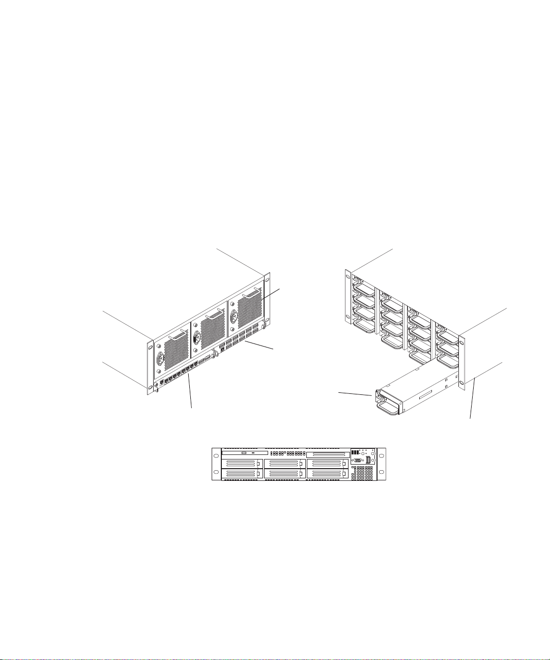
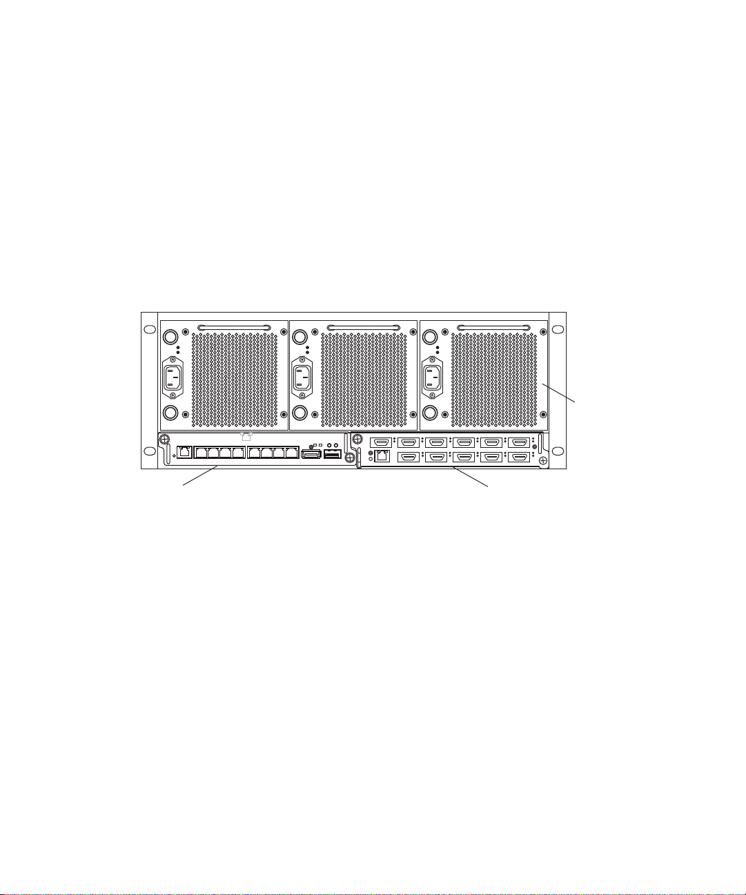
Basic Avid ISIS 7000 Shared Storage Network Hardware
Rear view
Power supply
ISIS Integrated Expansion Switch (IXS)
ISIS Storage Blade (ISB)
ISIS Integrated Switch (ISS)
System Director front view
Front view
Engine
The following sections explain these components and some basic client configurations:
• System Director
• Engine
• Client
• Storage Configurations
23
Page 24

1 Avid ISIS 7000 System Overview
• Network Zone Configurations
• Supported Cabling
System Director
The System Director is 2U in size (see “System Director Front Panel” on page 25) and
manages the metadata by storing directory information and file attributes. The System
Director does not store the data used by share clients (for example media files), these data
files are stored on the ISBs within the engine.
The System Director password is preset to is-admin. Not not to be confused with the System
n
Director Web Page Administrator user whose default password is blank.
You can have two System Directors configured in a redundant configuration, one Active the
other Standby. If the Active System Director goes down, the Standby System Director takes
over. You need at least one System Director to run the Avid ISIS system.
System Directors, workgroup servers, and clients must all be synchronized with a common
time-of-day. For information on setting the Network Time Protocol (NTP), see “Setting-Up
Network Addresses In the Stack” on page 62.
24
The System Director provides a location to coordinate file access modes (read/write), file
locking, range locking, performance data collection, logging, file lookup, and directory
change tracking for client systems. Examples of what the System Director is able to provide
to a client or storage element are:
• Identity of all storage elements connected to the system
• Information about the ISS and IXS modules in the configuration.
• List of workspaces to include name and their unique ID number
• List of users and groups within the system
• Identity of all System Directors in the system (if you have more than one System
Director)
Page 25
System Director Front Panel
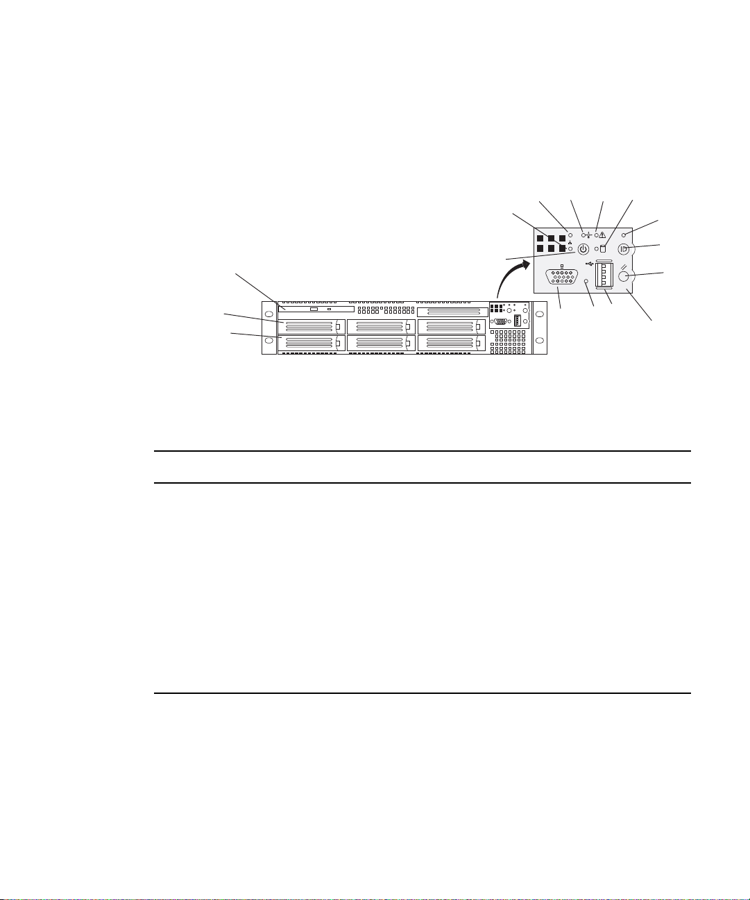
The following figure shows the front view and control panel of the System Director.
System Director Front View
System Director
DEF
C
B
G
DVD/CD-ROM
RAID disk (ID 1)
System disk (ID 0)
A
K
L
J
Control panel
The following table describes the control panel shown in the previous figure.
System Director Control Panel
Letter Description Letter Description
A Power/Sleep button G System ID LED (blue, a second system
ID LED is on the rear)
B Network port 2 activity LED H System ID button (System ID LED
blinks when pressed)
C Network port 1 activity LED I System reset button
D Power/Sleep LED J USB 2.0 connector
E System status LED K Recessed non-maskable interrupt
(NMI) button (need small tool to press)
H
I
F Internal drive activity LED L Video connector
25
Page 26
1 Avid ISIS 7000 System Overview
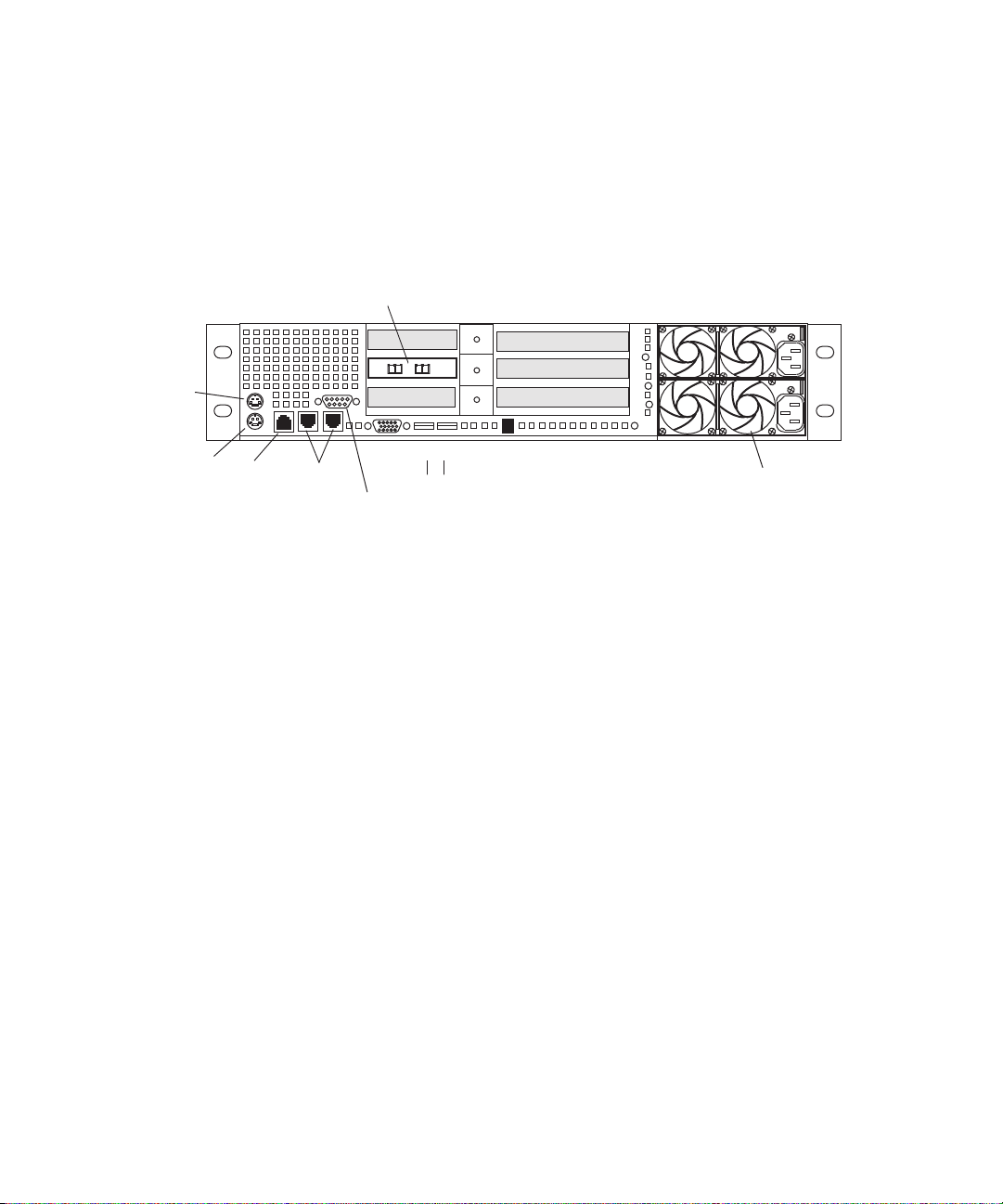
Dual NIC Ethernet
adapter board
Power supplies
Primary power
supply on bottom
Slots not used
Serial A to F/C switch if needed
Mouse
Keyboard
RJ 45 to
serial B
1 Gig
Enet
Video
USB
1
2
System Director Rear Connections
The following figure shows the rear panel of the System Director and the function of each
connection.
System Director Rear View
Second System Director
n
26
You can purchase a second System Director and configure it on the same subnets as the
original System Director. This provides a redundant System Director that is in constant
contact with the original System Director. The second System Director automatically takes
over if the original System Director fails (called failover).
For true redundancy it is recommended that you connect the second System Director to a
different engine than the first System Director.
Page 27
Engine
The engine contains the ISBs, ISSs, IXSs, power supplies, and an internal midplane. The
engine stores the data created and shared by the clients. The data is passed in and out of the
engine through the switches.
The engine contains:
• ISBs can support either 250 GB, 500 GB, or 1 terabytes (TB) drives, with two drives in
• An ISS provides connections for clients via 1000BASE-T Ethernet ports. A 10-Gb
• An IXS used when you have more than two engines (need an IXS for each subnet),
Engine
each ISB. The size of the drives are identified by the label on the front of the ISB (i500,
i1000, or i2000, respectively). As technology advances, the storage capacity of the
drives could increase, allowing the total storage per ISB/engine to increase.
Ethernet port using SFP+ transceivers connects clients or serves as an uplink port. There
is an engine interconnect port and a management port for configuration. See “Integrated
Ethernet Switches” on page 29.
allowing you to connect multiple engines providing up to 384 TB of storage, or 192 TB
of mirrored storage. See “Integrated Ethernet Switches” on page 29.
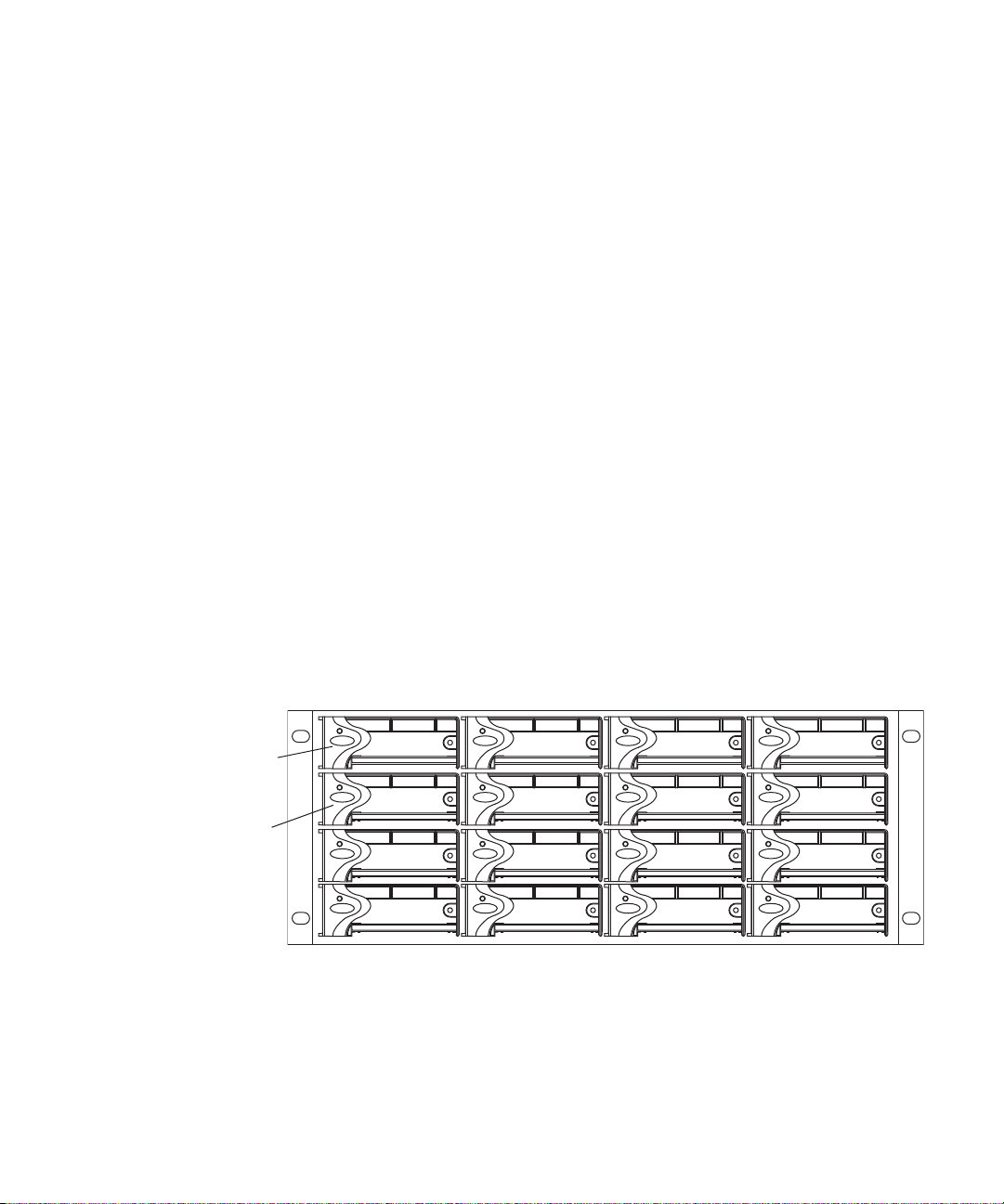
Engine Front View
The front of the engine allows access to the 16 ISBs. The first is in the upper left portion of
the front and the last ISB is in the lower right.
First ISB
Fifth ISB
Each ISB can be removed and replaced separately with the power on.
If you replace an ISB with power on, the LEDs in all of the ISBs go off momentarily. This
n
does not represent a problem. All functions are still active and working properly.
27
Page 28
1 Avid ISIS 7000 System Overview
Power supplies
IXS moduleISS module
1234 5678
12 345 6
7 8 9 10 11
Engine Rear View
The following figure shows the rear of the engine in a configuration that contains the
following:
• Three power supplies (with fans)
• Integrated Switch blade (ISS)
• Integrated Expansion Switch blade (IXS)
In a basic configuration containing two engines, each of the engines contains two ISS
n
modules. The IXS module is used with an ISS module in an engine only when the
configuration goes beyond two engines.
Power Supplies
The power supplies are powered on when the power cord is plugged in; they do not have
power switches. The power supplies not only provide power, but they also contain fans that
cool the system. The system only needs two of three power supplies to supply the needed
power to function properly. You can remove and replace a power supply temporarily while
the system is running if one fails.
c
w
28
You should leave the failing power supply in place until you replace the failing power
supply. Replace the power supply as soon as possible to maintain the proper airflow. Do
not remove the failing supply until immediately before you replace it.
Only trained Avid technicians should remove and replace the power supply while the
system is running. Since power to the system is still applied internally to the midplane
you must always keep your hands external to the engine when a power supply is
missing from the engine.
Page 29
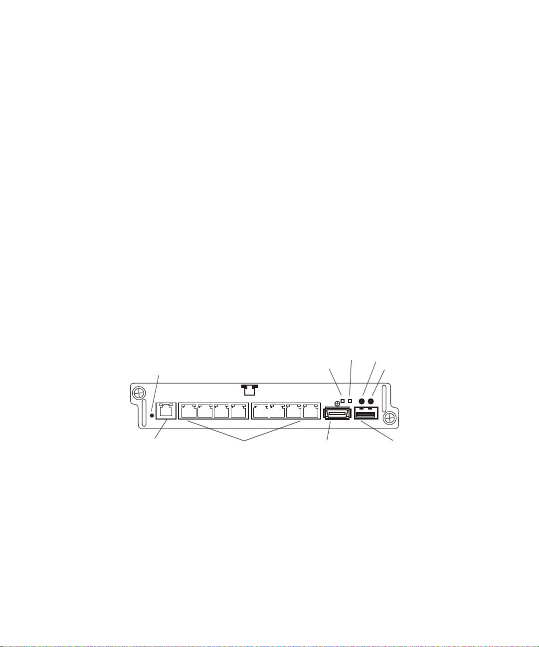
Integrated Ethernet Switches
High speed engine
interconnect (Hi-Gig)
Link
Activity
Management
connection
Link
Activity
10-Gb connection
1-Gb connections
Status
123 4 5678
ACT LINK
10 GIG
The two integrated Ethernet switches, ISS and IXS, serve different purposes and contain
different types of connections. You must have at least two switches in each engine for the
system to operate.
ISS Module
The connections on the ISS module are used for the following:
• Management connection — used to configure the Avid ISIS 7000 engine hardware
during installation. This information is used by Avid representatives to originally
configure your system before turning it over to you.
• 1-Gb (RJ-45 cable) — direct connect for clients and the System Directors.
• High speed engine interconnect (CX-4 cable) — proprietary Avid bus that connects
switch blades between engines allowing subnets to connect between the engines.
• 10-Gb XFP or SFP+ MSA form factor transceiver (for Optical cable) — used for a
10-Gb connection to a switch or 10-Gb Ethernet clients.
Engine
w
Only an Avid recommended SFP+ transceiver should be used in the 10-Gb XFP
connection, and only Avid trained representatives should remove and replace the XFP
transceiver. Currently supported XFP are the Picolight XFP and Foundry
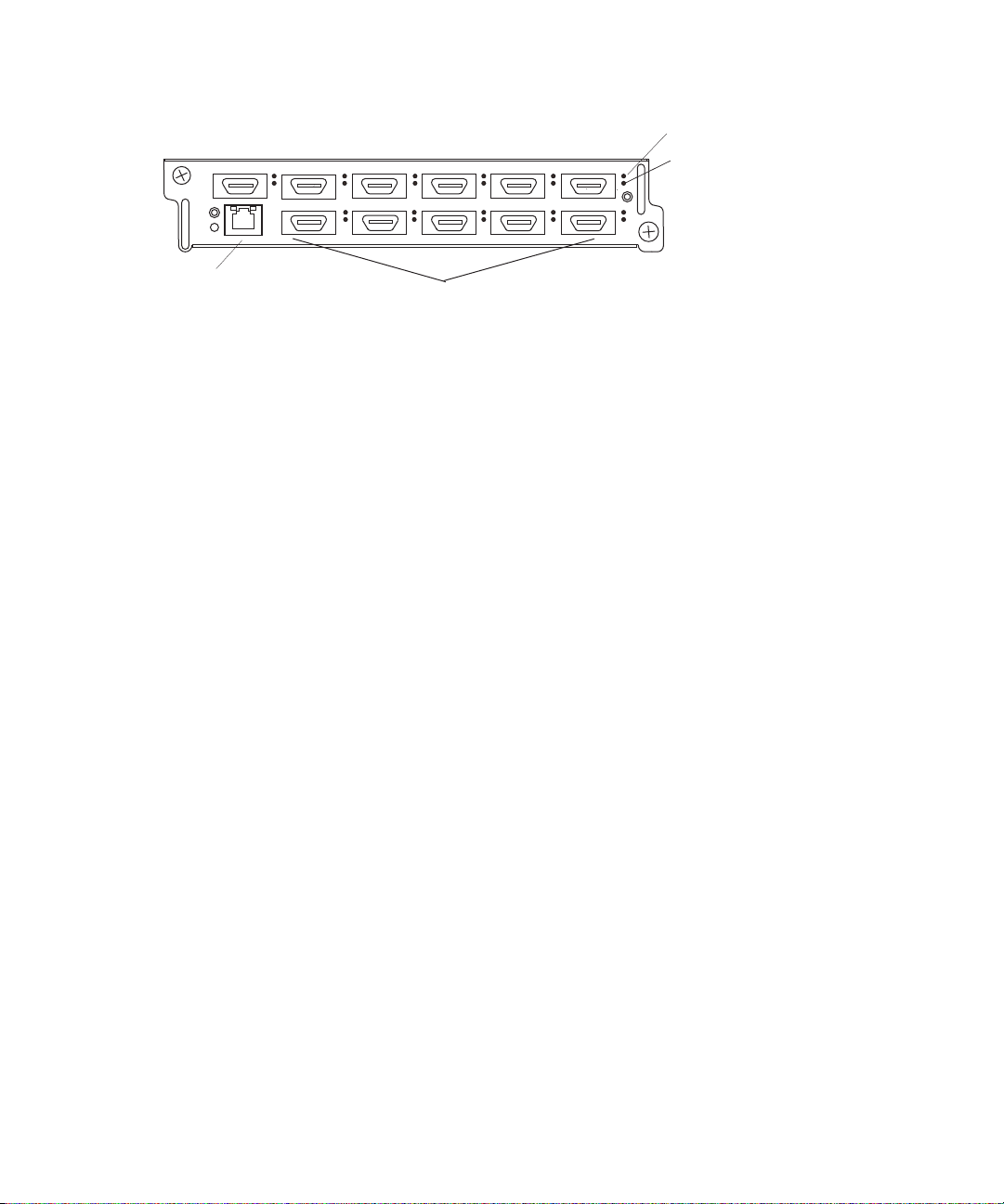
IXS Module
The IXS is needed only if you are connecting three or more engines. When connecting three
or more engines, two IXS modules are installed in one engine. The IXS offers the following
connections:
• Management connection — used to configure the switch during installation and monitor
switch functions.
• High speed engine interconnect (Hi-Gig) — proprietary Avid interconnection that
stacks the switches to create one large virtual switch.
®
XFP.
29
Page 30
1 Avid ISIS 7000 System Overview
1 2 3 4 5 6
7 8 9
10
11
Activity
Link
Management
connection
In a basic configuration containing one or two engines, each of the engines contains two ISS
n
modules. The IXS module is used with an ISS module in an engine only when the
configuration goes beyond two engines.
Storage Configurations
A maximum of twelve Avid ISIS Engines can be stacked and populated with either 250 GB,
500 GB, or 1 terabytes (TB) SATA drives. A fully populated Avid ISIS system with 1 TB
drives provides up to 384 terabytes (TB) of storage, or 192 TB of mirrored storage.
You can have mixed ISB drive sizes in an engine (250 GB, 500 GB, and 1 TB drives). You
can even mix the different size ISBs in a Storage Group. Although, the larger ISBs in the
mixed Storage Group only use the amount of storage that is available in the smaller ISBs.
Storage Group Size
Storage elements are combined to create Storage Groups in the ISIS file system. These
Storage Groups can be configured to either operate using 512 KB (default) or 256 KB chunk
sizes. Earlier Avid ISIS releases used 256 KB chunk sizes. For more information about
setting the chunk size, see the Avid ISIS 7000 Administration Guide.
Engine interconnections
10
11
Avid ISIS 7000 switch hardware shipped with v1.x (ISS1000 and IXS1000) does not support
n
512 KB chunk sizes. If you have Avid ISIS 7000 v2.x software running on v1.x switches, you
must select the 256KB chunk size when adding storage elements to the file system to create
Storage Groups.
You cannot change the chunk size of a Storage Group once the Storage Group has been
created. To change the chunk size of an existing Storage Group, you must delete the Storage
Group and create a new Storage Group with the desired chunk size. The chunk size selection
is only available when adding the storage elements.
c
30
When you delete Storage Groups all data on that Storage Group is lost.
Page 31

Moving Workspaces Between Storage Groups
You can move workspaces between Storage Groups that use the same chunk sizes.
Workspaces cannot be moved between Storage Groups of different chunk sizes (256 KB and
512 KB chunk sizes),
A Tech Alert has been written describing the process for moving data from a 256 KB chunk
size workspace to a 512 KB chunk size workspace. Search the Avid Knowledge Base at
www.avid.com/onlinesupport/ for Avid ISIS v2.x Moving Workspaces using RichCopy in the
Avid ISIS Tech Alerts.
Clients should not access workspaces that are in the process of being moved when it is a
n
256 KB chunk size workspace being moved into a Storage Group with a 512 KB chunk size.
Avid recommends that clients unmount these workspaces until the move is complete to avoid
an unintentional access. Once the move begins, it cannot be cancelled.
Adding an ISB to the File System
If you add an ISB (displays as an available storage element) to your file system, make sure
you match the chunk size of the new storage element to the chunk size of the existing storage
group. New storage elements are added with a default chunk size of 512 KB. You cannot
mix chunk sizes within a Storage Group. To change the chunk size of an ISB, you must
remove the new storage element from the file system and add the storage element again
choosing the correct chunk size.
Client
Chunk Size Support With ISB
All ISBs (i500, i1000, and i2000) support the 512 KB chunk size. Although you must have
the new v2.x switch hardware (ISS2000 and IXS2000) to use the 512 KB chunk size.
Client
A client uses services provided by the Avid ISIS architecture. The client system, using a
1 Gb or 10 Gb Ethernet connection, communicates with the ISBs through the ISS to create,
modify, and read files stored in the actual ISB. Avid ISIS 7000 supports up to 330 clients
(150 active clients), each using dual-stream video and up to 8 tracks of audio.
A client uses mechanisms specific to the operating system to display, create, and delete files
within the Avid ISIS shared storage network system. For example, when viewed from a
Windows operating system, the system sees a server containing many shares that are mapped
to drive letters.
31
Page 32

1 Avid ISIS 7000 System Overview
Network Zone Configurations
All clients in the shared storage network are classified by zones, depending on how they
connect to the network. The following list defines the clients in each network layer by their
zone classification:
A System Director must be attached to both subnets, but can only be attached once to each
n
subnet.
• Zone 1 Client — Connected to ISIS VLANs via an ISS 1 Gb or 10 GB port (direct
connect)
• Zone 2 Client — Connected to ISIS VLANs via a 1 Gb or 10 Gb port on an Avid
qualified layer-2 switch (non-routed)
• Zone 3 Client — Connected to an Avid qualified layer-3 switch (routed) with known
Quality of Service (QoS); traffic routed to ISIS (one hop) and load-balanced across ISIS
VLANs (approximately a 60/40 ratio)
• Zone 4 Client — Connected to the house network using an edge or a core switch with
unknown QoS; traffic routed to Avid ISIS (measured by the number of hops) and
load-balanced across ISIS VLANs (approximately a 60/40 ratio)
Clients which can connect to one zone can run in any lower-numbered zone — for example,
n
a Zone 3 client can also run as a Zone 2 or Zone 1 client.
Support for different client and device types vary by zone:
• Zone 1 — AirSpeed playout, Transfer Manager
• Zone 2 — AirSpeed ingest, editors, MediaManager, Interplay
• Zone 3 — MediaManager Select, Instinct, Assist, certain editors (for example,
Avid NewsCutter); typical formats include DV25, DV50/IMX-50, MPEG-2 proxy
(2 Mb/s)
• Zone 4 — MediaManager Select, Instinct, Assist; typical formats include DV25,
MPEG-2 proxy (2 Mb/s)
The following four examples show different types of Avid ISIS 7000 configurations.
Zone 1 Clients (Direct Connected)
Any client that is connected directly to an ISIS is considered a Zone 1 or direct connected
client. Each Integrated Switch Blade has a total of eight, 1 Gb Ethernet ports and one 10 Gb
Ethernet port. A single engine has the capacity to support 18 clients or servers, subtracting
any ports that are to be used by the System Director(s). The following table defines the total
32
Page 33

Network Zone Configurations
Zone 1
Chassis
interconnect
10 GB ethernet
ISS
ISS
ISSISS
Engine
Engine
Intel Pro 1000
MT/PT board
Client systems
in Zone 1
1 GB ethernet
10 GB ethernet
10 GB board
10 GB board
System Director
number of 1 Gb ports in Zone 1 based on what is available by the number of engines and
System Directors in the configuration. In addition, each ISS2000 provides a 10 Gb Ethernet
port connection for one 10 Gb client.
Connect TransferManagers and AirSpeed servers to Zone 1 or Zone 2.
n
A Zone 1 (direct connect) configuration consists of a group of clients connected directly to
the 1-Gb and 10-Gb connections of the ISS in the engine. The System Director also connects
to both subnets via both ISS modules using a 1-Gb port.
Avid ISIS 7000 Zone 1 Network Configuration
ISS1000 and IXS1000 Switches ISS2000 and IXS2000 Switches
Number
of ISIS
Engines
114121412
230283028
330
One System
Director
a
1 Gb Ports in Zone 1
Two System
Directors
(failover)
a
28
One System
Director
a
30
Two System
Directors
(failover)
a
28
33
Page 34

1 Avid ISIS 7000 System Overview
ISS1000 and IXS1000 Switches ISS2000 and IXS2000 Switches
1 Gb Ports in Zone 1
Number
of ISIS
Engines
One System
Director
Two System
Directors
(failover)
One System
Director
446444644
562606260
678767876
794929492
8 110 108 110 108
9 110
b
108
b
126 124
10 126 124 142 140
11 142 140 158 156
12 158 156 174 172
a. This is due to the use of IXS switches instead of an ISSs.
b. This is due to the use of two more IXS1000 switches instead of an ISS.
Zone 2 Clients (Indirect Connect) Configuration
There is support for external switches connected through the 10-Gb port on each ISS.
Clients that are connected to an external switch are referred to as Zone 2 clients. For a list of
supported switches, search the online Knowledge Base at www.avid.com/onlinesupport.
Two System
Directors
(failover)
34
A Zone 2 (indirect connect) configuration consists of group of clients connected to an
Ethernet switch with a 10-Gb port connected to an ISS located in the engine. The System
Director also connects to both subnets via both ISS modules using a 1-Gb port. Depending
upon the switch configuration, each client shown connected to the external switch is
connected to one of the two subnets through one of the two 10-Gb connections.
Page 35

Avid ISIS 7000 Zone 2 Network Configuration
VLAN 10 VLAN 20
10 GB ethernet
Chassis
interconnect
ISS
ISS
Engine
Engine
Zone 1
Zone 2
Intel Pro 1000
MT/PT board
Client system
in Zone 1
1 GB ethernet
External Switch with two 10-Gb Ports
System Director
Intel Pro 1000
MT/PT board
Client systems
in Zone 2
1 GB ethernet
ISSISS
Network Zone Configurations
As an example, the Foundry FES-X424 switch (see following illustration) is configured for
three VLANs with Gigabit (Gb) Ethernet ports 1 to 12 and 10-Gb Ethernet port 25 reserved
for VLAN 10 (default ISIS VLAN configuration). Gigabit Ethernet ports 13 to 23 and 10-Gb
port 26 are reserved for VLAN 20 (default ISIS VLAN configuration) and Gb port 24 is
reserved for the switch’s default VLAN. The 10-Gb ports connected to the ISIS are also
serving as uplinks to the ISIS for clients on either VLAN. Each VLAN on the Foundry
FES-X424 switch is connected to the appropriate VLAN in the shared storage network using
the 10-Gb port.
Foundry FES-X424 Switch
10-Gb ports
Por t 25 Port 2 6
1-Gb ports
Ports 1 - 12 Ports 13 - 24
Por t 24
35
Page 36

1 Avid ISIS 7000 System Overview
Each VLAN on the switch is allowed to support up to 12 connections but the size of the
Storage Groups and engine determine the overall client count. Changing the switch
configuration to increase the number of clients on a single VLAN is not supported and can
result in unpredictable system performance. Client count can be scaled according to the
number of available FES-X424 switches.
The following table provides possibilities of Zone 2 client counts based on the number of
ISIS engine and Foundry FES-X424 switches. For each engine listed in the table, there is an
associated Foundry FES-X424. The exception is with three engines, in which the IXS does
not provide additional ports.
Number of Engines FES-X424 Switch Count External Switch Ports
11 23
22 46
32 46
43 69
Available Zone 2 Ports
a
a. This is due to the use of an IXS board instead of an ISS.
The previous table does not reflect the use of Zone 1 Clients (Direct Connect), which at a
n
minimum could consist of one System Director, AirSpeed devices, and TransferManagers.
Mixing Zone 1 and Zone 2 clients in an ISIS shared storage network is discussed in the next
section.
There is no current support for an external switch to be connected with the use of a 1Gb
connection as performance for multiple clients cannot be guaranteed over a single 1Gb
connection.
Zone 1 and Zone 2 Clients Mixed Configuration
The number of ports available on the ISS (Zone 1) makes it necessary to add another layer of
clients through a qualified network switch to create a (Zone 2) in the ISIS shared storage
network.
A mixed configuration (Zone 1 and Zone 2) consists of clients connected directly and
indirectly through ports on the engine’s ISS. Also shown are two System Directors that
connect to the engine via two separate ISS 1-Gb ports for use as a redundant System
Director in case of a failure. Both System Directors also connect to each other through the
onboard Ethernet connections to monitor if one of the System Director fails.
36
Page 37

Network Zone Configurations
VLAN 10 VLAN 20
10 GB ethernet
Zone 1
Zone 2
Intel Pro 1000
MT/PT board
Client systems
in Zone 1
1 GB ethernet
External Switch with two 10-Gb Ports
Intel Pro 1000
MT/PT board
Client systems
in Zone 2
1 GB ethernet
Chassis interconnect
ISS
ISS
Engine
Engine
System Director
ISSISS
System Director
System Director
connections
1 GB ethernet
Avid ISIS 7000 Zone 1 and Zone 2 Mixed Network Configuration
n
Zone 3 and Zone 4 Client Configuration
Although it is not shown in the previous diagram, to ensure high availability, whenever
possible, the System Directors should be connected to two different subnets through two
different engines.
A Zone 3 (indirect connect) configuration consist of a group of clients connected to an Avid
qualified layer-3 switch (routed) with known Quality of Service (QoS); traffic routed to ISIS
(one hop) and load-balanced across ISIS VLANs (approximately a 60/40 ratio)
A Zone 4 (indirect connect) configuration consists of group of clients using an edge or a
house Ethernet switch with unknown QoS; traffic routed to Avid ISIS (measured by the
number of hops) and load-balanced across ISIS VLANs (approximately a 60/40 ratio)
This switch is normally connected to a house switch that has uplinks to the Avid Production
Network through an Ethernet switch that contains a 10-Gb port connected to an ISS located
in the engine. The System Director connects to the both subnets via both ISS modules using
a 1-Gb port.
37
Page 38

1 Avid ISIS 7000 System Overview
Zone 4
Zone 3
Edge switch
1 GB Ethernet
Zone 3 clients routed VLAN 40
Zone 4 clients
corporate network
VLAN 10 VLAN 20
10 GB ethernet
Zone 1
Intel Pro 1000
MT/PT board
Client systems
in Zone 1
1 GB ethernet
External Switch with two 10-Gb Ports
Chassis interconnect
ISS
ISS
Engine
Engine
System Director
ISSISS
System Director
System Director
connections
1 GB ethernet
Zone 2
House switch
Avid Production Network (Zone 1 and 2)
One to four links,
VLAN 30
Intel Pro 1000
MT/PT board
Client systems
in Zone 2
1 GB ethernet
1 GB Ethernet
Avid ISIS 7000 Zone 3 and Zone 4 Network Configuration
Link Aggregation Support
38
A link aggregation configuration supports Zone 2, Zone 3, and Zone 4 clients.
Page 39

Supported Cabling
Avid supports the following cable types for connecting a Avid ISIS system.
If you need run your cable greater distances, call Avid Customer Support for supported
n
cable and accessory information.
Supported Cables
Supported Cabling
Cable Connection
Type Function
Avid engine Interconnect
CX-4 cable. Only
available from Avid.
Ethernet network cable,
CAT5e, CAT6, or CAT6a
Connect engines. See Removing
the Avid Engine Interconnect
Cable for proper removal.
Connects:
Ethernet Avid ISIS clients
System Directors and clients to
1 Gb ports on an ISS
Avid Interplay servers to shared
storage networks
Avid AirSpeed capture and
playback servers to shared
storage networks
Avid ISIS 7000 management
port to laptop
Connector Style and Maximum Cable
Length
CX-4 connector
There are three supported lengths at this time:
1, 3, and 5 meters
RJ45 connector
100 Meters; If using CAT5e the cable must be
rated for 350 MHz for maximum length.
The minimum GigE cable length for Avid network
products is 6 feet or 2 meter.
39
Page 40

1 Avid ISIS 7000 System Overview
Supported Cables
Cable Connection
Type Function
Optical cables Connects:
10-Gb port of switch to optical
10-Gb port on the Avid ISIS
engine.
ISS 10-Gb optical port to switch
port
ISS 10-Gb optical port to 10-Gb
Ethernet Client
10-Gb Client to 10 Gb Switch
port
10-Gb Ethernet switch to 10-Gb
Ethernet Switch
Connector Style and Maximum Cable
Length
The maximum length for 10 Gb Ethernet cable is
defined by the core diameter (measured in
microns) and modal bandwidth (in units of
MHz*km).
Avid supports multi-mode fiber cable using 850
nm transceivers (short distances). Specifications
for these cables can be found in the ISO 11801
structured cabling document.
MMF 62.5 micron cable Modal Bandwidth of:
(Overfilled Launch (OFL) Bandwidth, typical of
OM1 cable)
• 160 MHz*km at 26 meters
• 200 MHz*km at 33 meters
MMF 50 micron cable Modal Bandwidth of:
• 500 MHz*km at 82 meters (Overfilled Launch
Bandwidth, typical of OM2 cable)
• 2000 MHz*km at 300 meters (Effective Modal
Bandwidth, typical of OM3 cable)
Avid supports single-mode fiber cable using
1310 nm transceivers (long distances):
• SMF ITU G.652.A/B 9 micron cable up to
10 km
When connecting to the 10 Gb port of the ISS module, it is important to follow two rules:
c
• Ensure that the cable has the required modal bandwidth for the distance of the run.
• Make sure that all multimode cables between an ISS port and the other end of the cable run are
of the same diameter (for example, 50/125 um or 62.5/125 um).
Single mode transceivers are Class 1 laser product per IEC 60825-1 Amendment 2(2001) and IEC
w
60825-2 1997. Operating this product in a manner inconsistent with intended usage and
specification may result in hazardous radiation exposure.
40
Page 41

Supported Cables
Cable disconnect
Supported Cabling
Cable Connection
Type Function
Avid ISIS
X2 optical transceivers
Avid ISIS
XFP optical transceivers
Transceiver used in:
®
Cisco
4948 and 4900M
Transceiver used in:
Foundry FESX424 and
ISIS ISS1000
Avid ISIS
SFP+ optical transceivers
Transceiver used in:
ISIS ISS2000
Connector Style and Maximum Cable
Length
SC connector
X2 = Cisco X2-10GB-SR for MMF
X2 = Cisco X2-10GB-LR for SMF
LC connector
XFP = 10G-XFP-SR for MMF
XFP = 10G-XFP-LR for SMF
XFP = Foundry 10G-XFP-SR
or Picolight XXL-SC-S45-21 for MMF
XFP = Foundry 10G-XFP-LR
or Bookham 10G-BASE-LR for SMF
LC connector
• SFP+ short range (SR)
Picolight PLRXPL-SC-S43-21-N
or Finisar FTLX8571D3BCL
or Avago AFBR-700SDZ for MMF
• SFP+ long range (LR)
Finisar FTLX1471D3BCL for SMF
Avago AFCT-701SDZL for SMF
JDSU JSH-01LWAA1 for SMF
Connecting the Engine CX-4 Cable
To connect the cable:
t Place it in the connector at the rear of the system.
You hear a snap, and the cable is connected.
41
Page 42

1 Avid ISIS 7000 System Overview
Pull back on blue
cable release
Push cable or metal
towards engine
Bottom hand
pushing cable
c
Damage can occur when disconnecting the Avid engine Interconnect cable from the
switch board if not done properly.
Care should be taken to reduce strain on the ISS switch blades by organizing and dressing
n
the ethernet cables and CX-4 cables. When dressing the cables do not block removable
switch and power components.
Removing the Avid Engine Interconnect Cable
The following explanation and illustration explain how to properly remove the engine
interconnect cable.
c
If you attempt disconnect the cable by pulling the blue cable release towards you and
pulling the cable out from the connector at the same time you can cause the cable and
or connector to be damaged.
To remove the Avid Engine Interconnect Cable from the Rear Connector:
1. While the cable is in the connector, use your bottom hand to grab the cable (or the metal
portion of the connector) and push the cable (or metal portion of the cable) towards the
connector at the rear of the engine.
2. While keeping the pressure towards the engine connector using the cable (or the metal
portion of the connector), use the top hand to pull the blue portion of the cable directly
back. This dislodges the connection of the cable from the connector.
42
3. Pull back with both hands to remove the cable.
Page 43

10-Gb Link Aggregation Overview
The 10-Gb Link Aggregation functionality supported by the Avid ISIS 7000 software is
described in the following sections. For a procedure on creating a Link Aggregation Group,
see “Configuring a 10-Gb Link Aggregation Group” on page 105. When configuring a
Hi-Gb link aggregation for ten- and twelve-engines, see “Hi-Gig Link Aggregation Group”
on page 84.
Link aggregation is a method of combining physical network links into a single logical link
for increased bandwidth. With Link aggregation, your are able to increase the capacity and
availability of the communication channel between devices (both switches and clients) using
existing Ethernet technologies. Two or more 10-Gb Ethernet connections can be combined
to increase the bandwidth capability and to create resilient and redundant links. Link
aggregation is sometimes known as “Trunking.”
Link aggregation also provides load balancing across several links in a link aggregation so
that no single link is overwhelmed.
You must disable link aggregation before creating or modifying your Avid ISIS stack. After
n
your stack has been created, reconfigure your Link Aggregation Groups.
Supported Cabling
Supported in Link Aggregation
Avid ISIS 7000 supports 10-Gb link aggregation (between the ISS and the Avid Production
Network switch) and Hi-Gig link aggregation (between two IXS). Avid ISIS software
supports the link aggregation standard clause 43 of 802.3-2005 (also known as 802.3ad).
Number of Groups Supported
A link aggregation group refers to a number of links that combine together to form a single
link aggregation. The number of link aggregation groups supported in Avid ISIS 7000 is
five.
Number of Members Supported
A link aggregation group can have a maximum of eight members. This means no more than
eight 10-Gb links can be combined into one link aggregation group per VLAN. The
minimum number of link aggregation members in a group is 2.
For performance reasons, Avid recommends that you maintain an even number of link
aggregation members. So for an eight engine stack, you can have a link aggregation group
with two, four, and six members. For a ten or twelve engine stack, there can be two, four, six,
and eight members in a link aggregation group.
If a member is already part of a link aggregation group, it cannot be part of another link
n
aggregation group. You also cannot create a link aggregation group with a single member.
43
Page 44

1 Avid ISIS 7000 System Overview
Load Balancing
The software balances the load across multiple 10-Gb aggregated links based on source and
destination IP addresses.
Failover
If a 10-Gb trunk link fails, the software load balances the traffic among the remaining trunk
links. For example in a four-way 10-Gb trunk if a single 10-Gb link fails, the traffic is load
balanced among the remaining three links. This also means that the average traffic
distribution increases from 25% with the four links, to 33% in the three links. Therefore, it is
strongly advised that network planners setup the trunks to handle the additional load if a link
or a set of links should fail in a trunk configuration. The traffic automatically re-balances the
load when a trunk link returns.
Warning messages are sent to ISIS Management Console notifying you that a 10-Gb
aggregation link status has changed. Switch diagnostics also provides errors when you have
a failed link in a trunk.
The engine menu within the ISIS Management Console flashes a yellow warning triangle
notifying you that a 10-Gb Link Aggregation link has changed. The specific engine displays
a yellow warning circle, and the Switch Blade Status displays “1 Error(s).” Details on the
engine switch displays a status of “Link Warning.” You can then open the Switch Agent page
via the “info” button on the engines details page, and look at the Port Status page to verify
the 10-Gb Link Status.
This failover feature functionality can be disable in switch agent page.
n
Recommended Topologies
For the best performance in stacks with two IXSs, the link aggregation members need to be
evenly distributed between the ISSs that are connected to each IXS. For example, with a four
link group; two are connected to ISSs that are connected to IXS A, and the other two links
are connected to ISSs that are connected to IXS B.
44
Page 45

Supported Functionality
From the Link Aggregation menu in the switch agent, you can:
• View current settings — This displays the current link aggregation configurations,
showing all currently configured groups. The user may also modify a group or delete a
group from this page.
• Create a new link aggregation group — This allows you to define a new link aggregation
group.
• Enable or disable link aggregation configuration — This allows you to disable or enable
the current link aggregation configuration. The configuration is preserved.
• Restart the link aggregation configuration — This allows you to request that the stack
restart its link aggregation configuration. This removes and rebuilds the link aggregation
groups as defined in the current configuration.
• Delete the link aggregation configuration — This disables link aggregation and removes
any existing link aggregation configuration. The configuration is not recoverable. This
can be used to set link aggregation settings back to factory defaults.
Other Functionality
Supported Cabling
• Every time a switch is introduced to the stack (by connecting the stacking cable) or
removed from the stack (by disconnecting the stacking cable), the link aggregation
software clears the link aggregation information from the switches and re-programs
them again.
• If the switches are being programmed with link aggregation information for the first
time, link aggregation needs to be enabled. This is done by clicking on “Enable or
Disable link aggregation configuration.”
45
Page 46

1 Avid ISIS 7000 System Overview
46
Page 47

2 Connecting the ISIS Equipment
This chapter explains how to rackmount and connect the system hardware. To do this, a
system installation check list is provided to help you perform the installation in the correct
order. The installation check list continues past the information in this chapter and points
you to the correct area in this document or the ReadMe file to continue the installation.
This chapter contains the following information:
• Rack-Mounting the Equipment
• Installing Blades and Power Supplies
• Connecting Power to Equipment
• Connecting the Application Key
• Connecting an Engine with v2.x Hardware
• Connecting an Engine with v1.x Hardware
For information on connecting and configuring two System Directors for failover, see
n
“Configuring the System for Failover” on page 109.
Rack-Mounting the Equipment
c
c
This chapter describes how to install and connect the System Director and other workgroup
hardware.
Information concerning power, airflow, and dimensions are explained completely in the
Avid Products and Network Site Preparation Guide located on the documentation DVD.
You should understand the basic power configurations explained in “Connecting
Power to Equipment” on page 56.
Before you start the procedures in this chapter, you should be familiar the previous
chapters in this document.
Page 48

2 Connecting the ISIS Equipment
Rack-Mounting Examples
Avid supports more than one Avid ISIS rack configuration. You should have discussed the
layout for your system with an Avid representative prior to purchase.
The following examples show a few of the supported rack configurations.
Single Rack - Two Engines - One System Director
System
Director
Engines
48
Page 49

Single Rack - Four Engines - One System Director
21345678
MGMT
A
T
S
S
UT
21345678
MGMT
SU
T
A
T
S
21345678
MGMT
A
TS
S
U
T
21 345678
MGMT
A
TSSU
T
21345678
MGMT
ATSSU
T
21 345678
MGMT
S
U
T
A
T
S
Engines
System
Director
Switch
IXS
12 34 5 6
7 8 9 10 11
12 34 5 6
7 8 9 10 11
Rack-Mounting the Equipment
49
Page 50

2 Connecting the ISIS Equipment
Dual Rack - Four Engines - Failover System
12 345 6
7 891011
U
T
A
T
21 345678
MGMT
SS
Rack 1
12 345 6
7 8 9 10 11
S
UT
A
TS
21345678
MGMT
Switch
T
A
TSSU
21345678
MGMT
T
A
TSSU
21345678
MGMT
Installing Rack-Mount Rails and Brackets
Rack 2
SU
T
A
T
21345678
MGMT
S
SU
T
A
T
21345678
MGMT
S
System
Directors
Engines
50
All Avid ISIS rack-mount components are supplied with either mounting rails or brackets.
You should follow the manufacturer’s installation instructions supplied with each
component to correctly attach the rails or brackets to the rack rails.
Where necessary, this guide supplies specific rack-mount rail or bracket installation
n
instructions. These instructions supersede the manufacturer’s instructions.
Page 51

Installing System Director and an Avid ISIS Engine
The System Director and storage elements are placed into a rack for easy access to the
cables, connectors, and drives. The following list provides recommendations you should
take into account prior to rack-mounting Avid ISIS equipment:
• The heaviest equipment should go at the bottom of the rack, for example, the Avid ISIS
engine.
• Lighter equipment goes towards the middle and top of the rack, for example, System
Directors, a Keyboard, monitor, and mouse assembly (KMM), with Ethernet switches at
the top of the rack.
• If the rack is provided with stabilizing devices, install the stabilizers before mounting
the equipment in the rack.
• Avid recommends that you leave a 1U or .5U space between each piece of equipment
mounted in the racks. This allows for better airflow and cable access, and helps stop
vibration in any equipment being transferred to spaces above and below.
• Avid recommends that you leave an 8 to 12 inch space at the bottom of the rack. This
allows for better airflow and lowers the possibility of dust or dirt being picked up by the
devices.
• If you have a redundant configuration, you might place equipment in different racks.
Place the System Director and Failover System Director in different racks, separate the
storage elements between racks, place redundant Ethernet switches in different racks,
and have the power from each rack connected to different circuits.
Rack-Mounting the Equipment
• For normal operation, you’ll need to maintain approximately 2 feet (0.6 meters) of open
space in front of and behind the rack. This allows free access to the components in the
rack for operating changes or adjustments. For service, you need approximately 3 feet
(1 meter) of open space in front of the rack and 2 feet (0.6 meters) of open space behind
the rack. This allows for the removal of any component that needs to be replaced.
For more information related to rack mounting a Avid ISIS system, see the Avid Products and
n
Network Site Preparation Guide online on the Avid Knowledge Base or the online file on
your Avid ISIS software DVD.
Mounting the Engine
w
Lifting the engine with the blades and power supplies installed can cause an injury.
The engine must have the blades and power supplies removed prior to lifting. Avid
recommends that two people be used whenever lifting the empty engine.
51
Page 52

2 Connecting the ISIS Equipment
To mount the engine into the rack:
1. Screw the brackets to the rear of the rack as shown in the following figure.
Rear
2. Make sure that the blades and power supplies are not in the engine.
3. Using two people, lift the engine and place the rear of the engine onto the brackets as
shown in the following figure.
52
4. Screw the engine to the front of the rack through the ears of the engine as shown in the
preceding figure.
Page 53

Installing Blades and Power Supplies
Installing Blades and Power Supplies
Once the engine has been mounted you can install the power supplies and blades.
w
Only trained Avid technicians should remove and replace the power supply when
power is applied to the system. Since power to the system is still on, you must always
keep your hands external to the engine when a power supply is missing from the
engine.
To place the power supplies and blades into the engine:
1. Unpack each ISB and turn it so you can properly read the Avid name.
2. Pull open the plastic handle (with drive size label) on the front of the ISB.
3. Place the ISB into the slot and slowly push the ISB completely into the slot.
4. Push the plastic handle (with drive size label) closed, to lock the ISB into the slot.
5. Repeat step 1 through step 4 until all blades are installed.
w
6. Carefully unpack each power supply.
Avid recommends that two persons be used to install the power supplies. You could be
injured if you dropped a power supply on any part of your body.
53
Page 54

2 Connecting the ISIS Equipment
Screws
7. Place the power supply into the engine as shown in the following figure and slowly push
the power supply into the slot.
8. Turn the screws until tight.
9. Repeat step 6 through step 8 until all power supplies are installed.
Installing IXS and ISS Switches
The location of the ISS and IXS switches in the stack are very important. If you have only
one or two engines you should only be installing ISS switches into the engines, see
“Two-Engine Stacking Using ISS1000s or ISS2000s” on page 64.
If you have more than two engines, you need to install two IXSs in the first engine at the top
of the stack, depending on your the version of the hardware, the following is needed:
• You need two IXS2000s in three- to twelve-engine configurations with v2.x hardware,
see “Three- to Twelve-Engine Stacking Summary With v2.x Switches” on page 66.
• You need two IXSs in three- to eight-engine configurations with v1.x hardware “Three-
to Eight-Engine v1.x Switch Connections” on page 73
• You need four IXSs in ten- to twelve-engine configurations with v1.x hardware, see
“Ten- and Twelve-Engine Stacking Summary With v1.x Switches” on page 75.
To install your IXS or ISS:
1. Unpack the switch and insert the switch edges into the internal engine slides.
2. Carefully push the switch into the midplane of the engine until the connection is made.
54
Page 55

3. Tighten the thumbscrew on each side of the switch.
IXS
Thumbscrews
Connecting the Application Key
Before you start the System Director, you need to connect the Avid ISIS system USB
application key (also called a dongle). The USB application key determines how many Avid
ISIS 7000 clients can simultaneously use your system.
Connecting the Application Key
c
c
Do not lose the USB application key. Your Avid ISIS system does not function without
it. If you lose the USB application key, you must purchase another one from Avid to use
your Avid ISIS system software.
To connect the application key to your Avid ISIS system:
1. Locate the USB application key in your Avid ISIS system kit.
2. Attach the USB application key to one of the rear USB ports of the System Director; see
“System Director Rear Connections” on page 26.
Do not use the built-in USB connector on the front of the System Director.
55
Page 56

2 Connecting the ISIS Equipment
Connecting Power to Equipment
The Avid ISIS 7000 hardware includes three power supplies using an N+1 configuration for
redundancy. The three power supplies “load share” to allow the balanced distribution of V ac
power into each Avid ISIS 7000 engine. Usually, a minimum of two of the three power
supplies must be operational at one time for the engine to function properly. The fans in each
power supply cool the supply and provides airflow for the engine. If a power supply fails,
leave it in place until you have a replacement.
Each power supply is rated at 5 amps of current capacity at 120 Vac. You can have up to one
power supply from each of the three engines on one 20-amp circuit. This allows the system
to continue running if one of the three power supplies fails, with the two remaining
load-sharing power supplies drawing slightly less than 10 amps.
Each System Director has up to two power supplies rated at 5.8 amps each. Each System
n
Director includes two power supplies. Use one 20-amp circuit for each System Director.
An engine can operate on two power supplies for a period of time to allow you to protect
data. The following illustration shows an example of how the power should be connected to
protect data.
n
c
Do not connect the power cords to the engines until instructed to do so in “Setting-Up
Network Addresses In the Stack” on page 62.
Use this section to determine how you should connect power to the engines. Place the
power cords into the engines when you place them into the rack as explained in
“Rack-Mounting the Equipment” on page 47, but do not plug them into the outlets
until told to do so later in the document.
See the following sections:
• Three 20-Amp V AC Circuits for Three Engines
• Three 20-Amp V AC Circuits for Two Engines
• Two 20-Amp V AC Circuits for Two Engines
56
Page 57

Three 20-Amp V AC Circuits for Three Engines
When you are using three 20-amp circuits for three engines, they are configured as follows:
Basic Power Connection for Three ISIS Engines
Connecting Power to Equipment
System Director
System Director
20 Amp
20 Amp
BCA
Engine
BCA
Engine
BCA
Engine
20 Amp20 Amp
20 Amp
57
Page 58

2 Connecting the ISIS Equipment
Three 20-Amp V AC Circuits for Two Engines
When using three 20-amp circuits for the engine, they are configured as follows:
First Example of Power Connection for Two ISIS Engines
System Director
System Director
BCA
Engine
BCA
Engine
20 Amp 20 Amp 20 Amp
The 20-amp circuits shown for the System Directors should remain the same for both the
n
three and two 20-amp circuit examples.
20 Amp
20 Amp
58
Page 59

Two 20-Amp V AC Circuits for Two Engines
Connecting Power to Equipment
c
The following configuration is not recommended by Avid, but some locations might
need to connect in this manner.
When using two 20-amp circuits for the engine, they are configured as follows:
Second Example of Power Connection for Two ISIS Engines
System Director
System Director
BCA
Engine
BCA
Engine
20 Amp 20 Amp
20 Amp
20 Amp
The 20-amp circuits shown for the System Directors should remain the same for both the
n
three and two 20-amp circuit examples.
Turning System On and Off
To turn the system on or off, use the following procedures. Do not turn off the Avid ISIS
components until they have completely powered on.
To turn your system on:
1. Turn on your engines one at a time by plugging at least two power cords into two power
supplies at the same time. Plug the third power cord into the third power supply soon
after the first two powers supplies have been given V ac power. Allow enough time for
all lights on the front panel to turn Green.
2. Turn on the System Directors and to start the Avid ISIS system.
3. Clients should restart there systems and use the Client Manager software to log on and
mount workspaces.
59
Page 60

2 Connecting the ISIS Equipment
To turn your system off:
1. Exit the Client Manager on all clients.
2. Stop the secondary System Director using the System Director Control Panel if you are
set up for failover.
3. Stop the Active System Director using the System Director Control Panel.
4. Turn off the System Directors.
5. Turn off the engines one at a time by unplugging the three power cords for each engine.
Connecting an Engine with v2.x Hardware
The process of connecting the engines to the Avid ISIS network is a two step process. First
you logically configure the addresses for the engine, then you physically make the
connection to complete the process. If you need to install software, see “Configuring Avid
ISIS 7000 Hardware, 10-Gb Link Aggregation, and Installing Software” on page 87.
c
c
The engines are powered on when two or three power supplies are plugged into an V ac
power source. When the engines are on, and the interconnect cables are attached, the
network tries to identify the new connection before it should. Do not connect the
interconnect cables until told to do so in the procedures.
The 64-bit System Directors introduce in Avid ISIS 7000 v2.0 can be used with v2.x and
v1.x generation switches in the engines. The two v2.x switches are branded with an IXS2000
and ISS2000 silk-screen. The v2.x switches cannot be mixed in ISIS engines with earlier
versions (v1.x) of the switches (labeled IXS1000 and ISS1000). All the switches in the
engines need to be of the same generation. For instruction on connecting v1.x hardware see
“Connecting an Engine with v1.x Hardware” on page 72.
You cannot mix new switches (labeled IXS2000 and ISS2000) with original switch
hardware (labeled ISX1000 and ISS1000). All switches in the engine, and engines in the
stack must be from the same generation of hardware.
You will need the following:
• Windows computer (laptop or System Director)
• CAT5e or CAT6 Ethernet cable to run between the Windows computer and the
Management port of the ISS or IXS
• Two or more engine interconnect cables (when using more than one engine)
• System Director DVD/CD ROM
60
Page 61

Connecting an Engine with v2.x Hardware
Engine Configuration v2.x Hardware Guidelines
Although there are a few ways to physically connect and enable the engines, Avid
recommends the process described in this section for consistency and dependability. In
smaller configurations different switch blades are used:
• ISS — Only the ISS blades are used when you are connecting two engines.
• IXS — When connecting three to twelve engines, two IXS2000 blades are used in the
first engine (one for each subnet) to connect the next eleven engines.
Engine configurations are described in the following sections:
• “Two-Engine Stacking Using ISS1000s or ISS2000s” on page 64.
• “Three- to Twelve-Engine Stacking Summary With v2.x Switches” on page 66
You must disable link aggregation before creating or modifying your Avid ISIS stack. After
n
your stack has been created, reconfigure your link aggregation.
Use the following list to help you when you connect the System Director, laptop for
configuration, and clients to the Avid ISIS 7000 system.
• A laptop (or any computer running a Windows operating system) is used in the
following examples for configuring the engine at the beginning of the installation or for
maintenance by an Avid representative. You can use the 1-Gb connection on the System
Director for configuring the engine at the beginning if needed, but do not leave it
connected or use it for a maintenance connection.
• All clients connected to the switches on the left side of the engine are connected to one
subnet, while clients connected to the switches on right side of the box are connected to
the second subnet.
• When you are connecting the System Director to the ISS module using the dual port
Ethernet board, Avid recommends that you connect the left port to the left side of the
engine and the right port to the right side of the engine. Where the left side corresponds
to the VLAN 10 subnet and right side corresponds to the VLAN 20 subnet. However, it
also functions properly the other way.
You should rename the left side, to “Left Side, VLAN 10” and the right side, to “Right
Side, VLAN 20” in the Network Properties of your System Director.
61
Page 62

2 Connecting the ISIS Equipment
Setting-Up Network Addresses In the Stack
Regardless of the number of engines you are planning in your Avid ISIS stack. The
following procedure describes how to configure the first engine.
To configure the engine:
1. Connect the power cords that are connected to the System Director to the Vac circuit
and turn on the System Director.
The System Director password is preset to is-admin. Not not to be confused with the System
n
Director Web Page Administrator user whose default password is blank.
2. Connect the power cords from at least two of the engine’s power supplies to Vac circuit
at the same time. Then connect the third power supply.
It should take about 2 minutes for the engines to reach ready status. Wait for all the
LEDS on the engine to be green.
3. Power on all the engines in the stack.
Power cords are plugged into the engines early in the process to speed up the installation
n
time. Engines can take a minute or two to become ready. If the engines are ready when it is
time to add them to the stack, the installation takes less time. Do not plug the interconnect
cables into the engines until instructed to do so.
62
4. Using a laptop (or computer running a Windows operating system), assign a static IP
address of
management port of left switch.
5. Open a browser and navigate to the Switch Agent Web page via the following address:
https://192.168.0.10:5015
6. You are asked for the default password. Type
The Avid ISIS 7000 Integrated Switch Blade Window appears.
7. Type the following into the Chassis Configuration window:
- Starting IP addresses. Enter the IP addresses for both subnets, see “IP Addressing
- Subnet mask
- Ending IP address should be the last address of the engine in the system. Remember
192.168.0.100
Overview” on page 87.
that each engine has 17 IP addresses on each side, for a total of 34. Set the ending
address high enough to cover the last engine and any possible near term future
needs.
to the network adapter (NIC) and attach it to the
.
se-admin
.
Page 63

Connecting an Engine with v2.x Hardware
If you are going to be using a Zone 3 environment you must set the default gateway
addresses for both sides of the engine. These addresses must come from the site’s IS
department.
Make sure there are no DHCP servers connected to the network segments that assign
n
addresses in the Avid ISIS range.
- Date, Time, and Time Zone or Enable network time protocol
If your network has a network time protocol (NTP) server, you can enter the IP
address of that server in the Chassis Configuration window. NTP Server 1 is for the
primary NTP server and if you have a secondary NTP server, enter the secondary IP
address in NTP Server 2.
Once the NTP is configured on a switch, the information propagates to all the other switches
n
automatically. The time is also automatically synchronized onto the storage blades after the
NTP is configured on the switch.
8. Click Submit.
A Dialog box might appear with an informational warning and can be disregarded. The
first engine is now properly addressed.
63
Page 64

2 Connecting the ISIS Equipment
Two-Engine Stacking Using ISS1000s or ISS2000s
To stack two engines:
1. Complete the procedure “Setting-Up Network Addresses In the Stack” on page 62.
2. Open a left-side Switch Web page.
3. Go to System > Configuration > Add/Remove chassis.
4. Click Add and wait for the progress bar to complete.
5. Connect the interconnect cable from the left side of the stack to the new engine. The
switch then picks up the addresses and stacking information.
Wait 5 minutes and refresh the page.
6. Verify that the serial number of the second engine is now in the Add a chassis list.
64
7. Attach the right interconnect cable.
8. Assign appropriate static IP address to the left and right network ports of the System
Director.
9. Attach the System Director to the left and right switches and verify that all four switches
can be pinged on their client IP address.
Page 65

The following example shows the physical connections between two engines, a System
Director, and clients. These are direct connections to the client system and not connected
through switches. For a procedure of this connection, see “Setting-Up Network Addresses In
the Stack” on page 62.
Two-Engine Connections
To client - RJ45 connector, CAT 5e or CAT 6
Inter-engine connection
CX-4 connector
Avid interconnect cable
Connecting an Engine with v2.x Hardware
edis thgiRedis tfeL
RJ 45 connector
CAT 5e or CAT 6
System
Director or
laptop for
configuring
only
Connection 1
US
T
TA
21345678
MGMT
S
US
T
A
T
21345678
MGMT
S
US
T
TA
21345678
MGMT
S
US
T
TA
21 345678
MGMT
S
ISS
65
Page 66

2 Connecting the ISIS Equipment
IXS module
11 Engine interconnections
Management
connection
12 345 6
7 8 9 10 11
1 2 3 4 5 6
7 8 9 10
10 1111
12 345 6
7 8 9 10 11
Three- to Twelve-Engine Stacking Summary With v2.x Switches
When connecting three- to twelve-engines, connect and add the switches to the VLAN 10
subnet (left side) first and then connect the engines to the VLAN 20 (right side) subnet.
When accessing the Agent Web pages for the engines, use your laptop through the
Management port or the Switch Agent Web through the Avid ISIS 7000 software on your
System Director. Information on installing the software on the system Director is described
in “Software Installation” on page 91.
In three- to twelve-engine configurations with ISX2000 switches, two IXSs are installed in
the first engine, see “Three- to Twelve-Engine Connections With v2.x Switches” on page 66.
The IXS2000 ports 1 through 11 are referred to from left to right as shown in the following
figure.
IXS2000 Engine Port Numbering
Three- to Twelve-Engine Connections With v2.x Switches
66
Avid strongly recommends you keep your engines and IP addresses in order in conjunction
with the order of the ports used on the IXSs. When the IP address of the engines are in order
with how they are mounted in the rack, support personnel can better identify the connections
and components in the network. For an overview of the recommended IP addressing, see “IP
Addressing Overview” on page 87.
The following procedure describes cabling up to twelve engines and might not represent
your actual rack configuration. The cabling is the same when using IXSs regardless of the
number of engines in your configuration.
Page 67

Connecting an Engine with v2.x Hardware
To connect the VLAN 10 subnet (left side):
1. Loosen the thumb screws on all the right side switches (IXS and ISS) and pull the right
side switches out about an inch of all the engines (so they are not electrically connected
in the engine).
2. Connect the power cords from at least two of the engine’s power supplies to V ac circuit
at the same time. Then connect the third power supply.
It should take about 2 minutes for the engines to reach ready status. Wait for all the
LEDS on the engine to be green.
3. Power on all the engines in the stack.
Power cords are plugged into the engines early in the process to speed up the installation
n
time. Engines can take a minute or two to become ready. If the engines are ready when it is
time to add them to the stack, the installation takes less time. Do not plug the interconnect
cables into the engines until instructed to do so.
4. Using a laptop (or computer running a Windows operating system), assign a static IP
address of
management port of left IXS.
5. Open a browser and navigate to the Switch Agent Web page via the following address:
https://192.168.0.10:5015
192.168.0.100
to the network adapter (NIC) and attach it to the
.
6. You are asked for the default password. Type
The Avid ISIS 7000 Integrated Switch Blade Window appears.
7. Type the following into the Chassis Configuration window:
- Starting IP addresses. Enter the IP addresses for both subnets, see “IP Addressing
Overview” on page 87.
- Subnet mask
- Ending IP address should be the last address of the engine in the system. Remember
that each engine has 17 IP addresses on each side, for a total of 34. Set the ending
address high enough to cover the last engine and any possible near term future
needs.
If you are going to be using a Zone 3 environment you must set the default gateway
addresses for both sides of the engine. These addresses must come from the site’s IS
department.
Make sure there are no DHCP servers connected to the network segments that assign
n
addresses in the Avid ISIS range.
- Date, Time, and Time Zone or Enable network time protocol
se-admin
.
67
Page 68

2 Connecting the ISIS Equipment
If your network has a network time protocol (NTP) server, you can enter the IP
address of that server in the Chassis Configuration window. NTP Server 1 is for the
primary NTP server and if you have a secondary NTP server, enter the secondary IP
address in NTP Server 2.
Once the NTP is configured on a switch, the information propagates to all the other switches
n
automatically. The time is also automatically synchronized onto the storage blades after the
NTP is configured on the switch.
68
8. Click Submit.
A Dialog box might appear with an informational warning and can be disregarded. The
first engine is now properly addressed.
9. Click Add/Remove Chassis to go to the Add a Chassis page.
Page 69

Connecting an Engine with v2.x Hardware
Add
10. Click Add and wait for the progress bar to complete.
69
Page 70

2 Connecting the ISIS Equipment
1 2 3 4 5 6
7 8 9 10
10 1111
Third engine
Fourth engine
Fifth engine
Sixth engine
Seventh engine
Second engine
Eighth engine
Ninth engine
Tenth engine
Eleventh engine
Twelfth engine
12 345 6
7 8 9 10 11
12 345 6
7 8 9 10 11
21345678
MGMT
S
T
A
T
U
S
21345678
MGMT
S
T
AT
U
S
11. Immediately attach an interconnect cable from port 1 of the left IXS to the left ISS
interconnect port of the second engine.
Left Subnet Twelve-Engine Connections
70
It is not mandatory that you connect each engine to the exact ports shown in the illustration.
n
The order of the ports and engines shown was suggested just to keep the stack logically
organized.
12. Verify that the switch was added to the stack successfully.
The serial number of the new engine appears in the Add/Remove Chassis list after a few
moments when the switch is successfully added. If the new engine does not appear in
the list (times out), see “Engine Does Not Appear in Add Chassis List” on page 99. You
can also navigate to the Tools tab and verify that IXS can ping the added switch via the
expected client IP address.
13. Repeat steps 9 through 11 until eleven engines are connected. Connect the third engine
to port 2, fourth engine to port 3, and so on, until all engines are connected to ports 1
through 11 on left subnet (VLAN 10).
14. Attach the System Director to client port and assign an appropriate IP address for the
left subnet. Verify that you can ping all the switches in the left stack at the expected
IP addresses.
15. Continue with the following procedure to connect VLAN 20 (right side).
Page 71

Connecting an Engine with v2.x Hardware
1 2 3 4 5 6
7 8 9
10
11
To connect the VLAN 20 subnet (right side)
1. Insert right IXS (right-side switch in the top engine) and tighten the thumb screws.
The IXS switch starts when inserted, allow the switch 2 minutes to power on and enter a
ready state.
2. Insert the right side ISSs that you intend on connecting to right IXS subnet and tighten
the thumb screws.
Allow the switches 2 minutes to power on and enter a ready state.
3. Connect the second engine to port 1, third engine to port 2, and so on, until all engines
are connected to ports 1 through 11 on right subnet (VLAN 20).
Do not click “Add” from any IXS Agent Web page.
Right Subnet Twelve-Engine Connections
Third engine
Second engine
Eighth engine
4. Attach the System Director to client port and assign an appropriate IP address for the
right subnet. Verify that you can ping all the switches in the right stack at the expected
IP addresses.
Fifth engine
Fourth engine
Ninth engine
12 345 6
7 891011
S
U
AT
T
21345678
MGMT
S
Sixth engine
Tenth engine
Eleventh engine
12 345 6
S
U
T
A
T
MGMT
S
Seventh engine
10
Twelfth engine
7 8 9 10 11
21345678
11
All switches in the stack (left and right sides) should now be pingable from the System
Director.
71
Page 72

2 Connecting the ISIS Equipment
Connecting an Engine with v1.x Hardware
The Avid ISIS 7000 hardware connection described in this section does not apply to the
currently shipping hardware. Although the latest Avid ISIS 7000 software can be installed
on all Avid ISIS 7000 hardware, these more than likely apply to Avid ISIS 7000 stakes that
are already running. There procedures are provided for reference or rebuilding a stack that
uses v1.x switches. If you need to install software, see “Configuring Avid ISIS 7000
Hardware, 10-Gb Link Aggregation, and Installing Software” on page 87. For instruction on
connecting v2.x hardware see “Connecting an Engine with v2.x Hardware” on page 60.
Engine configurations are described in the following sections:
• “Two-Engine Stacking Using ISS1000s or ISS2000s” on page 64 — There is no
difference between the v1.x and v2.x hardware connection process
• Three- to Eight-Engine v1.x Switch Connections — There is no difference between the
v1.x and v2.x hardware connection with the process “Three- to Twelve-Engine
Connections With v2.x Switches” on page 66.
• Ten- and Twelve-Engine Stacking Summary With v1.x Switches
• Ten- and Twelve-Engine v1.x Switch Connections
• Expanding to a Ten or Twelve v1.x Engine Stack
• Hi-Gig Link Aggregation Group
Engine Configuration v1.x Hardware Guidelines
Although there are a few ways to physically connect and enable the engines, Avid
recommends the process described in this section for consistency and dependability. In
smaller configurations different switch blades are used:
• ISS — Only the ISS blades are used when you are connecting two engines.
• IXS — When connecting three to eight engines, you must use at least two IXS blades
(one in each subnet) to connect each engine. Ten- and Twelve engine configurations
require at least four IXS blades.
c
72
You cannot mix new switches (labeled IXS2000 and ISS2000) with original switch
hardware (labeled ISX1000 and ISS1000). All switches in the engine, and engines in the
stack must be from the same generation of hardware.
Page 73

Connecting an Engine with v1.x Hardware
Use the following list to help you when you connect the System Director, laptop for
configuration, and clients to the Avid ISIS system.
• A laptop (or any computer running a Windows operating system) is used in the
following examples for configuring the engine at the beginning of the installation or for
maintenance by an Avid representative. You can use the 1-Gb connection on the System
Director for configuring the engine at the beginning if needed, but do not leave it
connected or use it for a maintenance connection.
• If you are re-staking your ISIS system, you must disconnect the Hi Gig link aggregation
before creating or modifying your Avid ISIS stack. After your stack has been created,
reconfigure your link aggregation.
• The new 64-bit System Directors can be used with new and old generation switches in
the engines. Although, all the switches in the engines need to be of the same generation.
• All clients connected to the switches on the left side of the engine are connected to one
subnet, while clients connected to the switches on right side of the box are connected to
the second subnet.
• When you are connecting the System Director to the ISS module using the dual port
Ethernet board, Avid recommends that you connect the left port to the left side of the
engine and the right port to the right side of the engine. Where the left side corresponds
to the VLAN 10 subnet and right side corresponds to the VLAN 20 subnet. However, it
also functions properly the other way.
You should rename the left side, to “Left Side, VLAN 10” and the right side, to “Right
Side, VLAN 20” in the Network Properties of your System Director.
• When creating ten- and twelve-engine configurations, your stack must be balanced with
with the same amount of engines on each IXS in each subnet. In other words, the two
IXSs on each subnet must have the same number used.
Three- to Eight-Engine v1.x Switch Connections
The following example shows the physical connections between four engines, a System
Director, and clients. These are direct connections to the client system and not connected
through switches. Although the example shows four engines, the process is the same for
connecting up to eight engines, see “Three- to Twelve-Engine Connections With v2.x
Switches” on page 66.
The initial release of Avid ISIS 7000 illustrated one IXS in each engine. The following figure
n
shows two IXSs in the same engine. You do not need to reconfigure your engines to move the
IXSs to the same engine unless you are upgrading your Avid ISIS 7000 environment to a tenor twelve-engine configuration.
73
Page 74

2 Connecting the ISIS Equipment
Three to Eight-Engine Connections
IXS
System
Director or
laptop for
configuring
only
21345678
T
AT
21345678
MGMT
SSU
U
T
AT
SS
U
T
AT
MGMT
SS
MGMT
edis thgiRedis tfeL
Inter-engine
connection
RJ 45 connector,
CAT 5E or CAT 6
Management port
connection
21 345678
21 345678
74
SUT
ATS
21345678
MGMT
UT
AT
MGMT
SS
21 345678
ISS
Page 75

Connecting an Engine with v1.x Hardware
IXS module
Engine interconnections
Management
connection
Port 1 Port 2 Port 3 Por t 4 Port 5 Port 6 Port 7
Ten- and Twelve-Engine Stacking Summary With v1.x Switches
When connecting a ten- or twelve-engine stack with Avid ISIS 7000 v1.x hardware, you
need to connect the engines before configuring the link aggregations. If you are upgrading
from a eight or less engine configuration, see “Expanding to a Ten or Twelve v1.x Engine
Stack” on page 84.
When configuring Avid ISIS 7000 for a ten- or twelve-engine configurations, connect and
add the switches to the VLAN 10 subnet (left side) first and then connect the engines to the
VLAN 20 (right side) subnet. When accessing the Agent Web pages for the engines, use
your laptop through the Management port. Although the Switch Agent Web page can be
accessed through the Avid ISIS 7000 software on your System Director, that is not the
recommended process in this procedure. Information on installing the software on the
system Director is described in “Software Installation” on page 91.
The IXS1000 ports are referred to from left to right as 1 through 7 shown in the following
figure.
IXS Engine Port Numbering (v1.x Switch)
In ten- and twelve-engine configurations, four IXSs are installed in the first two engines
(two IXSs in each engine). In the following procedure the four IXSs are identified as
follows:
• IXS A — The first IXS on the left side; (first engine, VLAN 10)
• IXS B — The second IXS on the left side; (second engine, VLAN 10)
• IXS C — The first IXS on the right side; (first engine, VLAN 20)
• IXS D — The second IXS on the right side; (second engine, VLAN 20)
75
Page 76

2 Connecting the ISIS Equipment
Avid strongly recommends you keep your engines and IP addresses in order in conjunction
with the order of the ports used on the IXSs. When the IP address of the engines are in order
with how they are mounted in the rack, support personnel can better identify the connections
and components in the network. For an overview of the recommended IP addressing, see “IP
Addressing Overview” on page 87.
Ten- and Twelve-Engine v1.x Switch Connections
The following procedure focuses on the cabling and might not represent your actual rack
configuration.
To connect the VLAN 10 subnet (left side):
1. Loosen the thumb screws on the right side switches (ISX and ISS) and pull the right side
switches out about an inch of all the engines (so they are not electrically connected in
the engine).
2. Connect the power cords from at least two of the engine’s power supplies to Vac circuit
at the same time. Then connect the third power supply.
It should take about 2 minutes for the engines to reach ready status. Wait for all the
LEDS on the engine to be green.
3. Power on all the engines in the stack.
76
Power cords are plugged into the engines early in the process to speed up the installation
n
time. Engines can take a minute or two to become ready. If the engines are ready when it is
time to add them to the stack, the installation takes less time. Do not plug the interconnect
cables into the engines until instructed to do so.
4. Using a laptop (or computer running a Windows operating system), assign a static IP
address of 192.168.0.100 to the network adapter (NIC) and attach it to the management
port of IXS A.
5. Open a browser and navigate to the Switch Agent Web page via the following address:
https://192.168.0.10:5015
6. You are asked for the default password. Type
The Avid ISIS 7000 Integrated Switch Blade Window appears.
7. Type the following into the Chassis Configuration window:
- Starting IP addresses. Enter the IP addresses for both subnets, see “IP Addressing
Overview” on page 87.
- Subnet mask
.
se-admin
.
Page 77

Connecting an Engine with v1.x Hardware
- Ending IP address should be the last address of the engine in the system. Remember
that each engine has 17 IP addresses on each side, for a total of 34. Set the ending
address high enough to cover the last engine and any possible near term future
needs.
If you are going to be using a Zone 3 environment you must set the default gateway
addresses for both sides of the engine. These addresses must come from the site’s IS
department.
Make sure there are no DHCP servers connected to the network segments that assign
n
addresses in the Avid ISIS range.
- Date, Time, and Time Zone or Enable network time protocol
If your network has a network time protocol (NTP) server, you can enter the IP
address of that server in the Chassis Configuration window. NTP Server 1 is for the
primary NTP server and if you have a secondary NTP server, enter the secondary IP
address in NTP Server 2.
Once the NTP is configured on a switch, the information propagates to all the other switches
n
automatically. The time is also automatically synchronized onto the storage blades after the
NTP is configured on the switch.
77
Page 78

2 Connecting the ISIS Equipment
8. Click Submit.
A Dialog box might appear with an informational warning and can be disregarded. The
first engine is now properly addressed.
9. Click Add/Remove Chassis to go to the Add a Chassis page.
10. Click Add and wait for the progress bar to complete.
c
c
11. Immediately attach an interconnect cable from port 6 of IXS A to port 6 of IXS B (in the
second engine).
You must use port 6 to connect the IXS to another IXS. Ports 1 through 5 can only be
use to connect ISSs.
12. Verify that the switch was added to the stack successfully.
The serial number of the new engine appears in the Add/Remove Chassis list after a few
moments when the switch is successfully added. If the new engine does not appear in
the list (times out), see “Engine Does Not Appear in Add Chassis List” on page 99. You
can also navigate to the Tools tab and verify that IXS A can ping the added switch via
the expected IP address.
Do not connect both ports 6 and 7 before the IXS’s are configured for link aggregation.
If two stacking cables are connected between the IXS’s without link aggregation
enabled, then traffic loops occur. For information in correcting a traffic loop, see
“Recovering from Stacking Problems” on page 128.
13. Go back to the Add/Removed Chassis pane and click Add Chassis from IXS A’s Agent
Web page using the IXS management port.
14. Connect an interconnect cable from the left side of a third engine to port 1 of IXS A (not
the engine with IXS B).
15. Verify that the new switch was added to the stack successfully as previously described.
78
Page 79

Connecting an Engine with v1.x Hardware
If watching the progress in the Switch Agent Web page, only side 0 of each engine is of
n
interest. Requests to side 1 are expected to time out because the right side is not connected.
VLAN 10 Twelve-Engine Connections (IXS A)
Connection summary
Third engine
VLAN 10 Inter-engine
connections
IXS A
2 4 1 3 5 6 7
Four th engine
Fifth engine
Sixth engine
Seventh engine
Second engine
(to IXS B port 6)
VLAN 20 Inter-engine
connections (not shown)
IXS A
IXS B
VLAN 10 VLAN 20
S
U
AT
T
MGMT
S
S
ATU
MGMT
ST
S
MGMT
STATU
21345678
21345678
21345678
S
U
T
A
T
MGMT
S
S
U
T
A
T
MGMT
S
S
U
T
A
T
MGMT
S
21345678
21345678
21345678
IXS C
IXS D
VLAN 10 VLAN 20
S
U
T
A
T
21345678
MGMT
S
S
U
T
A
T
21345678
MGMT
S
21345678
21345678
S
U
T
A
T
21345678
MGMT
S
S
U
T
A
T
MGMT
S
S
U
T
A
T
MGMT
S
S
U
T
A
T
MGMT
S
S
U
T
A
T
MGMT
S
S
U
T
A
T
MGMT
S
21345678
21345678
21345678
21345678
21345678
S
U
T
A
T
MGMT
S
21345678
S
U
T
A
T
MGMT
S
21345678
S
U
T
A
T
MGMT
S
21345678
S
U
T
A
T
MGMT
S
21345678
16. Repeat steps 9 through 15 until five engines are connected. Connect the third engine to
port 2, fourth engine to port 3, and so on, until five engines are connected to ports 1
through 5 on IXS A.
79
Page 80

2 Connecting the ISIS Equipment
21345678
MGMT
STAT
U
S
21345678
MGMT
S
T
A
T
U
S
21345678
MGMT
S
T
AT
U
S
21345678
MGMT
S
T
A
T
U
S
21345678
MGMT
ST
ATUS
21345678
MGMT
S
T
A
T
U
S
21345678
MGMT
ST
AT
US
21345678
MGMT
S
T
A
T
U
S
21 345678
21 345678
21345678
MGMT
S
T
A
T
U
S
21345678
MGMT
S
T
A
T
U
S
21345678
MGMT
S
T
A
T
U
S
21345678
MGMT
S
T
A
T
U
S
21345678
MGMT
S
T
A
T
U
S
21345678
MGMT
S
T
A
T
U
S
21345678
MGMT
S
T
A
T
U
S
21345678
MGMT
S
T
A
T
U
S
21 345678
MGMT
S
T
A
T
U
S
21345678
MGMT
S
T
A
T
U
S
VLAN 10 VLAN 20
VLAN 20 Inter-engine
connections (not shown)
VLAN 10 Inter-engine
connections
IXS A
IXS B
VLAN 10 VLAN 20
IXS C
IXS D
Eighth engine
IXS B
2 4 1 3 5 6 7
Ninth engine
Tenth engine
Eleventh engine
Twelfth engine
First engine
(to IXS A port 6)
Connection summary
If you are connecting a ten-engine Avid ISIS 7000 configuration, connect engines to ports
n
1 through 4 leaving port 5 empty on IXS A, IXS B, IXS C, and IXS D.
17. Click Add Chassis from IXS A’s Agent Web page using the IXS management port.
18. Connect an interconnect cable from the left side of a sixth engine to port 1 of IXS B.
VLAN 10 Twelve-Engine Connections (IXS B)
80
Page 81

Connecting an Engine with v1.x Hardware
19. Verify the engine appears in the Switch Agent Web page.
The new engine appears in the list after a few moments. If the new engine does not
appear in the list (times out), see “Engine Does Not Appear in Add Chassis List” on
page 99.
20. Repeat step 17 through 19 until five engines are connected to IXS B. Connect the ninth
engine to port 2, tenth engine to port 3, and so on, until five engines are connected to
ports 1 through 5 on IXS B.
At this time, there should not be any stacking cables in port 7 of either IXS A or IXS B.
n
21. Attach the System Director to client port and assign an appropriate IP address for the
left subnet. Verify that you can ping all the switches in the left stack at the expected
IP addresses.
22. Continue with the following procedure to connect VLAN20 (right side).
To connect the VLAN 20 subnet (right side)
1. Insert IXS C and IXS D (first and second right side switches in the top two engines) and
tighten the thumb screws.
The IXS switches start when inserted, allow the switches 2 minutes to power on and
enter a ready state.
Make sure IXS C is installed in the same engine as IXS A and IXS D is installed in the same
n
engine as IXS B.
2. Connect port 6 of IXS C to port 6 of the remaining IXS (IXS D).
Do not click “Add” from any IXS Agent Web page.
3. Verify that the new engine appeared in the Switch Agent Web page.
The new engine appears in the list after a few moments. If the new engine does not
appear in the list (times out), see “Engine Does Not Appear in Add Chassis List” on
page 99.
4. Insert the right side ISSs that you intend on connecting to IXS C and tighten the thumb
screws.
Allow the switches 2 minutes to power on and enter a ready state.
5. Connect the third engine to port 2, fourth engine to port 3, and so on, until five engines
are connected to ports 1 through 5 on IXS C.
81
Page 82

2 Connecting the ISIS Equipment
Do not click “Add” from any IXS Agent Web page.
VLAN 20 Twelve-Engine Connections (IXS C)
Connection summary
VLAN 10 Inter-engine
connections (not shown)
IXS C
2 4 1 3 5 6 7
Fourth engine
Fifth engine
Sixth engine
Seventh engine
Second engine
Third engine
(to IXS C port 6)
VLAN 20 Inter-engine
connections
IXS A
IXS B
VLAN 10 VLAN 20
S
U
AT
T
MGMT
S
S
ATU
MGMT
ST
S
MGMT
STATU
21345678
21345678
21345678
S
U
T
A
T
21345678
MGMT
S
S
U
T
A
T
MGMT
S
S
U
T
A
T
21345678
MGMT
S
21345678
IXS C
IXS D
VLAN 10 VLAN 20
S
U
T
A
T
21345678
MGMT
S
S
U
T
A
T
21345678
MGMT
S
21345678
21345678
S
U
T
A
T
21345678
MGMT
S
S
U
T
A
T
MGMT
S
S
U
T
A
T
MGMT
S
S
U
T
A
T
MGMT
S
S
U
T
A
T
MGMT
S
S
U
T
A
T
MGMT
S
21345678
21345678
21345678
21345678
21345678
82
S
U
T
A
T
MGMT
S
21345678
S
U
T
A
T
MGMT
S
21345678
S
U
T
A
T
MGMT
S
21345678
S
U
T
A
T
MGMT
S
21345678
6. Insert the right side ISSs that you intend on connecting to IXS D (remaining ISSs) and
tighten the thumb screws.
Allow the switches 2 minutes to power on and enter a ready state.
Page 83

Connecting an Engine with v1.x Hardware
7. Connect the ninth engine to port 2, tenth engine to port 3, and so on, until five engines
are connected to ports 1 through 5 on IXS D.
Do not click “Add” from any IXS Agent Web page.
At this time, there should not be any stacking cables in port 7 of either IXS C or IXS D.
n
VLAN 20 Twelve-Engine Connections (IXS D)
Connection summary
Eighth engine
VLAN 10 Inter-engine
connections (not shown)
IXS D
2 4 1 3 5 6 7
Ninth engine
Tenth engine
Eleventh engine
Twelfth engine
First engine
(to IXS C port 6)
VLAN 20 Inter-engine
connections
IXS A
IXS B
VLAN 10 VLAN 20
S
U
T
A
T
MGMT
S
S
MGMT
STATU
TATUS
MGMT
S
21345678
21345678
21345678
S
U
T
A
T
MGMT
S
S
U
T
A
T
MGMT
S
S
U
T
A
T
MGMT
S
21345678
21345678
21345678
IXS C
IXS D
VLAN 10 VLAN 20
S
U
T
A
T
21345678
MGMT
S
S
U
T
A
T
21345678
MGMT
S
21345678
21345678
S
U
T
A
T
21345678
MGMT
S
S
U
T
A
T
MGMT
S
S
U
T
A
T
MGMT
S
S
U
T
A
T
MGMT
S
S
U
T
A
T
MGMT
S
S
U
T
A
T
MGMT
S
21345678
21345678
21345678
21345678
21345678
S
TU
A
T
21345678
MGMT
S
S
U
T
A
T
MGMT
S
21345678
S
U
T
A
T
21345678
MGMT
S
S
U
T
A
T
MGMT
S
21345678
83
Page 84

2 Connecting the ISIS Equipment
8. Attach the System Director to client port and assign an appropriate IP address for the
right subnet. Verify that you can ping all the switches in the right stack at the expected
IP addresses.
9. Continue with “Hi-Gig Link Aggregation Group” on page 84.
Expanding to a Ten or Twelve v1.x Engine Stack
If you already have a Avid ISIS 7000 media network and your are expanding the number of
engines in your Avid ISIS 7000 stack to ten or twelve engines, you need to changes the
switch (IXS) configuration in the engines.
The upgrade process is summarized as follows:
1. Upgrade your current Avid ISIS 7000 components to the latest software, see “Software
Upgrade” on page 133:
a. Upgrade the System Director software.
b. Upgrade the switch firmware.
c. Upgrade the ISB firmware.
2. Record your existing IP address for the engines in your current stack.
3. Using a laptop (or computer running a Windows operating system), assign a static IP
address of 192.168.0.100 to the network adapter (NIC) and attach it to the management
port of your left subnet IXS.
4. Navigate to the Add/Remove Chassis tab, and remove all engines from the list except
the first engine in the list.
5. Reconfigure your existing configuration to a ten- or twelve-engine confrontation as
follows:
a. Remove your cabling.
b. Replace the ISSs so that your first two engines contain the four IXSs in the first two
engines at the top of your stack.
6. Continue with the procedure for the “Ten- and Twelve-Engine Stacking Summary With
v1.x Switches” on page 75.
Hi-Gig Link Aggregation Group
Two interconnect cables and Link Aggregation are used to increase the bandwidth between
the IXS’s. However, both interconnect cables must not be connected until Hi-Gig Link
Aggregation is Enabled. Link Aggregation must be enabled for both sides of the network in
order for clients on both sides to perform I/O operations.
84
Page 85

Connecting an Engine with v1.x Hardware
c
c
If Hi-Gig Link Aggregation is not enabled, and two interconnect cables are used to
connect IXS A to IXS B, then traffic loops and stacking problems occur. If you
experience stacking problems, see “Recovering from Stacking Problems” on page 128.
To enable link aggregation:
1. Go to any left subnet Switch Agent Web page.
Notice on the left hand column of the System page there is an option Hi Gig Link
Aggregation with an Enable/Disable radio button.
2. Click Enable/Disable.
3. Click the radio button to Enable Hi Gig Link Aggregation.
4. Click submit, the IXS’s restart.
5. After the IXS has restarted, check that Hi Gig is “on” in the Hi Gig Link Aggregation
column of the System page > Switch Agent > Management Domain.
6. Connect a stacking cable from port 7 on IXS A to port 7 on IXS B.
7. Connect a stacking cable from port 7 on IXS C to port 7 on IXS D.
Currently only Port 6 and Port 7 can be used for Hi-Gig Link Aggregation. Do not use
any other stack ports to connect the IXS’s to each other.
85
Page 86

2 Connecting the ISIS Equipment
86
Page 87

3 Configuring Avid ISIS 7000 Hardware,
10-Gb Link Aggregation, and Installing
Software
This chapter describes how to connect and configure the System Director and other
Avid ISIS hardware. Since the number of different configurations are endless, it uses a
configuration with four engines and one System Director as an example.
If you have questions, please call your Avid representative or your local ACSR.
c
Before you start the procedures in this chapter, you should be familiar with the
information in previous chapters and the Avid Products and Network Site Preparation
Guide.
This chapter contains the following sections:
• IP Addressing Overview
• Configuration Overview
• Software Installation
• Configuring a 10-Gb Link Aggregation Group
IP Addressing Overview
Before you attempt to define a total IP addressing scheme for your system and configure the
static internal IP addresses of the engine, you should have a solid understanding of how the
addresses are assigned within the engine and how the IP addresses increment between
engines.
192.168.10.10 and 192.168.20.10, subnet 10 and subnet 20, are used by Avid as examples
n
throughout this document, your site might require different addresses. Consult with your
site’s networking managers for site specific requirements. Unless specified, you can change
the addresses used in the following example to suit your needs. However, whichever static IP
addresses are assigned within the engine, they must not be assigned by a DHCP server to
any other device within the Network.
Page 88

3 Configuring Avid ISIS 7000 Hardware, 10-Gb Link Aggregation, and Installing Software
raeRtnorF
Upper left
Lower right
Right side
(default subnet 20)
Left side
(default subnet 10)
Management Port
Management Port
The IXS shown is only
used when three or more
engines are connected.
1234 5678
12 345 6
7 891011
The following figure shows the front and rear view of a engine. Use the following two
figures and bulleted list to understand how static IP addresses are assigned to each engine.
Front and Rear of a Engine
The following list describes what needs to be accomplished to assign IP addresses to
engines. You should understand the assignment of IP addresses completely before you
perform the actual configuration.
88
Do not attempt to assign addresses to the engine using this list. This provides an overview,
n
not a step-by-step procedure.
• Connect Port 1 of the System Director or a port on a laptop to the Management Port of
the ISS in the bottom engine of the rack using a CAT5 E, CAT6 cable or better. See the
previous figure.
• You are now talking to the Management Port on an isolated network interface on the ISS
using the default IP address of 192.168.0.10. This IP address is used on every the
Management Port on the ISS and expansion switch blade. The address is not on the local
10 or 20 subnets Ethernet bus and is never used to transfer actual data.
Page 89

IP Addressing Overview
When you assign subnet addresses internally and have more than one engine, all ISSs and
n
IXSs on the left side of the rear of the engine are on one subnet, while all ISSs and IXSs on
the right side of the rear of the engine are on the other subnet.
See the following illustration for a pictorial view of address assignments described in the
following bullet.
• Then two static IP addresses are assigned to the upper left-most ISB slot in the engine
when looking at the engine from the front. The addresses are 192.168.10.10 on
subnet 10 and 192.168.20.10 on subnet 20. You are assigning the address to the slot, not
the blade. The ISB can be physically moved, but the IP address remains with the slot.
• As the slots go sequentially from top left to right, over a row and starting at the left
again, each slot is assigned a static IP address that is incremented by one until you reach
the right-most bottom slot that contains addresses of 192.168.10.25 and 192.168.20.25.
• At this point, each ISS or IXS is assigned a base address. One ISS is assigned a
subnet 10 address of 192.168.10.26 and the other a subnet 20 address of 192.168.20.26
(unless the you want to change the IP scheme or subnet mask). Now each side of the
engine is assigned 17 addresses on each network for a total of 34 addresses per engine.
• You then increment the subnet 10 and subnet 20 addresses by one and assign them to the
switch blades in the next engine.
• The ISB slots and switches are again incremented.
89
Page 90

3 Configuring Avid ISIS 7000 Hardware, 10-Gb Link Aggregation, and Installing Software
Static Engine Internal IP Address Assignments
First engine
Subnet 20Subnet 10
edalb hctiws/noisnapxEedalb hctiws/noisnapxE
90
Second engine
Expansion/switch blade
Expansion/switch blade
Page 91

Configuration Overview
Your System Director and engines should be rack mounted with the interconnect cables
connected to the left side of your stack as previously described before continuing.
You now need to do the following:
1. Configure the engine by assigning IP addresses to the engine. This provides each ISS,
IXS, and ISB with the needed IP addresses to connect to the clients and System
Director, see “Setting-Up Network Addresses In the Stack” on page 62.
The ghost image on the System Directors does not set the IP addresses of the two onboard
n
NICs or the dual NICs card on the PCI bus; the system is set for DHCP.
2. Load the System Director software. This software is used to create a file system on the
System Director, bind the ISBs to the software on the System Director, create Storage
groups, and administer the Avid ISIS system. See “Loading the System Director
Software” on page 91.
3. Perform administrative functions: bind ISBs (storage elements), create storage groups,
and do other administrative functions. See “Performing Basic Administrative
Functions” on page 94.
Configuration Overview
4. Load the client software; see “Loading Client Software for Zone 1 and Zone 2 Clients”
on page 100.
Software Installation
Make sure you have the application key installed, see “Connecting the Application Key” on
page 55. Your System Director and engines should be cabled and attached to both internal
subnets similar to the “Setting-Up Network Addresses In the Stack” on page 62.
Loading the System Director Software
To load the Avid ISIS software:
1. Insert the Avid ISIS software DVD into the System Director DVD drive.
The DVD automatically starts and opens a dialog box opens.
91
Page 92

3 Configuring Avid ISIS 7000 Hardware, 10-Gb Link Aggregation, and Installing Software
Avid highly recommends that you click the ReadMe button. This displays the ReadMe file
n
that provides the latest information regarding the Avid ISIS system.
2. Click the Install Product button.
The Install Products dialog box opens.
92
Page 93

Software Installation
The following table describes the Install Products dialog box buttons and their
functions.
Install Products Dialog Box Buttons
Button Function
Windows Client Click this button to load the software from the DVD on an Avid Windows client while
on the client system. This button is used for clients using Windows 32-bit and 64-bit
operating systems. The installer detects the operating system and installs the
appropriate client installer. You can also load the client remotely.
System Director Click this button to install the System Director software on the System Director. The
installer detects the operating system (Windows 32-bit and 64-bit) and installs the
appropriate software and creates the file system used by the engines; it also provides
the ISIS Management Console and error logging. See “Loading the System Director
Software” on page 91.
Also installed on the System Director are the client installers and the Storage Blade
(ISB) and switch (ISS and ISX) firmware. The installer displays messages as it
completes each installation. You need to load the switch and ISB firmware on the
engines before clients can use the Avid ISIS System. See “Loading Avid ISIS 7000
Firmware and Various Applications” on page 94.
Custom Click this button to individually select the three System Director installers. These three
installers are automatically installed when you click the System Director button on the
Install Products Dialog Box.
• ISIS Client Installers — Click this button to “install the installers” on the System
Director. Clients can then install the latest software on the clients from the System
Director Management Console Window.
• ISIS Blade Installers — Click this button to load the Storage Blade (ISB) and
switch (ISS and ISX) firmware on the System Director. You then need to load the
firmware on the switches and ISBs of the engines. See “Loading Avid ISIS 7000
Firmware and Various Applications” on page 94.
• System Director — Click this button to install the System Director software on the
System Director. The installer detects the operating system (Windows 32-bit and
64-bit) and installs the appropriate software and creates the file system used by the
engines; it also provides the ISIS Management Console and error logging. See
“Loading the System Director Software” on page 91.
File Gateway Click this button to install the Avid ISIS File Gateway software. This software cannot
be installed on the same server as the System Director software.
3. Depending if your System Director has a 32-bit or 64-bit Windows operating system,
click the appropriate System Director button in the Install Products dialog box.
A Setup Wizard opens.
93
Page 94

3 Configuring Avid ISIS 7000 Hardware, 10-Gb Link Aggregation, and Installing Software
4. Follow the instructions in the Setup Wizard when the File Location window opens with
the following exception:
5. Once the installation is complete, click close.
Loading Avid ISIS 7000 Firmware and Various Applications
This installs the ISS and ISB firmware, various client installers, and some third party
applications.
To load the Avid ISIS drivers:
1. Insert the DVD into the System Director.
The DVD automatically starts and opens a dialog box opens.
2. Click Install Products.
The Install Products dialog box opens.
3. Click ISIS Blade Installers in the Install Products dialog box and follow the Setup
Wizard instructions.
4. Click ISIS Client Installers in the Install Products dialog box.
A Setup Wizard opens.
5. Follow the instructions in the Setup Wizard with the following exception when the File
Location window opens:
Select the box that specifies Everyone in the window asking about file location.
6. Once the installation is complete, click Close.
At this time the System Director software services are operational, but the ISIS file
system is not yet operational.
Performing Basic Administrative Functions
Before you log on and use the Avid ISIS Administrator and load the remaining software on
the engines, you must initialize your system by creating a Active partition on the System
Director main drive.
94
Page 95

Software Installation
Blue Active
Mode
To create a Active partition:
1. Click Start > Programs > Avid Unity System Director and select System Director
Control Panel. The Active Mode displays as blue in the Avid ISIS System Director
Control Panel window.
2. Click the Configuration tab.
c
3. Click Stop Server
When you click Create New Active, this action results in the loss of all media assets on
the system. This is a non recoverable action and extreme caution should be exercised
when this command is invoked.
4. Click Create New Active. The server automatically restarts when complete.
5. If you are not placed in the Status Tab, click System Director Status.
95
Page 96

3 Configuring Avid ISIS 7000 Hardware, 10-Gb Link Aggregation, and Installing Software
The Standby Mode has changed to Active Mode and the light is Green.
Installing Software on the Engines
Upgrading the software on the engines should be done to make sure you have the latest
software on the engines. You can use Web Administrator from anywhere to perform the
following functions, but you usually do it from the System Director:
• Upgrade the ISS and IXS with the proper/latest software
• Upgrade the ISBs with the proper/latest software
• Create Workspaces
To upgrade the software:
1. Go to https://IP address of System Director (or virtual name):5015.
2. Log into the System Director.
The default Administrator password is blank.
n
The ISIS Management Console opens.
96
3. Click Chassis.
Page 97

4. Select the chassis you want to upgrade in the Chassis list.
Upgrade
Switch Blades
Upgrade
Storage Blades
Upgrade .tgz file
Upgrade
5. Click Upgrade Switches.
Upgrading switches takes approximately 25 minutes for the original ISIS switches and
n
10 minutes for the v2.x switch hardware (ISS2000 and IXS2000). You should upgrade
switches on all your engines at the same time.
Software Installation
After all the Switch Blades are updated, upgrade the Storage Blades.
6. Click Upgrade Blades.
The Upgrade Storage Blades window opens.
97
Page 98

3 Configuring Avid ISIS 7000 Hardware, 10-Gb Link Aggregation, and Installing Software
7. Select the upgrade file, and click Upgrade.
Each Storage Blade takes approximately 10 minutes.
8. Select the engine and click Details.
Select an engineRefresh DetailsSystem Overview Toolbar
98
The Status for the upgrade is shown in the Details pain at the right of the window. Click
the Refresh button whenever you want the updated upgrade Status. When the Status is
empty, the upgrade is complete.
Other ways to view the installation status is to use the Monitor Tool, the color indicator in
n
the System Overview Toolbar, and the Storage Blade Status column. Select the Engine
Summary in the left pane for each engine and click the Upgrade button to see the install
status graphically displayed.
9. Repeat the Software upgrade process for each Storage Blade.
Page 99

Engine Does Not Appear in Add Chassis List
If the engine did not appear in the Add/Remove page, you must stop and troubleshoot the
problem. Once the engine appears in the list, continue adding any additional engines.
Perform the following steps one at a time and wait for the Add Chassis process to time-out
before trying the next step.
To troubleshoot why an engine did not appear in Add/Remove page:
1. Reseat the interconnect cables; both sides of the interconnect should have a green solid
link light when powered on. If not:
a. Remove the cable.
b. Click Add chassis.
c. Replace cable.
2. Reseat the ISS that is being added:
a. Remove the ISS.
b. Click Add chassis.
c. Reseat ISS.
3. Try a different IXS port:
Software Installation
a. Disconnect interconnect cable from IXS port.
b. Click Add chassis.
c. Attach interconnect to a new port on the IXS.
4. Try a different a new interconnect cable:
a. Disconnect interconnect cable.
b. Click Add chassis.
c. Replace interconnect cable.
Check Switch IP Address
Telnet to the newly added switch at the expected IP address.
If the switch cannot be reached, try the following:
1. On the IXS Switch Agent, view “System Overview.”
2. Click on the link for the newly added chassis. If Peth0-IP is not correct, Set switch back
to the default.
If the IP address is correct, proceed to the next step.
99
Page 100

3 Configuring Avid ISIS 7000 Hardware, 10-Gb Link Aggregation, and Installing Software
3. Check the State Machines in “System Overview” under “Stack Port Status.” The state
for the newly connect port should eventually become “SW_PORT_STACKED.” If it
does not, try the following:
a. Reseat the interconnect cable.
b. Restart the newly connected switch.
c. Restart the IXS.
Java Runtime Environment
The Avid ISIS Management Console and Avid ISIS Client Manager requires version 6 (build
1.6) or higher of the Java Runtime Environment (JRE). Avid provides a qualified version of
JRE for Windows systems on the Avid ISIS software DVD in the [DVD
drive]:\Tools_3rdParty\Java folder.
For clients using a Macintosh system, download the Java software from the Apple
(www.apple.com) or use the Apple Software Update.
Loading Client Software for Zone 1 and Zone 2 Clients
You can load the Client software in several ways:
®
Web site
100
• You can take the DVD to each client separately and load it from the DVD.
• You can store the client software somewhere on the corporate network and allow
everyone who needs the software to gain access to it and load it.
• You can use the a Browser to reach the ISIS Management Console and load it from the
System Director because it was loaded during the previous installation of the Client
Installers.
Keep in mind the following when connecting Avid ISIS clients.
• When installing Avid ISIS client software on Windows systems, make sure you are
up-to-date with your Windows critical updates.
• Zone 1 clients must use 1 Gb connections to the ISS. The ISS does not negotiate at any
rate below 1 Gb. If 100 BASE-T connections are needed, connect the clients or server to
external switches configured for Zone 2, 3, or 4.
Connect TransferManagers and AirSpeed servers to Zone 1 or Zone 2.
n
To install the client software using a browser:
1. Start your browser application.
2. Run your Windows Update and accept all “High-priority Updates.”
 Loading...