

Page 1

Avid® ISIS® | 2500
Setup Guide
Page 2

Legal Notices
Product specifications are subject to change without notice and do not represent a commitment on the part of Avid Technology, Inc.
This product is subject to the terms and conditions of a software license agreement provided with the software. The product may
only be used in accordance with the license agreement.
This product may be protected by one or more U.S. and non-U.S patents. Details are available at www.avid.com/patents
Part of the software embedded in this product is gSOAP software.
Portions created by gSOAP are Copyright (C) 2001-2004 Robert A. van Engelen, Genivia inc. All Rights Reserved.
THE SOFTWARE IN THIS PRODUCT WAS IN PART PROVIDED BY GENIVIA INC AND ANY EXPRESS OR IMPLIED
WARRANTIES, INCLUDING, BUT NOT LIMITED TO, THE IMPLIED WARRANTIES OF MERCHANTABILITY AND FITNESS FOR
A PARTICULAR PURPOSE ARE DISCLAIMED. IN NO EVENT SHALL THE AUTHOR BE LIABLE FOR ANY DIRECT, INDIRECT,
INCIDENTAL, SPECIAL, EXEMPLARY, OR CONSEQUENTIAL DAMAGES (INCLUDING, BUT NOT LIMITED TO,
PROCUREMENT OF SUBSTITUTE GOODS OR SERVICES; LOSS OF USE, DATA, OR PROFITS; OR BUSINESS
INTERRUPTION) HOWEVER CAUSED AND ON ANY THEORY OF LIABILITY, WHETHER IN CONTRACT, STRICT LIABILITY,
OR TORT (INCLUDING NEGLIGENCE OR OTHERWISE) ARISING IN ANY WAY OUT OF THE USE OF THIS SOFTWARE, EVEN
IF ADVISED OF THE POSSIBILITY OF SUCH DAMAGE.
This document is protected under copyright law. An authorized licensee of Avid ISIS | 2500 may reproduce this publication for the
licensee’s own use in learning how to use the software. This document may not be reproduced or distributed, in whole or in part, for
commercial purposes, such as selling copies of this document or providing support or educational services to others. This document
is supplied as a guide for Avid ISIS | 2500. Reasonable care has been taken in preparing the information it contains. However, this
document may contain omissions, technical inaccuracies, or typographical errors. Avid Technology, Inc. does not accept
responsibility of any kind for customers’ losses due to the use of this document. Product specifications are subject to change without
notice.
Copyright © 2014 Avid Technology, Inc. and its licensors. All rights reserved.
The following disclaimer is required by Sam Leffler and Silicon Graphics, Inc. for the use of their TIFF library:
Copyright © 1988–1997 Sam Leffler
Copyright © 1991–1997 Silicon Graphics, Inc.
Permission to use, copy, modify, distribute, and sell this software [i.e., the TIFF library] and its documentation for any purpose is
hereby granted without fee, provided that (i) the above copyright notices and this permission notice appear in all copies of the
software and related documentation, and (ii) the names of Sam Leffler and Silicon Graphics may not be used in any advertising or
publicity relating to the software without the specific, prior written permission of Sam Leffler and Silicon Graphics.
THE SOFTWARE IS PROVIDED “AS-IS” AND WITHOUT WARRANTY OF ANY KIND, EXPRESS, IMPLIED OR OTHERWISE,
INCLUDING WITHOUT LIMITATION, ANY WARRANTY OF MERCHANTABILITY OR FITNESS FOR A PARTICULAR PURPOSE.
IN NO EVENT SHALL SAM LEFFLER OR SILICON GRAPHICS BE LIABLE FOR ANY SPECIAL, INCIDENTAL, INDIRECT OR
CONSEQUENTIAL DAMAGES OF ANY KIND, OR ANY DAMAGES WHATSOEVER RESULTING FROM LOSS OF USE, DATA OR
PROFITS, WHETHER OR NOT ADVISED OF THE POSSIBILITY OF DAMAGE, AND ON ANY THEORY OF LIABILITY, ARISING
OUT OF OR IN CONNECTION WITH THE USE OR PERFORMANCE OF THIS SOFTWARE.
The following disclaimer is required by the Independent JPEG Group:
This software is based in part on the work of the Independent JPEG Group.
This Software may contain components licensed under the following conditions:
Copyright (c) 1989 The Regents of the University of California. All rights reserved.
Redistribution and use in source and binary forms are permitted provided that the above copyright notice and this paragraph are
duplicated in all such forms and that any documentation, advertising materials, and other materials related to such distribution and
use acknowledge that the software was developed by the University of California, Berkeley. The name of the University may not be
used to endorse or promote products derived from this software without specific prior written permission. THIS SOFTWARE IS
PROVIDED ``AS IS'' AND WITHOUT ANY EXPRESS OR IMPLIED WARRANTIES, INCLUDING, WITHOUT LIMITATION, THE
IMPLIED WARRANTIES OF MERCHANTABILITY AND FITNESS FOR A PARTICULAR PURPOSE.
Copyright (C) 1989, 1991 by Jef Poskanzer.
Permission to use, copy, modify, and distribute this software and its documentation for any purpose and without fee is hereby
granted, provided that the above copyright notice appear in all copies and that both that copyright notice and this permission notice
appear in supporting documentation. This software is provided "as is" without express or implied warranty.
.
2
Page 3

Copyright 1995, Trinity College Computing Center. Written by David Chappell.
Permission to use, copy, modify, and distribute this software and its documentation for any purpose and without fee is hereby
granted, provided that the above copyright notice appear in all copies and that both that copyright notice and this permission notice
appear in supporting documentation. This software is provided "as is" without express or implied warranty.
Copyright 1996 Daniel Dardailler.
Permission to use, copy, modify, distribute, and sell this software for any purpose is hereby granted without fee, provided that the
above copyright notice appear in all copies and that both that copyright notice and this permission notice appear in supporting
documentation, and that the name of Daniel Dardailler not be used in advertising or publicity pertaining to distribution of the software
without specific, written prior permission. Daniel Dardailler makes no representations about the suitability of this software for any
purpose. It is provided "as is" without express or implied warranty.
Modifications Copyright 1999 Matt Koss, under the same license as above.
Copyright (c) 1991 by AT&T.
Permission to use, copy, modify, and distribute this software for any purpose without fee is hereby granted, provided that this entire
notice is included in all copies of any software which is or includes a copy or modification of this software and in all copies of the
supporting documentation for such software.
THIS SOFTWARE IS BEING PROVIDED "AS IS", WITHOUT ANY EXPRESS OR IMPLIED WARRANTY. IN PARTICULAR,
NEITHER THE AUTHOR NOR AT&T MAKES ANY REPRESENTATION OR WARRANTY OF ANY KIND CONCERNING THE
MERCHANTABILITY OF THIS SOFTWARE OR ITS FITNESS FOR ANY PARTICULAR PURPOSE.
This product includes software developed by the University of California, Berkeley and its contributors.
The following disclaimer is required by Paradigm Matrix:
Portions of this software licensed from Paradigm Matrix.
The following disclaimer is required by Ray Sauers Associates, Inc.:
“Install-It” is licensed from Ray Sauers Associates, Inc. End-User is prohibited from taking any action to derive a source code
equivalent of “Install-It,” including by reverse assembly or reverse compilation, Ray Sauers Associates, Inc. shall in no event be liable
for any damages resulting from reseller’s failure to perform reseller’s obligation; or any damages arising from use or operation of
reseller’s products or the software; or any other damages, including but not limited to, incidental, direct, indirect, special or
consequential Damages including lost profits, or damages resulting from loss of use or inability to use reseller’s products or the
software for any reason including copyright or patent infringement, or lost data, even if Ray Sauers Associates has been advised,
knew or should have known of the possibility of such damages.
The following disclaimer is required by Videomedia, Inc.:
“Videomedia, Inc. makes no warranties whatsoever, either express or implied, regarding this product, including warranties with
respect to its merchantability or its fitness for any particular purpose.”
“This software contains V-LAN ver. 3.0 Command Protocols which communicate with V-LAN ver. 3.0 products developed by
Videomedia, Inc. and V-LAN ver. 3.0 compatible products developed by third parties under license from Videomedia, Inc. Use of this
software will allow “frame accurate” editing control of applicable videotape recorder decks, videodisc recorders/players and the like.”
The following disclaimer is required by Altura Software, Inc. for the use of its Mac2Win software and Sample Source
Code:
©1993–1998 Altura Software, Inc.
The following disclaimer is required by Interplay Entertainment Corp.:
The “Interplay” name is used with the permission of Interplay Entertainment Corp., which bears no responsibility for Avid products.
This product includes portions of the Alloy Look & Feel software from Incors GmbH.
This product includes software developed by the Apache Software Foundation (http://www.apache.org/
© DevelopMentor
).
This product may include the JCifs library, for which the following notice applies:
JCifs © Copyright 2004, The JCIFS Project, is licensed under LGPL (http://jcifs.samba.org/). See the LGPL.txt file in the Third Party
Software directory on the installation CD.
3
Page 4

Avid Interplay contains components licensed from LavanTech. These components may only be used as part of and in connection
with Avid Interplay.
Attn. Government User(s). Restricted Rights Legend
U.S. GOVERNMENT RESTRICTED RIGHTS. This Software and its documentation are “commercial computer software” or
“commercial computer software documentation.” In the event that such Software or documentation is acquired by or on behalf of a
unit or agency of the U.S. Government, all rights with respect to this Software and documentation are subject to the terms of the
License Agreement, pursuant to FAR §12.212(a) and/or DFARS §227.7202-1(a), as applicable.
Trademarks
003, 192 Digital I/O, 192 I/O, 96 I/O, 96i I/O, Adrenaline, AirSpeed, ALEX, Alienbrain, AME, AniMatte, Archive, Archive II, Assistant
Station, AudioPages, AudioStation, AutoLoop, AutoSync, Avid, Avid Active, Avid Advanced Response, Avid DNA, Avid DNxcel, Avid
DNxHD, Avid DS Assist Station, Avid Ignite, Avid Liquid, Avid Media Engine, Avid Media Processor, Avid MEDIArray, Avid Mojo, Avid
Remote Response, Avid Unity, Avid Unity ISIS, Avid VideoRAID, AvidRAID, AvidShare, AVIDstripe, AVX, Beat Detective, Beauty
Without The Bandwidth, Beyond Reality, BF Essentials, Bomb Factory, Bruno, C|24, CaptureManager, ChromaCurve,
ChromaWheel, Cineractive Engine, Cineractive Player, Cineractive Viewer, Color Conductor, Command|24, Command|8,
Control|24, Cosmonaut Voice, CountDown, d2, d3, DAE, D-Command, D-Control, Deko, DekoCast, D-Fi, D-fx, Digi 002, Digi 003,
DigiBase, Digidesign, Digidesign Audio Engine, Digidesign Development Partners, Digidesign Intelligent Noise Reduction,
Digidesign TDM Bus, DigiLink, DigiMeter, DigiPanner, DigiProNet, DigiRack, DigiSerial, DigiSnake, DigiSystem, Digital
Choreography, Digital Nonlinear Accelerator, DigiTest, DigiTranslator, DigiWear, DINR, DNxchange, Do More, DPP-1, D-Show, DSP
Manager, DS-StorageCalc, DV Toolkit, DVD Complete, D-Verb, Eleven, EM, Euphonix, EUCON, EveryPhase, Expander,
ExpertRender, Fader Pack, Fairchild, FastBreak, Fast Track, Film Cutter, FilmScribe, Flexevent, FluidMotion, Frame Chase, FXDeko,
HD Core, HD Process, HDpack, Home-to-Hollywood, HYBRID, HyperSPACE, HyperSPACE HDCAM, iKnowledge, Image
Independence, Impact, Improv, iNEWS, iNEWS Assign, iNEWS ControlAir, InGame, Instantwrite, Instinct, Intelligent Content
Management, Intelligent Digital Actor Technology, IntelliRender, Intelli-Sat, Intelli-sat Broadcasting Recording Manager, InterFX,
Interplay, inTONE, Intraframe, iS Expander, iS9, iS18, iS23, iS36, ISIS, IsoSync, LaunchPad, LeaderPlus, LFX, Lightning, Link &
Sync, ListSync, LKT-200, Lo-Fi, MachineControl, Magic Mask, Make Anything Hollywood, make manage move | media, Marquee,
MassivePack, Massive Pack Pro, Maxim, Mbox, Media Composer, MediaFlow, MediaLog, MediaMix, Media Reader, Media
Recorder, MEDIArray, MediaServer, MediaShare, MetaFuze, MetaSync, MIDI I/O, Mix Rack, Moviestar, MultiShell, NaturalMatch,
NewsCutter, NewsView, NewsVision, Nitris, NL3D, NLP, NSDOS, NSWIN, OMF, OMF Interchange, OMM, OnDVD, Open Media
Framework, Open Media Management, Painterly Effects, Palladium, Personal Q, PET, Podcast Factory, PowerSwap, PRE,
ProControl, ProEncode, Profiler, Pro Tools, Pro Tools|HD, Pro Tools LE, Pro Tools M-Powered, Pro Transfer, QuickPunch,
QuietDrive, Realtime Motion Synthesis, Recti-Fi, Reel Tape Delay, Reel Tape Flanger, Reel Tape Saturation, Reprise, Res Rocket
Surfer, Reso, RetroLoop, Reverb One, ReVibe, Revolution, rS9, rS18, RTAS, Salesview, Sci-Fi, Scorch, ScriptSync,
SecureProductionEnvironment, Serv|GT, Serv|LT, Shape-to-Shape, ShuttleCase, Sibelius, SimulPlay, SimulRecord, Slightly Rude
Compressor, Smack!, Soft SampleCell, Soft-Clip Limiter, SoundReplacer, SPACE, SPACEShift, SpectraGraph, SpectraMatte,
SteadyGlide, Streamfactory, Streamgenie, StreamRAID, SubCap, Sundance, Sundance Digital, SurroundScope, Symphony, SYNC
HD, SYNC I/O, Synchronic, SynchroScope, Syntax, TDM FlexCable, TechFlix, Tel-Ray, Thunder, TimeLiner, Titansync, Titan, TL
Aggro, TL AutoPan, TL Drum Rehab, TL Everyphase, TL Fauxlder, TL In Tune, TL MasterMeter, TL Metro, TL Space, TL Utilities,
tools for storytellers, Transit, TransJammer, Trillium Lane Labs, TruTouch, UnityRAID, Vari-Fi, Video the Web Way, VideoRAID,
VideoSPACE, VTEM, Work-N-Play, Xdeck, X-Form, Xmon and XPAND! are either registered trademarks or trademarks of Avid
Technology, Inc. in the United States and/or other countries.
Apple, Macintosh, and Safari are either registered trademarks or trademarks of Apple Computer, Inc., registered in the U.S. and
other countries. HP is a registered trademark of Hewlett-Packard Company. Intel is a registered trademark of Intel Corporation.
Kingston is a registered trademarks of Kingston Technology Corporation. All other marks may be the property of their respective
titleholders. Windows is either a registered trademark or trademark of Microsoft Corporation in the United States and/or other
countries. All other trademarks contained herein are the property of their respective owners.
Avid ISIS | 2500 Setup Guide • 0175-31140-00 Rev. C• June 2014• Created 6/5/14
4
Page 5

Contents
Using This Guide. . . . . . . . . . . . . . . . . . . . . . . . . . . . . . . . . . . . . . . . . . . . . . . 11
Symbols and Conventions . . . . . . . . . . . . . . . . . . . . . . . . . . . . . . . . . . . . . . . . . . . . . . . 11
If You Need Help. . . . . . . . . . . . . . . . . . . . . . . . . . . . . . . . . . . . . . . . . . . . . . . . . . . . . . . 12
Accessing the Online Documentation . . . . . . . . . . . . . . . . . . . . . . . . . . . . . . . . . . . . . . . 12
Avid Training Services . . . . . . . . . . . . . . . . . . . . . . . . . . . . . . . . . . . . . . . . . . . . . . . . . . 13
Chapter 1 Avid ISIS | 2500 System Overview . . . . . . . . . . . . . . . . . . . . . . . . . . . . . . . . . 14
System Director. . . . . . . . . . . . . . . . . . . . . . . . . . . . . . . . . . . . . . . . . . . . . . . . . . . . . . . . 15
System Director Front Panel . . . . . . . . . . . . . . . . . . . . . . . . . . . . . . . . . . . . . . . . . . 16
System Director Rear Panel. . . . . . . . . . . . . . . . . . . . . . . . . . . . . . . . . . . . . . . . . . . 17
Second System Director. . . . . . . . . . . . . . . . . . . . . . . . . . . . . . . . . . . . . . . . . . . . . . 18
Engine . . . . . . . . . . . . . . . . . . . . . . . . . . . . . . . . . . . . . . . . . . . . . . . . . . . . . . . . . . . . . . . 18
Engine Front View . . . . . . . . . . . . . . . . . . . . . . . . . . . . . . . . . . . . . . . . . . . . . . . . . . 18
Engine Control Panel . . . . . . . . . . . . . . . . . . . . . . . . . . . . . . . . . . . . . . . . . . . . . . . . 19
Engine Rear View. . . . . . . . . . . . . . . . . . . . . . . . . . . . . . . . . . . . . . . . . . . . . . . . . . . 21
Cooling Modules. . . . . . . . . . . . . . . . . . . . . . . . . . . . . . . . . . . . . . . . . . . . . . . . . . . . 21
Power Supplies . . . . . . . . . . . . . . . . . . . . . . . . . . . . . . . . . . . . . . . . . . . . . . . . . . . . 22
Storage Configurations . . . . . . . . . . . . . . . . . . . . . . . . . . . . . . . . . . . . . . . . . . . . . . . . . . 23
Storage Group Size . . . . . . . . . . . . . . . . . . . . . . . . . . . . . . . . . . . . . . . . . . . . . . . . . 24
RAID-6 Storage Groups, Single Drive. . . . . . . . . . . . . . . . . . . . . . . . . . . . . . . . 24
RAID-6 Storage Groups, Dual Drive Failure . . . . . . . . . . . . . . . . . . . . . . . . . . . 24
Drive Array and Slot Locations. . . . . . . . . . . . . . . . . . . . . . . . . . . . . . . . . . . . . . . . . 24
ISIS | 2500-320 Media Drive Configuration . . . . . . . . . . . . . . . . . . . . . . . . . . . . 25
ISIS | 2500-160 Media Drive Configuration . . . . . . . . . . . . . . . . . . . . . . . . . . . . 26
Clients . . . . . . . . . . . . . . . . . . . . . . . . . . . . . . . . . . . . . . . . . . . . . . . . . . . . . . . . . . . . . . . 27
CIFS and FTP Clients . . . . . . . . . . . . . . . . . . . . . . . . . . . . . . . . . . . . . . . . . . . . . . . . . . . 27
Network Zone Configurations . . . . . . . . . . . . . . . . . . . . . . . . . . . . . . . . . . . . . . . . . . . . . 28
Zone 1 Clients (Direct Connected). . . . . . . . . . . . . . . . . . . . . . . . . . . . . . . . . . . . . . 29
Zone 2 Clients (Indirect Connect) Configuration . . . . . . . . . . . . . . . . . . . . . . . . . . . 29
Zone 3 and Zone 4 Client Configuration . . . . . . . . . . . . . . . . . . . . . . . . . . . . . . . . . 30
5
Page 6

Cabling . . . . . . . . . . . . . . . . . . . . . . . . . . . . . . . . . . . . . . . . . . . . . . . . . . . . . . . . . . . . . . 31
Chapter 2 Connecting the ISIS Equipment. . . . . . . . . . . . . . . . . . . . . . . . . . . . . . . . . . . 32
Rack Mounting the Equipment . . . . . . . . . . . . . . . . . . . . . . . . . . . . . . . . . . . . . . . . . . . . 32
Rack Mounting Example . . . . . . . . . . . . . . . . . . . . . . . . . . . . . . . . . . . . . . . . . . . . . 32
Installing Rack-Mounted Rails and Brackets . . . . . . . . . . . . . . . . . . . . . . . . . . . . . . 33
Rackmount Requirements. . . . . . . . . . . . . . . . . . . . . . . . . . . . . . . . . . . . . . . . . 34
Positioning the System Director in the Rack . . . . . . . . . . . . . . . . . . . . . . . . . . . 35
Separating the Slide Rails . . . . . . . . . . . . . . . . . . . . . . . . . . . . . . . . . . . . . . . . . 35
Attaching Inner Slide Rails to the System Director . . . . . . . . . . . . . . . . . . . . . . 36
Attaching the Outer Rails to a Square-Hole Rack . . . . . . . . . . . . . . . . . . . . . . . 37
Attaching the Outer Rails to a Threaded-Hole Rack . . . . . . . . . . . . . . . . . . . . . 39
Securing the System Director in a Rack . . . . . . . . . . . . . . . . . . . . . . . . . . . . . . 41
Mounting the Engine . . . . . . . . . . . . . . . . . . . . . . . . . . . . . . . . . . . . . . . . . . . . . 42
Opening and Closing the Media Drive Drawers . . . . . . . . . . . . . . . . . . . . . . . . . . . . . . . 46
Installing the Media Drives . . . . . . . . . . . . . . . . . . . . . . . . . . . . . . . . . . . . . . . . . . . . . . . 48
Installing the Cooling Modules . . . . . . . . . . . . . . . . . . . . . . . . . . . . . . . . . . . . . . . . . . . . 50
Installing the Power Supplies . . . . . . . . . . . . . . . . . . . . . . . . . . . . . . . . . . . . . . . . . . . . . 50
Installing the Engine Controller . . . . . . . . . . . . . . . . . . . . . . . . . . . . . . . . . . . . . . . . . . . . 51
Connecting Power to Equipment. . . . . . . . . . . . . . . . . . . . . . . . . . . . . . . . . . . . . . . . . . . 52
Connecting Power Cords . . . . . . . . . . . . . . . . . . . . . . . . . . . . . . . . . . . . . . . . . . . . . 53
Turning System On and Off . . . . . . . . . . . . . . . . . . . . . . . . . . . . . . . . . . . . . . . . . . . 53
Connecting a Keyboard, Monitor, and Mouse. . . . . . . . . . . . . . . . . . . . . . . . . . . . . . . . . 54
Setting Up the Network Address On the Engine . . . . . . . . . . . . . . . . . . . . . . . . . . . . . . . 55
Connecting Network Cables with a 1 Gb System Director Connection. . . . . . . . . . . . . . 58
Connecting Network Cables with a 10 Gb System Director Connection. . . . . . . . . . . . . 60
Chapter 3 Preupgrade Information . . . . . . . . . . . . . . . . . . . . . . . . . . . . . . . . . . . . . . . . . 64
Zone 2 Switch Information . . . . . . . . . . . . . . . . . . . . . . . . . . . . . . . . . . . . . . . . . . . . . . . 64
System Director Information . . . . . . . . . . . . . . . . . . . . . . . . . . . . . . . . . . . . . . . . . . . . . . 64
ISIS Engine Information . . . . . . . . . . . . . . . . . . . . . . . . . . . . . . . . . . . . . . . . . . . . . . . . . 65
On Site Spares . . . . . . . . . . . . . . . . . . . . . . . . . . . . . . . . . . . . . . . . . . . . . . . . . . . . . . . . 66
Spares Checklist . . . . . . . . . . . . . . . . . . . . . . . . . . . . . . . . . . . . . . . . . . . . . . . . . . . . . . . 66
Additional spares for a comprehensive spares parts list: . . . . . . . . . . . . . . . . . . . . . 67
Chapter 4 Upgrade Guidelines . . . . . . . . . . . . . . . . . . . . . . . . . . . . . . . . . . . . . . . . . . . . 68
6
Page 7

Health Check. . . . . . . . . . . . . . . . . . . . . . . . . . . . . . . . . . . . . . . . . . . . . . . . . . . . . . . . . . 68
Software Upgrade . . . . . . . . . . . . . . . . . . . . . . . . . . . . . . . . . . . . . . . . . . . . . . . . . . . . . . 69
System Director Intel Pro Driver Configuration . . . . . . . . . . . . . . . . . . . . . . . . . . . . 72
ISIS | 2500-160 to ISIS | 2500-320 Engine Upgrade . . . . . . . . . . . . . . . . . . . . . . . . . . . 72
Clearing Foreign Configurations on Used Drives . . . . . . . . . . . . . . . . . . . . . . . . . . . 76
Post Upgrade System Verification . . . . . . . . . . . . . . . . . . . . . . . . . . . . . . . . . . . . . . . . . 76
Chapter 5 Installing Software and Configuring the System . . . . . . . . . . . . . . . . . . . . . 80
Software Installation . . . . . . . . . . . . . . . . . . . . . . . . . . . . . . . . . . . . . . . . . . . . . . . . . . . . 80
Configuration Overview . . . . . . . . . . . . . . . . . . . . . . . . . . . . . . . . . . . . . . . . . . . . . . 80
Loading the Software . . . . . . . . . . . . . . . . . . . . . . . . . . . . . . . . . . . . . . . . . . . . . . . . 81
Separate VLAN on Switch for ISIS | 2500 . . . . . . . . . . . . . . . . . . . . . . . . . . . . . . . . 83
Activating the License Key . . . . . . . . . . . . . . . . . . . . . . . . . . . . . . . . . . . . . . . . . . . . 83
Creating an Active File System on the System Director. . . . . . . . . . . . . . . . . . . . . . 83
Installing Software on the Engine. . . . . . . . . . . . . . . . . . . . . . . . . . . . . . . . . . . . . . . 85
Binding the Storage Managers. . . . . . . . . . . . . . . . . . . . . . . . . . . . . . . . . . . . . . . . . 88
Creating a Storage Group . . . . . . . . . . . . . . . . . . . . . . . . . . . . . . . . . . . . . . . . . . . . 89
Creating Workspaces . . . . . . . . . . . . . . . . . . . . . . . . . . . . . . . . . . . . . . . . . . . . . . . . 89
Creating User Accounts . . . . . . . . . . . . . . . . . . . . . . . . . . . . . . . . . . . . . . . . . . . . . . 89
Turning Off the CIFS Service With a 1 Gb Connected System Director . . . . . . . . . 89
Checking the Status of the System Director. . . . . . . . . . . . . . . . . . . . . . . . . . . . . . . 91
Chapter 6 Configuring System Director Failover. . . . . . . . . . . . . . . . . . . . . . . . . . . . . . 92
System Director Failover. . . . . . . . . . . . . . . . . . . . . . . . . . . . . . . . . . . . . . . . . . . . . . . . . 92
Cabling Dual System Directors . . . . . . . . . . . . . . . . . . . . . . . . . . . . . . . . . . . . . . . . 93
Setting IP Addresses for Crossover Link . . . . . . . . . . . . . . . . . . . . . . . . . . . . . . . . . . . . 94
Configure a Failover Connection. . . . . . . . . . . . . . . . . . . . . . . . . . . . . . . . . . . . . . . . . . . 94
Stopping and Restarting the System Directors . . . . . . . . . . . . . . . . . . . . . . . . . . . . . . . . 99
Chapter 7 Avid ISIS Software Licensing. . . . . . . . . . . . . . . . . . . . . . . . . . . . . . . . . . . . 102
What You Need to Activate the ISIS Software License. . . . . . . . . . . . . . . . . . . . . . . . . 102
License Activation Using an Internet Connection . . . . . . . . . . . . . . . . . . . . . . . . . . . . . 103
License Activation Without an Internet Connection. . . . . . . . . . . . . . . . . . . . . . . . . . . . 105
Deactivating the License . . . . . . . . . . . . . . . . . . . . . . . . . . . . . . . . . . . . . . . . . . . . . . . . 107
License Requirement with Host Name Change . . . . . . . . . . . . . . . . . . . . . . . . . . . . . . 108
Chapter 8 Avid ISIS Recommended Maintenance . . . . . . . . . . . . . . . . . . . . . . . . . . . . 109
7
Page 8

Minimum Storage Space Requirement . . . . . . . . . . . . . . . . . . . . . . . . . . . . . . . . . . . . . 109
Daily Maintenance . . . . . . . . . . . . . . . . . . . . . . . . . . . . . . . . . . . . . . . . . . . . . . . . . . . . 109
Monthly Maintenance . . . . . . . . . . . . . . . . . . . . . . . . . . . . . . . . . . . . . . . . . . . . . . . . . . 111
Saving ISIS Metadata . . . . . . . . . . . . . . . . . . . . . . . . . . . . . . . . . . . . . . . . . . . . . . . . . . 111
Available Utilities . . . . . . . . . . . . . . . . . . . . . . . . . . . . . . . . . . . . . . . . . . . . . . . . . . . . . . 112
Client Manager Maintenance . . . . . . . . . . . . . . . . . . . . . . . . . . . . . . . . . . . . . . . . . 113
Status Indicators and Troubleshooting. . . . . . . . . . . . . . . . . . . . . . . . . . . . . . . . . . 113
Complete Server Room Shutdown. . . . . . . . . . . . . . . . . . . . . . . . . . . . . . . . . . . . . 113
Chapter 9 Status LEDs and Error Messages . . . . . . . . . . . . . . . . . . . . . . . . . . . . . . . . 115
Hardware Faults . . . . . . . . . . . . . . . . . . . . . . . . . . . . . . . . . . . . . . . . . . . . . . . . . . . . . . 115
Front Panel LEDs . . . . . . . . . . . . . . . . . . . . . . . . . . . . . . . . . . . . . . . . . . . . . . . . . . . . . 116
Drawer LEDs. . . . . . . . . . . . . . . . . . . . . . . . . . . . . . . . . . . . . . . . . . . . . . . . . . . . . . . . . 117
Power Supply LEDs . . . . . . . . . . . . . . . . . . . . . . . . . . . . . . . . . . . . . . . . . . . . . . . . . . . 117
Cooling Module LEDs . . . . . . . . . . . . . . . . . . . . . . . . . . . . . . . . . . . . . . . . . . . . . . . . . . 119
Media Drive LED . . . . . . . . . . . . . . . . . . . . . . . . . . . . . . . . . . . . . . . . . . . . . . . . . . . . . . 120
Engine Controller LEDs. . . . . . . . . . . . . . . . . . . . . . . . . . . . . . . . . . . . . . . . . . . . . . . . . 121
Management Console Error Messages. . . . . . . . . . . . . . . . . . . . . . . . . . . . . . . . . . . . . 121
Missing Spare Drive Message . . . . . . . . . . . . . . . . . . . . . . . . . . . . . . . . . . . . . . . . 121
Invalid Drive — Foreign Disk Message . . . . . . . . . . . . . . . . . . . . . . . . . . . . . . . . . 122
Disk Performance Degraded Message . . . . . . . . . . . . . . . . . . . . . . . . . . . . . . . . . 122
Invalid Number of Disks Message . . . . . . . . . . . . . . . . . . . . . . . . . . . . . . . . . . . . . 123
No RAID Arrays Exist . . . . . . . . . . . . . . . . . . . . . . . . . . . . . . . . . . . . . . . . . . . . . . . 123
Not All RAID Arrays Are Active . . . . . . . . . . . . . . . . . . . . . . . . . . . . . . . . . . . . . . . 124
Thermal Sensors. . . . . . . . . . . . . . . . . . . . . . . . . . . . . . . . . . . . . . . . . . . . . . . . . . . . . . 124
Thermal Monitoring and Control. . . . . . . . . . . . . . . . . . . . . . . . . . . . . . . . . . . . . . . 124
Thermal Alarm . . . . . . . . . . . . . . . . . . . . . . . . . . . . . . . . . . . . . . . . . . . . . . . . . . . . 125
Temperature Sensors. . . . . . . . . . . . . . . . . . . . . . . . . . . . . . . . . . . . . . . . . . . . . . . 126
Chapter 10 Adding and Replacing Hardware . . . . . . . . . . . . . . . . . . . . . . . . . . . . . . . . . 130
Continuous Operation During Replacement . . . . . . . . . . . . . . . . . . . . . . . . . . . . . . . . 130
Media Drive Drawer . . . . . . . . . . . . . . . . . . . . . . . . . . . . . . . . . . . . . . . . . . . . . . . . . . . 130
Media Drive Replacement. . . . . . . . . . . . . . . . . . . . . . . . . . . . . . . . . . . . . . . . . . . . . . . 132
Removing a Media Drive . . . . . . . . . . . . . . . . . . . . . . . . . . . . . . . . . . . . . . . . . . . . 133
Replacing a Media Drive . . . . . . . . . . . . . . . . . . . . . . . . . . . . . . . . . . . . . . . . . . . . 135
8
Page 9

Forcing a Foreign Drive to Become a Spare . . . . . . . . . . . . . . . . . . . . . . . . . . . . . 136
Cooling Module Replacement . . . . . . . . . . . . . . . . . . . . . . . . . . . . . . . . . . . . . . . . . . . . 137
Power Supply Replacement . . . . . . . . . . . . . . . . . . . . . . . . . . . . . . . . . . . . . . . . . . . . . 138
Engine Controller Replacement . . . . . . . . . . . . . . . . . . . . . . . . . . . . . . . . . . . . . . . . . . 139
Engine Replacement. . . . . . . . . . . . . . . . . . . . . . . . . . . . . . . . . . . . . . . . . . . . . . . . . . . 143
Replacing an Internal System Director Drive . . . . . . . . . . . . . . . . . . . . . . . . . . . . . . . . 145
Saving ISIS Metadata. . . . . . . . . . . . . . . . . . . . . . . . . . . . . . . . . . . . . . . . . . . . . . . 146
Replacing System Drives in the System Director. . . . . . . . . . . . . . . . . . . . . . . . . . 147
Moving the Metadata to a New System Director . . . . . . . . . . . . . . . . . . . . . . . . . . 149
Network Switch Replacement . . . . . . . . . . . . . . . . . . . . . . . . . . . . . . . . . . . . . . . . . . . . 150
Adding an ISIS | 2500 Engine to Your Infrastructure . . . . . . . . . . . . . . . . . . . . . . . . . . 152
Chapter A Using the Product Recovery USB for 64-bit System Directors. . . . . . . . . 156
Reinstalling the Windows Storage Server 2008 R2 Operating System . . . . . . . . . . . . 156
Configuring the System Drive Using Windows 2008 Storage Server Setup . . . . . . . . . 158
Chapter B Specifications and Notices. . . . . . . . . . . . . . . . . . . . . . . . . . . . . . . . . . . . . . 160
Dimensions and Weight . . . . . . . . . . . . . . . . . . . . . . . . . . . . . . . . . . . . . . . . . . . . . . . . 160
Environment . . . . . . . . . . . . . . . . . . . . . . . . . . . . . . . . . . . . . . . . . . . . . . . . . . . . . . . . . 160
Electrical . . . . . . . . . . . . . . . . . . . . . . . . . . . . . . . . . . . . . . . . . . . . . . . . . . . . . . . . . . . . 161
Uninterruptible Power Supply (UPS). . . . . . . . . . . . . . . . . . . . . . . . . . . . . . . . . . . . . . . 161
Supported Cabling . . . . . . . . . . . . . . . . . . . . . . . . . . . . . . . . . . . . . . . . . . . . . . . . . . . . 162
Appendix C Safety and Regulatory Information . . . . . . . . . . . . . . . . . . . . . . . . . . . . . . . 166
Warnings and Cautions. . . . . . . . . . . . . . . . . . . . . . . . . . . . . . . . . . . . . . . . . . . . . . . . . 166
Proposition 65 Warning. . . . . . . . . . . . . . . . . . . . . . . . . . . . . . . . . . . . . . . . . . . . . . . . . 167
FCC Notice . . . . . . . . . . . . . . . . . . . . . . . . . . . . . . . . . . . . . . . . . . . . . . . . . . . . . . . . . . 167
Class A Equipment. . . . . . . . . . . . . . . . . . . . . . . . . . . . . . . . . . . . . . . . . . . . . . . . . 167
Modifications . . . . . . . . . . . . . . . . . . . . . . . . . . . . . . . . . . . . . . . . . . . . . . . . . . . . . 167
Cables . . . . . . . . . . . . . . . . . . . . . . . . . . . . . . . . . . . . . . . . . . . . . . . . . . . . . . . . . . 167
Canadian Notice (Avis Canadien) . . . . . . . . . . . . . . . . . . . . . . . . . . . . . . . . . . . . . . . . . 168
Class A Equipment. . . . . . . . . . . . . . . . . . . . . . . . . . . . . . . . . . . . . . . . . . . . . . . . . 168
LED Safety Notices . . . . . . . . . . . . . . . . . . . . . . . . . . . . . . . . . . . . . . . . . . . . . . . . . . . . 168
European Union Declaration of Conformity. . . . . . . . . . . . . . . . . . . . . . . . . . . . . . . . . . 168
Disposal of Waste Equipment by Users in the European Union. . . . . . . . . . . . . . . . . . 170
Argentina Conformity . . . . . . . . . . . . . . . . . . . . . . . . . . . . . . . . . . . . . . . . . . . . . . . . . . 170
9
Page 10

Australia and New Zealand EMC Regulations . . . . . . . . . . . . . . . . . . . . . . . . . . . . . . . 170
Japan EMC Regulations . . . . . . . . . . . . . . . . . . . . . . . . . . . . . . . . . . . . . . . . . . . . . . . . 171
Class A Equipment. . . . . . . . . . . . . . . . . . . . . . . . . . . . . . . . . . . . . . . . . . . . . . . . . 171
Korean EMC Regulations . . . . . . . . . . . . . . . . . . . . . . . . . . . . . . . . . . . . . . . . . . . . . . . 171
Class A Equipment. . . . . . . . . . . . . . . . . . . . . . . . . . . . . . . . . . . . . . . . . . . . . . . . . 171
Taiwan EMC Regulations . . . . . . . . . . . . . . . . . . . . . . . . . . . . . . . . . . . . . . . . . . . . . . . 172
Index . . . . . . . . . . . . . . . . . . . . . . . . . . . . . . . . . . . . . . . . . . . . . . . . . . . . . . . . 177
10
Page 11

Using This Guide
The Avid ISIS® media network provides a high-performance distributed file system that contains
high-capacity shared media storage for workgroups of connected Avid
This document describes features and setup information for the Avid ISIS | 2500 shared storage
n
network. Your system might not contain certain features that are covered in the documentation.
Symbols and Conventions
Avid documentation uses the following symbols and conventions:
Symbol or Convention Meaning or Action
n
c
w
> This symbol indicates menu commands (and subcommands) in the
A note provides important related information, reminders,
recommendations, and strong suggestions.
A caution means that a specific action you take could cause harm to
your computer or cause you to lose data.
A warning describes an action that could cause you physical harm.
Follow the guidelines in this document or on the unit itself when
handling electrical equipment.
order you select them. For example, File > Import means to open the
File menu and then select the Import command.
®
editing workstations.
This symbol indicates a single-step procedure. Multiple arrows in a list
indicate that you perform one of the actions listed.
(Windows), (Windows
only), (Macintosh), or
(Macintosh only)
Bold font Bold font is primarily used in task instructions to identify user interface
Italic font Italic font is used to emphasize certain words and to indicate variables.
Courier Bold font
This text indicates that the information applies only to the specified
operating system, either Windows or Macintosh OS X.
items and keyboard sequences.
Courier Bold font identifies text that you type.
Page 12

Symbol or Convention Meaning or Action
Ctrl+key or mouse action Press and hold the first key while you press the last key or perform the
| (pipe character) The pipe character is used in some Avid product names, such as
If You Need Help
If you are having trouble using your Avid product:
1. Retry the action, carefully following the instructions given for that task in this guide. It is
especially important to check each step of your workflow.
2. Check the latest information that might have become available after the documentation was
published.
New information is available in the ReadMe file supplied on your Avid software installation
kit as a PDF document and is also available online.
Always check online for the most up-to-date release notes or ReadMe because the
online version is updated whenever new information becomes available. To view the
online versions, visit the Knowledge Base at
If You Need Help
mouse action. For example, Command+Option+C or Ctrl+drag.
Interplay | Production. In this document, the pipe is used in product
names when they are in headings or at their first use in text.
www.avid.com/US/support.
3. Check the documentation that came with your Avid application or your hardware for
maintenance or hardware-related issues.
4. Visit the online Knowledge Base at
available 24 hours per day, 7 days per week. Search this online Knowledge Base to find
answers, to view error messages, to access troubleshooting tips, to download updates, and to
read or join online message-board discussions.
www.avid.com/US/support. Online services are
Accessing the Online Documentation
The Avid ISIS online documentation contains all the product documentation in PDF format. You
can access the documentation in the AvidISISDocumentation folder on the Avid ISIS installer
kit. Download and install Acrobat Reader on your Avid ISIS before you can access the PDF
documentation.
To access the online documentation from the installer kit:
1. Insert your Avid ISIS USB flash drive with the Avid ISIS software kit into the USB port.
2. Navigate to the [USB flash drive]:\.AvidISISDocumentation folder, and double-click the
PDF file for the document you want to view.
12
Page 13

Avid Training Services
Avid makes lifelong learning, career advancement, and personal development easy and
convenient. Avid understands that the knowledge you need to differentiate yourself is always
changing, and Avid continually updates course content and offers new training delivery methods
that accommodate your pressured and competitive work environment.
For information on courses/schedules, training centers, certifications, courseware, and books,
please visit
800-949-AVID (800-949-2843).
www.avid.com/support and follow the Training links, or call Avid Sales at
Avid Training Services
13
Page 14

1 Avid ISIS | 2500 System Overview
The Avid ISIS® | 2500 system is a nearline product that provides lower cost per gigabit (Gb)
disk-based storage than the ISIS | 7500 - 7000 and ISIS | 5500 - 5000 real-time storage systems
(online). This nearline system provides rapid access to material for which real-time output is not
required, but the performance and accessibility of tape archival storage is not suitable. Avid ISIS
network storage systems are built for media and entertainment. They enable multiple clients to
share, capture, play, and edit video and audio media.
Clients access any combination of ISIS online systems (ISIS | 5500 and ISIS | 7500) and ISIS
nearline systems (ISIS | 2500) through external switch connections. The ISIS | 2500
Management Console provides the same workspace and user functionality offered in all ISIS
environments. The ISIS | 2500 nearline system workflows provides basic video playback of low
bit rate media and high-speed file transfers to online ISIS systems.
If using multiple ISIS shared storage systems, each one must be on a separate network.
n
Avid ISIS | 2500 Engines are available in two configurations:
• ISIS | 2500-320 — 82 x 4 TB drives, providing 320 TB of raw storage which equates to
256 TB of usable storage
• ISIS | 2500-160 — 42 x 4 TB drives, providing 160 TB of raw storage which equates to
128 TB of usable storage
A typical ISIS | 2500 workflow is to move media that is no longer being used in the ISIS | 7500 7000 and ISIS | 5500 - 5000 online systems to ISIS | 2500 Workspaces for longer term storage.
This frees up faster storage systems for higher performance work.
The ISIS | 2500 is not intended to be used for real time editing of high resolution material,
although real time playback of resolutions of up to 3 Mb/s or less is supported.
Information that applies to specific models is specified in that section. This chapter provides an
overview of the Avid ISIS | 2500 system and the basic function of each ISIS component. Other
chapters in this guide describe the cable connections between the ISIS | 2500 System Director,
the ISIS | 2500 Engines, and configuring the system.
Page 15

System Director
The Avid ISIS | 2500 System Director uses the Windows® Storage Server 2008 R2 operating
system with Service Pack 1. The Avid ISIS client operating systems that are supported in your
ISIS software release is listed in the Avid ISIS ReadMe.
The Windows Product Key Certificate of Authenticity is attached to the top cover of the Avid ISIS
n
System Director.
The System Director is 1U (rack unit) in size (see “System Director Front Panel” on page 16)
and manages the metadata by storing directory information and file attributes. The System
Director does not store the data used by share clients (for example media files), these data files
are stored on the drives within the Engine.
The System Director password is preset to is-admin. Not to be confused with the System Director
n
Web Page Administrator user whose default password is blank.
System Directors, workgroup servers, and clients must all be synchronized with a common time
of day. For information on setting the Network Time Protocol (NTP), see
Network Address On the Engine” on page 55
System Director
“Setting Up the
.
The System Director connects to the ISIS switch through either a 1 Gb or 10 Gb connection. This
depends mostly on the availability of 10 Gb ports on the ISIS switch. You must use a 10 Gb
connection to the switch if you plan on using the built-in File Gateway capabilities. The File
Gateway feature allows you to connect CIFS and FTP clients. To set up CIFS or FTP clients, see
the Avid ISIS File Gateway Setup and User’s Guide.
The System Director provides a location to coordinate file access modes (read/write), file
locking, range locking, performance data collection, logging, file lookup, and directory change
tracking for client systems. The System Director provides the following information to a client or
storage system:
• Identity of all connected storage systems
• Information about the drives, power, cooling and Engine Controllers in the configuration.
• List of workspaces, including name and unique ID number
• List of users and groups within the system
• Identity of all System Directors in the system (if you have more than one System Director)
15
Page 16
Avid ISIS assures media protection and availability using the following techniques:
System disk (ID 1)System disk (ID 0)
ID
ID
Control panel
BCA
GHDFE
HALT
RST
• Mirrored system drives for system operation and System Director metadata storage
• A failed system drive can be replaced without interrupting the operation of the Avid ISIS.
• The 82 media drives are configured into eight RAID 6 groups with two drives reserved as
hot spares. If any of the RAID drives fail, the Avid ISIS automatically uses the spare drive to
rebuild the RAID group. The failed drive can be removed and replaced with a new drive
without interrupting the operation of the Avid ISIS.
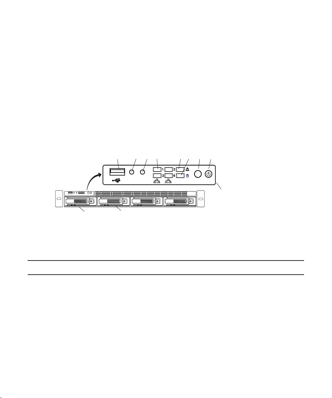
System Director Front Panel
The following figure shows the front view and control panel of the System Director.
System Director Front View
System Director
The following table describes the control panel shown in the previous figure.
System Control Panel
Letter Component Description
A Universal Serial Bus (USB) port USB 2.0 device port on the front of the system supports one USB device.
Recommended for use when re-imaging the system drives or loading
software. Two more USB ports are located on the back of the system.
B Halt or Non-maskable interrupt
(NMI) button
The halt or NMI signal halts the processor, which effectively halts the
server. An NMI is the highest priority interrupt and cannot be masked by
software.
If the Halt/NMI button is pressed, the NMI signal locks the
c
system and the system must be restarted to clear the interrupt.
16
Page 17
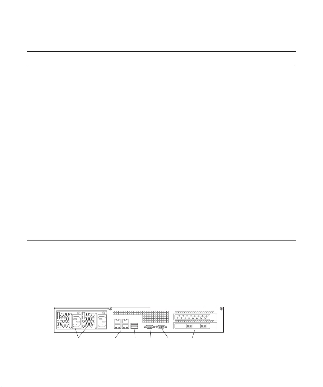
System Director
Power supplies
Serial 1 Gb Ethernet VideoUSB
10 Gb Ethernet
System Control Panel (Continued)
Letter Component Description
C System reset button Performs a soft reset when pressed. Do not use this button unless the
system has had a fatal error and you need to restart. A soft reset restarts
the system; it clears all active program memory (you lose unsaved work)
and shuts down all active programs.
D Four green network activity
LEDs
E Red System error LED Illuminates red when an error is detected with the system (fan, power
F System Drive activity LED Indicates drive activity from the onboard SATA controller and blinks
G System ID button When pressed it illuminates (blinks) blue and also illuminates an LED on
H Power button Press to turn on the enclosure. Power button illuminates green when the
Illuminates green when a good network connection is established and
blinks when there is network activity on the four built-in 1 GB network
ports.
The number beside the LED corresponds with the number beside the
network port on the rear of the enclosure. For example, Connector 1 is
LED 1 on the front; see
supply, temperature, voltage).
when either of the system drives is being accessed.
the rear of the enclosure. The rear LED is also blue and is visible on the
lower left-hand side of the Ethernet ports inside of the enclosure. It is
used to identify a system for servicing when it is installed in a
high-density rack/cabinet populated with several other similar systems.
power is on.
“System Director Rear Panel” on page 17.
System Director Rear Panel
The following figure shows the rear panel of the System Director and the function of each
connection. The System Director comes with a Myricom dual-port 10 Gb network board
installed in the System Director, and an SFP+ optical transceiver for the port.
System Director Rear View
17
Page 18

Second System Director
You can purchase a second System Director and configure it on the same subnets as the original
System Director. This provides a redundant System Director that is in constant contact with the
original System Director. The second System Director automatically takes over if the original
System Director fails (For more information see
page 92
).
Engine
The Engine is 5U (rack unit) in size and stores the data shared by the ISIS clients. Up to five
Engines are supported in the ISIS | 2500 environment providing 1.6 petabytes (PB) of raw
storage (1.2 PB usable storage). Avid ISIS | 2500 Engines are available in two configurations:
“ISIS | 2500-320 Media Drive Configuration” on page 25 and “ISIS | 2500-160 Media Drive
see
Configuration” on page 26
4 terabyte (TB) SAS drives. These media drives are configured for redundant array of
independent disks (RAID) 6 storage protection.
Engines can be configured as separate Storage Groups or be added to existing Storage Groups. If
you choose to add the new Engines to an existing Storage Group, the existing data is
redistributed to spread the data evenly across all drives in the Storage Group.
Engine
“Configuring System Director Failover” on
. Both models of Avid ISIS | 2500 Engines are populated with
The data flows to and from the Engine through the Engine Controller using a 10 Gb Ethernet
connection. Only the left connector (as seen from the rear of the Engine Engine Rear View) is
used to connect the Engine to the ISIS switch. This connection provides access to the data on
media drives to the System Director and clients. The 10 Gb Ethernet ports on both the switch and
Engine Control require SFP+ transceivers. For instructions on see
with a 10 Gb System Director Connection” on page 60
The Engine contains the following components:
• Engine Front View
• Engine Control Panel
•Engine Rear View
• Cooling Modules
•Power Supplies
Engine Front View
Each drawer in the Engine allows access to 42 drive slots. The number of media drives populated
in each drawer varies depending on your ISIS | 2500 Engine configuration (ISIS | 2500-320 or
ISIS | 2500-160). The first drive slot is located in the front-row, left-side of the top drawer and
“Connecting Network Cables
.
18
Page 19
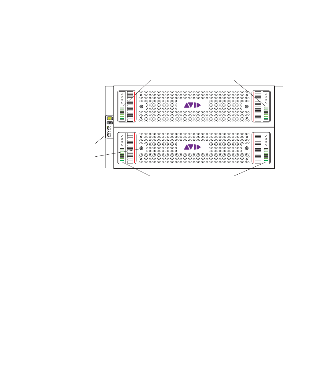
Engine
Tamper proof locks (x4)
Control panel
Drawer 1 status and activity indicators
Drawer 2 status and activity indicators
the last drive is in the last row on the far-right portion of the drawer. The second drawer is
ordered in the same way; left-to-right in each of the three rows starting in the front and ending in
the back right corner. For more information on the drive slot configuration, see “ISIS | 2500-320
Media Drive Configuration” on page 25
page 26
.
and “ISIS | 2500-160 Media Drive Configuration” on
n
Engine Control Panel
Each drive can be removed and replaced separately with the power on.
If you replace a drive with power on, the LEDs in all of the drives go off momentarily. This does
not represent a problem. All functions are still active and working properly.
The following figure shows the ISIS | 2500 Engine control panel.
19
Page 20
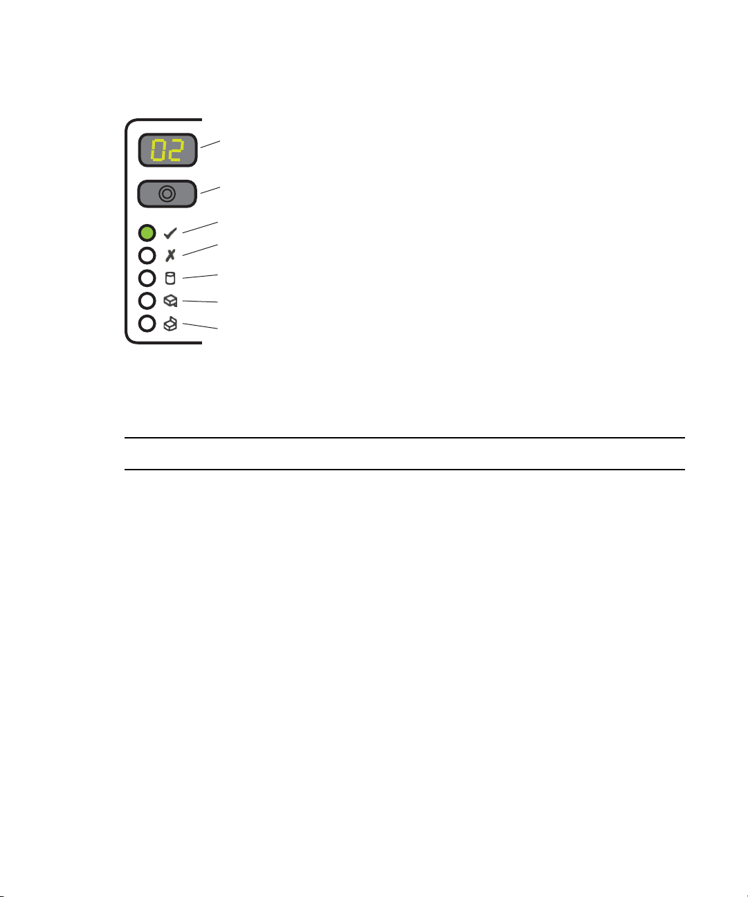
ISIS | 2500 Engine Front Panel
Unit ID display
Input switch
Power on / standby
Module fault
Logical status
Drawer 1 fault
Drawer 2 fault
The following table describes the control panel shown in the previous figure.
Engine Control Panel
Engine
Component Description
Unit ID Display Displays the unit number assigned to the Engine. When a signal is sent
from the software, the ID number blinks to identify the Engine. This
helps locate the Engine when it is installed in a high-density
rack/cabinet populated with several other similar systems.
Input Switch Press to turn on the enclosure.
Power on / Standby Indicator Illuminates green when the power is on. A power switch is located on
each of the two power supplies on the back of the Engine.
Module Fault Indicator Illuminates amber when an error is detected with the system. The
following are possible faults.
• On: with single beep, then double beep — power on test state.
• On: any power supply, voltage, fan, module, or temperature (over or
under) fault
• Flashing: logical fault — unknown, invalid, or mixed module type
installed, bus failure (inter communication failure), or EBOD VPD
configuration error.
• On: Drive failure causing loss of availability or redundancy
• Flashing: when both the Module Fault and Logical Status LEDs are
flashing, the unit ID number is different from “Start of Day.”
20
Page 21
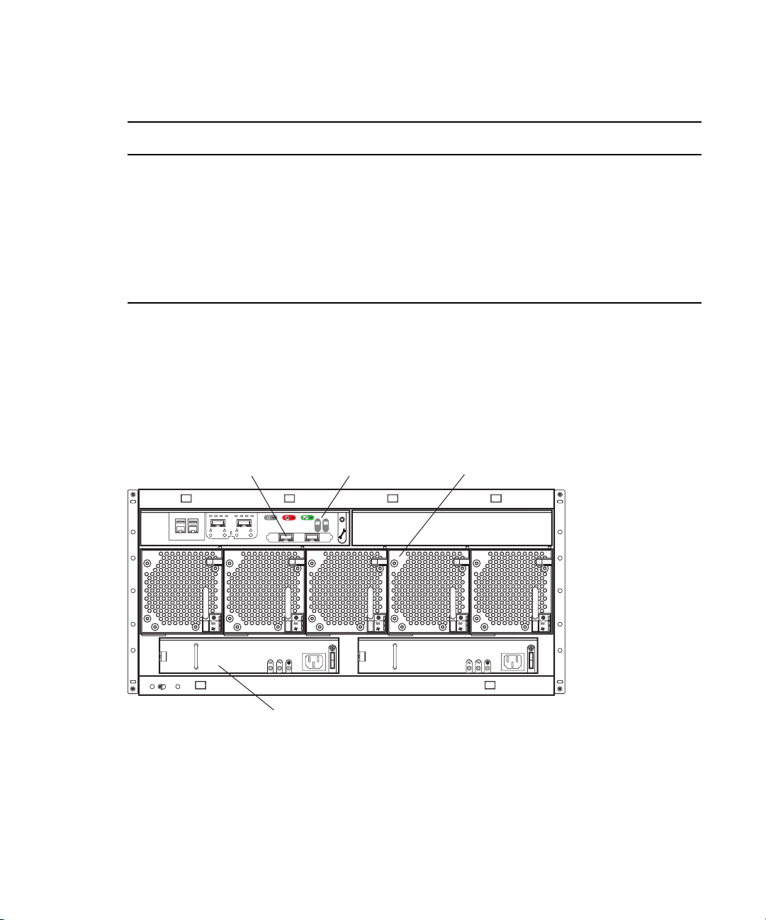
Engine Control Panel (Continued)
Engine Controller Cooling module (x5)
Power supply unit (x2)
10 Gb Connection
Component Description
Logical Status Indicator Flashes amber when arrays are performing a background function.
Drawer 1 Fault Indicator Illuminates amber when an fault is detected with a drive, cable, or fan in
Drawer 2 Fault Indicator Illuminates amber when an fault is detected with a drive, cable, or fan in
Engine Rear View
The following figure shows the rear of the Engine in a configuration that contains the following:
• One Engine Controller (only supported in the left slot as seen from the rear of the Engine)
• Five cooling Modules
• Two power supplies
Engine
When both the Module Fault and Logical Status LEDs are flashing, the
unit ID number is different from “Start of Day.”
the top drawer.
the bottom drawer.
Cooling Modules
Five cooling modules are turned on when the power supplies are on. They contain fans that cool
the system. The system needs only three of the five cooling modules to supply the needed
cooling for the Engine to function properly. You can remove and replace a cooling modules
while the system is running if one fails.
21
Page 22
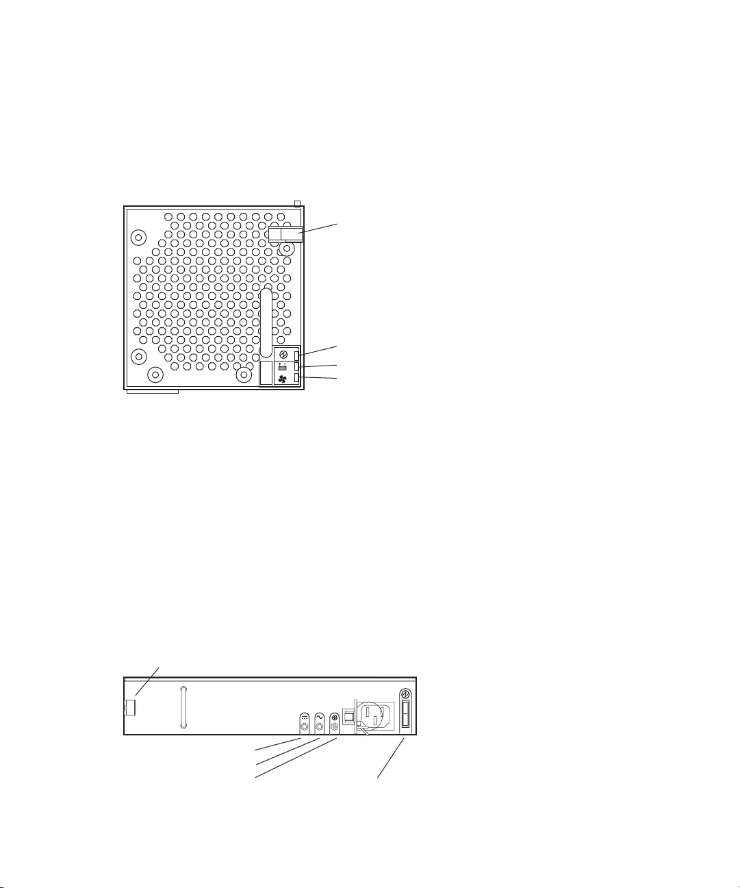
Engine
Release latch
Module OK
Battery fault
Fan fault
Release latch
Power OK
Power supply fault
AC fault
Power Switch
c
w
Leave failed modules in place until you have a replacement so you maintain the proper
airflow. Obtain a replacement as soon as possible.
Only trained Avid qualified service personnel should remove and replace modules while the
Engine is running. Since power to the Engine is still applied internally to the midplane,
always keep your hands outside the Engine when removing a module.
Power Supplies
The power supplies are turned on when the power cord is plugged in and the power switch is on.
The power supplies provide power and contain fans that cool the system. The system needs only
one of the two power supplies to supply the needed power to function properly. You can remove
and replace a power supply temporarily while the system is running if one fails.
c
w
Leave failed modules in place until you have a replacement so you maintain the proper
airflow. Obtain a replacement as soon as possible.
Only trained Avid qualified service personnel should remove and replace modules while the
Engine is running. Since power to the Engine is still applied internally to the midplane,
always keep your hands outside the Engine when removing a module.
22
Page 23

Storage Configurations
Engine Power Supply Panel
Component Description
Release Latch Displays the unit number assigned to the Engine. When a signal is sent
from the software, the ID number blinks to identify the Engine. This
helps locate the Engine when it is installed in a high-density rack/cabinet
populated with several other similar systems.
Power Supply Fault Indicator Illuminates amber when an error is detected with the system. The
following are possible faults.
• On: with single beep, then double beep — power on test state.
• On: any power supply, voltage, fan, module, or temperature (over or
under) fault
• Flashing: logical fault — unknown, invalid, or mixed module type
installed, bus failure (inter communication failure), or EBOD VPD
configuration error.
• On: Drive failure causing loss of availability or redundancy
• Flashing: when both the Module Fault and Logical Status LEDs are
flashing, the unit ID number is different from “Start of Day.”
AC Input Fault Indicator Flashes amber when arrays are performing a background function. When
both the Module Fault and Logical Status LEDs are flashing, the unit ID
number is different from “Start of Day.”
Power on / Standby Indicator Illuminates green when the power is on. A power switch is located on
each of the two power supplies on the back of the Engine.
Power Switch Press to turn on the enclosure.
Storage Configurations
Avid ISIS | 2500 Engines are populated with 4 terabyte (TB) SAS drives using parity protected
disk storage utilizing a RAID 6 (redundant array of independent disks, level 6) algorithm. The
ISIS | 2500-320 is a fully populated configuration with 82 media drives providing up to 256 TB
of usable storage after configuring the RAID set.
The ISIS | 2500-160 is populated with 42 drives in two drawers, providing up to 128 TB of
usable storage after configuring the RAID set.
23
Page 24

Storage Group Size
An ISIS | 2500-160 Engine provides one Storage Manager, and the ISIS | 2500-320 has two
Storage Managers. The Storage Manager is used to create one or two Storage Groups in the ISIS
file system (one or two Storage Groups per Engine). The media drives in each Engine are bound
into Storage Groups. A fully populated ISIS | 2500-320 Engine can be bound into one or two
Storage Groups or you can combine multiple Engines as a single Storage Group.
If you have Engines configured as a single Storage Group and want to make two Storage Groups,
you must delete the Storage Group and create two new Storage Groups. Data is stored in the
Storage Group in 4 MB chunk sizes. You cannot change the chunk size of a Storage Group.
Storage Configurations
c
RAID-6 Storage Groups, Single Drive
RAID-6 Storage Groups, Dual Drive Failure
When you delete the Storage Group all data on the Storage Group is lost.
When there is a single drive failure in an ISIS Storage Group configured with RAID protection,
the Storage Group continues to function normally at a lower bandwidth.
When a drive fails, the rebuild is started automatically by the RAID solution.
An “unprotected state” occurs when two drives fail in a RAID-6 Storage Group. In an
unprotected state with no additional failures, read operations continue to function normally at a
lower bandwidth.
It is highly recommended that you replace any failed drives immediately, to create new hot
spares for possible future drive failures. This ensures full protection of all stored data at the
earliest possible time.
Drive Array and Slot Locations
Avid ISIS | 2500 Engines are available in two configurations; both configurations are populated
with 4 TB SAS drives. These media drives are configured for redundant array of independent
disks (RAID) 6 storage protection.
New installations are created using a common slot configuration. However, once a disk has
failed, the initial layout changes and the default configuration no longer applies. The numbers
assigned to the slots and the group numbers are not displayed in the ISIS software.
24
Page 25

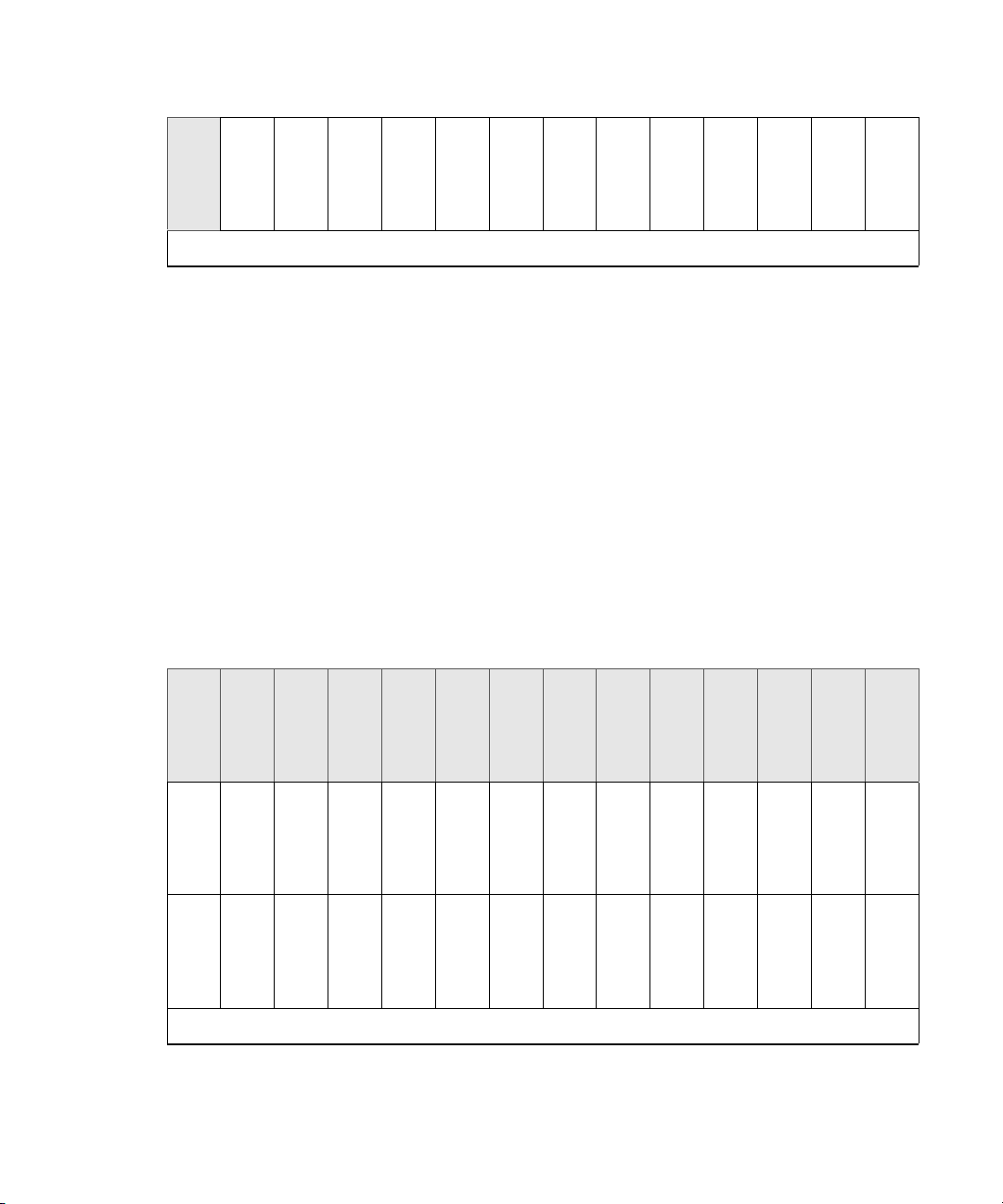
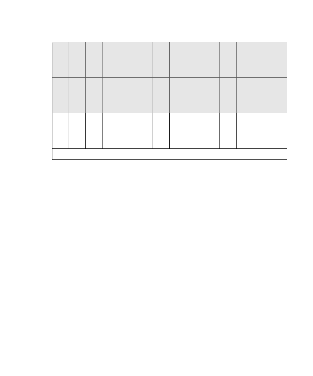
ISIS | 2500-320 Media Drive Configuration
The ISIS | 2500-320 has 82 media drives with two drives reserved as hot spares. The drives are
configured into eight RAID 6 groups (10 drives in each group) in each Avid ISIS | 2500-320
Engine. The hot spares are automatically used whenever a RAID set detects a degraded drive.
This results in continued access to your workspace data with no data loss during the failure and
repair.
Storage Configurations
c
The spare drives are created at the end of the last RAID group in bottom drawer when the
RAID groups are initially configured. Once a drive group has used a spare drive and a new
spare is established, the original configuration no longer applies.
320 TB, Drawer 1 (Top) — Initial Media Drive Slot Locations and RAID Groups
Drive Slot 28
Drive Slot 29
Drive Slot 30
Drive Slot 31
Drive Slot 32
Drive Slot 33
Drive Slot 34
Drive Slot 35
Drive Slot 36
Drive Slot 37
Drive Slot 38
Drive Slot 39
Drive Slot 40
Drive Slot 41
Drive Slot 14
Drive Slot 15
Drive Slot 16
Drive Slot 17
Drive Slot 18
Drive Slot 19
Drive Slot 20
Drive Slot 21
Drive Slot 22
Drive Slot 23
Drive Slot 24
Drive Slot 25
Drive Slot 26
Drive Slot 27
Drive Slot 0
Empty
Drive Slot 1
Drive Slot 2
Drive Slot 3
Drive Slot 4
Drive Slot 5
Drive Slot 6
Drive Slot 7
Drive Slot 8
Drive Slot 9
Drive Slot 10
Drive Slot 11
Drive Slot 12
Drive Slot 13
Top Drawer — Front
320 TB, Drawer 2 (Bottom) — Initial Media Drive Slot Locations and RAID Groups
Drive Slot 70
Drive Slot 56
Drive Slot 71
Drive Slot 57
Drive Slot 72
Drive Slot 58
Drive Slot 73
Drive Slot 59
Drive Slot 74
Drive Slot 60
Drive Slot 75
Drive Slot 61
25
Drive Slot 76
Drive Slot 62
Drive Slot 77
Drive Slot 63
Drive Slot 78
Drive Slot 64
Drive Slot 79
Drive Slot 65
Drive Slot 80
Drive Slot 66
Drive Slot 81
Drive Slot 67
Drive Slot 82
Drive Slot 68
Drive Slot 83
Drive Slot 69
Page 26
Drive Slot 42
Empty
Drive Slot 43
Drive Slot 44
Drive Slot 45
Drive Slot 46
Bottom Drawer — Front
ISIS | 2500-160 Media Drive Configuration
The ISIS | 2500-160 has 42 media drives with two drives reserved as hot spares. The drives are
configured in the Avid ISIS | 2500-160 Engine as four RAID 6 groups (10 drives in each group).
The hot spares are initially created in the bottom drawer and are automatically used whenever a
RAID set detects a degraded drive. This allows for continued access to your workspace data with
no data loss during the failure and repair.
Drive Slot 47
Drive Slot 48
Drive Slot 49
Drive Slot 50
Drive Slot 51
Storage Configurations
Drive Slot 52
Drive Slot 53
Drive Slot 54
Drive Slot 55
c
c
The spare drives are created in the bottom drawer when the RAID groups are initially
configured. Once a drive group has used a spare drive and a new spare is established, the
original configuration no longer applies.
When replacing a failed media drive, you must install the replacement drive in the slot
where you removed the failed drive. Do not install replacement drives in the slots identified
as “Not Used” in the following illustrations.
160 TB, Drawer 1 (Top) — Initial Media Drive Slot Locations and RAID Groups
Not Used
Not Used
Not Used
Not Used
Not Used
Not Used
Not Used
Not Used
Not Used
Not Used
Not Used
Not Used
Not Used
Not Used
Drive Slot 14
Drive Slot 15
Drive Slot 16
Drive Slot 17
Drive Slot 18
Drive Slot 19
Drive Slot 20
Drive Slot 21
Drive Slot 22
Drive Slot 23
Drive Slot 24
Drive Slot 25
Drive Slot 26
Drive Slot 27
Drive Slot 0
Drive Slot 1
Drive Slot 2
Drive Slot 3
Drive Slot 4
Drive Slot 5
Drive Slot 6
Drive Slot 7
Drive Slot 8
Drive Slot 9
Drive Slot 10
Drive Slot 11
Drive Slot 12
Drive Slot 13
Top Drawer — Front
26
Page 27
160 TB, Drawer 2 (Bottom) — Initial Media Drive Slot Locations and RAID Groups
Bottom Drawer — Front
Clients
Not Used
Not Used
Drive Slot 42
Not Used
Not Used
Drive Slot 43
Not Used
Not Used
Drive Slot 44
Not Used
Not Used
Drive Slot 45
Not Used
Not Used
Drive Slot 46
Not Used
Not Used
Drive Slot 47
Not Used
Not Used
Drive Slot 48
Not Used
Not Used
Drive Slot 49
Not Used
Not Used
Drive Slot 50
Not Used
Not Used
Drive Slot 51
Not Used
Not Used
Drive Slot 52
Not Used
Not Used
Drive Slot 53
Not Used
Not Used
Drive Slot 54
Clients
Not Used
Not Used
Drive Slot 55
The Avid ISIS | 2500 systems support 200 ISIS clients using either 1 Gb, dual 1 Gb, or 10 Gb
connections at any client type setting. The client communicates with the drives through the
switch to create, modify, and read files stored in the actual drive.
A client uses mechanisms specific to the operating system to display, create, and delete files
within the Avid ISIS shared storage network system. For example, when viewed from a
Windows operating system, the system sees a server containing many shares that are mapped to
drive letters.
CIFS and FTP Clients
The ISIS | 2500 also includes a File Gateway providing unlimited Common Internet File System
(CIFS) clients, without using Avid ISIS client licenses. This client connection enables network
users to access the ISIS Workspaces in a non-realtime scenario. Depending on the access
permission, network users can read, write, and delete files on Workspaces without using ISIS
client licenses. For instructions on setting up CIFS clients see the Avid ISIS File Gateway Setup
and User’s Guide.
27
Page 28

Only System Directors with a 10 Gb connection to the switch support CIFS and FTP clients.
n
When using a 1 Gb connection between the ISIS | 2500 System Director and the switch, you must
turn off the CIFS service after you have installed the ISIS | 2500 software. See “Turning Off the
CIFS Service With a 1 Gb Connected System Director” on page 89.
A client uses mechanisms specific to the operating system to display, create, and delete files
within the Avid ISIS shared storage network system. For example, when viewed from a
Windows operating system, the system sees a server containing many shares that are mapped to
drive letters.
You can also configure the System Director to share ISIS Workspaces over the network using the
File Transfer Protocol (FTP) function controlled by the Microsoft’s Internet Information
Services (IIS) and the FTP Service. For instructions on setting up FTP clients see the Avid ISIS
File Gateway Setup and User’s Guide.
Network Zone Configurations
All clients in the shared storage network are classified by zones, depending on how they connect
to the network. The following list defines the clients in each network layer by their zone
classification:
Network Zone Configurations
ISIS | 2500 systems typically are integrated with ISIS | 7500 - 7000 or ISIS | 5500 - 5000
n
environments. The ISIS | 2500 System Director and ISIS | 2500 Engine are connected to ISIS |
7500 - 7000 or ISIS | 5500 - 5000 switches that have been configured with a separate VLAN for
the ISIS | 2500 components. See your site network administrator for assistance with configuring
the separate VLAN on your switch.
• Zone 1 Client — No Zone 1 client connection is available in ISIS | 2500 (direct connect to
ISIS | 2500 Engine)
• Zone 2 Client — Connected to ISIS VLANs via a 1 Gb or 10 Gb port on an Avid qualified
layer-2 switch (non-routed)
• Zone 3 Client — Connected to an Avid qualified layer-3 switch (routed) with known Quality
of Service (QoS); traffic routed to ISIS (one hop) and load-balanced across ISIS VLANs
(approximately a 60/40 ratio)
• Zone 4 Client — Connected to the house network using an edge or a core switch with
unknown QoS; traffic routed to Avid ISIS (measured by the number of hops) and
load-balanced across ISIS VLANs (approximately a 60/40 ratio)
Support for different client and device types varies by zone:
• Zone 1 — Not applicable
• Zone 2 — AirSpeed, editors, Interplay
28
Page 29
• Zone 3 — Instinct, Assist, certain editors
VLAN
Zone 2
Intel Pro 1000
PT board
Client systems
in Zone 2
1 Gb or 10 Gb Ethernet
10 Gb Ethernet
Zone 2 switch with
1-Gb and 10-Gb Ports
Engine
System Director
• Zone 4 — Instinct, Assist; typical formats include DV25, MPEG-2 proxy (2 Mb/s)
The following four examples show different types of Avid ISIS configurations.
Zone 1 Clients (Direct Connected)
The ISIS | 2500 does not provide any client connections directly to the Engine or System
Director. Client connections are only available through a switch.
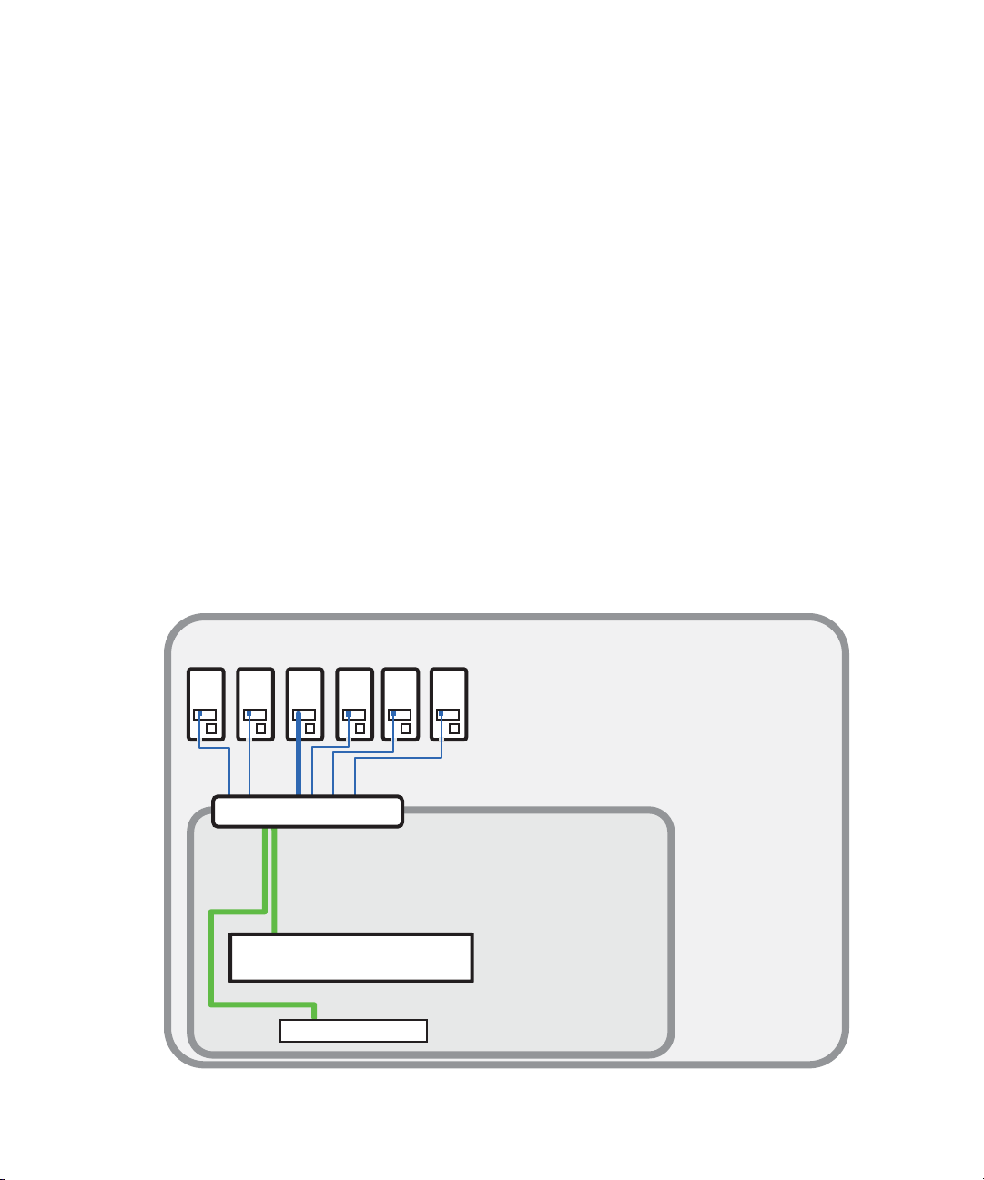
Zone 2 Clients (Indirect Connect) Configuration
Clients that are connected to a switch are referred to as Zone 2 clients. Zone 2 clients are not
routed. For a list of supported switches, see the Avid ISIS ReadMe.
A Zone 2 configuration consists of a group of clients, connected to an Ethernet switch with a 10
Gb port connected to the ISIS | 2500 Engine. The System Director also connects to the switch
using a 1 Gb port or 10 Gb port. Each client connects to the ISIS switch using either a 1 Gb or
10 Gb connection.
Avid ISIS Zone 2 Network Configuration
Network Zone Configurations
29
Page 30

Zone 3 and Zone 4 Client Configuration
A Zone 3 (indirect connect) configuration consist of a group of clients, connected to an Avid
qualified layer-3 switch (routed), with known Quality of Service (QoS); traffic routed to ISIS
(one hop) and load-balanced across ISIS VLANs (approximately a 60/40 ratio).
A Zone 4 (indirect connect) configuration consists of a group of clients, using an Ethernet switch
with unknown QoS; traffic routed to Avid ISIS (measured by the number of hops) and
load-balanced across ISIS VLANs (approximately a 60/40 ratio).
The house switch must have uplinks to the Avid Production Network through an Ethernet switch
that contains a 10 Gb port connected to the Engines. The ISIS | 2500 System Director also
connects to the switch using a 1 Gb port or 10 Gb port. The ISIS | 2500 can connect to the same
APN switches as the primary ISIS | 7500 - 7000 or ISIS | 5500 - 5000, but must use a different
subnet from the other ISIS storage systems.
Network Zone Configurations
30
Page 31

Avid ISIS Zone 3 and Zone 4 Network Configuration
Zone 4
Zone 3
House switch
Zone 3 client
routed VLAN 40
Zone 4 clients
corporate network
ISIS 7000
Client systems
in Zone 1
Chassis
interconnect
ISS VLAN 10
ISS VLAN 20
Engine
Engine
System Director
ISS VLAN 20ISS VLAN 10
System Director
Zone 2
Avid Production Network (Zone 1, 2, and 3)
1 Gb Ethernet
VLAN 10 VLAN 20
VLAN 40
Zone 3 layer 3 switch
(Layer 3 routed/switched)
VLAN 10 VLAN 20
Zone 2 Layer 2 switch
(Layer 2 switched)
Can be one
multilayer switch
(Layer 3 routed/switched)
Zone 1
System Director
10 Gb Ethernet
ISIS 2000
VLAN
Zone 2 clients
VLAN 30
Engine
Engine
Engine
System Director
Cabling
Cabling
For a list of cables qualified with the Avid ISIS system, see “Supported Cabling” on page 162.
31
Page 32

2 Connecting the ISIS Equipment
This chapter explains how to rack mount and connect the system hardware. A system installation
check list is provided to help you perform the installation in the correct order. The check list
contains references to information in this and other chapters in this document or the ReadMe file
to complete the installation.
For information on connecting and configuring two System Directors for failover, see
n
“Configuring System Director Failover” on page 92.
Rack Mounting the Equipment
This chapter describes how to install and connect the System Director and other workgroup
hardware.
c
Rack Mounting Example
For information about power specification and dimensions see “Specifications and Notices”
on page 160.
The following example shows a typical ISIS | 2500 rack configuration with a System Director
and Engine.
Page 33
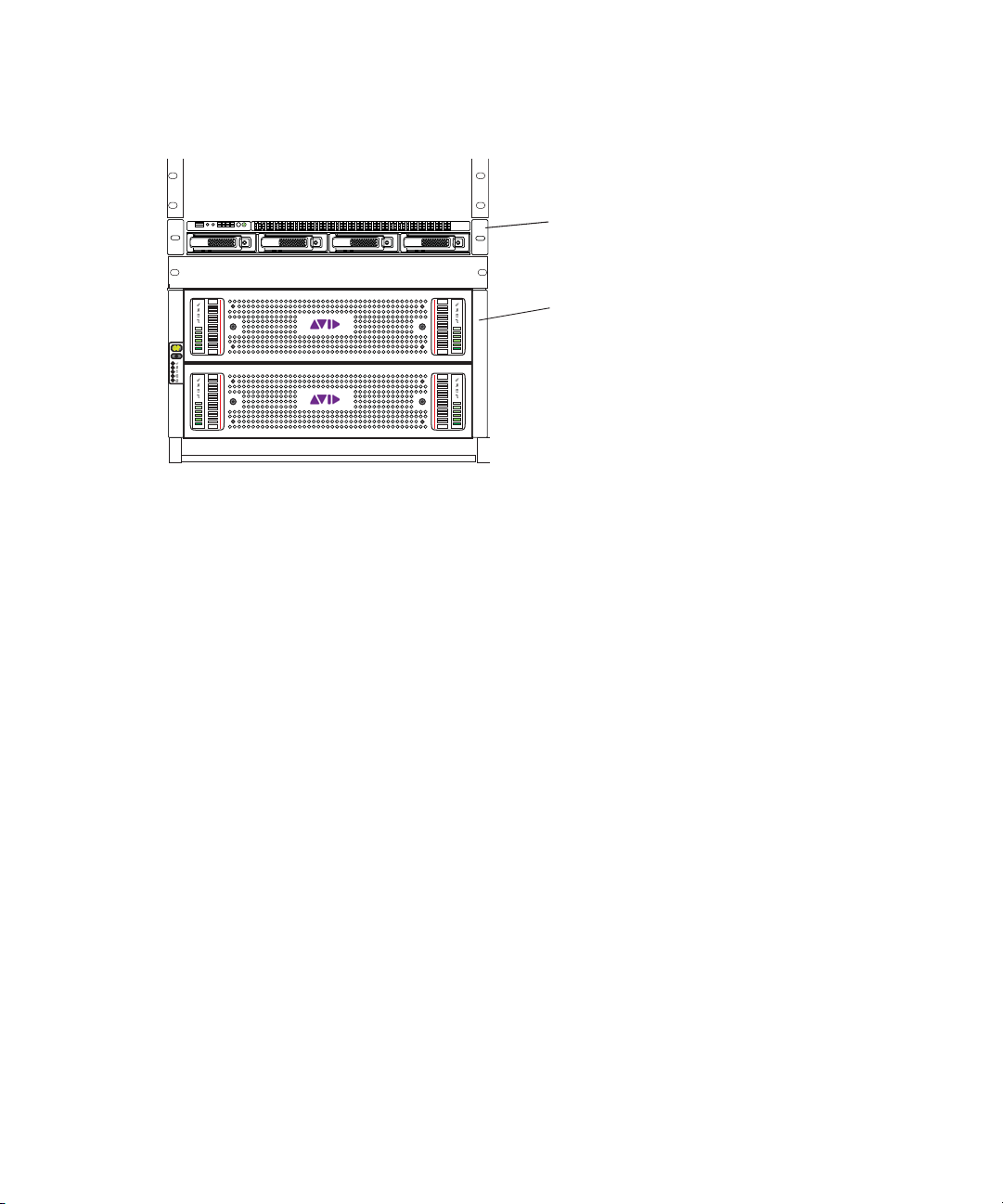
ISIS | 2500 System Director and Engine
System Director
1 rack unit
ID
ISIS 2000 Engine
5 rack units
Installing Rack-Mounted Rails and Brackets
The System Director is designed for 19-inch (483-mm) rack configurations and requires one EIA
rack units (1U), or 1.75 inches (44.45 mm) of rack space. The rail kit installs into rails that are
between 23-inches (584.2-mm) to 31-inches (787.4-mm) inches deep. An optional rail kit is
available for racks that are up to 37 inches deep.
Rack Mounting the Equipment
The System Director includes rack-mounting slide rails. If instructions are included with your
rail kit, use them instead of the instructions included in this section. The standard rail
configuration is for racks with square mounting holes. Optional brackets are included for racks
with threaded holes. The rack-mounting kit requires inner slide rails be mounted to the server
and the outer slide rails are mounted to the rack. Once both the inner and outer rails are in place,
slide the server with the inner rails attached into the outer rails. Secure the server in the front of
the rack using the supplied screws so it does not slide forward.
c
w
The System Director is designed to be installed horizontally in a rack. Installing the System
Director on an angle or in a sloped console causes the internal drives to wear faster than
the intended life of the drive.
To ensure the stability of the rack enclosure, install the heaviest equipment in the lower
sections of the rack enclosure. Install lighter equipment in the middle and upper sections.
33
Page 34

Review the following recommendations before rack mounting Avid ISIS equipment:
• Avid recommends that you leave a 1U or half-U space between each piece of equipment
mounted in the racks. This allows for better airflow and cable access, and helps stop
vibration in any equipment being transferred to spaces above and below.
The 1U System Director has vent holes on the top of the enclosure. Avid has performed thermal
n
testing with the top vent holes blocked, and the results indicated that even with the top vent holes
blocked, the 1U System Director still operates within the temperature tolerances.
• Avid recommends that you leave an 8 to 12 inch space empty beneath the lowest piece of
equipment installed in the rack. This allows for better airflow and lowers the possibility of
dust or dirt being picked up by the devices.
• For normal operation, maintain approximately 2 feet (0.6 meters) of open space in front of
and behind the rack. This allows free access to the components in the rack for operating
changes or adjustments. For service, maintain approximately 3 feet (1 meter) of open space
in front of the rack and 2 feet (0.6 meters) of open space behind the rack. This allows for the
removal of any component that needs to be replaced.
Rackmount Requirements
• Elevated Operating Ambient — If installed in a closed or multi-unit rack assembly, the
operating ambient temperature of the rack environment might be greater than room ambient.
Make sure the rack environment is compatible with the maximum ambient temperature
(Tma) specified by the manufacturer.
Rack Mounting the Equipment
• Reduced Air Flow — When installing equipment in a rack, make sure not to block the
amount of air flow required for safe operation.
Avid ISIS airflow is from the front of the enclosure to the rear. Make allowances for cooling
air to be available to the front panel surface and no restrictions at the rear.
• Mechanical Loading — Avoid uneven mechanical loading.
Make sure your rack enclosure is stable enough to prevent tipping over when one or more
Avid ISIS servers are extended on the sliding rails.
• Circuit Overloading — Follow the equipment nameplate ratings to avoid overloading the
circuits.
• Reliable Grounding — Maintain reliable grounding of rack-mounted equipment, especially
regarding supply connections other than direct connections to the branch circuit (for
example, power strips).
• Inside Enclosure Access — Allow at least 0.5 in (1.3 cm) clearance on top of the enclosure
for cover removal.
34
Page 35
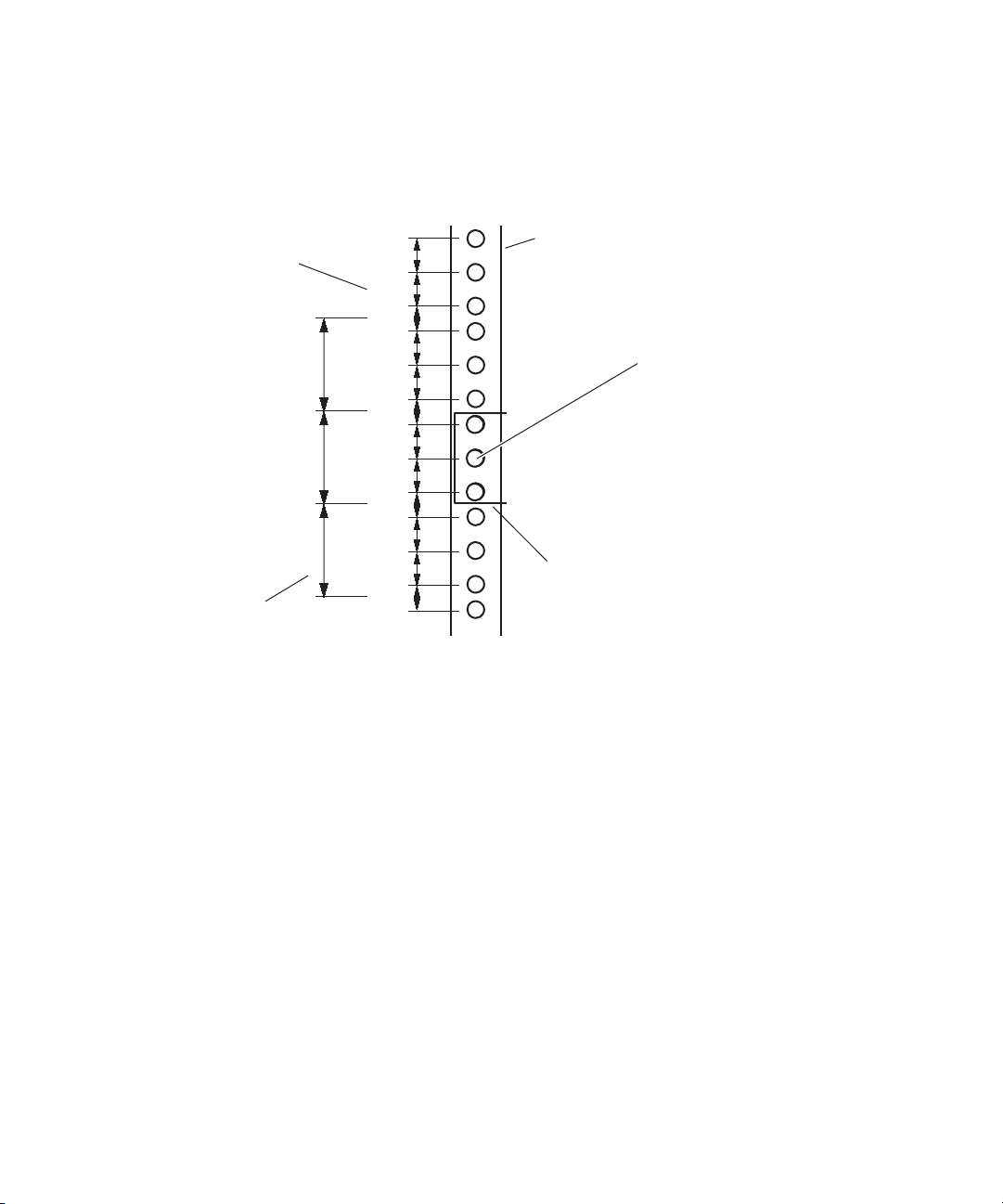
Positioning the System Director in the Rack
5/8 in
5/8 in
1/2 in
5/8 in
5/8 in
1/2 in
5/8 in
5/8 in
1/2 in
5/8 in
5/8 in
1/2 in
1U
2U
3U1 3/4 in
1 3/4 in
1 3/4 in
Baseline position is between
two 1/2inch holes.
Rack mounting rail
hole spacing
EIA rack unit
Rack mounting rail
System Director
front panel mounting hole
Use the following figure to help you decide where to install the System Director in the rack.
Select a position where the System Director is at the proper baseline.
Rack Mounting the Equipment
Separating the Slide Rails
Separate the slide rails and attach the inner “movable” section to the System Director and the
outer “fixed” section to the rack rails.
To separate the slide rails:
1. Slide the slide rail completely open.
2. Press the spring clip on the inner slide rail as shown in the illustration.
The spring clip shown in the following illustration is on the bottom side of the slide rail.
n
35
Page 36
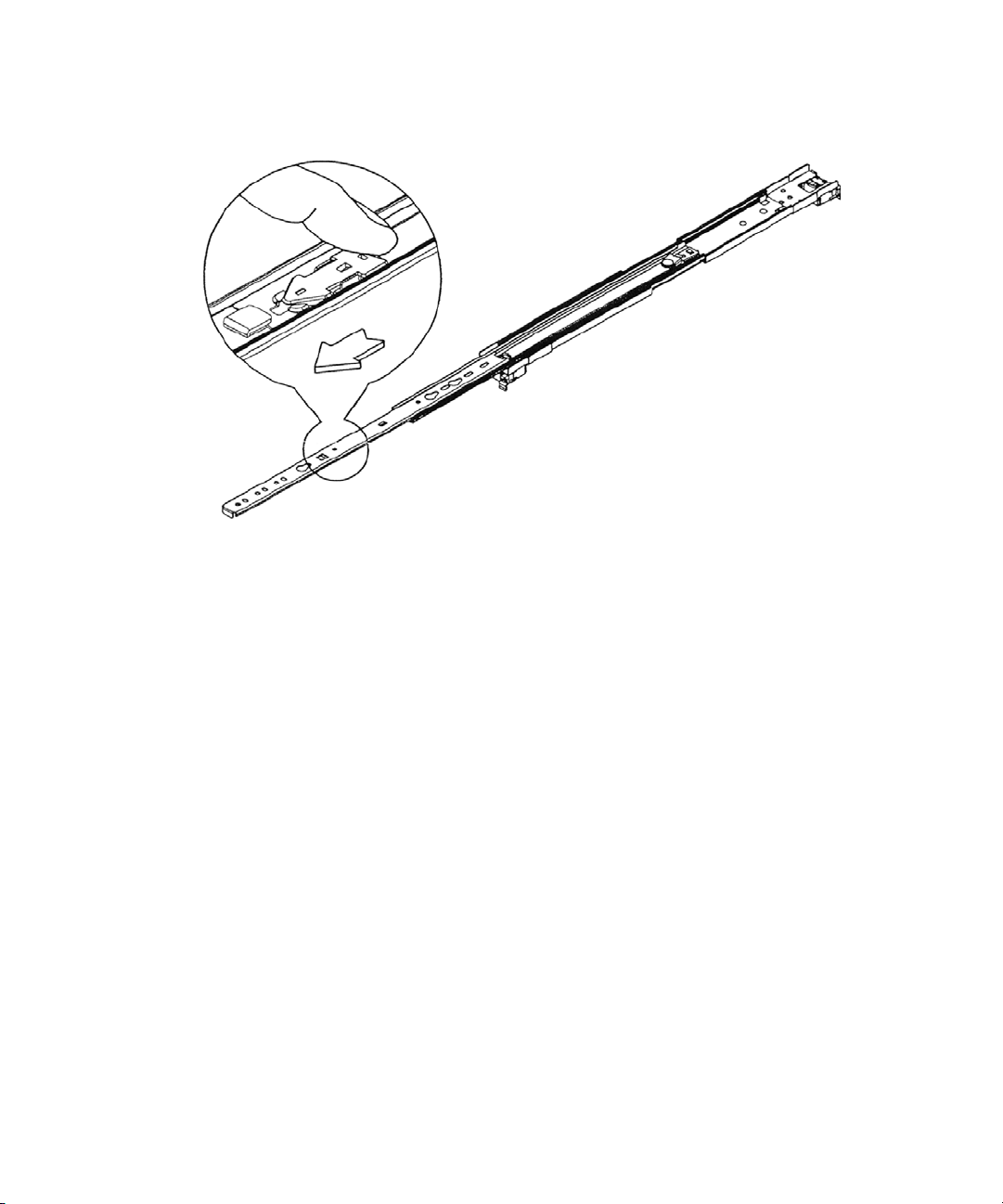
Separating the Slide Rails
3. Pull and separate the two halves.
Rack Mounting the Equipment
4. Repeat these steps to separate the second slide rail.
Attaching Inner Slide Rails to the System Director
Attach the inner slide rails that were separated from the outer slide rails to the System Director.
To attach the inner slide rails:
1. Position the inner slide rail against the side of the server so that the screw holes are toward
the rear of the server, and front of the slide rail fits over the tab at the front of the server.
2. Secure the inner slide rail to the server with two of the small screws.
The rail kit might contain more screws than needed.
n
36
Page 37
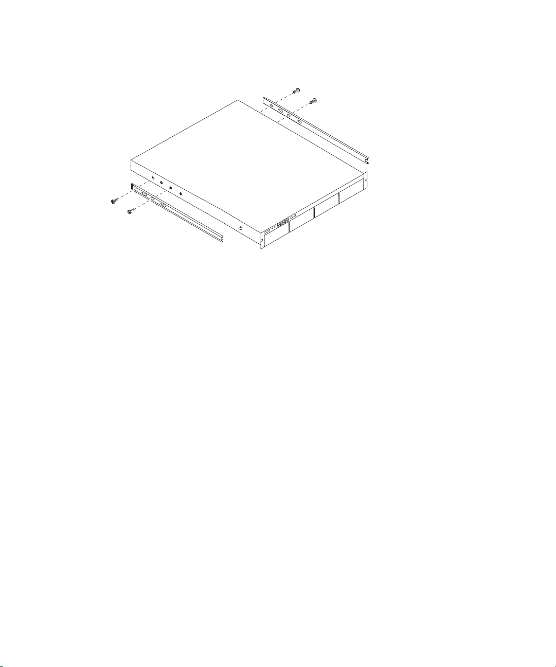
Attaching the Inner Slide Rails
3. Repeat this procedure to attach the other inner slide rail on the other side of the server.
Attaching the Outer Rails to a Square-Hole Rack
After separating the slide rails as previously described (see “Separating the Slide Rails” on
page 35
“Attaching the Outer Rails to a Threaded-Hole Rack” on page 39.
), perform the following procedure. If your mounting rails have threaded holes, see
Rack Mounting the Equipment
To attach the outer slide rails to the rack with square holes:
1. Align the outer slide rail bracket assembly with the front rack-mounding holes.
Have someone help you hold the slide rails level while you position them in the rack.
n
2. Slide the square tabs through the holes in the front, vertical rack mounting rail.
37
Page 38
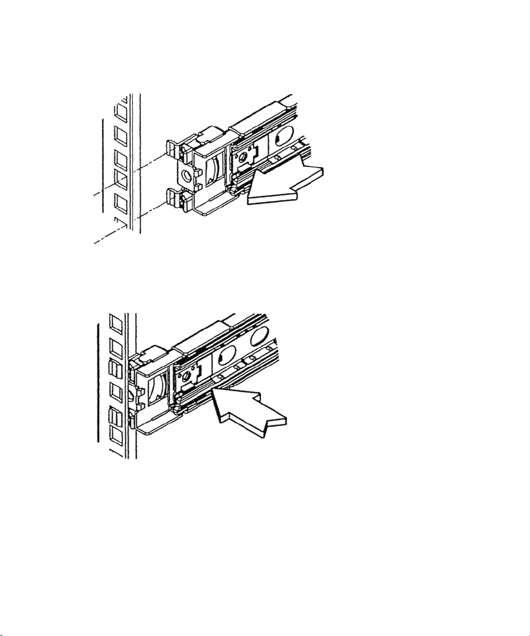
Rack Mounting the Equipment
Positioning the Outer Slide Rail with the Front Rack-Mounting Rail
3. Push the outer rail towards the outside of the rack, to secure the outer rail in place
Insert the Outer Slide Rail to the Front Rack-Mounting Rail
4. Adjust the outer slide rail bracket assembly to the rear mounting rail.
5. Secure the rear outer slide rail bracket assembly to the rear mounting rail as you did for the
front rack-mounting rail.
38
Page 39

Securing the Outer Slide Rail to the Rear Rack-Mounting Rail
Round hole adapter
Outer slide rail bracket assembly
Bracket assembly tabs
6. Repeat this procedure to attach the second outer slide rail on the other side of the rack.
Attaching the Outer Rails to a Threaded-Hole Rack
Rack Mounting the Equipment
After separating the slide rails as previously described (see “Separating the Slide Rails” on
page 35
), perform the following procedure. If your mounting rails have threaded holes, clip on
the threaded hole adapter.
To attach the outer slide rails to the rack with threaded holes:
1. Locate the four threaded hole adapters (found in the accessory kit's plastic bag, not in the
rack mount kit box) and position the adapter on the end of the outer slide rail bracket
assembly as shown in the following illustration.
Attaching the Threaded Hole Adapter to the Bracket Assembly
39
Page 40
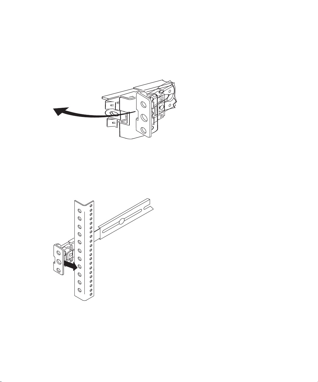
Rack Mounting the Equipment
2. With the bracket assembly tabs aligning with the cut-out in the threaded hole adapter, swing
the adapter so that the holes face the front of the bracket assemble as shown in the following
illustration.
Positioning the Threaded Hole Adapter
3. Slide the outer slide rail bracket assembly onto the side rack-mounting rail so that the
threaded hole adapter is over the rack rail.
Have someone help you hold the slide rails level while you position them in the rack.
n
Insert the Outer Slide Rail to the Front Rack-Mounting Rail
4. Insert the small (10-32) Phillips-head screws through the threaded-hole adapter and
mounting rail into the bracket. If the rack holes are different size, you must supply the
screws.
40
Page 41

Rack Mounting the Equipment
Securing the Outer Slide Rail to the Rack-Mounting Rail
5. Adjust the outer slide rail bracket assembly to the rear mounting rail.
6. Secure the rear outer slide rail bracket assembly to the rear mounting rail as you did for the
front rack-mounting rail.
7. Repeat this procedure to attach the second outer slide rail on the other side of the rack.
Securing the System Director in a Rack
Have someone help you hold the System Director while you position it in the rack.
n
To secure the server to the rack enclosure:
1. Lift and position the server so that the inner slide rails (secured to the System Director) are
aligned with the outer slide rails secured to the rack.
2. Push the front of the System Director server flush against the front mounting rail. The holes
in the server front panel align with the holes in the front mounting rail.
3. From the front of the rack enclosure, insert the large Phillips-head screw through the System
Director and front mounting rail.
- Square hole racks — the middle hole of the outer rail kit is where the screw anchors the
server front panel to the vertical rail. A M6x10 screw in the parts kit is included to
secure the front panel with square hole racks.
- Threaded hole racks — the server front panel attaches to the vertical rail of the rack. Use
a truss head screw or hardware that come with your rack to secure the front panel with
threaded hole racks.
41
Page 42

Front Panel Screws
Rack enclosure
front mounting rail
Mounting the Engine
The ISIS | 2500 Engine is designed for 19-inch (483-mm) rack configurations and requires five
EIA rack units (5U), or 8.75 inches (222.25 mm) of rack space. The ISIS | 2500 rack mount rails
are designed for racks with square or threaded holes. This procedure focuses on racks with
threaded holes. Additional instructions are included on a decal located on the side of one of the
bracket rails.
Rack Mounting the Equipment
n
w
Do not lift the Engine by the handles on the power supply units, cooling modules or Engine
Controllers – they are not designed to take the weight.
Lifting the Engine with the drives, cooling modules, and power supplies installed can cause
an injury. Before lifting the Engine, remove all modules and drives. Avid recommends that
two people be used whenever lifting the empty Engine.
42
Page 43

Rack Mounting the Equipment
Slide adjustment screws
Round pegs
Bracket rail
Rack mount screws
Bracket rail
Rack enclosure
Mounting rails
To mount the Engine into the rack:
1. (Option) If using racks with threaded holes, unscrew and remove the five round pegs on each
end of the bracket rail.
2. Loosen the four slide adjustment screws so to adjust the bracket rail to the depth of your
rack.
3. Position the bracket rail between your rack mount rails and adjust the length of the bracket
The adjustment screws are highlighted in a colored circle around the screw.
so that it meets the inside of both the front and rear rails as shown in the following figure.
43
Page 44

Rack Mounting the Equipment
4. Secure the bracket rail to the front and rear mounting rails using either the screws that come
with the rack mount kit of your rack screws (five screws in the front and the rear).
Leave the top holes on the front of the rail empty so you can use those holes to secure the Engine
n
to keep it from sliding forward once racked.
5. Tighten the four slide adjustment screws.
6. Repeat steps 1 through 5 to install the other bracket rail on the opposite side of the rack.
7. Make sure that the media drives are not installed in the Engine.
8. Using two people, lift the Engine and place the rear of the Engine onto the brackets as shown
in the following figure.
9. Position the bracket extender on the outside of the rear mounting rail so that the sliding nut
in the bracket extender inserts into the rack mounting tab on the Engine. Using the short
screws included in the rack mount kit, secure the bracket extender to the rack mounting tab
on the Engine as shown in the following figure.
The rack mount kit provides two sets of bracket extenders: a long pair and short pair. Use the
pair of bracket extenders that are most appropriate for your rack. For shallower racks use the
longer bracket extenders.
44
Page 45

Rack Mounting the Equipment
Bracket extender
Rack mounting tab
Sliding nut
Plastic covers
Plastic end caps
10. Using the screws from the rack mount kit, secure the Engine to the front of the rack through
top and bottom holes of the plastic end caps as shown in the following figure.
45
Page 46

Opening and Closing the Media Drive Drawers
11. Using the screws from the rack mount kit or screws you supply, secure the rear stabilizer
brackets to the rear rack mount rails through top and bottom holes in the extender bracket as
shown in the preceding figure.
12. Snap the left and right plastic covers over the plastic end caps on the front Engine as shown
in the preceding figure.
Opening and Closing the Media Drive Drawers
This section covers how to open the media drive drawer and replace a media drive. The
procedure is the same for both drawer 1 and drawer 2.
w
To ensure the stability of the rack enclosure, the Engine includes a mechanism that only
allows one drawer to be open at a time. If both drawers were open at the same time, the
rack could tip.
To open a drive drawer:
1. Make sure the anti-tamper locks are not engaged. The red arrows on the locks point inwards
if the locks are disengaged. Unlock them if necessary by rotating them counterclockwise
using a screwdriver with a Torx T20 bit.
2. Push the drawer latches inward and hold them.
3. Slowly pull the drawer all the way out until it locks open.
46
Page 47

To close a drive drawer:
Opening and Closing the Media Drive Drawers
n
c
1. Pull and hold both of the white latches on the sides of the drawer.
You might need to pull the drawer completely open before pulling the white latches.
2. Push the drawer in slightly.
3. Release the white latches.
4. Slowly push the drawer all the way back into the Engine, making sure it clicks in place.
Do not push the drawer in hard or slam it shut to avoid damaging the drives or the drawer.
47
Page 48

Installing the Media Drives
Installing the Media Drives
The procedure for installing the media drives is the same for both drawer 1 and drawer 2, but the
drives are installed in different locations depending on the Engine configuration:
• ISIS | 2500-320 Media Drive Configuration (1 Engine, with 82 drives) — 41 drives in each
drawer.
• ISIS | 2500-160 Media Drive Configuration (1 Engine, with 42 drives) — 28 drives installed
in the front slots of the top drawer, and 14 drives installed in the front slots of the bottom
drawer.
c
The ISIS | 2500-160 media drive configuration is mandatory. You must install the drives in
the slots specified. This is an air-flow requirement and is enforced with the software.
To insert a media drive:
1. Make sure the anti-tamper locks are not engaged. The red arrows on the locks will point
inwards if the locks are disengaged. Unlock them if necessary by rotating them
counterclockwise using a screwdriver with a Torx T20 bit.
2. Open the appropriate drawer (see Opening and Closing the Media Drive Drawers).
3. Lower the Media Drive into the slot, with the drive capacity label facing towards you.
48
Page 49
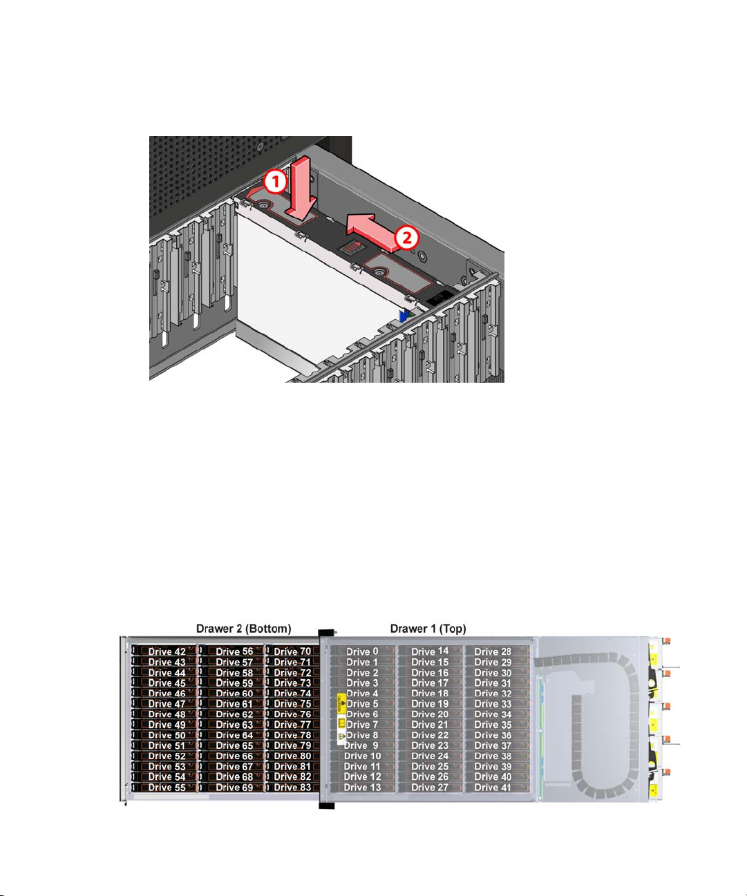
Installing the Media Drives
4. Push the media drive downwards and hold it down while sliding the drive carrier plate in the
direction shown in the following figure. This locks the drive in place.
5. Repeat this procedure to install the remaining media drives in the open drawer as follows,
depending on your ISIS | 2500 Engine configuration:
c
t ISIS | 2500-320 — Using the following illustration, install 41 media drives in each
drawer. Do not use the Drive 0 and Drive 42 slots. For more information on drive slots,
see “ISIS | 2500-320 Media Drive Configuration” on page 25
t ISIS | 2500-160 — Using the following illustration, install 28 media drives in the front
slots of the top drawer (drive slots 0 to 27). Install 14 media drives in the front slots of
the bottom drawer (drive slots 42 to 55). For more information on drive slots, see
2500-160 Media Drive Configuration” on page 26
Do not open both drawers simultaneously.
.
.
“ISIS |
49
Page 50
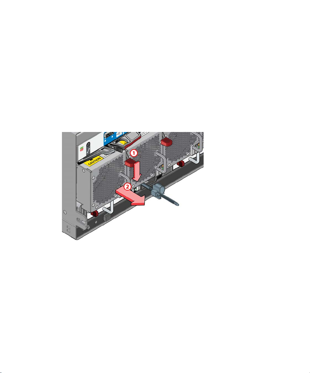
6. After populating one drawer, close it and populate the second drawer (see “Opening and
Closing the Media Drive Drawers” on page 46
Installing the Cooling Modules
This section describes how to install the cooling module.
To insert a cooling module:
1. Position the cooling module so that the red release latch and handle are on the right-hand
side.
2. Slide the cooling module into its slot until the latch clicks in place.
Installing the Cooling Modules
).
3. Repeat this procedure to install the remaining four cooling modules into the cooling module
slots.
Installing the Power Supplies
This section describes how to install the power supplies.
To insert a power supply:
1. Position the power supply so that the red release latch and handle are on the left-hand side.
2. Slide the power supply into its slot until the latch clicks in place.
50
Page 51
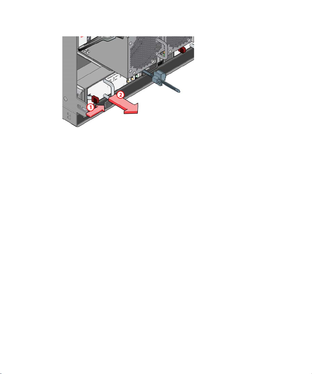
3. Repeat this procedure to install the second power supply into the second power supply slot.
Installing the Engine Controller
This section describes how to install the Engine Controller.
Installing the Engine Controller
The Engine Controller must be in the left slot (when viewed from rear of Engine). The software
n
does not run if Engine Controller is in the right slot.
To insert an Engine Controller:
1. Position the Engine Controller so that the release latch is at the bottom.
2. Open the release latch and rotate it to its most open position.
3. Slide the Engine Controller into its slot until it will go no further.
4. Close the latch until it clicks in place. This will lever the module into its connector on the
midplane. The Engine will automatically detect the new unit.
The Engine Controller shown in the illustration is for reference only, the actual Engine
n
Controller used in the ISIS | 2500 Engine varies from the model shown in the picture.
51
Page 52
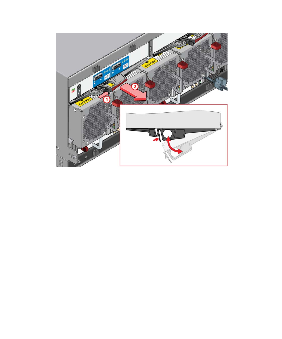
Connecting Power to Equipment
Connecting Power to Equipment
The Avid ISIS | 2500 System Director and Engine each include two power supplies for
redundancy. At least one power supply must be operational for either the System Director or
Engine to function. If a power supply fails, leave it in place until you have a replacement. The
System Director and Engine can each operate on one power supply, but in an unprotected mode.
The ISIS | 2500 Engine cooling modules provides airflow for the Engine. Leave a failed module
in place until a replacement is available to ensure proper airflow is maintained.
The ISIS | 2500 Engine comes with a C19 to C20 power cable. The C19 end is a female
connector which plugs into the power supply on the Engine. The C20 end is a male connector,
used to plug into a Power Distribution Unit (PDU) with C19 style connectors.
For more information about PDUs (in this case, the APC
outputs and a twist lock NEMA LP6-30 input), see:
http://www.apc.com/products/resource/include/techspec_index.cfm?base_sku=AP9570
Avid does not recommend any specific vendor or model of PDU. A PDU is a rack mount ready,
n
high current power strip that can offer a variety of plug types. Purchase a model that suits the
needs of the equipment in your rack.
52
®
Basic Rack PDU with C19 208-240V
Page 53
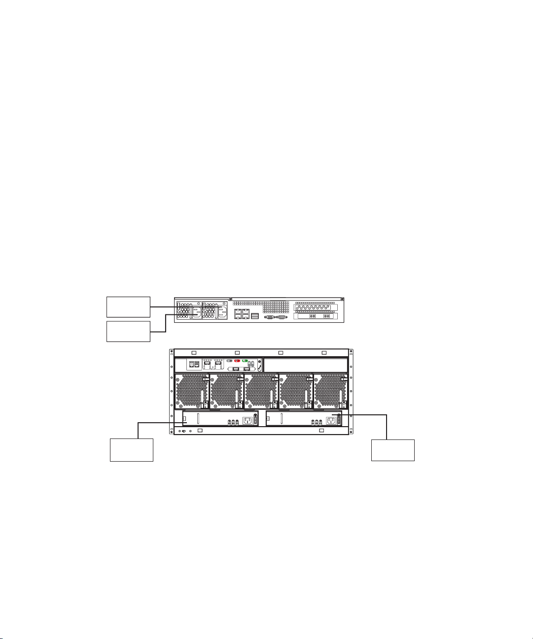
Each ISIS | 2500 Engine power supply draws a maximum of 13 amps of current using 220 Vac.
System Director
220 Volts
30 Amps
Engine
220 Volts
30 Amps
120 Volts
20 Amps
120 Volts
20 Amps
Connect each power supply in the Engine to a different 30-amp circuit. This allows the system to
continue running if one of the two circuits fail.
Each System Director has two power supplies rated at 5.8 amps each. Avid recommends each
power supply be connected to separate 20-amp circuits.
Connecting Power Cords
When using two circuits for the System Director and Engine, configure them as follows:
To connect the power cords to the System Director and Engine:
1. Plug two power cords into the back of the System Director and then plug the other ends into
120v power outlets on separate circuits.
2. Plug two power cords into the back of the Engine and then plug the other ends into 220v
power outlets on separate circuits.
Power Connections
Connecting Power to Equipment
Turning System On and Off
Turn the ISIS system on or off in the following order. Do not turn off the Avid ISIS components
until they have completely turned on.
53
Page 54

Connecting a Keyboard, Monitor, and Mouse
To turn your system on:
1. Turn on the Engine by switching the power switch to the on position on each power supply
module. Allow enough time for the lights on the front panel to turn green.
2. Turn on the System Director.
3. Tell clients to restart their systems and use the Client Manager software to log on and mount
workspaces.
To turn your system off:
1. Exit the Client Manager on all clients.
2. Stop the System Director service using the System Director Control Panel.
3. Turn off the System Director.
4. Turn off the Engine using the switch on the power supply module.
Connecting a Keyboard, Monitor, and Mouse
Use an industry standard USB keyboard, USB mouse and VGA monitor to access the System
Director. You can also use an optional KVM switch if the System Director is installed in a rack
with several servers. Follow the instructions supplied with your KVM switch. You must supply
KVM cables that are compatible with your KVM switch.
n
c
n
There are only two USB ports on the rear of the System Director. When you purchase your KVM,
consider a USB splitter cable so that both your keyboard and mouse can plug into the splitter
cable and use a single USB port on the System Director.
To connect a keyboard, monitor, and mouse to the Avid ISIS:
1. Install your KVM switch in a suitable slot next to the System Director in the rack.
You can also place the monitor on a shelf, and the keyboard and mouse on a sliding tray in
the rack. These items are optional and can be purchased locally or from Avid.
Do not place the monitor on top of the Avid ISIS.
2. Attach the VGA connector on the monitor cable to the 15-pin video port on the back of the
Avid ISIS. Secure the connector with the thumbscrews on the connector. For exact locations
“System Director Rear Panel” on page 17.
see
3. Insert the connector on the keyboard and mouse cables into a USB splitter cable.
If you do not have a USB splitter cable, plug your keyboard and mouse cables directly into the
USB ports on the rear of the System Director.
54
Page 55

Setting Up the Network Address On the Engine
4. Insert the other end of the USB splitter cable into a USB connector on the back of the
System Director.
Setting Up the Network Address On the Engine
The following procedure describes how to configure the Engine.
To configure the engine:
1. Make sure the Engine has been turned on.
Allow about 2 minutes for the Engine to reach a ready status.
2. Turn on the System Director.
3. When prompted for the user name and password, type
password of
The System Director password is preset to is-admin. The System Director Management Console
n
Web Page Administrator user whose default password is blank.
The following static IP addresses have been configured by default on the ISIS | 2500 Engine.
- IP addresses 192.168.0.10
- Subnet mask 255.255.255.0
Make sure no DHCP servers are assigning addresses in the Avid ISIS range.
n
4. Using a System Director (or computer running a Windows operating system), assign a static
IP address of
attach it to the management port of the Engine (left 1 Gb port on Engine Controller).
The following example shows the physical connection between a System Director and
Engine for configuring the IP Address of the Engine Controller.
is-admin
192.168.0.11
.
to the 1 Gb Management Port of the System Director and
administrator
for the user with a
55
Page 56
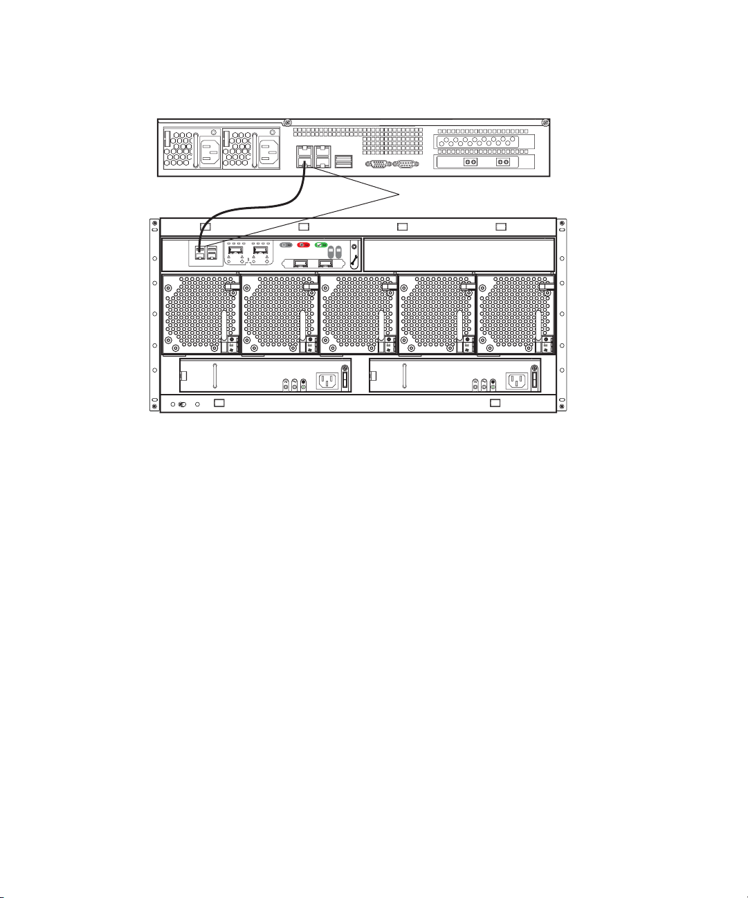
Setting Up the Network Address On the Engine
1 Gb connection
1 Gb managment ports
System Director 1 Gb and Engine 1 Gb Management Ports Connections
5. Open a browser and navigate to the ISIS | 2500 Storage Manager Agent Web page using the
following address:
https://192.168.0.10:5015
.
6. When prompted for the password, type
se-admin
7. Click Network in the left pane of the System tab.
The ISIS | 2500 Storage Manager Agent page appears.
56
.
Page 57
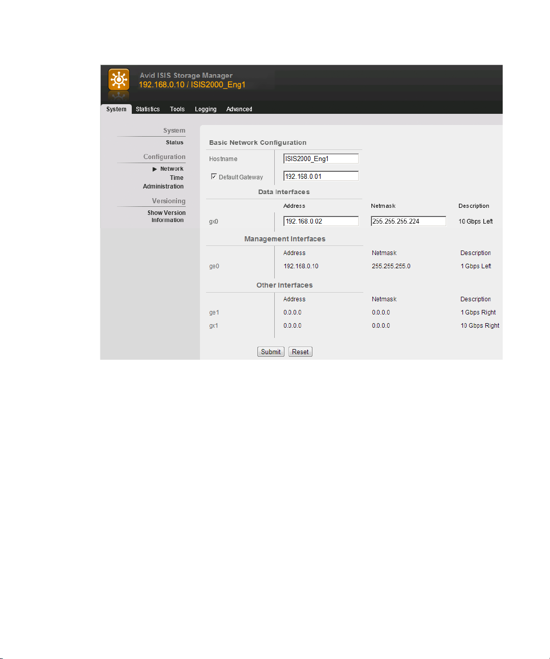
Setting Up the Network Address On the Engine
8. Enter the following into the Basic Network Configuration window:
- The Hostname for the Engine Controller.
- (Option) If using a Gateway, select the Default Gateway check box and enter the
IP addresses of your default gateway.
To use a Zone 3 environment, set the default gateway addresses for the Engine. Get the
addresses from your IS department.
Make sure no DHCP servers are assigning addresses in the Avid ISIS range.
n
- Enter an IP address and netmask address in the Data Interfaces in the gx0 text boxes.
9. Click Submit.
A dialog box might appear with an informational warning to restart the Engine; click the
restart button, enter the “se-admin” password, and the system restarts.
10. Return to the ISIS | 2500 Storage Manager Agent page again and click Time in the left pane
of the System tab and do one of the following.
t If using a network time server, enter the IP addresses of your network time server.
57
Page 58

Connecting Network Cables with a 1 Gb System Director Connection
1 Gb managment port 1 Gb Ethernet
If your network has a network time protocol (NTP) server, you can enter the IP address
of that server in the Chassis Configuration window. Use NTP Server 1 for the primary
NTP server and NTP Server 2 for a secondary NTP server.
t If not using a network time server, manually enter the Date, Time, and Time Zone or
Enable network time protocol.
11. Click Submit.
A dialog box might appear with an informational warning to restart the Engine; click the
restart button, enter the “se-admin” password, and the system restarts. The Engine is now
properly addressed.
12. Assign appropriate static IP address to the network port of the System Director.
13. Attach the System Director to the switch and verify that you can ping the System Director
from another system on the network.
Connecting Network Cables with a 1 Gb System
Director Connection
Connect the ISIS | 2500 System Director with a 1 Gb cable and the Engine with a 10 Gb Ethernet
cable to the switch as described in this section.
Only System Directors with a 10 Gb connection to the switch support CIFS and FTP clients.
n
When using a 1 Gb connection between the ISIS | 2500 System Director and the switch, you must
turn off the CIFS service after you have installed the ISIS | 2500 software. Disable the CIFS
service as described in Turning Off the CIFS Service With a 1 Gb Connected System Director.
The network switch used in the illustrations is the Dell Networking S4810 switch. For a current
n
list of ISIS | 2500 switches, see the Avid ISIS ReadMe.
To cable the system using 1 Gb port:
1. Connect a CAT 5e or CAT 6 Ethernet cable to the lower right-hand 1 Gb port on the rear of
the System Director. No other 1 Gb port on the System Director has been configured for this
connection.
System Director 1 Gb Connection
58
Page 59

Connecting Network Cables with a 1 Gb System Director Connection
1 Gb connection
10 Gb connection
To client 1 Gb connection
Force10 4810 switch with
1 Gb and 10 Gb connections
10 Gb Ethernet LC to LC connection
2. Connect the other end of your network cable to the appropriate port on your ISIS | 2500
switch.
The following example shows the physical connections between a System Director, Engine,
and a Dell Networking S4810 switch.
System Director 1 Gb and Engine 10 Gb Network Connections to Switch
3. Connect a 10 Gb optical network cable to left 10 Gb port (as seen from the rear of the
4. Connect the other end of the 10 Gb network cable to a 10 Gb port on your ISIS | 2500
Engine) on the Engine Controller of the ISIS 2000 Engine. No other 10 Gb port on the
Engine has been configured for this connection.
The 10 Gb port on the ISIS | 2500 Engine Controller requires an SFP+ transceiver. When
using SFP+ transceivers, Short Range (SR) is the preferred choice over Long Range (LR).
switch.
Depending on the type of switch you have, an X2 or SFP+ transceiver might be needed for
the switch port.
59
Page 60

Connecting Network Cables with a 10 Gb System Director Connection
The Dell Networking S4810 switches need SFP+ transceivers with an LC to LC cable
n
connection. The Cisco 4900M switches need an X2 transceiver for the SC type connector with an
LC to SC cable connection.
5. When using a 1 Gb connection between the ISIS | 2500 System Director and the switch, you
must turn off the CIFS service after you have installed the ISIS | 2500 software.
a. The first time you set up the ISIS | 2500 Engine you must connect to the Management
port on the Engine Controller to configure the IP address; see
Address On the Engine” on page 55
b. Install the ISIS | 2500 software as described in Loading the Software.
c. Disable the CIFS service as described in Turning Off the CIFS Service With a 1 Gb
Connected System Director.
.
“Setting Up the Network
Connecting Network Cables with a 10 Gb System
Director Connection
Connect the ISIS | 2500 System Director and Engine to the switch using 10 Gb Ethernet cables
as described in this section.
Depending on the type of switch you have, an X2 or SFP+ transceiver is needed for your 10 Gb
port connections. When using SFP+ transceivers, Short Range (SR) is the preferred choice over
Long Range (LR). The 10 Gb ports on the System Director and the Dell Networking S4810
switches need an SFP+ transceiver for LC type connectors. The Cisco 4900M switches need an
X2 transceiver for SC type connectors. For more information on ISIS cables and transceivers, see
“Supported Cabling” on page 162.
The network switch used in the illustrations in the section is the Dell Networking S4810 switch.
n
For an up-to-date list of ISIS | 2500 switches, see the Avid ISIS ReadMe.
To cable the system:
1. Connect an optical cable to the 10 Gb port on the System Director.
a. Insert an SFP+ transceiver into either 10 Gb Ethernet connector in the Avid
ISIS | 2500 System Director.
b. Connect the optical cable into the SFP+ transceiver you inserted into the 10 Gb port on
the ISIS | 2500 Engine.
60
Page 61

Connecting Network Cables with a 10 Gb System Director Connection
1 Gb managment port 10 Gb Ethernet 1 Gb Ethernet
System Director’s 10 Gb Connection with SFP+ Transceiver
2. Connect the other end of your network cable to the appropriate port on your ISIS | 2500
switch.
Depending on the type of switch you have, an X2 or SFP+ transceiver might be needed for
the switch port.
The Dell Networking S4810 switches need SFP+ transceivers with an LC to LC cable
n
connection. The Cisco 4900M switches need an X2 transceiver for the SC type connector with an
LC to SC cable connection.
The following example shows the physical connections between a System Director, Engine,
and a Dell Networking S4810 switch.
61
Page 62

Connecting Network Cables with a 10 Gb System Director Connection
Force10 4810 switch with
1 Gb and 10 Gb connections
10 Gb Ethernet LC to LC connection
10 Gb Ethernet
LC to LC connections
1 Gb connection
10 Gb connection
Optional 1 Gb Ethernet connection to house network
1 Gb managment port
System Director and Engine 10 Gb Network Connections to Switch
n
3. Connect a 10 Gb optical network cable to left 10 Gb port (as seen from the rear of the
4. Connect the other end of the 10 Gb network cable to a 10 Gb port on your ISIS | 2500
The Dell Networking S4810 switches need SFP+ transceivers with an LC to LC cable
connection. The Cisco 4900M switches need an X2 transceiver for the SC type connector with an
LC to SC cable connection.
5. Repeat steps 3 and 4 if connecting a multiple ISIS | 2500 Engines (up to five ISIS | 2500
Engine) on the Engine Controller of the ISIS 2500 | 2000 Engine. No other 10 Gb port on the
Engine has been configured for this connection.
The 10 Gb port on the ISIS | 2500 Engine Controller requires an SFP+ transceiver.
switch.
Depending on the type of switch you have, an X2 or SFP+ transceiver might be needed for
the switch port.
Engines are supported).
62
Page 63

Connecting Network Cables with a 10 Gb System Director Connection
6. Finish the setup as follows:
a. The first time you set up the ISIS | 2500 Engine you must connect to the Management
port on the Engine Controller to configure the IP address; see “Setting Up the Network
Address On the Engine” on page 55
.
b. Install the ISIS | 2500 software as described in
“Loading the Software” on page 81.
63
Page 64

3 Preupgrade Information
This chapter applies only if you are upgrading an ISIS 2000 from an earlier software version. If
not, see
Gather the following information before the upgrade. This information is critical to
troubleshooting an Avid ISIS.
• Current Avid ISIS software version
• Avid ISIS Administrator password
• Number of Avid ISIS Engines
• Drive size (ISIS 2000 supports 3 TB drives; ISIS | 2500 supports only 4 TB drives)
• Number of Storage Groups
• Number and type of editing clients: (Windows or Macintosh, and using what zones)
• Number of AirSpeeds
• Other workgroup server details (for example Interplay; host names, passwords, and
Zone 2 Switch Information
“Installing Software and Configuring the System” on page 80.
versions)
Note the following switch information:
• Switch manufacturer and model (Cisco/Foundry)
• Number of switches
• Location of configuration files
System Director Information
Note the following System Director information:
Virtual Network Name and IP Addresses
1 Gb port IP address
Page 65

10 Gb port IP address
Virtual ISIS Name
System Director 1
Host name
Administrator Password
IP address
ISIS IP Address
Default Gateway
First failover IP address
Second failover IP address
System Director 2
ISIS Engine Information
Host name
Administrator Password
IP Address
ISIS IP Address
Default Gateway
First failover IP address
Second failover IP address
ISIS Engine Information
Fill out the following Engine IP address information for the on site equipment.
Engine #1, Serial Number
Engine IP:
65
Page 66

Engine #2, Serial Number
Engine IP:
On Site Spares
List all Avid ISIS spare parts that are onsite:
Spare Components and Cables
Part Quantity Firmware Version (if known)
Drives
On Site Spares
XFP, X2, and SFP+
(used with external switches)
®
network boards
Intel
10 Gb fiber cable N/A
CAT5e/6/7 cable N/A
®
Xenpack
3rd party switches
Additional Parts Available
(if Cisco)
Spares Checklist
Use the following list to assure that you have the correct parts onsite when performing any Avid
ISIS upgrade. This can be a mix of customer spares and parts brought onsite by upgrade
technicians.
N/A
•2 — drives
• 1 — SFP+
66
Page 67

Additional spares for a comprehensive spares parts list:
• If Cisco switches are in use: 1 Xenpack, 1 SC-LC cable
• If Dell Networking switches are in use: 1 additional SFP+, 1 LC-LC cable
Spares Checklist
67
Page 68

4 Upgrade Guidelines
This section applies only if you are upgrading an ISIS 2000 from an earlier software version. If
not, see
This section summarizes the tasks to perform when upgrading Avid ISIS 2000. All Avid ISIS
upgrades are to be performed by Avid ISIS Avid Certified Support Representatives (ACSR).
• If you have not already noted the host names, passwords, IP address, and other important
• Do not perform an Avid ISIS system upgrade if your network is not in optimum working
• If you have documented the preupgrade information and your Avid ISIS is healthy, you can
“Installing Software and Configuring the System” on page 80.
network details; see
order; see
start the Avid ISIS system upgrade; see
“Health Check” on page 68.
“Preupgrade Information” on page 64.
“Software Upgrade” on page 69.
• After you finish the upgrade, confirm everything is functioning properly; see
System Verification” on page 76
Health Check
Before changing the system, perform the following quick checks to verify that the system is in
good working order. Do not perform an upgrade if there are any issues with the system. Correct
all problems before performing the upgrade.
Things to check before upgrading:
1. Log into the ISIS Management Console and click Storage Managers. All Storage Managers
have a green icon when functioning normally; investigate any error statuses.
2. Open a command window and ping the System Director. Make sure you can ping the System
Director and that it can access any client on the switch.
3. Ping the default gateway from System Director and make sure it is accessible from any point
in the network. You can ping directly from the Tools > Network Utilities page in the
Management Console.
“Post Upgrade
.
Page 69

Software Upgrade
4. (Dual System Director Configuration) Log into the System Director and open the System
Director’s Control Panel. Make sure both paths are up, and standby is receiving and
replicating metadata. Check the Metadata Status panel in the System Director’s Control
Panel. Make sure the date stamp in the saved and replicated fields is current and updating
frequently. Standby instructions apply only if there is a failover machine present.
5. Check the system event logs on the System Directors for recent error events.
6. Perform a thorough physical inspection of the network cables:
- Find and fix all missing retainers, strains, sharp bends, signs of physical abuse.
- Make sure that labels are visible, physically firmly in place, and legible.
- Confirm that all fans and ventilation areas are free of obstructions, dirt, lint, and debris.
- Make sure that there is clearance front and rear to allow components to be replaced
without obstructions for their full chassis travel length.
- Make sure cables are not zip tied to the power supplies or the switches.
7. (Dual System Director Configuration) Perform System Director Active to Standby Failover
— Turn off one of the System Directors and verify in the System Director Control Panel that
the Active Mode indicator has turned red. Turn the System Director back on and see that
Active Mode displays Standby.
8. Check the system drive status on the System Director.
On the ISIS | 2500 System Director, click Start > Programs > Intel -> Intel Rapid Storage
Technology right-click the Intel Rapid Storage Technology icon in the task bar. The icon is a
green check mark when the drives are healthy.
Software Upgrade
After noting the necessary network and system component information listed in “Preupgrade
Information” on page 64
procedure for upgrading the ISIS | 2500 - 2000 software. Read the Avid ISIS ReadMe for issues
or notes specific to the latest release.
To upgrade ISIS 2000 v4.2 and earlier to v4.5 and later:
1. Download the ISIS software kit from the Avid Download Center
www.avid.com/US/support/downloads) to your System Director.
(
2. If running a System Director failover configuration, stop the Standby System Director using
the ISIS Control Panel to prevent failover during the upgrade.
3. Make a copy of your current metadata files. The following are the file names and where they
are located:
you are ready to upgrade the Avid ISIS. The following is a typical
69
Page 70

Software Upgrade
Metadata location
D:\Program Files\Avid\ISIS System Director
- Partition0
- Partition1
- PartitionDump.bin
4. Load the ISIS software kit on the System Director.
5. Double-click the Autorun.exe file (in Avid ISIS v4.5 and v4.6) or the AvidISISSetup.exe file
(in Avid ISIS v4.7 and later) in the software kit.
The installer detects the existing version of the installed software (if any) and displays the
components that need to be upgraded in the splash screen.
6. If not already selected, select ISIS | 2500 - 2000 System Director from the “Select Software
Package” menu.
7. Click Apply.
8. Follow the screen prompts accepting the defaults and License agreement.
When uninstalling or upgrading the ISIS | 2500 software, you might get prompted to confirm the
n
removal of the File Gateway software. Type Y to confirm the removal and continue with the
upgrade.
9. Once the installation is complete, click Finish.
You are prompted to restart the System Director. After the System Director has restarted,
continue with the next step.
10. Upgrade your Storage Manager using the ISIS Management Console > Storage Managers.
Select the original Storage Manager and click Upgrade.
The Upgrade Storage Managers window opens.
11. Select the .zip file for the new release, and click Upgrade.
If you have an ISIS | 2500-160 configuration your upgrade is finished.
If you have an ISIS | 2500-320 configuration, complete the remaining steps.
12. (ISIS | 2500-320) Select the Storage Manager from the list and click Details.
The Status for the upgrade is shown in the Details pane at the right of the window. Click
Refresh to display the updated Status. When the Status displays “Data Conversion Mode,”
continue with the next step.
13. (ISIS | 2500-320) Double-click the IP address of the original Storage Manager in the Details
pane to open ISIS 2000 Storage Manager Agent Web page.
14. (ISIS | 2500-320) When asked for the password, type
The ISIS | 2500 Storage Manager Agent page appears.
70
se-admin
.
Page 71
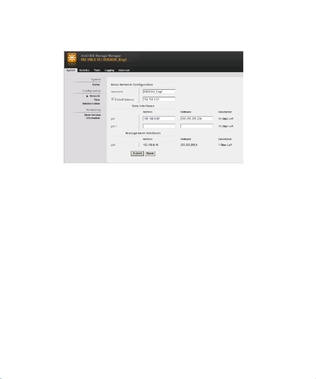
Software Upgrade
15. (ISIS | 2500-320) Click Network in the left pane of the System tab.
16. (ISIS | 2500-320) Enter an IP address in the gx0:1 and Netmask text boxes in the Data
Interfaces section.
n
n
c
Starting with the ISIS v4.5 release, the Engine Controller in the ISIS | 2500 Engine requires
dual IP addresses for ISIS | 2500-320 systems. This new IP address must be in the same
subnet as the original IP address.
A second physical cable is not needed; both IP address are handled through the existing 10 Gb
connection between Engine Controller and the switch.
17. (ISIS | 2500-320) Click Submit.
a. A dialog box appears warning you an Engine reboot is required; click Reboot.
b. A second dialog box appears; type
18. (ISIS | 2500-320) When the Engine has restarted, open the Storage Manager page in the
Management Console.
When you upgrade from v4.2 and earlier to v4.5 and later, two Storage Managers are shown in
the Storage Managers page displaying half the capacity that was previously listed and the Status
column displays “Data Conversion Mode.” This is normal behavior when you upgrade from v4.2
and earlier to v4.5 and later.
Do not add any new ISIS | 2500 Engines to this existing Storage Group until the ISIS v4.5
or later upgrade data conversion redistribution has completed.
19. Update your Avid ISIS client software.
se-admin
. in the password box and click Reboot.
71
Page 72

ISIS | 2500-160 to ISIS | 2500-320 Engine Upgrade
System Director Intel Pro Driver Configuration
The Avid ISIS installer automatically sets the Intel Pro/1000 NIC for correct operation in an ISIS
system. The following settings are provided for reference only.
1 Gb Network Settings On The Engine
Option Setting
Flow Control Disabled
Interrupt Moderation Disabled
Interrupt Throttling Rate Disabled (OFF)
Receive Buffers 1024
Transmit Buffers 1024
ISIS | 2500-160 to ISIS | 2500-320 Engine Upgrade
The ISIS | 2500-160 has 42 media drives with two drives reserved as hot spares. The drives are
configured in the Avid ISIS-160 Engine as four RAID 6 groups (10 drives in each group) with
two hot spares initially created in the bottom drawer. For slot configurations, see
and Slot Locations” on page 24
.
“Drive Array
When you convert your ISIS | 2500-160 Engine to an ISIS | 2500-320, you are adding 40 media
drives to the open slots in the Engine. The 40 new drives are configured into four more RAID
groups (10 drives in each group) for a total of eight RAID groups in the Avid ISIS-320 Engine.
Once you have updated your ISIS | 2500-160 infrastructure to the latest ISIS software, add the 40
new drives (120 TB) to the existing ISIS | 2500-160 Engine and bind the new Storage Manager.
After the new Storage Manager is bound, you can add additional ISIS 2000 Engines and bind
them. Then select all your new Storage Managers and do a single Add redistribution.
The process for updating your ISIS | 2500-160 to ISIS | 2500-320 Engine is as follows:
To update the ISIS | 2500-160 Engine to an ISIS | 2500-320 Engine:
1. Update your existing ISIS | 2500-160 environment (including the Engine) to the latest
release.
a. Download the ISIS software kit from the Avid Download Center
www.avid.com/US/support/downloads) to your System Director.
(
b. (If applicable) Log into Administrator account on the Standby System Director and stop
the Standby System Director using the ISIS Control Panel.
72
Page 73

ISIS | 2500-160 to ISIS | 2500-320 Engine Upgrade
c. Make a copy of your current metadata files. The following are the file names and where
they are located:
Metadata location:
- Partition0
- Partition1
- PartitionDump.bin
d. Load the ISIS software kit on the System Director.
e. Double-click the AvidISISSetup.exe file in the software kit.
The installer detects the existing version of the installed software (if any) and displays
the components that need to be upgraded in the splash screen.
f. If not already selected, select ISIS | 2500 - 2000 System Director from the “Select
Software Package” menu.
g. Click Apply.
h. Follow the screen prompts accepting the defaults and License agreement.
When uninstalling or upgrading the ISIS | 2500 - 2000 software, you might get prompted to
n
confirm the removal of the File Gateway software. Type Y to confirm the removal and continue
with the upgrade.“Installing the Media Drives” on page 48.
i. Once the installation is complete, click Finish.
You are prompted to restart the System Director.
j. After the System Director has restarted, upgrade your Storage Manager, using the ISIS
Management Console > Storage Managers. Select the Storage Manager and click
Upgrade.
D:\Program Files\Avid\ISIS System Director
The Upgrade Storage Managers window opens.
k. Select the .zip file for the new release, and click Upgrade.
The ISIS | 2500-160 upgrade is finished.
2. Access the ISIS Management Console Storage Manager Agent Page > System tab >
Network and note the hostname and IP addresses.
The default Agent Administrator password is “se-admin.”
n
3. Stop the System Director service using the ISIS Control Panel or Launch Pad.
Once the System Director service is stopped, you must access the Agent page using the
Engine IP address.
73
Page 74

ISIS | 2500-160 to ISIS | 2500-320 Engine Upgrade
4. Shut down the Engine Controller using the Storage Manager Agent Web page via the Engine
IP address:
https://IP_address:5015
.
a. Type the Administrator password into the password field.
The ISIS | 2500 Storage Manager Agent page appears.
b. Click the Advanced tab.
c. Select Shutdown from the left pane.
d. Type the Administrator password into the password field and click Shutdown.
e. Allow one minute for the buffers to clear and turn off the power to the Engine (two
power supply switches).
5. Insert your new-unused ISIS drives into the open drive slots in the ISIS 2000 Engine
according to the “ISIS | 2500-320 Media Drive Configuration” on page 25
on installing media drives, see
“Installing the Media Drives” on page 48.
. For instructions
If you have one or more used drives, you must clear the foreign configuration after they are
installed in the Engine, see
“Clearing Foreign Configurations on Used Drives” on page 76.
6. Turn on the ISIS Engine and wait a couple minutes to let the drives come up to speed.
7. Start the System Director service using the ISIS Control Panel or Launch Pad.
8. Open the Storage Manager window, using the ISIS Management Console > Storage
Managers.
9. Select the original Storage Manager from the list and click Details.
10. Double-click the IP address of the original Storage Manager in the Details pane to open
ISIS 2000 Storage Manager Agent Web page.
74
Page 75

ISIS | 2500-160 to ISIS | 2500-320 Engine Upgrade
11. You are asked for the password. Type
The ISIS | 2500 Storage Manager Agent page appears.
12. Click Network in the left pane of the System tab.
13. Enter an IP address in the gx0:1 and Netmask text boxes in the Data Interfaces section.
Starting with the ISIS v4.5 release, the Engine Controller in the ISIS | 2500 Engine requires
dual IP addresses for ISIS | 2500-320 systems. This new IP Address must be in the same
subnet as the original IP address.
se-admin
.
n
c
A second physical cable is not needed, both IP address are handled through the existing 10 Gb
connection between Engine Controller and the switch.
14. Click Submit.
a. A dialog box appears warning you a Engine reboot is required; click the Reboot button.
b. A second dialog box appears, type
15. When the Engine has restarted, open the Storage Managers page in the Management
Console.
Do not add any new ISIS | 2500 Engines to this existing Storage Group until the ISIS v4.5
upgrade data conversion redistribution has completed.
16. Access the Storage Manager Agent Web page for the new Storage Manager.
17. Click RAID Diagnostics > Create RAID Config in the left pane of the Advanced tab.
This creates the RAID groups and could take several minutes, wait until a message informs
you that the configuration has completed.
se-admin
75
. in the password box and click Reboot.
Page 76

18. Bind your new Storage Manager, using the ISIS Management Console > Storage Managers
page. For binding instructions, see “Binding the Storage Managers” on page 88
After the new Storage Manager is Bound, you can add additional ISIS | 2500 Engines and Bind
n
them. Then select all your new Storage Managers and do a single Add redistribution. For Add
redistribution instructions see the Avid ISIS Administration Guide.
19. Update the software on your Avid ISIS clients.
Clearing Foreign Configurations on Used Drives
If installing used drives into your ISIS | 2500 Engine, use the following procedure to clear the
configuration and make the used drive into a raw spare.
To replace a drive with a drive that is not raw:
1. To open the Storage Manager Agent, do one of the following. For more information see the
Avid ISIS Administration Guide.
t From the Storage Managers tool, select an IP address from the IP Addresses panel of the
Details panel, and click the Info button.
t From the System Director desktop, click the “Storage Manager Agent Page” button on
the ISIS Launch Pad.
Post Upgrade System Verification
.
2. Type the Administrator password into the password field.
The default Agent Administrator password is “is-admin.”
n
3. Click the Advanced tab.
If the System Status Panel in the Management Console reports a foreign disk or no spare.
Use this function to clear the foreign configuration and create a spare disk. This function
requires the Administrator password.
c
Resetting a disk is a destructive operation which will permanently delete all data currently
stored on the disk.
4. Select Clear Foreign Config from the left pane.
5. Type the Administrator password into the password field.
Post Upgrade System Verification
After upgrading a system it is important to do a series of checks to verify that all upgraded
components are functioning optimally.
76
Page 77

Post Upgrade System Verification
To verify the upgrade:
1. Verify network connectivity for all components:
a. Ping all Engines.
b. Ping System Director from any client.
c. Ping the virtual System Director.
2. Verify the System Director is functioning properly by checking the following:
a. Check if any new errors are getting generated in the event logs.
b. Lights in System Director’s Control Panel are green (some lights will be blue).
c. Metadata is replicating between the two System Directors. The Standby is toggling
between receiving and replicated. Check the Metadata Status panel on the standby.
Make sure the date stamp in the saved and replicated fields is current and updating
frequently.
d. Check the RAID status on the System Director.
On the System Director, click Start > Programs > Intel -> Intel Rapid Storage
Technology right-click the Intel Rapid Storage Technology icon in the task bar. The icon
is a green check mark when the drives are healthy.
3. Perform System Director Active to Standby Failover — Turn off one of the System
Directors and verify in the System Director Control Panel that the Active Mode indicator has
turned red. Turn the System Director back on and see that Active Mode displays Standby.
4. Run PathDiag on a client. To start the PathDiag Tool:
a. Do one of the following:
- (Windows) Select Start > All Programs > Avid > PathDiag.
- (Macintosh) Select Go > Applications, and then double-click the AvidISIS folder,
and then click the PathDiag.app file.
77
Page 78

Post Upgrade System Verification
b. Click Setup.
c. Set “Path to Test” to a mounted ISIS workspace letter. (Check in my computer if not
sure) Make sure its an ISIS workspace and not the internal C: drive.
d. Set the duration 10 minutes.
e. Click Custom Test and set the following parameters:
Custom Test
Settings
File Access Method Automatically select Automatically select
Reads vs Writes Writes, then Reads (Sequential) Writes, then Reads (Sequential)
Transfer Size 4096 16384
Transfer Rate Unlimited Unlimited
Max File Size 1000 1000
1 Gb client
(not bandwidth limited)
10 Gb Client
(not bandwidth limited)
f. Click Ok and Start.
- 1 Gb clients that are not bandwidth limited can expect at least 65 MB/sec in the Path
Diag tool.
78
Page 79

Post Upgrade System Verification
- 10 Gb clients that are not bandwidth limited can expect at least 500 MB/sec for
reads and at least 200 MB/sec for writes in the Path Diag tool.
5. While Path Diag is running check the system to make sure that there are no Network
Degraded status indications. Check the following:
a. In the ISIS Management Console, click Storage Managers. All drives are green and not
displaying any Network Degraded states.
b. Check the drives by browsing to the Storage Manager web page and verify you have a
green indicator. Click Refresh in the Management Console page to update the page.
6. Check your ISIS | 2500 clients in Zone 2 and 3 using Path Diag.
a. Run a Path Diag client over each switch.
b. Run a couple of Zone 3 path diag clients and verify consistent performance.
ISIS | 2500 does not support Zone 1 clients. A Zone 3 client might not have the bandwidth of a
n
Zone 2 client.
79
Page 80

5 Installing Software and Configuring the
System
This chapter describes how to install the Avid ISIS software on a new system and configure the
System Director and other Avid ISIS hardware.
If you have questions, call your Avid representative or your local ACSR.
c
Before you start the procedures in this chapter, familiarize yourself with the information in
“Avid ISIS | 2500 System Overview” on page 14, and the Avid Network and Switch Guide.
Software Installation
Make sure the System Director and Engine are cabled and attached to an ISIS network switch;
“Connecting Network Cables with a 10 Gb System Director Connection” on page 60.
see
If you are upgrading an existing ISIS 2000 to the latest version of ISIS software, see
Guidelines” on page 68
Configuration Overview
The following list summarizes the System Director and Engine setup.
1. Assign an IP addresses to your Engine; see
Engine” on page 55
The ghost image on the System Directors does not set the IP addresses of the onboard network
n
ports or the dual 10 Gb network ports on the PCI bus; the system is set for DHCP.
2. Load the System Director software. This software is used to create a file system on the
System Director, bind the drives to the software on the System Director, create Storage
Groups, and administer the Avid ISIS system. See
.
.
“Upgrade
“Setting Up the Network Address On the
“Loading the Software” on page 81.
3. Perform administrative functions: bind Engines, create Storage Groups, and do other
administrative functions. See
page 83
4. Load the client software; see the Avid ISIS Client Guide.
.
“Creating an Active File System on the System Director” on
Page 81

Loading the Software
The System Director software is loaded onto the System Director using a USB flash drive. The
system ships with two USB flash drives:
• One USB flash drive is blank, for you to download the application software.
Any USB flash drive is supported for loading the software kit as long as it has at least 2 GB of
n
storage.
• The second USB flash drive contains the Avid ISIS Product Recovery image.
To load the Avid ISIS software:
Software Installation
1. Log in to the System Director as Administrator (default password:
The Avid ISIS | 2500 product documentation is in PDF format. You can access the
n
documentation in the AvidISISDocumentation folder on the Avid ISIS installer kit. Download and
install Acrobat Reader on your Avid ISIS | 2500 before you can access the PDF documentation.
2. Make a folder for the software kit on your root directory (C:\) of your System Director.
3. Insert the USB flash drive with software kit into any of USB ports on your System Director.
You can run the software installer from the USB flash drive. Copying the software kit to the Avid
n
ISIS makes the kit accessible if you need it in the future.
a. Double-click the computer icon on the desktop.
b. Double-click the USB flash drive icon in the window and copy the software kit into the
new folder you created on the Avid ISIS | 2500 system.
4. (Option) The Avid ISIS | 2500 software kit is also available on the Avid Download Center
www.avid.com/support/downloadcenter). Uncompress (unzip) the downloaded software kit
(
in the new folder on the Avid ISIS | 2500 system.
5. Double-click the AvidISISSetup.exe file in the software kit.
The installer splash screen appears.
is-admin
).
81
Page 82
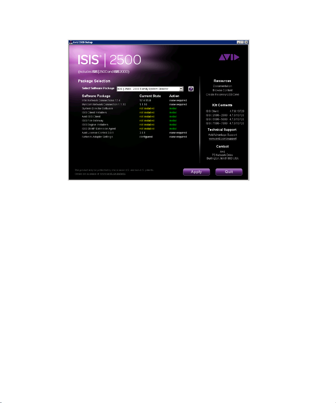
Software Installation
Avid highly recommends that you click the Documentation link. This displays the ReadMe file
n
that provides the latest information regarding the Avid ISIS | 2500 system. You must have Adobe
Reader installed to view the PDF.
6. Select ISIS | 2500 - 2000 Family System Director from the “Select Software Package”
menu.
When setting up the ISIS | 2500 Engine for the first time, the RAID set configuration is
performed when you Upgrade the Storage Managers in the Management Console. This
function is not performed if your RAID set has already been configured; for example, when
upgrading the software version.
When you initially install the Avid ISIS | 2500 system and initialize the RAID set, it will take
n
approximately 72 hours regardless if you have an ISIS | 2500-320 TB or ISIS | 2500-160 TB
Engine configuration. During initialization, the system is functional and able to support a
limited amount of client traffic. Client traffic can significantly increase the initialization time.
For more information about the initialization time, see the Avid ISIS Performance Guides.
7. Click Apply.
8. Follow the screen prompts accepting the defaults and License agreement.
When uninstalling or upgrading the ISIS | 2500 software, you might be prompted to confirm the
n
removal of the File Gateway software. Type Y to confirm the removal.
82
Page 83

9. Once the installation is complete, click Finish. The installer prompts you to restart the
System Director for the update to take effect.
Separate VLAN on Switch for ISIS | 2500
ISIS | 2500 systems typically are integrated with ISIS | 7500 or ISIS | 5500 environments. Each
ISIS system must be in a different broadcast domain or VLAN. The ISIS | 2500 System Director
and ISIS | 2500 Engine are connected to ISIS | 7500 or ISIS | 5500 switches that have been
configured with a separate VLAN for the ISIS | 2500 components. See your site network
administrator for assistance with configuring the separate VLAN on your switch.
Activating the License Key
You must activate your Avid ISIS software before you can make an Active File System. After
installing your software, see
Previous versions of Avid ISIS software use an application key plugged into the System Director
n
to allow clients to connected to the ISIS infrastructure. New ISIS systems ship with software
licensing that is activated online. Software licensing is only required with new ISIS installations.
Clients cannot access the Avid ISIS software until the license key has been activated.
“Avid ISIS Software Licensing” on page 102.
Software Installation
If configuring a Dual System Director for metadata redundancy, you will need a second
application key with the second System Director. For more information, see
System Director Failover” on page 92
.
Creating an Active File System on the System Director
After the software installation and the System Director has restarted, new installations must be
initialized by creating an Active File System on the System Director.
“Configuring
83
Page 84
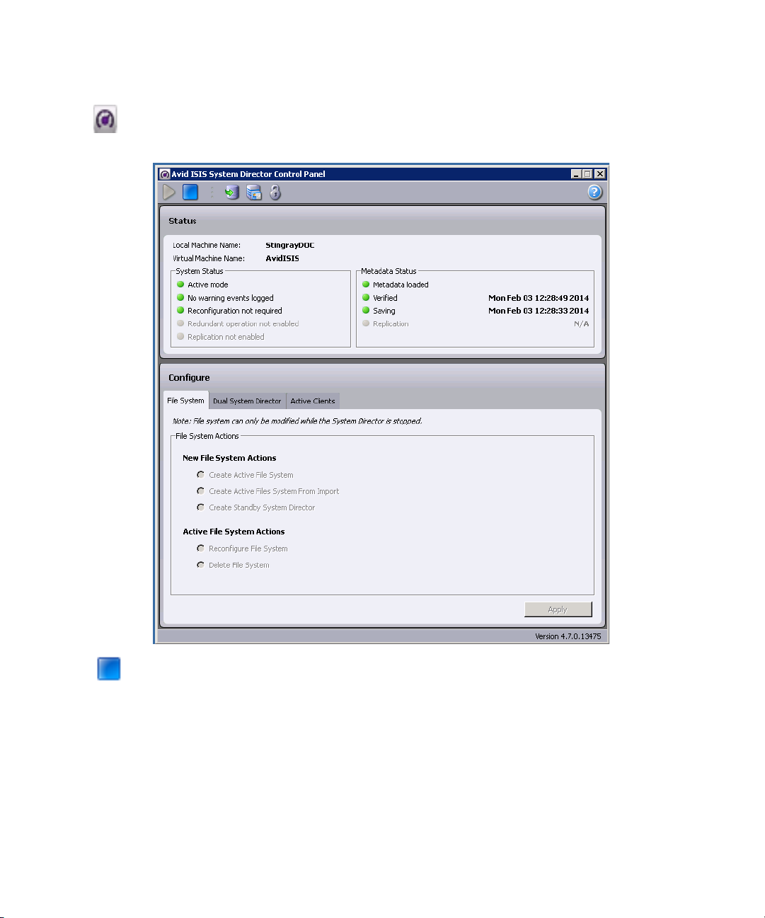
Software Installation
To create an Active File System:
1. In the ISIS Launch Pad, click ISIS Control Panel icon or Start > Programs > Avid > ISIS
System Director and select Control Panel.
c
2. Click Stop System Director.
The Configure File System tab becomes active.
3. Click Configure File System.
When you click Create Active File System, you lose all existing media assets on the system.
This is a non-recoverable action. Use this command with extreme caution.
4. (First System Director) Select Create Active File System and click OK.
The Avid ISIS System Director service automatically starts when complete. In the System
Director Control Panel, the “System Director is running” display turns green.
84
Page 85
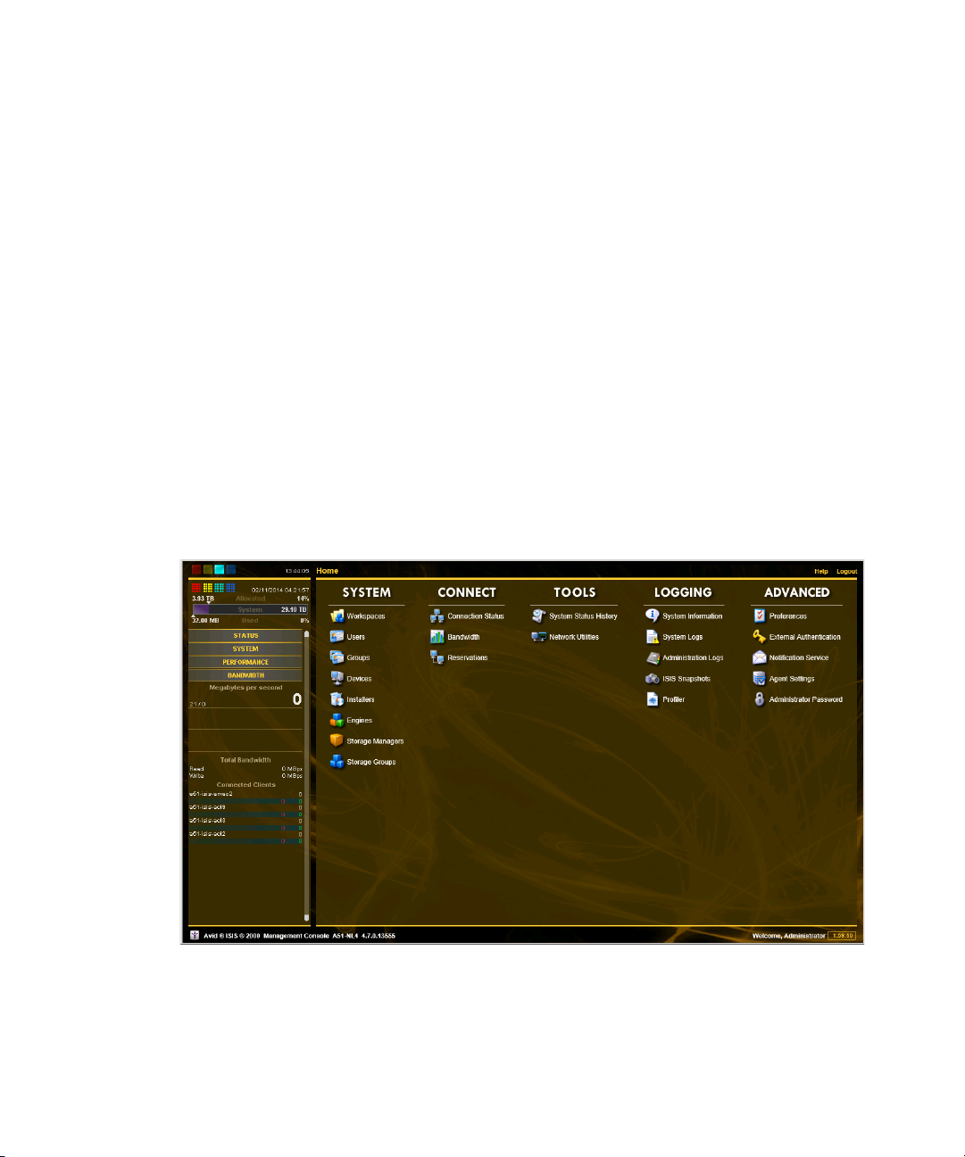
5. (Option) If creating a Standby System Director in an metadata redundancy configuration,
see “Configuring System Director Failover” on page 92
Installing Software on the Engine
After you have loaded new software on the System Director, upgrade the software on the Engine.
You can use Management Console from anywhere to perform the following functions, but you
usually do it from the System Director:
• Upgrade the Storage Manager with the proper/latest software
• Create Workspaces
To load the Engine software:
1. Go to http://IP address of System Director (or virtual name).
2. Log into the System Director.
The default Administrator password is blank.
n
The ISIS Management Console opens.
Software Installation
.
3. Click Storage Managers.
4. Select the Storage Manager in the list.
85
Page 86
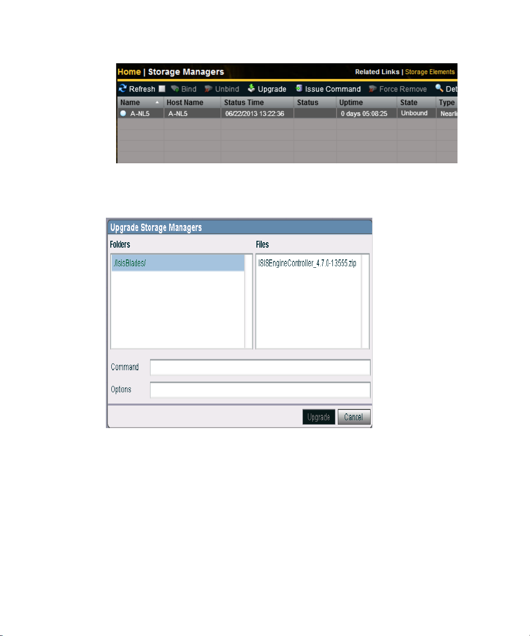
5. Click Upgrade.
The Upgrade Storage Managers window opens.
Software Installation
6. Select the .zip file, and click Upgrade.
The Storage Manager installation takes approximately 10 minutes. The progress of the
upgrade is shown in the Status column in the Storage Managers view. When the upgrade is
complete, the Status column is empty.
Once the Storage Manager upgrade has completed, the software automatically starts building
n
the RAID sets in the ISIS | 2500 Engines. Due to the size and number of drives in the Engine, the
RAID configuration takes a couple of days to complete. Clients can use the ISIS | 2500 system
during this time; however, the more client activity on the Engine, the longer it takes to finish the
RAID configuration.
86
Page 87
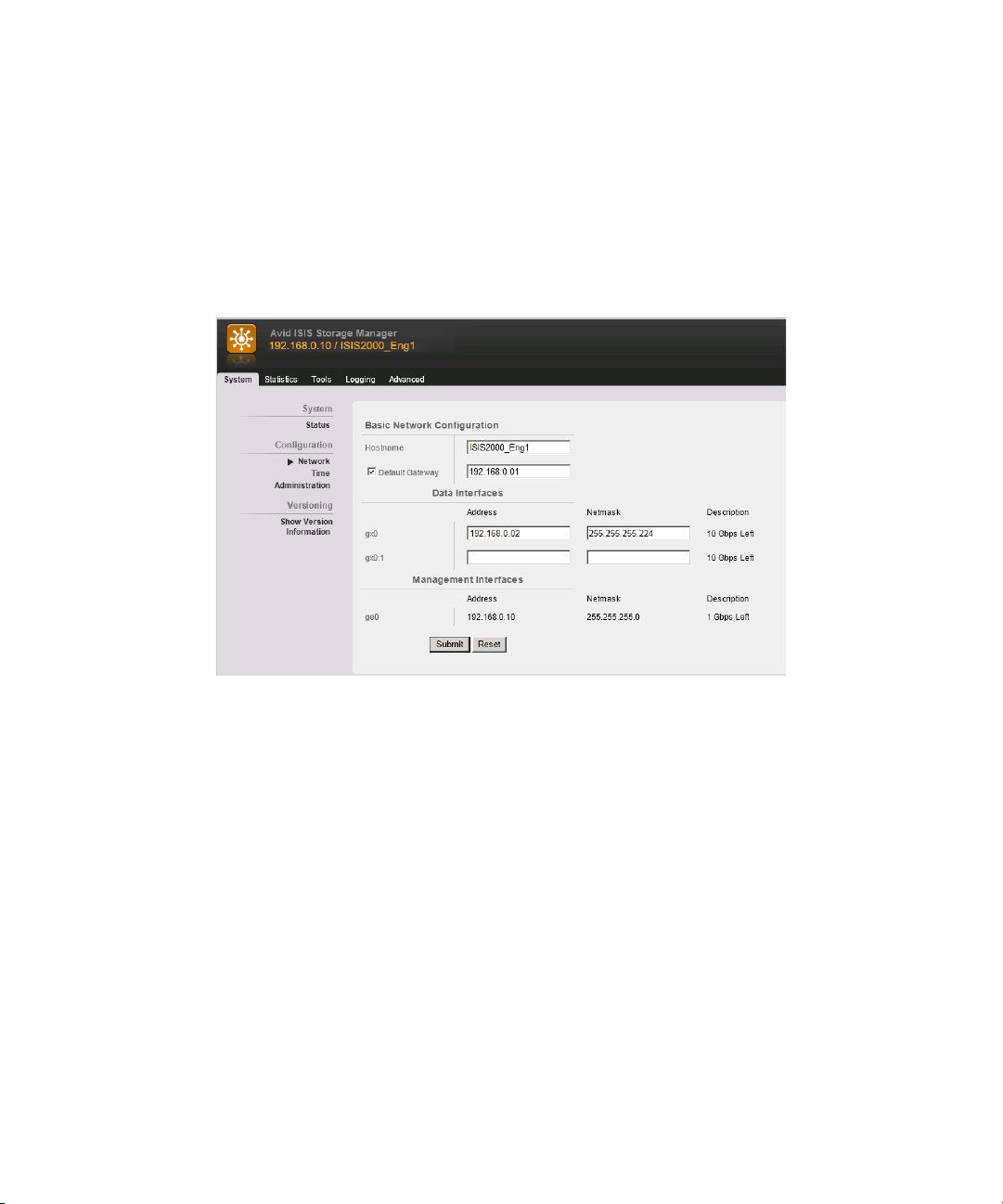
Software Installation
7. On an ISIS | 2500-320 only, do the following additional steps:
a. Double-click the IP address of the original Storage Manager in the Details pane to open
ISIS 2000 Storage Manager Agent Web page.
b. When prompted for a password, type se-admin
c. Click Network in the left pane of the System tab.
The ISIS Storage Manager Agent page appears.
d. Enter an IP address in the gx0:1 and Netmask text boxes in the Data Interfaces section.
The ISIS v4.5 release provides dual IP addresses for the Engine Controller in the
ISIS | 2500 Engine. This new IP Address must be in the same subnet as the original IP
address.
A second physical cable is not needed, both IP address are handled through the existing 10 Gb
n
connection between Engine Controller and the switch.
e. Click Submit.
f. A dialog box appears warning you an Engine reboot is required; click Reboot.
g. A second dialog box appears; type
h. When the Engine has restarted, open the Storage Manager page in the Management
Console.
You will notice there are now two Storage Managers in the Storage Managers page.
n
se-admin
87
. in the password box and click Reboot.
Page 88
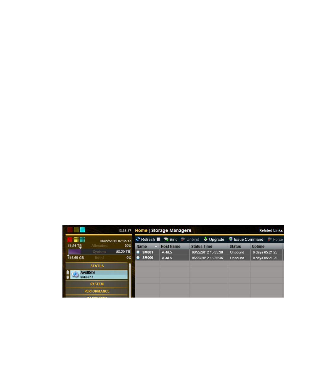
Binding the Storage Managers
After you have created an Active File System, bind the Storage Managers using the Management
Console. If you have more than one Engine in your ISIS | 2500 configuration, they appear listed
in the Storage Manager page. One or multiple Storage Managers can be bound.
This procedure assumes you are creating an Active File System on a new unused Engine. If you
n
attempt to create a File System on an Engine that has been used before, your Storage Managers
might enter an Orphaned state. To remove an Orphaned state, search the Avid ISIS
Administration Guide for instructions on “Removing Orphaned Storage Managers.”
To bind the Storage Managers:
1. Type http://IP address of System Director in your browser.
If already logged into the System Director, click the Management Console icon in the
Launch Pad.
2. Log into the System Director and access the Management Console.
The default Management Console Administrator password is blank (no password).
n
3. Click the Storage Managers icon or click the unbound Status message in the System Status
console.
Software Installation
If you have an ISIS | 2500-160 configuration, one Storage Manager is displayed. Two Storage
n
Managers are displayed for each ISIS 2500-320 Engine.
4. Select the Storage Managers listed in the Storage Managers page.
Multiple Storage Managers can be selected and bound.
5. Click Bind.
6. Click Yes to confirm the request.
7. Click Refresh to see the status circle next to the Name change to green when complete.
88
Page 89

Creating a Storage Group
A Storage Group requires at least one Storage Manager. The ISIS | 2500-160 Engine can be
configured for one Storage Group, and the ISIS | 2500-320 Engine can be configured for one or
two Storage Groups. If you have multiple Engines, all the Storage Managers can be configured
as single Storage Group.
To create a Storage Group, click the Storage Group icon in the Management Console. See the
Avid ISIS Administration Guide for additional information.
Creating Workspaces
Workspaces are locations within a Storage Group to store and segregate data. They appear as
network drives to the clients. You can allow users to access some or all of the workspaces, and
assign permissions for how each user can access the data in a workspace.
To create Workspaces, click Workspaces icon in the Management Console. See the Avid ISIS
Administration Guide for more information.
Creating User Accounts
Software Installation
User accounts allow individual users, or groups of users, access to the workspaces. These
accounts allow users to mount or map Avid ISIS workspaces on their workstations.
To add users, click the User icon in the Management Console. See the Avid ISIS Administration
Guide for more information.
Turning Off the CIFS Service With a 1 Gb Connected System Director
If you are using a 1 Gb connection between the ISIS | 2500 System Director and the switch, you
must turn off the CIFS service. By default ISIS software starts the CIFS service using the 10 Gb
port.
For information on configuring CIFS with a 10 Gb System Director, see the File Gateway Setup
and User’s Guide.
c
Only System Directors with a 10 Gb connection to the switch support CIFS clients. If you
reconfigure your System Director to use a 10 Gb connection between the System Director
and the switch, you must reset this service to run automatically.
If you upgrade or reload the ISIS software, this default CIFS setting is reset to automatically
n
start. You must disable the setting each time the software is installed on the ISIS System Director.
89
Page 90

To start and stop your CIFS service:
1. Right-click My Computer icon and select Manage.
The Server Manager window opens.
2. Expand the Configuration menu in the left pane and select Services.
3. Right-click AvidISISFileGateway in the right pane and select Properties.
Software Installation
4. Select Disabled from the “Startup type” menu.
90
Page 91

5. Click Apply, and then click OK.
6. Close the Server Manager window.
Checking the Status of the System Director
After you have installed the System Director software, an Avid ISIS Launch Pad is displayed on
the System Director Desktop.
To open and close the Launch Pad:
1. If the ISIS Launch Pad is not displayed on the Avid ISIS System Director Desktop, click the
ISIS Launch Pad icon in the Taskbar’s System Tray to display or hide the Launch Pad.
You can also open other ISIS tools by clicking the icons in the Launch Pad.
n
The ISIS Launch Pad is displayed.
Software Installation
2. Start or stop the System Director by clicking one of the following icons in the ISIS Launch
Pad.
t Click the blue square icon to stop the System Director.
t Click the blue triangle icon to start the System Director.
91
Page 92

6 Configuring System Director Failover
This chapter explains how to enable the software for a failover using two System Directors.
The Active and the Standby System Directors must be using the same image on the server; you
n
cannot mix images.
System Director Failover
When using two System Directors, one is referred to as Active System Director and the other one
is the Standby System Director. The File System on the Standby System Director is
synchronized with the Active System Director. If the Active System Director fails, a failover
function switches to the Standby System Director. There might be a brief interruption in client
connectivity but all clients reconnect automatically when the Standby System Director becomes
active. In an attempt to keep the procedure easy to use, we use the following nomenclature:
• When adding a new System Director to an existing Avid ISIS system or creating a failover
system configuration, the original System Director is called the existing System Director and
the new System Director is called new.
• When installing two new System Directors to create a failover system configuration, one
System Director is called Active and the other Standby.
The System Director crossover cables must be connected to the 1 Gb on-board 82567LM-4 and
82574L ports. These two 1 Gb ports are the left two 1 Gb System Director ports (when facing the
rear). The 1 Gb Intel Pro 1000 ports on the right side are not used when configuring dual
ISIS 2000 System Directors. Connect the two System Directors under the following conditions:
• After you have physically configured the system and loaded the Avid ISIS software on both
System Directors.
• When the System Director service is stopped on both systems.
Page 93

Cabling Dual System Directors
Force10 4810 switch
10 Gb Ethernet uses
LC to LC connections
System Directors
Optional 1 Gb house network connection
1 Gb connection
10 Gb connection
Engines
To connect dual System Directors:
1. Connect the two System Directors using a 1 Gb cable (straight or crossover) as shown in the
following figure.
Connect the two bottom-left ports of the System Directors with one Ethernet cable and
connect the two top-left ports of the System Directors with a second Ethernet cable.
System Director Failover
n
2. Enable the software on both systems; see
The configuration information for the notification service (SMTP information, contacts, and
filters) is stored in the registry on the System Director. This information is not currently
“Configure a Failover Connection” on page 94.
replicated to the failover System Director and must be entered manually on both System
Directors. For information on setting up the notification service, see Setting up Error
Notification in the Avi d ISIS Adm i nistration Guide.
93
Page 94

Setting IP Addresses for Crossover Link
Setting IP Addresses for Crossover Link
Avid recommends the System Director IP addresses for failover configurations that are listed
below. If you use different addresses, be sure to note them and have them available before
proceeding. You set the IP addresses in the Network Connections dialog box, which you access
from the Windows Control Panel. For information on setting Windows IP addresses, see the
documentation that came with your operating system.
To set IP addresses:
1. Go to Start > Control Panel > Network Connections for each System Director.
2. Set the Existing System Director to the following TCP/IP addresses for ports 1 and 2:
- Onboard Ethernet port 1 (ETH1) - 192.168.1.1 netmask 255.255.255.0
- Onboard Ethernet port 2 (ETH2) - 192.168.2.1 netmask 255.255.255.0
3. Set the New System Director to the following TCP/IP addresses for ports 1 and 2:
- Onboard Ethernet port 1 (ETH1) - 192.168.1.2 netmask 255.255.255.0
- Onboard Ethernet port 2 (ETH2) - 192.168.2.2 netmask 255.255.255.0
Configure a Failover Connection
Setting up the ISIS system for a System Director failover is done on two System Directors. The
first System Director is referred to as the Active System Director and the second System Director
is referred to as the Standby System Director.
Notify all clients that you are stopping the System Director.
n
To set up a failover connection on the Active System Director:
1. Load the ISIS software on the Active System Director as described in “Loading the
Software” on page 81
2. In the ISIS Launch Pad, click ISIS Control Panel icon or Start > Programs > Avid > ISIS
System Director and select Control Panel.
.
94
Page 95

Configure a Failover Connection
n
c
3. Click Stop System Director.
4. Click Change Virtual System Director Name and type a name in the Virtual System Director
Name text box, then click OK.
You must assign the same virtual name to both System Directors.
5. (First new System Director) Select Create Active File System and click OK.
If you already have a running System Director do not create a new file system. If you create
a new file system on a System Director that already has a file system all of your existing
data will be lost.
The Avid ISIS System Director service automatically starts when complete. In the System
Director Control Panel, the “System Director is running” display turns green.
6. Click Stop System Director.
95
Page 96

Configure a Failover Connection
7. Click the Dual System Director tab.
8. Select “Enable Dual System Director Configuration.”
9. Configure the Virtual Addresses on both systems by doing the following:
a. Choose two unused static IP address that are used as the Virtual IP addresses for both
System Directors. This example uses 192.168.10.253 and 192.168.20.253.
b. Map the Virtual IP address to the corresponding real IP address for each of the System
Directors. This example uses 192.168.10.100 and 192.168.20.100.
c. Register both of the Virtual IPs in DNS with the Virtual System Director Name.
10. In the Local Machine area, do the following:
a. Leave the Monitor port set to 5000. If you have another application that uses port 5000,
change the Monitor port to an available port number. This port number must be the same
on both the existing and the new System Directors.
b. Set the Local Machine First Path IP address to local IP 1: 192.168.1.1.
c. Set the Local Machine Second Path IP address to local IP 2: 192.168.2.1.
d. Set the Remote Machine First Path IP address to: 192.168.1.2.
e. Set the Remote Machine Second Path IP address to: 192.168.2.2.
The Active System Director has now been configured. Leave the Active System
Director as is; stopped and with the ISIS Control Panel and Dual System Director
Configuration window open.
11. Load the ISIS software on the Standby System Director as described in “Loading the
Software” on page 81
12. Click System Director Control Panel from the ISIS Launch Pad or Start > Programs > Avid
> ISIS System Director and select Control Panel.
13. Click Stop System Director.
14. Click Change Virtual System Director Name and type a name in the Virtual System Director
Name text box, then click OK.
You must assign the same virtual name to both System Directors.
n
15. Click the Dual System Director tab.
.
96
Page 97
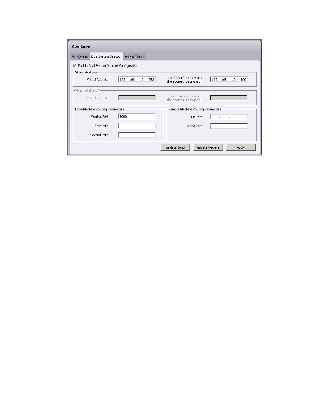
Configure a Failover Connection
16. Select “Enable Dual System Director Configuration.”
17. Configure the Virtual Addresses on both systems by doing the following:
a. Choose two unused static IP address that are used as the Virtual IP addresses for both
System Directors. This example uses 192.168.10.253 and 192.168.20.253.
b. Map the Virtual IP address to the corresponding real IP address for each of the System
Directors. This example uses 192.168.10.101 and 192.168.20.101.
c. Register both of the Virtual IPs in DNS with the Virtual System Director Name.
18. In the Local Machine area, do the following:
a. Leave the Monitor port set to 5000. If you have another application that uses port 5000,
change the Monitor port to an available port number. This port number must be the same
on both the existing and the new System Directors.
b. Set the Local Machine First Path IP address to local IP 1: 192.168.1.1.
c. Set the Local Machine Second Path IP address to local IP 2: 192.168.2.1.
d. Set the Remote Machine First Path IP address to: 192.168.1.2.
e. Set the Remote Machine Second Path IP address to: 192.168.2.2.
The Active System Director has now been configured. Leave the Active System
Director as is; stopped and with the ISIS Control Panel and Dual System Director
Configuration window open.
19. Validate the crossover connections as follows:
a. On the standby (receiving) System Director, click Validate Receive.
b. On the active (sending) System Director, click Validate Send.
97
Page 98
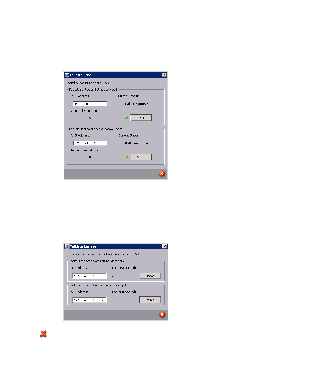
Configure a Failover Connection
Make sure to click Validate Receive on the standby System Director before you click Validate
n
Send on the active System Director. Clicking Send first can result in errors.
20. On the active (sending) System Director, the Validate Send dialog box opens.
At first, the dialog box indicates that it is setting up the communication between the two
System Directors and waiting for a response. When communication is established, the dialog
box message alternates between Sending out inquiry and Valid response. The number of
Successful Round Trips indicates the number of packets sent between the System Directors.
On the receiving System Director, the Validate Receive dialog box displays the packets
received, incrementing for as long as you run the validation test.
21. On each system, close the Validate Send or Validate Receive dialog box.
22. Validate the crossover connections in the other direction.
98
Page 99
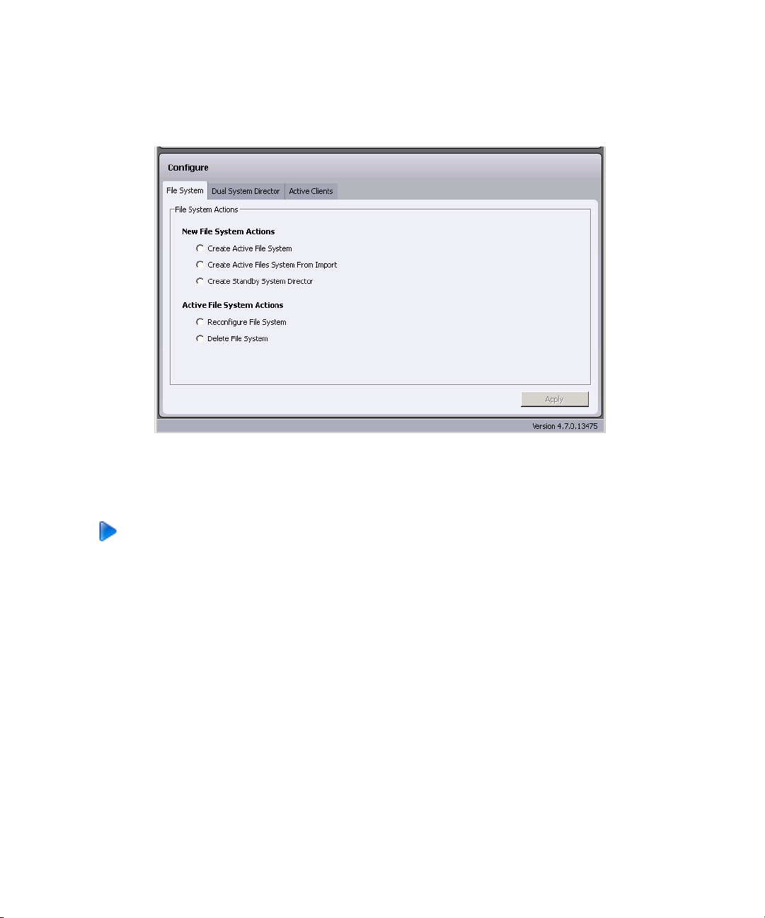
Stopping and Restarting the System Directors
Make sure that the sending and receiving systems show similar results.
23. Click the File System tab on the Standby System Director.
24. Select Create Standby System Director and click Apply.
The Avid ISIS System Director service automatically starts when complete. In the System
Director Control Panel, the “System Director is running” display turns green.
25. Click Start System Director on both the Active and Standby System Directors and close the
ISIS Control Panels on each system.
Stopping and Restarting the System Directors
In an ISIS | 2500 failover configuration, you can stop the Active System Director and watch the
Standby System Director become the Active System Director. When you restart the System
Director that was previously Active, that System Director now becomes the Standby System
Director. If you stop and restart the Standby System Director it remains the Standby System
Director. The following procedures describes how you to stop and start the System Directors.
If you have a failed System Director, stop and restart that System Director. Very often a single
n
stop and start of the System Director corrects the problem.
99
Page 100

Stopping and Restarting the System Directors
To stop and start the System Director using the Launch Pad:
1. If the ISIS Launch Pad is not displayed on the Avid ISIS System Director Desktop, click the
ISIS Launch Pad icon in the Taskbar’s System Tray to display or hide the Launch Pad.
You can also open other ISIS tools by clicking the icons in the Launch Pad.
n
The ISIS Launch Pad is displayed.
2. Start or stop the System Director by clicking one of the following icons in the ISIS Launch
Pad.
t Click the blue square icon to stop the System Director.
t Click the blue triangle icon to start the System Director.
100
 Loading...