

Page 1

Avid® Interplay®Engine
Failover Guide
make manage move | media
™
Avid
®
Page 2

Legal Notices
Product specifications are subject to change without notice and do not represent a commitment on the part of Avid Technology,
Inc.
This product is subject to the terms and conditions of a software license agreement provided with the software. The product
may only be used in accordance with the license agreement.
Avid products or portions thereof are protected by one or more of the following United States Patents: 4,970,663; 5,267,351;
5,309,528; 5,355,450; 5,396,594; 5,440,348; 5,467,288; 5,513,375; 5,528,310; 5,557,423; 5,577,190; 5,584,006; 5,640,601;
5,644,364; 5,654,737; 5,715,018; 5,719,570; 5,724,605; 5,726,717; 5,729,673; 5,745,637; 5,752,029; 5,754,851; 5,799,150;
5,812,216; 5,828,678; 5,842,014; 5,852,435; 5,999,406; 6,038,573; 6,061,758; 6,141,007; 6,211,869; 6,532,043; 6,546,190;
6,596,031; 6,636,869; 6,747,705; 6,763,523; 6,766,357; 6,813,622; 6,847,373; 7,081,900; RE40,107; 7,403,561; 7,433,519;
D352,278; D372,478; D373,778; D392,267; D392,268; D392,269; D395,291; D396,853; D398,912.
Other patents are pending.
This document is protected under copyright law. An authorized licensee of [product name] may reproduce this publication for
the licensee’s own use in learning how to use the software. This document may not be reproduced or distributed, in whole or in
part, for commercial purposes, such as selling copies of this document or providing support or educational services to others.
This document is supplied as a guide for [product name]. Reasonable care has been taken in preparing the information it
contains. However, this document may contain omissions, technical inaccuracies, or typographical errors. Avid Technology,
Inc. does not accept responsibility of any kind for customers’ losses due to the use of this document. Product specifications
are subject to change without notice.
Copyright © 2009 Avid Technology, Inc. and its licensors. All rights reserved.
The following disclaimer is required by Sam Leffler and Silicon Graphics, Inc. for the use of their TIFF library:
Copyright © 1988–1997 Sam Leffler
Copyright © 1991–1997 Silicon Graphics, Inc.
Permission to use, copy, modify, distribute, and sell this software [i.e., the TIFF library] and its documentation for any purpose
is hereby granted without fee, provided that (i) the above copyright notices and this permission notice appear in all copies of
the software and related documentation, and (ii) the names of Sam Leffler and Silicon Graphics may not be used in any
advertising or publicity relating to the software without the specific, prior written permission of Sam Leffler and Silicon
Graphics.
THE SOFTWARE IS PROVIDED “AS-IS” AND WITHOUT WARRANTY OF ANY KIND, EXPRESS, IMPLIED OR
OTHERWISE, INCLUDING WITHOUT LIMITATION, ANY WARRANTY OF MERCHANTABILITY OR FITNESS FOR A
PARTICULAR PURPOSE.
IN NO EVENT SHALL SAM LEFFLER OR SILICON GRAPHICS BE LIABLE FOR ANY SPECIAL, INCIDENTAL, INDIRECT
OR CONSEQUENTIAL DAMAGES OF ANY KIND, OR ANY DAMAGES WHATSOEVER RESULTING FROM LOSS OF USE,
DATA OR PROFITS, WHETHER OR NOT ADVISED OF THE POSSIBILITY OF DAMAGE, AND ON ANY THEORY OF
LIABILITY, ARISING OUT OF OR IN CONNECTION WITH THE USE OR PERFORMANCE OF THIS SOFTWARE.
The following disclaimer is required by the Independent JPEG Group:
This software is based in part on the work of the Independent JPEG Group.
This Software may contain components licensed under the following conditions:
Copyright (c) 1989 The Regents of the University of California. All rights reserved.
Redistribution and use in source and binary forms are permitted provided that the above copyright notice and this paragraph
are duplicated in all such forms and that any documentation, advertising materials, and other materials related to such
distribution and use acknowledge that the software was developed by the University of California, Berkeley. The name of the
University may not be used to endorse or promote products derived from this software without specific prior written
permission. THIS SOFTWARE IS PROVIDED ``AS IS'' AND WITHOUT ANY EXPRESS OR IMPLIED WARRANTIES,
INCLUDING, WITHOUT LIMITATION, THE IMPLIED WARRANTIES OF MERCHANTABILITY AND FITNESS FOR A
PARTICULAR PURPOSE.
Copyright (C) 1989, 1991 by Jef Poskanzer.
Permission to use, copy, modify, and distribute this software and its documentation for any purpose and without fee is hereby
granted, provided that the above copyright notice appear in all copies and that both that copyright notice and this permission
notice appear in supporting documentation. This software is provided "as is" without express or implied warranty.
Copyright 1995, Trinity College Computing Center. Written by David Chappell.
2
Page 3

Permission to use, copy, modify, and distribute this software and its documentation for any purpose and without fee is hereby
granted, provided that the above copyright notice appear in all copies and that both that copyright notice and this permission
notice appear in supporting documentation. This software is provided "as is" without express or implied warranty.
Copyright 1996 Daniel Dardailler.
Permission to use, copy, modify, distribute, and sell this software for any purpose is hereby granted without fee, provided that
the above copyright notice appear in all copies and that both that copyright notice and this permission notice appear in
supporting documentation, and that the name of Daniel Dardailler not be used in advertising or publicity pertaining to
distribution of the software without specific, written prior permission. Daniel Dardailler makes no representations about the
suitability of this software for any purpose. It is provided "as is" without express or implied warranty.
Modifications Copyright 1999 Matt Koss, under the same license as above.
Copyright (c) 1991 by AT&T.
Permission to use, copy, modify, and distribute this software for any purpose without fee is hereby granted, provided that this
entire notice is included in all copies of any software which is or includes a copy or modification of this software and in all
copies of the supporting documentation for such software.
THIS SOFTWARE IS BEING PROVIDED "AS IS", WITHOUT ANY EXPRESS OR IMPLIED WARRANTY. IN PARTICULAR,
NEITHER THE AUTHOR NOR AT&T MAKES ANY REPRESENTATION OR WARRANTY OF ANY KIND CONCERNING THE
MERCHANTABILITY OF THIS SOFTWARE OR ITS FITNESS FOR ANY PARTICULAR PURPOSE.
This product includes software developed by the University of California, Berkeley and its contributors.
The following disclaimer is required by Nexidia Inc.:
© 2006 Nexidia. All rights reserved.
Manufactured under license from the Georgia Tech Research Corporation, U.S.A. Patent Pending.
The following disclaimer is required by Paradigm Matrix:
Portions of this software licensed from Paradigm Matrix.
The following disclaimer is required by Ray Sauers Associates, Inc.:
“Install-It” is licensed from Ray Sauers Associates, Inc. End-User is prohibited from taking any action to derive a source code
equivalent of “Install-It,” including by reverse assembly or reverse compilation, Ray Sauers Associates, Inc. shall in no event be
liable for any damages resulting from reseller’s failure to perform reseller’s obligation; or any damages arising from use or
operation of reseller’s products or the software; or any other damages, including but not limited to, incidental, direct, indirect,
special or consequential Damages including lost profits, or damages resulting from loss of use or inability to use reseller’s
products or the software for any reason including copyright or patent infringement, or lost data, even if Ray Sauers Associates
has been advised, knew or should have known of the possibility of such damages.
The following disclaimer is required by Videomedia, Inc.:
“Videomedia, Inc. makes no warranties whatsoever, either express or implied, regarding this product, including warranties with
respect to its merchantability or its fitness for any particular purpose.”
“This software contains V-LAN ver. 3.0 Command Protocols which communicate with V-LAN ver. 3.0 products developed by
Videomedia, Inc. and V-LAN ver. 3.0 compatible products developed by third parties under license from Videomedia, Inc. Use
of this software will allow “frame accurate” editing control of applicable videotape recorder decks, videodisc recorders/players
and the like.”
The following disclaimer is required by Altura Software, Inc. for the use of its Mac2Win software and Sample
Source Code:
©1993–1998 Altura Software, Inc.
The following disclaimer is required by 3Prong.com Inc.:
Certain waveform and vector monitoring capabilities are provided under a license from 3Prong.com Inc.
The following disclaimer is required by Interplay Entertainment Corp.:
The “Interplay” name is used with the permission of Interplay Entertainment Corp., which bears no responsibility for Avid
products.
This product includes portions of the Alloy Look & Feel software from Incors GmbH.
3
Page 4

This product includes software developed by the Apache Software Foundation (http://www.apache.org/).
© DevelopMentor
This product may include the JCifs library, for which the following notice applies:
JCifs © Copyright 2004, The JCIFS Project, is licensed under LGPL (http://jcifs.samba.org/). See the LGPL.txt file in the Third
Party Software directory on the installation CD.
Avid Interplay contains components licensed from LavanTech. These components may only be used as part of and in
connection with Avid Interplay.
Attn. Government User(s). Restricted Rights Legend
U.S. GOVERNMENT RESTRICTED RIGHTS. This Software and its documentation are “commercial computer software” or
“commercial computer software documentation.” In the event that such Software or documentation is acquired by or on behalf
of a unit or agency of the U.S. Government, all rights with respect to this Software and documentation are subject to the terms
of the License Agreement, pursuant to FAR §12.212(a) and/or DFARS §227.7202-1(a), as applicable.
Trademarks
003, 192 Digital I/O, 192XD I/O, 888 I/O, AirPlay, AirSPACE, AirSPACE HD, AirSpeed, ALEX, Alienbrain, AniMatte,
AudioMarket, AudioPages, AudioSuite, AudioVision, AutoSync, Avid, Avid Advanced Response, Avid DNA, Avid DNxcel,
Avid DNxHD, AVIDdrive, Avid DS Assist Station, Avid EditStar, Avid Learning Excellerator, Avid Liquid,
Avid Liquid Chrome Xe, Avid MEDIArray, Avid Mojo, AvidNet, AvidNetwork, Avid NewStar, Avid Remote Response,
AVIDstripe, Avid Unity, Avid Unity ISIS, Avid VideoRAID, Avid Xpress, AVoption, AVX, Beauty Without The Bandwidth, Boom,
C|24, CaptureManager, ChromaCurve, ChromaWheel, Command|24, Conectiv, CountDown, DAE, Dazzle,
Dazzle Digital Video Creator, Deko, DekoCast, D-Fi, D-fx, DigiDelivery, Digidesign, Digidesign Audio Engine,
Digidesign Intelligent Noise Reduction, DigiDrive, DigiLink, DigiMeter, DigiSerial, DigiStudio, DigiStudio Control,
Digital Nonlinear Accelerator, DigiTranslator, DINR, DNxchange, do more, DVD Complete, D-Verb, Eleven, Equinox,
EveryPhase, ExpertRender, Fastbreak, Fast Track, FieldPak, Film Composer, FilmScribe, Flexevent, FluidMotion, FXDeko,
G7, G-Rack, HD Core, HD Process, HDPack, HYBRID, HyperControl, HyperSPACE, HyperSPACE HDCAM, IllusionFX,
Image Independence, iNEWS, iNEWS Assign, iNEWS ControlAir, Instantwrite, Instinct,
Intelli-sat Broadcasting Recording Manager, Intelli-Sat, InterFX, Interplay, inTONE, Intraframe, iS9, iS18, iS23, iS36, ISIS,
IsoSync, KeyRig, KeyStudio, LaunchPad, LeaderPlus, Lightning, ListSync, Lo-Fi, Magic Mask, Make Anything Hollywood,
make manage move | media, Marquee, M-Audio, M-Audio Micro, Maxim, Mbox, MCXpress, Media Browse, Media Composer,
MediaDock, MediaDock Shuttle, Media Fusion, Media Illusion, MediaLog, Media Reader, Media Recorder, MEDIArray,
MediaShare, MediaStream, Media Suite, Meridien, MetaFuze, MetaSync, MicroTrack, Midiman, MissionControl, Mix Rack,
MixLab, Moviebox, Moviestar, NaturalMatch, Nearchive, NetReview, NewsCutter, Nitris, NRV-10 interFX, Octane, OMF,
OMF Interchange, OMM, OnDVD, Open Media Framework, Open Media Management, Palladium, Pinnacle,
Pinnacle DistanTV, Pinnacle Geniebox, Pinnacle HomeMusic, Pinnacle MediaSuite, Pinnacle Mobile Media, Pinnacle Studio,
Pinnacle Studio MovieBoard, Pinnacle Systems, ProEncode, ProServices, ProSessions, Pro Tools, QuietDrive, Recti-Fi,
Reel Tape Delay, Reel Tape Flanger, Reel Tape Saturation, RetroLoop, rS9, rS18, Salesview, Sci-Fi, Scorch, Scorefitter,
ScriptSync, SecureProductionEnvironment, Session, Show Center, Sibelius, SIDON, Soft SampleCell, Soft-Clip Limiter,
Sound Designer II, SPACE, SPACEShift, SpectraGraph, SpectraMatte, Sputnik, Starplay, SteadyGlide, Streamfactory,
Streamgenie, StreamRAID, Strike, Structure, Studiophile, SubCap, Sundance Digital, Sundance, Symphony, SYNC HD,
SynchroScience, SynchroScope, Syntax, TDM FlexCable, Thunder, Titan, Titansync, TL Aggro, TL AutoPan, TL Drum Rehab,
TL Everyphase, TL Fauxlder, TL In Tune, TL MasterMeter, TL Metro, TL Space, TL Utilities, Torq, Torq Xponent, Transfuser,
Trigger Finger, Trillium Lane Labs, TruTouch, UnityRAID, Vari-Fi, Velvet, Venom, VideoRAID, Video Slave Driver, VideoSPACE,
VideoSpin, Vortx, Xdeck, X-Form, Xmon, Xponent, and X-Session are either registered trademarks or trademarks of Avid
Technology, Inc. in the United States and/or other countries.
Adobe and Photoshop are either registered trademarks or trademarks of Adobe Systems Incorporated in the United States
and/or other countries. Apple and Macintosh are trademarks of Apple Computer, Inc., registered in the U.S. and other
countries. Windows is either a registered trademark or trademark of Microsoft Corporation in the United States and/or other
countries. All other trademarks contained herein are the property of their respective owners.
GOT FOOTAGE?
Editors — Filmmakers — Special Effects Artists — Game Developers — Animators — Educators — Broadcasters — Content
creators of every genre — Just finished an incredible project and want to share it with the world?
Send us your reels and we may use your footage in our show reel or demo!*
For a copy of our release and Avid’s mailing address, go to www.avid.com/footage.
*Note: Avid cannot guarantee the use of materials submitted.
Avid Interplay Engine Failover Guide • 0130-07643-02 Rev F • June 2009 • Created 6/11/09 • This document is
distributed by Avid in online (electronic) form only, and is not available for purchase in printed form.
4
Page 5

Contents
Using This Guide . . . . . . . . . . . . . . . . . . . . . . . . . . . . . . . . . . . . . . . . . . . . . 9
Symbols and Conventions . . . . . . . . . . . . . . . . . . . . . . . . . . . . . . . . . . . . . . . . . . . . . 9
If You Need Help. . . . . . . . . . . . . . . . . . . . . . . . . . . . . . . . . . . . . . . . . . . . . . . . . . . . 10
Viewing Help and Documentation on the Interplay Portal. . . . . . . . . . . . . . . . . . . . . 11
Avid Training Services . . . . . . . . . . . . . . . . . . . . . . . . . . . . . . . . . . . . . . . . . . . . . . . 12
Chapter 1 Automatic Server Failover Introduction. . . . . . . . . . . . . . . . . . . . . . . . . . 13
Server Failover Overview . . . . . . . . . . . . . . . . . . . . . . . . . . . . . . . . . . . . . . . . . . . . . 13
How Server Failover Works . . . . . . . . . . . . . . . . . . . . . . . . . . . . . . . . . . . . . . . . . . . 14
Server Failover Configurations . . . . . . . . . . . . . . . . . . . . . . . . . . . . . . . . . . . . . . . . . 15
Server Failover Requirements . . . . . . . . . . . . . . . . . . . . . . . . . . . . . . . . . . . . . . . . . 19
Installing the Failover Hardware Components . . . . . . . . . . . . . . . . . . . . . . . . . . . . . 20
SR2400 Slot Locations. . . . . . . . . . . . . . . . . . . . . . . . . . . . . . . . . . . . . . . . . . . . 21
SR2500 Slot Locations (for Infortrend A16F-R221) . . . . . . . . . . . . . . . . . . . . . . 22
SR2500 Slot Locations (for Infortrend A16F-R2431) . . . . . . . . . . . . . . . . . . . . . 23
Failover Cluster Connections: Avid Unity ISIS, Redundant-Switch Configuration,
Infortrend A16F-221 . . . . . . . . . . . . . . . . . . . . . . . . . . . . . . . . . . . . . . . . . . . . 24
Failover Cluster Connections: Avid Unity ISIS, Redundant-Switch Configuration,
Infortrend A16F-R2431 . . . . . . . . . . . . . . . . . . . . . . . . . . . . . . . . . . . . . . . . . . 27
Failover Cluster Connections: Avid Unity ISIS, Dual-Connected Configuration,
Infortrend A16F-R221 . . . . . . . . . . . . . . . . . . . . . . . . . . . . . . . . . . . . . . . . . . . 29
Failover Cluster Connections: Avid Unity ISIS, Dual-Connected Configuration,
Infortrend A16F-R2431 . . . . . . . . . . . . . . . . . . . . . . . . . . . . . . . . . . . . . . . . . . 32
Failover Cluster Connections: Avid Unity MediaNetwork,
Infortrend A16F-R221 . . . . . . . . . . . . . . . . . . . . . . . . . . . . . . . . . . . . . . . . . . . 34
Failover Cluster Connections: Avid Unity MediaNetwork,
Infortrend A16F-R2431 . . . . . . . . . . . . . . . . . . . . . . . . . . . . . . . . . . . . . . . . . . 37
Clustering Terminology . . . . . . . . . . . . . . . . . . . . . . . . . . . . . . . . . . . . . . . . . . . . . . . 39
Chapter 2 Creating a Microsoft Failover Cluster . . . . . . . . . . . . . . . . . . . . . . . . . . . 41
Server Failover Installation Overview . . . . . . . . . . . . . . . . . . . . . . . . . . . . . . . . . . . . 41
Before You Begin the Server Failover Installation . . . . . . . . . . . . . . . . . . . . . . . . . . 42
List of IP Addresses and Network Names . . . . . . . . . . . . . . . . . . . . . . . . . . . . . 43
5
Page 6

Preparing the Server for the Cluster Service . . . . . . . . . . . . . . . . . . . . . . . . . . . . . . 46
Setting the QLogic HBA Link Speed . . . . . . . . . . . . . . . . . . . . . . . . . . . . . . . . . 47
Increasing the Boot Delay . . . . . . . . . . . . . . . . . . . . . . . . . . . . . . . . . . . . . . . . 49
Setting the ATTO Link Speed . . . . . . . . . . . . . . . . . . . . . . . . . . . . . . . . . . . . . . 49
Removing Unnecessary Windows Components . . . . . . . . . . . . . . . . . . . . . . . . 51
Renaming the Local Area Network Interface on Each Node. . . . . . . . . . . . . . . 52
Configuring the Private Network Adapter on Each Node . . . . . . . . . . . . . . . . . 55
Configuring the Binding Order Networks on Each Node . . . . . . . . . . . . . . . . . . 57
Configuring the Public Network Adapter on Each Node . . . . . . . . . . . . . . . . . . 59
Joining Both Servers to the Active Directory Domain . . . . . . . . . . . . . . . . . . . . 59
Configuring the Cluster Shared-Storage RAID Disks on Each Node . . . . . . . . 59
Configuring the Cluster Service . . . . . . . . . . . . . . . . . . . . . . . . . . . . . . . . . . . . . . . . 60
Configuring the Cluster Service on the First Node . . . . . . . . . . . . . . . . . . . . . . 61
Validating the Cluster Service on the First Node. . . . . . . . . . . . . . . . . . . . . . . . 66
Configuring the Cluster Service on the Second Node. . . . . . . . . . . . . . . . . . . . 66
Configuring Rules for the Cluster Networks . . . . . . . . . . . . . . . . . . . . . . . . . . . . . . . 68
Prioritizing the Heartbeat Adapter . . . . . . . . . . . . . . . . . . . . . . . . . . . . . . . . . . . 70
After Setting Up the Cluster . . . . . . . . . . . . . . . . . . . . . . . . . . . . . . . . . . . . . . . . . . . 71
Verifying the Quorum Disk. . . . . . . . . . . . . . . . . . . . . . . . . . . . . . . . . . . . . . . . . 72
Setting the Startup Times on Each Node . . . . . . . . . . . . . . . . . . . . . . . . . . . . . 72
Testing the Cluster Installation . . . . . . . . . . . . . . . . . . . . . . . . . . . . . . . . . . . . . 74
Installing the Distributed Transaction Coordinator . . . . . . . . . . . . . . . . . . . . . . . . . . 75
Creating a Resource Group for the Distributed Transaction Coordinator . . . . . 76
Assigning an IP Address to the MSDTC Group. . . . . . . . . . . . . . . . . . . . . . . . . 77
Assigning a Network Name to the MSDTC Group . . . . . . . . . . . . . . . . . . . . . . 78
Creating a Physical Resource for the MSDTC Group . . . . . . . . . . . . . . . . . . . . 79
Assigning Distributed Transaction Coordinator Resource to the MSDTC Group 79
Bringing the MSDTC Online . . . . . . . . . . . . . . . . . . . . . . . . . . . . . . . . . . . . . . . 80
6
Page 7

Chapter 3 Installing the Interplay Engine for a Failover Cluster . . . . . . . . . . . . . . . 81
Disabling Any Web Servers . . . . . . . . . . . . . . . . . . . . . . . . . . . . . . . . . . . . . . . . . . . 81
Installing the Interplay Engine on the First Node . . . . . . . . . . . . . . . . . . . . . . . . . . . 81
Preparation for Installing on the First Node . . . . . . . . . . . . . . . . . . . . . . . . . . . . 82
Starting the Installation and Accepting the License Agreement . . . . . . . . . . . . . 82
Installing the Interplay Engine Using Custom Mode. . . . . . . . . . . . . . . . . . . . . . 83
Specifying Cluster Mode During a Custom Installation . . . . . . . . . . . . . . . . 84
Specifying the Interplay Engine Details . . . . . . . . . . . . . . . . . . . . . . . . . . . . 85
Specifying the Interplay Engine Service Name . . . . . . . . . . . . . . . . . . . . . . 87
Specifying the Destination Location . . . . . . . . . . . . . . . . . . . . . . . . . . . . . . 88
Specifying the Default Database Folder . . . . . . . . . . . . . . . . . . . . . . . . . . . 89
Specifying the Share Name. . . . . . . . . . . . . . . . . . . . . . . . . . . . . . . . . . . . . 90
Specifying the Configuration Server . . . . . . . . . . . . . . . . . . . . . . . . . . . . . . 91
Specifying the Server User . . . . . . . . . . . . . . . . . . . . . . . . . . . . . . . . . . . . . 92
Specifying the Server Cache . . . . . . . . . . . . . . . . . . . . . . . . . . . . . . . . . . . . 93
Enabling Email Notifications . . . . . . . . . . . . . . . . . . . . . . . . . . . . . . . . . . . . 94
Installing the Interplay Engine for a Custom Installation on the First Node . 96
Bringing the Disk Resource Online . . . . . . . . . . . . . . . . . . . . . . . . . . . . . . . . . . 97
Installing the Interplay Engine on the Second Node . . . . . . . . . . . . . . . . . . . . . . . . 100
Bringing the Interplay Engine Online. . . . . . . . . . . . . . . . . . . . . . . . . . . . . . . . . . . . 101
Installing a Permanent License . . . . . . . . . . . . . . . . . . . . . . . . . . . . . . . . . . . . . . . . 102
Testing the Complete Installation . . . . . . . . . . . . . . . . . . . . . . . . . . . . . . . . . . . . . . 102
Updating a Clustered Installation (Rolling Upgrade) . . . . . . . . . . . . . . . . . . . . . . . . 104
Uninstalling the Interplay Engine on a Clustered System . . . . . . . . . . . . . . . . . . . . 105
Chapter 4 Automatic Server Failover Tips and Rules . . . . . . . . . . . . . . . . . . . . . . 107
Index . . . . . . . . . . . . . . . . . . . . . . . . . . . . . . . . . . . . . . . . . . . . . . . . . . . . . 111
7
Page 8

8
Page 9

Using This Guide
Congratulations on the purchase of your Avid® Interplay™, a powerful system for managing
media in a shared storage environment.
This guide is intended for all Avid Interplay administrators who are responsible for
installing, configuring, and maintaining an Avid Interplay Engine with the Automatic Server
Failover module integrated.
The documentation describes the features and hardware of all models. Therefore, your
n
system might not contain certain features and hardware that are covered in the
documentation.
Symbols and Conventions
Avid documentation uses the following symbols and conventions:
Symbol or Convention Meaning or Action
n
c
w
> This symbol indicates menu commands (and subcommands) in the
(Windows), (Windows
only), (Macintosh), or
(Macintosh only)
A note provides important related information, reminders,
recommendations, and strong suggestions.
A caution means that a specific action you take could cause harm to
your computer or cause you to lose data.
A warning describes an action that could cause you physical harm.
Follow the guidelines in this document or on the unit itself when
handling electrical equipment.
order you select them. For example, File > Import means to open the
File menu and then select the Import command.
This symbol indicates a single-step procedure. Multiple arrows in a list
indicate that you perform one of the actions listed.
This text indicates that the information applies only to the specified
operating system, either Windows or Macintosh OS X.
Page 10

Symbol or Convention Meaning or Action
Bold font Bold font is primarily used in task instructions to identify user interface
items and keyboard sequences.
Italic font Italic font is used to emphasize certain words and to indicate variables.
Courier Bold font
Ctrl+key or mouse action Press and hold the first key while you press the last key or perform the
If You Need Help
If you are having trouble using your Avid product:
1. Retry the action, carefully following the instructions given for that task in this guide. It
is especially important to check each step of your workflow.
2. Check the latest information that might have become available after the documentation
was published:
- If the latest information for your Avid product is provided as printed release notes,
they ship with your application and are also available online.
If the latest information for your Avid product is provided as a ReadMe file, it is
supplied on your Avid installation CD or DVD as a PDF document
(README_product.pdf) and is also available online.
You should always check online for the most up-to-date release notes or ReadMe
because the online version is updated whenever new information becomes
available. To view these online versions, select ReadMe from the Help menu, or visit
the Knowledge Base at
Courier Bold font identifies text that you type.
mouse action. For example, Command+Option+C or Ctrl+drag.
www.avid.com/readme.
10
3. Check the documentation that came with your Avid application or your hardware for
maintenance or hardware-related issues.
4. Visit the online Knowledge Base at www.avid.com/onlinesupport. Online services are
available 24 hours per day, 7 days per week. Search this online Knowledge Base to find
answers, to view error messages, to access troubleshooting tips, to download updates,
and to read or join online message-board discussions.
Page 11

Viewing Help and Documentation on the Interplay Portal
Viewing Help and Documentation on the Interplay
Portal
You can quickly access the Interplay Help, PDF versions of the Interplay guides, and useful
external links by viewing the Interplay User Information Center on the Interplay Portal. The
Interplay Portal is a web site that runs on the Interplay Engine.
You can access the Interplay User Information Center through a browser from any system in
the Interplay environment. You can also access it through the Help menu in Interplay Access
and the Interplay Administrator.
The Interplay Help combines information from all Interplay guides in one Help system. It
includes a combined index and a full-featured search. From the Interplay Portal, you can run
the Help in a browser or download a compiled (.chm) version for use on other systems, such
as a laptop.
To open the Interplay User Information Center through a browser:
1. Type the following line in a web browser:
http://Interplay_Engine_name
For Interplay_Engine_name substitute the name of the computer running the Interplay
Engine software. For example, the following line opens the portal web page on a system
named docwg:
http://docwg
2. Click the “Avid Interplay Documentation” link to access the User Information Center
web page.
To open the Interplay User Information Center from Interplay Access or the Interplay
Administrator:
t Select Help > Documentation Website on Server.
11
Page 12

Avid Training Services
Avid makes lifelong learning, career advancement, and personal development easy and
convenient. Avid understands that the knowledge you need to differentiate yourself is
always changing, and Avid continually updates course content and offers new training
delivery methods that accommodate your pressured and competitive work environment.
To learn about Avid's new online learning environment, Avid Learning Excellerator™
(ALEX), visit
For information on courses/schedules, training centers, certifications, courseware, and
books, please visit
(800-949-2843).
http://learn.avid.com.
www.avid.com/training or call Avid Sales at 800-949-AVID
12
Page 13

1 Automatic Server Failover Introduction
This chapter covers the following topics:
• Server Failover Overview
• How Server Failover Works
• Installing the Failover Hardware Components
• Clustering Terminology
Server Failover Overview
The automatic server failover mechanism in Avid Interplay allows client access to the
Interplay Engine in the event of failures or during maintenance, with minimal impact on the
availability. A failover server is activated in the event of application, operating system, or
hardware failures. The server can be configured to notify the administrator about such
failures using email.
The Interplay implementation of server failover uses Microsoft® clustering technology. For
background information on clustering technology and links to Microsoft clustering
information, see
“Clustering Terminology” on page 39.
c
Additional monitoring of the hardware and software components of a high-availability
solution is always required. Avid delivers Interplay preconfigured, but additional
attention on the customer side is required to prevent outage (for example, when a
private network fails, RAID disk fails, or a power supply loses power). In a mission
critical environment, monitoring tools and tasks are needed to be sure there are no
silent outages. If another (unmonitored) component fails, only an event is generated,
and while this does not interrupt availability, it might go unnoticed and lead to
problems. Additional software reporting such issues to the IT administration lowers
downtime risk.
The failover cluster is a system made up of two server nodes and a shared-storage device
connected over Fibre Channel. These are to be deployed in the same location given the
shared access to the storage device. The cluster uses the concept of virtual servers to specify
groups of resources that failover together.
Page 14
1 Automatic Server Failover Introduction
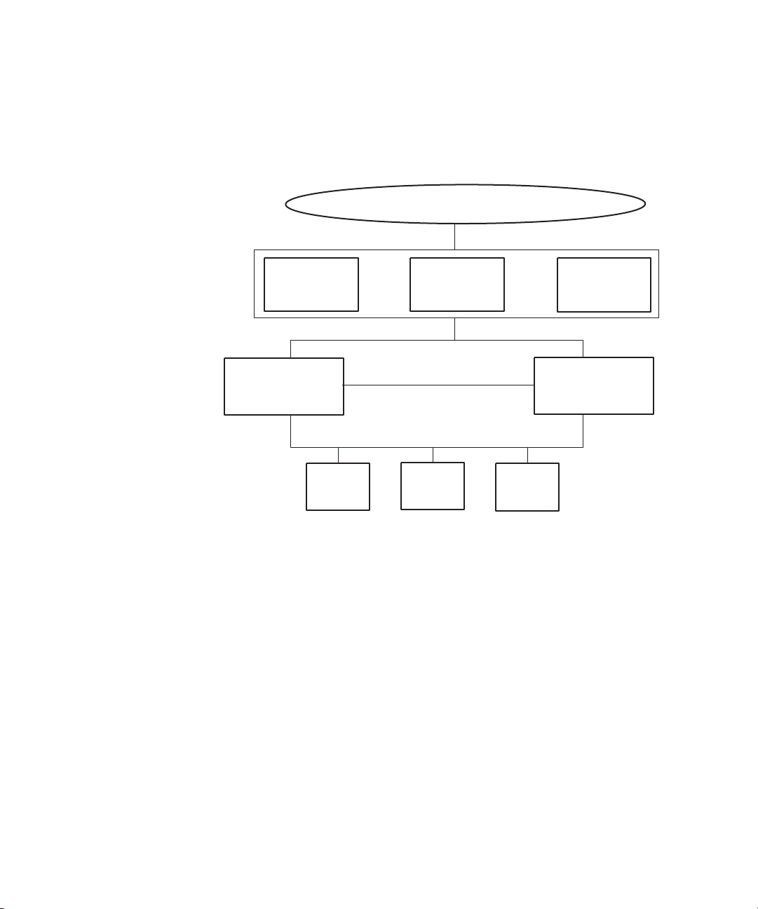
FibreChannel
Intranet
Private Network
Disk #1
Quorum
4GB
Interplay Server
(virtual)
11.22.33.201
MSDTC
11.22.33.202
Failover Cluster
11.22.33.200
Node #1
Intranet: 11.22.33.44
Private: 10.10.10.10
Node #2
Intranet: 11.22.33.45
Private: 10.10.10.11
Disk #2
MSDTC
5GB
Disk #3
Database
925GB +
Cluster Group
Resource groups
Clustered
services
Disk resources
(shared disks)
The following diagram illustrates the components of a cluster group, including sample IP
addresses. For a list of required IP addresses and node names, see
Network Names” on page 43.
“List of IP Addresses and
How Server Failover Works
14
If you are already using clusters, the Avid Interplay Engine will not interfere with your
n
current
setup.
Server failover works on two different levels:
• Failover in case of hardware failure
• Failover in case of network failure
Hardware Failover Process
When the Microsoft cluster service is running on both systems and the server is deployed in
cluster mode, the Interplay Engine and its accompanying services are exposed to users as a
virtual server. To clients, connecting to the clustered virtual Interplay Engine appears to be
the same process as connecting to a single, physical machine. The user or client application
does not know which node is actually hosting the virtual server.
Page 15

Server Failover Configurations
When the server is online, the resource monitor regularly checks its availability and
automatically restarts the server or initiates a failover to the other node if a failure is
detected. The exact behavior can be configured using the Windows Cluster Administrator
console. Because clients connect to the virtual network name and IP address, which are also
taken over by the failover node, the impact on the availability of the server is minimal.
Network Failover Process
The cluster resource monitors one primary network that connects the virtual server to the
intranet. If the primary network fails, the virtual server (and thus both cluster nodes) will go
offline. Avid supports a configuration that uses connections to two public networks (VLAN
10 and VLAN 20) on a single switch. However, in this configuration Windows clustering
technology binds multiple virtual IP addresses to VLAN 10 as the primary network, and if
VLAN 10 fails the virtual server will go offline.
For a high degree of protection against network outages, Avid supports a configuration that
uses two network switches, each connected to a shared primary network (VLAN 30) and
protected by a failover protocol. If one network switch fails, the virtual server remains
online through the other VLAN 30 network and switch.
These configurations are described in the next section.
Server Failover Configurations
There are three supported configurations for integrating a failover cluster into an existing
network:
• A cluster in an Avid Unity ISIS environment that is integrated into the intranet through
two layer-3 switches (VLAN 30 in Zone 3). This “redundant-switch” configuration
protects against both hardware and network outages and thus provides a higher level of
protection than the dual-connected configuration.
• A cluster in an Avid Unity ISIS environment that is integrated into the intranet through
two public networks (VLAN 10 and VLAN 20 in Zone 1). This “dual connected”
configuration protects against hardware outages and network outage on VLAN 20 but,
because only VLAN 10 is monitored, does not protect against a outage on the other
network.
• A cluster in an Avid Unity MediaNetwork environment that is integrated into the
intranet through a single public network. This configuration protects against hardware
outages.It relies on a single public network, and so does not protect against a network
outage.
15
Page 16
1 Automatic Server Failover Introduction
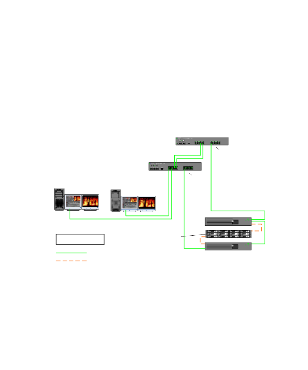
Two-node cluster in an
Avid Unity ISIS environment
(redundant switch)
Infortrend
cluster
shared-storage
RAID array
Interplay clients
Intranet
LEGEND
Fibre connection
1 GB Ethernet connection
Interplay Engine - Cluster Node
Interplay Engine - Cluster Node
Private network
for heartbeat
Avid Network Switch 1
running VRRP/HSRP
Avid Network Switch 2
running VRRP/HSRP
VLAN 30
VLAN 30
Redundant-Switch Configuration
The following diagram illustrates the failover cluster architecture for an Avid Unity ISIS
environment that uses two layer-3 switches. These switches are configured for failover
protection through either HSRP (Hot Standby Router Protocol) or VRRP (Virtual Router
Redundancy Protocol). The cluster nodes are connected to two subnets (VLAN 30), each on
a different switch. If one of the VLAN 30 networks fails, the virtual server remains online
through the other VLAN 30 network and switch.
This guide does not describe how to configure redundant switches for an Avid Unity ISIS
n
media network. Configuration information is included in the Avid Unity ISIS Switch
Reference Guide, which is available for download from the Avid Customer Support
Knowledge Base at
www.avid.com\onlinesupport.
16
Page 17
The following table describes what happens in the redundant-switch configuration as a result
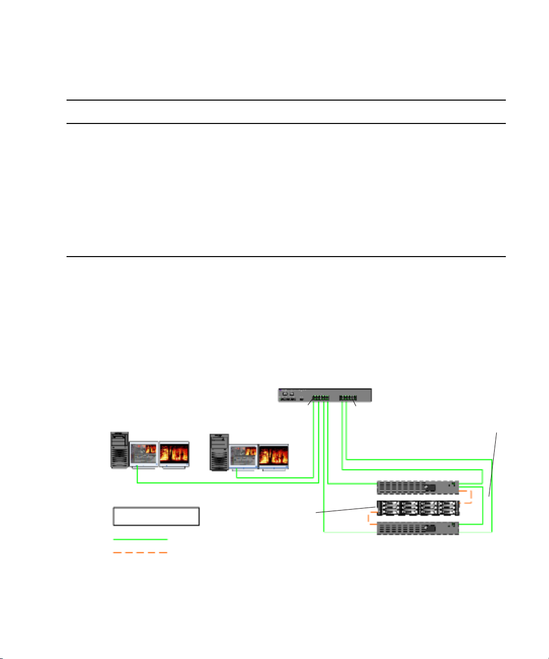
Two-node cluster in an Avid Unity
ISIS environment (dual-connected)
Interplay Engine - Cluster Node
Infortrend
cluster
shared-storage
RAID array
Interplay Engine - Cluster Node
Interplay clients
Intranet
Avid Network Switch
Private network
for heartbeat
LEGEND
Fibre connection
1 GB Ethernet connection
VLAN 20
VLAN 10
of an outage:
Type of Outage Result
Server Failover Configurations
Hardware (CPU, network adapter,
memory, cable, power supply) fails
The cluster detects the outage and triggers failover to the remaining node.
The Interplay Engine is still accessible.
Network switch 1 (VLAN 30) fails External switches running VRRP/HSRP detect the outage and make the
gateway available as needed.
The Interplay Engine is still accessible.
Network switch 2 (VLAN 30) fails External switches running VRRP/HSRP detect the outage and make the
gateway available as needed.
The Interplay Engine is still accessible.
Dual-Connected Configuration
The following diagram illustrates the failover cluster architecture for an Avid Unity ISIS
environment. In this environment, each cluster node is “dual-connected” to the network
switch: one network interface is connected to the VLAN 10 subnet and the other is
connected to the VLAN 20 subnet. In this configuration Windows clustering technology
binds multiple virtual IP addresses to VLAN 10 as the primary network, and if VLAN 10
fails the virtual server goes offline.
17
Page 18
1 Automatic Server Failover Introduction
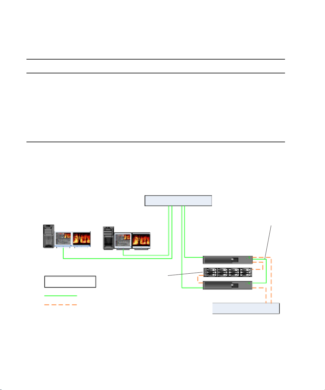
Two-node cluster in an Avid Unity
MediaNetwork environment
Interplay Engine - Cluster Node
Infortrend
cluster
shared-storage
RAID array
Interplay Engine - Cluster Node
Interplay clients
Intranet
Network Switch
Private network
for heartbeat
Fibre Switch
LEGEND
Fibre connection
1 GB Ethernet connection
The following table describes what happens in the dual-connected configuration as a result
of an outage:
Type of Outage Result
Hardware (CPU, network adapter,
memory, cable, power supply) fails
Left ISIS VLAN (VLAN10,
primary network) fails
The cluster detects the outage and triggers failover to the remaining node.
The Interplay Engine is still accessible.
The cluster detects the outage and triggers failover but detects that the
second node is also disconnected from the left network, and both clusters
fail.
The Interplay Engine is not accessible.
Right ISIS VLAN (VLAN 20) fails The Interplay Engine is still accessible through the left network.
Avid Unity MediaNetwork Configuration
The following diagram illustrates the failover cluster architecture for an Avid Unity
MediaNetwork environment. In this environment, each cluster node is connected to a
network switch through a single public network.
18
Page 19

The following table describes what happens in the MediaNetwork configuration as a result
of an outage:
Type of Outage Result
Server Failover Requirements
Hardware (CPU, network adapter,
memory, cable, power supply) fails
Network switch fails The cluster detects the outage and triggers failover but detects that the
The cluster detects the outage and triggers failover to the remaining node.
The Interplay Engine is still accessible.
second node is also disconnected from the network, and both clusters fail.
The Interplay Engine is not accessible.
Server Failover Requirements
You should make sure the server failover system meets the following requirements.
Hardware
A dual-server failover cluster-capable system with an Infortrend® cluster shared-storage
RAID disk set is needed. The automatic server failover system was developed on and tested
with the following:
• Intel Server Chassis SR2500 Packaged Cluster, which is the recommended hardware:
http://www.intel.com/design/servers/chassis/sr2500/
• Intel Server Chassis SR2400 Packaged Cluster:
http://www.intel.com/design/servers/chassis/sr2400/
The servers in a cluster are connected using one or more cluster shared-storage buses and
one or more physically independent networks acting as a heartbeat.
Server Software
Two licenses of Windows Server 2003 Enterprise Edition or Windows Server 2003
Datacenter Edition are needed.
Space Requirements
The default disk configuration for the cluster shared RAID array is as follows:
• Quorum disk - 4GB
•MSDTC disk - 5GB
• Database disk - 925GB or larger
19
Page 20

1 Automatic Server Failover Introduction
Antivirus Software
You can run antivirus software on a cluster, if the antivirus software is cluster-aware. For
information about cluster-aware versions of your antivirus software, contact the antivirus
vendor. If you are running antivirus software on a cluster, make sure you exclude these
locations from the virus scanning: Q:\ (Quorum disk), C:\Windows\Cluster, and
S:\Workgroup_Databases (database).
Functions You Need To Know
Before you set up a cluster in an Avid Interplay environment, you should be familiar with
the following functions:
• Microsoft Windows Active Directory domains and domain users
• Microsoft Windows clustering (current version, as there are changes from prior version)
• Disk configuration (format, partition, naming)
• Network configuration
Installing the Failover Hardware Components
A failover cluster system includes the following components:
• Two Interplay Engine nodes or two Interplay Archive nodes (two SR2400 servers or
two SR2500 servers)
• One Infortrend cluster shared-storage RAID array (one Infortrend A16F-R221 or one
Infortrend A16F-R2431)
The following topics provide information about installing the failover hardware components
for the supported configurations:
• “SR2400 Slot Locations” on page 21
• “SR2500 Slot Locations (for Infortrend A16F-R221)” on page 22
• “SR2500 Slot Locations (for Infortrend A16F-R2431)” on page 23
• “Failover Cluster Connections: Avid Unity ISIS, Redundant-Switch Configuration,
Infortrend A16F-221” on page 24
• “Failover Cluster Connections: Avid Unity ISIS, Redundant-Switch Configuration,
Infortrend A16F-R2431” on page 27
• “Failover Cluster Connections: Avid Unity ISIS, Dual-Connected Configuration,
Infortrend A16F-R221” on page 29
• “Failover Cluster Connections: Avid Unity ISIS, Dual-Connected Configuration,
Infortrend A16F-R2431” on page 32
20
Page 21
• “Failover Cluster Connections: Avid Unity MediaNetwork, Infortrend A16F-R221” on
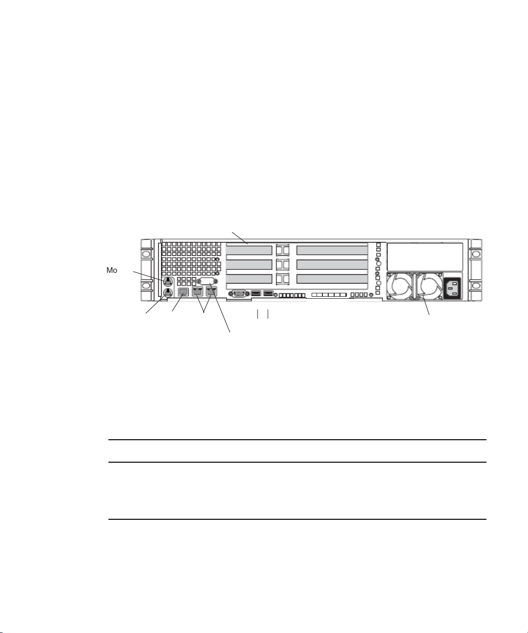
PCI slots
Serial A to F/C switch if needed
SCSI B
Video
USB
1
2
SR2400 Back Panel
Mouse
Keyboard
RJ 45 to
serial B
Power supply
Slot 2
Slot 1
Slot 3
Small form factor slots not used
1 GB
Ethernet
page 34
• “Failover Cluster Connections: Avid Unity MediaNetwork, Infortrend A16F-R2431” on
page 37
SR2400 Slot Locations
The SR2400 is supported as a server for the Interplay applications. This section describes
the slot locations that are specific to the Interplay components in a cluster configuration.
Use the following figure and table as guides to configuring an SR2400 system.
Installing the Failover Hardware Components
n
On the SR2400, all boards must be installed starting in the top slot, and the second board
must be in the middle slot. The second board cannot be in the bottom slot with the middle
slot left open.
SR2400 Back Panel Configuration for Avid Unity Environment
Slot Avid Unity ISIS Avid Unity MediaNetwork
3 Intel Pro 1000MT ATTO
®
2 QLogic
1 Empty Intel Pro 1000MT
a. Unity MediaNetwork environment: the Pro 1000MT card is shipped in slot 3 (top). You must move the
card to slot 1 (bottom) and install the ATTO card in slot 3 (top). The Pro 1000MT is not used in an Unity
MediaNetwork environment.
Card QLogic Card
a
21
Page 22
1 Automatic Server Failover Introduction
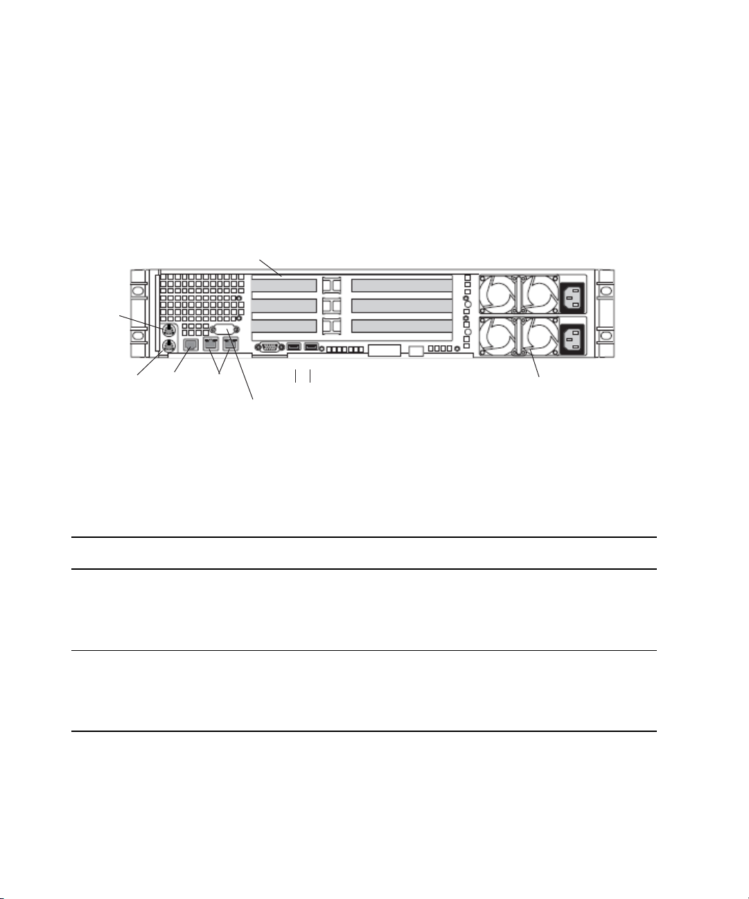
PCI-X slots
Power supplies
Serial A to F/C switch if needed
Video
USB
1
2
SR2500 Back Panel
Mouse
Keyboard
RJ 45 to
serial B
Primary power
supply on bottom
Slot 2
Slot 1
Slot 3
PCIe slots (small form factor)
1 GB
Ethernet
Slot 2
Slot 1
SR2500 Slot Locations (for Infortrend A16F-R221)
The SR2500 is supported as a server for the Interplay applications. This section describes
the slot locations that are specific to the Interplay components in a cluster configuration that
uses the Infortrend model A16F-R221shared-storage RAID array.
Use the following figure and table as guides to configuring an SR2500 system.
n
SR2500 Back Panel Configuration for Avid Unity Environment
Slot Type Slot Avid Unity ISIS Avid Unity MediaNetwork
PCI-X 3 Empty ATTO
PCIe NA NA NA
a. The SR2500 server might ship with the QLogic card in PCI-X slot 2 (middle). You must move the QLogic card to
22
It is important to match the slot locations in the following tables because they match the
order that the drivers are loaded on the SR2500 Recovery DVDs.
2 Empty Empty
a
1QLogic Card
to Infortrend A16F-R221
2 Intel Pro 1000PT Intel Pro 1000PT
1 Empty Empty
PCI-X slot 1 (bottom), because this configuration matches the order that the drivers are loaded on the SR2500
Recovery DVDs.
QLogic Carda to Infortrend A16F-R221
Page 23
Installing the Failover Hardware Components
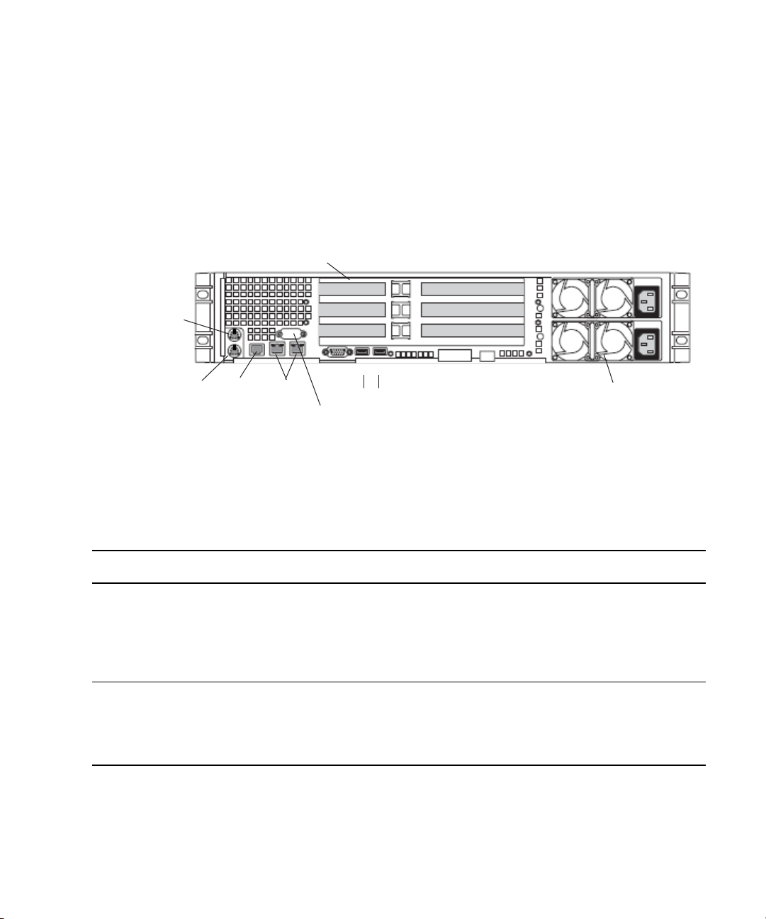
PCI-X slots
Power supplies
Serial A to F/C switch if needed
Video
USB
1
2
SR2500 Back Panel
Mouse
Keyboard
RJ 45 to
serial B
Primary power
supply on bottom
Slot 2
Slot 1
Slot 3
PCIe slots (small form factor)
1 GB
Ethernet
Slot 2
Slot 1
SR2500 Slot Locations (for Infortrend A16F-R2431)
The SR2500 is supported as a server for the Interplay applications. This section describes
the slot locations that are specific to the Interplay components in a cluster configuration that
uses the Infortrend A16F-R2431 shared-storage RAID array.
Use the following figure and table as guides to configuring an SR2500 system.
SR2500 Back Panel Configuration for Avid Unity Environment
Slot Type Slot Avid Unity ISIS Avid Unity MediaNetwork
PCI-X 3 Empty Empty
PCIe NA NA NA
It is important to match the slot locations in the following tables because they match the
n
order that the drivers are loaded on the SR2500 Recovery DVDs.
2 Empty Empty
1 ATTO FC-41XS to
Infortrend A16F-R2431
ATTO FC-41XS to
Infortrend A16F-R2431
2 Intel Pro 1000PT Intel Pro 1000PT
1 Empty ATTO FC-41EL to MediaNetwork
23
Page 24

1 Automatic Server Failover Introduction
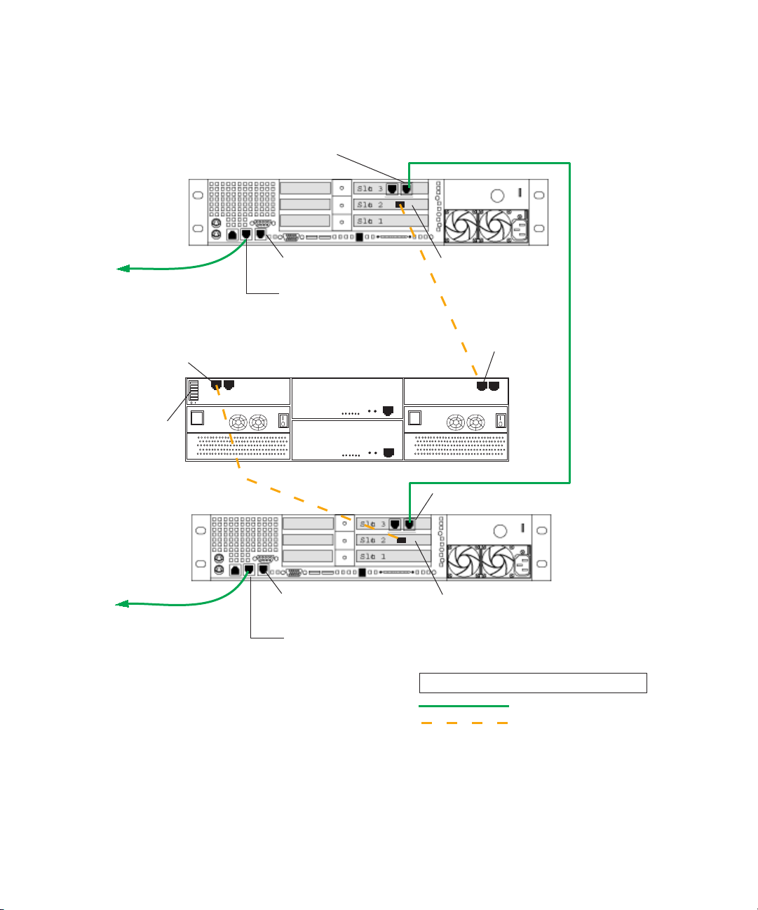
Failover Cluster Connections: Avid Unity ISIS, Redundant-Switch Configuration, Infortrend A16F-221
Make the following cable connections to add a failover cluster to an Avid Unity ISIS
environment, using the redundant-switch configuration with an Infortrend A16F-R221
RAID array:
• First cluster node:
- Left on-board network interface connector to layer-3 switch 1 (VLAN 30)
- QLogic card connector to RAID array, Fibre Channel 1 left connector
• Second cluster node:
- Left on-board network interface connector to layer-3 switch 2 (VLAN 30)
- QLogic card connector to RAID array, Fibre Channel 0 left connector
• Right connector on PCI adapter network interface in the first cluster node to right
connector on PCI adapter network interface in second cluster node (private network for
heartbeat)
• All switches on the cluster shared-storage RAID array are in the default “enable”
position (left).
24
You can implement this configuration using either SR2400 servers or SR2500 servers. The
following illustrations show the connections for each type of server.
Page 25
Private network
for heartbeat
PCI adapter network interface
right connector
QLogic card
Right on-board
network interface
Left on-board
network interface
PCI adapter network interface
right connector
LEGEND
Fibre connection
1GB Ethernet connection
QLogic card
Interplay Engine
Cluster Node 1
Interplay Engine
Cluster Node 2
Right on-board
network interface
Left on-board
network interface
Cluster Shared-Storage RAID Array
Fibre Channel 1
left connector
Fibre Channel 0
left connector
FC CH0
FC CH1
All switches
set to default
“enabled” left
SR2400
Back Panel
SR2400
Back Panel
To Avid Network
Switch 1
To Avid Network
Switch 2
Installing the Failover Hardware Components
Failover Cluster Connections: Avid Unity ISIS, Redundant-Switch Configuration,
SR2400, Infortrend A16F-R221
25
Page 26
1 Automatic Server Failover Introduction
Private network
for heartbeat
PCI adapter network interface
right connector
To Avid Network
Switch 1
QLogic card
Right on-board
network interface
Left on-board
network interface
PCI adapter network interface right connector
LEGEND
Fibre connection
1GB Ethernet connection
QLogic card
Interplay Engine
Cluster Node 1
Interplay Engine
Cluster Node 2
Right on-board
network interface
Left on-board
network interface
Cluster Shared-Storage RAID Array
Fibre Channel 1
left connector
Fibre Channel 0
left connector
FC CH0
FC CH1
All switches
set to default
“enabled” left
SR2500
Back Panel
SR2500
Back Panel
Slot 3
Slot 2
Slot 1
To Avid Network
Switch 2
Failover Cluster Connections: Avid Unity ISIS Environment, Redundant-Switch
Configuration, SR2500, Infortrend A16F-R221
26
Page 27

Installing the Failover Hardware Components
Failover Cluster Connections: Avid Unity ISIS, Redundant-Switch Configuration, Infortrend A16F-R2431
Make the following cable connections to add a failover cluster to an Avid Unity ISIS
environment, using the redundant-switch configuration with an Infortrend A16F-R2431
RAID array:
• First cluster node:
- Left on-board network interface connector to layer-3 switch 1 (VLAN 30)
- ATTO 41XS card connector to RAID array, Fibre Channel 0 top-left connector
• Second cluster node:
- Left on-board network interface connector to layer-3 switch 2 (VLAN 30)
- ATTO 41XS card connector to RAID array, Fibre Channel 1 bottom-right
connector
• Right connector on PCI adapter network interface in the first cluster node to right
connector on PCI adapter network interface in second cluster node (private network for
heartbeat)
• All switches on the cluster shared-storage RAID array are in the default “enable”
position (left)
You can implement this configuration using SR2500 servers. The following illustration
shows the connections for these servers.
27
Page 28
1 Automatic Server Failover Introduction
Failover Cluster Connections: Avid Unity ISIS, Redundant-Switch Configuration,
SR2500, Infortrend A16F-R2431
PCI adapter network interface
right connector
Interplay Engine
Cluster Node 1
To Av id Network
Switch 1
All switches
set to default
“enabled” left
Interplay Engine
Cluster Node 2
Fibre Channel 0
top left connector
01
FC CH0
l
Be sure
both PSUs have same mark
Fibre Channel 1
bottom right connector
Slot 3
Slot 2
Slot 1
Right on-board
network interface
Left on-board
network interface
Cluster Shared-Storage RAID Array
BBU Status
Ctrl Status
1.
2.
C Dirty
3.
Temp
CH0 CH1
CH0 CH1
123
COM1CO M2
456
BBU Status
Ctrl Status
1.
2.
C Dirty
3.
Temp
123
COM1CO M2
45
6
ATTO 41XS card
ES A16F-R2431-1
BBU Link
4.
5.
Hist Bay
Drv Bay
6.
Service Only
l
ES A16F-R2431-1
BBU Link
4.
5.
Hist Bay
Drv Bay
6.
Service Only
Be sure
both PSUs have same mark
PCI adapter network interface right connector
SR2500
Back Panel
Private network
for heartbeat
SR2500
Back Panel
28
To Av id Network
Switch 2
Right on-board
network interface
Left on-board
network interface
ATTO 41XS card
LEGEND
1GB Ethernet connection
Fibre connection
Page 29

Installing the Failover Hardware Components
Failover Cluster Connections: Avid Unity ISIS, Dual-Connected Configuration, Infortrend A16F-R221
Make the following cable connections to add a failover cluster to an Avid Unity ISIS
environment, using the dual-connected configuration with an Infortrend A16F-R221RAID
array:
• First cluster node:
- Left on-board network interface connector to ISIS left subnet (VLAN 10)
- Right on-board network interface connector to ISIS right subnet (VLAN 20)
- QLogic card connector to RAID array, Fibre Channel 1 left connector
• Second cluster node:
- Left on-board network interface connector to ISIS left subnet (VLAN 10)
- Right on-board network interface connector to ISIS right subnet (VLAN 20)
- QLogic card connector to RAID array, Fibre Channel 0 left connector
• Right connector on PCI adapter network interface in the first cluster node to right
connector on PCI adapter network interface in second cluster node (private network for
heartbeat)
• All switches on the cluster shared-storage RAID array are in the default “enable”
position (left)
You can implement this configuration using either SR2400 servers or SR2500 servers. The
following illustrations show the connections for each type of server.
29
Page 30
1 Automatic Server Failover Introduction
Private network
for heartbeat
PCI adapter network interface
right connector
To ISIS right
subnet
To ISIS left
subnet
To ISIS right subnet
To ISIS left
subnet
QLogic card
Right on-board
network interface
Left on-board
network interface
PCI adapter network interface
right connector
LEGEND
Fibre connection
1GB Ethernet connection
QLogic card
Interplay Engine
Cluster Node 1
Interplay Engine
Cluster Node 2
Right on-board
network interface
Left on-board
network interface
Cluster Shared-Storage RAID Array
Fibre Channel 1
left connector
Fibre Channel 0
left connector
FC CH0
FC CH1
All switches
set to default
“enabled” left
SR2400
Back Panel
SR2400
Back Panel
Failover Cluster Connections: Avid Unity ISIS, Dual-Connected Configuration,
SR2400, Infortrend A16F-R221
30
Page 31

Failover Cluster Connections: Avid Unity ISIS, Dual-Connected Configuration,
Private network
for heartbeat
PCI adapter network interface
right connector
To ISIS right
subnet
To ISIS left
subnet
To ISIS right subnet
To ISIS left
subnet
QLogic card
Right on-board
network interface
Left on-board
network interface
PCI adapter network interface right connector
LEGEND
Fibre connection
1GB Ethernet connection
QLogic card
Interplay Engine
Cluster Node 1
Interplay Engine
Cluster Node 2
Right on-board
network interface
Left on-board
network interface
Cluster Shared-Storage RAID Array
Fibre Channel 1
left connector
Fibre Channel 0
left connector
FC CH0
FC CH1
All switches
set to default
“enabled” left
SR2500
Back Panel
SR2500
Back Panel
Slot 3
Slot 2
Slot 1
SR2500, Infortrend A16F-R221
Installing the Failover Hardware Components
31
Page 32

1 Automatic Server Failover Introduction
Failover Cluster Connections: Avid Unity ISIS, Dual-Connected Configuration, Infortrend A16F-R2431
Make the following cable connections to add a failover cluster to an Avid Unity ISIS
environment, using the dual-connected configuration with an Infortrend A16F-R2431 RAID
array:
• First cluster node:
- Left on-board network interface connector to ISIS left subnet (VLAN 10)
- Right on-board network interface connector to ISIS right subnet (VLAN 20)
- ATTO 41XS card connector to RAID array, Fibre Channel 0 top-left connector
• Second cluster node:
- Left on-board network interface connector to ISIS left subnet (VLAN 10)
- Right on-board network interface connector to ISIS right subnet (VLAN 20)
- ATTO 41XS card connector to RAID array, Fibre Channel 1 bottom-right
connector
• Right connector on PCI adapter network interface in the first cluster node to right
connector on PCI adapter network interface in second cluster node (private network for
heartbeat)
32
• All switches on the cluster shared-storage RAID array are in the default “enable”
position (left)
You can implement this configuration using SR2500 servers. The following illustration
shows the connections for these servers.
Page 33

Failover Cluster Connections: Avid Unity ISIS, Dual-Connected Configuration,
Private network
for heartbeat
PCI adapter network interface
right connector
To ISIS right
subnet
To ISIS left
subnet
To ISIS right subnet
To ISIS left
subnet
ATTO 41XS card
Right on-board
network interface
Left on-board
network interface
PCI adapter network interface right connector
LEGEND
Fibre connection
1GB Ethernet connection
ATTO 41XS card
Interplay Engine
Cluster Node 1
Interplay Engine
Cluster Node 2
Right on-board
network interface
Left on-board
network interface
Cluster Shared-Storage RAID Array
Fibre Channel 1
bottom right connector
Fibre Channel 0
top left connector
FC CH0
All switches
set to default
“enabled” left
SR2500
Back Panel
SR2500
Back Panel
Slot 3
Slot 2
Slot 1
l
Be sure
both PSUs have same mark
l
Be sure
both PSUs have same mark
ES A16F-R2431-1
123
456
COM1CO M2
BBU Status
Service Only
CH0 CH1
ES A16F-R2431-1
123
45
Ctrl Status
6
COM1CO M2
BBU Status
Service Only
CH0 CH1
C Dirty
Temp
BBU Link
Hist Bay
Drv Bay
1.
2.
3.
4.
5.
6.
Ctrl Status
C Dirty
Temp
BBU Link
Hist Bay
Drv Bay
1.
2.
3.
4.
5.
6.
01
SR2500, Infortrend A16F-R2431
Installing the Failover Hardware Components
33
Page 34

1 Automatic Server Failover Introduction
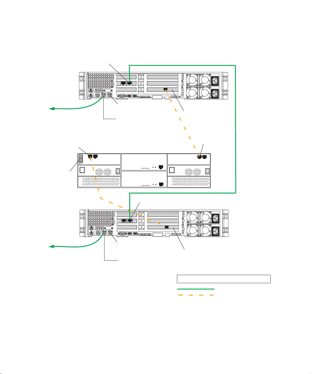
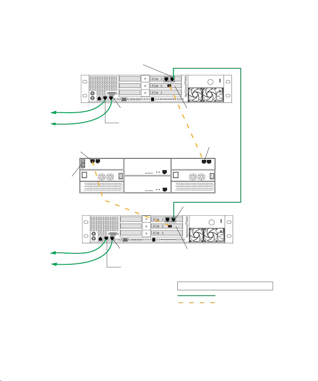
Failover Cluster Connections: Avid Unity MediaNetwork, Infortrend A16F-R221
Make the following cable connections to add a failover cluster to an Unity MediaNetwork
environment, using the Infortrend A16F-R221RAID array:
• First cluster node:
®
- Left on-board network interface connector to Ethernet
network switch
- QLogic card connector to RAID array, Fibre Channel 1 left connector
- ATTO card connector to Unity MediaNetwork FC switch
• Second cluster node:
- Left on-board network interface connector to Ethernet public network on the Avid
network switch
- QLogic card connector to RAID array, Fibre Channel 0 left connector
- ATTO card connector to Unity MediaNetwork FC switch
• Right on-board network interface connector on the first cluster node to right on-board
network interface connector on the second cluster node (private network for heartbeat)
public network on the Avid
• All switches on the cluster shared-storage RAID array are in the default “enable”
position (left)
SR2400 servers ship with an Intel Pro 1000 MT card in slot 3 (top). You need to move this
n
card to slot 1 (bottom). Then add an ATTO host bus adapter in slot 3 (top). See
Slot Locations” on page 21.
You can implement this configuration using either SR2400 servers or SR2500 servers. The
following illustrations show the connections for each type of server.
“SR2400
34
Page 35

Private network
for heartbeat
ATTO card
ATTO card
To Ethernet
Public Network
Right on-board
network interface
Left on-board
network interface
To MediaNetwork
FC switch
LEGEND
Fibre connection
1GB Ethernet connection
To
MediaNetwork
FC switch
Interplay Engine
Cluster Node 1
Interplay Engine
Cluster Node 2
Right on-board
network interface
Left on-board
network interface
To Ethernet
Public Network
QLogic card
QLogic card
PCI adapter network interface - not used
PCI adapter network interface - not used
Fibre Channel 1
left connector
Fibre Channel 0
left connector
FC CH0
FC CH1
All switches set to
default “enabled” left
Cluster Shared-Storage RAID Array
SR2400
Back Panel
SR2400
Back Panel
Installing the Failover Hardware Components
Failover Cluster Connections: Avid Unity MediaNetwork, SR2400, Infortrend
A16F-R221
35
Page 36

1 Automatic Server Failover Introduction
Slot 3
Slot 1
Private network
for heartbeat
ATTO card
ATTO card
To Ethernet
public network
Right on-board
network interface
Left on-board
network interface
To MediaNetwork
FC switch
LEGEND
Fibre connection
1GB Ethernet connection
To
MediaNetwork
FC switch
Interplay Engine
Cluster Node 1
Interplay Engine
Cluster Node 2
Right on-board
network interface
Left on-board
network interface
To Ethernet
public network
QLogic card
QLogic card
Fibre Channel 1
left connector
Fibre Channel 0
left connector
FC CH0
FC CH1
All switches set to
default “enabled” left
Cluster Shared-Storage RAID Array
SR2500
Back Panel
SR2500
Back Panel
PCI adapter network
interface - not used
Slot 2
Failover Cluster Connections: Avid Unity MediaNetwork, SR2500, Infortrend
A16F-R221
36
Page 37

Installing the Failover Hardware Components
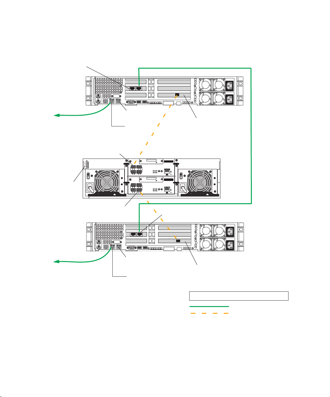
Failover Cluster Connections: Avid Unity MediaNetwork, Infortrend A16F-R2431
Make the following cable connections to add a failover cluster to an Unity MediaNetwork
environment.
• First cluster node:
- Left on-board network interface connector to Ethernet public network on the Avid
network switch
- ATTO 41XS card connector to RAID array, Fibre Channel 0 top-left connector
- ATTO 41EL card connector to Unity MediaNetwork FC switch
• Second cluster node:
- Left on-board network interface connector to Ethernet public network on the Avid
network switch
- ATTO 41XS card connector to RAID array, Fibre Channel 1 bottom-right
connector
- ATTO 41EL card connector to Unity MediaNetwork FC switch
• Right on-board network interface connector on the first cluster node to right on-board
network interface connector on the second cluster node (private network for heartbeat)
• All switches on the cluster shared-storage RAID array are in the default “enable”
position (left)
You can implement this configuration using SR2500 servers. The following illustration
shows the connections for these servers.
37
Page 38

1 Automatic Server Failover Introduction
Failover Cluster Connections: Avid Unity MediaNetwork, SR2500, Infortrend
A16F-R2431
PCI adapter network
interface - not used
Interplay Engine
Cluster Node 1
To Ethernet
public network
All switches set to
default “enabled” left
To
MediaNetwork
FC switch
Interplay Engine
Cluster Node 2
Private network
for heartbeat
ATTO 41EL card
Slot 3
Slot 2
Slot 1
Right on-board
network interface
Left on-board
network interface
Fibre Channel 0
top left connector
01
l
Be sure
both PSUs have same mark
ATTO 41EL card
CH0 CH1
CH0 CH1
To MediaNetwork
FC switch
SR2500
Back Panel
ATTO 41XS card
Cluster Shared-Storage RAID Array
ES A16F-R2431-1
BBU Status
Ctrl Status
BBU Link
1.
4.
2.
5.
C Dirty
Hist Bay
Drv Bay
3.
6.
Temp
Service Only
123
COM1CO M2
456
BBU Status
Ctrl Status
BBU Link
1.
4.
2.
5.
C Dirty
Hist Bay
Drv Bay
3.
6.
Temp
123
COM1CO M2
45
6
ES A16F-R2431-1
Service Only
l
Be sure
both PSUs have same mark
Fibre Channel 1
bottom right connector
38
To Ethernet
public network
Right on-board
network interface
Left on-board
network interface
SR2500
Back Panel
ATTO 41XS card
LEGEND
1GB Ethernet connection
Fibre connection
Page 39

Clustering Terminology
Clustering is not always straightforward, so it is important that you get familiar with the
terminology of server clusters before you start. A good source of information is the
Microsoft Technology Center for Clustering Services under:
http://www.microsoft.com/windowsserver2003/technologies/clustering/default.mspx
Detailed architecture documentation can be found here:
http://www.microsoft.com/windowsserver2003/techinfo/overview/servercluster.mspx
Here is a brief summary of the major concepts and terms:
• Nodes: Individual computers in a cluster configuration.
• Cluster service: The group of components on each node that perform a cluster-specific
activity.
• Resource: Cluster components (hardware and software) that are managed by the cluster
service. Resources are physical hardware devices such as disk drives, and logical items
such as IP addresses and applications.
• Online resource: A resource that is available and is providing its service.
• Quorum resource: A special common cluster resource. This resource plays a critical
role in cluster operations.
Clustering Terminology
• Resource group: A collection of resources that are managed by the cluster service as a
single, logical unit.
39
Page 40

1 Automatic Server Failover Introduction
40
Page 41

2 Creating a Microsoft Failover Cluster
This chapter describes the processes for creating a Microsoft failover cluster for automatic
server failover. It is crucial that you follow the instructions given in this chapter completely,
otherwise the automatic server failover will not work.
This chapter covers the following topics:
• Server Failover Installation Overview
• Before You Begin the Server Failover Installation
• Preparing the Server for the Cluster Service
• Configuring the Cluster Service
• Configuring Rules for the Cluster Networks
• After Setting Up the Cluster
• Installing the Distributed Transaction Coordinator
Instructions for installing the Interplay Engine are provided in “Installing the Interplay
Engine for a Failover Cluster” on page 81.
Server Failover Installation Overview
Installation and configuration of the automatic server failover consists of the following
major tasks:
• Make sure that the network is correctly set up and that you have reserved IP host names
and static IP addresses (see “Before You Begin the Server Failover Installation” on page
42).
• Prepare the servers for the cluster service (see “Preparing the Server for the Cluster
Service” on page 46). This includes configuring the nodes for the network and
formatting the drives.
• Configure the cluster service (see “Configuring the Cluster Service” on page 60,
“Configuring Rules for the Cluster Networks” on page 68, and “After Setting Up the
Cluster” on page 71).
• Install the Distributed Transaction Coordinator (MSDTC group) (see “Installing the
Distributed Transaction Coordinator” on page 75).
Page 42

2 Creating a Microsoft Failover Cluster
• Install the Interplay Engine on both nodes (see “Installing the Interplay Engine for a
Failover Cluster” on page 81).
• Test the complete installation (see “Testing the Complete Installation” on page 102).
Do not install any other software on the cluster machines except the Interplay engine. For
n
example, Media Indexer software needs to be installed on a different server. For complete
installation instructions, see the Avid Interplay Software Installation and Configuration
Guide.
For more details about server clusters, see the Microsoft document “Guide to Creating and
Configuring a Server Cluster under Windows Server 2003,” available at:
http://www.microsoft.com/technet/prodtechnol/windowsserver2003/technologies/clustering
/confclus.mspx
Before You Begin the Server Failover Installation
Before you begin the installation process, you need to do the following:
• Make sure all cluster hardware connections are correct. See “Installing the Failover
Hardware Components” on page 20.
42
• Make sure that the facility has a network that is qualified to run Active Directory and
DNS services.
• Determine the subnet mask, the gateway, DNS, and WINS server addresses on the
network.
• Install and set up an Avid Unity client on both servers. See the Avid Unity
MediaNetwork File Manager Setup Guide or the Avid Unity ISIS System Setup Guide.
• Create or select two domain user accounts:
- Cluster Service Account (Server Execution User): Create or select an account
(sometimes called the cluster user account) that is used to start the cluster service
and is also used by the Interplay Engine service. This account must be a domain
user and it must be a unique name that will not be used for any other purpose. The
procedures in this document use sqauser as an example of a Cluster Service
Account. This account is automatically added to the Local Administrators group on
each node by the Interplay Engine software during the installation process.
The Server Execution User is critical to the operation of the Interplay Engine. If
necessary, you can change the name of the Server Execution User after the
installation. For more information, see “Troubleshooting the Server Execution
User Account” and “Re-creating the Server Execution User” in the Avid Interplay
Engine and Avid Interplay Archive Engine Administration Guide and the Interplay
ReadMe.
Page 43

Before You Begin the Server Failover Installation
For information on creating a cluster user account, see the Microsoft document
“Guide to Creating and Configuring a Server Cluster under Windows Server 2003.”
http://www.microsoft.com/technet/prodtechnol/windowsserver2003/technologies/c
lustering/confclus.mspx.
- Cluster Installation and Administration Account: Create or select a user account to
use during the installation process. This user account must be a domain user
account with privileges to add servers to the domain. Also use this account to log in
to and administer the system.
Do not use the same username and password for the Cluster Service Account and the
n
Cluster Installation Account. These accounts have different functions and require different
privileges.
• Create an Avid Unity user account with read and write privileges. This account is not
needed for the installation of Interplay Engine, but is required for the operation of
Interplay
of the Cluster Service Account.
• Make sure the network includes an Active Directory domain before you install or
configure the cluster.
• Reserve static IP addresses for all network interfaces and host names. See “List of IP
Addresses and Network Names” on page 43.
Engine. The user name and password must match the user name and password
List of IP Addresses and Network Names
You need to reserve IP host names and static IP addresses on the in-network DNS server
before you begin the installation process. The number of IP addresses you need depends on
your configuration:
• An Avid Unity ISIS environment with a redundant-switch configuration requires 5 IP
addresses
• An Avid Unity ISIS environment with a dual-connected configuration requires 8 IP
addresses
• An Avid Unity MediaNetwork environment requires 5 IP addresses.
The following table provides a list of example names that you can use when configuring the
cluster. The procedures in this chapter use these example names.
Make sure that these IP addresses are outside of the range that is available to DHCP so they
n
cannot automatically be assigned to other machines.
43
Page 44

2 Creating a Microsoft Failover Cluster
If your Active Directory domain or DNS includes more than one cluster, to avoid conflicts,
n
you need to make sure the cluster names, MSDTC names, and IP addresses are different for
each cluster.
All names must be valid and unique network host names.
n
IP Addresses and Node Names: ISIS Redundant-Switch Configuration
Node or Service Item Required Example Name Where Used
First Cluster Node • 1 Host Name
• 1 ISIS IP address - public
• 1 IP address - private
(Heartbeat)
Second Cluster Node • 1 Host Name
• 1 ISIS IP address - public
• 1 IP address - private
(Heartbeat)
Cluster service • 1 Network Name
(virtual host name)
• 1 ISIS IP address
MSDTC service —
Distributed Transaction
Coordinator
Interplay Engine
service
• 1 Network Name
(virtual host name)
• 1 ISIS IP address
• 1 Network Name
(virtual host name)
• 1 ISIS IP address - public
SECLUSTER1 See “Configuring the
Cluster Service on the
First Node” on page 61
and “Creating a Resource
Group for the Distributed
Transaction Coordinator”
on page 76.
SECLUSTER2 See “Configuring the
Cluster Service on the
Second Node” on page 66
and “Creating a Resource
Group for the Distributed
Transaction Coordinator”
on page 76.
SECLUSTER See “Configuring the
Cluster Service on the
First Node” on page 61.
CLUSTERMSDTC See “Assigning a Network
Name to the MSDTC
Group” on page 78.
SEENGINE See “Specifying the
Interplay Engine Details”
on page 85 and
“Specifying the Interplay
Engine Service Name” on
page 87.
44
Page 45

Before You Begin the Server Failover Installation
IP Addresses and Node Names: ISIS Dual-Connected Configuration
Node or Service Item Required Example Name Where Used
First Cluster Node • 1 Host Name
• 2 ISIS IP addresses - public
(one for left and one for right)
• 1 IP address - private
(Heartbeat)
Second Cluster Node • 1 Host Name
• 2 ISIS IP addresses - public
(one for left and one for right)
• 1 IP address - private
(Heartbeat)
Cluster service • 1 Network Name
(virtual host name)
• 1 ISIS IP address
MSDTC service —
Distributed Transaction
Coordinator
Interplay Engine
service
• 1 Network Name
(virtual host name)
• 1 ISIS IP address
• 1 Network Name
(virtual host name)
• 2 ISIS IP addresses - public
(one for left and one for right)
SECLUSTER1 See “Configuring the
Cluster Service on the
First Node” on page 61
and “Creating a Resource
Group for the Distributed
Transaction Coordinator”
on page 76.
SECLUSTER2 See “Configuring the
Cluster Service on the
Second Node” on page 66
and “Creating a Resource
Group for the Distributed
Transaction Coordinator”
on page 76.
SECLUSTER See “Configuring the
Cluster Service on the
First Node” on page 61.
CLUSTERMSDTC See “Assigning a Network
Name to the MSDTC
Group” on page 78.
SEENGINE See “Specifying the
Interplay Engine Details”
on page 85 and
“Specifying the Interplay
Engine Service Name” on
page 87.
45
Page 46

2 Creating a Microsoft Failover Cluster
IP Addresses and Node Names: MediaNetwork Configuration
Node or Service Item Required Example Name Where Used
First Cluster Node • 1 Host Name
• 1 MediaNetwork IP address public
• 1 IP address - private
(Heartbeat)
Second Cluster Node • 1 Host Name
• 1 MediaNetwork IP address public
• 1 IP address - private
(Heartbeat)
Cluster service • 1 Network Name
(virtual host name)
• 1 MediaNetwork IP address
MSDTC service —
Distributed Transaction
Coordinator
Interplay Engine
service
• 1 Network Name
(virtual host name)
• 1 MediaNetwork IP address
• 1 Network Name
(virtual host name)
• 1 MediaNetwork IP address public
SECLUSTER1 See “Configuring the
Cluster Service on the
First Node” on page 61
and “Creating a Resource
Group for the Distributed
Transaction Coordinator”
on page 76.
SECLUSTER2 See “Configuring the
Cluster Service on the
Second Node” on page 66
and “Creating a Resource
Group for the Distributed
Transaction Coordinator”
on page 76.
SECLUSTER See “Configuring the
Cluster Service on the
First Node” on page 61.
CLUSTERMSDTC See “Assigning a Network
Name to the MSDTC
Group” on page 78.
SEENGINE See “Specifying the
Interplay Engine Details”
on page 85 and
“Specifying the Interplay
Engine Service Name” on
page 87.
Preparing the Server for the Cluster Service
Before you configure the cluster service, you need to complete the tasks in the following
procedures:
• “Setting the QLogic HBA Link Speed” on page 47
• “Increasing the Boot Delay” on page 49
• “Setting the ATTO Link Speed” on page 49
• “Renaming the Local Area Network Interface on Each Node” on page 52
46
Page 47

• “Removing Unnecessary Windows Components” on page 51
• “Renaming the Local Area Network Interface on Each Node” on page 52
• “Configuring the Private Network Adapter on Each Node” on page 55
• “Configuring the Binding Order Networks on Each Node” on page 57
• “Configuring the Public Network Adapter on Each Node” on page 59
• “Joining Both Servers to the Active Directory Domain” on page 59
• “Configuring the Cluster Shared-Storage RAID Disks on Each Node” on page 59
Setting the QLogic HBA Link Speed
To avoid possible problems with the Infortrend RAID array (Model A16F-R221), Avid
recommends that you change the QLogic HBA link speed (data rate) from the default setting
to 2 Gbps. You need to specify this setting on both the SR2400 server and the SR2500
server. Change the setting by using the SAN Surfer utility on both nodes.
To set the QLogic HBA link speed:
1. On the first node, click Start, and select Programs > QLogic Management Suite > San
Surfer.
Preparing the Server for the Cluster Service
The San Surfer FC HBA Manager dialog box opens.
47
Page 48

2 Creating a Microsoft Failover Cluster
48
2. In the left pane, select Port 1.
3. Click the Settings tab.
4. In the HBA Port Settings section, click the arrow pointer for the Data Rate list and
change the default setting from Auto to 2
Gbps.
5. Click Save.
6. When prompted for a password, enter
config
and click OK.
7. On the other node, repeat steps 1 through 6.
8. Verify that the SAN Surfer data rate is set to 2 Gbps on both nodes.
Page 49

Increasing the Boot Delay
Increasing the the timeout value in the boot.ini file increases the time it takes for the server
to boot. This boot delay might avoid a problem if the Infortrend requires a longer than usual
time for a self-test and initializing. If a server boots before the Infortrend is ready, the cluster
might fail.
Avid recommends that you offset the startup time of each node’s operating system (see
“Setting the Startup Times on Each Node” on page 72).
To increase the timeout value in the boot.ini file:
1. Start the first node and log in to Windows.
2. At the command prompt, type the following command and press Enter:
bootcfg /timeout 60
This command changes the boot timeout delay to 60 seconds, after which the default
operating system is loaded.
3. Repeat these steps on the second node, but set the timeout delay to 120 seconds.
Setting the ATTO Link Speed
Preparing the Server for the Cluster Service
To avoid possible problems with the Infortrend RAID array (Model A16F-R2431), Avid
recommends that you change the ATTO link speed (data rate) from the default setting to 4
Gbps. You need to specify this setting on both the SR2400 server and the SR2500 server.
Change the setting by using the ATTO Configuration Tool on both nodes.
To set the ATTO link speed:
1. On the first node, click Start, and select Programs > ATTO Configuration Tool >
Configuration Tool.
The ATTO Configuration Tool dialog box opens.
49
Page 50

2 Creating a Microsoft Failover Cluster
50
2. In the left pane, navigate to the appropriate channel on your host adapter.
The NVRAM tab opens.
3. Click the arrow pointer for the Data Rate list and change the default setting from Auto
Gb/sec.
to 4
4. Click Commit.
5. Reboot the system.
6. Open the Configuration tool again and verify that the Data Rate is set to 4 Gb/sec.
7. On the other node, repeat steps 1 through 6.
Page 51

Preparing the Server for the Cluster Service
Removing Unnecessary Windows Components
You need to remove some unnecessary Windows components before you configure the
cluster service. Which components you remove depends on the type of cluster you are
configuring.
• For a cluster that will be used as an Interplay Engine, remove the following from each
server:
- Internet Information Services (IIS)
- IIS-Admin
- Internet Explorer Enhanced Security Configuration
- Microsoft SQL Native Client
• For a cluster that will be used as an Interplay Archive Engine, remove the following
from each server:
- Internet Information Services (IIS)
- IIS-Admin
- Internet Explorer Enhanced Security Configuration
Microsoft SQL Native Client is required for SGL archive solutions and should be correctly
n
installed and configured before creating a cluster that will be used as an Archive Engine.
To remove unnecessary Windows components:
1. On one of the servers, click Start and select Control Panel > Add or Remove Programs.
2. (Interplay Engine only) If Microsoft SQL Native Client is listed, select it and click
Change/Remove.
3. Click Add/Remove Windows Components.
a. If a box is checked for Internet Explorer Enhanced Security Configuration, click the
check box to remove the check.
b. Select Application Server and click Details.
c. If a box is checked for Internet Information Services (IIS), click the check to
remove the check.
d. Click OK, then click Next. At the end of the process, click Finish.
4. Repeat the procedure on the other server.
51
Page 52

2 Creating a Microsoft Failover Cluster
Renaming the Local Area Network Interface on Each Node
You need to rename the LAN interface on each node to appropriately identify each network.
Although you can use any name for the network connections, Avid suggests that you use the
naming conventions provided in the table in the following procedure.
Make sure you use the same name on both nodes. The names and network connections on
both nodes must match.
To rename the local area network connections:
1. Open the Network Connections window.
a. Click Start and select Control Panel.
b. Right-click Network Connections, and select Open.
The Network Connections window opens.
52
c
2. Right-click one of the listed network connections and select Rename.
You need to match the numbered connection with the appropriate device. For example,
you can start by determining which connection refers to the left on-board network
interface and select that connection.
Both nodes must use identical network interface names. Although you can use any
name for the network connections, Avid suggests that you use the naming conventions
provided in the following table.
3. Depending on your Avid Unity network and the device you selected, type a new name
for the network connection and press Enter.
Page 53

Preparing the Server for the Cluster Service
SR2400 back view
Right on-board network interface
Left on-board network interface
Right PCI adapter network interface
Left PCI adapter network interface
This illustration shows
Unity ISIS environment.
Use the following illustration and table for reference. The illustration uses an SR2400 in
an Avid Unity ISIS environment as an example.
Naming Network Connections
Network Interface
Left on-board network
interface
Right on-board network
interface
Left PCI adapter network
interface
Avid Unity ISIS
New Names
(Redundant-switch
configuration)
Public
This is a public network
connected to network
switch
Avid Unity ISIS
New Names
(Dual-connected
configuration)
Left-subnet number
This is a public network
connected to network
switch.
Avid Unity
MediaNetwork
New Names
Public
This is a public network
connected to network
switch
Use the subnet number of
the interface. The
examples in this document
use Left-74
Not used Right-subnet number
This is a public network
connected to network
switch.
Use the subnet number of
Private
This is a private network
used for the heartbeat
between the two servers in
the cluster
the interface. The
examples in this document
Not used (Disabled) Not used (Disabled) Not used (Disabled)
use Right-75.
53
Page 54

2 Creating a Microsoft Failover Cluster
Naming Network Connections (Continued)
Network Interface
Right PCI adapter network
interface.
4. Repeat steps 2 and 3 for each network connection.
The following Network Connections window shows the new names used in an Avid
Unity ISIS environment.
Avid Unity ISIS
New Names
(Redundant-switch
configuration)
Private
This is a private network
used for the heartbeat
between the two servers in
the cluster.
Avid Unity ISIS
New Names
(Dual-connected
configuration)
Private
This is a private network
used for the heartbeat
between the two servers in
the cluster.
Avid Unity
MediaNetwork
New Names
Not used (Disabled)
54
5. Close the Network Connections window.
Page 55

Preparing the Server for the Cluster Service
Select this check box.
All others are unchecked.
Configuring the Private Network Adapter on Each Node
To configure the private network adapter for the heartbeat connection:
1. Open the Network Connections window.
2. Right-click the Private network connection and select Properties.
The Private Properties dialog box opens.
3. On the General tab, click the Internet Protocol (TCP/IP) check box. Make sure all other
components are unchecked.
4. Select Internet Protocol (TCP/IP) and click Properties.
The Internet Protocol (TCP/IP) Properties dialog box opens.
55
Page 56

2 Creating a Microsoft Failover Cluster
Type the private IP
address for the node
you are configuring.
56
5. On the General tab of the Internet Protocol (TCP/IP) Properties dialog box:
a. Select “Use the following IP address.”
b. IP address: type the IP address for the Private network connection for the node you
are configuring. See “List of IP Addresses and Network Names” on page 43.
When performing this procedure on the second node in the cluster make sure you use the
n
static private IP addresses for that node. In this example, use 192. 168. 100. 2.
c. Subnet mask: type the subnet mask address
Make sure you use a completely different IP address scheme from the one used for the public
n
network.
d. Make sure the “Default gateway” and “Use the Following DNS server addresses”
text boxes are empty.
6. Click Advanced.
The Advanced TCP/IP Settings dialog box opens.
Page 57

Preparing the Server for the Cluster Service
7. On the DNS tab, make sure no values are defined and that the “Register this
connection’s addresses in DNS” and “Use this connection’s DNS suffix in DNS
registration” are not selected.
8. On the WINS tab, do the following:
t Make sure no values are defined in the WINS addresses area.
t Uncheck “Enable LMHOSTS Lookup”.
t Select “Disable NetBIOS over TCP/IP.”
9. Click OK.
A message might by displayed stating “This connection has an empty primary WINS
address. Do you want to continue?” Click Yes.
10. Repeat this procedure on the other node in the cluster, using the static private IP
addresses for that node.
Configuring the Binding Order Networks on Each Node
Repeat this procedure on each node and make sure the configuration matches on both nodes.
57
Page 58

2 Creating a Microsoft Failover Cluster
To configure the binding order networks:
1. On one node, open the Network Connections window.
2. Select Advanced > Advanced Settings.
3. In the Connections area, use the arrow controls to position the network connections in
the following order:
- For a redundant-switch configuration in an Avid Unity ISIS environment, use the
following order
-Public
-Private
- For a dual-connected configuration in an Avid Unity ISIS environment, use the
following order, as shown in the illustration:
-Right
-Left
-Private
- Local Area Connection 4
58
Page 59

Preparing the Server for the Cluster Service
- For an Avid Unity MediaNetwork environment use the following order:
-Public
-Private
4. Click OK.
5. Repeat this procedure on the other node and make sure the configuration matches on
nodes.
both
Configuring the Public Network Adapter on Each Node
Make sure you configure the IP address network interfaces for the Public Network Adapter
as you normally would. For examples of public network settings, see
and Network Names” on page 43.
Joining Both Servers to the Active Directory Domain
After configuring the network information, join the two servers to the Active Directory
domain. You can then use your domain credentials for the Cluster Installation Account (see
“Before You Begin the Server Failover Installation” on page 42).
“List of IP Addresses
Configuring the Cluster Shared-Storage RAID Disks on Each Node
Both nodes must have the same configuration for the cluster shared-storage RAID disk.
When you configure the disks on the second node, make sure the disks match the disk
configuration you set up on the first node.
Before you create the partitions on the cluster nodes, make sure the cluster shared-storage
n
RAID disks were pre-configured (mirror, stripe, etc.) by the vendor. Make sure the disks are
Basic and not Dynamic.
To configure the disks on each node:
1. Shut down the server node you are not configuring at this time.
2. Open the Disk Management tool.
3. Initialize the disks, if not already initialized, by right-clicking the disk and selecting
Initialize Disk.
4. Use Quick Format to configure the disks as partitions, using the following names and
drive letters:
- Quorum (Q:) 4GB
-MSDTC (R:) 5GB
- Database (S:) 925GB
59
Page 60

2 Creating a Microsoft Failover Cluster
Configure disks
as shown
The following illustration shows the required names and drive letters.
Configuring the Cluster Service
60
5. Verify you can access the disk and that it is working by creating a file and deleting it.
6. Shut down the first node and start the second node.
7. On the second node, assign drive letters and names. You do not need to format the disks.
a. Open the Disk Management tool. Right-click the partition, select Change Drive
Letter, and enter the appropriate letter. Repeat these actions for the other partitions.
b. Open My Computer. Select a drive, right-click, select Rename, and enter the
appropriate name. Repeat these actions for the other drives.
Take the following steps to configure the cluster service:
1. Turn off the second node.
2. Configure the first node using the New Server Cluster Wizard. See “Configuring the
Cluster Service on the First Node” on page 61
Page 61

3. Validate the cluster service installation on the first node. See “Validating the Cluster
Service on the First Node” on page 66.
4. Turn on the second node. Leave first node turned on.
5. Configure the second node using Add Cluster Computers Wizard. See “Configuring the
Cluster Service on the Second Node” on page 66.
Configuring the Cluster Service on the First Node
To configure the cluster service on the first node:
1. Turn off the server for the node you are not configuring at this time.
2. Make sure all storage devices are turned on.
3. Click Start and select All Programs > Administrative Tools > Cluster Administrator.
The Open Connection to Cluster dialog box opens.
Configuring the Cluster Service
4. Select “Create new cluster” from the Action menu.
5. Make sure you have the prerequisites to configure the cluster, as shown in the New
Server Cluster Wizard Welcome window.
6. Click Next.
7. In the Cluster Name and Domain dialog box, do the following:
- Domain: select the name of your Active Directory domain
- Cluster name: type the Cluster service name, for example SECLUSTER — see
“List of IP Addresses and Network Names” on page 43.
61
Page 62

2 Creating a Microsoft Failover Cluster
Type the Cluster
service name.
8. Click Next.
62
The Select Computer dialog box opens.
You might be prompted for an account. If so, use a domain user account, such as the Cluster
n
Installation Account referred to in
page 42. Do not use the Cluster Service Account (Service Execution User).
“Before You Begin the Server Failover Installation” on
Page 63

Configuring the Cluster Service
9. In the Select Computer dialog box, in the Computer name text box, type the Cluster
node host name of the first node.
For example, use SECLUSTER1. See “List of IP Addresses and Network Names” on
page 43.
10. Click Advanced.
The Advanced Configuration Options dialog box opens.
11. Select Advanced (minimum) configuration, and click OK.
12. Click Next.
63
Page 64

2 Creating a Microsoft Failover Cluster
Type the Cluster Service
Account user name.
The setup process analyzes the node for hardware or software problems that might cause
problems during installation. A warning icon displays next to “Checking Cluster
feasibility.” In this case, the warnings do not indicate a problem.
13. Click Next after the analyze is complete and the Task Complete bar is green.
14. In the IP Address dialog box, type the Interplay Engine service ISIS IP address for the
left side in the IP Address text box. See
page 43.
15. Click Next.
16. In the Cluster Service Account dialog box, type the cluster user name and password, and
select the domain.
This is the Cluster Service Account (Server Execution User) used to start the cluster
service. It is also used by the Interplay Engine. It must be a unique name that will not be
used for any other purpose. See
page 42. Check that the account is part of the domain, and that the name and password
are correct, by logging into the domain.
“List of IP Addresses and Network Names” on
“Before You Begin the Server Failover Installation” on
64
17. Click Next.
The Proposed Cluster Configuration dialog box opens.
Page 65

Configuring the Cluster Service
18. Click Quorum.
The Cluster Configuration Quorum dialog box opens.
19. Select Disk Q: from the menu, and click OK.
20. Review the summary on the Proposed Cluster Configuration dialog box to verify all the
information for creating the cluster is correct.
21. Click Next. The Creating the Cluster dialog box opens.
22. Review any errors during the cluster creation.
If red errors display, check the Cluster Service ISIS IP address you entered in step 14.
n
23. Click Next.
65
Page 66

2 Creating a Microsoft Failover Cluster
Verify
Resources
24. Click Finish.
Validating the Cluster Service on the First Node
To validate the first node cluster installation:
1. Click Start and select Programs > Administrative Tools > Cluster Administrator.
2. In the left pane, click Resources to make sure all resources are online.
Configuring the Cluster Service on the Second Node
To configure the cluster service on the second node:
1. Make sure the first node is on and all storage devices are turned on.
2. Turn on the server for the second node.
3. In the first node, click Start and select Programs > Administrative Tools > Cluster
Administrator.
4. Select File > New > Node.
The Add Node Wizard opens.
5. Click Next.
You might be prompted for an account. If so, use a domain user account, such as the Cluster
66
n
Installation Account referred to in
page 42. Do not use the Cluster Service Account (Service Execution User).
6. In the Select Computers dialog box, in the Computer name text box, type the Cluster
node host name of the second node and click Add.
For example, use SECLUSTER2. See “List of IP Addresses and Network Names” on
page 43.
“Before You Begin the Server Failover Installation” on
Page 67

7. Click Advanced.
The Advanced Configuration Options dialog box opens.
Configuring the Cluster Service
8. Select Advanced (minimum) configuration, and click OK.
9. Click Next.
The setup process analyzes the node for hardware or software problems that might cause
problems during installation. A warning icon displays next to “Checking Cluster
feasibility.” In this case, the warnings do not indicate a problem.
10. Click Next after the analyze is complete and the Task Complete bar is green.
67
Page 68

2 Creating a Microsoft Failover Cluster
11. Type the password for the cluster service account. This account is used to start the
cluster service.
12. Click Next.
13. In the Proposed Cluster Configuration dialog box, review the summary to verify all the
information for creating the cluster is correct.
14. Click Next.
The Adding Nodes to the Cluster dialog box opens.
15. Review any errors during the cluster creation.
A warning icon displays next to “Reanalyzing cluster.” In this case, the warnings do not
indicate a problem.
16. Click Next.
17. Click Finish.
Configuring Rules for the Cluster Networks
After the networks are configured on each node and the cluster service is configured, you
need to configure the network roles to determine the function within the cluster.
68
Page 69

Configuring Rules for the Cluster Networks
The Private network
(virtual cluster) is used
for the Heartbeat.
This procedure uses Left-74 and Right-75 as examples of the public networks. If you are
n
installing a dual-connection configuration, replace the numbers with your subnet numbers.
To configure the rules for the cluster networks:
1. Click Start and select Programs > Administrative Tools > Cluster Administrator.
2. In the left pane, click Cluster Configuration > Networks, and right-click Private and
select Properties.
3. Select “Internal cluster communications only (private network).”
4. Click OK.
5. In the left pane, click Cluster Configuration > Networks, and right-click either Public or
Left-74 and select Properties.
6. In the Public or Left-74 Properties dialog box, verify these options:
- Name: Left-74
- Enable this network for cluster use
- All communications (mixed network)
7. Click OK.
69
Page 70

2 Creating a Microsoft Failover Cluster
8. If you are installing a dual-connection configuration, in the left pane, click Cluster
Configuration > Networks, and right-click Right-75 and select Properties.
9. In the Right-75 Properties dialog box, verify these options:
- Name: Right-75
- Enable this network for cluster use
- All communications (mixed network)
10. Click OK.
Prioritizing the Heartbeat Adapter
After you configure network roles for how the cluster service uses the network adapter, you
need to prioritize the order in which they are used for intra-cluster communications. The
cluster service will use the next network adapter in the list when it cannot communicate by
using the first network adapter.
To prioritize the heartbeat adapter:
1. Click Start and select Programs > Administrative Tools > Cluster Administrator.
2. In the left pane, right-click the cluster name at the top of the list and select Properties.
3. Click the Network Priority tab.
70
Page 71

After Setting Up the Cluster
4. Verify the Private network is at the top of the list. You can use the Move Up and Move
Down buttons to change the priority order.
5. Click OK.
After Setting Up the Cluster
After you finish setting up the cluster you need to verify that the quorum disk is using
Q, set the startup times for each node, and test the cluster installation.
disk
The following sections provide procedures for these tasks:
• “Verifying the Quorum Disk” on page 72
• “Setting the Startup Times on Each Node” on page 72
• “Testing the Cluster Installation” on page 74
71
Page 72

2 Creating a Microsoft Failover Cluster
Verifying the Quorum Disk
The Cluster Configuration Wizard automatically selects the disk used as the quorum device.
Check to make sure the quorum device is using disk Q.
To verify the quorum disk:
1. On either node, click Start and select Programs > Administrative Tools > Cluster
Administrator.
2. In the left pane, right-click the cluster name at the top of the list and select Properties.
3. Click the Quorum tab and make sure Quorum resource displays Disk Q.
4. Click OK.
Setting the Startup Times on Each Node
Avid recommends that you offset the startup time of each node’s operating system used
during the power up of the cluster.
72
Page 73

After Setting Up the Cluster
This setting should display the value you set in the boot.ini file (see “Increasing the Boot
n
Delay” on page 49). Change this setting on the second node.
To set the time for displaying the list of operating systems:
1. On the first node, click Start and right-click My Computer and select Properties.
2. Click the Advanced tab.
3. In the Startup And Recovery area, click Settings.
The Setup and Recovery dialog box opens.
4. Select “Time to display list of operating systems.”
5. Make sure the time is set to 60 seconds.
6. Click OK.
7. Repeat this procedure on the second node, but set the time to 120 seconds.
73
Page 74

2 Creating a Microsoft Failover Cluster
Click
Groups
Testing the Cluster Installation
You must test the cluster installation to make sure the failover process is working.
To verify that resources will failover:
1. Click Start, and select Programs > Administrative Tools > Cluster Administrator.
The Cluster Administrator window opens.
2. In the left pane, open the Groups folder, right-click Cluster Group, and select Move
Group.
The group and all its resources are moved to the other node. Disk Q is brought online on
the second node. Make sure the window displays that the second node is now the owner
of the Resources and that all resources are online.
74
Page 75

Installing the Distributed Transaction Coordinator
All resources are online
Second node is now
owner of the resources
3. Move the group back to node 1 after you finish testing the cluster installation.
4. Close the Cluster Administrator.
Configuration of the cluster service on all nodes is complete and the cluster is fully
operational. You can now install cluster resources, such as file shares, cluster aware services
such as Distributed Transaction Coordinator.
Installing the Distributed Transaction Coordinator
Interplay Engine requires DCOM services in the cluster. To allow DCOM services in the
cluster, create a resource group for the Distributed Transaction Coordinator. This resource
group needs its own physical 5GB disk, an IP address and a network name (MSDTC). Finish
the group by adding a resource of the Distributed Transaction Coordinator type.
The following sections provide procedures for creating a resource group for the Distributed
Transaction Coordinator by using the Cluster Administrator tool.
• “Creating a Resource Group for the Distributed Transaction Coordinator” on page 76
• “Assigning an IP Address to the MSDTC Group” on page 77
• “Assigning a Network Name to the MSDTC Group” on page 78
75
Page 76

2 Creating a Microsoft Failover Cluster
• “Creating a Physical Resource for the MSDTC Group” on page 79
• “Assigning Distributed Transaction Coordinator Resource to the MSDTC Group” on
page 79
When performing these procedures Avid suggests you use the same entries shown in the
procedure. These entries are from the list in section
“List of IP Addresses and Network
Names” on page 43.
For more information about Distributed Transaction Coordinator, see the Microsoft
Knowledge Base article addressing this topic (301600):
http://support.microsoft.com/default.aspx?scid=kb;en-us;301600
Creating a Resource Group for the Distributed Transaction Coordinator
To create a resource group named MSDTC for the Distributed Transaction
Coordinator:
1. Click Start and select Programs > Administrative Tools > Cluster Administrator.
2. Select File > New > Group.
76
The New Group Wizard opens.
3. In the Name text box, type MSDTC.
Page 77

Installing the Distributed Transaction Coordinator
You can use any name for the group name, however Avid suggests you use MSDTC.
4. Click Next.
The Preferred Owners dialog box opens.
5. Select both owners in the Available nodes list and add them to the Preferred owners list.
6. Click Finish.
The group is created.
Assigning an IP Address to the MSDTC Group
To assign an IP address to MSDTC group:
1. In the Cluster Administrator, right-click MSDTC group and select New > Resource.
2. Complete the New Resource dialog box as follows:
-Name: MSDTC IP
- Resource Type: IP Address
-Group: MSDTC
3. Complete the Possible Owners dialog box as follows:
- Add the cluster server host names to the Possible owners lists. For example,
SECLUSTER1 and SECLUSTER2. See “List of IP Addresses and Network
Names” on page 43.
77
Page 78

2 Creating a Microsoft Failover Cluster
4. Complete the Dependencies dialog box as follows:
- Leave the Resource dependencies list empty.
5. Complete TCP/IP Address Parameters dialog box as follows:
- Address: type the IP address of the MSDTC service. See “List of IP Addresses and
Network Names” on page 43.
- Subnet mask: displays subnet for the network
- Network: select the default network connection: Right-subnet or Left-subnet (for
ISIS), or Public (for MediaNetwork).
- Select Enable NetBIOS for this address
6. Click Finish.
Assigning a Network Name to the MSDTC Group
To assign a network name to MSDTC group:
1. In the Cluster Administrator, right-click MSDTC group and select New > Resource.
2. Complete the New Resource dialog box as follows:
- Name: MSDTC NAME
78
- Resource Type: Network Name
- Group: MSDTC
3. Click Next.
4. Complete the Possible Owners dialog box as follows:
- Add the cluster server host names to the Possible owners lists. For example,
SECLUSTER1 and SECLUSTER2. See “List of IP Addresses and Network
Names” on page 43.
5. Click Next.
6. Complete the Dependencies dialog box as follows:
- Add MSDTC IP to the Resource Dependencies list.
7. Click Next.
8. Complete Network Name Parameters dialog box as follows:
- Name: Type the virtual host name for the MSDTC group, for example,
CLUSTERMSDTC. See “List of IP Addresses and Network Names” on page 43.
Make sure to use a unique name for each Interplay Engine cluster on the network.
- Uncheck “DNS Registration must succeed” and uncheck “Enable kerberos
authentication.”
Page 79

Installing the Distributed Transaction Coordinator
9. Click Finish.
Creating a Physical Resource for the MSDTC Group
To create a physical disk resource for MSDTC group:
1. In the Cluster Administrator, right-click MSDTC group and select New > Resource.
2. Complete the New Resource dialog box as follows:
-Name: MSDTC DISK R
- Resource Type: Physical disk
-Group: MSDTC
3. Click Next.
4. Complete the Possible Owners dialog box as follows:
- Add the cluster server host names to the Possible owners lists. For example,
SECLUSTER1 and SECLUSTER2. See “List of IP Addresses and Network
Names” on page 43.
5. Click Next.
6. Complete the Dependencies dialog box as follows:
- Leave the Resource dependencies list empty.
7. Click Next.
8. Complete Disk Parameters dialog box as follows:
- Select: R: (MSDTC)
9. Click Finish.
Assigning Distributed Transaction Coordinator Resource to the MSDTC Group
To assign Distributed Transaction Coordinator Resource to MSDTC group:
1. In the Cluster Administrator, right-click MSDTC group and select New > Resource.
2. Complete the New Resource dialog box as follows:
- Name: MSDTC Resource
- Resource Type: Distributed Transaction Coordinator
-Group: MSDTC
3. Click Next.
79
Page 80

2 Creating a Microsoft Failover Cluster
4. Complete the Possible Owners dialog box as follows:
- Add the cluster server host names to the Possible owners lists. For example,
SECLUSTER1 and SECLUSTER2. See “List of IP Addresses and Network
Names” on page 43.
5. Click Next.
6. Complete the Dependencies dialog box as follows:
- Add MSDTC DISK R and MSDTC NAME to the Resource dependencies list.
7. Click Finish.
Bringing the MSDTC Online
The following illustration shows the Cluster Administrator after you complete the setup of
the MSDTC group.
80
To bring the MSDTC online:
1. Initialize the MSDTC Log file by doing the following:
a. Bring MSDTC DISK R online: right-click MSDTC DISK R and select Bring
Online.
b. In the Command Window, run the following command on the node that is the
owner to reset the log: msdtc -resetlog
2. Bring MSDTC Group online by right-clicking MSDTC, and selecting Bring Online.
If you are running Active Directory on the cluster nodes, the MSDTC Resource might fail to
n
run on the backup domain controller. If this occurs, see the following Microsoft article:
http://support.microsoft.com/kb/900216/en-us.
Page 81

3 Installing the Interplay Engine for a
Failover Cluster
After you set up and configure the cluster, you need to install the Interplay Engine software
on both nodes. The following topics describe installing the Interplay Engine and other final
tasks:
• Disabling Any Web Servers
• Installing the Interplay Engine on the First Node
• Installing the Interplay Engine on the Second Node
• Bringing the Interplay Engine Online
• Testing the Complete Installation
• Updating a Clustered Installation (Rolling Upgrade)
• Uninstalling the Interplay Engine on a Clustered System
Disabling Any Web Servers
The Interplay Engine uses an Apache web server that can only be registered as a service if
no other web server (for example, IIS) is serving the port 80 (or 443). Stop and disable or
uninstall any other http services before you start the installation of the server. You must
perform this procedure on both nodes.
If you followed the procedures in this document no action is required, since the only web
n
server installed at this point is the IIS and it is disabled.
Installing the Interplay Engine on the First Node
The following sections provide procedures for installing the Interplay Engine on the first
node. For a list of example entries, see
43.
• “Preparation for Installing on the First Node” on page 82
• “Starting the Installation and Accepting the License Agreement” on page 82
“List of IP Addresses and Network Names” on page
Page 82

3 Installing the Interplay Engine for a Failover Cluster
• “Installing the Interplay Engine Using Custom Mode” on page 83
• “Bringing the Disk Resource Online” on page 97
c
Shut down the second node while installing Interplay Engine for the first time.
Preparation for Installing on the First Node
You are ready to start installing the Interplay Engine on the first node. During setup you
must enter the following cluster-related information:
• Virtual IP Address: the Interplay Engine service IP address of the resource group. For a
list of example names, see “List of IP Addresses and Network Names” on page 43.
• Subnet Mask: the subnet mask on the local network.
• Public Network: the name of the public network connection.
- For a redundant-switch ISIS configuration, type Public.
- For a dual-connection ISIS configuration, type Left-subnet. For a dual-connection
configuration, you set the other public network connection after the installation. See
“Bringing the Disk Resource Online” on page 97.
- For a MediaNetwork configuration, type Public.
To check the public network connection on the first node, open the Network
Connections panel in the Windows Control Panel and look up the name there.
• Shared Drive: the letter for the shared drive that holds the database. Use S: for the
shared drive letter.
• Cluster Service Account User and Password (Server Execution User): the domain
account that is used to run the cluster. See “Before You Begin the Server Failover
Installation” on page 42.
c
Shut down the second node while installing Interplay Engine for the first time.
When installing the Interplay Engine for the first time on a machine with cluster services,
n
you are asked to choose between clustered and regular installation. The installation on the
second node (or later updates) reuses the configuration from the first installation without
allowing you to change the cluster-specific settings. In other words, it is not possible to
change the configuration settings without uninstalling the Interplay Engine.
Starting the Installation and Accepting the License Agreement
To start the installation:
1. Insert the Avid Interplay installation DVD.
A start screen opens.
82
Page 83

Installing the Interplay Engine on the First Node
2. Double-click Install Avid Interplay Engine to begin the Avid Interplay Engine
Installation Wizard, which guides you through the installation.
The Welcome dialog box opens.
3. Close all Windows programs before proceeding with the installation.
4. Information about the installation of Apache is provided in the Welcome dialog box.
Read the text and then click Next.
The License Agreement dialog box opens.
5. Read the license agreement information and then accept the license agreement by
selecting “I accept the agreement.” Click Next.
The Specify Installation Type dialog box opens.
6. Continue the installation as described in the next topic.
Installing the Interplay Engine Using Custom Mode
The first time you install the Interplay Engine on a cluster system, you should use the
Custom installation mode. This lets you specify all the available options for the installation.
This is the recommended option to use.
The following procedures are used to perform a Custom installation of the Interplay Engine:
• “Specifying Cluster Mode During a Custom Installation” on page 84
• “Specifying the Interplay Engine Details” on page 85
• “Specifying the Interplay Engine Service Name” on page 87
• “Specifying the Destination Location” on page 88
• “Specifying the Default Database Folder” on page 89
• “Specifying the Share Name” on page 90
• “Specifying the Configuration Server” on page 91
• “Specifying the Server User” on page 92
• “Specifying the Server Cache” on page 93
• “Enabling Email Notifications” on page 94
• “Installing the Interplay Engine for a Custom Installation on the First Node” on page 96
For information about updating the installation, see “Updating a Clustered Installation
(Rolling Upgrade)” on page 104.
83
Page 84

3 Installing the Interplay Engine for a Failover Cluster
Specifying Cluster Mode During a Custom Installation
To specify cluster mode:
1. In the Specify Installation Type dialog box, select Custom.
84
2. Click Next.
The Specify Cluster Mode dialog box opens.
Page 85

Installing the Interplay Engine on the First Node
3. Select Cluster and click Next to continue the installation in cluster mode.
The Specify Interplay Engine Details dialog box opens.
Specifying the Interplay Engine Details
In this dialog box, provide details about the Interplay Engine.
85
Page 86
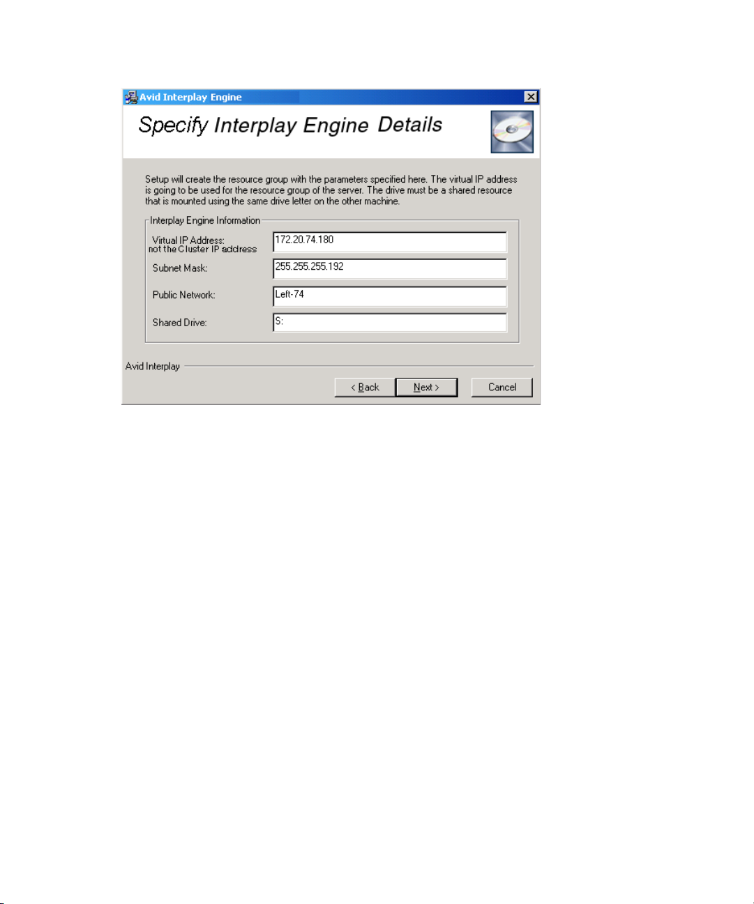
3 Installing the Interplay Engine for a Failover Cluster
To specify the Interplay Engine details:
86
c
1. Type the following values:
- Virtual IP address: This is the Interplay Engine service IP Address, not the Cluster
service IP address. For a list of example names, see “List of IP Addresses and
Network Names” on page 43.
- Subnet Mask: The subnet mask on the local network.
- Public Network: For a redundant-switch ISIS configuration or MediaNetwork
configuration, type Public. For a dual-connected ISIS configuration, type
Left-subnet. For a dual-connected configuration, you set the other public network
connection after the installation. See “Bringing the Disk Resource Online” on page
97. For MediaNetwork, type Public.
To check the public network connection on the first node, open the Network
Connections panel in the Windows Control Panel and look up the name there.
- Shared Drive: The letter of the shared drive that is used to store the database. Use S:
for the shared drive letter.
Make sure you type the correct information here, as this data cannot be changed
afterwards. Should you require any changes to the above values later, you will need to
uninstall the server on both nodes.
2. Click Next.
Page 87

The Specify Interplay Engine Name dialog box opens.
Specifying the Interplay Engine Service Name
In this dialog box, type the name of the Interplay Engine service.
Installing the Interplay Engine on the First Node
To specify the Interplay Engine name:
1. Specify the public names for the Avid Interplay Engine service by typing the following
values:
- The Network Name will be associated with the virtual IP Address that you entered
in the previous Interplay Engine Details dialog box. This is the Interplay Engine
service name (see “List of IP Addresses and Network Names” on page 43). It must
be a new, unused name, and must be registered in the DNS so that clients can find
the server without having to specify its address.
- The Server Name is used by clients to identify the server. If you only use Avid
Interplay Clients on Windows computers, you can use the Network Name as the
server name. If you use several platforms as client systems, such as Macintosh
®
Linux
you need to specify the static IP address that you entered for the resource
®
group in the previous dialog box. Macintosh systems are not always able to map
server names to IP addresses. If you type a static IP address, make sure this IP
address is not provided by a DHCP server.
2. Click Next.
and
87
Page 88

3 Installing the Interplay Engine for a Failover Cluster
The Specify Destination Location dialog box opens.
Specifying the Destination Location
In this dialog box specify the folder in which you want to install the Interplay Engine
program files.
88
c
To specify the destination location:
1. Avid recommends that you keep the default path C:\Program Files\Avid\Avid Interplay
Engine.
Under no circumstances attempt to install to a shared disk; independent installations
are required on both nodes. This is because local changes are also necessary on both
machines. Also, with independent installations you can use a rolling upgrade approach
later, upgrading each node individually without affecting the operation of the cluster.
2. Click Next.
The Specify Default Database Folder dialog box opens.
Page 89

Specifying the Default Database Folder
In this dialog box specify the folder where the database data is stored.
Installing the Interplay Engine on the First Node
To specify the default database folder:
1. Type S:\Workgroup_Databases. Make sure the path specifies the shared drive (S:).
This folder should reside on the shared drive that is owned by the resource group of the
server. Avid strongly recommends using the shared drive resource so that it can be
monitored and managed by the cluster service. The drive must be assigned to the
physical drive resource that is mounted under the same drive letter on the other
machine.
2. Click Next.
The Specify Share Name dialog box opens.
89
Page 90

3 Installing the Interplay Engine for a Failover Cluster
Specifying the Share Name
In this dialog box specify a share name to be used for the database folder.
90
To specify the share name:
1. Accept the default share name.
Avid recommends you use the default share name WG_Database$. This name is visible
on all client platforms, such as Windows 98, Windows ME, Windows NT Windows
2000 and Windows XP.The “$” at the end makes the share invisible if you browse
through the network with the Windows Explorer. For security reasons, Avid
recommends using a “$” at the end of the share name. If you use the default settings, the
directory S:\Workgroup_Databases is accessible as \\InterplayEngine\WG_Database$.
2. Click Next.
This step takes a few minutes. When finished the Specify Configuration Server dialog
box opens.
Page 91

Specifying the Configuration Server
Set for both nodes.
Use this option for
Interplay Archive
Engine
In this dialog box, indicate whether this server is to act as a Central Configuration Server.
Installing the Interplay Engine on the First Node
c
A Central Configuration Server (CCS) is an Avid Interplay Engine with a special module
that is used to store server and database-spanning information. For more information, see the
Avid Interplay Engine and Avid Interplay Archive Engine Administration Guide.
To specify the server to act as the CCS server:
1. Select either the server you are installing or a previously installed server to act as the
Central Configuration Server.
Typically you are working with only one server, so the appropriate choice is “This Avid
Interplay Engine,” which is the default.
If you need to specify a different server as the CCS (for example, if an Interplay Archive
Engine is being used as the CCS), select “Another Avid Interplay Engine.” You need to
type the name of the other server to be used as the CCS in the next dialog box.
Only use a CCS that is at least as high availability as this cluster installation, typically
another clustered installation.
91
Page 92

3 Installing the Interplay Engine for a Failover Cluster
If you specify the wrong CCS, you can change the setting later on the server machine in
the Windows Registry. See
2. Click Next.
The Specify Server User dialog box opens.
Specifying the Server User
In this dialog box, define the Cluster Service account (Server Execution User) used to run
the Avid Interplay Engine.
The Server Execution User is the Windows domain user that runs the Interplay Engine and
the cluster service. This account is automatically added to the Local Administrators group
on the server. This account must be the one that was used to set up the cluster service. See
“Before You Begin the Server Failover Installation” on page 42.
“Automatic Server Failover Tips and Rules” on page 107.
92
c
To specify the Server Execution User:
1. Type the Cluster Service Account user login information.
The installer cannot check the username or password you type in this dialog. Make
sure that the password is set correctly, or else you will need to uninstall the server and
repeat the entire installation procedure. Avid does not recommend changing the
Server Execution User in cluster mode afterwards, so choose carefully.
Page 93
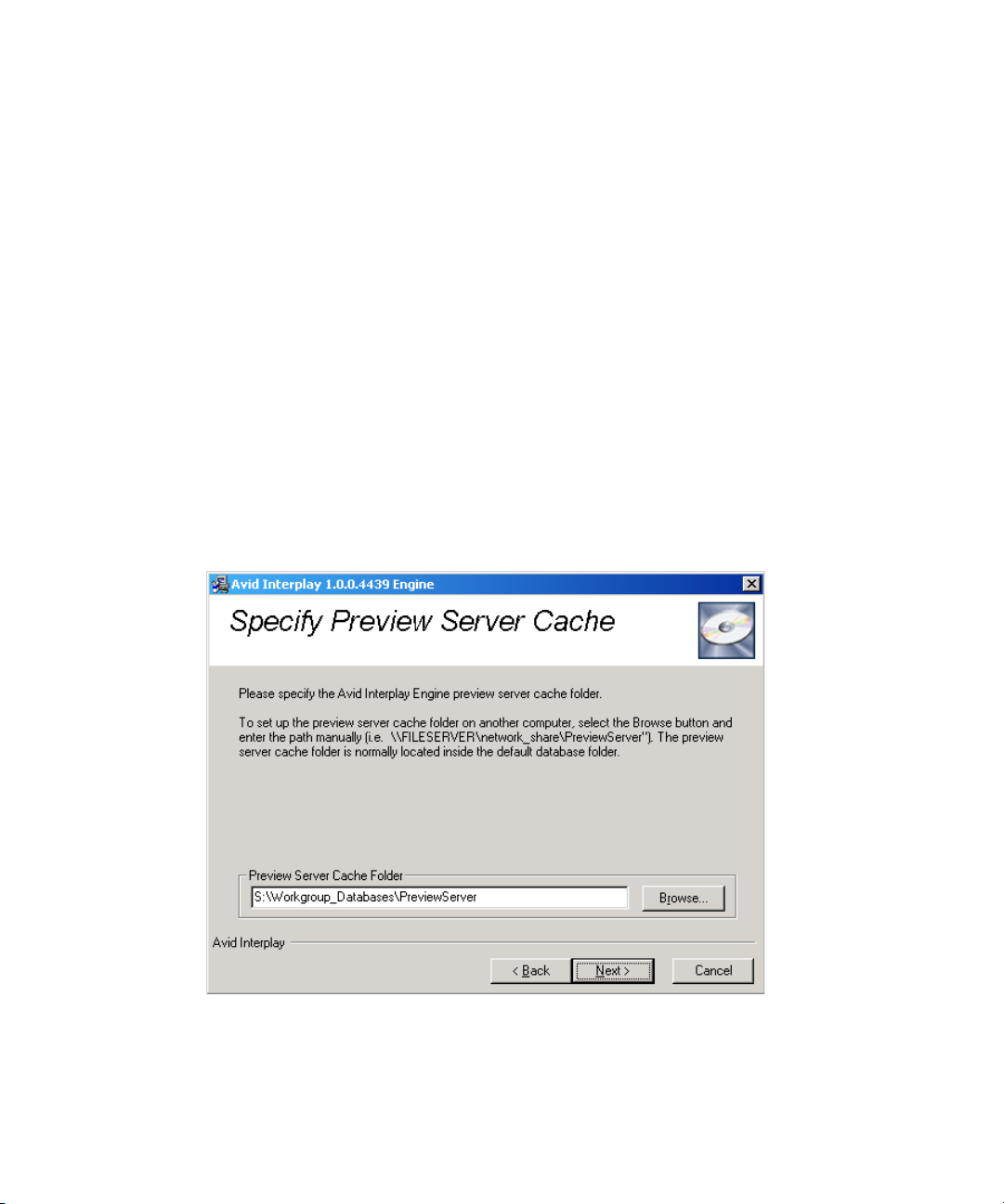
Installing the Interplay Engine on the First Node
c
Specifying the Server Cache
When typing the domain name do not use the full DNS name such as
mydomain.company.com, because the DCOM part of the server will be unable to start.
You should use the NetBIOS name, for example, mydomain.
2. Click Next.
The Specify Preview Server Cache dialog box opens.
If necessary, you can change the name of the Server Execution User after the installation.
For more information, see “Troubleshooting the Server Execution User Account” and
“Re-creating the Server Execution User” in the Avid Interplay Engine and Avid Interplay
Archive Engine Administration Guide and the Interplay ReadMe.
In this dialog box, specify the path for the cache folder.
For more information on the Preview Server cache and Preview Server configuration, see
n
“Avid Workgroup Preview Server Service” in the Avid Interplay Engine and Avid Interplay
Archive Engine Administration Guide.
To specify the server cache folder:
1. Type or browse to the path of the server cache folder. Typically, the default path is used.
2. Click Next.
93
Page 94

3 Installing the Interplay Engine for a Failover Cluster
The Enable Email Notification dialog box opens if you are installing the Avid Interplay
Engine for the first time.
Enabling Email Notifications
The first time you install the Avid Interplay Engine, the Enable Email Notification dialog
box opens. The email notification feature sends emails to your administrator when special
events, such as “Cluster Failure,” “Disk Full,” and “Out Of Memory” occur. Activate email
notification if you want to receive emails on special events, server or cluster failures.
94
To enable email notification:
1. (Option) Select Enable email notification on server events.
The Email Notification Details dialog box opens.
Page 95

Installing the Interplay Engine on the First Node
2. Type the administrator's email address and the email address of the server, which is the
sender.
If an event, such as “Resource Failure” or “Disk Full” occurs on the server machine, the
administrator receives an email from the sender's email account explaining the problem,
so that the administrator can react to the problem. You also need to type the static IP
address of your SMTP server. The notification feature needs the SMTP server in order
to send emails. If you do not know this IP, ask your administrator.
3. If you also want to inform Avid Support automatically using email if problems arise,
select “Send critical notifications also to Avid Support.”
4. Click Next.
The installer modifies the file Config.xml in the
Workgroup_Data\Server\Config\Config directory with your settings.
The Ready to Install dialog box opens.
95
Page 96

3 Installing the Interplay Engine for a Failover Cluster
Installing the Interplay Engine for a Custom Installation on the First Node
In this dialog box, begin the installation of the engine software.
96
To install the Interplay Engine software:
1. Click Next.
Use the Back button to review or change the data you have entered. You can also
terminate the installer using the Cancel button, because no changes have been done to
the system yet.
The first time you install the software, a dialog box opens and asks if you want to install
the Sentinel driver. This driver is used by the licensing system.
2. Click Continue.
The Installation Completed dialog box opens after the installation is completed.
Page 97

3. Do one of the following:
Installing the Interplay Engine on the First Node
t Click Finish.
t Analyze and resolve any issues or failures reported.
4. Click OK if prompted for a restart the system.
The installation procedure requires the machine to restart (up to twice). For this reason it
is very important that the other node is shut down, otherwise the current node loses
ownership of the Avid Workgroup resource group. This applies to the installation on the
first node only.
Subsequent installations should be run as described in “Updating a Clustered Installation
n
(Rolling Upgrade)” on page 104 or in the Avid Interplay ReadMe.
Bringing the Disk Resource Online
To bring the Disk Resource online:
1. After the installation is complete, start the Cluster Administrator tool by clicking Start
and selecting Programs > Administrative Tools > Cluster Administrator.
2. Open the Avid Workgroup Server resource group.
The list of resources should look similar to those in the following illustration.
97
Page 98

3 Installing the Interplay Engine for a Failover Cluster
Avid Workgroup Disk is online
98
The Avid Workgroup Disk resource should be online and all other resources offline.
3. Bring the disk resource online manually before continuing if necessary.
Avid does not recommend starting the server at this stage yet, since it is not installed on the
n
other node and a failover would be impossible.
4. (Avid Unity ISIS dual-connected configuration only) Add the IP address on the
second subnet for the Interplay Engine.
a. In the Cluster Administrator, right-click Avid Workgroup Server and select New >
Resource.
b. Complete the New Resource dialog box as follows:
- Name: Avid Workgroup Address 2
- Resource Type: IP Address
- Group: Avid Workgroup Server
c. Complete the Possible Owners dialog box as follows:
- Add the cluster server host names to the Possible owners lists. For example,
SECLUSTER1 and SECLUSTER2. See “List of IP Addresses and Network
Names” on page 43.
Page 99

Installing the Interplay Engine on the First Node
Avid Workgroup Address 2
d. Complete the Dependencies dialog box as follows:
- Leave the Resource dependencies list empty.
e. Complete TCP/IP Address Parameters dialog box as follows:
- Address: type the second Interplay Engine service Avid Unity ISIS IP address.
See “List of IP Addresses and Network Names” on page 43
- Subnet mask: displays subnet for the second subnet network
- Network: select a network connection: Right-subnet
- Select Enable NetBIOS for this address
f. Click Finish.
The following illustration shows the new entry.
g. Right-click Avid Workgroup Address 2 and select Properties.
h. Click the Advanced tab.
i. Deselect Affect the Group as shown in the following illustration.
99
Page 100

3 Installing the Interplay Engine for a Failover Cluster
Affect the group
option
Installing the Interplay Engine on the Second Node
100
c
j. Click OK.
5. When the installation is complete, leave this node running so that it maintains
ownership of the resource group and proceed to
Second Node” on page 100.
To install the Interplay Engine on the second node:
1. Leave the first machine running so that it maintains ownership of the resource group and
start the second node.
Do not attempt to move the resource group over to the second node, or similarly, do
not shut down the first node while the second is up, before the installation is completed
on the second node.
2. Perform the installation procedure for the second node as described in “Installing the
Interplay Engine on the First Node” on page 81. In contrast to the installation on the first
node, the installer automatically detects all settings previously entered on the first node.
The Attention dialog box opens.
“Installing the Interplay Engine on the
 Loading...