

Page 1

Interplay® Central Services
Version 1.8 Installation & Configuration Guide
ICS Version: 1.8 Document Version: 1.0.1
Important Infor mati on
Revision Histor y
Date Revised
Version
Changes Made
July 30, 2014
1.0.1
New section “Verifying the hosts file Contents”.
This document provides in str uctions to install and configure Avid Interplay Central Services (ICS)
version 1.8 for use with Interplay Central 1.8, Sphere (latest plug-in for Media Composer 6.5.x
and 7.0.x and correspondi ng NewsCutter versions), and Interplay MAM 4.3.x.
For the latest information on the Interplay Central Services, see the documentation available
from the Interplay Central Services page of the Avid Knowledge Base. Updates are occasionally
issued after initial release.
http://avid.force.com/pkb/articles/en_US/readme/Avid-Interplay-Central-Services-Version-1-8Documentation
Important: Search the Avid Knowledge Base ICS 1.8 web page for the most up-to-date
ICS 1.8 Installation and Co nfiguration Guide , which contains the latest information that
might have become available after this document was published.
Note: For information on upgrading to ICS 1.8 from an earlier release, see the ICS 1.8
Upgrading Guide, available from the Avid Knowledge Base
March 24, 2014 1.0 First publication
ICS 1.8 web page.
Updated “Adding Host Names and IP Addresses to the hosts File”.
Removed redundant editing of rc.local file from “Mounting the
GlusterFS Volumes in Linux”.
Page 2

ICS 1.8 Installation & Co nfiguration Guide
About ICS 1.8
Please see the Interplay Central Services 1.8 ReadMe and any ReadMe documents pertaining to
the solution(s) by which ICS is used.
2
Page 3

ICS 1.8 Installation & Co nfiguration Guide
Contents
Important Information ....................................................................................................................... 1
Revision History .................................................................................................................................. 1
ART I: INTRODUCTION & OVERVIEW ........................................................................................................... 10
P
Welcome .................................................................................................................................................. 11
About this Guide ...................................................................................................................................... 12
Licensing and Additional Installation Information ................................................................................... 12
Front End License Configuration .......................................................................................................... 12
Delivery of Licenses on Back-End Systems ........................................................................................... 13
Installing the iPhone and iPad Apps ..................................................................................................... 13
Intended Audiences and Prere q uisites .................................................................................................... 13
Basic Installation Skills .......................................................................................................................... 14
Clustering Skills ..................................................................................................................................... 14
Interplay MAM Skills ............................................................................................................................ 14
Deployment Options ................................................................................................................................ 15
Interplay Central – iNEWS Only ............................................................................................................ 15
Interplay Central – Interplay Production Only ..................................................................................... 16
Interplay Central – iNEWS and Interplay Production ........................................................................... 17
Interplay Sphere Only ........................................................................................................................... 18
Both Interplay Central and Interplay Sphere (Shared ICS) ................................................................... 19
Interplay MAM ..................................................................................................................................... 20
Port Bonding in Interplay MAM ........................................................................................................ 21
Port Requirements ................................................................................................................................... 21
Caching in ICS ........................................................................................................................................... 22
The Dedicated Caching Volume ........................................................................................................... 22
Caching for Interplay MAM .................................................................................................................. 23
Caching for iOS Devices in Interplay Central ........................................................................................ 23
Caching for Sphere ............................................................................................................................... 23
Working with Linux .................................................................................................................................. 24
Installing Linux ...................................................................................................................................... 24
Linux Concepts ..................................................................................................................................... 24
Key Linux Directories ............................................................................................................................ 25
Linux Command Line ............................................................................................................................ 25
3
Page 4

ICS 1.8 Installation & Co nfiguration Guide
Linux Text Editor (vi) ............................................................................................................................. 27
Linux Usage Tips ................................................................................................................................... 28
Volumes in Linux .................................................................................................................................. 29
Clock Synchronization i n Linux ............................................................................................................. 29
Time Zones in RHEL .............................................................................................................................. 30
RAIDs in ICS .............................................................................................................................................. 30
Introduction to Clusteri n g ........................................................................................................................ 31
Single Server Deployment .................................................................................................................... 32
Cluster Deployment .............................................................................................................................. 33
Multicast vs Unicast ............................................................................................................................. 33
Working with Gluster ........................................................................................................................... 34
ART II: INSTALLING & CONFIGURING ........................................................................................................... 35
P
Installation Workflow............................................................................................................................... 36
Before You Begin ...................................................................................................................................... 39
Make Sure the Host Solutions Are I nstalled and Running ................................................................... 39
Make Sure You Have the Following Items ............................................................................................ 39
Make Sure You Can Answer the Following Questions ......................................................................... 40
Make Sure You Have All the Information You Need ............................................................................ 42
Make Sure You Change the Default Passwords ................................................................................... 42
Obtaining the Software ............................................................................................................................ 43
Obtaining the ICS Installation Package ................................................................................................. 43
Obtaining Red Hat Enterprise Linux ..................................................................................................... 44
Obtaining Gluster ................................................................................................................................. 45
Obtaining Additional Packages ............................................................................................................. 45
Preparing the ICS Installation USB Key .................................................................................................... 46
Transferring ICS and Linux to the USB Key ........................................................................................... 46
Copying Gluster to the U SB Key ........................................................................................................... 48
Installing the Network Interface Cards .................................................................................................... 49
Connecting to ISIS Proxy Storage ......................................................................................................... 49
Connecting to non-ISIS Proxy Storage .................................................................................................. 50
Setting the System Clock and Disabling HP Power Saving Mode ............................................................ 51
Setting Up the RAID Level 1 Mirrored System Drives .............................................................................. 52
Setting Up the RAID Level 5 Cache Drives ............................................................................................... 54
4
Page 5

ICS 1.8 Installation & Co nfiguration Guide
Installing RHEL and the ICS Software ....................................................................................................... 56
Booting RHEL for the First Time ............................................................................................................... 58
Booting from the System Drive ............................................................................................................ 59
Changing the root Password ................................................................................................................ 60
Verifying the Date and Time................................................................................................................. 60
Setting the Time Zone .......................................................................................................................... 61
Editing the Network Connections ............................................................................................................ 62
Identifying NIC Interfaces by Sight ....................................................................................................... 62
Verifying the NIC Interface Name ........................................................................................................ 63
Swapping NIC Interface Names ............................................................................................................ 64
Removing the MAC Address Hardware References ............................................................................. 65
Configuring the Hostname and St a tic Network Route ......................................................................... 66
Verifying the hosts file Contents .......................................................................................................... 68
Verifying Network and DNS Connectivity ............................................................................................. 69
Synching the System Clock ....................................................................................................................... 70
Creating the File Cache on the RAID ........................................................................................................ 72
Partitioning the RAID ............................................................................................................................ 72
Creating the Logical Volume and Mounting the Cache ........................................................................ 73
Installing the Interplay Central Distribution Service ................................................................................ 76
Determining Where to Install ICDS ...................................................................................................... 76
Before You Begin .................................................................................................................................. 77
Configuring ICS for Interplay MAM .......................................................................................................... 78
Configuring ICS for Interplay Central and/or Interplay Sphere ............................................................... 80
Configuring Workflow .......................................................................................................................... 80
Before You Begin .................................................................................................................................. 82
Configuring the Interplay Central UI .................................................................................................... 83
Logging into Interplay Central .............................................................................................................. 84
Changing the Administrator Password ................................................................................................. 88
Configuring iNEWS Settings .................................................................................................................. 88
Configuring Interplay Production Settings ........................................................................................... 89
Configuring ICPS for Interplay .............................................................................................................. 90
Configuring the ICPS Player .................................................................................................................. 92
Configuring the ICPS Player for Interplay Sphere ................................................................................. 92
5
Page 6

ICS 1.8 Installation & Co nfiguration Guide
Configuring the ISIS Connecti on(s) ....................................................................................................... 93
Mounting the ISIS System(s) ................................................................................................................ 94
Verifying the ISIS Mount ....................................................................................................................... 95
Verifying Video Playback ...................................................................................................................... 96
Configuring Wi-Fi Only Encoding for Facility-Based iOS Devices ......................................................... 97
ART III: CLUSTERING .................................................................................................................................. 98
P
Setting up the Server Cluster ................................................................................................................... 99
Clustering Workflow .............................................................................................................................. 101
Before You Begin ................................................................................................................................ 102
Configuring the Hosts File and Name Services File ................................................................................ 103
Adding Host Names and IP Addresses to the hosts File ..................................................................... 103
Optimizing the Lookup Servic e Order: Editing the Name Service Switch File .................................... 104
Setting Up DRBD .................................................................................................................................... 105
Starting the Cluster Services .................................................................................................................. 108
Joining the Cluster .................................................................................................................................. 111
Replicating the Cluster File Caches ........................................................................................................ 112
Before You Begin ................................................................................................................................ 112
Mounting the USB Key ....................................................................................................................... 113
Installing Gluster................................................................................................................................. 114
Unmounting and Removing the USB Key ........................................................................................... 115
Creating the Trusted Storage Pool ..................................................................................................... 115
Configuring the GlusterFS Volumes ................................................................................................... 117
Making Cache Directories and Changing Ownership ......................................................................... 119
Mounting the GlusterFS Volumes in Linux ......................................................................................... 121
Testing the Cache ............................................................................................................................... 122
Ensuring Gluster is On at Boot ........................................................................................................... 122
Reconfiguring the ICPS Player for Interplay Central in a Cluster........................................................ 123
ART IV: POST-INSTALLATION .................................................................................................................... 124
P
Post-Installation Steps ........................................................................................................................... 125
Determining the Installed ICS Version................................................................................................ 125
Verifying Cache Directory Permissions .............................................................................................. 125
Securing the System ........................................................................................................................... 126
Enabling and Securing the Player Demonstration Web Page ............................................................ 126
6
Page 7

ICS 1.8 Installation & Co nfiguration Guide
Backing up the ICS System Settings and the ICS Database ................................................................ 127
Monitoring Services and Resources ................................................................................................... 130
Monitoring the AAF Generator Service .............................................................................................. 133
Monitoring ICS High-Availability......................................................................................................... 135
Monitoring Load Balancing ................................................................................................................ 136
Observing Failover in the Cluster ....................................................................................................... 137
Testing the Cluster Email Service ....................................................................................................... 140
Changing the Cluster Administrator Email Address ........................................................................... 141
Reconfiguring Interplay Central Settings in a Cluster......................................................................... 142
Taking a Cluster Node Off-Line Temporarily ...................................................................................... 142
Permanently Removing a Node from a Cluster .................................................................................. 142
Adding a New Node to a Cluster ........................................................................................................ 142
Retrieving ICS Logs ............................................................................................................................. 145
Log Cycling .......................................................................................................................................... 146
Using SNMP Monitoring on the ICPS Server ...................................................................................... 146
Migrating the ICP Database from Windows to Linux ......................................................................... 146
Backing up and Restoring the ICS Data base ....................................................................................... 146
Appendix A: Installing IC S on Non-HP Hardware ................................................................................... 148
Non-HP Installation Notes .................................................................................................................. 148
Appendix B: Table of Deployment Options and Requirements ............................................................. 150
Appendix C: Configuring Port Bonding for Interplay MAM (Optional) .................................................. 152
Verifying the Ethernet Ports ............................................................................................................... 152
Configuring the Port Bonding ............................................................................................................. 153
Appendix D: Handling SSL Certificates ................................................................................................... 155
Built-In Browser Functionality ........................................................................................................ 155
SAN Certificates .............................................................................................................................. 156
Understanding the “Certificate Not Trusted” Warning ...................................................................... 156
Eliminating the Certificate not Trusted and Name Mismatch Warnings ........................................... 157
Generating a Self-Signed Certificate for a Single Server .................................................................... 158
Generating a Self-Signed Certificate for a Server Cluster .................................................................. 160
Before You Begin ............................................................................................................................ 161
Obtaining a Trusted CA-signed Certificate ......................................................................................... 168
Adding a CA-Signed Certificate to a Single Server .............................................................................. 171
7
Page 8

ICS 1.8 Installation & Co nfiguration Guide
Adding a CA-Signed Certificate to a Server Cluster ............................................................................ 176
Configuring Google Chrome (Windows) ............................................................................................ 178
Configuring Internet Explorer (Windows) .......................................................................................... 182
Configuring Safari (Mac OS) ............................................................................................................... 186
Launching the Windows Import SSL Certificate Directly .................................................................... 187
The Interplay Central Application Properties File .............................................................................. 188
Appendix E: Migrating the UMS Database with the User Management Utilities Tool .......................... 189
Appendix F: Installing t he Chrome Extension for Interplay Central MOS Plug-Ins ................................ 192
Setting Up Your Browser .................................................................................................................... 192
Enabling MOS ..................................................................................................................................... 192
Installing Plug-Ins ............................................................................................................................... 192
Uninstalling the Chrome Extension .................................................................................................... 193
Appendix G: Enabling Interplay Central MOS Plug-Ins in IE9................................................................. 194
Sample ActiveX Object in the Preferences File .................................................................................. 195
Appendix H: Unicast Support in Clustering ............................................................................................ 197
Appendix I: Installing t h e Inter play Production License for Interplay Central ....................................... 200
Appendix J: Configuring iNEWS f or Integration with Interplay Central ................................................. 201
Verifying Interplay Central Licenses on iNEWS .................................................................................. 201
Editing SYSTEM.CLIENT.VERSIONS ..................................................................................................... 202
Editing SYSTEM.CLIENT.WINDOWS .................................................................................................... 203
Appendix K: Installing and Configuring the Avid Central Mobile Application for the iPad or iPhone ... 205
Before You Begin ................................................................................................................................ 205
iNEWS Configuration for iPad and iPhone Integration ...................................................................... 205
Editing SYSTEM.CLIENT.VERSIONS ..................................................................................................... 206
Adding iPad and iPhone Devices to the iNEWS Configuration File .................................................... 207
Installing Avid Central on the iPad or iPhone ..................................................................................... 208
Appendix L: Installation Pre-Flight Checklist .......................................................................................... 210
Default Password Information ........................................................................................................... 210
Contact Information ........................................................................................................................... 210
Hardware ............................................................................................................................................ 211
Software ............................................................................................................................................. 211
Network Settings ................................................................................................................................ 211
NTP Time Server ................................................................................................................................. 212
8
Page 9

ICS 1.8 Installation & Co nfiguration Guide
ICS Server Information ....................................................................................................................... 212
Cluster Information ............................................................................................................................ 213
iNEWS Information ............................................................................................................................. 214
Interplay Central and Interplay Sphere Information .......................................................................... 214
Interplay Production Information ...................................................................................................... 215
ISIS Information .................................................................................................................................. 216
Interplay MAM Information ............................................................................................................... 217
Copyright and Disclaimer ....................................................................................................................... 218
9
Page 10

ICS 1.8 Installation & Co nfiguration Guide
PART I: INTRODUCTION & OVERVIEW
10
Page 11

ICS 1.8 Installation & Co nfiguration Guide
Welcome
Welcome to the ICS Installation and Co nfi guration Guide . This document will guide you through
the installation and set up of the Interplay Central Services (ICS) software components. It
provides step by step instructions to visually verify the hardware setup, install Linux and the ICS
software, and configure the software systems that will make use of ICS. It also provides detailed
steps for optional activities, for example: setting up a cluster of ICS servers, or configuring for an
iPad-only deployment.
Note: Beginning with version 1.6, the term “Interplay Central Services” replaces
“Interplay Common Services.” In addition, t he term “I nterplay Central Playback Service”
replaces “Interplay Common Playback Service.”
ICS is a set of software services running under t h e Linux operating system. ICS serves layouts for
applications, provides user authentication, manages system configuration settings, and provides
proxy-based playback of video assets over the network to web-based and mobile clients.
ICS supports several different Avid Integrated Media Enterprise (IME) solutions, including
Interplay Central, and Interplay Sphere, and Interplay MAM. ICS installs on its own set of
servers, distinct from the IME solution it is supporting. Multiple ICS servers can be clustered
together to obtain one or more of high-availability, load balancing and scalability.
Note: Refer to the “How to Buy Hardware for Interplay Central Services” guide for
detailed information on hardware specifications and deployment options. The guide is
available on the Avid Knowledge Base
The installation and configuration steps vary depending on the deployment model, target
hardware, and optional steps. For example, installations on qualified HP servers can use an
express process involving a USB key and the supplied Red Hat Enterprise Linux kickstart (ks.cfg)
file. Kickstart files are commonly used in Linux installs to automatically answer questions for
hardware known in advance. On non-HP servers you must install Red Hat Enterprise Linux
manually.
Note: All decisions pertaining to hardware, deplo yment mode l, optional activities (such
as setting up a cluster), network connections (GigE vs 10GigE), must be made before
beginning the installation. If these decisions have not been taken, or, to verify a non-HP
server, please consult an Avid representative.
Red Hat Enterprise Linux — sometimes just called Red H at, but ref err ed to in this guide as RHEL
— is a commercially supported, open source version of the popular Linux operating system. No
matter what the deployment model and target hardware, the installation of RHEL is mandatory.
Note: ICS requires RHEL 6.3. Do not i nstal l any OS updat es, patches. Do not upgrade to
RHEL 6.4 or higher. Do not run the Linux yum update command.
ICS 1.8 web page.
For more information on Red Hat see “Wor king with Linux ” on page 24
support options are covered in the “How to Buy Hardware for Interplay Central Services” guide,
available on the
11
Avid Knowledge Base ICS 1.8 web page.
. RHEL licensing and
Page 12

ICS 1.8 Installation & Co nfiguration Guide
About this Guide
Licensing and Additional Installation Information
Front End License Configuration
Note: Clock setting and synchronization play an important role in some ICS deployments.
For a discussion of the issues associated with clock synchronization and using a time
server to set the system clock, see “Clock Synchronization in Linux” on page 29
.
This guide provides all the inst ructions you need to set up ICS 1.8. The installation and
configuration is complex and can be difficult, particularly if you are unfamiliar with Linux.
The following tips will ensure a smooth installation:
• Read the whole guide, thoroughly and all the way through, before beginning the
installation process.
• Gather all the information required to perform the install before you start. Waiting until
the information is called for by an installation step will result in considerable delays.
• For a list of required information, see “Appendix L: Installation Pre-Flight Checklist
page 210.
• Complete all the relevant sections in the pre-flight checklist for your deployment.
Licenses must be installed on an iNEWS server, an Interplay Production server, or both. No
licenses are installed on the Interplay Central Services server.
For Interplay Production, the license types are J (Interplay Production Base license) an d G
(Advance license).
• Base license: Ca n connect to only one system type: iNEWS or Interpl ay Production.
Access is limited to specific panes.
• Advance licens e: Can connect to both system types: iNEWS and Interplay Production,
with access to all panes.
Note: Please refer to the “Interplay Central Administration Guide” for licensing details,
such as the panes and features made available by each license t y pe. The guide is
available with other Interplay Central v1.8 documentation on the Avid Knowledge Base:
http://avid.force.com/pkb/articles/en_US/readme/Avid-Interplay-Central-Version-1-81-8-Documentation
” on
You specify the type of license for each Interplay Central role in the Details tab of the Users
layout. For more information, see "Interplay Central Client Licensing" in the Avid Interplay
Central Administration Guide.
12
Page 13

ICS 1.8 Installation & Co nfiguration Guide
Delivery of Licenses on Back-End Systems
Installing the iPhone and iPad Apps
Intended Audiences and Prerequisites
An iNEWS client license or an Interplay Central mobile license for a specified number of clients is
sent to the customer through email along with specific installation instructions. However, to
ensure proper licensed integration between Interplay Central and iNEWS, additional
modification to system files in the iNEWS database is also required.
For more information see “
Central” on page 201.
An Interplay Production license for a specified number of clients is supplied to the customer on
a USB flash drive as a file with the extension nxn.
For more information, see “
Central” on page 200.
Appendix J: Conf i g ur ing iNEWS for Inte gration with Inte r p l ay
Appendix I: Installing the Interplay Production License for Interplay
The Avid Central mobile application is a native user interface designed to run on the Apple iPad
touch-screen tablet and the Appl e iPhone touch-screen phone, and enable direct, secure access
to your station’s iNEWS newsroom computer system.
For installation information, see “
Mobile Application for the iPad or iPhone” on page 205.
Appendix K: Installing and Configuring the Avid Central
This guide is aimed at the person responsible for performing a fresh install of ICS, or upgrading
or maintaining an existing ICS installation. It can also be used by someone creating a cluster of
ICS nodes out of a non-clustered setup. In particular, the following audiences have be en
identified:
• Avid Professional Services: Avid personnel whose responsibilities include installing and
upgrading the ICS system, on-site at a customer’ facility.
• Avid Channel Partners and Resellers: Selected organizations qualified by Avid to educate,
market, sell, install, integrate and provide support for the Avid product line, including ICS.
• In-House Installers: Clients with a sophisticated in-house IT department that has expertise
in systems integration and Linux (including networking, port-bonding, etc.). This kind of
person might be called on to add a new server to an already established cluster of ICS
servers, for example.
13
Page 14

ICS 1.8 Installation & Co nfiguration Guide
Basic Installation Skills
Clustering Skills
Interplay MAM Skills
The following skills are needed to perform the basic installation:
• Windows: Format a USB key, unzip files, etc.
• Server: Access to the physical server, booting/rebooting, interrupting startup screens to
enter BIOS and other utilities, navigating and altering BIOS, setting up RAIDs.
• Network Interface Cards (NI Cs ): Identify a NIC, knowledge of which NIC interface is
being used.
• Linux (install): Previous experience installing Linux is preferred but not essential,
knowledge of manually installing RPM files will be helpful.
• Linux (general): Work with Linux directories (cd, mkdir, ls), create volumes,
mount/unmount directori es, volumes and devices (e.g. USB key) , verify the status of a
Linux service.
• Linux (file editing): Use the Linux text editor (vi) to open/create files, add/delete text,
save/close files, etc.
• Networking: An understanding of network topologies and Ethernet protocols (TCP/IP),
using ping command, verify/change a NIC card Ethernet interface (i.e. eth0).
• System Clocks: Setting the system clock in BIOS and in Linux. For a discussion of system
clock options, see “Clock Synchronizat i on” on page 29
.
The following skills are desirable for setting up a cluster of ICS nodes:
• Gluster: Familiarity with Gluster, as it is used to create a shared pool of storage,
including starting/stopping Gluster services, creating shared storage pools, creating
GlusterFS volumes, etc.
• Networking: A basic understanding of unicast or multicast and IP ne tworking. An
advanced understanding of networking in Linux would be helpful, but is not essential,
since all instructions are provided.
The following skills are desirable or setting up ICS for Interplay MAM (port bonding optional):
• Port Bonding (general): Knowledge of theory and practice of port bonding (also called
link aggregation).
• Port Bonding (Linux): Understanding contents and purpose of Linux network-scripts
directory, editing interface configuration (ifcfg-ethN) files, restarting network services.
Note: Port bonding is an option that is exclusive to Int erpl ay MAM installations. Do not
perform port bonding when performing any other kind of install.
• Interplay MAM configuration: Ability to work as administrator in Interplay MAM.
14
Page 15
ICS 1.8 Installation & Co nfiguration Guide
Deployment Options
Interplay Central – iNEWS Only
ICS is a collection of software services designed to support a number of Avid enterprise solutions
and deployment options. S ince each deployment scenario has different hardware and software
configuration requirements (and playback characteristics), it will be helpful to have a high-level
overview of the deployment of interest before proceeding.
As noted, the installation follows one of these basic deployment models:
• ICS for Interplay Central
o iNEWS only
o Interplay Production only
o iNEWS and Interplay Production
• ICS for Inter play Sphere
• ICS for Interplay Central and Interplay Sphere (Shared ICS)
• ICS for Interplay MAM
This section provides an overview of each of these deploymen ts.
For a detailed technical summary of deployment options, see “
Deployment Opt ions and Requirements” on page 150.
Appendix B: Table of
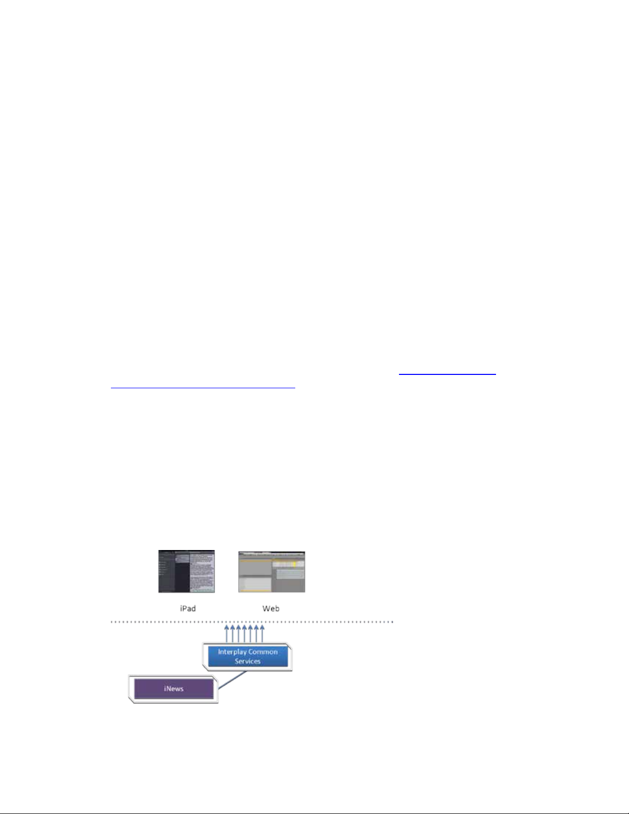
One of the most straightforward deployments is ICS for Interplay Central in an iNEWS-only
environment; that is, with connections to iNEWS but no connection to Interplay Production. In
this deployment ICS provides the ability to browse and edit iNEWS content (queues, stories)
from a remote web client. The ability to browse, play and edit associated video requires
Interplay Production a n d is not p ro vided by the iNEWS-only deployment.
Interplay Central for iNEWS:
15
Page 16
ICS 1.8 Installation & Co nfiguration Guide
Interplay Central – Interplay Production Only
The iNEWS-only deployment typically requires a RAID 1 (mirrored RAID) for the Linux operating
system. Since ICS is not providing playback of any video assets, there is no need for caching, so
the media cache volume referred to in this guide is not required. Typically, a single ICS server is
sufficient. Two ICS servers configured as a cluster provide high-availability.
Note: The iNEWS-only deployment can be
on smaller, less expensive server hardware.
Refer to the “How to Buy Hardware for Interplay Central Services” gui de f o r detailed
information on hardware specifications and deployment opt i ons. The guide is available
on the Avid Knowledge Base
ICS 1.8 web page.
Deployment Summary:
• Browse and edit iNEWS content
• RAID 1 required
• Media cache volume not required
• Clustering yields high-availability
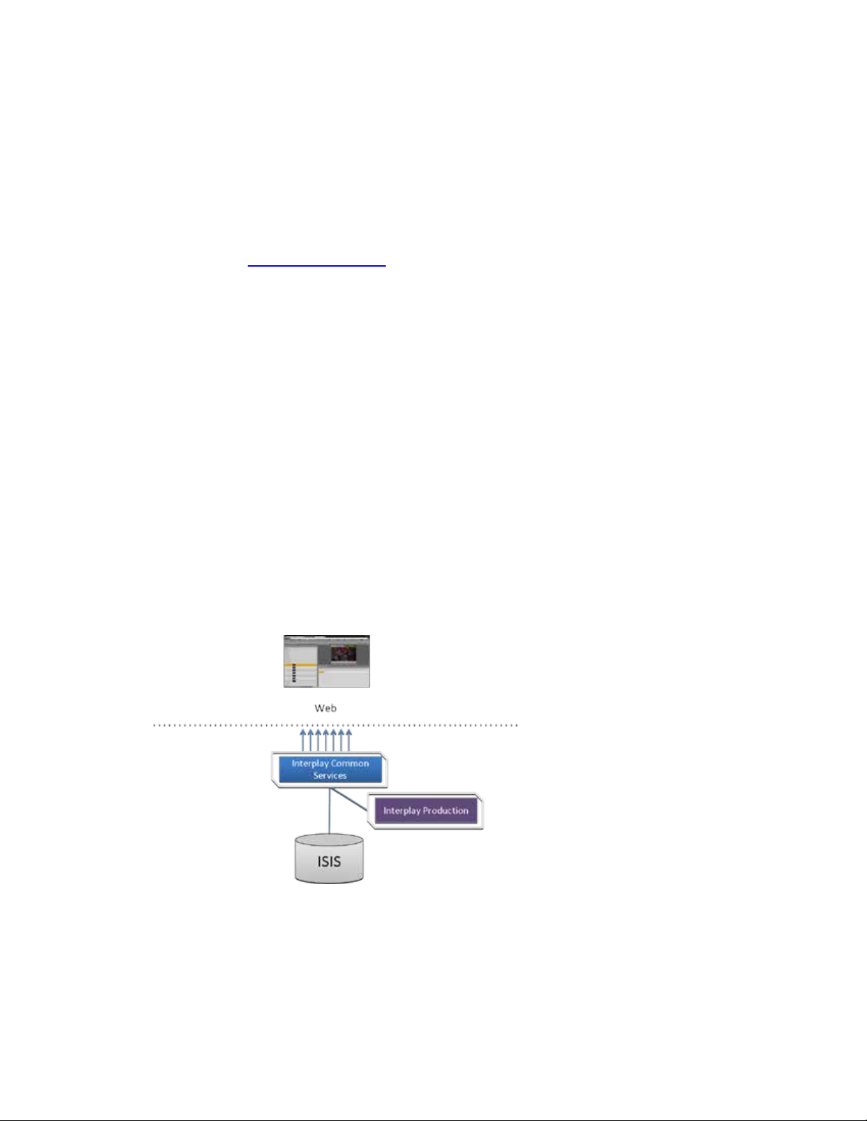
ICS for Interplay Central with Interplay Production has connections to Interplay Production only.
In this deployment ICS serves layouts for applications, provides user authentication, manages
system configuration settings, and provides proxy-based playback o f video assets over the
network to web-based and mobile clients. ICS decodes the source format and streams images
and sound to the remote web-based Interp
Interplay Central for Interplay Production:
l
ay Centr al client.
This deployment typically requires two HDs configured as a RAID 1 (mirrored RAID) for the Linux
operating system. No iOS devices implies no special caching requirements; however, Multicam
requires a media drive. You can configure two or more ICS servers as a cluster to obtain highavailability and load balancing.
16
Page 17
ICS 1.8 Installation & Co nfiguration Guide
Interplay Central – iNEWS and Interplay Production
Deployment Summary:
• Browse and play video assets
• RAID 1 required
• Media cache volume required
o RAID 5, or
o RAID 1, or
o Single HD
• Clustering yields high-availability and load-balancing
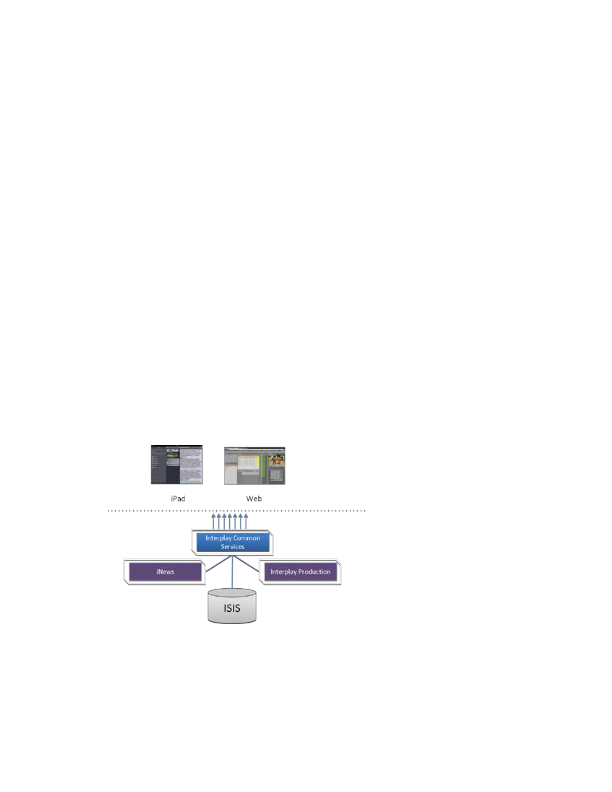
ICS for Interplay Central with iNEWS and Interplay Production has both iNEWS connectivity and
Interplay Production connectivity. Similarly to the iNEWS-only deployment, this provides the
ability to browse and edit iNEWS content (queues, stories) from a remote web client. Interplay
Production connectivity provides the ability to browse, play and edit associated video.
In this deployment ICS serves layouts for applications, provides user authentication, manages
system configuration settings, and provides proxy-based playback of video assets over the
network to web-based and mobile clients. ICS decodes ISIS source formats and streams images
and sound to the remote web-based Interplay Central client.
Interplay Central with iNEWS and Interplay Pr oduction:
This deployment typically requires two HDs configured as a RAID 1 (mirrored RAID) for the Linux
operating system. In a configuration where the iOS application is used, the ICS server should also
have a media cache volume. Multicam also requires a media cache volume. You can configure
two or more ICS servers as a cluster to obtain high-availability and load balancing.
17
Page 18

ICS 1.8 Installation & Co nfiguration Guide
Interplay Sphere Only
Deployment Summary:
• Browse and edit iNEWS content
• Browse and play the associated video assets
• RAID 1 required
• Media cache volume required
o RAID 5, or
o RAID 1, or
o Single HD
• Clustering yields high-availability and load-balancing
ICS for Interplay Sphere provides playback of different format video assets registered by
Interplay Production and residing on an ISIS
images and sound to the remote Interp
.
ICS decodes the source format and streams
l
ay Sphere enabled Media Composer or NewsCutter.
Interplay Sphere:
This deployment ty pically req uires two HDs configured as a RAID 1 (mirrored RAID) for the
Linux operating system. A media cache is also required. In its most basic form, the Interplay
Sphere deploym e nt is a si ngle ICS serve r. You can configure two or more ICS servers as a cluster
to obtain high-availability and load balancing.
Deployment Summary:
• Browse and play th e v ideo assets for Sphere enabled Media Composer and/or
NewsCutter
• RAID 1 required
• Media cache volume required
18
Page 19
ICS 1.8 Installation & Co nfiguration Guide
Both Interplay Central and Interplay Sphere (Shared ICS)
o RAID 5, or
o RAID 1, or
o Single HD
• Clustering yields high-availability and load-balancing
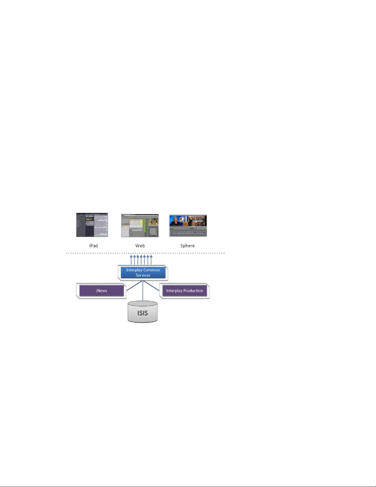
Interplay Central and Interplay Sphere can easily share the same ICS server(s). In this
deployment, ICS serves layouts for applications, provides user authentication, and manages
system configuration settings. ICS also provides proxy-base playback over the network of
different format v
decodes the source format and streams images and sound to the remote web-based Interplay
Central and/or Interp
This is the most sophisticated deployment model, since other elements can also be present,
such as iNEWS with corresponding iOS device applications.
Interplay Central and Interplay Sphere (Shared ICS):
i
deo assets registered by Interplay Production and residing on an ISIS. ICS
l
ay Sphere clients
.
This deployment typically requires a RAID 1 (mirrored RAID) for the Linux operating system. In a
configuration with iO S devices (as with iNEWS), the ICS server should also have a media cache
volume. If iOS devices are not deployed, it has no media cache volume requirements; however,
multicam requires a media cache volume. You can configure two or more ICS servers as a cluster
to obtain high-availability and load balancing.
Deployment Summary:
• Browse and play video assets
• Browse and play video assets
for Sphere enabled Media Composer and/or NewsCutter
• RAID 1 required
19
Page 20
ICS 1.8 Installation & Co nfiguration Guide
Interplay MAM
• Media cache volume required
o RAID 5, or
o RAID 1, or
o Single HD
• Clustering yields high-availability and load-balancing
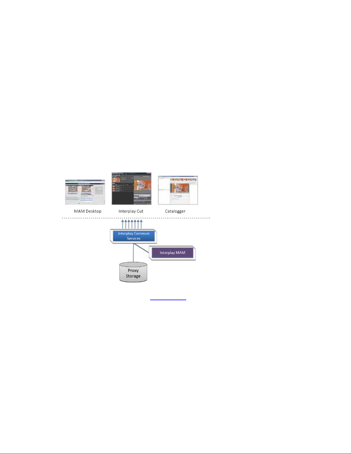
In an Interplay MAM deployment, ICS provides playback of video assets registered as a browse
proxies by Interplay MAM. The registered browse proxies can reside on standard filesystem
storage, or proprietary storage that provides a standard system gateway. The Interplay MAM
deployment presents two main options – setting up a media cache volume, and port bonding to
improve throughput.
Interplay MAM:
This deployment typically requires a RAID 1 (mirrored RAID) for the Linux operating system.
Under some circumstances – see “Caching in IC S ” on page 22
– the ICS server should also have a
media cache volume. You can configure two or more ICS servers as a cluster to obtain highavailability and load balancing.
Deployment Summary:
• Browse and play video assets
• RAID 1 required
• Media cache volume might be required
o RAID 5, or
o RAID 1, or
o Single HD
• Clustering yields high-availability and load-balancing
20
Page 21

ICS 1.8 Installation & Co nfiguration Guide
Port Bonding in In terp lay MAM
Port Requirements
Interplay Central
80
TCP inbound
Interplay Central Playback Service (ICPS)
443
Secure TCP
IPC HTTPS calls
843
TCP Inbound
Serving Flash Player socket policy files
5000
TCP Inbound
Playback service (loading assets, serving
Interplay Central
80
TCP Inbound
ICPS HTTP calls
443
Secure TCP
ICPS HTTPS calls
Port bonding (also called link aggregation) is an OS-level technique for combining multiple
Ethernet ports into a group, making them appear and behave as a single port. Ethernet ports
correspond to the physical con nectors in a NIC card where network cables are plugged in.
Bonded ports retain their individual cable connections to the network router or switch.
However, they are seen by the network as a single port.
Port bonding must be configured in “round-robin” mode. In this mode, Ethernet packets are
automatically sent, in tu r n , to each of the bonded ports, reducing bottlenecks and increasing the
available bandwidth. For example, bonding two ports together in round-robin increases
bandwidth by approximately 50% (some efficiency is lost due to overhead).
In MAM deployments of ICS, port bonding improves playback performance when multiple
clients are making requests of the ICS server simultaneously. With port bonding, more
concurrent playback requests can be sustained by a single server, especially for file-based
playback. File-based playback is a playback method for which a single port-bonded ICS server
can support thousands of requests.
For instructions on port bonding see “
(Optional)“ on page 152.
The following table lists the ICS port requirements for the client-side applications (the browserbased Interplay Central application and mobile applications). Ports 80 and 443 are required for
the HTTP(S) traffic. In addition, the Adobe Flash Player (running inside the browser) requires
ports 843 and 5000.
For more information see the ICS Security Archi tect ure and Analysis document.
Component Port Protocol and
Web application
Appendix C: Configuring Port Bonding for Interplay MAM
Usage
Direction
HTTP calls
Inbound
mobile applications
21
JPEG images, and audio, etc.). Ou tput flow
to client serving inbound request.
Inbound
Page 22

ICS 1.8 Installation & Co nfiguration Guide
Interplay Central
80, 443
ICPS
843 (Flash), 80, 5000, 26000
ICS
8000 (optional Admin UI), 8183 (bus cluster info)
ISIS
5000 – 5399 (UPD and TCP)
RabbitMQ
5672 (AMQP), 15672 (Management UI/API)
MongoDB
27017
PostgreSQL
53087
System
22, ICMP, 111, 2400 7, 24008, 24009-(24009 + number of bricks
Caching in ICS
The Dedicated Caching Volume
The following table lists the server-side port requirements. For more information see the ICS
Security Architecture and Analysis document.
Service Name Port
across all volumes for gluster). If you will be using NFS, open
additional ports 38465-(38465 + number of Gluster servers). Some
MAM configuration might require additional NFS ports (111, 2049
tcp & udp) or CIFS (137,138 udp and 137 ,139 tcp). Other filesystems
will have to be checked individually (Isilon, Harmonic Omneon,
etc.).
In its work to provide proxy-based playback of video assets over a network, ICS generates
temporary files in certain workflows. For example, ICS deployed for Interplay MAM typically
generates a multitude of temporary files as it converts proxies from their native MAM formats
into formats compatible with the player. The ICS multicam feature introduced in ICS 1.5
produces numerous temporary files. By default, ICS caches temporary files on the system drive.
Better performance is achieved by allocating a dedicated media cache volume (separate from
the system drive) for the temporary files. In a cluster setup, an open-source software solution
called Gluster is also used.
Note: All
for media caching. Gluster is also required, for file replication between clustered caches.
Note: This document provides instructions f or creat i ng a media cache volume as a RAID
5 using multiple disks in the server enclosure. However, other configurations are
possible, including two drives in a RAID 1 configuration, or a single drive. For details, see
the “How to Buy Hardware for Interplay Central Services” guide.
Interplay Central deployments making use of multicam require a dedicated volume
22
All ICS servers require a RAID 1 that mirrors the operating system across two HD drives. Some
deployments also require a media cache volume consisting of the remaining disks in the
Page 23

ICS 1.8 Installation & Co nfiguration Guide
Caching for Interplay MAM
Caching for iOS Devices in Interplay Central
Caching for Sphere
enclosure, used exclusively for ICS file caching. In a RAID 5 volume (recommended), the disk
controller automatically distributes (stripes) data across all the disks in the RAID 5, yielding
increased performance and redundancy.
In an ICS server cluster the media cache volume is taken one step further. An open source
software solution called Gluster is used to replicate the contents of the media cache volumes
across each server in the cluster. In this way, each ICS server in the cluster can make use of file
data already transcoded and cached by the others.
Note: All
cache volume for caching. Gluster is also required, for file replication between clustered caches.
Interplay Central deployments making use of multicam require a dedicated media
For caching, it is important to understand how MAM browse proxies get from proxy storage to
the MAM desktop. For each playback request, ICS does one of the following:
• File-based playback (native): When MAM proxies are in a format that an Adobe Flash-
based player can play natively, ICS serves the proxy file as-is to the r emot e web -based
client. Adobe Flash-based players natively play MP4-wrapped h.264/aac or FLV. This is
the least CPU-intensive playback mode.
• File-based playback (alternate): When file-based playback requests are made of proxy
formats that cannot be played natively by an Adobe Flash-based player, ICS transcodes
the proxy into FLV, which is stored in the ICS file cache on the media cache volume. This
is then served to the remote web-based client. ICS regularly scans the media cache, and,
when necessary, the least-requested files are purged.
The above playback method has a one-time CPU hit on initial playback request for each
asset, but is subsequently very light because the same cached file is served.
• Frame-based play back: This playback mode is the same one used by Interplay Central,
and is required in MAM for “growing file” workflows and variable-speed playback. In
this case ICS decodes the proxy and streams images and audio to the remote web-based
client frame-by-frame. This is the most CPU-intensive playback mode.
ICS for Interplay MAM requires a dedicated media cache volume when registered browse
proxies include formats that cannot be natively loaded in the Adobe Flash player. For example, if
MAM registered browse proxies are MPEG-1, Sony XD C A M, MXF or WMV, a media cache
volume are needed in ICS. This guide includes inst ructions for setting up a RAID level 5 cache.
In an Interplay Central deployment where an iOS application is used, the I CS server should have
a dedicated media cache volume.
Interplay Sphere caches the video and audio it receives locally on the editor (M edia Com poser
and/or NewsCutter). With the introduction of multic am support for Sp here (i n ICS 1.5) there
23
Page 24

ICS 1.8 Installation & Co nfiguration Guide
Working with Linux
Installing Linux
Linux Concepts
is also a dedicated media cache volum e requirement for Sphere. This is a resu l t of se rver-side
caching of the multicam “grid” of proxy im ages. Sphere conti nues t o cac he v id eo and a ud io
locally.
As noted, RHEL is a commercially supported, open source version of the Linux operating system.
If you have run DOS commands in Windows or have used the Mac terminal window, the Linux
environment will be familiar to you. While many aspects of the ICS installation are automated,
much of it requires entering commands and editing files using the Linux command-line.
Note: RHEL is not free, and Avid does not redistribute it or i ncl ude it as part of the ICS
installation. RHEL licensing and support opti ons are covered in the “How to Buy
Hardware for Inte rplay Central Services” guide.
Installations on qualified HP servers can use an express process involving a USB key and the
supplied RHEL kickstart (ks.cfg) file. Kickstart files are commonly used in Linux installs to
automate the OS installation. A kickstart file automatically answers questions posed by the Linux
installer, for hardware known in advance.
Since RHEL is a licensable product, redistribution by Avid is not possible. However, the ICS
installation package includes a Windows executable (ISO2USB) for creating a bootable USB drive
from a RHEL installation DVD or image (.iso) file. We use ISO2USB to prepare the USB drive to
install the ICS components too.
Note: The USB key and kickstart file shortcuts apply only to ICS installations performed
on qualified HP hardware. For non-HP hardware, see “
HP Hard ware
” on page 148.
Appendix A: Installing ICS on Non-
Once RHEL is installed you can begin the work of setting up the server for ICS. This involves
simple actions such as verifying the system time. It also involves more complex actions, such as
verifying and modifying hardware settings related to networking, and editing files. Depending
on the deployment, you may also b e required to create logical volumes, configure port bonding,
and perform other advanced actions.
Advance knowledge of the following Linux concepts will be helpful:
• root user: The root user (sometimes called the “super” user) is the Linux user with
highest privileges. All steps in the installation are performed as root.
• mounting: Li nu x does not recognize HDs or removable devices such as USB keys unless
they are formally mounted.
• files and direct ories: In Linux, everything is a file or a directory.
24
Page 25

ICS 1.8 Installation & Co nfiguration Guide
Key Linux Directories
/
The root of the filesystem.
/dev
Contains device files, including those identifying HD partitions,
/etc
Contains Linux system configuration files, including the
/etc/udev/rules.d
Contains rules used by the Linux device manager, including
/etc/sysconfig/network-
Contains, amongst other things, files providing Linux with boot-
/media
Contains the mount points for detachable storage, such as USB
/opt
Contains add-on application packages that are not a native part
/usr
Contains user binaries, including some ICS components.
/tmp
The directory for temporary files.
/var
Contains data files that change in size (variable data), including
Linux Command Line
/bin
/boot
/dev
/etc
/lib
/media
/mnt
/opt
/sbin
/srv
/tmp
/usr
Like other file systems, the Linux filesystem is represented as a hierarchical tree. In Linux
directories are reserved for particular purposes. The following table presents some of the key
Linux directories encountered during the ICS installation and configuration:
Directory Description
USB and CD drives, and so on. For example, sda1 represents the
first partition (1) of the first hard disk (a).
filesystem table, fstab, which tells the operating system what
volumes to mount at mount at boot-time.
network script files where persistent names are assigned to
network interfaces.
In Linux, every network interface has a unique name. If a NIC
card has four connection “po rts”, for example, they might be
named eth0 through eth3.
scripts
time network configuration information, including which NIC
interfaces to bring up.
keys. In Linux, volumes and removable storage must be
mounted before they can be accessed.
of Linux, including the ICS components.
the ICS server log files.
The Linux command line is a powerful tool that lets you perform simple and powerful actions
alike with equal speed and ease. For example, entering the Linux list command, ls, at the root
directory produces results similar to the following.
# ls
25
Page 26

ICS 1.8 Installation & Co nfiguration Guide
/var
ls
Lists directory contents. Use the –l option (hyphen lower-case
cd
Changes directories.
cat
Outputs the contents of the named file to the screen.
clear
Clears screen.
cp
Copies files and directories.
<tab>
Auto-completes the command based on contents of the
|
“Pipes” the output from one command to the input of another.
dmesg
Displays messages from the Linux kernel buffer. Useful to see if
find
Searches for files.
grep
Searches for the named regular expression. Often used in
lvdisplay
Displays information about logical volumes.
man
Presents help (the “manual page”) for the named command.
mkdir
Creates a new directory.
mount
Mounts and unmounts an external device to a directory. A
In the above command, the pound sign (#) indicates the presence of the Linux command
prompt. You do not type a dollar sign. Linux commands, paths, and file names are case-sensitive.
The following table presents a few of the more commonly used Linux commands.
Command Description
L) for a detailed listing.
command line and directory co ntents.
| more
For example, typing cd and the begin ning of a directory name,
then pressing the tab key fills in the remaining letters in the
name.
For example, to view the output of a command one screen at a
time, pipe into the more command, as i n :
ls | more
a device (such as USB key) mounted correctly.
For example, the following use of the find command searches
for <filename> on all local filesystems (avoiding network
mounts):
find / -mount -name <filename>
conjunction with the pipe command, as in:
ps | grep avid
umount
26
device must be mounted before its contents can be accessed.
Page 27

ICS 1.8 Installation & Co nfiguration Guide
ps
Lists the running processes.
passwd
Changes the password for the logged-in user.
scp
Securely copies files between machines (across an ssh
service
Runs an initialization script.
tail
Shows you the last 10 (or n) lines in a file.
udevadm
Requests device events from the Linux kernel. Can be used to
vi
Starts a vi editing session.
Linux Text Editor (vi)
Command Mode
: Prefix to commands in command mode
:wq
Write file and quit vi (in command mode)
Command Description
connection).
e.g. service avid-all
e.g.
tail <filename>
tail -50 <filename>
tail –f <filename>
The “-f” option keeps the tail command outputting appended
data as the file grows. Useful for monitoring log files.
replay device events and create/u pd a te the
70-persistent-net.rules file.
e.g. udevadm trigger --action=add
Linux features a powerful text editor called vi. To invoke vi, type the vi command followed by
the target file at the command prompt.
$ vi <filename>
Vi operates in one of two modes, insert mode and command mode. Insert mode lets you
perform text edits – insertion, deletion, etc. Command mode acts upon the file as a whole – for
example, to save it or to quit without saving.
• Press the “i” (as in Indigo) key to switch to insert mode.
• Press the colon (“:”) k e y to sw it ch to c o m ma n d mode.
The following table presents a few of the more useful vi commands.
27
Key Press Description
Page 28

ICS 1.8 Installation & Co nfiguration Guide
:q!
Quit without writing (in command mode)
Insert Mode
i Insert text before the cursor, until you press <Esc>
I Insert text at beginning of current line
a Insert text after the cursor
A Insert text at end of current line
<Esc>
Turn off Insert mode and switch to command mode.
w Next word
b Previous word
Shift-g
Move cursor to last line of the file
D Delete remainder of line
x Delete character under the cursor
dd
Delete current line
yy
“Yank” (copy) a whole line in command mode.
p Paste the yanked line in command mode.
Linux Usag e Tips
Getting Help
For help with Linux commands, the Linux System Manual (“man” pages)
Searching within
To search for a string within a Linux man page, type the forward slash (“/”)
“command not
A common experience for users new to the Linux command line is to
Key Press Description
For a series of short and helpful vi tutorials, see:
The following table presents tips that will make it easier to work in RHEL.
Tip Description
are easily available by typing the man command followed by the item of
interest.
For example, for help with the ls command, type:
man ls
a man page
followed by the string of interest. This can be helpful for finding a
parameter of interest in a long man entry.
found” error
receive a “command not found” after invoking a command or script that is
definitely in the current directory.
Linux has a PATH variable, but for reasons of security, the current directory
28
— “.” in Linux — is not included in it by default.
Page 29

ICS 1.8 Installation & Co nfiguration Guide
Thus, to execute a command or scrip t in a directory that is unknown to the
current directory.
cat
Prints the contents of a file to the command line.
| more
Piping (“|”) the output of a comma nd through the more command brea ks
less
Similar to the cat command, but automatically breaks up th e output in to
less <filename>
Volumes in Linux
Clock Synchronization in Linux
Tip Description
PATH variable you must enter the full path to the script from the root
directory (“/”) or from the directory containing the script using dot-slash
(“./”) notation, which tells Linux the command you are looki n g fo r is in the
up the output into screen-sized chunks.
For example to view the contents of a large directory one screen at a time,
type the following:
ls | more
screen-sized chunks, with navigation. Useful for navigating large amounts
of text on screen at a time.
For example:
For those more familiar with Windows, the steps to creating usable volume in Linux are similar
to preparing a new HD for use in Windows.
In Windows, you initialize the disk, create a partition, and assign it a drive letter. You must then
format the disk, specify its file system, its allocation unit size, and assign it a volume label.
In Linux, you must also initialize the disk (this takes place during RHEL installation) and create a
partition. You also format the disk and specify its file system and sector size. Volume labels do
not apply, but have a parallel i n the Linux device names (for example /dev/hda or /dev/hdb in
the case of HDs).
Linux builds up to a usable volume in a series of “layers”, each building upon the previous. From
lowest to highest they are physical volumes, volume groups, logical volumes. The filesystem is
built on top of the logical volume.
The basic mechanism for clock synchronization under Linux is the Network Time Protocol (NTP)
daemon, ntpd, which can be used to automatically maintain synchronization of the system clock
with a specified time server. The time server might be a master clock within a firewall, or one of
the numerous time-servers based on an atomic clock and available via the internet. For reasons
of security, it ought to be a Linux NTP server (or compatible solution) within the corporate
firewall.
29
Page 30

ICS 1.8 Installation & Co nfiguration Guide
Time Zones in RHEL
RAIDs in ICS
It is particularly important when setting up a cluster of ICS nodes that each node should have
precisely the same time.
Clock synchronization is covered in “Synching the System Clock” on page 70
Like most operating systems, RHEL needs to know the time zone in which it is operating. In RHEL
this is set by assigning geographic information and/or a specific time zone. For example the
following are all valid time zone specifications in RHEL:
• America/EST
• America/Los_Angeles
• Australia/Sydney
• Brazil/East
• Europe/Amsterdam
The installation script automatically sets the time zone to Eastern Standard Time. You will have
the opportunity to set the time zone to something more appropriate when you boot RHEL for
the first time.
.
RAID stands for redundant array of inexpensive (or independent) disks. RAIDs are used in ICS to
provide data redundancy and for efficiency in caching large amounts of data across multiple
disks. On supported HP serve rs, you implement these RAIDs at the level of the HP disk
controller, using the HP RAID configuration BIOS utility.
ICS makes use of the following RAID types:
• RAID 1: All ICS implementations require a RAID 1 (mirror) for the system (OS) drive. This
RAID provides redundancy in the ev ent of HD failure.
• RAID 5: Certain deployments also require additional disks configured as a RAID 5 (data
striping with parity blocks) for caching file data. This RAID provides redundancy and
increased performance.
Note: This document provides instructions f or creat i ng a media cache volume as a
RAID
5 using multiple disks in the server enclosure. However, other configurations are
possible, including two drives in a RAID 1 configuration, or a single drive. For details, see
the “How to Buy Hardware for Interplay Central Services” guide.
The following deployments typically benefit from the configuration of a media cache volume:
• Interplay MAM: Interplay MAM deployments require a media cache volume when
registered browse proxies include formats that cannot be natively loaded by the Adobe
Flash-based player. That is, for non MP4 h.264 browse proxies (such MPEG-1, Sony
XDCAM, MXF, and WMV), media on proxy storage is transcoded to FLV and sto red.
30
Page 31

ICS 1.8 Installation & Co nfiguration Guide
Introduction to Clustering
• Interplay Centr al: Interplay Central installations deploying the iNEWS iOS (Apple mobile
operating system) app require a media cache volume. In this case, media on the ISIS are
transcoded to MPEG-TS (MPEG-2 transport stream), and stored.
With regards to particular servers:
• HP DL360: The HP DL360 may have up to 8 drives present. Configure two as RAID 1 for
the system drive. The additional drives (up to 6), if present, can be configured as a
RAID 5 volume for caching per deployment requirements.
• Other Servers: Other servers will have different hard drive capacities. Configure two
drives as RAID 1 for the system drive and the remaining drives as a RAID 5 volume for
caching.
Redundancy and scale for ICS is obtained by setting up a cluster of two or more servers. Within
the cluster, requests for media are automatically distributed to the available servers. An ICS
server cluster provides the following:
• Redundancy/High-availability. If any node in the cluster fails, connections to that node
will automatically be redirected to another node.
• Scale/L oad balancing. All incoming playback connections are routed to a cluster IP
address, and are subsequently d i stributed evenly to the nodes in the cluster.
• Replicated Cache: The media transcoded by one node in the cluster is automatically
replicated in the other nodes. If another node receives the same playback request, the
media is immediately available without the need to re-transcode.
• Cluster mon itoring. You can monitor the status of the cluster by entering a command. If
a node fails (or if any other serious problem is detected by the cluster monitoring
service), an e-mail is automatically sent to one or more e-mail addresses.
Generally speaking, clusters consist of nodes with identical hardware profiles. However, this is
not required. You can use differe nt hardware profiles for the servers in a cluster.
Note: For detailed information on how ICS servers operate in a cluster, see the “ICS 1.8
Service and Server Clustering Overview” guide.
31
Page 32

ICS 1.8 Installation & Co nfiguration Guide
Single Server Deployment
In a single server deployment, all ICS services and the ICPS playback service run on the same
server. This server also holds the ICS database and the dedicated media cache volume.
The following diagram illustrates a typical single-server deployment.
32
Page 33

ICS 1.8 Installation & Co nfiguration Guide
Cluster Deployment
Multicast vs Unicast
In a cluster deployment, there is one master-slave pair of nodes (providing high-availability and
failover), and additional nodes supporting transcoding (for scale and load-balancing). In a
cluster, all ICS traffic is routed to the master node. Player requests, handled by the ICPS playback
service, are distributed by the master to all available nodes. Key ICS services and databases are
replicated on the slave node, which is ready to assume the role of master at any time. Other
nodes perform transcodin g, but d o not participate in failovers; that is, they do n ot take on the
role of master or slave.
The following diagram illustrates a typical cluster deployment.
Network communication can be of three basic types: unicast, multicast and broadcast. Unicast is
a one-to-one connection between client and server, with data transmitted to a single IP address.
Multicast transmits to a set of hosts configured as members of a multicast group, and relies on
multicast enabled routers to replicate and forward the data. Broadcasting submits data to an
entire subnetwork.
ICS clustering supports both unicast and multicast. The default configu r ation, as set up by the
cluster installation script (and covered in the body of this guide) is for multicast. For facilities
lacking multicast enabled routers, you will need to configure clustering for unicast. Unicast
configuration effort is covered in “Appendix H: Unicast Support in Clustering” on pag e 197
33
.
Page 34

ICS 1.8 Installation & Co nfiguration Guide
Working with Gluster
Recall that the ICS server transcodes media from the format in which it is stored on the ISIS (or
standard filesystem storage) into an alternate delivery format, such as an FLV or MPEG-2
Transport Stream.
In a deployment with a single ICS server, the ICS server maintains a cache where it keeps
recently-transcoded media. In the event that the same media is requested by the web client
again, the ICS server delivers the cached media, avoiding the need to re-transcode.
In an ICS cluster, the cache maintained by each ICS server is replicated across the others. Each
ICS server sees and has access to all the media transcoded by the othe r s. When one ICS server
transcodes media, the other ICS servers can also make use of it, without re-transcoding.
The replication process is set up and maintained by Gluster, an open source softw a re solution
for creating shared filesystems. In ICS, Gluster manages data replication using its own highly
efficient network protocol.
For more information on Gluster, see: http://www.gluster.org
Note: The correct functioning of the cluster cache requires that the clocks on each server in
the cluster are set to the same time. This is done in “
HP Power Saving Mode” on page 51.
.
Setting the System Clock and Disabling
34
Page 35

ICS 1.8 Installation & Co nfiguration Guide
PART II: INSTALLING & CONFIGURING
35
Page 36

ICS 1.8 Installation & Co nfiguration Guide
Installation Workflow
1
Appendix L: Installation Pre-Flight Checklist
1–2 hr
Make sure you have all the information related to the server hardware
2
Before You Begin
varies
A quick check to make sure you have everything in place for an efficient and
3
Obtaining the Software
varies
If you are missing any software, this section tells you how to obtain it.
4
Preparing the ICS Install ation USB Key
1 hr
In this procedure, you create the USB key you will use to install the ICS
5
Installing the Network Interf ace Cards
30 min
This step explains the slots where the NIC cards should be placed to simplify
6
Setting the System Clock and Disabli ng HP Power Saving Mode
15 min
Before installing the Operating System, you must make a few changes in the
7
Setting Up the RAID Level 1 Mirrored System Drives
5 min
You make use of two of the server’s hard disks to create a mirrored RAID
8
Setting Up the RAID Level 5 Cache Drives
5 min
In this step you create a RAID 5 disk array for the file cache used by ICS to
The following table describes each of the main installation steps.
If you are setting up a server cluster, be sure to read “Clustering Workflow” on page 101
Step Task Time Est.
too.
varies
(including disk drives and NIC cards in the enclosure), network topography,
IP addresses, etc., required to perform installation.
successful installation.
software.
Note: This step is for HP servers only. For non-HP installations, refer to the
guidelines in “Appendix A: Installing ICS on Non-HP Hardware” on page
148.
the software installation and configuration, and what connections need to
be made.
BIOS.
disk array for the operating system. This is done in the BIOS.
store proxies.†
Note: This step is required only if your Interplay MAM deployment requires
a file cache, or you are deploying iOS devices in Interplay Central.†
36
Page 37

ICS 1.8 Installation & Co nfiguration Guide
9
Installing RHEL and the ICS Software
20 min In this step you install RHEL and ICS on the RAID 1 disk array.
10
Booting RHEL for the First Time
10 min
Like most operating systems, the first time you boot RHEL you need to set
11
Editing the Network Connection
15 min
In this step you make sure the physical interface used to connect the ICS
12
Synching the System Clock
5 min
With the network connections established and verified, you can set up the
13
Creating the File Cache on the RAID
15 min
Here, you tell ICS to use the RAID 5 disk array for its file cache.
14
Appendix C: Configuring Port Bonding for Interplay MAM (Optional)
20 min
Configure multiple network interfaces to appear to the network as a single
15
Configuring ICS for Interplay MAM
5 min
Configure ICS to mount the file systems on which Interplay MAM browse
16
Installing the Interplay Central Distribution Service
5 min
Install and configure the Interplay service that coordinates jobs with Avid
17
Configuring ICS for Interplay Central and/or Interplay Sphere
10 min
Perform the needed configuration steps so ICS and its built-in player can
Step Task Time Est.
some system information. It is minimal, in the case of RHEL.
server to the network is called eth0.
system to synchronize its clock with a Linux Network Time Protocol (NTP)
server.
Note: This step is required for all deployments using the ICS multicam
feature. It is also required for certain Interplay MAM deployment, or if you
are deploying iOS devices in Interplay Central.†
IP address for higher throughput.
Note: This step is optional.
proxies reside.
Configure Interplay MAM to use the ICS server or server cluster
Media Services. This step is performed on a Windows machine in the Media
Services network.
Note: ICDS is only required for Interplay Central, and requires Interplay
Production.
communicate with Interplay P ro du ction and the ISIS client(s). Once
configured, you can verify video playback.
37
Page 38

ICS 1.8 Installation & Co nfiguration Guide
18
Replicating the Cluster File Caches
30 min
If you are creating a cluster of ICS nodes, we recommend that you replicate
19
Setting up the Server Cluster
2-3 hr
Installing ICS on more than one server and create a server cluster provides
20
Post-Installation Steps
5 min
Presents monitoring and logging requirem ents, and a technique for verifying
†
Interplay Central installations deploying the iNEWS iOS (Apple mobile
Step Task Time Est.
(mirror) the RAID 5 file cache volume across each server in the cluster.
Note: This step is required onl y if your Interplay MAM deployment requires
a file cache, or you are deploying iOS devices in Interplay Central.†
numerous benefits, includ ing high-av ailability and failover protection.
Note: Setting up a server cluster can be a requirement, depending on the
details of your deployment mode l .
that cluster failover performs as expected.
operating system) app require a RAID 5 cache volume. In this case, media on
the ISIS are transcoded to MPEG -TS (MPEG-2 transport stream), and stored.
In an iNEWS-only deployment —that is, with connections to iNEWS but no
connection to Interplay P roduction, hence no video playback — no RAID 5 is
required
Interplay MAM deployments require a RAID 5 cache volume when
registered browse proxies include formats that cannot be natively loaded by
the Adobe Flash-based player. That is, for non MP4 h.264 browse proxies
(such MPEG-1, Sony XDCAM, MXF, and WMV), media on proxy storage is
transcoded to FLV and stored.
38
Page 39

ICS 1.8 Installation & Co nfiguration Guide
Before You Begin
Make Sure the Host Solutions Ar e Installed and Running
Make Sure You Have the Following Items
Make sure you have everything in place to ensure an efficient and successful installation. Do not
proceed with the installation if something is missing.
The host system(s) for the deployment must already be instal l ed, set up, and running, for
example:
¨ iNEWS
¨ Interplay Production
¨ Sphere-enabled Media Composer or NewsCutter
¨ Interplay MAM
¨ ISIS
The following items are needed for the installation:
¨ ICS server(s), physically connected to the network and/or ISIS
¨ ICS installation package (Interplay_Central_Services_<version>_Linux.zip)
¨ RHEL installation image (.iso) file or DVD media
¨ Gluster RPM packages (optional)
¨ Interplay Central Distribution Service (Interplay Central only)
¨ 16GB USB key (for installations on supported HP hardware)
¨ Windows XP/Vista/7 laptop or desktop computer with an Internet connection and a
supported web browser (e.g. Google Chrome)
For Interplay Productio n deployments using send to playback (STP), the following software is
also required (and should be installed before proceeding):
¨ Interplay STP Encode
Note: Interplay STP Encode is only required for send-to-playback that includes XDCAM
workflows.
¨ Interplay Transcode
If you are missing software, please see “Obtaining the Software” on page 43
Note: It is particularly important that the server(s) on which you are installing the ICS software
should be physically instal led i n the engineering environment, and the appropriate ISIS and/or
the house network connection(s) should be known to you.
You also require access to the ICS server console(s):
39
.
Page 40

ICS 1.8 Installation & Co nfiguration Guide
Make Sure You Can Answer the Following Questions
¨ Directly by connecting a monitor and keyboard to the server, or via a KVM (keyboard,
video and mouse) device. Direct access is needed for the initial setup and Linux install,
but is a hindrance in later stages of the install, when it is preferable to open multiple
windows at the same time.
¨ Indirectly (optional) using SSH from another machine’s command prompt or shell, for
ICS software installation and configuration. On Windows, Putty.exe is a good option:
http://www.chiark.greenend.org.uk/~sgtatham/putty/download.html
If you do not know the answers to all of the following questions, review the hardware
specifications in your possession, the deployment model you are pursuing and t he
environment into which ICS is being installed, before proceeding.
¨ What kind of server? HP or Other.
• ICS supports Interplay Central and Sphere on HP hardware only.
• ICS supports I n terplay MAM on both HP and non-HP hardware.
• ICS supports d eployments that do not require video playback on both HP and
non-HP hardware. An iNEWS-only deployment with connections to iNEWS but
no connection to Interplay Production in a non-video deployment.
For non-HP hardware, see “Appendix A: Installing ICS on Non-HP Hardware
” on page
148 before proceeding.
¨ What kind of install? Interplay Central or Interplay Sphere or Interplay MAM.
While the installation steps are very similar for Interplay Central and Interplay Sphere
and Interplay MAM, the configuration steps are different. For Interplay MAM, refer to
the Interplay MAM configuration guide.
¨ What kind of server setup? Single or Cluster.
A server cluster provides high-availability and load-balancing. The OS and ICS install
identically on each serve r in the cluster, but additional steps are required to configure
the servers as a cluster. Further, some configuration steps are not needed on the nonmaster nodes.
¨ Do I need a RAID 1? Yes.
Yes. All ICS servers require a RAID 1 that mirrors the operating system across two HD
drives.
40
Page 41

ICS 1.8 Installation & Co nfiguration Guide
¨ Do I need a dedicated media cache volume (e.g. RAID 5)? Yes or No.
Almost all Interplay Central deployments require a dedicated media cache volume, for
the multicam caching requirements. This includes Sphere deployments. The single
exception is the iNEWS-only deployment. However, if the iNEWS iOS application is used,
a dedicated media cache volume is required.
In addition, some Interplay MAM generate a great number of temporary files as ICS
converts proxies from their native MAM formats into formats compatible with player.
Those MAM deployments require a dedicated media cache volume.
For details, see “Caching in ICS” on page 22
.
Note: This document provides instructions f or creat ing a media cache volume as a
RAID 5 using multiple disks in the server enclosure. However, other configurations are
possible, including two drives in a RAID 1 configuration, or a single drive. For details, see
the “How to Buy Hardware for Interplay Central Services” guide.
¨ Static or Dynamic IP addresses?
All network interface ports and bonded ports (optional) require IP addresses. While
these can be dynamically assigned (via DHCP) or static, static IP addresses are
recommended. Work with your network administrator to make the correct
determination. Static IP addresses are the only option for clustering.
¨ Does the Interplay MAM installation require port bonding? Yes or No.
Normally, on a server with multiple network interfaces (i.e. Ethernet connectors), each
interface has its own IP address. However, ICS servers in Interplay MAM can benefit
from port bonding, in which several network interfaces appear as a single IP address.
Port bonding is an optional installation feature for Interplay MAM deployments only.
For more information:
• “Port Bonding in Interplay MAM” on page 21
.
• “Appendix C: Configur ing Port Bonding for Interplay M AM (Optional)” on page
152.
¨ Is this a shared ICS setup? Interplay Central and Interplay Sphere?
An ICS server or cluster can serve Interplay Central and Interplay Sphere simultaneously.
In this case, simply install an ICS server or ICS server cluster as indicated in this
document.
41
Page 42

ICS 1.8 Installation & Co nfiguration Guide
Make Sure You Have All the Information You Need
Make Sure You Change the Default Pas swords
¨ A Multicast or Unicast Network? (Clustering only)
ICS clusters support both unicast and multicast network communication. This body of
this guide provides instructions for configuring a cluster in a multicast environment.
However, multicast requires multicast enabled routers. If your network does not
support multicasting, follow the instruction in the body of this guide, then perform the
additional configuration steps required for unicast. See “
Clustering” on page 197.
¨ Are you deploying the Interplay Central iNEWS iOS app? Yes or No.
For Interplay Central installations deploying the iNEWS app for iOS (Apple mobile
operating system) devices (such as an iPhone or iPad), a dedicated media cache volume
(e.g. RAID 5) is required for server-side caching. In an iNEWS-only deployment —that is,
with connections to iNEWS but no connection to Interplay Production, hence no video
playback — no dedicated media cache volume is required .
¨ What kind of clock setting/synchronization is required?
Appendix H: Unicast Support in
Clock setting and synchronizati on play an important role in some deployments,
particularly when creating a cluster. For a discussion, see “
Linux” on page 29.
Clock Synchronization in
During the ICS installation procedures, you are required to enter a great deal of information
pertaining to the ICS servers, network settings, IP addresses, system administrator email
addresses, and so on. It is impo rtant to gather this information before you begin. Waiting until
the information is called for by an installation step will result in considerable delays.
For a list of information required to perform the install, see “
Checklist” on page 210.
Appendix L: Installation Pre-Flight
For reasons of security it is strongly recommended that you change the default administratorlevel passwords at the first opportunity. The RHEL installation script sets up a default login
password for the root user (the Linux user with administrator privileges). Similarly, Interplay
Central is supplied with a default user name and password for the administrator.
• RHEL: Change the root password when you boot into Linux for the first time.
• Interplay Ce ntr al: Change the Administrator default password the f irst time you log in to
the Interplay Central UI.
Before you begin obtain the new passwords from the customer where the system is being
installed.
42
Page 43

ICS 1.8 Installation & Co nfiguration Guide
Obtaining the Software
Obtaining the ICS Installation Package
Note: For version information see the ICS 1.8 ReadMe.
To perform the installation, the following software is required
¨ ICS Installation Packages (required): A zip file containing Windows and Linux software
needed for the installatio n .
¨ RHEL (required): The operating system installed on the server. An installation image
(.iso) file or DVD media is required.
¨ Gluster (option a l) : An open source software package used to mirror the file caches in a
server cluster.
Interplay Central deployments (excluding iNEWS-only deployments) require the following
software:
¨ Interplay Central Distribution Service (ICDS): This Interplay service coordinates jobs
with Avid Media Services for sequence mixdowns and send-to-playback.
Deployments of Interplay Central for Interplay Production using send to playback (STP) require
the following software:
¨ Interplay STP Encode: This service exports and encodes Long GOP media, then passe s
the media to the Transfer Engine for a send-to-playback operation. The STP Encode
service supports various XDCAM media formats. Required for XDCAM workflows only.
¨ Interplay Transcode: The Interplay Transcode service mixes down audio for script
sequences and checks the sequence into the Interplay Engine. No video mixdown is
required when sending a script s equence to a playback device.
Note: ICDS, Interplay STP Encode and Interplay Transcode are required for Interplay Central
deployments only (but not iNEWS-only Interplay Central deployments).
Interplay Transcode is required w he n configur i ng I nterplay Central to connect to an Interplay
Production Engine.
Interplay STP Encode is only required for send-to-playback that includes XDCAM workflows.
On a Windows machine with an interne t connection, log in to your Avid Download Cente r
account (or Avid Master Account) and download the ICS installation package from the Download
Center (DLC).
The ICS installation package is a ZIP file with a name of the form:
Interplay_Central_Services_<version>_LInux.zip
For example:
Interplay_Central_Services_1.8_Linux.zip
Note: If the ICS installation package is not avai l abl e via the DLC, please contact your Avid
representative to obtain it.
43
Page 44

ICS 1.8 Installation & Co nfiguration Guide
ICS_installer_<version>.tar.gz
The ICS Server Installation package.
iso2usb.exe
iso2usb_README.rtf
Used in creating the ICS installation USB key.
ks.cfg
The Linux kickstart files for fresh installations and for upgrade
system-backup.sh
Prepares for an upgrade by backing up important data,
to-install
List of packages (used internally).
Obtaining Red Hat Enterprise Linux
The ZIP file contains the following:
Item Description
This compressed tar file contains numerous files, including the
following useful shell script:
ics_version.sh
It outputs version/build information for the following
processes:
• UMS - User Management Services
• IPC - Interplay Central
• ICPS - Interplay Central Playback Services
• ICPS Manager - Interplay Central Playback Services
Manager (player-to-server connection manager)
• ACS - Avid Common Services (“the bus”)
iso2usb.patch
iso2usb_LICENSE.html
ks_upgrade.cfg
• ICS - Interplay Central Services installer
Once ICS is installed, a symlink is created and you can simply
type the following to execute the script:
ics_version
The Interplay Central versio n/build number is needed, for
example, when configuring iNEWS. See “Appendix J:
Configuring iNEWS for Integration with Interplay Central ” on
page 201.
installations.
including system settings, network settings, the Jetty keystore
and application.properties file, and the UMS database.
Log in to your Red Hat Network account and download the DVD image (.iso) file or purchase a
DVD. Either format can be used for the ICS installation.
44
Page 45

ICS 1.8 Installation & Co nfiguration Guide
Obtaining Gluster
Obtaining Additional Pack ages
Note: At the time of this document’s publication, the RHEL 6.3 ISOs were available by
choosing Red Hat Enterprise Linux Server (v. 6 for 64-bit x86_64) from the Dow nloads
page, then expanding the “View ISO Images for Older Releases” at the bottom of that
page. RHEL 6.3 downloads do not appear in the main downloads list. R HEL 6.4 is not
supported.
Note: ICS requires RHEL 6.3. Do not install any OS updates or patches. Do not upgrade to
RHEL 6.4 or higher.
Navigate to the download directory at gluster.org containing the GlusterFS version supported by
ICS:
http://download.gluster.org/pub/gluster/glusterfs/3.3/3.3.1/RHEL/epel-6Server/x86_64
Download following packages:
¨ glusterfs-3.3.1-1.el6.x86_64.rpm
¨ glusterfs-fuse-3.3.1-1.el6.x86_64.rpm
¨ glusterfs-server-3.3.1-1.el6.x86_64.rpm
¨ glusterfs-geo-replication-3.3.1-1.el6.x86_64.rpm
Note: If the specified version of Gluster is no longer available, co ntact your Avid
representative.
The following software packages can be obtained at the Download Center for Avid Video
Products, via your Download Center account (or Avid Master Account).
• ICDS: The Interplay Central Distribution Service (ICDS) package is found in the list of Avid
Interplay Central packages: http://esd.avid.com/ProductInformation.aspx?id=84
Note: The Interplay Central Distribution Service (ICDS) is available from the Interplay
Servers installation media. Open the Installers folder at the top level, open the
CentralDistributionService folder, doubl e-click setup.exe and follow the installation
instructions.
.
• Interplay ST P E ncode Provider: The Interplay STP Encode Provider installer is supplied as
part of the Interplay Production installer package.
• Interplay STP Encode Provider patch: The Interplay STP Encode Provider patch is found
in the list of Avid Interplay patches:
http://esd.avid.com/ProductInformation.aspx?id=76
• Interplay Transcode Provider: The Interplay Transcode Provider installer is supplied as
part of the Interplay Production installer package.
• Interplay Transcode Provider patch: The Transcode patch is foun d in the list of Avid
Interplay patches: http://esd.avid.com/ProductInformation.aspx?id=76
45
.
.
Page 46

ICS 1.8 Installation & Co nfiguration Guide
Preparing the ICS Installation USB Key
Transferring ICS and Linux to the USB Key
As noted, the above software is required for Interplay Central dep lo yments only (excluding
iNEWS-only Interplay Central deployments). It is not required for Interplay MAM deployments.
Note: As of ICS 1.5 and Interplay Production 3.0 the Interplay ST P E ncode and Interplay
Transcode patches are not required. However, the patches are required when configuring
Interplay Central to connect to an earlier version of the Int erplay Production engine (e.g.
Interplay Production 2.3–2.7).
Installing ICS requires a bootable USB key containing all the files required for installing ICS,
including RHEL. In this step you prepare the USB key.
For this procedure you require the following items:
¨ The ICS installation package Interplay_Central_Services_<version>_Linux.zip
¨ RHEL installation image (.iso) file or DVD media
Note: Only RHEL 6.3 OS is supported. Do not install patches, updates, or upgrade to RHEL
6.4.
¨ A 16GB USB key
Note: There have been problems with some USB keys. If the server does not boot from
the USB key, or fails to complete the boot, try using a USB key from another
manufacturer, or a larger sized key.
¨ A Windows XP/Vista/7 laptop or desktop computer
Follow this procedure only if you are installing ICS software components on a supported HP
server.
Due to licensing restrictions, Avid is not able to redistribute the RHEL installation media. You
must download the RHEL installation image (.iso) file from Red Hat directly—or get it from the
RHEL Installation DVD that came with your ICS server.
Note: Make sure the RHEL image (.iso) file is accessible locally (preferable) or over the
network from your computer. You should complete this procedure with only the USB key
you’re preparing inserted in the server. If you have more than one USB key inserted,
make sure you choose the right one when performing this procedure.
Note: You must not simply drag and drop files onto the USB key. Use the ISO2USB utility to
create USB key, as instructed here.
To prepare the ICS Installation USB key:
1. Log into a Windows laptop or desktop.
2. Format the USB key as a FAT32 volume.
46
Page 47

ICS 1.8 Installation & Co nfiguration Guide
3. Extract the contents of the Interplay_Central_Services_<version>_Linux.zip (e.g.
Interplay_Central_Services_1.8_Linux.zip) file to the desktop (or your preferred
destination directory).
4. Browse into the newly created Interplay_Central_Services_<version>_Linux folder.
5. Double-click iso2usb.exe to launch the application.
6. Choose the Diskimage radio button then browse to the RHEL image (.iso) file (named
rhel-server-6.3-x86_64-dvd or similar).
7. Verify the Hard Disk Name and USB Device Name are correct:
• Hard Disk Name: sd b
• USB Device Name: sda
Note: These values have changed since RHEL 6.0, where the har d disk name was sda and
the USB device name was sdb.
8. In the “Additional Files” field browse to the Interplay_Central_Services_<version>_Linux
folder on the desktop (or wherever you expanded it to) and then select the directory
name.
9. Click OK in the main dialog.
10. A process begins to copy the RHEL image (.iso) file and the ICS installation files to the
USB key.
The process takes 10-20 minutes. Once complete, the USB key has everything it needs
for a complete RHEL and ICS installation.
47
Page 48

ICS 1.8 Installation & Co nfiguration Guide
Copying Gluster to the USB Key
Note: Copying the RHEL image (.iso) file to the USB key is a one-time process. To install
ICS to more than one server, or to re-install ICS, you do not need t o re pe at these ste ps.
To prepare for mirroring cluster file caches, proceed to “Copying Gluster to the USB Key
page 48.
Otherwise, proce ed t o “Installing the Network Interface Cards” on page 49
.
To prepare for mirroring the file caches in a cluster setup, copy the GlusterFS RPMs you
downloaded earlier to the USB key.
Note: This step is only for those setting up a cluster of ICS servers in an Interplay MAM
deployment or an Interplay Central deployment that i ncludes the iNEWS app for iOS
devices. If you think you might set up a cluster in the future, perform this step now to
ensure availability of compatible Gluster software.
For this procedure you require the following items:
¨ An 8GB USB key
¨ glusterfs-3.3.1-1.x86_64.rpm
¨ glusterfs-fuse-3.3.1-1.el6.x86_64.rpm
¨ glusterfs-server-3.3.1-1.el6.x86_64.rpm
¨ glusterfs-geo-replication-3.3.1-1.el6.x86_64.rpm
” on
¨ A Windows XP/Vista/7 laptop or des kt op computer
It is recommended that you copy the files to the ICS installation USB key. (Advanced Linux users
may wish to create a network share to install these components instead.)
To add GlusterFS to the ICS Installation USB key:
1. Log into the Windows laptop or desktop where you saved the Gluster RPM packages.
2. Create a directory called Gluster at the root level on the USB key.
3. Copy the RPM packages to the new directory.
Proceed to “Install in g the N e twor k I nt er f ace Cards” on page 49
.
48
Page 49

ICS 1.8 Installation & Co nfiguration Guide
Installing the Network Interface Cards
Connecting to ISIS Proxy Storage
Myricom 10GigE
As already noted, for Interplay Central and Interplay Sphere, ICS provides a number of services,
including playback of v
ICS decodes the source format and streams images and sound to the remote web-based
Interplay Central and/or Interp
For an Interplay Central and/or Interplay Sphere installation, the ICS server(s) must be installed
and connected to an ISIS via a Zone 1 (direct), Zone 2 (through a switch) or Zone 3
(recommended) connection. In this case you must use a GigE or 10GigE network interface.
For Interplay MAM, ICS provides playback of video assets registered as browse proxies by
Interplay MAM. The connection required depends on where the browse proxies are sto r ed. For
non-ISIS storage, a connection to the network can be made us ing one of the server’s built-in
network interfaces. No additional NIC is required. However, if the browse proxies reside on an
ISIS, the connection to the ISIS must be over a Zone 1, Zone 2, or Zone 3 (recommended)
connection, using a GigE or 10GigE n etwork interface.
iNEWS-only deployments do not require any ISIS connection, and can make use of the ser ver’s
built-in network interfaces.
i
deo assets registered by Interplay Production and residing on an ISIS.
l
ay Sphere clients
.
Note: Refer to the “How to Buy Hardware for Interplay Central Services” guide for
detailed information on hardware specifications and deployment options. The guide is
available on the Avid Knowledge Base
ICS 1.8 web page.
The HP DL360 G8 has a full height PCI slot in the upper left corner. Use this slot for either the
Myricom 10GigE or the H P N C 36 5T 4-port GigE NIC. The “built-in” Ethernet ports can also be
used, if the server is provisioned with the HP 366FLR 4-port GigE NIC.
HP DL360 backplane (indicating Myricom 10GigE):
49
Page 50

ICS 1.8 Installation & Co nfiguration Guide
Connecting to non-ISIS Proxy Storage
HP NC365T 4-Port GigE
HP 366FLR 4-port GigE
HP DL360 backplane (indicating HP NC365T 4-Port GigE):
HP DL360 backplane (indicating H P 366FLR 4-port GigE):
Proceed to “Setting the System Clock and Disabling HP Power Saving Mode” on page “51
”.
Interplay MAM deploymen ts where browse proxies reside on non-ISIS storage do not require
additional NIC cards. They make use of the Ethernet ports built in to the HP server. Visually
verify that one of the built -in po r ts is connected to the network. For a 10GigE connection to
non-ISIS storage, use a 10GigE NIC of your choosing.
Note:
If MAM browse proxies reside on an ISIS, the connection to the ISIS must be over a
Zone 1, Zone 2, or Zone 3 (recommended) connection, using a GigE or 10GigE network
interface.
50
Page 51

ICS 1.8 Installation & Co nfiguration Guide
Setting the System Clock and Disabling HP Power Saving Mode
Built-in Ethernet Ports
HP DL360 backplane (showing built-in Ethernet ports):
Note: This applies to Interplay MAM deployments only.
Proceed to “Setting the System Clock and Disabling HP Power Saving Mode” on page “51
To ensure the smooth installation of RHEL and ICS, the system clock must be set. When setting
up an ICS node cluster, setting the system clocks accurately is particularly important.
HP servers are frequently shipped with BIOS settings set to Power-Saving mode. ICS is makes
intensive use of the server’s CPUs and memory, especially when under heavy load. You will get
much better performance by ensur ing that the server is set to operate at Maximum
Performance.
Note: While setting the system clock and power saving mode can be done after the
installation process, we recommend making the change immediately.
To start the server and access the BI O S:
1. Power up the server.
2. When the console displays the option to enter the Setup menu, press F9.
The BIOS responds by indicating F9 was pressed.
”.
51
The ROM-Based Setup Utility appears after a few moments.
Page 52

ICS 1.8 Installation & Co nfiguration Guide
Setting Up the RAID Level 1 Mirrored System Drives
3. Choose Date and Time and press Enter.
Date and Time options appear.
Set the date (mm-dd-yyyy) and time (hh:mm:ss).
4. Press Enter to save the changes and return to the Setup Utility menu.
5. Choose Power Management Options.
Power Management options appear.
6. Choose HP Power Profile.
Power Profile options appear.
7. Choose Maximum Performan c e .
You are returned to the HP Power Management options menu.
8. Press Esc to return to main menu.
9. Exit the Setup utility Esc and press F10 to save.
The server reboots with new options.
Proceed to “Setting Up the RAID Level 1 Mirrored System Drives” on page 52
.
In this step you configure two of the HD drives in the server enclosure as a RAID Level 1 – a
mirrored RAID – where the RHEL and ICS software will be installed. This is done using the Option
ROM Configuration for Arrays utility, in the HP server’s BIOS.
Note: If the list of available disks does not appear as expected, it may be that a RAID has
already been created. Deleting a RAID destroys all the data it contai ns, so verify it is safe
to do so first.
52
Page 53

ICS 1.8 Installation & Co nfiguration Guide
To set up the mirrored disks for the operating system:
1. Reboot the server and press any key (spacebar recommended) when prompted to
display the HP ProLiant “Option ROM” messages.
Note: Do not press F9 or F11. Press any key other than F9 or F11 (spacebar
recommended).
Detailed messages now appear as the server boots up.
2. As soon as you see the prompt to enter the Option ROM Configuration for Arrays utility,
press F8.
Note: The prompt to press F8 can flash by quite quickly. If you miss it, reboot and try
again.
3. From the Main Menu, select Create Logical Drive.
4. Select the following two HD drives in Available Physical Drives:
• Box 1 Bay 1
• Box 1 Bay 2
5. Deselect all the other available HD drives (if any).
6. Ensure RAID 1 is selected in RAID Configurations.
Note: In older firmware versions, the choice presented may be R AID 1+0. Since you
are only using two HD drives, this is identical to a RAID 1.
7. Ensure Disable (4GB maximum) is selected in Maximum Boot partition:
8. Ensure nothing is selected in Parity Group Count.
9. Ensure nothing is selected in Spare.
10. Press Enter to create the logical drive.
53
Page 54

ICS 1.8 Installation & Co nfiguration Guide
Setting Up the RAID Level 5 Cache Drives
A message appears summarizing the RAID 1 setup.
11. Press F8 to save the configuration.
A message appears confirming the configuration has been saved.
12. Press Enter to finalize the RAID 1 setup.
Note: Do not press the Escape key to exit, since this reboots the server. Wait until you have
set up the RAID 5 cache drives (optional) or have inserted the USB key.
Proceed to “Setting Up the RAID Level 5 Cache Drives” on page 54
Otherwise, insert the USB key and proceed to “Installing RHEL and the ICS Software” on page
56.
In this step you configure the remaining HD drives in the server enclosure as a RAID Level 5. In a
RAID 5 data is automatically distributed across all the disks in the RAID for increased
performance and redundancy . This is done using the Option ROM Configuration for Arrays
utility, in the HP server’s BIOS.
Note: If the list of available disks does not appear as expected, it may be that a RAID has
already been created. Deleting a RAID destroys all the data it contains, so verify it is safe
to do so first.
Note: This document provides instructions f or creat i ng a media cache volume as a
RAID 5 using multiple disks in the server enclosure. However, other confi gurations are
possible, including two drives in a RAID 1 configuration, or a single drive. For details, see
the “How to Buy Hardware for Interplay Central Services” guide.
To set up the remaining disks as the ICS cache:
(if applicable).
1. If you are arriving to this procedure from setting up the RAID 1 mirrored system drives,
proceed to Step 3, below.
Otherwise, reboot the server and press any key when prompted (spacebar
recommended) to display the HP ProLiant “Option ROM” messages.
Note: Do not press F9 or F11. Press any key other than F9 or F11 (spacebar
recommended).
Detailed messages now appear as the server boots up.
2. As soon as you see the prompt to enter the Option ROM Configuration for Arrays utility,
press F8.
Note: The prompt to press F8 can flash by very quickly. If you miss it, reboot and try
again.
3. From the Main Menu, select Create Logical Drive.
54
Page 55

ICS 1.8 Installation & Co nfiguration Guide
4. Ensure the HD drives to be included in the RAID 5 are selected in Available Physical
Drives:
• Box 2 Bays 3-8 (typical configuration)
5. Ensure RAID 5 is selected in RAID Configurations.
6. Ensure Disable (4GB maximum) is selected in Maximum Boot partition.
7. Ensure nothing is selected in Parity Group Count.
8. Ensure nothing is selected in Spare.
The following screen snapshot shows a RAID 5 consisting of three HD drives in Box 1.
The use of three HDs in RAID 5 is a non-standard configuration, shown here for
illustration purposes only.
55
Page 56

ICS 1.8 Installation & Co nfiguration Guide
Installing RHEL and the ICS Software
9. Press Enter to create the logical drive.
A message appears summarizing the RAID 5 setup.
10. Press F8 to save the configuration.
A message appears confirming the configuration has been saved.
11. Press Enter to finalize the RAID 5.
Note: Do not press the Escape key to exit, since this reboots the server.
Proceed to “Installing RHEL and the ICS Software” on page 56
Use the ICS installation USB key prepared earlier to install ICS on an HP server. It accelerates the
process by installing the RHEL operating system and ICS software components at the same time.
To initiate the process, you simply reboot the server with the USB key inserted.
Caution: If you are in the process of upgrading from ICS 1.4.x or earlier, it is a fresh
install, and will overwrite your current ICS settings and database s.
Before proceeding with the upgrade, back up your current settings:
¨ Database: The ICS settings and database using the backup script (system-
backup.sh) provided. See “
¨ SSL Private Key(s): If you deployment makes use of CA-signed certificates, back
up private(s), regardless of the upgrade path.
¨ Corosync Configuration File: If you configured ICS 1.4.x for unicas t, you made
changes to the corosync configuration (corosync.co nf ) file. The installation script
overwrites this file. To preserve your changes, back up the file be f ore beginning
the upgrade, and restore it after.
Backing up the ICS Settings” on page 127.
.
Note: For workflow details on upgrading to ICS 1.8 from an earlier release, see the ICS
1.8 Upgrading Guide, available from the Avid Knowledge Base
To boot the server from the USB key and run t he installer:
1. Before rebooting the server ensure the USB key is inserted.
Note: If you have just created the RAID 1 or RAID 5, press the Escape key to exit the
Option ROM configuration menu to proceed to the boot menu, and boot from there.
Note: For HP installs, an error message may appear: "[Firmware Bug]: the BIOS has
corrupted hw-PMU resources". You can ignore this error. For more informat i on, see:
http://h20000.www2.hp.com/bizsupport/TechSupport/Document.jsp?objectID=c032651
32.
2. Wait for the RHEL Welcome screen to appear.
56
ICS 1.8 web page.
Page 57

ICS 1.8 Installation & Co nfiguration Guide
This screen welcomes you to the installation process and presents different installation
options.
Note: It has been reported that under some circumstances the installation by passes the
RHEL Welcome screen. This will not affect the install process . The correct installation
choice is always selected by default.
3. Select “Install Red Hat with ICS” to install a new ICS and press Enter.
Note: If you are upgrading your system, do not use the “Upgrade” option. For upgrading
instructions, see the ”
ICS 1.8 Upgrading Guide”.
The RHEL and ICS packages are installed—this takes about 20 minutes.
Note: Installations on supported HP hardware automatically makes use of a “kickstart”
(ks.cfg) file to accelerate RHEL installation. Normally, the kickstart file operates silently
and invisibly without the need for intervention.
Unable to download kickstart file
If you see the above message, it indicates the partition where the Linux installation
program expects to find the kickstart file (sda) is already in use. The most likely cause is a
KVM with “virtual media” capability reserving the sda partition to facilitate the mapping
of removable drives to the attached server.
To resolve the issue, disable the virtual media capability. Alt ernately, unplug the KVM
and connect to the server directly using an external monitor and USB keyboard.
4. If you just created the RAIDs a warning screen appears indicating a de vice (i.e. the
RAIDs) needs to be reinitialized. This is normal. Select Re-Initialize or Re-Initialize All as
needed.
57
Page 58

ICS 1.8 Installation & Co nfiguration Guide
Booting RHEL for the First Time
5. When the installation process is complete, you are prompted to reboot. DO NOT
REBOOT before removing the USB key.
If you reboot without removing the USB key the server will reboot from the USB key
again and re-launch the installer.
Note: If you pressed Enter by mist ake, remove the USB key as quickly as possible (before
the system boots up again). If this is not possible, you need to perform t he installation
again.
Proceed to “Booting RH E L f or the Firs t Ti m e” on page 58
Like most operating systems, when you boot RHEL for the first time, you need to set up a few
items. In RHEL a “first boot” causes the RHEL Configuration screen to appear, providing access to
system set-up menus.
Note: You can re-enter the first boot set-up menus at any time by typing “setup”
(without quotes) at the Linux command prompt.
Note: Some ICS software components depend on the language for RHEL being set to
English. This is done automatically by the ICS installation scripts. Do not change the input
language afterwards.
The procedures in this section make use of the following information you entered in “
L: Installation Pre-Flight Checklist” on page 210:
.
Appendix
¨ Default root password
¨ New Linux root password.
Note: Please contact your Avid representative f or the default root password.
58
Page 59

ICS 1.8 Installation & Co nfiguration Guide
Booting from the System Drive
When installing RHEL and ICS you booted from the ICS Installation USB key. This time you boot
from the system drive where the OS and software were installed.
To boot the server from the system drive for the first time:
Note: If the USB key is still in the server, remove it.
1. Press Enter in the post-installation dialog.
Rebooting the server triggers a first-time boot up from the system drive. The RHEL
Configuration screen appears.
2. From the Choose a Tool menu, select Keyboard Configuration. Press Enter.
59
Page 60

ICS 1.8 Installation & Co nfiguration Guide
Changing the
root
Password
Verifying the Date and Time
3. Choose the Language option for your keyboard.
4. Focus the OK button. Press Enter.
5. From the Choose a Tool menu, select Quit. Press Enter.
6. Log in a the Linux prompt
Default user name: root
default password: _
Note: Please contact your Avid representative f or the default root password.
You can re-enter the first boot set-up menus at any time by typing “setup” (without quotes) at
the Linux command prompt.
Proceed to “Changing t he r oot Password
For reasons of security it is strongly suggested that you change the password for the root user.
To change the root password:
1. While logged in as the root user type the Linux change password command:
passwd
2. Follow the prompts to change the password.
Use a strong password that is in accordance with the customer’s password enforcement
policies.
Proceed to “Verifyin g t he D ate and Time
” below.
” below.
Although you set the time and date in the BIOS in an earlier step, it is worth verifying that it is
still set correctly before proceeding. Linux takes ownership of the BIOS time and date setting,
and may have altered it during the install.
To verify the date and time:
1. If you have not already done so log in.
Log in as the root user (i.e. username = root).
Note: Please contact your Avid representative f or the default root password.
2. To check the date type date and press enter.
The date is displayed.
3. If the date is incorrect, change it. For example, for September 2nd, 2012, at 11:03 a. m.
enter:
date 090211032012
60
Page 61

ICS 1.8 Installation & Co nfiguration Guide
Setting the Time Zone
The required format is MMDDHHmmYYYY. (Month-Date-Hour-Minute-Year)
4. When you press enter the reset date is displayed:
Sun Sep 2 11:03:00 EDT 2012
Proceed to “Setting the Time Zone
” below.
The installation script sets the location to Montreal and the time zone to Eastern Standard Time.
Please customize your setup by setting the location more appropriately. In this step you edit the
RHEL file that controls how the operating system interprets values in the system clock.
Note: This step requires the use of vi, the command-line text editor supplied with RHEL. For
an introduction to vi, see “Working with Linux” o n page 24
To set the time zone:
1. Using Linux commands, list the co ntents of the directory containing RHEL time zone
information:
ls /usr/share/zoneinfo
A list of time zone regions is presented. For example, US time zones are located under
/usr/share/zoneinfo/America (replicates IANA time zone database) and
/usr/share/zoneinfo/US (standard US timezones), European time zones a re in
/usr/share/zoneinfo/Europe, and so on.
2. Locate the time zone of interest in the subdirectories of /usr/share/zoneinfo (e.g.
US/Eastern) and take note of it for the next steps.
.
3. Using Linux commands, navigate to the directory containing the clock file read by RHEL
at boot-time:
cd /etc/sysconfig
4. List the contents of the directory:
ls -l
5. Using the Linux text editor vi, open the clock file for editing:
vi clock
6. Locate the ZONE information, and replace “America/Montreal” with the appropriate
information, for example:
ZONE=”America/Los_Angeles”
Navigate using the arrow keys, then press A (append) and replace the information.
7. Save and exit the clock file by typing the following command from within the vi editing
session:
<Esc>:wq
61
Page 62

ICS 1.8 Installation & Co nfiguration Guide
Editing the Network Connections
Identifying NIC Interfaces by Sight
8. That is, tap the Escape key, then the colon, then type wq and press Return.
The file is saved and you are returned to the Linux prompt.
9. Create the symbolic link RHEL needs to make use of the new time zone information:
ln –sf /usr/share/zoneinfo/<yourzone> /etc/localtime
In the above command, <yourzone> is the path you entered in the clock file (e.g.
America/Los_Angeles).
10. Verify the settings using the date command:
date
The local time and time zone should now be shown.
Proceed to “Editing the Network Connections” on page 62
Under the Linux operating system, every physical network connector, called an interface in
Linux, has a name. By default, whe n installing RHEL, the installer scans t he NIC cards in the
machine and labels the interfaces it finds, in the order it finds them. In this step, you verify that
the interface you want ICS to use has the name eth0. If not, you rename the interface.
Note: This step requires the use of vi, the command-line text editor supplied with RHEL. For
an introduction to vi, see “Working with Linux” o n page 24
The procedures in this section make use of the following information:
¨ NIC cards present in the enclosure
¨ NIC card used to connect the server to the network
¨ Whether your facility uses static or dynamic IP addressing
¨ Whether you are setting up a cluster of ICS server nodes
¨ Facility network settings (static IP address, netmask, default gateway IP, etc., as
applicable)
.
.
¨ Server name
Note: You collected the above information in “
Appendix L: Installation Pre-Flight Checklist” on
page 210.
RHEL provides a simple means for visually identifying the NIC ports on a server, whether they
are active or not. The ethtool command can be used cause ports to blink for a pre-determined
amount of time.
62
Page 63

ICS 1.8 Installation & Co nfiguration Guide
Verifying the NIC Interface Name
To visually identify a NIC Interface:
1. Use the Linux ethtool command, identify the port currently named eth0 by causing it to
blink for 60 seconds:
ethtool --identify eth0 60
Note the use of a double-dash. In Linux, a single- or double-dash distinguishes options
from arguments. A double-dash often precedes a word (i.e. human readable) option.
The system responds by causing the adapter to blink on the eth0 port.
2. If needed, repeat the above to identify other ports.
Proceed to “Verifyin g t he N IC In te r f ace N ame” below.
In this step you verify the NIC interface you are using to connect to the network is correctly
named eth0.
To verify the NIC interface name:
1. Enter the RHEL Configuration screens by typing the following at the command prompt:
setup
2. From the Choose a Tool menu, select Network Configuration. Press Enter.
3. From the Network Configuration menu, select Device Configuration. Press Enter.
A list of NIC cards contained in the server enclosure appears.
63
Page 64

ICS 1.8 Installation & Co nfiguration Guide
Swapping NIC Interface Names
4. Use the arrow keys to locate the NIC card used to connect to the network. Press Enter
to view its details.
5. Note the name assigned to the NIC card interface of interest (e.g. eth0, eth1, ethn) and
record it here: _______
6. Perform the action required at each menu (Quit, Exit, etc.) to return to the Linux
prompt.
If the selected NIC card interface is named eth0 proceed to “
Configuring the Hostname an d
Static Network Route” on page 66.
If the selected NIC card’s interface is not named eth0, proceed to “Swapping NIC Int e r f ac e
Names” below.
If you discover the NIC interface you are using to connect to the network is not named eth0, you
must rename it. You must also rename the NIC interface currently using the name. To make
these changes permanent you mus t edit the ne tw ork scr ipt file wh er e Linux s t or es NIC interface
names.
1. Using Linux commands, navigate to th e directory containing the network script file
where persistent names are assigned to network interfaces:
cd /etc/udev/rules.d
2. List the files in the directory to see if 70-persistent-net.rules exists:
ls –l
Note: One a server with just one NIC card installed, the file will not be present.
3. If needed, create the file:
udevadm trigger –action=add
4. Using the Linux text editor, vi, open the 70-persistent-net.rules file for editing:
vi 70-persistent-net.rules
64
Page 65

ICS 1.8 Installation & Co nfiguration Guide
Removing the MAC Address Hardware References
5. Locate the lines corresponding to the NIC card you want to name eth0 and the one
already using the name.
Use the arrow keys on the keyboard to navigate the file.
6. Press the A key to append to the end of the line:
NAME="eth0"
7. Change NAME="ethX" (e.g. eth1, eth2, etc.) to the following:
NAME="eth0"
8. Locate the line corresponding to the NIC card that was already using the name eth0 and
rename it:
NAME="ethX"
where “X” is the number you removed in step 5 ( e.g. eth1, eth2, etc.); that is, swap the
names.
9. Save and exit the 70-persistent-net.rules file by typing the following command from
within the vi editing session:
<Esc>:wq
That is, tap the Escape key, then the colon, then type wq and press Return.
You are returned to the Linux prompt.
Proceed to “Removing the MAC Address Hardware References
” below.
Even though you renamed a NIC interf ace to eth0 and made the changes permanent by editing
the network script file, there is one more step. In this step you remove the hardware references
– generally known as MAC addresses – from the affected NIC interface configuration files.
Recall that every NIC card is assigned a unique hardware identifier -- called a MAC address -- by
the manufacturer. The MAC address uniquely identifies the NIC card hardware, and is
permanently stored in the NIC card’s firmware. When Linux scans for NICs, it obtains this
hardware identifier and writes it to an interface configuration file. Further, the Linux installation
scripts create an interface configuration file (e.g. ifcfg-eth0, ifcfg-eth1, etc.) for each NIC
interface found. For example, a NIC card with four network interfaces will have four interface
configuration files.
For each card where you renamed a NIC interface, yo u must edit the corresponding interface
configuration file -- that was already created by Linux -- and remove the hardware identifier.
Otherwise, Linux will override the changes you made earlier and reassign the old interface
names the next time it boots (or you restart the Linux network services).
To remove the hardware referenc es from the interface configuration file:
Note: This procedure must be performed twice – once for each of the NIC interfaces you
renamed.
65
Page 66

ICS 1.8 Installation & Co nfiguration Guide
Configuring the Hostname and Static Network Route
1. Using Linux commands, navigate to the directory containing the network scripts files:
cd /etc/sysconfig/network-scripts
2. List the contents of the directory:
ls –l
3. Using the Linux text editor, vi, open the interface configuration file for one of the
renamed interfaces (e.g. ifcfg-eth0):
vi ifcfg-eth0
In Linux, each NIC interface has its own configuration file.
4. Locate the line containing the hardware identifier. It has the following form:
HWADDR = 00:00:00:00:00:00
In Linux, each NIC interface has its own configuration file.
5. Remove the whole line.
6. Save and exit the file by typing the following command from within the vi editing
session:
<Esc>:wq
That is, tap the Escape key, then the colon, then type wq and press Return.
You are returned to the Linux prompt.
7. Repeat the above steps for the other NIC interface you renamed (e.g. ethX).
8. Once you have finished removing the hardware references for both the renamed NIC
interfaces, reboot the server to restart the network services and make the effects
permanent:
reboot
Note: You must reboot, rather than simply restarting network services, since you
changed the contents of the /etc/udev/rules.d file, in the prev i o us pr ocedure.
Proceed to “Configuring the Hostname and Static Network Route” below.
Now that the NIC interface you will use to connect the ICS server to the network has been
named eth0, you are ready to configure the server to make the connec tion. This is done using
the RHEL configuration facility.
This procedure make us of the facility network settings information you entered in “
Appendix L:
Installation Pre-Flight Checklist” on page 210.
To configure the hostname and static network route for eth0:
1. Enter the RHEL Configuration screens by typing the following at the command prompt:
setup
66
Page 67

ICS 1.8 Installation & Co nfiguration Guide
2. From the Choose a To ol menu, select Network Configuration. Press Enter.
3. From the Network Configuratio n menu, select Device Configuration. Press Enter.
A list of NIC cards contained in the server enclosure appears.
4. Use the arrow keys to locate the NIC card and interface named eth0. Press Enter to view
its details
5. Ensure the following information is correctly set:
¨ Default name: eth0
¨ Default device: eth0
¨ DHCP is disabled (Spacebar to disable)
6. Disabling the Dynamic Host Configuration Protocol (DHCP) allows you to enter the
following static network route information:
¨ Facility Static IP address
¨ Facility Netmask
¨ Default Gateway IP
¨ Primary DNS server
¨ Secondary DNS server
7. Select OK. Press Enter.
You are returned to the list of NIC cards in the enclosure.
8. Select Save. Press Enter.
9. From the Choose a To ol menu, select DNS Configuration. Press Enter.
10. Give the machine a name (host name) and enter its DNS information:
¨ Enter the hostname: <machine name>
(e.g. ics-dl360-1)
¨ DNS entries from step 6
¨ If you are using a static IP addresses (recommended), enter the DNS search path
domain
¨ If you are using DHCP, leave the DNS search path domain blank.
Note: The host name indicated above
name of the machine. Do not use the fully qualified domain name (e.g. ics-dl360-
1.mydomain.com or ics-dl360-1.mydomain.local).
is the host name only (e.g. ics-dl360-1),that is, the
11. Select Save & Quit. Press Enter.
12. Select Quit. Press Enter.
You may be prompted to login to the server.
13. Verify the DNS Server information has been stored in the RHEL resolver configuration
(resolv.conf) file:
67
Page 68

ICS 1.8 Installation & Co nfiguration Guide
Verifying the
hosts
file Contents
cat /etc/resolv.conf
The information you entered for the DNS search path and DNS servers should be
present in the file.
14. Deleted any backup resolver configuration (resolv.conf.save) file that might have been
automatically created by the OS:
rm /etc/resolv.conf.save
Note: Due to a caveat in Linux, if you do not delete the resolv.conf.save file, when you
reboot, Linux overwrites the changes you just made.
15. Remove the USB key (if it is still in the server) and reboot th e serv er:
reboot
Proceed to “Verifying the hosts file Contents
” below.
The hosts file is used by the operating system to map hostnames to IP addresses. It allows
network transactions on the computer to resolve the right targets on the network when the
instructions carry a human readable host name (e.g. ics-dl360-1) rather than an IP address (e.g.
192.XXX.XXX.XXX).
By default the hosts file on a computer resolves the machine’s own IP address to localhost. In
this step, you verify the content of the hosts file, and remove any extra entries, if present. In
addition, since the active hosts file can be reset to its default configuration when a server fails or
is rebooted you also verify the system default hosts file.
The active hosts file is located here:
/etc/hosts
The system default hosts file (if present) is located here:
/etc/sysconfig/networking/profiles/default/hosts
Note: You can edit the file /etc/hos ts while the system is up and running without disrupting
user activity.
To verify the hosts file:
1. Open the active hosts (/etc/hosts) file for editing.
vi /etc/hosts
68
Page 69

ICS 1.8 Installation & Co nfiguration Guide
Verifying Network and DNS Connectivity
It should look similar to the following:
127.0.0.1 localhost localhost.localdomain localhost4 localhost4.localdomain4
::1 localhost localhost.localdomain localhost6 localhost6.localdomain6
The entries shown above map the default localhost IP address (127.0.0.1) to various
forms of localhost, for both ipv4 and ipv6 systems.
2. In some cases, the entries incorrectly includes an explicit call-out of the computer’s own
host name (e.g. ics-node-1).
For example, a machine named ics-node-1 might have additional entries as shown
below (in bold):
127.0.0.1 localhost localhost.localdomain localhost4 localhost4.localdomain4
ics-node-1
::1 localhost localhost.localdomain localhost6 localhost6.localdomain6
ics-node-1
3. If the computer’s own host name is present (e.g. ics-node-1) , remove it:
127.0.0.1 localhost localhost.localdomain localhost4 localhost4.localdomain4
::1 localhost localhost.localdomain localhost6 localhost6.localdomain6
4. Save and exit the file (<Esc>:wq).
5. Perform the same actions for the system default hosts file:
vi /etc/sysconfig/networking/profiles/default/hosts
Proceed to “Verifying Network and DNS Connectivity
” below.
Before continuing, take a moment to verify that network connectivity is now established.
To verify network connectivity:
On any other network connected machine, use the Linux ping command to reach the host in
question:
ping –c 4 <hostname>
For example:
69
Page 70

ICS 1.8 Installation & Co nfiguration Guide
Synching the System Clock
r
ping –c 4 ics-dl360-1
The system responds by outputting its efforts to reach the specified host, and the results. For
example, output similar to the following indicates success:
PING ics-dl360-1.fqdn.com (172.XXX.XXX.XXX) 56(88) bytes of data
64 bytes from ics-dl360-1.fqdn.com (172.XXX.XXX.XXX):
64 bytes from ics-dl360-1.fqdn.com (172.XXX.XXX.XXX):
64 bytes from ics-dl360-1.fqdn.com (172.XXX.XXX.XXX):
64 bytes from ics-dl360-1.fqdn.com (172.XXX.XXX.XXX):
A summary of the results is also presented.
Proceed to “Synching the System Clock
In this step you set the Network Time Protocol (NTP) daemon to automatically synchronize the
system clock with an NTP time server every 30 minutes. This is done by creating a job for the
Linux cron utility. The cron job runs the NTP daemon, ntpd.
Note: Setting up ntpd to run as a service at startup is also a possibility. However, some
consider it a security risk to run ntpd in “continuous” mode. The technique shown here
keeps the system clock synchronized while minimizing exposure to risk by causing ntpd
to exit after it fetches the correct time.
Note: The use of the iburst option within the cron job is not recommende d. I t produces
very rapid time shifts and can lead to synchronization problem s with other nodes, the
ISIS, and so on.
This procedure makes use of the following information:
¨ In-House NTP server:
To synchronize the system clock:
” below.
1. Verify that the NTP server of interest is reachable by querying it:
ntpdate -q <server_address>
2. Edit the NTP configuration (ntp.conf) file using a text editor (such as vi):
vi /etc/ntp.conf
3. Add a line for the NTP server. For example, if the address of the NTP server is
ntp.myhost.com, add the following line:
server ntp.myhost.com
You can supply the IP address instead (e.g. 192.XXX.XXX.XXX)
70
Page 71

ICS 1.8 Installation & Co nfiguration Guide
4. Comment out any out-of-house servers that may already be present, for security. For
example:
# server 0.rhel.pool.ntp.org
# server 1.rhel.pool.ntp.org
# server 2.rhel.pool.ntp.org
5. Save and exit the file.
<Esc>:wq
6. Set up a cron job by editing (or creating) a file containing instructions for cron:
vi /etc/cron.d/ntpd
7. Add a line with the instructions for cron:
30 * * * * root /usr/sbin/ntpd -q -u ntp:ntp
The command above instructs cron to:
• Run the cron job every 30 minutes as root
• The job is /usr/sbin/ntpd
• The -q switch tells ntpd to exit after it sets the system clock
• The -u switch tells Linux to run the job as user ntp, in user gr oup ntp
8. Save and exit the file.
<Esc>:wq
9. Set the system clock now by running the NTP daemon:
/usr/sbin/ntpd -q -u ntp:ntp
The system responds with a message similar to the following:
ntpd: time set +9.677029s
The NTP daemon sets the time when there are large changes, and slews (slowly adjusts) the
time for small changes (significantly less than a second).
10. Verify the system time and date:
date
The system responds with a message similar to the following:
Wed Jun 5 14:53:17 EDT 2013
Proceed to “Creating the File Cache on the RAID
71
” below.
Page 72

ICS 1.8 Installation & Co nfiguration Guide
Creating the File Cache on the RAID
Partitioning the RAID
In an earlier step you created a RAID 5 for the cache using the “arrays” utility built-in to the HP
server’s BIOS. In this step you finalize caching. First, you partition the RAID. Next you create a
logical volume for the RAID and mount the ICS cache on it.
For a discussion of caching, see “Caching in ICS” on page 22
.
For a discussion of RAIDs, see “RAIDs in ICS” on page 30.
In this procedure you partition the RAID and write the new partition table entry to dis k using the
GNU parted disk partitioning utility.
The enclosure contains two devices of interest, the system disk (/dev/sda) and the RAID
(/dev/sdb). Partitioning the system disk was performed automatically by the RHEL installer. You
only need to partition the RAID, as indicated in this section.
Note: Starting with RHEL 6.3, Red Hat creates a GPT volume when the ICS ins tallation
scripts initialize the cache volume during OS installation. GPT volumes must be handled
using the GNU parted utility (rather than the Linux fdisk utility).
To partition the RA ID:
1. Use the GNU parted utility to ensure the RAID 5 HD device exists:
parted –l
Note: Note the command take a lower-case “L” (not a numerical “one”).
Note: The Linux “fdisk -l” command can also be used to list the devices. However, it
returns the following warning:
WARNING: GPT (GUID Partition Table) detected on '/dev/sdb'! The
util fdisk doesn't support GPT. Use GNU Parted.
2. Find the free space on the /dev/sdb device:
parted /dev/sdb p free
Information similar to the following is displayed:
Model: HP LOGICAL VOLUME (scsi)
Disk /dev/sdb: 2500GB
Sector size (logical/physical): 512B/512B
Partition Table: gpt
Number Start End Size File system Name Flags
17.4kB 2500GB 2500GB Free Space
3. Create a primary partition on the RAID 5 using all the available space (2500 GB in the
sample output provided above):
parted -a optimal /dev/sdb mkpart primary ext2 0% 2500GB
72
Page 73

ICS 1.8 Installation & Co nfiguration Guide
Creating the Logical Volume and Mounting the Cache
The system might respond with t h e following message:
Information: You may need to update /etc/fstab
The message can be ignored. You will update fstab when you create the logical volume
and mount the cache for the new partition.
4. Set the partition to type logical volume, and it’s state to on.
parted /dev/sdb set 1 lvm on
5. Run the parted utility again to view your changes:
parted -l
In this procedure you work with t h e ne wly partitioned RAID 5 using the Linux Logical Volume
Manager (LVM). The hierarchy of volumes in Linux is as follows: physical volume, volume group
and logical volume.
To create the logical volume and mount the cache:
1. Create the physical volume:
pvcreate --metadatasize=64k /dev/sdb1
Note the name of the physical volume (/d ev /sdb1) takes a 1 (one).
LVM feedback indicates the successful creation of the physical volume.
2. Create a volume group, vg_ics_cache, containing the physical volume /dev/sdb1:
vgcreate -s 256k -M 2 vg_ics_cache /dev/sdb1
LVM feedback indicates the successful creation of the volume group.
3. Before creating the logical volume, obtain a value for the volume group’s physical
extents:
vgdisplay vg_ics_cache
A list of properties for the volume groups appear, including the physical extents (Free
PE). Physical extents are the chunks of disk space that make up a logical volume.
Sample output is shown below:
--- Volume group -- VG Name vg_ics_cache
System ID
Format lvm2
Metadata Areas 1
Metadata Sequence No 2
VG Access read/write
VG Status resizable
MAX LV 0
Cur LV 1
73
Page 74

ICS 1.8 Installation & Co nfiguration Guide
Open LV 1
Max PV 0
Cur PV 1
Act PV 1
VG Size 1.09 TiB
PE Size 256.00 KiB
Total PE 4578332
Alloc PE / Size 0 / 0
Free PE / Size 4578332 / 1.09 TiB
VG UUID cyWpGZ-s3PG-8UqH-4TBl-rvBA-33oJ-3uZt0u
Use the “Free PE” value to create a logical volume occupying the enti re volume group
(below).
4. Create the logical volume, lv_ics_cache, containing the volume group vg_ics_cache:
lvcreate -l <Free_PEs> -r 1024 -n lv_ics_cache vg_ics_cache
In the above command, replace <Free_PEs> with the value obtained in the previous
step.
Note the first switch in lvcreate is lower case “L”.
LVM feedback indicates the successful creation of the logical volume. Note that Linux
may override the sector size you specified. That is OK.
5. Create a filesystem on the logical volume (i.e. format it):
mkfs.ext4 /dev/vg_ics_cache/lv_ics_cache
Note in the above command you specify logical volume by its Linux block device name
(/dev/<volume_group>/<logical_volume>).
As in other operating systems, formatting in RHEL is a slow operation. Please be patient.
Feedback similar to the following indicates success:
This filesystem will be automatically checked every 38 mounts or
180 days, whichever comes first. Use tune2fs -c or -i to override.
6. Navigate to the directory containing the filesystem table:
cd /etc
7. Open the filesystem table file, fstab, for editing:
vi fstab
8. Add an entry at the end of the file:
/dev/mapper/vg_ics_cache-lv_ics_cache /cache ext4 rw 0 0
This automates the mapping of the logical volume to a file system directory (/cache in
this case).
9. Save and exit the file by typing the following command from within the vi editing
session:
<Esc>:wq
74
Page 75

ICS 1.8 Installation & Co nfiguration Guide
That is, tap the Escape key, then the colon, then type wq and press Return.
You are returned to the Linux prompt.
10. Mount the volume:
mount /dev/mapper/vg_ics_cache-lv_ics_cache /cache
Alternately, since you added an entry to fstab, you ought to be able to mount the cache
as follows:
mount /cache
Note: If you receive an error indicating the mount point /cache does not exist, create the
cache manually and issue the mount command again:
mkdir /cache
mount /dev/mapper/vg_ics_cache-lv_ics_cache /cache
11. Verify that /cache has been mounted correctly:
df –h
The following information is displayed about the cache: size, used, available, user % and
mount point (mounted on), similar to the following:
Filesystem Size Used Avail Use% Mounted on
/dev/mapper/vg_ics_cache-lv_ics_cache
29G 585M 27G 3% /cache
12. Verify that /cache has the correct ownership and read-write-exec settings:
ls -la /cache
Information is displayed about the cache ownership, similar to the following:
drwxr-xr-x 5 maxmin maxmin 4096 Mar 22 10:02 .
13. If the ownership is of /cache is not set to user maxmin, change its ownership:
chown maxmin:maxmin /cache
14. If the /cache directory does not have its read-write-exec settings are not rwx for owner,
group, other, change the permissions:
chmod 0777 /cache
15. Verify that /cache now has the correct ownership, read-write-exec settings, and setgid
special permission:
ls -la /cache
Updated information is displayed, which ought to be similar to the following:
75
Page 76

ICS 1.8 Installation & Co nfiguration Guide
Installing the Interplay Central Distribution Service
Determining Where to Install ICDS
drwxrwxrwx 5 maxmin maxmin 4096 Mar 22 10:04 .
Note:
User maxmin owns the ICS process that writes to the cache. Avid processes will create
subdirectories in /cache, on an as-needed basis.
Proceed to one of the following:
• “Appendix C: Configur ing Port Bondi ng for I nt er play MAM (Option al)” on page 152
• “Install ing the Interplay Central Distribution Service” on page 76.
• “Configuring ICS for I nt er play MAM” on page 78.
• “Configuring ICS for Interplay Central and/or Interplay Sphere” on page 80.
The Interplay Central Distribution Service (ICDS) is an Interplay service that coordinates jobs
with Avid Media Services for send to pl ayback (STP). You can install it on a server that is already
hosting an Interplay Production component (such as an Interplay Transco d e server) or on a
separate server in the Interplay Production workgroup.
You can install ICDS on two or more servers. Multiple ICDS servers provide a high-availability
configuration and failover capability in case one server fails. For more information about ICDS,
ICDS failover, and STP, see the Avid Interplay Central Administration Guide.
Note: ICDS is not required for Interplay MAM, iNEWS-only or Sphere-only deployments.
.
ICDS can be installed on any se rver currently configured in an Interplay Production workgroup
except for servers hosting the following components:
• Media Services Engine (port conflict)
• Interplay Engine (should not have Avid Service Framework installed)
• Interplay Archive Engine (should not have Avid Service Framework installed)
ICDS can also be installed on a separate server.
Hardware requirements: ICDS is a lightweight application. It requires a minimum 5 12 MB RAM
and approximately 380 MB of hard drive space. It requires port 8080 for normal http
communication and port 8443 for h ttp security protocol.
Software requirements: ICDS requires the following:
• Windows 7
• Avid Service Framework (ASF)
• ISIS client software
76
Page 77

ICS 1.8 Installation & Co nfiguration Guide
Before You Begin
If you install ICDS on a server that is already hosting an Interplay Production component, ASF
and the ISIS client should already be installed. If you install ICDS on a separate server, you need
to install ASF and ISIS client software. See “Before You Begin
”, below.
Example
The following illustration shows ICDS installed on a server running Media Services Transcode
and another instance installed on a server running STP Encode. The ICS server communicates
with one instance of ICDS, in this c ase the one running on the Media Services Transcod e server.
In case this server goes down, the ICS server can communicate with the ICDS instance on the
STP Encode server.
Make sure you have the following item:
¨ Interplay Central Distribution Service installation program
The program is available from the Avid Download Center (DLC) with the Avid Interplay
Central packages.
If you are installing ICDS on its own server, you also need the following items:
¨ ASF installation program. Use the version that matches the Interplay Production
configuration.
ICDS is a 32-bit application, so you can install either the 32-bit version of ASF or the 64-
bit version (if the machine is a 64 -bi t machine). To ensure that a 32-bit application can
see the 64-bit ASF, open the Workgroup Properties too l and connect to the Lookup
service. See the Avid Interplay ReadMe for details.
¨ Avid ISIS client installation program. Use the version that matches the Interplay
Production configuration.
Configure access for the following:
¨ Port 8080 for normal http communication and port 8443 for http security proto col
77
Page 78

ICS 1.8 Installation & Co nfiguration Guide
Configuring ICS for Interplay MAM
To install the Interplay Central Di stribution Service:
1. If you are installing ICDS on its own server, install ASF and the Avid ISIS client software.
2. Copy the unzipped CentralD istributionService installer fold er to the server on which you
are installing ICDS.
Note: The Interplay Central Distribution Service (ICDS) is also available from the Interplay
Servers installation media. Open the Installers f o l der at the top lev el, open the
CentralDistributionService folder, doubl e-click setup.exe and follow the installation
instructions.
3. Open the installer folder and double-click setup.exe.
The welcome screen of the installer is displayed.
4. Click Next.
5. Accept the license agreement and click Next.
6. Accept the default installation location, or click Change to install to a different folder.
7. Click Next.
8. Click Install to begin the installation.
T he inst allat ion should take only a few minutes.
9. When the installation is completed, click Finish.
T he Inte rplay Central Distribution Service is automatically started as a Windows service.
Proceed to “Configuring ICS for Interplay Central and/o r Interplay Sphere” on page 80
For ICS to play Interplay MAM media, the filesystem containing the MAM proxies must be
mounted on the ICS servers. The mounting is done at the level of the OS using standard Linux
command for mounting volumes (mount). To automate the mounting of the MAM filesystem,
create an entry in /etc/fstab.
In the Interplay Central UI, you must create a special user for use by Interplay MAM. To see
information in the Interplay Central Load Balancer page, you must also configure the ICPS
Player.
.
Note: Some proprietary storage solutions may requir e that you ins tall and configure
proprietary filesystem drivers or client software. Consult the documentation for the
storage solution to be used by the Interplay MAM system.
To determine the correct path to be mounted, examine the path associated with the MAM
essence pool to which ICS is being given access. This is found in the Interplay MAM
78
Page 79

ICS 1.8 Installation & Co nfiguration Guide
Administrator interface under the Essence Management Configuration tab. Look for the
“MORPHEUS” entry and tease out the path information. It is likely that ICS has been given access
to more than one MAM essence pool. Be sure to mount all the associated filesystems.
Note: Configuration must also take place on the Interplay MAM s i de , to set up
permissions for ICS to access MAM storage, to point Interplay MAM to the ICS server or
server cluster, etc. For instructions on this aspe ct of setup and configur ation, please refer
to the Interplay MAM documentation.
Note: This step can be performed at any time during the installati on.
To create an Interplay Central user for Interplay MAM:
1. With the server up and running, log in to Interplay Central as an administrator level-
user.
See “Logging into Interplay Central” on page 84
.
2. Select Users from the Layout selector.
3. Create a special role for the MAM user by clicking on the Create Role button in the Roles
pane.
4. Click the Create Role button.
5. In the Details pane, type the properties for the new role:
• Role name (e.g. MAM)
• Advance License
• Do not assign th e M AM role a ny layouts
6. Click Apply to save your changes.
The new MAM role is added to the Role s pane.
7. Create a MAM user by clicking the Create User button.
8. In the Details pane, type the properties for the new user:
• User name (e.g. MAM)
• Password
• Uncheck “User must change password at next sign-in”
• Check “User cannot change password
9. Drag the MAM role from Roles pane to the Role section of the Details pane for the new
user.
10. Click Save to save your changes.
The new MAM user is added to the User Tree, as a top-level user.
11. Ensure Interplay MAM is configure d to make use of the assigned user name and
password.
79
Page 80

ICS 1.8 Installation & Co nfiguration Guide
Configuring ICS for Interplay Central and/or Interplay Sphere
Configuring Workflow
1
Before You Begin
varies
For more information on creating users and roles, see the “Interplay Central Administration
Guide”.
Proceed to “Clustering Workflow” on page 101
Configuring the ICPS Player to take advantage of load balancer reporting:
This procedure makes use of the following information:
¨ ICS server hostname (e.g. ics-dl360-1)
1. Log in to Interplay Central as a user with administrator privileges.
See “Logging into Interplay Central” on page 84
2. Select System Settings from the Layout selector.
3. In the Settings pane, click Player.
4. Enter the ICS server hostname (e.g. ics-dl360-1).
5. Click Apply to save your changes.
Now you can monitor load balancing on the Load Balancer page. For more information, see
“Monitoring Load Balancing” on page 136
Proceed to “Clustering Workflow” on page 101 (optional).
(optional).
.
.
Now that you have installed the operating system, ICS software components, and ICDS software
(Interplay Central only), you are ready to configure the ICS server.
As an independent ISIS client, ICS has its own connection to ISIS, and uses a separate set of ISIS
credentials to read media assets for playback and to write audio assets for voice-over recorded
by Interplay Central end-users.
To configure ICS for Interplay Sphere you log into Interplay Central using a web browser.
Note: If you are setting up a cluster, only the master node requires co nf i guration. You do
not need to configure any other nodes. The slave node obtains its settings from the
master node via the clustering mechanisms. The other nodes participate in loadbalancing only, and do not require configuring separately.
The following table describes each of the main configuring steps.
Step Task Time Est.
80
Page 81

ICS 1.8 Installation & Co nfiguration Guide
Make sure you have everything you need to perform the configuration.
2
Configuring the Interplay Central UI
1 min
Streamline the UI by removing support for the Avid IME solutions you
3
Logging into Interplay Central
1 min
Log in to Interplay Central for the first time.
4
Changing the Administrator Password
1 min
For security it is highly recommended you change the administrator
5
Configuring Interplay Production Settings
1 min
In this step you tell ICS where it can find the Interplay Production server,
6
Configuring ICP S for Interplay
1 min
ICPS communicates directly with Interplay Production. In this step you
7
Configuring the ICPS Player for Interplay Central
1 min
In this step you tell ICPS where to find the Interplay Central server.
8 Configuring the ISIS Connection(s)
ICS communicates with the ISIS system directly. In this step, you specify
9
Mounting the ISIS System(s)
1 min
In this step you mount the ISIS so the system can gain access to media.
10
Verifying the ISIS Mount
1 min
A validation step to make sure all the ISIS and its workgroups are
11
Verifying Video Playback
1 min
Playing some video is a simple technique for verifying the success of the
12
Configuring Wi-Fi Only Encoding for Facility-Based iOS Devices (optional)
1 min
When Wi-Fi is the only connection used, you can improve the encoding
Step Task Time Est.
won’t be using.
password.
and the Interplay Central Distribution Service.
provide the user name and password used by ICPS for Interplay
Production, and other information it needs.
the type of connection (Zone 1 , Zone 2, Zone 3), and the network-level
connection information. A Zone 3 connection is recommended.
accessible.
configuration.
capacity of the ICS server by reducing the number of streams
automatically encoded.
81
Page 82

ICS 1.8 Installation & Co nfiguration Guide
13
Configure Unicast Support in Clustering
5 min
ICS clustering supports both unicast and multicast. For facilities
Before You Begin
Step Task Time Est.
lacking multicast enabled routers, you will need to configure the
cluster for unicast. See “Appendix H: Unicast Support in Clustering”
on page 197.
Make sure you have the following items:
¨ Windows XP/Vista/7 laptop or desktop computer
¨ Network connection
¨ Web browser supported by Inter play Central.
The procedures in this section make use of the following information:
¨ Host name of the ICS server (e.g. ics-dl360-1))
or
Static IP address of the ICS cluster (e.g.: 192.XXX.XXX.XXX)
¨ New Interplay Central Administrator password.
¨ Knowledge of whether or not MOS plug-ins are used (iNEWS workflows)
¨ Knowledge of whether the facility routers support multicast.
¨ Interplay Workgroup name
¨ Lookup server hostname(s)
¨ Knowledge of whether multi-resolution workflows are being used
¨ ISIS hostname(s)
¨ ISIS user name and password reserved for ICS (e.g. ics-interplay)
For multi-ISIS setups, ensure the same user credentials have been created for ICS
Note:
across all ISIS storage systems.
¨ Knowledge of the ICS connection(s):
o Zone 1 (direct connection)
o Zone 2 (layer 1 network switch)
o Zone 3 (layer 2 network switch -- recommended)
Note: The host names indicated above are host names only (e.g. ics-dl360-1),that is, the
name of the machine. Do not use the fully qualified domain names (e.g. ics-dl360-
1.mydomain.com or ics-dl360-1.mydomain.local)
82
Page 83

ICS 1.8 Installation & Co nfiguration Guide
Configuring the Interplay Central UI
ICPS Settings
Interplay
iNEWS
Pulse
Interplay Central & Pulse
ON
ON
ON
ON
When the ICS connection to ISIS i s Zone 3 the following information is also needed:
¨ Network Device name(s) used by connection (e.g. eth1, eth2)
¨ Network Device name(s) ignored by connection (e.g. eth1, eth2)
¨ Zone 3 NIC bandwidth (GigE vs 10GigE)
¨ ISIS System Director(s) IP address(es)
Note: You collected the above information in “
Appendix L: Installation Pre-Flight Checklist” on
page 210.
Proceed to “Configuring the Interplay Central UI
” below.
By default, the Interplay Central UI contains functionality for all the IME solutions it supports.
You c an easily remove support for functions that are not n eed ed.
To configure the Interplay Central UI:
1. Start the configurator by typing the following at the Linux prompt:
/opt/avid/avid-interplay-central/configurator
The configuration UI appears.
83
Interplay Pulse appears in the configurator UI if it has been installed on the system (via
Note:
a separate installer).
2. Select the appropriate application profile settings.
The following table outlines typical settings by deployment type:
Production
Page 84

ICS 1.8 Installation & Co nfiguration Guide
ICPS Settings
Interplay
iNEWS
Pulse
Standard Interplay Central
ON
ON
ON
OFF
Interplay Production Only
ON
ON
OFF
OFF
Interplay Sphere
ON
ON
OFF
OFF
Interplay MAM
ON
OFF
OFF
OFF
iNEWS Only
OFF
OFF
ON
OFF
Logging into Interplay Central
Production
For example, for an iNEWS-only deployment without video playback, you would enable
iNEWS and disable ICPS Settings and In terplay Production.
Note what each selection controls:
• ICPS Settin gs: Toggles the ICPS group in the System Settings layout. This group
provides access to the Load Balancer, Playback Service and Player settings
details pages.
• Interplay Production: Toggles the Interplay Production settings group.
• iNEWS: Toggles the iNEWS settings group.
• Pulse: Toggles the Interplay Pulse layout.
3. Use the Up and Down arrow keys to move between the options, Left and Right arrow
keys to move between OK and Cancel, SPACEBAR to toggle the asterisks, and press
Enter to confirm.
• Asterisk = enabled
• No Asterisk = disabled
Now when you launch Interplay Cen tral, the UI will be correctly configured for your
deployment.
Proceed to “Logging into Interplay Central
” below.
ICS servers are configured using the Interplay Central System Settings. You need access to the
ICS server(s) you are configuring, and you need to launch a web browser. Before configuring
Interplay Central or Interplay Sphere, you should change the ICS administrator’s account
password.
84
Note: If you are setting up a cluster, only the master node requires co nf i guration. You do
not need to configure any other nodes. The slave node obtains its settings from the
master node via the clustering mechanisms. The other nodes participate in loadbalancing only, and do not require configuring separately.
Page 85

ICS 1.8 Installation & Co nfiguration Guide
When you sign in to Interplay Central for the first time (in this procedure) you are prompted to
sign in to an iNEWS server, an Interplay Production system, or both.
This procedure makes use of the following information:
¨ Interplay Central Administrator password.
¨ Host name of the ICS server (e.g. ics-dl360-1))
¨ iNEWS Server hostname
¨ iNEWS user name and password
¨ Interplay Production user nam e and p a ssword.
To log into Interplay Central for the first time:
1. Launch a web browser supported by Interplay Central.
For example, Google Chrome, IE (with Google Chrome Frame plug-in), or Safari (on Mac
OS).
2. Enter the URL of the ICS server In the address bar:
• https://<hostname> where <hostname> is the host name of the ICS server
The Interplay Central sign-in screen appears.
Note: In place of the sign-in screen, you might see a warning indicati ng the site’s security
certificate is not trusted. For the purposes of install i ng and configur i ng, proceed anyway.
For information on configuring a trusted certi f i cate, see “
Certificates” on page 155.
85
Appendix D: Handling SSL
Page 86

ICS 1.8 Installation & Co nfiguration Guide
3. Sign in using the default administrator credentials (case-sensitive):
• User name: Administrator
Signing in takes you to an Interplay Central layout.
4. The first time any user signs in, the Avid Software License Agreement is presented. Click
the Accept License Agreement button to proceed.
5. You are also asked to enter iNEWS and Interplay Production credentials:
86
Page 87

ICS 1.8 Installation & Co nfiguration Guide
If you created iNEWS and Interplay Prod uction users called Administrator with the
default Interplay Central Administrator password, you can check “Use my Interpl ay
Central Credentials”.
Otherwise, enter the user names and passwords for the iNEWS system, and the
Interplay Production system.
Note: If the security settings for one of these systems is inaccurate, you will see a warning
message that states that the application is unable to authorize the sign-in name or
password. This will be the case for any iNEWS credentials entered, since you have not yet
specified the iNEWs server to be used. If you receive a warning, click the link provided and
verify your security settings.
6. If you are using a Chrome browser, the first time you sign in to Interplay Central a dialog
box asks if you want to use MOS plug-ins.
MOS plug-ins are used in certain iNEWS workflows.
Note: Selecting “yes” installs only the container needed for Active X controls. To make use of
MOS plug-ins you need to install additional software as described in “
the Chrome Extension for Interplay Central MOS Plug-Ins” on page 192.
Appendix F: Installing
Proceed to “Changin g the Administrator P as sword
87
” below.
Page 88

ICS 1.8 Installation & Co nfiguration Guide
Changing the Administrator Password
Configuring iNEWS Settings
For reasons of security it is strongly suggested that you change the password for the
Administrator user.
This procedure makes use of the following information:
¨ Interplay Central Administrator password.
To change the Administrator password:
1. While logged in as the Administrator user, select Users from the Layout selector.
2. Expand the list of administrators in the User Tree and locate the Administrator user.
3. Double-click the Administrator user to view its details.
4. Click the Change Password button in the Details pane, and enter a new password for the
Administrator user.
Use a strong password that is in accordance with the client’s password enforcement
policies.
5. Click OK update the password information.
A message appears indicating that the password was successfully changed.
Proceed to “Configuring iNEWS Settings
” below.
If you did not configure the iNEWS server settings upon signing in, you can do so now.
This procedure makes use of the following information:
¨ iNEWS server hostname
To configure iNEWS settings:
88
Page 89

ICS 1.8 Installation & Co nfiguration Guide
Configuring Interplay Production Settings
1. Select System Settings from the Layout selector.
2. In the Settings pane, click iNEWS.
3. Configure the iNEWS Server.
a. Hostname: The computer name of the server that hosts the iNEWS database. If
the computer name includes a suffix such as -a, do not include it. Not including
the suffix allows for load balancing and failover.
4. Configure the Pagination.
a. Maximum Number: The maximum number of items listed in the Queue/Story
pane or the Project/Story pane. To view more items beyond the number
displayed, users can click the Show More Results button.
5. Click Apply to save your changes.
Proceed to “Configuring Interplay Production Settings
” below.
ICS communicates with Interplay Production directly. In this procedure you tell ICS which
Interplay Production server it will use, and configure ICS with the user credentials and
workgroup properties it needs to i nteract with Interplay Production.
Interplay Central and Interplay S ph ere end-users log in with their own credentials and use their
own Interplay credentials to browse media assets. However, ICS itself uses a separate set of
Interplay credentials to resolve playback requests and check-in voice-over assets recorded by
Interplay Central users.
This procedure makes use of the following information:
¨ Interplay Production server (Interplay Engine) hostname
¨ Interplay Central Distribution Service – Service URL (e.g. https://<server>:<port>)
Note: The host name indicated above is the host name only (e.g. ip-mtl-1),that is, it is the
name of the machine. Do not use the fully qualified domain name (e.g. ip-mtl-
1.mydomain.com or ip-mtl-1.mydomain.local). It can also be the IP address.
To configure Interplay Pr oduction settings:
1. Select System Settings from the Layout selector.
2. In the Settings pane, click Interplay Production.
89
Page 90

ICS 1.8 Installation & Co nfiguration Guide
Configuring ICPS for Interplay
3. Configure Interplay Production credentials:
a. Enter the Interplay Production server (the Interplay engine) hostname or IP
address. If you have an Interplay Engine cluster, specify the virtual server, not an
individual server.
b. Enter the Service URL of the Interplay Central Distribution Service (e.g
https://<server>:<port>). You can enter a hostname or IP address for the
server.
If your Interplay workgroup is configured for multiple ICDS servers, specify the
multiple URLs separated by a comma and a space. The first server listed is the active
ICDS server. Multiple ICDS servers provide a failover capability. For more
information on failover for multiple ICDS servers, or other system settings, click the
Pane Menu button and select Help or see the Avid Interplay Central Administration
Guide.
4. Click Apply to save your changes.
Proceed to “Configuring ICPS for Interplay
” below.
Now that ICS can communicate with Inter p l ay Production, you can configure the user name and
password used by the Interplay Central Playback Service (ICPS) to log into the Interplay
Production server. ICPS is one of the software services that runs on the ICS server. ICP S is
responsible for the compression and playback of video and audio media on Internet-connected
clients. It requires its own set of user credentials.
This procedure makes use of the following information:
¨ Interplay Production user name and password reserved for ICS (e.g. ics-interplay). This
needs to be created in the Interplay Production workgroup to which you are connect ing.
¨ High Availability Group (HAG) availability in Interplay Production.
¨ Media Indexer host name
¨ Interplay Workgroup name
¨ Lookup server hostname(s)
¨ Knowledge of whether multi-resolution workflows are being used
90
Page 91

ICS 1.8 Installation & Co nfiguration Guide
Note: The host names indicated above is the host name only (e.g. mi-mtl-1),that is, it is the
name of the machine. Do not use the fully qualified domain name
(e.g. mi-mtl-1.mydomain.com or mi-mtl-1.mydomain.local). It can also be the IP address.
To configure ICPS for Interplay:
1. Select System Settings from the Layout selector.
2. In the Settings pane, click Playback Service.
3. Configure the Player Settings:
a. Save Faile d AA F: Check this box to automatically save AAF files that do not
parse properly to a dedicated folder. Helpful for troubleshooting.
4. Configure the Interplay Workgroup Propertie s:
a. User: Enter the name of the Interplay Production user reserved for IC S .
b. Password: Enter the password for that user.
c. Connect to HAG: Check this box to connect to an Interplay Production Media
Indexer High Availability Group (HAG). The HAG must already be configured in
Interplay Production.
Interplay Central connects to the primary node of the HAG only. It does not
Note:
participate in HAG redundancy.
Checking the Connect to HAG box grays-out the MI Host field. Any entry in the
field is still available, should you decide to connect to a MI Host directly in the
future, by unchecking the box.
d. MI Host: Enter the Media Indexer (MI) host.
Note: The host name indicated above is the host name only (e.g. mi-mtl-1),that
is, it is the name of the machine. Do not use the fully qualified domain name
(e.g. mi-mtl-1.mydomain.com or mi-mtl-1.mydomain.local). It can also be the
IP address.
Note: For a Media Indexer connected to a High Availability Gro up (HAG), enter
the host name of the active Media Indexer.
e. Workgroup Name. This is case-sensitive. Use the sa m e case as defined in the
Interplay engine.
f. Lookup Servers: Enter the host name(s) for the Lookup server(s).
5. Enable Dynamic Relink: For multi-resolution workflows, select Enable Dynamic Relink.
6. Click Apply to save your changes.
Proceed to “Configuring the ICPS Player
91
” below.
Page 92

ICS 1.8 Installation & Co nfiguration Guide
Configuring the ICPS Player
Configuring the ICPS Player for Interplay Sphere
The ICPS Player communicates directly with the ICS server to obtain media for playback, using
the credentials of the logged-in user for validation. In this step you tell th e ICPS Pl ayer wh ere to
find the ICS server.
This procedure makes use of the following information:
¨ ICS server hostname (e.g. ics-dl360-1)
¨ ICS cluster static IP address address (e.g. 192.XXX.XXX.XXX) or host name (e.g ics-
cluster)
Note: If you are in the process of setting up the first server in a cluster, do not e nter the
cluster IP address or cluster host name yet. Enter the information for the first server. You will
switch to the cluster information later.
Note: In previous releases the ICPS Player required a separat e user name and password to
connect to the ICS server. As of ICS 1.8, this is no longer the case. The Pl ay er uses the
credentials of the user logged in to connect to the ICS server.
To configure the ICPS Player:
1. Select System Settings from the Layout selector.
2. In the Settings pane, click Player.
3. Enter the ICS server hostname (e.g. ics-dl360-1).
4. Click Apply to save your changes.
Proceed to “Configuring the ICPS Player for Interplay Sphere
” below.
In this step you provide user credentials for Interplay Sphere.
This procedure makes use of the following information:
¨ User name and password reserved for the Sphere user (e.g. sphere)
To configure the ICPS Player for Sphere:
1. Select System Settings from the Layout selector.
2. In the Settings pane, click Player.
3. Enter the user name and password reserved for Sphere (e.g. sphere).
4. Click Apply to save your changes.
The Sphere Playback User is created, and automatically assigned a special “Sphere
User” role. You can see the new user and role by selecting Users from the Layout
selector.
92
Page 93

ICS 1.8 Installation & Co nfiguration Guide
Configuring the ISIS Connection(s)
5. Be sure to configure Sphere itself to make use of the user name and password entered
above.
For instructions on confi guring Sphere, see the Avid Interplay Sphere Installation and
Configuration Guide.
To delete the ICPS Player for Sphere:
• You are advised to delete the Sphere Playback User from the Player settings pane in the
System Settings Layout (rather than in the Users layout)
Proceed to “Configuring the ISIS Connection(s)
” below.
ICS is an ISIS client, maintaining its own connection to an ISIS system. Normally, only one active
network connection is needed on the ICS server for this purpose. The single GigE or 10GigE
connection functions fo r :
• Communication with the ISIS
• Playback of compressed media generated on the ICS server over the network
Multiple connections are possible. When you maintain other active connections on the ICS
server, you must indicate which network connections are reserved for ISIS, and which are used
for other network activity.
This procedure make use of the following information:
¨ Knowledge of the ISIS connection(s):
o Zone 1 (direct connection)
o Zone 2 (layer 2 network switch)
o Zone 3 (layer 3 network switch -- recommended)
¨ Connection bandwidth (GigE v s 10GigE)
¨ Name(s) of the NIC interfaces used to connect to ISIS (e.g. eth0)
¨ Name(s) of the NIC interfaces used for other network activity
To configure the ISIS connection:
1. Select System Settings from the Layout selector.
2. In the Settings pane click Playback Service.
3. For a Zone 3 (recommended) connection, put a checkmark in Enable Remote Host.
For a Zone 1 or Zone 2 connection leave Enable Remote Host unchecked.
4. Select the NIC interface bandwidth ( e.g. GigE, 10GigE).
93
Page 94

ICS 1.8 Installation & Co nfiguration Guide
Mounting the ISIS System(s)
5. For an ICS server with more than one active connection:
a. In the Use Network Device field, enter the network interface name(s) used to
connect to the ISIS system, separated by commas.
b. In the Ignore Network Device field, enter the network interface name(s) to be
ignored by ICS.
For an ICS server with only one active network connection (e.g. eth0) you can leave the
fields blank.
6. Click Apply.
The information is sent to the ICS server, triggering a reconfiguration that may take
a few moments.
Proceed to “Mounti ng the ISIS System(s )
” below.
Now that you have specified what NI C interface connection(s) are used to reach the ISI S, you
can mount the ISIS system(s). ICS communicates with ISIS storage directly. It uses a separate set
of ISIS credentials from the end-user to read media assets for playback and to write audio assets
for voice-over recorded by Interplay Central end-users.
In this procedure you configure I CS with the user credentials it needs to connect to the ISIS
system(s). In some network configuration scenarios, additional settings are required.
This procedure make use of the following information:
¨ ISIS Virtual Host Name(s)
¨ ISIS user name and password reserved for ICS (e.g. ics-interplay)
Note:
For multi-ISIS setups, ensure the same user credentials have been created for ICS
across all ISIS storage systems.
¨ Knowledge of the ICS connection(s) to the ISIS:
o Zone 1 (direct connection)
o Zone 2 (layer 2 network switch)
o Zone 3 (layer 3 network switch -- recommended)
Note: The host name indicated above is the host name only (e.g. isis-mtl-1),that is, it is the
name of the machine. Do not use the fully qualified domain name
(e.g. isis-mtl-1.mydomain.com or isis-mtl-1.mydomain.local). It can also be the IP address .
When the ICS connection to the ISIS i s Zone 3 the following information is also needed:
¨ ISIS System Director IP address(es)
To mount the ISIS syst em(s ):
94
Page 95

ICS 1.8 Installation & Co nfiguration Guide
Verifying the ISIS Mount
1. Select System Settings from the Layout selector.
2. In the Settings pane click Playback Service.
3. Click the plus (+ ) button to add the ISIS as a storage location.
A New File System dialog appears.
4. In the dialog, enter a nickname (label) to refer to the ISIS, indicate its type (ISIS), then
click OK.
A new storage location is added to the list for the ISIS.
Since you have not yet configured ICS with user credentials for it, the status is
disconnected.
5. Specify the necessary configuration details for the ISIS:
a. Virtual Host Name
b. User name
c. Password
Note: The host name indicated above is the host name only (e.g. isis-mtl-1),that is, it is
the name of the machine. Do not use the fully qualified domain name
(e.g. isis-mtl-1.mydomain.com or isis-mtl-1.mydomain.local). It can also be the IP
address.
6. For a Zone 3 connection, enter list of IP addresses for the ISIS System Director. Separate
each entry by a semi-colon, no spaces.
7. Click Apply.
The status changes to Connected.
8. Repeat the above for each additional ISIS (Zone 2 and Zone 3 only).
Proceed to “Verifying the ISIS Mou n t
” below.
Although the validity of the ISIS mount was authenticated in the previous proced ure when the
status of the storage changed to “Connected”, it is also possible to verify the ISIS is mounted at
the command line, using the fol lo wing Linux commands:
• service avid-isis status
• mount -t fuse.avidfos
• df -h
Further, you can explore the ISIS workspaces by navigating them as a Linux filesystem
directories.
95
Page 96

ICS 1.8 Installation & Co nfiguration Guide
Verifying Video Playback
To verify the ISIS mount(s):
1. Verify the status of the avid-isis service:
service avid-isis status
The system responds with output showing the ISIS mounts, similar to the fo l lo wing:
ISIS mount: morphisis1 /mnt/ICS_Avid_Isis/morphisis1 fuse.avidfos
rw,nosuid,nodev,relatime,user_id=0,group_id=0,default_permissions
,allow_other 0 0
The output above indicate s an ISI S called morphisis1 mounted at /isis/morphisis1.
“Fuse” is the RHEL filesystem type reserved for third-party filesystems.
2. You can use the Linux mount command di r ectly to display all mounted filesystems of
type fuse.avidfos (the ISIS filesystem)
mount -t fuse.avidfos
The system responds with output showing the ISIS mounts, similar to the fo l lo wing:
morphisis1 on /mnt/ICS_Avid_Isis/morphisis1 type fuse.avidfos
(rw,nosuid,nodev,allow_other,default_permissions)
3. The Linux df command displays disk usage information for all the mounted filesystems:
df -h
The system responds with output similar to the following:
Filesystem Size Used Avail Use% Mounted on
/dev/mapper/vg_icps-lv_cache
527G 6.3G 494G 2% /
tmpfs 24G 0 24G 0% /dev/shm
/dev/sda1 485M 33M 428M 8% /boot
morphisis1 15T 5.7T 8.9T 40% /mnt/ICS_Avid_Isis/morphisis1
/dev/sdb1 7.3G 5.5G 1.9G 75% /media/usb
4. Finally, you can explore the mounted ISIS and its workspaces by navigating it as you
would any Linux filesystem.
For example, for the sample output shown above, to view the workspaces available to
the ICPS player, list the contents of the mounted ISIS:
ls /mnt/ICS_Avid_Isis/morphisis1
Proceed to “Verifying Video Playback” below.
Playing some video is a simple technique for verifying that the configuration has had the desired
effect.
To verify video playback:
1. Select Story from the Layout selector.
2. In the Launch pane select one of the mounted systems by double-clicking it.
96
Page 97

ICS 1.8 Installation & Co nfiguration Guide
Configuring Wi-Fi Only Encoding for Facility-Based iOS Devices
3. Navigate the filesystem hierarchy and select a clip.
4. Double-click the clip to load it into the player.
5. Experiment with the player controls to play and scrub the clip.
Proceed to “Configuring Wi-Fi Only Encoding for Facility-Based iOS Devices
” below (optional).
Or, proceed to “Clustering Workflow” on page 101 (optional).
Or, proceed to “Post-Installation Steps” on page 125.
By default, ICS servers encode three different media streams for Interplay Central applications
detected on iOS devices -- for Wi-Fi, 3G, and Edge connections. For Wi-Fi only facilities, it is
recommended that you disable the 3G and Edge streams, to improve the encoding capacity of
the ICS server.
To disable 3G and Edge streams:
1. Log in as root and edit the following file using a text editor (such as vi):
/usr/maxt/maxedit/share/MPEGPresets/MPEG2TS.mpegpreset
2. In each of the [Edge] and [3G] areas, set the active parameter to active=0.
3. Save and close the file.
Proceed to “Clustering Workflow” on page 101
(optional).
Or, proceed to “Post-Installation Steps” on page 125.
97
Page 98

ICS 1.8 Installation & Co nfiguration Guide
PART III: CLUSTERING
Note: For detailed information on how ICS servers operate in a cluster, see the “ICS 1.8
Service and Server Clustering Overview” guide.
98
Page 99

ICS 1.8 Installation & Co nfiguration Guide
Setting up the Server Cluster
Software
Functioning
ICS-node 1
ICS-node 2
ICS-node 3
ICS-node n
Corosync
Cluster Engine Data Bus
ON
ON
ON
ON
Pacemaker
Cluster Management
ON
ON
ON
ON
GlusterFS
File Cache Mirroring
ON
ON
ON
ON
DRBD
Database Volume Mirroring
ON
ON
OFF
OFF
Clustering adds high-availability, load-balancing and scale to ICS. To set up a cluster, each server
in the cluster must have RHEL and ICS installed. One server must also be fully configured for the
deployment of interest. The other servers need only RHEL and ICS installed. A typical cluster is
shown in the following illustration:
The following table lists the additional software components that are installed during cluster
setup and are required for clustering:
& Service Failover
Note the following:
• Corosync and P a cema ker work in tandem to detect server and application failures, and
allocate resources for failover scenarios.
• Gluster mirrors media cached on an individual RAID 5 drive to all other RAID 5 drives in
the cluster.
• DRBD mirrors the ICS databases on two servers in a master-slave configuration. This
provides redundancy in case of a server failure
99
Page 100

ICS 1.8 Installation & Co nfiguration Guide
Services
ICS-node 1
ICS-node 2
ICS-node 3
ICS-node n
Middleware
IPC
ON
OFF
OFF
OFF
User Mgmt
UMS
ON
OFF
OFF
OFF
Configuration
ACS
ON
OFF
OFF
OFF
Messaging
ACS
ON
ON
ON
ON
Playback Service
ICPS
ON
ON
ON
ON
The following table lists some of the more important services involved in clustering, and where
they run:
ICS
Note the following:
• All ICS services run on the Master node in the cluster.
• Most ICS services are off on the Slave node but start automatically during a failover.
• On all other nodes, the ICS services never run.
• The Playback service (ICPS) runs on all nodes for Performance Scalability (load balancing
supports many concurrent clients and/or large media requests ) and High Availability
(the service is always available ).
Note: Clustering in ICS makes use of the corosync clustering engine and infrastructure. The
infrastructure includes a cluster resource monitor uti l ity, crm_mon, t hat displays the state of
the cluster. We recommend you maintain a separate terminal wi ndow where you can use the
utility to view results as you build the cluster. If you are working from a terminal attached
directly to the server, simply run crm_mon periodically to view the results of your clustering
operations.
The procedures in this section make use of the following information you entered in “
Appendix
L: Installation Pre-Flight Checklist” on page 210:
¨ The static IP address allocated for the cluster
¨ IP address that is always available (e.g. network router)
¨ Email addresses of network administrators
¨ Interplay MAM Port bonding IP address (if applicable)
¨ Port bonding interface name (if applicable, e.g. bond0)
¨ Device name for each NIC interface used in port bonding (e.g. eth0, eth1, etc.)
100
Note: For Interplay MAM deployments using port bonding, bond the ports before setting up the
cluster. See “Appendix C: Configuring Port Bonding for Interplay MAM (Optional)” on page 152
.
 Loading...