

Page 1

iNEWS ControlAir™
Installation & Operations Manual
Version 1.0.5
Page 2

Copyright and Disc laime r
© 2001, Avid Technology, Inc. All rights reserved. All Avid products are covered by U.S. and foreign
patents, issued and pending. Information in this publication supersedes that in all previo1usly published material. Specifications and price change privileges reserved.
The software described in this document is furnished under a license agreement and is protected
under the copyright laws of the United States and other countries.
U.S. GOVERNMENT USERS RESTRICTED RIGHTS: Use, duplication, or disclosure by th e U.S. Government is subject to restriction as set forth in subparagraph (b)(2) of the Technical Data and Computer Software-Commercial items clause at DFARS 252.211-7015, or in subparagraph (c)(2) of the
Commercial Computer Software-Restricted Rights clause at FAR 52.227-19, as applicable.
Avid is a registered trademark of Avid Technology, Inc. Media Browse, ControlAir, iNEWS ControlAir
and iNEWS are trademarks of iNews, LLC. Microsoft, the Microsoft logo, MS, MS-DOS, Win 32, Windows, Windows NT, Windows 2000, Windows NT Server, and the Windows operating system logo
are registered trademarks of Microsoft Corporation in the United States of America and other countries. UNIX is a registered trademark of X/Open Company, Ltd. All other trademarks and registered
trademarks used herein are the property of their respective owners.
Avid
6400 Enterprise Lane
Madison, Wisconsin 53719 USA
Tel: +1-608-274-8686 Fax: +1-608-273-5876
Avid
Intec 1
Wade Road
Basingstoke Hants RG24 8NE UK
Tel: +44 1256 814300 Fax: +44 1256 814700
Avid
315 Alexandra Road
#03-01 Performance Centre
159944 Singapore
Tel: +65 3789 534 Fax: +65 475 7666
Avid
Tegel Forum
Breitenbachstraße 10
Berlin 13509 GERMANY
Tel: +49 30 5900993 0 Fax: +49 30 5900993 24
iNEWS ControlAir™ Installation & Operations Manual Version 1.0.5
Document # 0130-00874 Rev. C
(bbl)
September 23, 2002
Printed in the United States of America
Page 3

Contents
Preface
Who Should Use This Guide . . . . . . . . . . . . . . . . . . . . . . . . . . . . . . . . . . . v
About This Manual . . . . . . . . . . . . . . . . . . . . . . . . . . . . . . . . . . . . . . . . . . . v
Symbols and Conventions . . . . . . . . . . . . . . . . . . . . . . . . . . . . . . . . . . . . vi
Cross References . . . . . . . . . . . . . . . . . . . . . . . . . . . . . . . . . . . . vii
Keyboard Conventions . . . . . . . . . . . . . . . . . . . . . . . . . . . . . . . . . . viii
If You Need Help. . . . . . . . . . . . . . . . . . . . . . . . . . . . . . . . . . . . . . . . . . . viii
Related Information. . . . . . . . . . . . . . . . . . . . . . . . . . . . . . . . . . . . . . . . . . ix
If You Have Documentation Comments . . . . . . . . . . . . . . . . . . . . . . . . ix
How To Order Documentation . . . . . . . . . . . . . . . . . . . . . . . . . . . . . . . . . x
Chapter 1 Introduction to the iNEWS ControlAir™ System
i
Overview. . . . . . . . . . . . . . . . . . . . . . . . . . . . . . . . . . . . . . . . . . . . . . . . . . 1-2
Links to Other Newsroom Products . . . . . . . . . . . . . . . . . . . . . . . 1-2
System Architecture . . . . . . . . . . . . . . . . . . . . . . . . . . . . . . . . . . . . . . . . 1-3
ControlAir Components . . . . . . . . . . . . . . . . . . . . . . . . . . . . . . . . . 1-4
ControlAir Server . . . . . . . . . . . . . . . . . . . . . . . . . . . . . . . . . . . 1-4
casvr.exe . . . . . . . . . . . . . . . . . . . . . . . . . . . . . . . . . . . . . . . 1-4
AMCPapp.exe. . . . . . . . . . . . . . . . . . . . . . . . . . . . . . . . . . . 1-5
camgr.exe. . . . . . . . . . . . . . . . . . . . . . . . . . . . . . . . . . . . . . . 1-5
Device Managers . . . . . . . . . . . . . . . . . . . . . . . . . . . . . . . . . . . . 1-5
ControlAir Workstation . . . . . . . . . . . . . . . . . . . . . . . . . . . . . . 1-6
Monitor Server. . . . . . . . . . . . . . . . . . . . . . . . . . . . . . . . . . . . . . 1-6
ControlAir Work Flow . . . . . . . . . . . . . . . . . . . . . . . . . . . . . . . . . . . . . . 1-9
Monitor Mode - On . . . . . . . . . . . . . . . . . . . . . . . . . . . . . . . . . 1-10
Monitor Mode - Load . . . . . . . . . . . . . . . . . . . . . . . . . . . . . . . 1-12
Monitor Mode - Unload . . . . . . . . . . . . . . . . . . . . . . . . . . . . . 1-14
Page 4

ii
Chapter 2 Preparing for Installation
Before You Begin the Installation Procedure . . . . . . . . . . . . . . . . . . . 2-2
Site Requirements . . . . . . . . . . . . . . . . . . . . . . . . . . . . . . . . . . . . . . . . . . 2-2
Power Requirements. . . . . . . . . . . . . . . . . . . . . . . . . . . . . . . . . . . . 2-3
Environmental Requirements . . . . . . . . . . . . . . . . . . . . . . . . . . . . 2-4
Hardware Requirements . . . . . . . . . . . . . . . . . . . . . . . . . . . . . . . . 2-4
ControlAir Server . . . . . . . . . . . . . . . . . . . . . . . . . . . . . . . . . . . 2-5
ControlAir Workstation. . . . . . . . . . . . . . . . . . . . . . . . . . . . . . 2-6
Machine Control PC (MCS-PC) . . . . . . . . . . . . . . . . . . . . . . . 2-7
Ports . . . . . . . . . . . . . . . . . . . . . . . . . . . . . . . . . . . . . . . . . . . . . . 2-7
Additional Serial Ports . . . . . . . . . . . . . . . . . . . . . . . . . . . 2-7
COM Ports—Digi and Equinox. . . . . . . . . . . . . . . . . . . . 2-8
Configuring & Installing the Host Adapter Card . . . . . . . . . . . . . . 2-10
Installing the Digi Software Driver . . . . . . . . . . . . . . . . . . . 2-13
On Windows 2000-based PC . . . . . . . . . . . . . . . . . . . . . 2-13
On Windows NT-based PC . . . . . . . . . . . . . . . . . . . . . . 2-14
Installing the Equinox Software Driver. . . . . . . . . . . . . . . . 2-15
Chapter 3 Installing and Configuring iNEWS ControlAir
Overview of the Setup . . . . . . . . . . . . . . . . . . . . . . . . . . . . . . . . . . . . . . 3-2
Adding IP Addresses on ControlAir Server . . . . . . . . . . . . . . . . 3-2
Adding IP Addresses on iNEWS Servers. . . . . . . . . . . . . . . . . . . 3-3
Installing ControlAir Software . . . . . . . . . . . . . . . . . . . . . . . . . . . 3-5
Configuring ControlAir Software . . . . . . . . . . . . . . . . . . . . . . . . 3-25
Setup ControlAir Manager . . . . . . . . . . . . . . . . . . . . . . . . . . 3-25
Chapter 4 Setting up the Monitor Server on iNEWS Servers
Overview . . . . . . . . . . . . . . . . . . . . . . . . . . . . . . . . . . . . . . . . . . . . . . . . . 4-2
Configuring Monitor Servers . . . . . . . . . . . . . . . . . . . . . . . . . . . . . . . . 4-3
Configuration Summary. . . . . . . . . . . . . . . . . . . . . . . . . . . . . . . . . 4-4
Configuration Details . . . . . . . . . . . . . . . . . . . . . . . . . . . . . . . . . . . 4-4
Reconfigure the System . . . . . . . . . . . . . . . . . . . . . . . . . . . . . . 4-9
Assigning the Mailbox to the Rundown Queue . . . . . . . . 4-10
Page 5

Using the list Comma nd to View As sig ned Mailb oxes . . . 4-11
Editing the /site/dict/mcs Dictionary File. . . . . . . . . . . . . 4-29
Styles . . . . . . . . . . . . . . . . . . . . . . . . . . . . . . . . . . . . . . . . . . . . . . . . . . . . 4-33
Creating Styles . . . . . . . . . . . . . . . . . . . . . . . . . . . . . . . . . . . . . . . . 4-35
Using the Monitor Server . . . . . . . . . . . . . . . . . . . . . . . . . . . . . . . . . . . 4-41
Chapter 5 Working wi th D evices
Overview. . . . . . . . . . . . . . . . . . . . . . . . . . . . . . . . . . . . . . . . . . . . . . . . . . 5-2
Native Device Managers . . . . . . . . . . . . . . . . . . . . . . . . . . . . . . . . . 5-4
MCS-PC Device Manager . . . . . . . . . . . . . . . . . . . . . . . . . . . . . . . . 5-5
Adding Devices . . . . . . . . . . . . . . . . . . . . . . . . . . . . . . . . . . . . . . . . . . . . 5-6
DMP Configuration Files . . . . . . . . . . . . . . . . . . . . . . . . . . . . . . . . . . . . 5-6
What Does a DMP File Do?. . . . . . . . . . . . . . . . . . . . . . . . . . . . . . . 5-8
Character Mapping . . . . . . . . . . . . . . . . . . . . . . . . . . . . . . . . . . . . . 5-9
For Native DMs . . . . . . . . . . . . . . . . . . . . . . . . . . . . . . . . . . . . 5-10
For MCS-PC DM . . . . . . . . . . . . . . . . . . . . . . . . . . . . . . . . . . . 5-10
iii
Chapter 6 Control Air Operations
Overview. . . . . . . . . . . . . . . . . . . . . . . . . . . . . . . . . . . . . . . . . . . . . . . . . . 6-2
The ControlAir Server Program . . . . . . . . . . . . . . . . . . . . . . . . . . . . . . 6-3
Printing ControlAir Server Diagnostics. . . . . . . . . . . . . . . . . 6-3
Setting Diagnostic Filters . . . . . . . . . . . . . . . . . . . . . . . . . . . . . 6-4
Stopping and Starting the ControlAir Server. . . . . . . . . . . . . . . . 6-6
Setting the Override Password. . . . . . . . . . . . . . . . . . . . . . . . . . . . 6-7
The AMCP Application Program . . . . . . . . . . . . . . . . . . . . . . . . . . . . . 6-9
Device Manager Windows . . . . . . . . . . . . . . . . . . . . . . . . . . . . . . . . . . 6-12
Device Status at the ControlAir Workstation . . . . . . . . . . . . . . . . . . 6-13
Chapter 7 Troubleshooting
ControlAir Components . . . . . . . . . . . . . . . . . . . . . . . . . . . . . . . . . . . . . 7-2
Where to Look for Errors . . . . . . . . . . . . . . . . . . . . . . . . . . . . . . . . . . . . 7-2
Visual Indicators. . . . . . . . . . . . . . . . . . . . . . . . . . . . . . . . . . . . . . . . 7-3
Error Messages . . . . . . . . . . . . . . . . . . . . . . . . . . . . . . . . . . . . . . . . . 7-4
Page 6

iv
Other Problem-Solving Tips . . . . . . . . . . . . . . . . . . . . . . . . . . . . . . . . . 7-5
ControlAir Manager . . . . . . . . . . . . . . . . . . . . . . . . . . . . . . . . . . . . 7-5
Gathering Diagnostic Data. . . . . . . . . . . . . . . . . . . . . . . . . . . . . . . 7-5
Capturing Server Data Logs . . . . . . . . . . . . . . . . . . . . . . . . . . 7-5
Saving Rundown Data. . . . . . . . . . . . . . . . . . . . . . . . . . . . . . . 7-6
Appendix A Error Messages
Errors . . . . . . . . . . . . . . . . . . . . . . . . . . . . . . . . . . . . . . . . . . . . . . . . . . . . A-2
Error Message Tokens . . . . . . . . . . . . . . . . . . . . . . . . . . . . . . . . . . A-29
Appendix B System Reference Files
The autostart.ini File. . . . . . . . . . . . . . . . . . . . . . . . . . . . . . . . . . . . . . . . B-2
The /etc/hosts File . . . . . . . . . . . . . . . . . . . . . . . . . . . . . . . . . . . . . . . . . B-3
Sample Configuration File on iNEWS Servers . . . . . . . . . . . . . . . . . . B-4
Sample SYSTEM.MAP Story . . . . . . . . . . . . . . . . . . . . . . . . . . . . . . . . . B-5
Appendix C Upgrading Information
Upgrading to iNEWS . . . . . . . . . . . . . . . . . . . . . . . . . . . . . . . . . . . . . . . C-2
Glossary
Index
Page 7

Preface
This publication p rovides infor mat ion on how to ins tall an d manage
the iNEWS ControlAir system.
Who Should Use This Guide
This manual is written for journalists, producers, directors, writers,
and various technical p e rsonnel responsi b le for usin g the iNEWS ControlAir system in a broadcast newsroom. Portions of the manual provide installation data for technicians. Other chapters provide
configuration and maintenance information for system administrators
who are manag in g th e system .
n
It is strongly recommended that system administrators have prior experience
in or classroom know l ed ge of the Window s 20 00 or NT
About Th is Manu a l
This guide will lead you through even the most complex procedures
with task-oriented instructions, illustrated for a more realistic presentation of the actual ic ons an d imag es you w ill enco unt e r. The information provided here builds on basic user procedures, while adding a
®
operating system.
Page 8

vi
complete explanation of al l the t ools and te chniques r equir ed to c reate ,
apply, and adjust vari ous sett ings , in clud in g usef ul ti ps, sho rtcuts , and
custom options.
The Table of Contents that precedes this preface lists all topics
included in the book. They are presented with the following overall
structure:
•The Introduction helps you get oriented with beginning concepts
and general work flow and provides valuable pointers to keep in
the back of your mind as you proceed.
• The main body of the guide follows the natural flow of your work,
with clear and comprehensive step-by-step procedures.
• At the back of the book is a comp rehensive Glossary, providing
cross- industry terms and definitions.
• Finally, a detailed Index helps you quickly locate specific topics.
This manual provides r equir ements and spec ification s for your system
in the following areas:
• Environmental and electrical
• Minimum hardw are and softw are comp on ent s
• Installation procedures
• Syst em config uration and maintenance
Use this manual to prepare for and set up your system on the network,
after y o u have purchased ControlAir components according to
requirements and specifications. Before installing any equipment, the
site must already have a configured network.
Symbols and Conventions
The ControlAir documentation uses the following special symbols and
conventions:
Page 9

1. Numbered lists, when the order of the primary items is important.
a. Alphabetical lists, when the order of secondary items is
important or in the case of optional procedures.
• Bulleted lists, when the order of primary items is unimportant.
- Indented dashed lists, when the order of secondary items is
unimportant.
vii
Look here in the margin
for tips and environment-specific information.
n
c
Cross References
See “About This Manual” on page v for more
information on what
chapters are in which
sections of this manual.
In the margin you will find tips that help you perform tasks more easily and efficiently. You will also find information specific to a particular operating environment.
A note provides important related information, reminders, recommendations,
and strong suggestions.
A caution means that a specific action you take could harm your
compute r o r ca us e you to lo se da ta.
Cross references are provided throughout this manual to give readers
locat i ons where a dd i ti o n a l —sometimes more de tailed—information
on a certain topic can be found. In some cases , the chapter name and
number is provided. In most cases, a two-part page number is given
along with the name of a section header. The first number in the page
number is actually the chapter number.
For instance: See “ControlAir Work Flow” on page 1-9.
In this example, information on work flows through a ControlAir system can be found on page 1-3 in Chapter 1 of this manual. Chapters
are numbered consecutively; page numbers restar t at one in each
chapter. Section numerals are not provided in cross references. So, a
cross reference that shows page 9-57, for instance, indicates that the
information is in Chapter 9.
Symbols and Conventions
Page 10

viii
Keyboard Conventions
• CTRL-x means to press and hold down the Control key and then
press another key on the keyboard, represented here by x. This is
also used for other key-combinations such as ALT-x or Shift-x.
•“Type” in a command procedure means to type the command on
the command line and then “press” the Ent er key.
•“Select” means to choo se an operation on a d rop-down or pop-up
menu.
•“Click” means to click the left mouse button, usually in response
to a dia log box . “Right-click” means to click the right mouse button.
If You Need Help
If you are having trouble using ControlAir, you should:
1. Repeat the procedure, carefully following the instructions provided for the task in this guide.
2. Refer to the documentation included with your hardware to
review the maintenance procedures or the hardware-related
issues.
3. Check the Support section of Av id’s Web site at
http://www.avid.com/support/ for online technical publications
and additional telephone support phone numbers.
4. Maintenance Agreement contract customers can contact Avid
Broadcast Customer Support personnel at any of these 24-hour
global telephone numbers:
• 1 800 639 7364 in the Americas
Newsview)
• 44 1256 814222 in Europe, Africa, an d Mid-East
• 61 2 8877 6880 in Asia/Pacific
(All Broadcast products , except
Page 11

Or online:
• e-mail support@inewsroom.com
• http://www.avid.com/support/contact.html
For general information, call your local Avid reseller or in North
America call the Avid Broadcast Custome r Relations desk at
1-800-869-7009.
Relat e d Informat i on
ix
Contact your Avid Sales representative for documentation and information on other Avid
puter system, Media Br owse
Gateway, and so forth.
®
produc ts , su c h as th e i NEWS™ newsr oom com-
™
, EditSta r™, LeaderPlus™, MOS
If You Have Documentation Comments
The Avid Broadcast Technical Publications department continually
seeks to improve its documentation. We value your comments about
this manual or other Avid-supplied document a tion.
Send your documenta tion com m ents by e-m ail to:
techpubs@inewsroom.com
Include the title of the document, its part number, revision, and the
specific section that you are commenting on in all correspondence.
Relate d In formation
Page 12

x
How To Order Docume ntati on
To order additional copies of this documentation from within the
United States, call the Avid Sales department at 1-608-274-8686. If you
are placing an order fr om outside the United States, contact your local
Avid Sales repr esentative.
Page 13

CHAPTER 1
Introduction to the iNEWS
™
ControlAir
This chapter contains the follow ing maj or sec tions:
• Overview
• System Architecture
• Control Air Work Flow
System
Page 14

1-2
Overview
The iNEWS ControlAir system is a machine control system for on-air
operations, which can be integrated into the iNEWS newsroom computer system. It can also operate in a standalone environment if the
iNEWS connection is lost.
A Cont rolAir system normally co n s ists of one or more ser ve rs, one or
more workstatio ns , a n d se v e ra l D e vic e M an agers (DM s) .
Also, ControlAir:
• Directly co n t rols pro du c tion device s
• Receives informa tion from the iNE WS Workstation as control
events are entered into product ion cues in scripts
• Handles sev e ral shows simultaneously, while enabling shows to
be produced back-to-back, with only a few seconds between them
Windows-based workstations, with Graphical User Interfaces (GUIs),
allow production personnel to control events on the ControlAir
Server.
Links to Other Newsroom Products
The iNEWS ControlAir system also provides efficient links to other
Avid products for additional scripting and video capabilities, such as
Digital News Gathering (DNG), a disk-based prod uc tion system,
which stores digital vi deo, audio, and graphi cs data in a single central
library . That data is then accessible by workstations for recording, editing, and playback. Another feat ure is t he iNEWS CG Title Entry , whi ch
enables newsroom personnel t o simulate ch aracter -generated graphic s
on the iNEWS Workstation.
The iNEWS product set is constructed on a modular, open ar chitecture, enabling its components to work efficiently not only with other
Avid produ ct s, but also wi t h th ird-party h a rdw a re a n d so f tw a re . The
iNEWS newsroom computer sy stem operates on in dustry-standard
Introdu ction to the iN E WS Contro lA i r™ System
Page 15

technologies, including Windows®-based operating systems,
®
-based PCs, Intel and Silicon Graphics®-based servers, and TCP/
Intel
IP Internet networking protocols.
Avid publishes open Applications Programming Interfaces (APIs) for
ControlAir that enable s integrat ion with third-pa rty sof tware and
hardware.
System Architecture
There are three groups of software in the iNEWS ControlAir system.
• The ControlAir Server (which includes the casvr.exe and
AMCPapp.exe executable programs)
• Device Managers (DMs)
• ControlAir Workstation
1-3
Typically, ControlAir Server software and DMs are installed on the
ControlAir Serve r, while the Co nt rolAir Workstation is installed on
computers in each of the control rooms where ControlAir will be operated. So, the ControlAir architecture consists of:
• Control A ir S e rv e r
• Av id Machine Cont rol Protocol applic ation (AMCPapp.exe)
• ControlAir Serve r appl icat ion (casvr.exe)
• ControlAir Manager applic a tion (camgr.exe)
• Device Managers
• ControlAir Workstation(s)
• The monitor server utility program - running on the iNEWS
Server.
System Archi tecture
Page 16

1-4
n
ControlAir software can be installed on either th e Mirror Net or the House
Net of the iNEWS hosts. If ControlAir component s need access to other station networking servi ces tha n just iN EWS Serv er s, the n they should be
placed on the House network . In either case , static IP add resses and local
hosts files should be used for all ControlAir compo nent s.
ControlAir Components
There are several ControlAir components, including the ControlAir
Server program (casvr.exe),AMCP application ( AMCPapp.exe),
ControlAir Manager program (camgr.exe), device managers, and
ControlAir Workstation, which are explained in this section.
ControlAir Server
The ControlAir Server is a computer that will minimally run the
casvr.exe, AMCPapp.exe, and camgr.exe programs. Device
managers sh ou ld also re side on the same server as the ControlAir
Server program (casvr.exe). You can run ControlAir Workstation
software on this computer, if desired, but it is not required. For more
information on hardware requ i rements for the ControlAir Server, see
“Hardware Requirements” on page 2-4.
casvr.exe
The executable program called casvr.exe is the central program that
runs on the ControlAir Server.
The ControlAir Server program:
• Routes status and messages between AMCPapp.exe, device man-
agers, and ControlAir Workstations
• Creates and manages playlists and downloads th em to their
respective devices
• Tracks which components have playlists and devices reserved
Introdu ction to the iN E WS Contro lA i r™ System
Page 17

1-5
• Direc t s control commands from Contro lA ir Workstation to the
appropriate device manager.
AMCPapp.exe
The executable program called AMCPapp.exe is the i n terface between
Avid’s iNEWS new sroom computer syst e m an d the ControlAir Server
running casvr.exe. It translates Avid Machine Control Protocol
(AMCP) data coming in from iNEWS
systems
camgr.exe
The executable program named camgr.exe is known as the
ControlAir Manager and it monitors ControlAir components, including device managers, on the ControlAir Server. If one stops running,
the ControlAir Manager will restart it automatically.
into data that the ControlAir system can manage.
or other newsroom comp uter
n
c
Device Managers
ControlAir Manager can also monitor third-party device managers.
For information on configuring this program, see “Setup ControlAir
Manager” on page 3-25.
If casvr.exe fails, components must be reconnected to the server.
If the ControlAir Manager program is set up, it will monitor device
managers and reconnect them to the ControlAir Server should they
stop running. If ControlAir Manager is not used, the DMs cannot
automatically reconnect and must be restarted manually. Any playlists loaded at the time must be reloaded if the ControlAir Server
program (casvr.exe) is stopped.
A Device Manager (DM) is the program that handles communication
between ControlAir and specific production devices. When the connection is made to casvr.exe, the DM will accept playlists from
iNEWS and commands from ControlAir Workstation. Device manag-
System Archi tecture
Page 18

1-6
ers should be installed on the ControlAir Server—the same computer
runnin g the casvr.exe program.
Each DM is designed to cont rol a specific machin e . For insta nce,
LouthDM.exe is a DM designed to control any video server that correctly supp ort s th e Lou th vi deo d evi ce co nt rol pr o tocol (VD CP)—such
as Avid’s AirSPACE series of video servers.
There are existing DMs that allow the ControlAir operator to control
the following machine types used for broadcast production:
• Charact e r g en era t or s
• Still stores
• Vi deo playback devices
ControlAir Workstation
From the ControlAir Workstation, the ControlAir operator can vi ew
playlists that have been downloaded from iNEWS, get device and
event status, and control the broadcast pro duction devices.
The ControlAir client software can run on the same computer as the
casvr.exe program, or on a separate computer.
Monitor Server
The moni tor server is not an actual part of the ControlAir system software, but is a utility program on the iNEWS Server. For ControlAir, it
is used to scan stories in the rund own, searching for p roduction cues
to build lists of machine control events (playlists) for the production
devices. It continues monitoring the rundown for changes to production cues and sends them to the ControlAir system until the show goes
off the air.
Figure 1- 1 depicts how conne ctions are made from iNEWS, through
the Avid Machine Control Protocol Applic ation ( AMCPapp.exe), to
Introdu ction to the iN E WS Contro lA i r™ System
Page 19
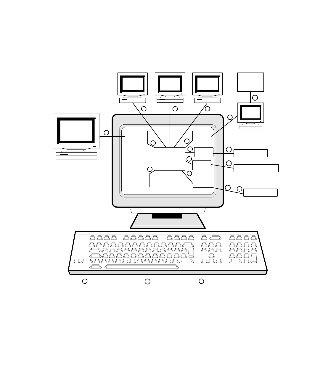
1-7
the ControlAir Server program (casvr.exe), th e n to the ControlAir
Workstation, device managers, and devices.
Still Store,
N
CG, Cart, &
other Video
Devices
S
ControlAir
Workstation
ControlAir
Workstation
ControlAir
Workstation
N NN
iNEWS
newsroom computer system
Network Serial
N
AMCP
Application
C
ControlAir
Server
Application
(casvr.exe)
C
ControlAir
Workstation
S
Device
Manager
C
C
Device
Manager
C
Device
Manager
C
Device
Manager
Communication between
CN
programs in computer
MCS-PC
S
Still Store
S
CharacterGenerator
S
or
N
Figure 1-1 Association of Components in ControlAir
Video
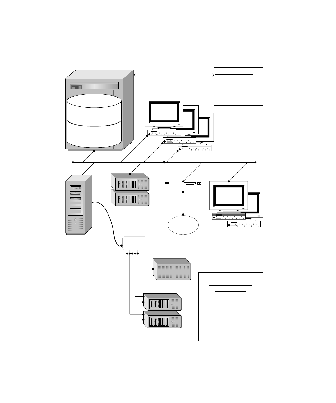
Figure1-2 shows network (TCP-IP) and serial connecti ons between
equipment related to the ControlAir system.
System Archi tecture
Page 20
1-8
iNEWS S erver:
Software
monitor server; /site/config file;
MCSPC Legacy drivers
Database
Rundown& Event List queues
System Map & Resourcequeues
ControlAir
Server
Leitch
ASC 300's
Equinox
16 Port
RS-422
(or RS-232)
iNEWS
Workstations
MCS-PC
AnyMCS Legacy
Playback device
Chyron
iNEWS stations
Writers, etc. create scripts with
production cues. Producer
tracks progress of show, and
can make changes to
production cues even while
the show is on-air.
100Base-T Ethernet or Faster
ControlAir
Workstations
RS-422
or RS-232
Figure 1-2 Typical ControlAir Network Layout
Introdu ction to the iN E WS Contro lA i r™ System
AirSPACE
(AirSPACE DM)
ControlAir Server
Connections
Typically, most ControlAircomponents
(casvr.exe, AMCPapp.exe, & DMs) will
run on the ControlAir Server.
Some DMs (Louth) will attach to their
production devicesvia Equinox or other
multi-port serial board (RS-422 and/or
RS-232). Other DMs,such as the Leitch
ASC 300 DM, and our DM for legacy
MCS-PC's, will connect via Ethernet.
Page 21

1-9
n
ControlAir software can be installed on either th e Mirror Net or the House
Net of the iNEWS hosts. If ControlAir component s need access to other station networking servi ces tha n just iN EWS Serv er s, the n they should be
placed on the House network . In either case , static IP add resses and local
hosts files should be used for all ControlAir compo nent s.
ControlAir Work Flow
After the news staff has entered machine contro l events in scripts, the
producer can download rundowns to ControlAir using the monitor
server in iNEWS.
n
For more information on creating monitor servers, see “Setting up the Monitor Server on iNEWS Servers” on page 4-1.
From the ControlAir Workstation, production personnel, such as the
ControlAir operator, can access playlists for downloaded rundow ns
and control associate d producti on devices to cu e , play, and stop the
production events requested.
When your newsroom staff builds a show, they insert special keywords into scripts, known as production cues. These items include a
word to identify the specific production machine or a machine type,
such as CG or SS, and some information to indicate what they want
that ma c h in e to d isplay.
The following example shows a production cue that instructs the character generator to display two lines of text using a sav ed tem plate
named LOC2:
*CG LOC2
Bob Willhouser
Washington DC
ControlAir Work Flow
Page 22

1-10
Monitor Mode - On
When the monitor server is turned on—usually by the producer, from
the iNEWS Workstation’s Tools drop-down menu—it will read all
production cues in the rundown and build playlists, also known as
event lists, for each device.
After th e mo nitor ser ve r is turned on, it co n ti n u e s to mo nitor the ru ndown, examining every saved story for deleted, new, or updated
events in the playlist.
The monitor server performs as much error checking as i t ca n without
communicating with any broadcast equipment.
The iNEWS ControlAir system is not yet involved. Event lists can be
printed and distributed to the equipment operators, who can control
devices, such as the CG, using trad it iona l meth od s.
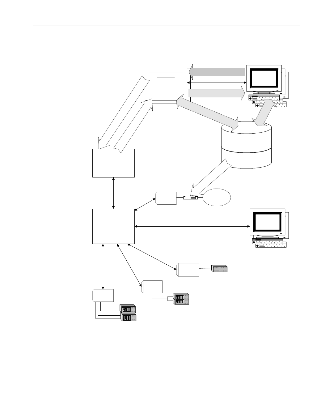
Figure 1-3 depicts communication paths after the monitor server is
turned on from the iNEWS Workstation.
n
Introdu ction to the iN E WS Contro lA i r™ System
For more information about iNEWS utility programs known as monitor servers, see “Setting up the Monitor Server on iNEWS Servers” on page 4-1.
Also, see “Monitor Server’s Error Checking Workflow” on page 4-34 and
“Usin g the Monitor Se rver” on page 4-41.
Page 23
1-11
,
s
t
s
i
l
y
a
l
P
e
t
a
d
p
U
/
d
a
o
l
n
w
o
D
n
e
v
E
AMCPapp
Protocol converter
Maintains link to each
loadedmonitorserver
casvr.exe
Retainsall loaded playlists,
playlist & event status,
statusof attached DM and
ControlAir workstations.
DistributesCommands,
updatedstatus, event
changes & messages.
iNEWS Monitor
Servers
ON: Watchfor added,
deleted, or Modified
Machine Control Events
s
t
LOAD: Send playlists and
n
e
v
updatesto ControlAir
E
,
s
e
i
r
o
t
S
s
e
g
a
s
s
e
M
r
o
r
r
E
,
s
u
t
a
t
S
t
MCSDM
O
B
MCSPC
Monitor Commands
(ON, LOAD, UNLOAD, OFF)
(progress, errors, warnings)
N
:
G
e
t
u
s
i
y
l
d
s
P
t
e
l
m
a
y
i
l
n
i
s
t
,
W
r
i
t
e
r
f
t
r
a
t
s
w
e
o
R
d
Any MCS Legacy
Playback device
Messages
f
o
,
P
a
r
s
e
E
R
v
e
u
n
n
t
d
L
o
i
s
w
t
q
u
e
u
e
Rundown & Event List queues
System M ap & Resource queues
o
t
S
W
s
E
r
e
N
i
v
i
r
m
d
o
d
a
o
l
n
Workstations
n
,
s
iNEWS DB
iNEWS Software
Monitor Server
MCSPC Legacy Drivers
iNEWS
,
s
n
w
s
o
t
n
d
n
e
v
u
E
R
r
e
e
t
t
a
n
e
r
E
C
ControlAir
Workstations
Chyron DM
Chyron
LeitchDM
LouthDM
10base-T
ASC 300's
RS-422
Video Servers
Figure 1-3 Communication Paths after Monitor Mode - On
ControlAir Work Flow
Page 24

1-12
Monitor Mode - Load
As air time nears and the newsroom staff completes the rundown,
someone—usually the producer or equipment (ControlAir) operator—will instruct the monitor server to load the playlist into the
ControlAir system (via the AM CP ap plicat io n program). See “Using
the Monito r Serve r” on page 4-41 and Figure 4-7 on page 4-42 for more
information about the v a r i ous mode s of th e m onitor ser v e r.
As the rundown is downlo a ded to the Co nt rolAir Se rver, th e
casvr.exe program loads it to the ControlAir Workstation, and
loads individual playli sts to the appropriate device manager (DM).
That DM establi shes a connecti on to the device ( if it has not al ready
done so) a nd b e gins its as signed task , such as inserting CG text, checking for availability of video clips, and so forth.
Each DM sends to the ControlAir Server program (casvr.exe) the
status of devices and individual playlists, such as whether video is
available, and so forth. The ControlAir Server then forwards the data
to the ControlAir Workstation and iNEWS monitor server. Error messages are returned to the iNEWS user who loaded the rundown and
the ControlAir operator. The monitor server also displays status for
video clips, such as whether the clip is available, into stories in the
rundown and event lists located in the iNEWS database.
The ControlAir operator can now take control of the playback devices
and tak e the show to ai r.
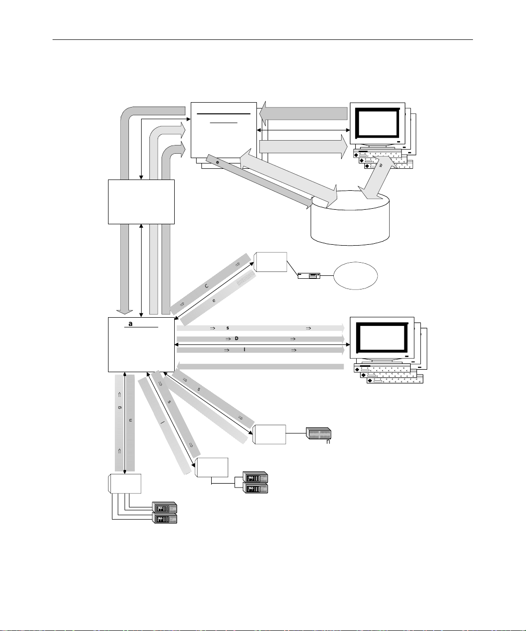
Figure 1-4 depicts communication paths after the monitor server is
instructed to load playlists, commands, status, and user messages
between ControlAir components; note the direction of flow for the
four different kinds of data.
Introdu ction to the iN E WS Contro lA i r™ System
Page 25
1-13
AMCPapp
Protocol converter
Maintains link to each
loadedmonitorserver
Playlist, Event Updates
Messages (progress, errors, warnings)
casvr.exe
Retains all loaded playlists,
playlist& eventstatus,
status of attachedDM and
ControlAirworkstations.
Distributes Commands,
updatedstatus, event
changes & messages.
⇒
P
l
⇒
Status | Messages
⇒
⇐ Playlists | ControlAir Cmds ⇐
Louth DM
a
⇐
S
t
a
t
u
s
|
M
iNEWS Monitor
Servers
ON: Watch for added,
deleted,or Modified
MachineControlEvents
LOAD: Send playlists and
updatesto ControlAIr
A
f
t
e
r
L
A
l
o
r
t
n
o
C
|
s
t
s
i
l
a
y
s
a
l
s
e
P
Event Status, Messages
⇐
y
l
i
s
t
s
|
C
o
n
t
r
o
l
A
e
s
s
a
g
e
s
⇐
M
⇒
|
s
u
t
a
t
S
⇐
⇒
MessagesProgress, errors, warnings
⇐⇐⇐⇐ PlaybackCommands (Channel, Play, Stop, etc.) ⇐⇐⇐⇐
⇒
P
l
a
y
l
i
s
t
s
|
C
S
o
n
t
a
t
r
t
o
u
l
s
A
|
M
e
s
s
a
g
e
i
r
C
m
d
s
s
⇒
O
B
O
A
D
:
E
v
e
n
t
S
⇒
s
d
m
C
r
i
⇐
s
e
g
⇒
Device& Event Status
⇒
Playlist, Event Updates
i
r
C
m
d
s
⇒
⇐
Monitor Commands
(ON, LOAD, UNLOAD, OFF)
(progress, errors, warnings)
N:
G
e
t
u
i
s
l
y
d
s
P
t
e
l
a
m
y
l
i
i
n
s
t
,
W
t
ri
a
t
u
s
(
A
MCSDM
(client)
t
e
v
a
i
l
a
b
l
e
,
ChyronDM
Messages
f
o
,
P
a
r
s
e
E
v
Ru
e
n
n
t
d
L
o
i
w
s
t
q
u
e
C
u
u
e
e
s
d
,
e
t
c
.
)
Rundown & Event List queues
System Map & Resource queues
MCS-PC
⇒
⇒
⇒
Chyron
n
,
iNEWS DB
Any MCS Legacy
Playbackdevice
iNEWS
Workstations
,
s
n
w
s
o
t
d
n
n
e
v
u
E
R
r
e
t
e
t
a
n
e
r
E
C
ControlAir
Workstations
LeitchDM
10base-T
ASC300's
RS-422
VideoServers
Figure 1-4 Communication Paths after Monitor Load
ControlAir Work Flow
Page 26

1-14
Monitor Mode - Unload
After th e show airs, someon e —typically the producer or equipment
(ControlAir) operator—will instruct the monitor server to unload the
playlist from the ControlAir system. The unload mode allows the user
to discon nect fr om the ControlAir Server without turning off the monitor server.
See “Using the Moni to r S e rve r ” on page 4-41 and Figure 4-7 on
page 4-42 for more information about the various modes of the monitor server.
Introdu ction to the iN E WS Contro lA i r™ System
Page 27

CHAPTER 2
Preparing for Installation
This chapter contains the follow ing maj or sec tions:
• Before You Begin the Inst allation Procedure
• Site R e qu i re ments
- Power Requirements
- Environmental Re quirem ents
- Hardware Requir ements
• Configuring & Installing the Host Adapter Card
Page 28

2-2
Before You Begin the Installation Procedure
Setting up ControlAir involves doing tasks in the following places:
• Control A ir S e rv e r
• iNEWS Servers (at the console)
• ControlAir Workstations
n
Device Manager configuratio n is done at the ControlAir Server. You should
consult the iNews Newsroom Computer System Operations Manual for
specific information on iN EWS Serv er s, the console, or various related sys tem operations.
Before you begin installing the ControlAir software, do the following:
• Read the iNEWS C on t r ol A ir Release Notes for the most up-to-date
product and installation information.
• Familiarize yourself with the entire installation procedure
described in thi s manual.
• Ensure the installation CD is available.
• Ensure the site meets all requirements, provided in this chapter .
Site Requirements
The follow ing sections describe cu stomer-supplied comp onents that
make up the iNEW S ControlA ir sy stem . Mo st are hardware compo nents typically purchased from a third party vendor. However, some
items can be obtained through Avid. For more information, contact
your Avid Broadcast Sales representative.
n
Preparing for Installation
It is recommended you install a hand-held, wall-mounted Halon fire extinguisher, or alternative environmentally acceptabl e extinguis her, in the
vicinity of all computer equipment.
Page 29
Power Requirements
Surge protection and an uninterruptible power supply (UPS) are
essential for all system servers. If the computers lose power even for a
moment, the entire system will stop functioning properly.
2-3
w
Most systems are designed to work with single-phase (three-wire)
power cord with a grounded neutral conductor. To reduce the risk of
electric shock, always plug the cord into a grounded power outlet.
For best performance, keep all system power connections on the same
power feed distribution panel. Do not connect fans, lamps, cof fee pots,
or other equipment to the same outlet that is powering the iNEWS
ControlAir equipment.
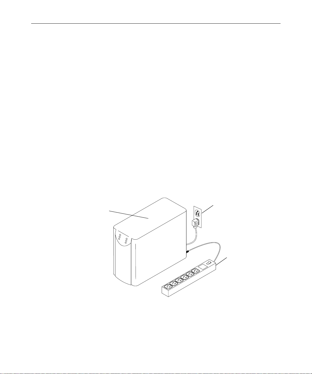
Ensure the UPS has surge protection and a high enough rating to handle all systems connected to it. The rating plate on each system will
help calculate the required rating for the UPS. Figure 2-1 shows how to
connect multiple systems to a UPS using a power strip.
UPS
Grounded AC walloutlet
Power strip
Figure 2-1 UPS Co nnections
Site Requirements
Page 30

2-4
Environmental Requirements
The air conditioning must maintain the operating temperature shown
in Table 2-1. The Avid iNEWS newsroom computer system produces
an estimated heat load of 15, 000 BT U s per hour. Table 2-1 shows the
environmental specifications for a standard iNEWS environment.
c
Avid reserves the right to stop the installation and shut off the
iNEWS equipment if the temperature exceeds 75°F (24°C). Installation will be completed after the air conditioning has been corrected.
T able 2-1 Environmental Specifications
Condi tion Range
Operating temperature 50°F to 75°F (10°C to 24°C)
Storage temperature –4°F to 140°F (–20°C to 60°C)
Relative humidity 20% to 80%
Altitude 0 to 6000 ft (0 to 1829 m)
Hardware Requirements
To install and run ControlAir, use the following tables as a guide for
basic equipment needs. Because development is on-going, req uirements are subject to change without notice. For specifications pertaining to ControlAir, visit Avid’s Web s i te at :
www.avid.com/products/controlair/specs.shtml
Preparing for Installation
Review the latest minimum hardware requirements for all
iNEWS-related product lines on the Web at:
www.avid.com/products/.
Page 31

ControlAir Server
2-5
For a list of qualified PCs, contac t Avid Broadcast Customer Suppo rt
at: +1-800-869-70 09 in the USA
+44-1256-814222 in Europe
+61 2 8877 6888 in Asia/Pacific
Table 2-2 describes the base hardware required to install and operate a
Contr olAir Server and a ssociated device managers .
c
Ensure the time is set correctly on all machines (in cluding date and
AM/PM). In general, this makes it easier to interpret messages from
the system. However, some equipment may cause critical errors if
the time is set differently between systems. For instance, Grass Valley Group’s Pr ofile currently will not corr ectly report the completion
of video clip transfers, so the clips will remain "unavailable" for
playback o n Co ntrolAir.
Table 2-2 ControlAir Server Requirements
Device Minimum Requirement
CPU 450-MHz Pentium
Memory 256 MB of RAM
Keyboard 104 keyboar d
Mouse Windows-compatible mouse
Hard drive 4-GB drive (NTFS format recommended)
Floppy drive 3.5-inch diskette drive; reads and writes to
1.44-MB diskette s
®
II
CD-ROM drive 4X CD-R OM driv e
Site Requirements
Page 32

2-6
Table 2-2 ControlAir Server Requirements
Device Minimum Requirement
Operating system Windows 2000 with Service Pack 2 or Windows
NT Server 4.0 with Service Pack 6a (minimum)
Monitor 15-inch screen
Video card SVGA-c om p a ti ble v id e o card with 2M B of
VRAM. Must supp ort:
• 1024 x 768 resolution
• 256 colors
Network card Windows-compatible 10/100 NIC
n
Server. See “Ports” on page 2-7 and “Configuring & Installing the Ho st
Adapter Card” on page 2-10 for more information.
ControlAir Workstation
To install and run ControlAir Workstation, you wi ll need the base
equipment detailed in T able 2-3.
Table 2-3 ControlAir Workstation Requirements
Device Minimum Requirement
CPU 450-MHz Pentium II
Memory 256 MB of RAM
Keyboard 104 keyboar d
Mouse Windows-compatible mouse
Hard Drive 4-GB drive
A site may also need a serial host adapter card installed on the ControlAir
Preparing for Installation
Page 33

Table 2-3 ControlAir Workstation Requirements (Continued)
Device Minimum Requirement
Floppy Drive 3.5-inch diskette drive; reads and writes to
1.44-MB diskette s
CD-ROM Drive 4X CD-R OM driv e
Operating System Windows 2000 with Service Pack 2 or
Win dows N T Workstation 4.0 with Se rvice Pack
6a (minimum)
Mon i to r SVGA color moni t or (17-i nch reco mmende d)
Video Card SVGA-c om p a ti ble vi de o ca rd with 2M B of
VRAM. Must supp ort:
• 1024 x 768 resolution
• 256 colors
Network Card Windows-compatible 10/100 NIC
2-7
Machine Co n trol PC (MCS-P C)
If your site uses an MCS- PC, for more information, refer to the late st
minimum hardware require me nts on the Web at:
www.avid.com/products/controlair
Ports
Additional Serial Ports
Most CG and SS devices use a serial port (eith er RS-232 or RS-422) to
communicate wit h the ControlA ir dev ice manage r. Many video
devices requ ire an RS-422-on ly serial port fo r each channel. The device
managers use any serial ports that can be addressed through Windows as a standard COM port, such as COM1, COM4, COM9, or
COM32.
Site Requirements
Page 34

2-8
n
See “Configuring &
Installing the Host
Adapter Card” on
page 2-10 for more
informatio n on installing a host adapter ca r d.
Flat telco, cat-3, or cat-5
are all more than adequate.
A less expensive alternative is the optional use of the built-in RS-232 COM1
and 2, and add a Sea-Level two-port RS-422 b oard for COM3 and 4. Refe r to
the appropriate third-party man u fact urer ’s documentation for the host
adapter card.
COM Ports—Digi and Equinox
For scalability, Avid recommends using the Digi AccelePort
8r-(PCI)EIA-422 serial host adapter card in the ControlAir Server, as
shown below.
To perip herals
The 8r-(PCI)EAI-422 host adapter cable assemblies should have eight
DB-25 (male) connectors to which a DB-25 (female) to RJ-45 adapter is
connected. From there, an 8-wire RJ-45 terminated straight cable goes
from the ControlAir Server to the video server, character generator, or
other peripheral device. A custom RJ-45 modular adapter connects to
the device of your choice.
Preparing for Installation
Pinouts for this custom adapter will vary, depending on the device
you are attaching .
Page 35

2-9
Some sites may choose to use oth e r cards, such as the Equinox™
SST-64 PCI serial host adapter card, with the PM16-RJ/422 port module, a s shown be l o w.
Serial Ho s t Ad ap t e r Ca rd Port Mod u le
The PM16-RJ/422 is an external box which conne cts to the SuperSe-
™
Technology (SST) card and has 16 RS-422 ports using RJ-45 sock-
rial
ets. After the SST card is installed, up to 4 port modules can be
attached to each other, in series, for a total of 64 ports (128 ports with
the SST -128). There is no need to install additional boar ds or change
any software, drivers, or settings. Any combination of external port
modules RS-232 or RS-422 with either DB-25 or RJ-45 connectors will
work. So, a site could have an RS-232 port module for CGs and still
stores, and RS-422 for video devices, on th e same SST-64 card. (As of
this publication, DB-9s for the SST do not exist).
Flat telco, cat-3, or cat-5
are all more than adequate.
n
An 8-wire RJ-45 terminated straight cable goes from the Equinox port
module on the ControlAir Server to the peripheral devices. A custom
RJ-45 modular adapter connects the cable to the device of your choice.
A pin-out diagram is located on the b ack of the Equinox RJ/422 port module.
Some manufacturers, including Digi International and Equinox, use "A" to
represent "+" and "B" for "-” while others, such as Sony, reverse "A" and
"B," respectively. Refer to the manufacturer’s documentation for more information.
Site Requirements
Page 36

2-10
Configuring & Installing the Host Adapter Card
Before installing the host adapter card on the ControlAir Server, set
any configuration switches according to the manufacturer’s documentation. Digi and Equinox do cumentation provided with th e cards have
more detailed installation instructions, configuration settings, and
cabling diagrams.
To install the host adapter card, do the following:
1. Unplug the PC.
2. Remove th e computer’s cover.
3. Put on a wrist strap and attach the ground clip to the computer ’s
chassis as shown in Figure 2-2.
c
Semiconductor devices are vulnerable to damage by electrostatic
discharge (ESD). Always use an ESD wrist strap or other grounding
device when opening the computer or removing any circuit boards
from its packing.
Figure 2-2 ESD wrist stra p
Preparing for Installation
Page 37

4. Remove the host adapter card from it s static-proof bag. Hold th e
card b y its outer e dges to avoid touc hing the components and connector on th e ca rd.
Figure 2-3 Host Ada pte r Ca rd
5. Record the card’s serial number so the manufacturer can provide
better service, should the need arise.
6. Remove the expansion slot cover from within the computer.
2-11
Slot cover screw
ISA connectors
(larger)
PCI connectors
(smaller)
Slot cover
7. Locate a free expansion slot (ISA, EISA or PCI) of the proper type
for your card. Match the bottom of the host adapter card with the
structure of the expansion slot.
Configuring & Installing the Host Adapter Card
Page 38

2-12
The correct slot is selected if all the gold pins will fit into the slot
and all spaces in the slot will be occupied.
Align the connector on the adapter card with the system board
connector.
Screw
Card
n
Preparing for Installation
8. Press the adapter card firmly until the connector is seated. Do not
force the card. If you meet with a lot of resistance, pull it out,
inspect th e connector, and try again.
9. Reinstall the screw used for the slot cover to secure the host
adapter.
10. Reconnect any cables that you disconnected.
11. Replace the computer cover.
12. Connect a host cable between the host adapter card and a 16-port
expansion module, such as the PMT6-RJ45/RS-422.
A 16-port expansion module is not required; some sites may use a 4 or 8-port
expansion module .
13. Turn on the computer.
Page 39

Installin g th e D i g i S o ftware Drive r
On Windows 2000-based PC
The Access Resource CD that accompan ies the Digi host adapter c ard,
if inserted and run on a PC with the Windows 2000 operating system,
will provide the following prompt:
The driver for the product (AccelePort 8r-PCI 422)
is included in the Microsoft Windows 2000
installation CD-ROM and is not included with the
Access Resource CD-ROM. However, documentation can
be browsed.
In that documentation, the following installation procedures are provided—a nd included for your inform ation he re:
Use this procedure to install Microsoft Windows 2000 device drivers
for Digi PCI adapters.
1. Ensure the adapter is installed according to instructions as provided earlier in this section or on the hardware installation card
for that adapter.
2-13
n
When you install multiple PCI adapter s of the same type on a Windows system, it is sometimes difficult to determine which adapter you are configuring.
To avoid confu sion, you may wan t to install and configure adapters one at a
time.
2. Turn on the computer and start Win dows 2000.
3. Wi ndows will auto-detect the adapter and search for the correct
device dr iver.
4. If Windows cannot find a driver for the adapter, you will be asked
for the location of the driver. If the driver is on a Digi-supplied
CD, check the CD-ROM box. If you have downloaded the driver,
enter the path to the folder into which you downloaded the driver.
Configuring & Installing the Host Adapter Card
Page 40

2-14
5. Depending on your adapter type, you may be asked to complete
vario u s configu r a ti o n w i za rds or dial ogs. The se wizards and dialogs are fully documented in context -sens itive he lp screens.
6. When the installation is complete, the device is read y to use. There
is no need to restart Windows.
On Windows NT- based PC
The followi ng inst ructions are for installing
on a PC with the Windows NT operating sys tem. Procedures may
vary for other operating
systems.
To install the software driver, do the following:
1. Insert the Digi CD into your CD-ROM drive.
2. Cl i ck the Star t on the Window s ta s k b a r.
3. Select Settings .
4. Select Control Panel. The Control Panel window opens.
5. Double-click on the Network icon.
The Network dial og box opens.
6. Cl i ck the Adap te rs tab.
7. Cl i ck the Add b utton.
8. When the Select Network Adapter dialog box appears, click the
Have Disk butto n.
9. Type the following driver path, with d: indicating your CD-ROM
drive letter.
D:/drivers/windows/nt/acceleport/i386
10. When the Select OEM Option dialog box appears, select Digi
Acceleport 8r-(PCI )EAI -422 A dapt er.
11. Click OK. The driver files are installed.
Preparing for Installation
12. Make any configuration modifications as needed, if prompted.
Page 41

Installing the Equinox Software Driv er
2-15
These sample instructions are for installing
on a PC with the Windows NT operating sys tem. Procedures may
vary for other operating
systems.
To install the software driver, do the following:
1. Insert th e Equinox CD into your CD-ROM drive.
2. Cl i ck the Star t on the Window s ta s k b a r.
3. Select Settings .
4. Select Control Panel. The Control Panel window opens.
5. Double-click on the Network icon.
The Network dial og box opens.
6. Cl i ck the Adap te rs tab.
7. Do one of the following, depending on whether an Equinox driver
exists and is displayed in the Netwo rk Adap te rs list.
a. Select it from the list and click Upda te . Go to step 10.
-OR-
b. If an Equinox driver does not exist in the list, choose Add and
continue to Step 8.
8. When the adapter list is displayed, click the Have Disk button.
9. The Insert Disk dialog box appears.
10. Type the following driver path, with d: indicating your CD-ROM
drive letter.
d:\drivers\ras\disk2
Configuring & Installing the Host Adapter Card
Page 42

2-16
11. Do one of the following:
a. If you are Updating, click Continue and go to step 19.
-OR-
b. If you are adding the driver, click the OK button.
The Select OEM Option dialog box opens. Go to step 12.
12. Select Equinox SST.
Preparing for Installation
13. Click the OK button.
The driver files are installed and a message box appears, telling
you the Equinox driver has been installed.
14. Click the OK button.
The Equinox SST Configuration dialog box appears.
15. Make any necessar y chang es to the COM port number or the
memory block for the ISA adapter cards.
16. Click th e Nex t bu t ton.
17. If the path for the data scope trace files is acceptable, click Finish.
18. A notice indicating that /PC1LOCK was added to the boot.ini
file may appear. Click OK.
19. Click the Equino x Logger i con on the Windows taskbar (a t the bo t-
tom of your screen).
Page 43

2-17
The Equinox Logger - Runni ng window open s, displaying status
messages generated during the driver loading operations.
The following information is displayed:
• Number of adapter cards (boards) found
• Memory range(s) and I/O addresses used
• Names of ports available
• Any failure reasons
• Driver version
20. Click Clo s e in th e N etwork dia l o g box to contin u e with the
installation procedure.
21. The system prompts you to reboot the system. Click Restart and
then click Yes.
Configuring & Installing the Host Adapter Card
Page 44

2-18
Preparing for Installation
Page 45

CHAPTER 3
Installing and Configuring iNEWS ControlAir
This chapter contains the follow ing maj or sec tions:
• Overview of the Setup
- Adding IP Addresses on ControlAir Server
- Adding IP Addresses on iNEWS Servers
- Installing ControlAir Software
- Configuring ControlAir Software
Page 46

3-2
Overview of the Setup
The following tasks must be performed on the ControlAir Server.
• Add IP addresses for ControlAir and iNEWS Servers
• Install the ControlAir software
• Config ure th e Cont rol A ir s oft wa re
These tasks are described in this chapter.
Ideally, all ControlAir Servers, iNEWS Servers, and Cont rolAir Workstations wou ld have each other’s IP addresse s and computer nam e s,
so IP addres se s should be added on the ControlAir Server as well as
on iNEWS Servers. It is not necessary to include IP addresses for Avid
Broadcast workstations or other equipment. See “Adding IP
Addresses on iNEWS Servers” on page 3-3 for more information.
n
The monitor server comm unic ates with the C ontrolAir softwa re only if the
ControlAir Server’s IP address is added to all of the iNEWS Servers’
/etc/hosts files. Procedures for configuring monitor servers are located in
Chapter 4.
Adding IP Addresses on ControlAir Server
This section provides steps for adding IP addresses to the ControlAir
Server.
To add IP addresses to the ControlAir Server, do the following:
1. Use My Computer or the Windows Explorer to open the
\WINNT\system32\drivers\etc folder.
2. Double-click on the hosts file.
3. A dialog box may appear with a list of programs to use for opening the file. Scroll down the list and select Notepad. Ensure that
you uncheck the box to “Always use this program.”
Installi ng and Configuring iNEWS ControlAir
Page 47

4. Click OK. The hosts fi l e open s in a Notepad window.
3-3
IP Addresses for LAN
connected dev i ces
should also be listed.
See “Native Device
Managers” on page 5-4
for more information.
c
5. At the bottom of the file, add line s listing the IP ad dresses and
computer names for iNEWS Servers, ControlAir Servers,
ControlAir Workstations, and MCS -PC machin es (if any). For
example:
192.198.1.1 NRCS-A nrcs-a nrcs-a.yourdomain.com
192.198.1.2 NRCS-B nrcs-b nrcs-b.yourdomain.com
192.198.1.11 CA1 ca1
192.198.1.12 CA2 ca2
192.198.1.21 CAWKSTN1 cawkstn1
192.198.1.22 CAWKSTN2 cawkstn2
192.198.1.31 MCSPC1 mcspc1
192.198.1.32 MCSPC2 mcspc2
6. Save the file and close the Notepad window.
When saving, ensure the newly edited file does not have a .txt
extension. The default options in Windows Explorer will not display
this crucial information. To change this setting, open Windows
Explorer and select Options from the View drop-down menu. In the
dialog box, check Show All Files and uncheck Hide file extension
for known file types, then click OK.
7. Repeat this procedure for each computer on which ControlAir
Serve r, de v i ce manage r, or Control Ai r Workstati o n so f tw a re is
installed.
Adding IP Addresses on iNEWS Servers
For more infor mation
about monitor servers,
see Chapte r 4.
To enable monitor server to communicate with ControlAir, the IP
address of the ControlAir Server must be added to all iNEWS Servers’
/etc/hosts files.
The following procedures explain how to add the ControlAir IP
addresses to iNEWS Servers .
Overview of the Setup
Page 48

3-4
n
c
These steps require the
use of ed, the UNIX line
editor. For more information, see Chapter 10
of the iNEWS Newsroom
Computer System Operations Manual.
ControlAir software can be installed on either th e Mirror Net or the House
Net of the iNEWS hosts. If ControlAir component s need access to other station networking servi ces tha n just iN EWS Serv er s, the n they should be
placed on the House network . In either case , static IP add resses and local
hosts files should be used for all ControlAir compo nent s.
Always back up the /etc/hosts file before editing.
At the console, perform the steps below:
1. Select all servers. Instructions for how to do this is provided in
Chapter 2 of the iNEWS Newsroom Computer System Operati ons
Manual.
2. Type su to log in as superuser and type the superuser password.
3. Type ed /etc/hosts
This command launches the UNIX line editor, and positions the
cursor at the end of the /etc/hosts file, which contains a list of
IP addresses, computer names, and comments, su ch as:
125.1.0.1 NRCS-A nrcs-a nrcs-a.yourdomain.com
125.1.0.2 NRCS-B nrcs-b nrcs-b.yourdomain.com
n
A sample /etc/hosts file is pr ov id ed in App en d ix B .
4. Add addre sses to the file by doing the following:
a. Type a and press Enter to append information to the file.
b. Enter I P addresses, compu ter names, and comments, such as:
192.198.1.11 CA1 ca1 #ControlAir Server1
c. Type a period (.) to stop appending information to the file.
d. (Optional) Type p to print the appended file and verify your
changes.
Do not use an uppercase
W
.
Installi ng and Configuring iNEWS ControlAir
e. Save the file by typing w.
f. Quit ed by typing q.
Page 49

The following example shows the UNIX line editing commands
used in step 4 along with explanations (appearing in parentheses
after th e command):
a (begins append mode)
192.198.1.11 CA1 ca1 # ControlAir Server1
192.198.1.12 CA2 ca2 # ControlAir Server2
192.198.1.21 CAWKSTN1 cawkstn1 # Wkstn1(C ontrolRm1)
192.198.1.22 CAWKSTN2 cawkstn2 # Wkstn2(C ontrolRm2)
. (ends append mode)
p (prints appended file)
w (saves changes by writing the file to the disk)
362 (ed responds by displaying file size)
q (quits the edit sessi on)
Installing ControlAir Software
It is possible to install all ControlAir components on a single computer
or to install them separately. Typically, ControlAir Server software and
device managers (DMs) are installed together on ControlAir Servers
and the ControlAir client software is installed on ControlAir Workstations—computers in each control room where ControlAir will be used.
See “ControlAir Co m p o ne nt s” on page 1-4 for more information.
3-5
c
The procedure in this
manual provides steps
for a typical installation.
If you are planning to install either the AirSPACE or Grass Valley
Group Device Manager , there is other software that must be
installed prior to the ControlAir software. For the AirSPACE DM,
install Avid AirSPACE NT Applications. For the GVG DM, install
the Profile software for non- Profile PCs. If the GVG DM is to be
used with EditStar, you must also install the EditStar Server Interface for ControlAi r. For more inform a tio n, refer t o the speci fic
Device Manager Guides available for these DMs, located in the
Docs folder on the ControlAir Install CD.
To install the ControlAir software, do the follow ing:
Overview of the Setup
Page 50

3-6
1. Insert the ControlAir Installation CD into the computer’s
CD-ROM dr ive .
2. Navigate to the CD drive. For instance, on a computer running the
Windows NT operating system, use Wi n d ows NT Explorer and
select the CD-ROM drive from the tree-style directory listing.
3. Double-click the Setup.exe file to launch the Setup program.
n
During installation, the Setup program will check for a valid operating system (OS). Exactly when this check is done varies, depending on selections you
make during the installation procedu re. If a valid operating system is not
found, a message indicating an unsupported OS will appear.
Your only option will be to exit the Setup program.
Installi ng and Configuring iNEWS ControlAir
Page 51

When the Setup program launches, the ControlAir Setup dialog
box opens.
3-7
n
4. Click Ne x t.
A dialog box will appe ar with a notice stating the Setup program wil l change
the main directory name from old name(s), if any—such as iNEWS—to Avid.
If you have a device manager not provided by iNews, LLC or Avid Technology, Inc. , you may n eed to r ein stall it. When this di alog box appears, continue
the setup process by clicking Next.
Overview of the Setup
Page 52

3-8
5. When the License Agreement dialog box appears, read the user
license agreement information.
If you accept the terms of the agreement, click Yes and go to step 6.
If not, click No and the Setup program will close.
Installi ng and Configuring iNEWS ControlAir
Page 53

3-9
6. When the Customer Information dialog box appears, enter a user
name and company name in the appropriate fields.
Overview of the Setup
Page 54

3-10
7. Click Next to cont inue . Th e Select Program F iles Loc atio n dialo g
box appears.
8. Do one of the following:
a. If the default Destinatio n Folde r is acceptable , click Nex t. Go
to step 9.
-OR-
b. If the default Destination Folde r is not acceptable, cli ck
Browse a nd choose another locati on, then cli ck Next. Go to
step 9.
Installi ng and Configuring iNEWS ControlAir
Page 55

9. The Setup Type dialog box appears.
3-11
Step 9a is reco mmended for the
ControlAir Server.
n
Highlight each type—with a single c lick—to see a description of
that Setup type, provided in the Description section on the left
side of the dialog box.
When you click Next in the Setup Type dialog box, the Setup program will
verify whether the selected destination has enough space for the type chosen. If
it does, the Setup program continues. If not, a warning messag e will appear
and the Setup program will r eturn to the Select P r ogram Files Locatio n dialog
box. See step 7 on page 3-10.
Do one of the following:
a. Select Complete if installing all ControlAir components—
server, device manager, and client soft ware—on a single computer. Go to step 11 on page 3-13.
-OR-
Overview of the Setup
Page 56

3-12
b. Select Custom if you want to select individual components to
install, such as installing only ControlAir Server and device
manager s oftware on a compute r. The Sele ct Components dialog box appears. Go to step 10.
-OR-
c. Select GVG Profile or Profile XP if installing software related
to the G rass Valley Group ’s Profiles, high resoluti on video
servers. Go to step 13 on page 3-17.
-OR-
d. Select Workstation Only if installing the client software only
on a Contro lAir Workstation. Go to step 13 on page3-17.
10. When a Custom Setup is chosen (as in ste p 9b ) , th e Se lect Components dialog box appears.
As each component is highlighted, a description is provided on
the right.
Installi ng and Configuring iNEWS ControlAir
Page 57

3-13
n
Individual Device Manage r subcomponen ts ar e expla ined in Device Manager
Guides for each device, which are provided on the ControlAir Install CD. For
more information, refer to the guide for your devices.
To install component s for the ControlAir Ser ver and de v ice managers on a single computer, ensu re that the following primary
components are checked:
• ControlAir Manager
• Control A ir S e rv e r– if selected, go to step12 on pag e 3-16.
• Device Managers, and any of its secondary components, as
listed below:
- Device Manager Program Files – select this option to install
program f iles for th e Lou th, MCS, and Chyron device managers.
- Example DMP files – select this option to install samp le
DMP files.
-AirSPACE Device Manager – select this option to install
program files for the AirSPACE DM. Doing so will result in
additional dialog boxes appearing as part of the setup process. Go to step 11 on page 3-13.
n
- Grass Valley Group Device Manager – select th is option to
install program files for the GVG DM. Doing so will result
in additional dialog boxes appearing as part of the setup
process. Go to step 11 on page 3-13.
The other p rimary com po n en t av ai l ab l e in t he Sel ec t Co mp on e n t s di al og box
is for ControlAir Workstation s. Selecting all compo nents in the list would be
the same as selecting a Complete setup as shown in step 9a on page 3-1 1.
11. This step only appli es to Comp let e Setu ps or Cust om Se tup s when
the Dev i ce Managers component is chosen.
If the Complete Setup type is not chosen or if the AirSPACE DM
and Grass Valley Group DM components are not chosen for a Custom Setup, you may skip this step and go to step 12.
Overview of the Setup
Page 58

3-14
If the AirSPACE and GVG DM components are chosen, additi onal
dialog boxes will appear as part of the setup process—four of
which are described in this step:
• For Complete Setups or for a Custom Setup in which the GVG DM
is selected, a dialog box will appear asking if the site also has EditStar.
Select the appropriate radio button and click Next.
• For Complet e Setups or for a Custom Setup in which the AirSPACE DM is selected, a d ia log box wi ll appear asking if software
pertaining to Avid’s LaunchPad or MissionContr ol is installed.
Installi ng and Configuring iNEWS ControlAir
Page 59

3-15
a. Choose Yes if the requested software is already installed.
-OR-
b. Choose No and the Setup program will exit automatically.
• For Complete S e tu p s an d or f or Custo m Se tups in which the Air-
SPACE DM and/or GVG DM are selected , a dialog box similar to
following will appear:
It pertains to GPI Remote Panel support for either the AirSPACE
DM, the GVG DM, or both.
a. Click Yes, if the driver software is already installed.
-OR-
b. If not, click No. The Setup program wi ll exit autom atic ally.
Overview of the Setup
Page 60

3-16
12. This step only a ppli es to Compl et e Setup s or Cust om Se tups w hen
the ControlAir Server component is chosen. The Create the ControlA ir Workstation Reserve Ove rride Password dialog box
appears.
To set a password, type an Override passwor d in the text box. The
password is case-sensitive and can be a combi nation of letters and
numbers.
n
Installi ng and Configuring iNEWS ControlAir
The Override passwo rd mu st be set during installa tion ; it can be changed
through the ControlAir Server program. See “Setting the Override Pa ssword” on page 6-7 for more information. The purpose of the password is to
prevent a show from being reserved by a second ControlAir Workstation
while under the control of a first workstation. Setting this password ensures
that only authorized personnel may take control of the show from another
workstation, which is useful should a workstation computer fail after it was
used to reserve a rundown.
Page 61

3-17
13. Click Next. The Select Programs Menu Folder dialog box opens.
n
Program icons are used to launch software programs. For instance, a user
clicks the Start button, selects Programs from the menu, then chooses the program icon for the software the user wants to run. By default, most program
icons are placed in the Start menu under the Programs option. But , the Select
Programs Menu Folder dialog box (shown above) allows an installer to choose
an alternative location in the Start menu, during the setup process.
14. Do one of the following:
a. Click Next if the defau lt Program Folder setting for the pro-
gram icons is acceptible.
-OR-
b. Type another fo lder pathname in the Program Folder text box,
if the defaul t setting is unacceptable, then cl ick Next.
Overview of the Setup
Page 62

3-18
Settings will vary
according to selections
made in previous steps.
15. Click Next. The Start Co pying Files dialog box appears, displa ying
the current settings for installation.
16. Do one of the following:
a. To review or change any setting, click the Back button.
-OR-
b. To continue the setup and start copying files, click Next. Go to
step 17.
Installi ng and Configuring iNEWS ControlAir
Page 63

17. The Setup Status dialog box appears, displaying a progress bar
that indicates the percentage of installation completed.
3-19
When the progress bar reaches 100%, anot h e r dialog box appears;
which one depends on what type of installation you chose in step
9 on page 3-11:
• If you chose a Comp lete or Custom in stallation that included
Control A ir S e rver softw a re , go to st e p 18 .
• If you chose a Custom installation that did not include the
ControlAir Server softw are, a Workstation Only installation,
or GVG Profile or Profile XP installation, go to step 23 on
page 3-22.
Overview of the Setup
Page 64

3-20
18. If you are installing ControlAir Server components, an Information dialog box will appear with instructions on how to set up Dr.
Watso n notifications on the serve r.
19. Click OK.
20. The Dr. Watson for Windows NT dialog box appears.
Since most Cont rolAir Ser vers are left to run unobserv e d, visual
notification of Dr. Watson issues is not needed. Instead an audible
alert is provided. The default audio file is a WAV file called
Installi ng and Configuring iNEWS ControlAir
Page 65

3-21
alert.wav. However, this setup dialog box allows the installer to
select an alternative audio file, so do each of the following:
a. Ensure the correct pathname to the WAV fi le is provided. The
default l o cation is in the Program Files directory, as shown in
the above graphic.
b. Ensur e that Vi sual Notifi cation is unchecked and Sound Noti-
fication is checked.
c. Click OK.
n
c
The audible alert will only work if the ControlAir Server has a sound card and
speakers.
21. A Question dialog box will appear, confirming whether you want
the ControlAir Server to automatically logon after reboot? Do one
of the following:
a. Cl i ck No i f you do not want to enable a utomatic logon. Go to
step 23 on page 3-22.
-OR-
b. Click Yes if you want the ControlAir Server to automatically
log on after rebooting. Go to step 22 on page 3-22.
If automatic log on is enabled, the password is stored in the server’s
registry, which means anyone with access to the computer has ac cess
to the password. You can bypass the auto logon function after it is
enabled by holding down the Shift key during the boot or logoff
process.
Overview of the Setup
Page 66

3-22
22. The Logon Information dialog box will appear.
Enter your User Name, Password, and Domain, then click Next.
23. The Setup program will determine whether any previous version
of the ControlAir(formerly known as BCS) software is installed.
a. If not, go to step 27 on page 3-25.
-OR-
b. If there is prev ious softwar e installed , a dialog box will a ppear
as shown:
Click Yes, then go to step 24 on page 3-23.
Installi ng and Configuring iNEWS ControlAir
Page 67

24. The Setup program will search for previous configuration files
and registry settings. If it finds them, the copying will proceed as
shown:
If it does not find them, then a prompt will appear allowing you to
provide the path to their location.
3-23
Fill in the path and click Next. The copy ing will then proceed .
25. After the configur ation f iles and registry settings are copied, if a
previous version of ControlAir (formerly known as BCS) exists,
Overview of the Setup
Page 68

3-24
the following notification is displayed: Click OK.
The Setup program will then inform you that it will launch the
previous version’s uninstall program. Click OK.
26. The InstallShield Wizard displays its Welcome screen.
a. Ensure that Remo ve i s selected.
b. Click Next.
c. Respond to any prompts as needed.
d. When the uninstallation is complete, click OK.
Installi ng and Configuring iNEWS ControlAir
Page 69

27. The InstallShield Wizard Complete dialog box will appear and
prompt you to restart the computer . Do one of the following:
a. Select Yes to restart the compute r, remove the Install CD , and
click Finish.
-OR-
b. Select No to close the Setup program wi thout re starting the
computer.
3-25
n
When installing the software, the computer must be restarted after setup is
complete. If the server and device manager software was installed, the
ControlAir Server and device manager programs will launch automatically
follo w in g th e reboot. Se e “Overview” on page 6-2 for more inform ati on.
Configuring ControlAir Software
Because ControlA ir can inte rface with a var iety of dev ices, s uch as
character generators, still store machines, and video playback devices,
the specific steps for configuring the system will vary. However, the
major steps to configuring ControlAir are:
• Setup the ControlAir Manager program by editing the
autostart.ini file.
• Edit the Device Manager Profile (DMP) file for each device.
The first step is explained in this section. See “DMP Configuration
Files” on page 5-6 for more on edi ting DMP files.
Setup ControlAir Manager
The ControlAir Manager progra m monitors C ontrolAir components,
including device managers, on the ControlAir Server. If one stops running, the ControlAir Manager w ill restart it automatic al ly.
n
ControlAir Manager can also monitor third-party device managers.
Overview of the Setup
Page 70

3-26
To determine which programs to monit or, the ControlAir Manager
looks for the Start Sequence list in the autostart.ini file. A default
version of this file—shown in Appendix B—is installed with the
ControlAir Server software in the Avid/ControlAir directory. A
sample copy is also provided in the Examples folder, which is located
in the Avid/ControlAir dire ctory too.
c
Do not use ControlAir Manager for video device managers, such as
DMAirPlay, that do not protect playing clips when it starts up. For
more information, refer to the Device Manager Guide for each specifi c device—located on the ControlAir Install CD.
The autostart.ini file contains two lists:
• The Start Sequence list appears first in the file and contains a line
for each program monitored by the ControlAir Manager, in the
order in which they are to be started.
• The Samples list appears second in the file and contains standard
sample lines for other devices co m monly used.
Installi ng and Configuring iNEWS ControlAir
Page 71

3-27
The following is an example of the two lists as they appear in the
default ve rsion of th e autostart.ini file:
[Start Sequence]
casvr.exe
AMCPapp.exe
MCSDM.exe dmp\mcsdmss.dmp
MCSDM.exe dmp\mcsdmcg.dmp
LouthDM.exe dmp\Louth.dmp
[Samples]
;This section is ignored by the ControlAir Manager
ChyronDM.exe dmp\ChyronDM.dmp
LouthDM.exe dmp\pdr1.dmp
MCSDM.exe dmp\clipbox.dmp
LouthDM.exe “c:\My Device Profiles\AirSPACE-2.dmp”
c
n
The Start Sequence list must begin with the name of the ControlAir
Server program, casvr.exe. Next comes the Avid Machine Co ntrol
Protocol Application filena me, AMCPapp.exe. The remaining lines
contain two columns of information pertaining to various device managers—one device per line. The first column has the name of the
device manager program and the second provides the pathname for
the DMP configuration file. If no DMP file is specified, the device manager will start, but an Open File dialog box will appear, r equesti ng the
user to specify a DMP file. See the Device Manager Guides on the ControlAir Install CD for more information on creating and editing DMP
files fo r each device.
If no DMP file is spec ified, the ControlAir Manager cannot automatically restart the DM.
It is highly recommended that a copy be made first as a backup before editing
the autostart.ini file.
Overview of the Setup
Page 72

3-28
To edit the autostart.ini file, use the Windows Notepad pro gram.
c
When saving the newly edited INI f ile, ensure that it do es not have a
.txt extension. The default options in Windows Explorer will not
display this crucial information. To change this setting, open Windows Explorer and select Options from the View drop-down menu.
In the dialog box, check Show All Files and uncheck Hide file extension for known file types, then click OK.
T o prevent ControlAir Manager from automatically res tarting a devi ce
program, the line for that device must be removed from the Start
Sequence list in the autostart.ini file. It can be deleted from the
list completely or moved to the Samples list.
In the following example, the default line for a character generator—MCSDM.exe—is and replaced with the standar d Chyron device
manager line—ChyronDM.exe—originally provided in the Samp les
list. Compare the list below with the standard default listings shown
on page 3-27 to spot the edit.
[Start Sequence]
casvr.exe
AMCPapp.exe
MCSDM.exe dmp\mcsdmss.dmp
ChyronDM.exe dmp\ChyronDM.dmp
LouthDM.exe dmp\Louth.dmp
[Samples]
;This section is ignored by the ControlAir Manager
MCSDM.exe dmp\mcsdmcg.dmp
LouthDM.exe dmp\pdr1.dmp
MCSDM.exe dmp\clipbox.dmp
LouthDM.exe “c:\My Device Profiles\AirSPACE-2.dmp”
Installi ng and Configuring iNEWS ControlAir
Page 73

CHAPTER 4
Setting up the Monitor Server on iNEWS Servers
After the iNEWS Cont rolAir soft ware is insta lled , you mu st set up
monitor servers on iNEWS Se rvers to use Con trolAir.
Do not confuse the monitor server in this chapter with server hardware or file servers, which are computers with the iNEWS database
and running the iNEWS Server software. If referenced in this chapter,
those computers are called iNEWS Servers, NRCS-A, NRCS-B, and so
forth. This chapter explains setup and use of the utility program
known as the monitor server. There are various types of these utility
programs, called servers, which perform a multitude of tasks. See the
“Servers” chapte r of the iNEWS Newsroom Comp uter System Operations
Manual for more information.
This chapter contains the follow ing maj or sec tions:
• Overview
• Configuring Monitor Servers
- Configuration Summary
- Configuration Details
• Using Monitor Server
Page 74

4-2
Overview
A monitor server is a utility program—running on the iNEWS newsroom computer system—that che ck s a sh ow’s event requests for
error s, creat e s composite and eve nt lists, and sends playli sts to
ControlAir.
A monitor server must be assigned device and mailbox numbers—typically, these numbers are the same, which ma kes the configuration easier to remember. A device number is chosen for monitor
server so iNEWS recognizes the server (utility program) as a valid
device. The device number must be entered in the system’s co nf i gu r a tion file. The mailbox number must be assigned to both the show’s
monitor server and its rundown queue.
n
A mailbox is an activation mec hani sm for a server (utility ) progra m, so if a
queue has a mailbox number matching a server program, then that server is
the one activated or “awakened” whenever something happens to the queue.
See Chapter 14 in the iNEWS Newsroom Computer System Operations
Manual for more information on mailboxes and other server programs.
The mailbox ena ble s iNEWS to notif y the m on itor ser ver of change s
made to a r undown queue—the one sharing the same mailbox num-
ber—while that show is monitored. The mon itor server then update s
composite and event lists, if necessary.
The monitor server is turned o n when a user at an i NEWS Workstation
turns it on. When on, monitor server checks its assigned rundown for
production cues, and builds playlists.
It continues to monitor the rundown for changes and performs as
much erro r ch ecking as it ca n—by comparing production cues with
styles located in the SYSTEM.RESOURCE queue—without commu nicating with any broadcast equipment, including ControlAir. See
“Monitor Mode - On” on page 1-10 and Figure 1-3 on page 1-11 for
more information. Also, to learn more about styles and how monitor
checks fo r errors, see “Styles” on page 4-33.
Setting up the Monitor Server on iNEWS Servers
Page 75

4-3
The monitor server loads data to the ControlAir system when a user
instructs it to do so from an iNEWS Workstation. The communi cation
paths between monitor server and ControlAir, at this point, is
explained in more detail in “Monitor Mode - Load” on page 1-12. See
also Figure 1-4 on page 1-13 and “Using the Moni tor Server ” on
page 4-41.
n
It is recommended that producers turn the monitor server on ea rly so it can
check the rundown queue throughout much of the show’s development.
Instructing the monitor server to load data should be done later, such as just
before taking the show to air.
Some sites use the monito r se rver alone—without any direct connection to devices or ControlAir—to check machine control events within
scripts for errors and prod uce playlis ts t hat personnel can print out or
ref er to durin g broadcasts.
Configuring M o n it o r Se rvers
When configuring monitor servers, there are certain tasks that must be
performed on the iNEWS Servers at the console, and at an iNEWS
workstation. If your site already has the Machine Control System
(MCS), mu ch of this work may alre ady be done . These task s must be
completed to download playlists and updates to the ControlAir system.
This chapt e r ass umes:
• Your site has a fully function ing network.
• Your newsroom compu te r system servers are operational and run-
ning the iNEWS Server software.
• All iNEWS Servers are connected to a console multiplexor, to
which Avid Broadcast Customer Support technici ans have dial-in
access.
Configuring Monitor Ser vers
Page 76

4-4
• The person pe rf orming the in stallation has attended an iNEWS,
AvidNews, or NetStation system admi nistrat ion course or h a s
equivalent experience. This includes having a worki ng knowledge
of ed, the UNIX line editor and selecting servers at the console.
n
It is highly recommended that you have an iNEWS Newsroom Computer
System Operations Manual available while conducting procedures found in
this chapter. Selecting servers is explained in Chapter 2 of the operations
manual and the UNIX line editor is explained in Chap ter 10.
Configuration Summary
The set-up procedure has the following steps: Each step is explained
further in “Configur ation De tails” on page 4-4.
1. Creating a Monitor Server for Each Show (page 4-5)
2. Creating Composi te and Event List Queues (page 4-12)
3. Set Up Queue and Story Forms (page 4-15)
4. Assigning Forms to Queues (page 4-17)
5. Create an Entry in the SYSTEM.MAP Story (page 4-19)
6. Updating the iNEWS System Dictionaries (Optional) (page 4-28)
7. Some configurations require updating styles in the
SYSTEM.RESOURCE story. For more information on how to do
that, see “Styles” on page 4-33.
Configuration Details
The following steps do not include setting up external devices, such as
character generat ors and still stores, whic h play broadc ast event s.
Refer to the manufa ct ur er’s documentation, provided with the device,
and to th e Device Manager Guides, provided on the ControlAir Installa-
tion CD, for more configura tion det ai ls.
Setting up the Monitor Server on iNEWS Servers
Page 77

The configuration procedure comprises the following steps:
Step 1: Creating a Monitor Server for Each Show
4-5
This section assumes
rundown queues for the
shows being monitored
already exist. If not, create the m b e fo r e continuing. Refer to the
iNEWS Newsroom Computer System Operations
Manual for more infor-
mation.
Valid standard mailbox
numbers are 1 through
4096 . For more on mailboxes, see “Using Mailboxes” in Chapter 14 of
the iNEWS Newsroom
Computer System Operations Manual.
n
To create and configure a monitor server, do the following:
1. Check the configuration file (/site/config) and choose the next
available device number for the monitor server, from the range of
3-digit numbers reserved for use by your system’s server programs, such as 201 to 300 .
2. Choose an available mailbox number. For simplicity, this can be
the same 3-digit device number. Do the following:
a. Use the list console command to ensure no other device is
using the mailbox number you have chosen.
For instance, to check mailbox 266, type:
list mailbox=266 c
Information similar to the following appears:
DEV DEVICE_TYPE COMPUTER CCU PRINTER SPEED OPTIONS DEVNAME
For other
list
command options for determining mailbox assignments of
queues and servers, see “Using the list Command to View Assigned Mailboxes” on page 4-11.
b. If you see the device configuration header (as shown in step
2a) with no information below it, then no device has that mailbox and you can use that number. However, if configuration
information for a device a ppears bel ow the header, that device
has the same mailbox as the one you chose. Therefore, choose
another mailbox number and repeat step 2a.
Configuring Monitor Ser vers
Page 78

4-6
n
c
Changing the configuration file requires the
use of ed, the UNIX line
editor. See Chapter 10 of
the iNEWS Newsroom
Computer System Operations Manual for more
information.
If the mailbox number is already being used, and you must choo se another,
you may want to try another device number for the monitor server as well.
Typically, mailbox numbers match server program device numbers, although
this is not required. However, the mailbox number you select must be
assigned to the queue monitored by the server program. Mul t iple queues c an
share the same mailbox number, but care must be take to avoid conflicts. See
“Assigning the Mailbox to the Rundown Queue” on page 4-10 for more
information.
3. Add the mon itor ser ver t o the /site/config file on each iNEWS
Server—such as serve r A and ser ve r B in a dual se rver sy s te m —
by doing the following:
Always back up the /site/config file before m aki ng a ny
changes. See “Changing the Configuration File” in Chapter 11 of the
iNEWS Newsroom Computer System Ope rations M anual for more
information.
a. At the console, select all iNEWS Servers. Instructions for how
to do this is provided in Chapte r 2 of the iNEWS Newsroom
Computer System Operations Manual.
b. Use the ed comm and to open an d edit the conf igurat io n file,
by typing:
ed /site/config
1259
After you press Enter , the editor responds by displaying a
number, as shown, indicating the file size expressed as the
number of characters, including spaces and returns.
c. Add the monitor server’s device number to the servers line
in the host definition for the iNEW S Server that will run the
monitor server program. For instance:
servers 261 263 265 267
The device number 267 is added to the servers line in this
example.
Setting up the Monitor Server on iNEWS Servers
Page 79

4-7
n
Do not confuse the configuration line, which
starts with server, and
the servers line mentioned in 3c (page 4-6),
which lists device numbers.
Divide your server programs evenly among your iNEWS Servers to distribute the load they put on your system. For instance, put odd numbered programs on server A and even numbered ones on server B. Additionally, ensure
that you also add the configuration line for the monitor server to alternate
host definitions for your iNEWS Servers. This ensures it can run on the surviving computer should one of your iNEWS Servers stop functioning. A sample configuration file is provided in Appendix B; it includes poin ters
indicating where in the file informati on is added, as descri bed in this procedure.
d. Add a configuration line for the monitor s erver in the host
definition belonging to the iNE W S Serve r that will run the
server program. This line begins with the word server and
contains the mailbox number assigned to the monitor server .
The format for server programs’ configuration lines are:
server <device#> <type> <mailbox> <device name>
Parameter Description
device #
type
The device number assigned to the server program. This 3-digit number must also be listed
in the servers line in a host definition.
The type of server program is monitor.
mailbox
device name
The mailbox the server program uses. Valid
standard mai lbox nu mbers ar e 1 t hrou gh 409 6.
This number typically matches the server program’s device number.
Monitor servers do not use a device name;
enter a hyphen (-).
Configuring Monitor Ser vers
Page 80

4-8
Comments appearing
after the semicolons (;)
are optional.
Do not use an uppercase
(W) in step 3e. See Chapter 10 in the iNEWS
Newsroom Computer System Operations Manual
for more information.
The following are sample configuration lines for various server
programs:
server 256 action 256 actphon ;action svr
server 257 distribution 257 devname1 ;dist server
server 258 parallel 258 devname2
server 259 keyword 259 key1 ;keyword server
server 260 seek 260 seek ;seek server
serve r 261 fts see k 2 61 - ;fts se ar ch es
serve r 262 fts ind ex 2 62 - ;fts in de xi ng
serve r 263 pri nt 263 - ;print se rv er
serve r 264 mon ito r 2 64 - ;moni to r se rver
serve r 265 mon ito r 2 65 - ;moni to r se rver
serve r 266 mon ito r 2 66 - ;moni to r se rver
serve r 267 mon ito r 2 67 - ;moni to r se rver
e. When you finish making changes to the configuration file,
save your changes by typing:
w
f. When you press enter, a number will appear, such as 1279,
indicating the file size. You can then exit the UNIX line editor
by typing:
q
4. (Optional) Test your configuration changes. See “Testing the Site
Configuration File After Changing” in Ch apter 11 of the iNEWS
Newsroom Computer System Operations Manual for more information.
After editing the configuration file (/site/config), it sh oul d be ba cke d up
n
to tape. For more information about backing up site files, see the iNEWS
Newsroom Computer System Operations Manual.
Before the monito r server can be used, two mor e tasks must be completed:
Setting up the Monitor Server on iNEWS Servers
Page 81

• Reconfiguring the system to incorporate the new device (monitor
• Adding t he mon ito r s e rve r’s mailbox to the rundown queue it will
These tasks are covered in the next two sections.
Reconfigure the System
4-9
server) into your system’s operation.
be monitoring.
Y ou do not need to stop
anything to reconfigure
the system.
To reconfigure the system, do the following:
1. At the console, select the master computer (typically server A).
2. Type su to log in as superuser and type the superuser password.
3. Type:
NRCS-A# offline
4. Type:
NRCS-A# configure
5. When the prompt retur ns, bring the system online again by typing:
NRCS-A# online
A message similar to the following will appear:
A Wed Oct 3 00:18:58 2001 msg System being configured
6. After you see the System being configured message, exit
from superuser mode. (CTRL-D)
Unlike other utility programs, it is not necessary to start a monitor
server when you add it to the configuration file. It starts when someone uses the monitor on or monitor load command for the rundown queue to which you have assigned the monitor server. See
“Using the Monitor Server” on page 4-41 for more informati on.
Configuring Monitor Ser vers
Page 82

4-10
Assigning the Mailbox to the Rundown Queue
Mailboxes are assigned
to queues in the same
way other dat abase
traits are—using the
Queue Properties dialog box. See Chapter 5
in the iNEWS Newsr oom
Computer System Operations Manual for more
information.
After you choose the monitor server’s mailbox number an d verif y that
it is not used by another device, you must also assign it to the show’s
rundown queue, being monitored by the monito r server.
For instance, the rundown queue in the following procedure is
SHOWS.6P.RUNDOWN, and the mailbox being assig ned is number 267.
To assign a mailbox to the rundown queue, do the following:
1. Log in as a system administrator—that is, with a superuser
account—to an iNEWS workstation.
2. Navigate to the rundown queue, such as the queue named Rundown located in the SHOWS.6P directory.
3. Right-click on the queue and select Properties from the pop-up
menu. The Queue Properties dialog box will appear.
4. Click on the Maintain tab.
Setting up the Monitor Server on iNEWS Servers
Page 83

5. Select the Standard radio button located in the Mailbox section.
6. Type in the mailbox number, such as 267.
7. Click OK to save changes.
Using the list Command to View Assigned Mailboxes
Variations of the list command can be used at the consol e to determine mailbox assignments for specific devices, queues, and so forth.
Since multiple queues can share the same mailbox, you can list all
queues and director ies in the dat abase that ar e using a cer tain mail box,
such as 267. To do this, type:
list mailbox=267 d
To find out which monitor server mailboxes are assigned, type:
list c monitor
4-11
The system displays configuration information for your system’s monitor servers, similar to the following:
DEV DEVICE_TYPE COMPUTER CCU PRINTER SPEED OPTIONS DEVNAME
S264 mon it or A N 26 4
S265 mon it or B N 26 5
S266 mon it or A N 26 6
S267 mon it or B N 26 7
NRCS-A:
The mailbox number assigned to each monitor server appears in the
PRINTER column and begins with the letter, N.
To see if any servers are assigned a certain mailbox number, use the
following format: list mailbox=<mailbox number> c
Configuring Monitor Ser vers
Page 84

4-12
c
Two rundown queues can share the same mailbox, but they should
never be monitor ed s imultaneously. If two r undowns share th e same
mailbox number, ensure that both their monitor servers do not run
simultaneously; otherwise, results could be unpredictable.
To check whether mailbox 267 is assigned to a server program, type:
list mailbox=267 c
Step 2: Creating Composite and Event List Queues
The monitor ser ver sc ans st or ies f or pr o duct ion cu es and bui lds li sts of
machine control events, which can be referenced or used to transmit
data to pr odu ction devi ce s, such as character gener ators (CGs), vi deo
servers, and still store machin e s. These lists, known as composite and
event lists, are option al, yet valuable, resou rces for a show’s director
and production device operators. An event list contain s detai l s for a
specific device, whil e a compo s ite list cont ains statu s info rm ation f or
all devices connected through ControlAir.
You may want to create only composite and/or event lists for certain
production devices. If you do not create list queues for some devices,
the monitor server will not create lists.
For these lists to exist, queues for them must be cr eated—if th ey do not
already exist—and they must be “mapped” to the monitor server so it
knows where to put composite information and event lists.
The following procedure explains how to create queues. For more on
mapping them, see “Create an Entry in the SYSTEM.MAP Story” on
page 4-19.
To create and configure the composite and event list queues, do the
following:
1. At an iNEWS workstation, log in as a system administrator—or
user with authority to create queues in the iNEWS database.
2. Navigat e to and select the directory (f ol d e r ) created to ho l d th e
queue you want to create.
Setting up the Monitor Server on iNEWS Servers
Page 85

3. Do one of the following:
a. Click on the T ools drop-down menu, then select New Queue.
-OR-
b. Right-click on the folder in the Directory panel, and choose
New Queue from the pop-up menu.
A new queue appears under the folder you selected. The
New-Queue appears at the end of the list of existing queues.
The title, New-Queue, is highlighted, so you can rename it.
4-13
n
4. Type the name of the new queue, such as COMPOSITE or CG1.
The pathname of each device’s event list queue is a combination of the event
list director y and the dev ice manage r’s name. For instance, if you want an
event list for the 6PM show that has a character generator called CG1, you
Configuring Monitor Ser vers
Page 86

4-14
may select to place the event list queue in the SHOWS.6P directory. The pathname would be SHOWS.6P.CG1. Using the same example, the pathname for
the composite list queue would be SHOWS.6P.COMPOSITE.
5. Press Enter to save the new queue name.
The newly created queue will inherit database traits of its parent
directory initially. You can open the new queue by double-clicking
on it. For more information about queues and their database traits,
see Chapter 5 in the iNEWS Newsroom Computer System Operations
Manual.
6. T o have monitor server display information in these lists properly,
each queue must be assigned the proper queue and story form.
Assigning these forms is covered in “Assigning Forms to Queues”
on page 4-17.
7. To ensure that you can use the queues effectively, remove the
inverted data b a s e tra i t an d ap p l y th e ref re s h dat a b a se trait to
them. This can be done by removing the check mark from the
Inverted checkbox and selecting the Refresh checkbox on t he User
Interface tab of the Queue Properties dialog box at any iNEWS
workstation.
For more inform ation about assigning database traits to queues,
see Chapter 5 of the iNEWS Newsroom Computer System Oper ations
Manual.
8. Assign a write security group to your event and composite list
queues to ensure that only the monitor server makes changes to
the composite and event lists. It is recommended that you restrict
writing access of these queues to superusers.
For more information on how to assign write groups to queues,
see “Group Traits for the Database” in Chapter 6 of the iNEWS
Newsroom Computer System Operations Manual.
After the composite and event list queues are created, the monitor
server mu st be cre a te d—as described in step 1 on page 4-5—and
mapped to them. This will enable the monitor server to determine the
queue where the composite list should be placed and the directory
Setting up the Monitor Server on iNEWS Servers
Page 87

where the event list queues are located. The procedures for mapping
the monitor server to composite and event li st queues are expla ined in
“Create an Entry in the SYST EM.MA P Story ” on page 4-19.
Step 3: Set Up Queue and Story Forms
All three queues—rundown, composite, and event list—use forms
with fields that may be filled in by monitor server programs.
Add fields to existing rundown queue and story forms in iNEWS, as
well as forms used by the composite and event list queues, using the
following guidelines:
• Two form field types that are often used in forms for all three
queues—except for CG and Still S tore event lis ts: VIDEO -ID a nd
EVENT-STATUS.
• The following form field types are used in forms for composite
and event list queues: CG-ADDR, CG-TEMPLATE, CG-TEXT ,
STILL-ID, STILL-PRESET, STYLE, and EFFECT.
4-15
All of these fields, associated with the ControlAir system, are
explained in more detail in Table 4-1.
Table 4-1 iNEWS Form Fields f or Cont rolAir
Field Type Descriptio n
CG-ADDR This field holds the I D’s or recorded page addresses from the charact er gener-
ator on which a CG (or sup er ) is writ ten by the chara ct e r gener a tor inte rf ac e.
CG-TEMPLATE This field contains temp l ate information for t he character generator, namely
the address on the character generator of the template or tab description message to be used for the requested super.
CG-TEXT This field contai ns text of the CG (or super) from the machine control event
requested by a user in t he script. It is written into specified template fi elds on
the character generator that is interfaced with the iNEWS newsroom computer system.
Configuring Monitor Ser vers
Page 88

4-16
Table 4-1 iNEWS Form Fields f or Cont rolAir
Field Type Description (Continued)
EFFECT This field holds the effect name requested in association with a machine con-
trol event that will be applied to the chara ct er generator or still store machine
when it is taken to air. For instance: a wipe or a dissolve.
EVENT-STATUS This field displays availability and play status of a machine control event, as
reported by the pro duction device involved. For instance, a video event could
be reported as N/L (not loaded) or OFFLINE, CUED, PLAYING, or
STOPPED, among other things. In forms fo r rundown and event list queues,
only the status of a video event can be displayed. In Machine Control Terminal (MCT) and Contr olAi r Workstatio n fo rms, this field can al so co ntain the
status of CG and still store events.
STYLE This field contains the style name specified when a user requests a CG or Still
Store machine control event in the production cue. It is typically an alpha or
alphanumeric sequence that is a maximum of eight characters long. For
instance, i N EW S translates a CG styl e into an address on t he character generator at which a template is stored. That template is then used to build the
requested CG. Styles are defin ed in st ories in the SYSTEM.RESOURCE queue.
They define the details, such as CG template, number of fields, still preset or
playback eff e ct, that define an e v ent.
STATUS This field is used in a rundown queue. It will display “OK” or “ERROR,”
depending on the status of production cues in the story. The iNEWS system’s
monitoring program sets this field to indicate whether there are any errors in
the production cues in storie s of the rundown.
STILL-ID In a composite or event list queue, this field displays the alphanumeric iden-
tifier for a still store graphic.
STILL-PRESET This field contains the number or letter designatio n of a pr edefined still store
format. It is typically used in the form for the still store device event list, and
is recognized by the ControlAir Workstation.
VIDEO-ID This field is used in the rundown queue to display the tape number or clip ID
for video. It is also found in forms for the composite and video event lists.
This field is primarily used in association with machine control and
ControlAir systems.
Setting up the Monitor Server on iNEWS Servers
Page 89

4-17
n
See the “MCS/BCS Fields and Forms” section in Chapt er 8 of the iNE WS
Newsroom Computer System Operations Manual for further information on
when and how these fields are used, as well as other fields that maybe used.
For instance, TAPE-TIME, RUNS-TIME, and MOS-DURATION.
For a field to be used in a queue form, it must also exist in a story form. Refer
to Chapter 8 in the iNEWS Newsroom Computer System Operations Manual
for details on creating or modifying forms and other form fi eld type s. More
form and field information pertaining to upgrading to iNEWS as it relates to
ControlAir is provided in Appendix C of this manual.
Step 4: Assigning Forms to Queues
After you create queues to hold the composite and event lists, you
must assign forms containing ControlAir fields to each queue. For
instance:
• Assign a form designed to display composite list information to
SHOWS.6P.COMPOSITE
• Assign a form designed to display the information in a character
generator ’s event list to SHOWS.6P.CG1
n
Your system includes default forms—located in the SYSTEM.FORMS directory—for composite, still store, charac ter generato r, and video event list
queues. If upgrading to iNEWS fr om a previo us produc t version, such as NetStation, you must update forms for composite and event list queues, including rundown forms.
To assign a form to a queue, do the fol lowing at an iNEWS workstation:
1. Navigate to the queue you want in the Directory panel.
2. Right-click on it. A pop-up menu will appear.
Configuring Monitor Ser vers
Page 90

4-18
3. Select Properties from the pop-up menu. The Directory/Queue
Properties dialog box will appear.
n
Setting up the Monitor Server on iNEWS Servers
Access to the Directory/Queue Properties dialog box and its appearance vary,
depending on certain circumstances. See Chapter 5 of the iNEWS Newsroom
Computer System Operations Manual for more information.
4. Do either or both of the following:
a. Use the Queue drop-down list on the Forms tab to select the
form you want to apply to the directory as queue form database tr ait.
b. Use the Stor y drop-dow n list on the Forms tab to select the
form you want to apply to the directory as story form database tr ait.
You must assign a queue form and a story form. The queue form
determines the look of the queue. The story f orm determines the
look of each individual story.
For instance, to assign the standard composite list queue form to
the SHOWS.6P.COMPOSITE queue, select the appropriate form
from the Queue drop-down list in the Queue Properties dialog
Page 91

4-19
box. To assign a story form to th is compos ite list, s e lect the appropriate form from th e Story drop-down list in the Queue Properties
dialog box.
n
n
The forms will only a ppear in the dro p-do wn lis ts if the y exis t in the data base .
For information about how to create your own forms or modify existing
forms, and about database traits, see the iNEWS Newsroom Computer System Operations Man ual.
5. If you made changes to an existi n g form, yo u must sel e ct the
Upda te ex i s ti ng stori e s to u se st o r y fo rm. Whe n this chec k b ox is
selected, iNEWS changes the story form assignment for previously
existing stories within the queue.
6. Click OK to save changes and apply the new queue/story form
settings.
Users should log off and sign back on to view the new queue/story form settings.
Step 5: Create an Entry in the SYSTEM.MAP Story
The map story is a standard iNEWS database story and is always the
first story in the SYSTEM.MAP queue. It can be opened and edited like
any other iNEWS data base stor y; how ever, access to it is typically limited to syst e m adm inistrator s who already have access to the System
directory.
When you create a show’s map story entry, you will usually specify
that mo n it or server create and m ai n tain event and co mp o s i t e lis ts
when someone monitors the show.
After creating the show’s monitor server, add an entry for the show to
your system ’s map story. This entry specifie s to the show’s monitor
server the location of the show’s rundown queue, and composite and
event lists. Without this information, the monitor server will not create
lists. The map story entry also specifies the list of groups that can monitor a queue, and when the monitor server turns itself off.
Configuring Monitor Ser vers
Page 92

4-20
To add an entry for the show in the map story, do the following:
MOS Gateway is
anoth er Avid pro du c t
that works with the
iNEW S ne wsroom computer system to control
production de vices.
1. Open the SYSTEM.MAP story, which cont ains a separate entry for
each show that will be produced using ControlAir or MOS Gateway.
Figure4-1 shows three sam ple entr ie s, with four dev ices each , in a
SYSTEM.MAP story.
Each show’s map story entry must begin wi th a line called an entry header.
;RUNDOWN EVENT DIR COMP QUEUE GROUP (OFF TIME)
;DEVICE DEVNAME UPDATE PLAYBACK FORM (MSG DIR)
;
SHOW.10P.RUNDOWN SHOW.10P SHOW.10P.COMPOSITE - 130
ss ss@casvr-1,casvr-2 UPDATE bcs-bcw
cg cg@casvr-1,casvr-2 UPDATE bcs-bcw C:NEWS:300 499
cart pdr@casvr-1,casvr-2 UPDATE bcs-bcw 3
mos sony@mosgwy UPDATE bcs-bcw ;
;
SHOW.6P.RUNDOWN SHOW.6P SHOW.6P.COMPOSITE - 2100
ss ss@casvr-1,casvr-2 UPDATE bcs-bcw
cg cg@casvr-1,casvr-2 UPDATE bcs-bcw C:NEWS:500 699
cart pdr@casvr-1,casvr-2 UPDATE bcs-bcw 3
mos sony@mosgwy UPDATE bcs-bcw ;
;
SHOW.SPECIALS.RUNDOWN SHOW.SPECIALS SHOW.SPECIALS.COMPOSITE - D130
ss ss2@casvr-1,casvr-2 UPDATE bcs-bcw
cg cg2@casvr-1,casvr-2 UPDATE bcs-bcw C:NEWS:300 499
cart pdr2@casvr-1,casvr-2 UPDATE bcs-bcw 3
mos sony@mosgwy UPDATE bcs-bcw -
The entry header must be followed by a device list.
Figure 4-1 Sampl e Ma p Story
2. Create an entry header .
As shown in Figure 4-2, the entry header specifies the following
information for each show:
• The show’s rundown queue
• The directory that holds the event list queue(s)
• The composite list queue
Setting up the Monitor Server on iNEWS Servers
Page 93

4-21
• Group of users who can monitor the sh ow
• The time you want the monito r to tu rn itsel f off—when you
want th e system to st op moni t or i n g the sho w.
n
(9:00 PM). It may also be entered as a duration, such as D130; the monitor
server will turn itself off 1 hour and 30 minutes after it was turned on.
The time you want the
The time may be entered as a specific time, such as 130 (1:30 AM) or 2100
The dire c to ry that
The show’s
rundown queue
;RUNDOWN EVENT DIR COMP QUEUE GROUP (OFF TIME)
;DEVICE DEVNAME UPDATE PLAYBACK FORM (MSG DIR)
;
SHOW.10P.RUNDOWN SHOW.10P SHOW.10P.COMPOSITE - 130
ss ss@casvr-1,casvr-2 UPDATE bcs-bcw
cg cg@casvr-1,casvr-2 UPDATE bcs-bcw C:NEWS:300 499
cart pdr@casvr-1,casvr-2 UPDATE bcs-bcw 3
mos sony@mosgwy UPDATE bcs-bcw ;
;
SHOW.6P.RUNDOWN SHOW.6P SHOW.6P.COMPOSITE - 2100
ss ss@casvr-1,casvr-2 UPDATE bcs-bcw
cg cg@casvr-1,casvr-2 UPDATE bcs-bcw C:NEWS:500 699
cart pdr@casvr-1,casvr-2 UPDATE bcs-bcw 3
mos sony@mosgwy UPDATE bcs-bcw ;
;
SHOW.SPECIALS.RUNDOWN SHOW.SPECIALS SHOW.SPECIALS.COMPOSITE - D130
ss ss2@casvr-1,casvr-2 UPDATE bcs-bcw
cg cg2@casvr-1,casvr-2 UPDATE bcs-bcw C:NEWS:300 499
cart pdr2@casvr-1,casvr-2 UPDATE bcs-bcw 3
mos sony@mosgwy UPDATE bcs-bcw -
holds the e v e nt lis t
queues
The composite list queue
monitor to turn itself off
Groups
Figure 4-2 Sample Entry Header
Configuring Monitor Ser vers
Page 94

4-22
You must specify the parameters in the entry header in the order indicated in Table 4-2.
T able 4-2 Entry Header Parameters
Parameter Defini tion
Rundown Queue The full pathname of the show’s rundown queue.
Event List Directory (Op tional) The directory in which event lists are
stored. The monitor server combines information
you put here with the device name. For instance, if
you specify SHOWS.6P here and you have a still
store machine called “ss1,” the monitor server
puts the still store’s event list in
a good idea to use the same directory that holds the
show’s rundown. If you do not use this field, put a
dash here.
Composite List Queue (Optional) The full pathname of the queue in
which the show’s composite list is stored. It is a
good idea to put the composite list in the same
directory as the show’s rundown queue. If you do
not use this feature, put a dash here.
SHOWS.6P.SS1. It is
Group of Users (Optional) Put a security group in this field so that
Off T ime The time you want the show’s monitor server to
Setting up the Monitor Server on iNEWS Servers
only superusers and people assigned to that group
can monito r the show.
Put a dash here if you do not want to restrict who
can monito r the show.
Consider using different security groups for each
show in a series of back-to-back shows to prevent
one show’s producer from start ing or stopping
another show’s monitor server.
turn itself off. You can enter this time as either a
time of day or a duration. Enter the time of day in
24-hour format. For instance , type 1915 to have the
monitor server turn itself off at 7:15 PM. Enter a
duration by typing D before the value. For instance,
enter a duration of one hour and 30 minutes as
D130. (These values are not case-sensitive.)
Page 95

4-23
3. List the devices used b y the show; production de vices for whi ch
you want the show’s monitor server to process event requests.
The ty pe of
product ion
device
The name of
the production
device
Whether the m onitor
server updates the
device’s playlist
The ControlAir Workstation form for that show, or
the MCT form for that
The address range
you want to use (CGs
and still stores only)
device
;RUNDOWN EVENT DIR COMP QUEUE GROUP (OFF TIME)
;DEVICE DEVNAME UPDATE PLAYBACK FORM (MSG DIR)
;
SHOW.10P.RUNDOWN SHOW.10P SHOW.10P.COMPOSITE - 130
ss ss@casvr-1,casvr-2 UPDATE bcs-bcw
cg cg@casvr-1,casvr-2 UPDATE bcs-bcw C:NEWS:300 499
cart pdr@casvr-1,casvr-2 UPDATE bcs-bcw 3
mos sony@mosgwy UPDATE bcs-bcw ;
;
SHOW.6P.RUNDOWN SHOW.6P SHOW.6P.COMPOSITE - 2100
ss ss@casvr-1 UPDATE bcs-bcw
cg cg@casvr-1 UPDATE bcs-bcw C:NEWS:500 699
cart pdr@casvr-1 UPDATE bcs-bcw 3
mos sony@mosgwy UPDATE bcs-bcw ;
;
SHOW.SPECIALS.RUNDOWN SHOW.SPECIALS SHOW.SPECIALS.COMPOSITE - D130
ss ss2@casvr-1,casvr-2 UPDATE bcs-bcw
cg cg2@casvr-1,casvr-2 UPDATE bcs-bcw C:NEWS:300 499
cart pdr2@casvr-1,casvr-2 UPDATE bcs-bcw 3
mos sony@mosgwy UPDATE bcs-bcw -
Name of backup server
Figure 4-3 Sample Device List in a SYSTEM.MAP story
The monitor server can only process event requests for devices
specified in the device lis t; even t requests for other dev ices gene rate errors. The parameters contained in the device list are
explained in Table 4-3 and Table 4-4.
Configuring Monitor Ser vers
Page 96

4-24
Table 4-3 Device List Parameters
Parameter Defi nitio n
Device Type
Specify the type of production device in this
parameter.
In some ca ses, iNE WS users ma y cr eate mac hine
control events that specify devices by type
rather than name. When th e monitor server
encounters such an event, it sends it to the first
device of that type defin e d i n the show’s
SYSTEM.MAP story entry. If you hav e a show
that uses two devices of the same type, decide
which device you want as the monitor server’s
default, and de fine it first in the show ’s
SYSTEM.MAP story entry.
Setting up the Monitor Server on iNEWS Servers
Page 97

Table 4-3 Device List Parameters (Continued)
Parameter Defi nitio n
Device Name Specify the name of the production device in this
parameter. If the device is connected to the system
throu g h an MCS-PC or PC-PCU, on l y the device
name is needed in this parameter , such as CG1, SS,
VID-A.
The device name is assigned to the production device
in the iNEWS configuration file (/site/config). If
you are unsure of the device name, check its entry in
this configuration file.
For devices interfaced through a ControlAir Server
the format is:
<devic e na me >@<Contr olA ir Server name >
In addition, a backup server may be specified. The
backup server can be loaded in place of the primary
server; however, both may not be loaded at the same
time.
For server pairs, the format is:
<devic e na me >@<prima ry> ,< backup>
Exa m ples ar e p rovid e d in Fig u re 4-3.
Device names for ControlAir Server device s, must
match the device name specifie d in a DMP f ile fo r one
of the DMs configured on that ControlAir Server.
4-25
Update Specif y wheth er you want the monitor server to
update the device’s playlist when someone modifies
the rundown in this parameter. By default, these
updates are perfor med. Type noupdate in this
parameter if you do not want the monitor server to
perform these updates.
Playback Form Specify the form used to display each device’s
machine control events. You can use standard forms
provided with your system, such as the bcs-bcw
form, or build your own. If you use a Machine Control Terminal (MCT), the standard forms are MCT-CG,
MCT-SS, and MCT-CART.
Configuring Monitor Ser vers
Page 98

4-26
n
The iNEWS newsroom computer system stores a Machine Control System
(MCS) dictionary file—named mcs—in the /site/dict directory. The
/site/dict/mcs file usually defines production device types as CG for
character generator, SS for still store machines, and CART for video devices,
such as video servers or cart machines. You must specify in the device list a
valid production device as defined in the dictionary file; otherwise, the monitor server ignores that line and any that follow it, so it cannot properly process event requests.
The last paramete r of a devic e list line—Drive, Directory/User#, and
so forth —is define d in Table 4-4.
Table 4-4 CG and Still Store Specific Device List Parameters
Parameter Defi nitio n
Paramete rs for Character Generators:
Drive Select the disk drive you want the character generator
to use. If you leave this field empty, the CG uses its
default drive.
Directory/User# Select the directory you want the character generator
to use.
Setting up the Monitor Server on iNEWS Servers
Page 99

Table 4-4 CG and Still Store Specific Device List Parameters
Parameter Defi nitio n
4-27
Address Range
Specify a range of addresses in this field. The monitor
server uses this range to store the forms it builds. To
specify a range of addresses, ent er th e sta rting
address, fo llowed by a space and the ending address.
For instance, to reserve addresses 1 through 199, type
1 199 in this field.
The range of numbers must be large enough to hold
all character-generat e d graphics—also kno wn as
supers—that monitor server is likely to build for the
show. Also, ensure you do not select a range that conflicts with the addresses the character generator uses
to store its permanent supers or templates.
Because the monitor server may skip an address to
n
keep them contiguous within a story, this range
should be larger than the largest number of possib le
addresses used.
Parameters for Still Stores:
Drive Select the disk drive you want the still store to use. If
you leave this field empty, the still store uses its
default drive.
Directory/User# If your still store has user numbers, use this field to
specify the user number you want to use for that
show.
Stack Specify the stack or playlist identifier you want the
still store to use in this field.
Configuring Monitor Ser vers
Page 100

4-28
Table 4-4 CG and Still Store Specific Device List Parameters
Parameter Defi nitio n
Parameters for Video Machines:
Channel Assignment This parameter specifies whether the iNEWS system,
the ControlAir Workstation, the device manager, or
the video (cart) device assigns channels. Use these
codes:
0 to have channels assigned by device
1 to have channels assigned by iNEWS
2 to have channels assigned by device manager
3 to have channels assigned by ControlAi r Workstation
4. Save the map story.
5. Test monitor the show to ensure map story entries are functioning
correctly.
The monitor server only examines the show’s map story e ntry when a
user turn s it on, so an y c hanges to th e show’s map story entry will not
take eff e ct un ti l then. Cha n ges made to th e s how’s map story entry
after the sh ow is monitored do not take e ffect until the next time the
show is monitored.
For this reason, you should monitor the show after creating or modifying the show’s SYSTEM.MAP story entry to test the changes you make.
Monitoring the show allows the monitor server to check your work
and ensures smooth operation when you produce the show.
Step 6: Updating the iNEWS System Dictionaries (Optional)
Machine Control System (MCS) dictionary files in iNEWS can be modified to customize the text of any dictionary entry. These include the
names given to device types, the text of any erro r or warning messages
sent to the iNEWS Workstati on, certain keywords, and the text of
status indicators from various devices. There are many reasons a site
Setting up the Monitor Server on iNEWS Servers
 Loading...