

Page 1

iNEWS
™
Newsroom Computer System
Prep, Install, and Upgrade Manual
Version 1.4
Page 2

iNEWS™
Copyright and Disclaimer
This manual is copyrighted © 2000 by iNEWS™ , a division of Avid Technology, Inc.
(hereafter “iNEWS”), with all rights reserved. Printed in the U.S.A. All iNews products
are covered by U.S. and foreign patents, issued and pending. Information in this publication supersedes that in all previously published material. Specifications and price
change privileges reserved.
The software described in this document is furnished under a license agr eement and is
protected under the copyright laws of the United States and other countries.
U.S. GOVERNMENT USERS RESTRICTED RIGHTS: Use, duplication, or disclosure by
the U.S. Government is subject to restriction as set forth in subparagraph (b)(2) of the
Technical Data and Computer Software-Commercial items clause at DFARS
252.211-7015, or in subparagraph (c)(2) of the Commercial Computer Software-Restricted Rights clause at FAR 52.227-19, as applicable.
Avid and iNEWS are trademarks or registered trademarks of Avid Technology, Inc. and/
or iNews. Microsoft, the Microsoft logo, MS, MS-DOS, Win 32, Windows, Windows NT,
Windows 2000, Windows NT Server, and the Windows operating system logo are registered trademarks of Microsoft Corporation in the United States of America and other
countries. UNIX is a registered trademark of the Open Group. All other trademarks and
registered trademarks used herein are the property of their respective owners.
iNEWS
6400 Enterprise Lane
Madison, Wisconsin 53719 USA
Tel: +1-608-274-8686 Fax: +1-608-273-5876
iNEWS
Intec 1
Wade Road
Basingstoke Hants RG24 8NE UK
Tel: +44 1256 814300 Fax: +44 1256 814700
iNEWS
Unit 6
2 Eden Park Drive
North Ryde NSW 2113 AUSTRALIA
Tel: +61 2 8877 6880 Fax: +61 2 8877 6881
iNEWS
Tegel Forum
Breitenbachstraße 10
Berlin 13509 GERMANY
Tel: +49 30 5900993 0 Fax: +49 30 5900993 24
iNews NRCS Prep, Install, and Upgrade Manual
Document # 0130-01500
March 14, 2001
Printed in the United States of America
(BBL)
Page 3

iii
Contents
Preface
Who Should Use This Manual. . . . . . . . . . . . . . . . . . . . . . . . . . . . . . . . . ix
About This Manual . . . . . . . . . . . . . . . . . . . . . . . . . . . . . . . . . . . . . . . . . . . x
Sections. . . . . . . . . . . . . . . . . . . . . . . . . . . . . . . . . . . . . . . . . . . . . . . . . . x
Symbols and Conventions . . . . . . . . . . . . . . . . . . . . . . . . . . . . . . . . . . . . xi
Structure of Text . . . . . . . . . . . . . . . . . . . . . . . . . . . . . . . . . . . . . . . . . xi
Cross References . . . . . . . . . . . . . . . . . . . . . . . . . . . . . . . . . . . . . xi
Keyboard Conventions . . . . . . . . . . . . . . . . . . . . . . . . . . . . . . . . . . . xii
Console Conventions. . . . . . . . . . . . . . . . . . . . . . . . . . . . . . . . . . . . . xii
If You Need Help…. . . . . . . . . . . . . . . . . . . . . . . . . . . . . . . . . . . . . . . . . xiv
…In Performing a System Operation . . . . . . . . . . . . . . . . . . . . . . xiv
…With the Syntax of Console Commands. . . . . . . . . . . . . . . . . . . xv
…With UNIX, or Specific Devices . . . . . . . . . . . . . . . . . . . . . . . . . . xv
Other Documentation . . . . . . . . . . . . . . . . . . . . . . . . . . . . . . . . . . . . . . . xvi
iNews Newsroom Computer System Documentation . . . . . . . . xvi
Broadcast Control System Documentation. . . . . . . . . . . . . . . . . . xvi
Other Products . . . . . . . . . . . . . . . . . . . . . . . . . . . . . . . . . . . . . . . . xvii
If You Have Documentation Comments . . . . . . . . . . . . . . . . . . . . . . xvii
Section I Site Requirements & Hardware Preparation
Chapter 1 System Overview and Site Preparation
NRCS Components . . . . . . . . . . . . . . . . . . . . . . . . . . . . . . . . . . . . . . . . . 1-2
Customer-Supplied Components. . . . . . . . . . . . . . . . . . . . . . . . . . 1-3
NRCS Servers. . . . . . . . . . . . . . . . . . . . . . . . . . . . . . . . . . . . . . . 1-4
Console Multiplexor . . . . . . . . . . . . . . . . . . . . . . . . . . . . . . . . . 1-4
Modem . . . . . . . . . . . . . . . . . . . . . . . . . . . . . . . . . . . . . . . . . . . . 1-5
Uninterruptible Power Supply . . . . . . . . . . . . . . . . . . . . . . . . 1-6
Page 4

iv
Peripheral Controller Unit . . . . . . . . . . . . . . . . . . . . . . . . . . . 1-6
Ethernet Hub. . . . . . . . . . . . . . . . . . . . . . . . . . . . . . . . . . . . . . . 1-6
Patch Panel . . . . . . . . . . . . . . . . . . . . . . . . . . . . . . . . . . . . . . . . 1-7
Station Network and Workstations . . . . . . . . . . . . . . . . . . . . 1-7
Connectors and Pin Assignments . . . . . . . . . . . . . . . . . . . . . 1-9
9-Pin Serial Connectors. . . . . . . . . . . . . . . . . . . . . . . . . . . .1-9
25-Pin Serial Connectors. . . . . . . . . . . . . . . . . . . . . . . . . . 1-10
iNEWS-Supplied Components . . . . . . . . . . . . . . . . . . . . . . . . . . 1-13
DigiBoard. . . . . . . . . . . . . . . . . . . . . . . . . . . . . . . . . . . . . . . . . 1-13
Site Requirements . . . . . . . . . . . . . . . . . . . . . . . . . . . . . . . . . . . . . . . . . 1-14
Power Requirements . . . . . . . . . . . . . . . . . . . . . . . . . . . . . . . 1-14
Space Requirements. . . . . . . . . . . . . . . . . . . . . . . . . . . . . . . . 1-14
Wire and Source Requirements . . . . . . . . . . . . . . . . . . . . . . 1-14
Printing Requirements . . . . . . . . . . . . . . . . . . . . . . . . . . . . . 1-15
Environmental Requirements . . . . . . . . . . . . . . . . . . . . . . . 1-15
Recommended Tools . . . . . . . . . . . . . . . . . . . . . . . . . . . . . . . 1-16
Site Preparation Check List . . . . . . . . . . . . . . . . . . . . . . . . . . . . . . . . . 1-17
Chapter 2 Installing Hardware
Connecting the UPS . . . . . . . . . . . . . . . . . . . . . . . . . . . . . . . . . . . . . . . . 2-2
Setting up the Console Multiplexor . . . . . . . . . . . . . . . . . . . . . . . . . . . 2-2
DigiBoard Configuration for Console. . . . . . . . . . . . . . . . . . . . . . 2-3
Configuring the DigiBoard . . . . . . . . . . . . . . . . . . . . . . . . . . . 2-3
Installing the DigiBoard. . . . . . . . . . . . . . . . . . . . . . . . . . . . . . 2-6
Cabling the NRCS Servers to the Console . . . . . . . . . . . . . . 2-8
Cabling the Modem to the Console . . . . . . . . . . . . . . . . . . . 2-10
Installing the Console Application . . . . . . . . . . . . . . . . . . . . . . . 2-12
Modifying the Console Configuration File. . . . . . . . . . . . . 2-13
Modifying the Autoexecutable Batch file . . . . . . . . . . . . . . 2-14
Configuring the NRCS Servers. . . . . . . . . . . . . . . . . . . . . . . . . . . . . . 2-15
Temporary Monitor and Keyboard Connections . . . . . . . 2-15
Reminders for Setting Up Servers . . . . . . . . . . . . . . . . . . . . 2-16
Connecting NRCS Servers to the Network. . . . . . . . . . . . . 2-16
Page 5

Setting up a PC-PCU. . . . . . . . . . . . . . . . . . . . . . . . . . . . . . . . . . . . . . . 2-17
Pre-Installation PC Setup. . . . . . . . . . . . . . . . . . . . . . . . . . . . 2-19
Network Card Installation and Setup . . . . . . . . . . . . . . . . . . . . . 2-19
DigiBoard Configuration for PC-PCU. . . . . . . . . . . . . . . . . . . . . 2-21
PC/4 DigiBoard. . . . . . . . . . . . . . . . . . . . . . . . . . . . . . . . . . . . 2-21
PC/8 DigiBoard. . . . . . . . . . . . . . . . . . . . . . . . . . . . . . . . . . . . 2-23
Installing the PC-PCU Application . . . . . . . . . . . . . . . . . . . . . . . 2-25
NRCS Server Configuration for PC-PCUs. . . . . . . . . . . . . . 2-27
PCU Kit Boot Up. . . . . . . . . . . . . . . . . . . . . . . . . . . . . . . . . . . . . . . 2-28
PC-PCU Kit Installation Checklist . . . . . . . . . . . . . . . . . . . . . . . . 2-30
Section II Software Installation & Upgrades
Chapter 3 New SCO/SGI Installation
Assumptions. . . . . . . . . . . . . . . . . . . . . . . . . . . . . . . . . . . . . . . . . . . . . . . 3-2
Before You Begin the Installation Procedure . . . . . . . . . . . . . . . . 3-3
Installing NRCS at New Site . . . . . . . . . . . . . . . . . . . . . . . . . . . . . . . . . 3-4
Upgrade Summary . . . . . . . . . . . . . . . . . . . . . . . . . . . . . . . . . . 3-5
Upgrade Details. . . . . . . . . . . . . . . . . . . . . . . . . . . . . . . . . . . . . 3-6
For the SCO system only: . . . . . . . . . . . . . . . . . . . . . . . . . .3-8
Installation Verification Checklist. . . . . . . . . . . . . . . . . . . . . . . . . . . . 3-42
Functions to Test from NRCS Workstations and VTs . . . . 3-43
Functions to Test from the Console . . . . . . . . . . . . . . . . . . . 3-44
v
Chapter 4 NRCS Client Installation
Installation Procedures . . . . . . . . . . . . . . . . . . . . . . . . . . . . . . . . . . . . . . 4-2
Using the Download Executable. . . . . . . . . . . . . . . . . . . . . . . 4-3
Installing from the CD. . . . . . . . . . . . . . . . . . . . . . . . . . . . .4-3
Installing from a Floppy . . . . . . . . . . . . . . . . . . . . . . . . . . .4-4
Installing from a Shared Directory . . . . . . . . . . . . . . . . . .4-5
Using the Setup Executable . . . . . . . . . . . . . . . . . . . . . . . . . . . 4-6
Installing from the CD. . . . . . . . . . . . . . . . . . . . . . . . . . . . .4-7
Installing from Floppy Disks . . . . . . . . . . . . . . . . . . . . . . .4-7
Unattended Client Installation . . . . . . . . . . . . . . . . . . . . . . . . 4-8
Page 6

vi
NRCS Silent Install Procedure. . . . . . . . . . . . . . . . . . . . . . 4-8
Chapter 5 Upgrades on Existing Servers
Assumptions . . . . . . . . . . . . . . . . . . . . . . . . . . . . . . . . . . . . . . . . . . . . . . 5-2
Before You Begin the Installation Procedure. . . . . . . . . . . . . . . . 5-3
Upgrading on Existing Servers... . . . . . . . . . . . . . . . . . . . . . . . . . . . . . 5-5
Preparing Site for Upgrade . . . . . . . . . . . . . . . . . . . . . . . . . . . . . . 5-5
Preparation Details. . . . . . . . . . . . . . . . . . . . . . . . . . . . . . . . . . 5-5
Locate boot media: . . . . . . . . . . . . . . . . . . . . . . . . . . . . . . 5-12
Upgrade Preparation Timeline. . . . . . . . . . . . . . . . . . . . . . . 5-14
Upgrading the System . . . . . . . . . . . . . . . . . . . . . . . . . . . . . . . . . 5-15
Upgrade Overview. . . . . . . . . . . . . . . . . . . . . . . . . . . . . . . . . 5-15
Upgrade Summary. . . . . . . . . . . . . . . . . . . . . . . . . . . . . . . . . 5-16
Update FTS Components: . . . . . . . . . . . . . . . . . . . . . . . .5-18
Post-Update Summary: . . . . . . . . . . . . . . . . . . . . . . . . . .5-18
Upgrade Details . . . . . . . . . . . . . . . . . . . . . . . . . . . . . . . . . . . 5-18
Alternative Method. . . . . . . . . . . . . . . . . . . . . . . . . . . . . . 5-23
To mount the CD on a SCO system:. . . . . . . . . . . . . . . .5-25
To mount the CD on an SGI system: . . . . . . . . . . . . . . . 5-25
Update system operator password on SCO system. . . 5-27
Update system operator password on SGI system . . . 5-28
For the SGI system only:. . . . . . . . . . . . . . . . . . . . . . . . . . 5-40
8-bit Character Systems . . . . . . . . . . . . . . . . . . . . . . . . . . 5-45
Using the Auto-Upgrade Feature . . . . . . . . . . . . . . . . . . 5-53
Installing From Installation CD. . . . . . . . . . . . . . . . . . . . 5-54
To install from floppy diskettes: . . . . . . . . . . . . . . . . . . .5-55
To install from a network share:. . . . . . . . . . . . . . . . . . . 5-55
Using software distribution packages:. . . . . . . . . . . . . . 5-56
Update FTS Components . . . . . . . . . . . . . . . . . . . . . . . . . . . . . . . 5-62
Alternative Reindexing Procedure . . . . . . . . . . . . . . . . . 5-68
Post-Upgrade Tasks. . . . . . . . . . . . . . . . . . . . . . . . . . . . . . . . . . . . 5-70
Backing Up Existing System Software . . . . . . . . . . . . . . 5-71
Backing Up the Database . . . . . . . . . . . . . . . . . . . . . . . . . 5-71
Page 7

Installation Verification Checklist. . . . . . . . . . . . . . . . . . . . . . . . . . . . 5-72
Functions to Test from NRCS Workstations and VTs. . . . . . . . 5-73
Functions to Test from the Console. . . . . . . . . . . . . . . . . . . . . . . 5-74
Section III Reference Materials
Appendix A PC-PCU Kit Information
Developers Notes . . . . . . . . . . . . . . . . . . . . . . . . . . . . . . . . . . . A-2
Operation . . . . . . . . . . . . . . . . . . . . . . . . . . . . . . . . . . . . . . . . . . A-3
ARP Table. . . . . . . . . . . . . . . . . . . . . . . . . . . . . . . . . . . . . . . . . . A-4
Troubleshooting. . . . . . . . . . . . . . . . . . . . . . . . . . . . . . . . . . . . . A-6
Minimum Hardware Requirements. . . . . . . . . . . . . . . . . . . . A-7
Restrictions. . . . . . . . . . . . . . . . . . . . . . . . . . . . . . . . . . . . . . . . . A-7
Example Files: config.sys . . . . . . . . . . . . . . . . . . . . . . . . . . . . . A-8
Other Brands of Serial Boards . . . . . . . . . . . . . . . . . . . . A-10
Contents of Boot PROMs . . . . . . . . . . . . . . . . . . . . . . . . . . . . A-10
Switch Settings. . . . . . . . . . . . . . . . . . . . . . . . . . . . . . . . . . . . . A-11
Booting a Windows 95 PC to DOS Mode . . . . . . . . . . . . . . A-12
Install.bat Contents . . . . . . . . . . . . . . . . . . . . . . . . . . . . . . . . . A-14
Examples of PCU Entries in Site Files . . . . . . . . . . . . . . . . . A-18
/site/config. . . . . . . . . . . . . . . . . . . . . . . . . . . . . . . . . . . . A-19
/etc/hosts . . . . . . . . . . . . . . . . . . . . . . . . . . . . . . . . . . . . . A-19
/etc/bootptab (Ultrix systems) . . . . . . . . . . . . . . . . . . . A-19
/etc/bootptab (IRIX systems) . . . . . . . . . . . . . . . . . . . . A-20
/etc/bootptab (SCO Unix systems). . . . . . . . . . . . . . . . A-20
/etc/inetd.conf. . . . . . . . . . . . . . . . . . . . . . . . . . . . . . . . . A-21
/etc/services. . . . . . . . . . . . . . . . . . . . . . . . . . . . . . . . . . . A-21
vii
Appendix B 8-bit Character Systems
Arabic and Eastern European Sites. . . . . . . . . . . . . . . . . . . . . . . . . . . . B-2
/exc/.profile . . . . . . . . . . . . . . . . . . . . . . . . . . . . . . . . . . . . . . . . . . . B-2
/site/dict/shift. . . . . . . . . . . . . . . . . . . . . . . . . . . . . . . . . . . . . . . . . B-3
Page 8

viii
Glossary
Index
Reader’s Comments
Page 9

Preface
This installation manual provides information on how to prepare a site
and install the iNews Newsroom Computer System (NRCS), consisting of:
•A console
• One or more servers
• Various clients, such as an NRCS Workstation and printer
It also provides minimum hardware and software requirements as
well as information for sites that are upgrading to NRCS version 1.4,
with either new or current servers.
Who Should Use This Manual
This manual is written for informa tion systems technicians, network
administrators, or any other customer personnel responsible for purchasing the equipment, preparing a site for installation, and connecting NRCS to the network. This manual provides requirements and
specifications for your system in the following areas:
• Environmental
• Minimum hardware and software components
Page 10

x
• Electrical
• Installation and upgrade procedures
Use this manual to prepare for and set up your system on the network,
after you have purchased the NRCS components according to iNews
requirements and specifications. Before installing any equipment, the
site must alr eady have a configu red network.
n
It is strongly recommended that system administrators have prior experience
in or classroom knowledge of UNIX
and doing the installation, you should work closely with iNews Customer
Support personnel.
About This Manual
This manual provides information in the following format:
Sections
• Section I, Site Preparation and Hardwar e Re quirem ents, has: information about preparing a site for NRCS installation; hardware
components for the NRCS console, servers, PCUs, and clients;
data on cabling and connector pin assignments; and a site preparation checklist. It contains Chapters 1-2.
• Section II, Software Installation/Upgrade, has: a prior to installation overview; software requir ements; new installation proce dures
on SCO/SGI servers and Windows
dures on existing servers; and verification checklists. It contains
Chapters 3-5.
®
system administ ration . In pr eparin g for
®
-based clients; upgrade proce-
Preface
• Section III, System References has various data, such as
non-English system information and a glossary of terminology. It
contains Appendices A-B, the Glossary, Index, and the Reader’s
Comments form.
Page 11

Symbols and Conventions
This manual uses the following special symbols and conventions:
Structure of Text
1. Numbered lists, when the order of the primary items is important.
a. Alphabetical lists, when the order of secondary items is
important or in the case of optional procedures.
• Bulleted lists, when the order of primary items is unimportant.
- Indented dashed lists, when the order of secondary items is
unimportant.
xi
Look here in the margin
for tips and environment-specific information.
n
c
Cross References
In the margin you will find tips that help you perform tasks more easily and efficiently. You will also find information specific to a particular operating environment.
A note provides important related information, reminders, recommendations,
and strong suggestions.
A caution means that a specific action you take could harm your
computer or cause you to lose data.
Cross references are provided throughout this manual to give readers
locations where additional—sometimes more detailed—information
on a certain topic can be found. In some cases, the chapter name and
number is provided. In most cases, a two-part page number is given
along with the name of a section header. The first number in the page
number is actually the chapter number.
For instance: See “Site Preparation Check List” on page 1-17 for more
information.
Symbols and Conventions
Page 12

xii
See “About This Manual” on page -x for
more information on
what chapters are in
which sections of this
manual.
In this example, information on how to prepare a site for your installation can be found on page 1-17 in Chapter 1 of this manual. Chapters
are numbered consecutively; page number restart at one in each chapter. Section numerals are not provided in cross references. So, a cross
reference that shows page 5-3, for instance, indicates that the information is in Chapter 5.
Keyboard Conventions
•CTRL-x means to press and hold down the Control key and then
press another key on the keyboard, represented here by x. This is
also used for other key-combinations such as ALT-x or Shift -x.
• “Type” in a command procedure means to type the command on
the command line and then “press” the Enter key.
• “Select” means to choose an operation on a drop-down or pop-up
menu.
• “Click” means to click the left mouse button, usually in response
to a dialog box. “Right-click” means to click the right mouse button.
Console Conventions
Commands that you enter at the console, console screen displays, and
console prompts are pr esented in a typewriter-style typeface called
Courier:
• Commands that you need to type are in Bold Courier. For
example, if you are instructed to type a console command, the
instructions may appear as follows:
Type so at the login: prompt to log in as system operator.
Preface
Page 13

xiii
• System messages or output to the console screen is in plain
Courier, such as the following display:
NRCS-A: list s
T11 miller A
T23 stevens A
T82 allen B
The following is an example of a combina tion display with a console command you must type and subsequent messages and feedback from the system:
NRCS-A: print 1 cat /site/config
story for printer (1) in texfid (55833)
Lengthy console displays may be edited to emphasize only the most
important information. An ellipsis (...) represents portions of the
console display not shown in the text.
The console can display each server’s prompt based on the system ID
(typically a station’s call letters) and the server’s computer name (typically a single alphabet, such as A, B, or C). Examples in this manual
use a fictional station and system ID, NRCS. For instance, the following
is the NRCS console prompt for a system operator on server A:
The iNews Newsroom
Computer System was
formerly known as
Avstar NRCS.
NRCS-A:
There is another console prompt that appears whenever the user is
logged in as a superuser:
NRCS-A#
Whenever the superuser console prompt—ending in a pound sign
(#)—is shown in this manual, you must be logged in as a superuser to
use the command. For more information on logging in as system operator and superuser, see Chapter 3 of the Newsr oom Comp uter System
Operations Manual.
Unless otherwise noted, server A is the “master computer.” In some
cases, this manual used the term “host computer,” which refers to each
server on which the NRCS Server software is installed.
Symbols and Conventions
Page 14

xiv
If You Need Help…
…In Perf ormi ng a System Opera tion
If you are having trouble performing a system operation, you should:
1. Repeat the procedure, carefully following the instructions provided for the task in this guide.
2. Refer to the documentation included with your hardware to
review the maintenance procedures or the hardware-related
issues.
3. Check the Support section of iNews’ We b site at
http://www.inewsroom.com for online technical publications
and additional telephone support phone numbers.
4. Check iNews’ Web Bulletin Board, at
http://support.inewsroom.com/~avstar for information
about product and user conferences. If you do not find the answer
to your question, you can exchange information with other iNews
customers and iNews Customer Support representatives.
Preface
5. Maintenance Agreement contract customers can contact iNews’
Customer Support personnel at any of these 24-hour global telephone numbers:
• 1 800 547 8949 in the USA and Canada
• 1 800 869 7009 in the Americas
• 44 1256 814222 in Europe, Africa, and Mid-East
• 61 2 8877 6880 in Asia/Pacific
Or online:
•e-mail support@inewsroom.com
• http://www.inewsroom.com/support/phone.html
(All products, except Newsview™)
Page 15

…With th e Syntax of Console Commands
If you are at the console, and are unsure about the function of a console command, use the help command.
To view instructions about using a command, type help followed by
the name of the command. For instance, type help dbvisit for an
explanation of the dbvisit command. The following data appears:
dbvisit -<d or v> -{r or m name] -[s] [block# ...]
‘r’ for read only
‘s’ for “slow” to eliminate cache usage
‘m’ for machine name to disconnect
xv
n
Because of the margin limitations of this manual, console command lines may
appear wrapped to multiple lines. This does not neces sarily indicate the need
to press an Enter key. Unless otherwise indi c ated, console commands should
be typed on a single line, allowing the comput er to wrap the text whenev er the
command line stretches beyond the screen margin.
…With UNIX, or Specific Devices
Your best source for more detailed information about UNIX® is the
UNIX documentation for your operating system. Any UNIX features
not mentioned in this manual are not supported in the iNews system.
For more information about any device connected to your iNews system, refer to the documentation included with the device.
For more information about ed, the UNIX line editor, which is used to
edit various iNews system files, see Chapter 10 of the Newsroom Com-
puter System Opera t io n s Man u a l.
If You Need Help…
Page 16

xvi
Other Documentation
The following documents provide more information pertaining to
™
iNews
iNews Newsroom Computer System Documentation
products.
The iNews Newsroom
Computer System was
formerly known as
Avstar NRCS.
• Newsroom Computer System Operations Manual provides system
administrators with configuration, operation, maintenance, and
trouble-shooting in formation for iNews Newsroom Computer
System—the NRCS Server and client software.
• iNews Newsroom Computer Sy stem Release Notes provides
installation, administration, and user-level information that may
not have been available at the time the other documentation was
printed.
• iNews Newsroom Computer Sy stem - Introduction to NRCS Worksta-
tion Training Guide provides basic user-level information.
• iNews Newsroom Computer System online help gives you
quick-reference information about user-level software functions.
• Avstar Newsroom Computer System Update Manual for the DEC/MIPS
System describes the process for updating from an Avid
™
NetStation
system to Avstar NRCS. (iNews no longer supports
systems on DEC/MIPS servers.)
Broadcast Control System Documentation
• Broadcast Control System (BCS) online help describes the
user-level software functions for the Broadcast Control System.
®
Preface
• Broadcast Control System Operations Manual provides system
administrators with operational and maintenance information
about BCS.
Page 17

Other Products
xvii
• Broadcast Control System Release Notes provides installation, admin-
istration, and user-level information that may not have been available at the time the other documentation was printed.
• Contact your iNews Sales Representative for documentation and
information on other iNews
EditStar
®
, LeaderPlus™, NewStar®, and so forth.
™
products, such as Media Browse,
If You Have Documentation Comments
W e continuously seek to improve our iNews customer documentation.
We value your comments about this manual or other iNews-supplied
technical publications. That is why we include a Reader’s Comments
form at the back of this manual. You can fill it out and mail it to the
address provided on the form, or you can send your documentation
comments by e-mail to the iNews’ Technical Publications department
at: TechPubs@inewsroom.com
Please include the publication title, part number, revision letter (if
any), all of which can be found at the bottom of the copyright page in
this manual. Also, when appropriate, include the specific section and
page number that you are commenting on in all correspondence.
If You Have Documentation Comments
Page 18

xviii
Preface
Page 19

SECTION I
Site Requirements & Hardware Preparation
This section introduces the iNews Newsroom Computer System
and provides details on hardware and site preparation issues.
The section consists of the following chapters:
• Chapter 1, System Overview and Site Preparation
• Chapter 2, Installing Hardwar e
Page 20

Page 21

CHAPTER 1
System Overview and Site Preparation
This chapter introduces you to the iNews Newsroom Computer System, its required components, and site preparation specifications. It
contains the following major sections:
•NRCS Components
- Customer-Supplied Components
- iNEWS-Supplied Components
• Site Requirements
• Site Preparation Check List
Page 22

1-2
NRCS Components
The iNews Newsroom Computer System consists of the NRCS Workstation (INWS) and NRCS Server components. All components work
together as an integrated system and provide journalists, producers,
and news directors with an array of digital tools for producing and
monitoring shows.
Journalists sitting at NRCS Workstations can simultaneously monitor
news wires, work on stories, scan archives, and access an array of
online information sources. NRCS Workstations in your newsroom are
linked together via a network so they can share information. When the
NRCS Server receives new information, such as additions or changes
to stories, it is immediately available to all newsroom personnel. Mail
and messaging capabilities make group communication fast and efficient.
From their individual workstations, producers and news directors can
plan a show and view the progress o f a predefin ed rundown. They can
also create rundowns and display timing information for programs.
Color highlights on the works tation screen show critical status information, such as overrun, unapproved, and video-ready segments,
making it easy to determine the status of the show.
Authorized users can log in and access the story database using any
standard Web browser. Users can also publish news stories directly to
a Web server in Hypertext Markup Language (HTML) with a single
command.
NRCS Servers manage all the day-to-day activities of the newsroom.
System administrators can create forms-based displays and customize
rundowns specific to their newsrooms. The system features a fully
mirrored database for immediate cut-over in the event of a system failure.
NRCS operates on industry-standard technologies, including Win-
®
95, Windows® 98, W indow s NT®, and Windo ws® 2000 personal
dows
System Overview and Site Preparation
Page 23
1-3
computers (PCs), Intel® and Silicon Graphics® servers, and TCP/IP
Internet network ing protocols.
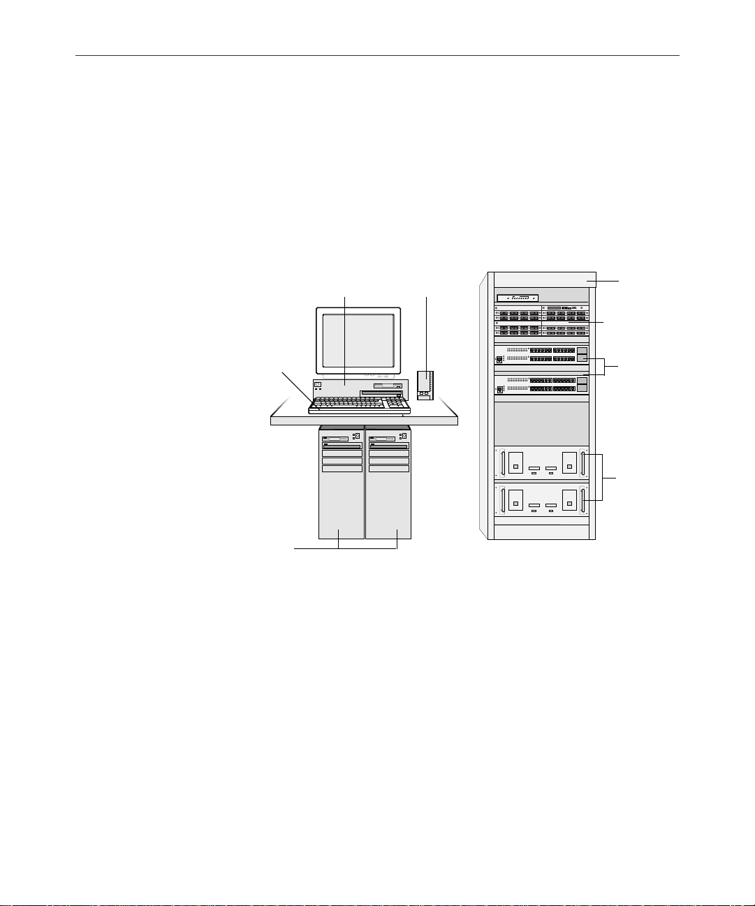
Figure 1-1 shows a close-up of standard NRCS components. Mirrored
NRCS Servers, controlled by the console multiplexor, are the core of
the newsroom computer system. The Ethe rnet™ hub, patch pane l, and
PC-based Peripheral Controller Unit (PC-PCU) are components used
to communicate with the users and devices through the network.
Console multiplexor with
Internal DigiBoard Installed
External Modem
LINK STATUS
Industrystandard
Rack
Patch Panel
Keyboard
Mirrored
NRCS
Servers
Figure 1-1 NRCS Layout
For the latest information on hardware specifications for and features of
n
NRCS can be obtained through the iNews Web site at:
http://www.inewsroom.com/products/ncs/ncs_specs.html.
Customer-Supplied Components
The following sections describe the customer-supplied components
that make up the iNews Newsroom Computer System. Most are hardware components typically purchased from a third party vendor.
Ethernet
Hubs
PC-PCUs (8
Serial Ports
Each)
NRCS Components
Page 24

1-4
NRCS Servers
Console Multiplexor
However, some items can be obtained through iNews. For more information, contact your iNews Sales Representative.
The NRCS Server consists of at least two servers that fully mirror the
database for immediate cut over in the event of a server failure. Adding a third mirrored NRCS Server increases the client-load capacity.
Depending on the server, the number of clients varies.
The NRCS Server stores the database and text created by users at
NRCS W orkstations (clients).
The console multiplexor is typically located in the computer room
near the NRCS Servers and is used by the system administrator to
command and control the servers. The console multiplexor is a
low-end computer that needs only the Microsoft
system (MS-DOS) installed (version 6.22 or higher).
®
disk operating
The customer is responsible for supplying a con sole multiplexor computer for NRCS Servers. The console requires the components specified in Table 1-1.
Table 1-1 Console Multiplexor Requirements
Device Minimum Require ment
CPU 66-MHz, 486 processor
Memory 8 MB of RAM
Hard drive
System Overview and Site Preparation
500-MB IDE ha rd drive
The 500-MB hard drive is more than enough to
n
run DOS and the simple console application.
Page 25

1-5
Table 1-1 Console Multiplexor Requirements (Continued)
Device Minimum Require ment
Diskette drive 3.5-inch diskette drive; reads and writes to
1.44-MB diskettes
®
Operating system MS-DOS
Monitor Compatible monitor
DigiBoard* Required for the mirrored NRCS Server connec-
tions
Software* multiplexor application; runs in DOS
* Supplied by iNews.
Version 6.22
The console cannot be used to run the client software as an NRCS
Workstation. Commands can be sent either to a single server or to all
the mirrored servers at the same time.
Modem
Besides allowing the system administrato r to enter commands to
NRCS Servers, the console multiplexor also displays status and error
messages from NRCS Servers. These messages are recorded in log
files.
The console software, in conjunction with an external modem, allows
the station staff and iNews Customer Support personnel to remotely
control, diagnose, and troubleshoot server and database problems.
The console multiplexor require s an external modem for r emote acce ss
to NRCS Servers. The modem uses an analog telephone line. In addition to the dedicated phone line for the modem, the console operator
or system administrator should also have a telephone situated near the
console so it can be accessed while consulting with iNews Customer
Service personnel.
NRCS Components
Page 26

1-6
Uninterruptible Power Supply
Surge protection and an uninterruptible power supply (UPS) are
essential for NRCS. If the servers lose power even for a moment, the
entire system will stop functioning. There must be one Alternating
Current (AC) connector for each NRCS Server and each PC-PCU
power supply. The circuit must have a dedicated circuit breaker and
an isolated ground.
w
Most systems are designed to work with single-phase (three-wire)
power cord with a grounded neutral conductor. To reduce the risk of
electric shock, always plug the cord into a grounded power outlet.
For best performance, keep all system power connections on the same
power feed distribution panel. Do not connect fans, lamps, coffee pots,
or other equipment to the same outlet that is powering the NRCS
equipment.
Peripheral Controller Unit
The PC-based Peripheral Controller Unit (PC-PCU) is a low-end com-
puter connected between a server and one or more serial devices such
as terminals, printers, and wire services. The PC-PCU relieves the
server of routine communication with the devices.
Each PC-PCU provides up to eight serial device connections.
Ethernet Hub
The Ethernet hub routes data between the clients and the server. Ethernet hubs have multiple, 8-pin, RJ-45 connectors (as shown) that connect all of the network devices.
18
System Overview and Site Preparation
Page 27

1-7
Patch Panel
n
n
RJ-45 cable connectors and jacks are used with Category 5 UTP cables. “RJ”
means Registered Jack and “45” specifies the pin numbering scheme. The connector is attached to the cable, and the jack accommodates the connector. The
RJ-45 is commonly used for a network connection at the wall, the network
interface board in the computer, or the Ethernet hub.
A 10Base-T Ethernet hub is acceptable for NRCS Workstations, but the
100Base-T hub is preferred. The PC-PCU will work only on a 10 Mbs
connection. Typically, status LEDs on the hub show valid connections
or network activity.
A patch panel is used as a junction box where all of the incoming connections from the workstations and network devices are centralized in
the computer room. This is where the incoming connections access the
system. Patch panels allow yo u to reconfigure and diagnose the system with minimal effort; failed computer components can easily be
bypassed.
The system administrator should keep a log of each device connected to the
patch panel.
The customer is responsible for running the cable from the computer
room to the location of each serial device.
Station Network and Workstations
iNews Newsroom Computer Systems are designed to work over
industry-standard Local Area Networks (LAN) and Wide Area Networks (WAN), using standard TCP/IP networking protocols. Workstations and PC-PCUs can operate over routers in a WAN
environment.
n
The system can coexist with other industry-standard protocols, but some
components, such as PC-PCUs, must be isolated from protocols such as IPX
and NetBIOS. Typically, two network cards are installed on the servers and a
separate, closed network for the servers and PC-PCUs is set up.
NRCS Components
Page 28

1-8
Workstations belonging to the newsroom staff (journalists, editors,
assignment managers, and producers) should already be part of the
station’s network. NRCS Workstations require components specified
in Table 1-2.
Table 1-2 Workstation Requirements
Device Minimum Requirement
CPU 200-MHz Pentium with PCI Bus
Memory
32 MB of RAM for Windows 95, 98, and ME
64 MB of RAM for Windows NT and 2000
NRCS v1.4 is approv ed for W indows M E; NRCS
n
v1.3 is not. Windows 95 will no longer be fully
supported for NRCS v1.4.
Hard drive 1-GB enhanced integrated device electronics
(EIDE) hard drive
If Windows NT is the operating system use NTFS
format
Diskette drive 3.5-inch diskette drive; reads and writes to
1.44-MB diskettes
Operating system Windows 95, 98, ME, Windows NT and 2000
Monitor SVGA color monitor (17-inch recommended)
Video board SVGA-compatible video board with 2MB of
VRAM. Must support:
• 1024 x 768 resolution
•256 colors
System Overview and Site Preparation
Page 29
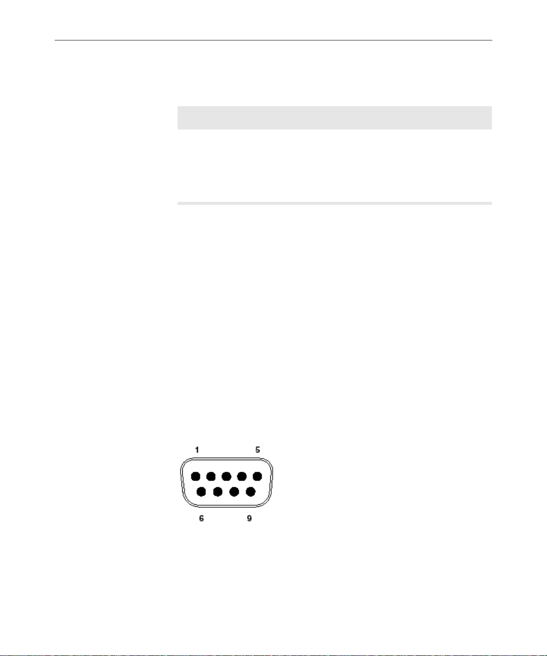
Table 1-2 Workstation Requirements (Continued)
Device Minimum Requirement
1-9
Network board
Once the NRCS server software is running on the network servers,
install the NRCS client software on the staff ’s existing desktop computers to convert them into NRCS Workstations. Additional workstations can be added or removed at anytime, in compliance with
licensing restrictions. Contact your iNews Sales Representative for
more information.
Connectors and Pin Assignments
The following sections provide the industry-standard pin assignments
for connectors that might be used in connecting the iNews Newsroom
Computer System.
9-Pin Serial Connectors
The standard pin configuration for a 9-pin serial connector is shown in
Figure 1-2.
TCP/IP-compatible 10 Mbs network board;
required for network and server connections.
While a 10 Mbs board is the minim um require-
n
ment, a 100Mbs board is recommended.
Figure 1-2 9-Pin Serial Connector
NRCS Components
Page 30
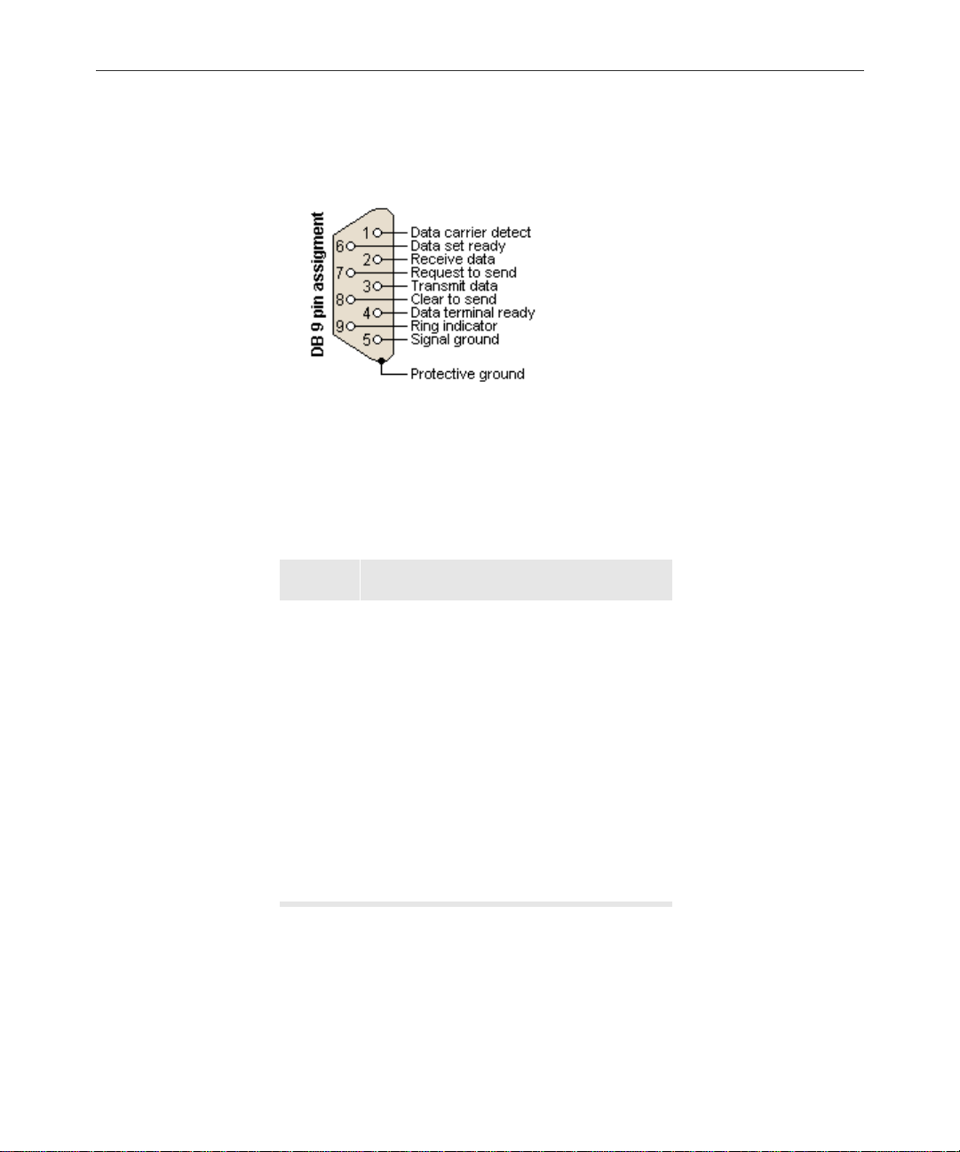
1-10
Figure 1-3 and Table 1-3 show pin assignments for the 9-pin serial connector used with iNews Newsroom Computer Systems.
Figure 1-3 9-Pin Assignment
Not all serial devices use every signal.
Table 1-3 9-Pin Serial Connector Pin Assignments
Pin Signal
1 Data Carrier Detect (DCD)
2 Receive Data (RxD)
3 Transmit Data (TxD)
4 Data Terminal Ready (DTR)
5 Signal Ground (GND)
6 Data Set Ready ( DSR)
7 Request to Send (RTS)
8 Clear to Send (CTS)
9 Ring Indicator (RI)
25-Pin Serial Connectors
The PC-PCU panel provides up to eight serial connectors. The con sole
multiplexor DigiBoard
System Overview and Site Preparation
®
provides four 25-pin serial connectors.
Page 31

1-11
Figure 1-4 shows the serial connector pin outs.
113
14 25
Figure 1-4 25-Pin Serial Connector
Table 1-4 lists the pin assignments for the 25-pin serial connectors on
the PC-PCU and DigiBoard. Not all serial devices use every signal.
Table 1-4 25-Pin Serial Connector Pin Assignments
Pin Signal
n
1GND/Shield
2TxD
3RxD
4RTS
5CTS
6DSR
7GND/Signal
8DCD
20 DTR
22 RI
The remaining pins (9-19, and 21) are not used.
NRCS Components
Page 32

1-12
The connection between the PCU connector and a printer or video terminal requires a DTE serial connection. Figure 1-5 shows a configuration diagram of connection for a printer with a DB25 connector.
n
Transmit data
Receive data
Signal ground
Transmit data
Receive data
Signal ground
The only signals that are required are the Transmit data, Receive data, and
Signal ground. All other signals can be left disconnected.
Transmit data
Receive data
Signal ground
PCU
Printer
Figure 1-5 PCU-to-Printer DB25Cable Configuration
Most printers now have a D B9 conn ector; F igur e 1- 6 show s a PCU con nection for a printer with a DB9 connector.
Transmit data
Receive data
Signal ground
PCU
Printer
Figure 1-6 PCU-to-Printer DB9 Cable Configuration
The connection between the PCU connector and a wire service or
modem is a DCE serial connection. Figure 1-7 shows a straight DCE
connection.
Transmit data
Receive data
Request to send
Clear to send
Data set ready
Signal ground
Data carrier detect
Data terminal ready
2
3
4
5
6
7
8
20
Figure 1-7 PCU-to-Modem Cable Configuration
System Overview and Site Preparation
2
Receive data
Transmit data
3
Clear to send
4
Request to send
5
Data terminal ready
6
Signal ground
7
Data carrier detect
8
Data set ready
20
ModemPCU
Page 33

iNEWS-Supplied Components
DigiBoard
A DigiBoard®, supplied by iNews, must be installed in the console
multiplexor. The DigiBoard provides four 25-pin serial connectors.
• One connector is connected to a modem used for dialing into the
console for remote access and diagnosis.
• Two of the connectors are connected to the mirrored NRCS Serv-
ers.
• The fourth connector is used only if a third mirrored server is
added.
The DigiBoard is shown in Figure 1-8. Detailed cabling configurations
for the DigiBoard serial connectors are provided in the DigiBoard documentation.
DigiBoard
1-13
Serial connectors
Figure 1-8 DigiBoard Layout
NRCS Components
Page 34

1-14
Site Requirements
This section provides details on various site requirements for all
iNews Newsroom Computer Systems. For information on telephone
and networking requirements, see “Modem ” o n pag e 1-5 and “ St ati on
Network and Workstations” on page 1-7.
n
Power Requirements
Space Requirements
It is recommended you install a hand-held, wall-mounted Halon fire extinguisher, or alternative environmentally accep table extinguisher, in the
vicinity of all computer equipment.
Each rack of the iNews Newsroom Computer System requires at least
a 20-ampere, 60-hertz, 110- to 120-volt AC circuit. The circuit must
have a dedicated circuit breaker and an isolated ground. The voltage
between ground and neutral should be less than 1 volt AC; a conduit
ground is unacceptable.
Surge protection and an uninterruptible power supply (UPS) are
essential for all systems. If the computers lose power even for a
moment, the entire system will stop functioning. There must be one
AC connector for each NRCS Server and each PC-PCU power supply.
See “Uninterruptible Power Supply” on page 1-6 for more
information.
Racks typically are 24 inches (61 cm) wide and 30 inches (76.2 cm)
deep. A minimum of 2 feet (.61 m) access clearance is required at the
front, back, and one side of the rack.
Wire and Source Requirements
Customers must provide a feed from all wire service selector boxes to
the computer room. You can provide this with a group run or with
System Overview and Site Preparation
Page 35

individual cables. The wire service selector boxes must not filter out
nonprinting characters such as SOH and ETX. NRCS uses these signals
to recognize the start and end of wire stories.
Printing Requirements
System printers connect to PCUs via RS-232 serial connections. The
system printers must have RS-232 serial ports and accept standard
ASCII text using X-on/X-off protocol.
1-15
n
Workstations can have access to local printers though their network connection, in addition to a direct local connection.
Environmental Requirements
The air conditioning must maintain the operating temperature shown
in Table 1-5. The iNews Newsroom Computer System produces an
estimated heat load of 15,000 BTUs per hour. Table 1-5 shows the
environmental specifications for a standard NRCS environment.
c
The iNews company and staff reserve the right to stop the installation and shut off the iNews equipment if the temperature exceeds
75°F (24°C). Installation will be completed once the air conditionin g
has been corrected.
Table 1-5 Environmental Specifications
Condition Range
Operating temperature 50°F to 75°F (10°C to 24°C)
Storage temperature –4°F to 140°F (–20°C to 60°C)
Relative hum idity 20% to 80%
Altitude 0 to 6000 ft (0 to 1829 m)
Site Requirements
Page 36

1-16
Recommended Tools
To ols may be required when performing the following functions:
• Installing options not a lready installed in systems
• Creating cables
• Troubleshooting
The most common tools and their purposes are:
• Mini tracker—a serial breakout tool for monitoring serial signals
• Ground strap—for releasing static discharge; used when handling
printed circuit boards
• Needle-nose pliers—used to pick up or hold items in tight areas
• Phillips-head screwdriver—Phillips-head screws are typically
used to secure system covers and expansion boards
• Flat-head screwdriver—small flat-head screws are typically used
to secure serial cables
• Cable-making tools—wire cutters and stripper, RJ-45 cable
crimper and spare RJ-45 connectors; used when prefabricated
interface cables are not available
c
System Overview and Site Preparation
Do not leave more than .25-inches of twisted pair cable
exposed—Do not strip jacket more than is necessary. Exposing extra
cable reduces the balanced signal properties.
Page 37

Site Preparation Check List
Use the following check list when preparing for delivery of the equipment. Fill in the blank informatio n as soon as possible.
❑ Ensure that the site meets all the AC power and environmental
requirements. High-volume air conditioning must be provided to
the system and its components.
❑ Arrange for movers and unpackers who are familiar with
unpacking delicate electronic assemblies.
❑ Install all possible cabling before the equipment arrives. For
example, lay out network and interface cables between rooms
before setting up the equipment.
❑ Note all existing network IP addresses at your site. Establish the
IP address range available to the iNews Newsroom Computer
System. IP addresses are supplied by your IS department,
network administrator, or NRCS system administrator.
1-17
Also have your network documentation handy for reference.
❑ Check that any fiber cable cannot be damaged by traffic or
moving objects. T ypically fiber cable is run along duct work. Fiber
cable is made of a fine strand of glass and is not resilient by
nature.
❑ Document a list of installed options; including the type, size, and
number of disk drives.
❑ Verify that the site has a telephone connection to allow a direct
dial-in data line for a modem and a voice telephone line for easy
access to iNews Customer Support (if necessary).
❑ Confirm that the wire services are available. Wire services must be
available when the iNews Newsroom Computer System is
installed. Wire services typically require long lead times.
Site Preparation Check List
Page 38

1-18
❑ Keep all documentation and diskettes together and make them
accessible. If iNews Customer Support needs to walk through
operational steps or reload software, having the documentation
and diskettes easily accessible will improve the process.
❑ Assign a system administrator; also, assign a backup contact
person.
Primary administrator ____________________________________
Secondary administrator __________________________________
Administrators must have access to all user and password infor-
mation.
❑ Note the names and telephone numbers of your iNews Customer
Support representative (in case you need their assistance before,
during, or after installation). Also, note the serial number of the
system and the date it was installed.
Date installed ____________________________________________
Serial number _________________ ___ _________________ ___ __ __
System modem telephone number __________________________
iNews Customer Support representative _____________________
Telephone number 1-800-869-7009 (USA)
Before contacting iNews Customer Support, have ready as much
information as possible about the problem, including any error messages that may have occurred. Also be prepared to provide information listed in the Site Preparation Check List and anything already
tried to resolve the pro blem. Remember to r ecor d the support person’s
name and telephone number in the event that a call-back is necessary.
Call-back contact _________________________________________
Telephone number ________________________________________
System Overview and Site Preparation
Page 39

CHAPTER 2
Installing Hardware
This chapter explains the setup of the Newsroom Computer Systems.
Information includes using an Uninterruptible Power Supply (UPS)
with all systems. It includes installin g the UPS, DigiBoard, serial connections to the console multiplexor, and network connections. It contains the following major sections:
• Connecting t he UPS
• Setting up the Console Multiplexor
- DigiBoard Configuration for Console
- Installing the Console Applicati on
• Configuring the NRCS Servers
• Setting up a PC-PCU
- Network Card Installation and Setup
- DigiBoard Configuration for PC-PCU
- Installing the PC-PCU Application
- PCU Kit Boot Up
- PC-PCU Kit Installation Checkl ist
Page 40

2-2
s
Connecting the UPS
NRCS requires a UPS to protect against power failures. Each NRCS
Server must have its own UPS. The console multiplexor and PC-PCUs
can share a UPS with a mirrored NRCS Server.
Ensure the UPS has surge protection and a high enough rating to handle all systems connected to it. The rating plate on each system will
help calculate the required rating for th e UPS. Figure 2-1 shows how to
connect multiple systems to a UPS using a pow er strip.
UPS
Figure 2-1 UPS Connections
Setting up the Console Multiplexor
Typically, sites will have their NRCS Servers and console multiplexor
configured by iNews technicians at the iNews facility. Occasionally,
this integration is done on site—again, typically by iNews technicians.
However, in a few cases, this may be done by a site’s Information Systems’ staff; therefore, this section is provided to give basic procedures
for setting up the console multiplexor, including installing the digiboard.
Grounded AC wall outlet
Power strip
One NRCS Server,
console multiplexor, and
PC-PCU power connection
Installing Hardware
Page 41

2-3
Unpack and set up the computer that will serve as the console multi-
plexor according to the manufacturer’s instructions. After setting up
the computer, power on the system and install MS-DOS according to
Microsoft’s instructions.
n
Power on the console multiplexor computer before installing the DigiBoard.
This lets you know if the computer is working before opening it. Remember to
power off the system before installing any hard ware.
After you have set up the console multiplexor computer, connected
the monitor, and loaded MS-DOS, install the DigiBoard and the console multiplexor software according the following se ctions.
DigiBoard Configuration for Console
The DigiBoard provided by iNews for the
console multiple xor is
the PC/4 m o del.
Configuring the DigiBoard
The DigiBoard is an expansion board that plugs into an industry standard architecture (ISA) slot on the computer’s system board.
This section provides a generic installation procedure. DigiBoard’s
documentation provides installa tion instructions, configuration settings, and cabling diagrams. Before installing the DigiBoard into the
console multiplexor, set the board’s configuration switches.
To configure the DigiBoard, do the following:
1. Put on a wrist strap and attach the ground clip to the computer’s
chassis.
Setting up the Console Multiplexor
Page 42

2-4
c
Semiconductor devices are vulnerable to damage by electrostatic
discharge (ESD). Always use an ESD wrist strap or other grounding
device when opening the computer or removing any circuit boards
from its packing.
Figure 2-2 ESD Wrist Strap
2. Remove the DigiBoard from its static-proof bag. Hold the board by
its outer edges to avoid touching the components and connector
on the board.
Installing Hardware
Switches
Figure 2-3 DigiBoard
3. Configure the switches and jumpers according to the following
settings:
Page 43

2-5
See the documentation
that is suppl ied with
your DigiBoard to identify the switches and
jumpers.
You must set the five banks of dip switches as shown in
Ta ble 2-1—these are not the factory settings.
Table 2-1 DigiBoard Switch Settings
Switch SW–1 SW–2 SW–3 SW–4 SW–5 SW–6 SW–7 SW–8 SW–9 SW –10
DS1OnOnOnOnOnOnOnOnOnOff
DS2 Off On Off Off On On On On NA NA
DS3 Off On Off Off On On Off On NA NA
DS4 Off On Off Off On Off On On NA NA
DS5 Off On Off Off On Off Off On NA NA
Ensure that all jumpers are set according to Table 2-2. Typically,
these jumpers are set this way at the factory, but you should confirm these settings.
Table 2-2 DigiBoard Jumper Settings
Jumper Setting
J1 Jumper on pins 1–2
J2 Jumper on pins 1–2
J3 Jumper on pins 1–2
J4 Jumper on pins 1–2
J9 Jumper on pins 2–3
J10 Jumper on pins 2–3
J85 Jumpered
J89 Jumpered
Setting up the Console Multiplexor
Page 44

2-6
J5 through J8 do not
have pins on the PC/4
DigiBoard model.
Installing the DigiBoard
After the DigiBoard’s switches and jumpers have been configured, use
the following instructions in conjunction with the documentation provided with the system.
To install the DigiBoard, do the following:
On J1 through J10, the jumpers should appear on the pins as
shown:
On J85 through J90, the jumpers should appear as shown:
n
Installing Hardware
1. Turn off the computer.
2. Remove the computer’s cover according to the manufacturer’s
instructions, supplied with the computer. Remember to always
use an ESD wrist strap (as shown in Figure 2-2 on page 2-4) or
other grounding device when opening the computer or removing
any circuit boards from its packing.
Label all cables you disconnect. Note the position and location in which the
cables are installed.
Page 45

3. Remove the expansion slot cover from within the computer.
Slot cover screw
2-7
ISA connectors
(larger)
PCI connectors
(smaller)
Slot cover
4. Align the connector on the DigiBoard with the system board ISA
connector.
Screw
Board
5. Press the board firmly until the connector is seated. Do not force
the board. If you meet with a lot of resistance, pull it out, inspect
the connector, and try again.
Setting up the Console Multiplexor
Page 46

2-8
6. Reinstall the screw used for the slot cover to secure the DigiBoard.
7. Reconnect any cables that you disconnected.
8. Replace the console multiplexor cover.
Cabling the NRCS Servers to the Console
This section describes how to connect the NRCS Servers to the console
multiplexor computer. This should only be done after all optional
hardware has been installed and the operating system and the NRCS
software has been loaded into all systems.
The DigiBoard comes with the serial cable shown in Figure 2-4. Use
this cable to connect the mirrored NRCS Servers and an external
modem to the console multiplexor. One end of this cable has a 78-pin
connector. The other end provides four DB-25 serial connectors.
78-pin connector
Because all Dig ib oard
ports are DTE, a crossed
connector is required on
one end when conn e ct ing to a computer or file
server. Use straight connectors on both ends for
connecting to a modem.
n
Installing Hardware
Four 25-pin male connectors
(labeled P1 through P4)
Figure 2-4 DigiBoard Connector Cable
The connection between the console multiplexor cable and the NRCS
Servers requires a Data Terminal Equipment (DTE) serial connection.
Figure 2-5 shows a configuration diagram of the connection. The DigiBoard documentation provides additional configuration diagrams.
The only signals that are required are the Transmit data, Receive data, and
Signal ground. All other signals can be left disconnected.
Page 47

2-9
DigiBoard cable connector
Transmit data
Receive data
Request to send
Clear to send
Data set ready
Signal ground
Data carrier detect
Data terminal ready
Server serial port
1
2
3
4
5
6
7
8
20
Receive data
2
Transmit data
3
Clear to send
8
Request to send
7
Data terminal ready
4
Signal Ground
5
Data set ready
6
Ring indicator
9
Figure 2-5 DigiBoard-to-Server Cable Configuration
The serial connection described in the following procedure assumes
that a 9-pin-to-RJ-45 adapter is used on the server end and a
25-pin-to-RJ-45 adapter is used on the DigiBoard console cable. Category-5 cables with RJ-45 jacks connect the servers to the console.
To connect the console cable to the servers, do the following:
1. Connect the 78-pin end of the cable connects to the DigiBoard
installed in the console multiplexor.
78-pin connector
2. Secure the connection with the two screws attached to the cable.
3. Connect the mirrored servers to the DigiBoard using
9-pin-to-RJ-45 adapters and 25-pin-to-RJ-45 adapters. The RJ-45
connection is made with a category-5 cable.
Setting up the Console Multiplexor
Page 48

2-10
n
Modem connector (P4)
DigiBoard console
multiplexor cable
Optional 9-pin-to-RJ-45 adapters and 25-pin-to-RJ-45 adapters are available
through iNews.
a. Connect a 9-pin-to-RJ-45 adapter to serial port 1 of each mir-
rored server.
b. Connect a 25-pin-to-RJ -45 adapter to the DigiBoar d connect ors
labeled P1 and P2.
c. Connect server A to DigiBoard connector P1, and server B to
DigiBoard connector P2, using category-5 cables with RJ-45
jacks.
Category-5 cables
Serial port 1
P1
P2
9-pin to RJ-45
adapters
25-pin-to-RJ-45
adapters
n
The serial cable length betwee n th e systems should not exceed 100 feet. Serial
cables that exceed 100-feet long may cause communication errors.
Cabling the Modem to the Console
The external modem allows the station staff and iNews Customer Support personnel to remotely control, diagnose, and troubleshoot server
and database problems.
Installing Hardware
NRCS Server A NRCS Server B
Page 49

2-11
Connect the external modem into the P4 connector of the DigiBoard
console multiplexor cable. The P4 connector is a DB-25 serial connection. The modem must also plug into an analog telephone line.
n
Transmit data
Receive data
Request to send
Clear to send
Data set ready
Signal ground
Data carrier detect
Data terminal ready
If the site happens to have four NRCS Servers, all four connectors on the
DigiBoard cable are used by the servers. Connect the external modem into the
serial port of the console multiplexor. To use a modem with a mux, it must be
attached to one of the four Digiboard ports or another external ser vice port.
An internal modem will not work.
The connection is a Data Communication Equipment (DCE) serial connection. A DCE is a straight connection between the connectors.
2
3
4
5
6
7
8
20
2
Receive data
Transmit data
3
Clear to send
4
Request to send
5
Data terminal ready
6
Signal ground
7
Data carrier detect
8
Data set ready
20
ModemDigiBoard cable
Figure 2-6 DigiBoard-to-Modem Cable Configuration
The modem is configured through the console multiplexor software,
using the configuration file (a text file called console.cfg). Instruc-
tions are provided in “The Remote Console” in Chapter 2 of the Newsroom Computer System Operations Manual.
Set up the modem for:
• Auto-answer
• Fixed serial port speed of 9600 baud
• 8 bits, no parity, 1 stop bit
• X-on/X-off flow control
• No answer-mode messages displayed
Setting up the Console Multiplexor
Page 50

2-12
• No command echo
Installing the Console Application
The console multiplexor application is a DOS program; it does not run
on Windows-based operating systems. Install the console multiplexor
software according to the following procedure:
1. Place the console working floppy disk in the A drive of the console
multiplexor computer.
2. Type the following DOS command:
C:\>xcopy a:*.* c:\console /s/e
3. After pressing Enter, you will see a message verifying whether
console specifies a file name or directory name.
Type d for directory. This will create a Console directory on the C
drive into which all the necessary files will be copied. Here’s an
example of how the display may appear:
Installing Hardware
C:\>xcopy a:*.* c:\console /s/e
Does console specify a file name
or directory name on the target
(F = file, D = directory)? d
Reading source file(s)...
The console software is now installed.
Page 51

Modifying the Console Configuration File
You may need to modify the console configuration file
(console.cfg) so it is set up for your system’s specific configuration.
The console configuration file (as shown in Figure 2-7 on page 2-14)
contains numerous keywords, most of which are followed by parameters, such as hostess and irq values.
Keywords are grouped in sections according to ports used by certain
machines connected to the console, such as each server and external
modem.
2-13
n
The hostess and irq values for each port should not be changed. The modem
section has five keywords, three of which may be mo dified—the port used
dictates the hostess value, the password should be changed, and timeout is
typically set to five minutes.
For more information on these keywords and how to edit the file, see
“The Console Configuration File (console.cfg)” in Chapter 2 of the
Newsroom Computer System Operations Manual.
Setting up the Console Multiplexor
Page 52

2-14
Port 3 is unused in this
example. Servers A and
B are configured on
ports 1 and 2 respectively. The modem is
configured on port 4.
Here is an example of a typical console.cfg file:
log c:log *65528
computer
hostess 2c0
irq 3
label NRCS
name a
speed 9600
;
computer
hostess 2c8
irq 3
label NRCS
name b
speed 9600
;
modem
speed 9600
hostess 2d8
irq 3
password changeme
timeout 5:00
Figure 2-7 Sample Console Configuration File (console.cfg)
Modifying the Autoexecutable Batch file
After installing the console software, two lines should be added to the
autoexecutable batch file (autoexec.bat) that runs when the console
multiplexor computer boots. The lines are:
cd\console
console
These lines cause the console program to e xecute each time the console
multiplexor computer is rebooted.
Installing Hardware
Page 53

You can start the program manually by typing console while in the
console directory. If the program exits with an error, there is a mistake
in console.cfg. The error message usually contains a reference to a
line number that will guide you to locate the mistake.
Configuring the NRCS Servers
When NRCS Servers are purchased through iNews, all hardware is
installed, drives are partitioned, and operating systems are loaded.
The installation of the NRCS Server software is usually done by iNews
technicians either at the iNews facility or on site.
Temporary Monitor and Keyboard Connections
Initially, a keyboard and monitor is attached to the NRCS Servers to
configure the servers and install the operating system and NRCS software. The mirrored servers are configured one at a time.
2-15
n
The iNews-recommended servers come with a personal system
®
(PS)/2
graphics array (VGA)-compatible monitor connector. Although the
servers do not automatically come with a monitor, this industrystandard monitor should be available at the site. Both the keyboard
and monitor connections are keyed to fit in only the correct position on
the rear of the servers. Follow the documentation provided by the
manufacturer when connecting the keyboard and monitor.
After the software is loaded and servers configure d, the ke yboard and
monitor can be removed and the servers can then be controlled from
the console multiplex or.
Systems are processed in pairs. The two servers of a dual system are referred
to as “server A” and “server B.” Label the servers A and B.
- compatible keyboard. These servers also provide a video
Configuring the NRCS Servers
Page 54

2-16
Reminders for Setting Up Servers
Remember when setting up the NRCS Servers:
• Inspect the server and software against the packing list and purchase specification. Look for peripheral discrepancies (for example, SCSI devices or network boards).
• NRCS Servers need to be installed near the console multiplexor.
• The NRCS Server software and database must be loaded according to specifications in this manual.
• If an existing version of Avid NetStation is installed, NRCS software must be loaded according to upgrade specifications in this
manual.
• The NRCS Servers may require some preparation prior to installing the operating system, NRCS software, and the database. Install
any optional hardware according to the manufacturer’s documentation.
• Once the NRCS Server hardware is completely installed, continue
on to the following sections to get the servers connected to the network.
Connecting NRCS Servers to the Network
The NRCS Servers can connect to either a 10Base-T or 100Base-T
Ethernet hub. The network connection described in the following procedure assumes that the site network uses category-5 cables with RJ-45
jacks.
Older network connections use BNC connectors. If using BNC connections, cable the servers as described in the following procedure, replacing the connections with BNC connectors.
The iNews-recommended servers have two installed network boards.
The second network board in the servers connect to a dedicated
10Base-T Ethernet hub. This Ethernet hub handles just the network
traffic between the PCUs and NRCS Servers.
Installing Hardware
Page 55

Customer network
connection
2-17
To connect the NRCS Servers to the network, do the following:
1. Connect a category-5 cable with RJ-45 jacks into the first network
board on each NRCS Server.
2. Connect the other end of the category-5 cable into available RJ-45
jacks on a dedicated server/PCU 10Base-T Ethernet hub.
3. Connect a category-5 cable with an RJ-45 jack into the second network board on each NRCS Server.
4. Connect the other end of the category-5 cable into an available
RJ-45 jack on the LAN Ethernet hub.
Ethernet hub used for mirrored servers and PC-PCUs
Network boards
Ethernet hub
Setting up a PC-PCU
In keeping with iNews’ continuing efforts toward open architecture, a
PC-PCU Installation kit was developed to replace the proprietary
rack-mounted PCU IIIa and IVa. The iNews Newsroom Computer
System uses PC-based Peripheral Controller Units (PC-PCUs) to
NRCS Server A
NRCS Server B
Setting up a PC-PCU
Page 56

2-18
control serial devices of several types, as described in the Newsroom
Computer System Operations Manual. The PC-PCU kit includes:
• An industry-standard multiport serial card (such as the PC/X
DigiBoard)
•Software
• Installation instructions
Customers wanting
rack-mount installations may purchase
rack-mount ISA b u s
PCs from thi rd-party
vendors.
In combination with a customer-supplied computer and network card,
the PC-PCU kit produces a 4- or 8-port PCU on any standard 386 (or
faster processor) ISA bus PC, running DOS (or Windows® 98 booted
to DOS mode) with at least 1MB RAM. DOS 6.22 is recommended,
although earlier versions will work.
The PC-PCU kit uses a public domain TCP/IP networking package
and is compatible with any Network Interface Card (NIC) for which a
packet driver has been written. The Crynwr packet drivers
(pktd11.zip) are public domain and available for a large number of
NICs. A copy of these public domain packet drivers is included in the
pktdrvr directory on the installation floppy disk, supplied by iNews.
They can also be downloaded from various sources on the Internet,
such as:
ftp://ftp.crynwr.com/drivers
ftp://ftp.cdrom.com/pub/simtelnet/msdos/pktdrvr/
http://oak.oakland.edu/simtel.net/msdos/pktdrvr-pre.html
http://www.jumbo.com/pages/utilities/dos/pktdrvr/
Network card manufacturers may also have packet drivers available
on their Internet sites or included with their driver diskettes. For info rmation on qualified network cards and instructions for installing
them, see “Network Card Installation and Setup” on page 2-19. Other
information about the PC-PCU ki t is available in Appendix A. A helpful PC-PCU kit installation checklist is also available on page 2 -30.
Installing Hardware
Page 57

Pre-Installation PC Setup
For initia l ins tal lat ion an d se tup, the PC need s to have a VGA mon ito r
and keyboard attached. After installation, configuration, and testing,
the monitor and keyboard can be removed and the unit run “headless.” Some PCs may require the keyboard to be connected in order to
boot.
The PC must already have an operating system installed and be able to
boot up. While Windows 95 and Windows 98 operating systems will
work, DOS is preferred.
The installer must know the location of the operating system directory.
For instance, DOS is installed in a \ DOS directory, Windows 95 may
be found in a \WINDOWS or \WIN95 directory, depending on th e
installation. The PC-PCU kit software is designed to run off the C:
drive.
The multiport serial I/O card is typically installed at IRQ 3 with a base
I/O address of 280h. Since this setting may conflict with a factoryinstalled COM2 port, the installer should go into the PC’s CMOS setup
routine and disable COM2. Consult the PC manufacturer’s
documentation for instructions on entering setup and how to disable
the COM2 port. If a COM4 port is present on the PC, it should also be
disabled in setup.
2-19
COM1 should not be disabled; it can be used to obtain diagnostic messages from the PC-PCU as it boots and is restarted. This is not
required.
Network Card Installation and Setup
This section gives an overview of the installatio n a nd con figuration
process for the network cards. Please consult the network card manufacturer’s documentation for further details and updated instructions.
Setting up a PC-PCU
Page 58

2-20
While any network card that has a packet driver can be used, the
PC-PCU kit installation batch file only supports the following cards:
• Intel EtherExpress Pro/10+
• 3Com 3C503
• 3Com 3C509
The installer should note the Ethernet address of the network card
since the card’s physical address must be entered into configuration
files on the NRCS Servers later in the setup. The card’s address is usually printed on the card itself. Consult your netwo r k card documentation for details on how to determine the Ethernet address of your card.
The network card must be configured to operate at IRQ 5 with a base
I/O address of 300h to work with the installation routine. The general
sequence is as follows:
1. Turn off the PC
2. Using proper electrostatic discharge (ESD) procedures, install the
card in the PC according to manufacturer’s instructions
n
Installing Hardware
3. Boot the computer to a regular DOS prompt:
When you see the Starting MS-DOS or Starting Windows
prompt, press the F5 key to bypass the normal startup files
4. Run the manufacturer’s card setup utility on the driver diskette
that came with the card:
A:SOFTSET2 Intel EtherExpress Pro/10+
A:MENU 3Com 3C503 and 3C509
5. Set the IRQ to 5 and the I/O address to 300h.
Some devices that may conflict with these IRQ and I/O address settings
include sound cards and CD-ROM drives. For this reason, a PC without a
sound card or CD-ROM may be easier to install and configure.
Page 59

DigiBoard Configuration for PC-PCU
The iNews PC-PCU Installation kit includes a PC/4 or a PC/8 DigiBoard. Multiport serial boards from other manufacturers can also be
used as noted in the instruction in “Other Brands of Serial Boards” on
page A-10.
Before the DigiBoard is installed into the PC, it must be configured
with settings appropriate for PCU operations because the card uses
IRQ 3 with serial ports (P1 through P4 or P8) starting at I/O address
280h. These settings vary, depending on whether the DigiBoard is a
PC/4 or PC/8 model. For steps on how to install the DigiBoard into a
PC, see “Installing the DigiBoard” on page 2-6.
PC/4 DigiBoard
Va rious dip switches and jumpers must be set on the DigiBoard
according to the following:
2-21
See the documentation
that is suppl ied with
your DigiBoard to identify the switches and
jumpers.
You must set the five banks of dip switches as shown in
Ta ble 2-3—these are not the factory settings.
Table 2-3 DigiBoard Switch Settings for PC-PCUs
Switch SW–1 SW–2 SW–3 SW–4 SW–5 SW–6 SW–7 SW–8 SW–9 SW–10 I/O
DS1 Off On Off On Off On On On On On 2a0h
DS2 OffOnOffOnOnOnOnOnNANA280h
DS3 Off On Off On On On Off On NA NA 288h
DS4 Off On Off On On Off On On NA NA 290h
DS5 Off On Off On On Off Off On NA NA 298h
Setting up a PC-PCU
Page 60

2-22
The dip switch rockers are in the off position when they are pushed
down towards the bottom of the card.
Ensure that all jumpers are set according to Table 2-4. Typically, these
jumpers are set this way at the factory, but you should confirm these
settings.
Table 2-4 DigiBoard Jumper Settings for PC-PCUs
Jumper Setting
P2 and P4 Jumper middle pins
J1 Jumper on pins 1–2
J2 Jumper on pins 1–2
J3 Jumper on pins 1–2
J4 Jumper on pins 1–2
J9 Jumper on pins 2–3
Installing Hardware
J10 Jumper on pins 2–3
J85 Jumpered
P2 and P4 connectors, located at the top edge of the board, have four
pins each. The middle two pins on each connector should be
jumpered, as shown:
Page 61

2-23
J5 through J8 do not
have pins on the PC/4
DigiBoard model.
PC/8 DigiBoard
See the documentation
that is suppl ied with
your DigiBoard to identify the switches and
jumpers.
On J1 through J10, the jumpers should appear on the pins as shown:
On J85 through J90, the jumpers should appear as shown:
After the DigiBoard is configured, install the card in the PC according
to the procedures in “Installing the DigiBoard” on page 2-6.
You must set the nine banks of dip switches as shown in
Ta ble 2-5—these are not the factory settings.
Table 2-5 DigiBoard Switch Settings for PC-PCUs
Switch SW–1 SW–2 SW–3 SW–4 SW–5 SW–6 SW–7 SW–8 SW–9 SW–10 I/O
DS1 Off On Off Off On On On On On On 2c0h
DS2 OffOnOffOnOnOnOnOnNANA280h
DS3 Off On Off On On On Off On NA NA 288h
DS4 Off On Off On On Off On On NA NA 290h
DS5 Off On Off On On Off Off On NA NA 298h
Setting up a PC-PCU
Page 62

2-24
Table 2-5 DigiBoard Switch Settings for PC-PCUs (Continued)
Switch SW–1 SW–2 SW–3 SW–4 SW–5 SW–6 SW–7 SW–8 SW–9 SW–10 I/O
DS6 Off On Off On Off On On On NA NA 2a0h
DS7 Off On Off On Off On Off On NA NA 2a8h
DS8 Off On Off On Off Off On On NA NA 2b0h
DS9 Off On Off On Off Off Off On NA NA 2b8h
The dip switch rockers are in the off position when they are pushed
down towards the bottom of the card.
Ensure that all jumpers are set according to Table 2-6. Typically, these
jumpers are set this way at the factory, but you should confirm these
settings.
Table 2-6 DigiBoard Jumper Settings for PC-PCUs
Installing Hardware
Jumper Setting
P2 and P4 Jumper middle pins
J1 through J8 Jumper on pins 1–2
J9 Jumper on pins 2–3
J10 Jumper on pins 2–3
J85 Jumpered
Page 63

2-25
P2 and P4 connectors, located at the top edge of the board, have four
pins each. The middle two pins on each connector should be
jumpered, as shown:
On J1 through J10, the jumpers should appear on the pins as shown:
On J85 through J90, the jumpers should appear as shown:
After the DigiBoard is configured, install the card in the PC according
to the procedures in “Installing the DigiBoard” on page 2-6. Attach the
8-port DB-25 connector box to the back of the DigiBoard in the PC.
Installing the PC-PCU Application
After the network and multiport serial cards are configured and
installed, you can install the PCU software by doing the following:
1. Boot the PC.
2. Insert the PCU Installation floppy disk, supplied by iNews, in the
A drive on the computer.
Setting up a PC-PCU
Page 64

2-26
3. Run the install.bat file, using the following format:
A:INSTALL <OS directory> <network card> <port#>
Parameter Acceptable Options Explanation
c
Operating System
Directory
Network Card INTEL
Number of Ports 4
Selecting an improper operating system (OS) during installation
may result in system files being overwritten and a PC that will not
boot.
The installation batch file makes the following assumptions:
• The PC’s OS is in either the \dos, \windows, or \win95
directory.
• The network card is configured at IRQ 5 with a base I/O
address of 300h.
• The multiport serial card is configured at IRQ 3 with the first
port set to a base I/O address of 280h.
DOS
WINDOWS
WIN95
3C509
3C503
8
DOS 6.22 location
Windows 95 location
Windows 95 location
Intel EtherExpress Pro/10+
3Com 3C509
3Com 3C503
PC/4 DigiBoard
PC/8 DigiBoard
n
Installing Hardware
If any of these assumptions are not accurate for your PC, you will need to
install the PCU files and then manually configure the config.sys and/or
autoexec.bat files on the PC as outlined in this manual’s appendix, containing
packet driver data.
The procedure for running the install command will vary depending on the operating system.
Page 65

2-27
DOS Computers
DOS and Windows 3.1
Windows 95
For computers that boot to a DOS prompt, the command appears:
C:\A:INSTALL DOS 3C509 8
Press Enter.
For computers that boot to Windows 3.1, exit Windows by clicking
File, then Exit in Program Manager (ALT-F4). After the DOS
prompt appears, the command is the same as that shown for DOS
computers.
For computers that boot to Window s 95, click the Start button and
select Run. In the Run dialog box, type the appropriate command,
such as:
A:\> INSTALL WINDOWS INTEL 8
Press Enter or click OK.
After the installation, the PC will automatically be in DOS mode when
it is rebooted.
For usage instructions for the install.bat file, use either of the following
commands:
A:INSTALL HELP or A: INSTALL ?
To install the PCU files without modifying the PC’s startup files, use
the following command:
A:INSTALL FILES
NRCS Server Configuration for PC-PCUs
Software configuration of a PC-PCU kit on the NRCS Servers is the
same as configuring the standard rack-mount PCU IIIa or IVa. Entries
for the PCU must be found in the /etc/hosts ,/ect/bootptab and
/site/config. For more information on adding a PCU to your system and configuring the software, see Chapter 11 and Appendix D of
the Newsroom Computer System Operations Manual. Examples of the
entries for PCUs are provided in that manual as well as Appendix A of
this manual.
Setting up a PC-PCU
Page 66

2-28
Additionally, the pcuos.exe file must be installed on the server. Use
the following command to determine whether the file exists on the
server:
NRCS-A: ls -l ccu/at/pcuos.exe
If the file exists, a message similar to the following will appear:
-rw-r--r-- 1 so newssys 97837 Apr 30 17:38 ccu/at/
pcuos.exe
The example is of a
message displayed on
an SGI system.
PCU Kit Boot Up
If the file does not exists, a message similar to the following will
appear:
Cannot access ccu/at/pcuos.exe. No such file or
directory.
If it does not exist on the server, contact iNews Customer Support during normal business hours for assistance in obtaining the program file.
Rack-mount PCU IIIa and IVa models have red LED displays that indicate boot status. The PC-PCU kit does not have this same status display; however, the status display can be noted on the VGA monitor.
When the PC-PCU is booted up, it will broadcast its network card
address. The following will be seen on the monitor after the con-
fig.sys files loads the pcuboot.exe:
My Ethernet address is 00:20:AF:9F:DD:A5
LEDS 08000
At this point, the PC-PCU has broadcast its bootp request, it is on the
network, and the NRCS Server is properly configured to respond to
Installing Hardware
Page 67

2-29
the request. The PC-PCU will obtain its IP address and the following
will display on the monitor.
ethernet address: 00 20 AF 9F DD A5
internet address: 125.1.10.30
LEDS 00000
If the PCU is restarted at the console, a message similar to the following will be displayed as it restarts:
LEDS 08101
LEDS 08102
LEDS 00030
The final LED display indicates the PC-PCUs number.
This information is also displayed on the COM1 serial port of the PC.
If a terminal or computer running a communications program at
9600-8n is hooked up to the COM1 port, the status of the PC-PCU can
be monitored. It may be handy to have a long enough cable on hand so
the PCU’s COM1 port can be temporarily plugged into the console PC
for troubleshooting.
After the PC-PCU is properly configured an d can be restarted f rom the
console, it is no longer necessary to have the VGA monitor and keyboard attached; they can be removed. However, before removing, it
may be necessary to go into the CMOS setup of the PC to adj ust its
boot-up behavior. Some PCs will not boot without a keyboard. They
will issue a keyboard error during the Power On Self Test (POST) and
halt. It may be possible to change a setting in the CM OS setup to have
the PC ignore keyboard errors during POST, which will allow it to
boot without an attached keyboard. Consult your PCs manufacturer’s
documentation for instructions on these features and their disablement procedures.
Setting up a PC-PCU
Page 68

2-30
PC-PCU Kit Installation Checklist
Item Y Option
1. The PC has DOS or Windows 95 operating
system loaded and boots up.
2. COM2 and COM4 have been disabled on the
PC.
3. The operating system is: __________________
4. The operating system is located in the
following directory:
5. The network card is (Intel, 3C503, or 3C509): b _________________
6. The network card’s Ethernet address is: _____________________
7. The network card is configured at Interrupt 5
with a base I/O address of 300h.
8. The DigiBoard has been jumpered as
described.
9. The DigiBoard has the following number of
ports (4 or 8):
10. The install.bat installation routine has
been run.
c
c
a _________________
c
c
c _________________
c
Installing Hardware
11. The PC-PCU is entered in /etc/bootptab
and /site/config.
12. The PC-PCU is attached to the network. c
13. The LED dis p lay on the monitor goe s t o 00000
after it boots up.
14. The PC-PCU restarts at th e console and gives
“Hot-to-go” messages.
c
c
c
Page 69

2-31
Item Y Option
The following steps are optional.
15. The PC-PCU boots properly without an
attached keyboard.
16. The keyboard has been removed. c
c
Setting up a PC-PCU
Page 70

2-32
Installing Hardware
Page 71

SECTION II
Software Installation & Upgrades
This section provides detailed procedures for installing
the iNews Newsroom Computer System (NRCS) at new sites,
or upgrading client and server software at sites with existing
NRCS Servers. The section consists of the following chapters:
• Chapter 3, New SCO/SGI Installation
• Chapter 4, NRCS Client Installation
• Chapter 5, Upgrades on Existing Servers
Page 72

Page 73

CHAPTER 3
New SCO/SGI Installation
This chapter introduces you to installation procedures for the NRCS
Server software on new servers. These procedures are written for new
sites only.
c
Installation procedures in this chapter destroys any previously
loaded version of NetStation, AvidNews, and associated NRCS databases. If you have an existing version of these newsroom computer
systems, you must use upgrade procedures to install NRCS. If you
are upgrading a site with NRCS Server software on existing servers,
refer to procedures in Chapter 5. If you are upgrading a site on new
servers, contact iNews Customer Support for assistance.
This chapter contains the following major sections:
• Assumptions
- Before You Begin the Installation Procedure
• Installing NRCS at New Site
- Upgrade Summary
- Upgrade Details
• Installation Verification Checklist
- Functions to Test from NRCS Workstations and VT Terminals
- Functions to Test from the Console
Page 74

3-2
Assumptions
This chapter assumes:
• You checked the hardware configuration and all devices are supported by your UNIX operating system.
• NRCS is being configured as a dual (AB) system of servers. Contact iNews Customer Support to discuss procedures for a triple
(ABC) system.
The console multiplexor
is referred to as the
“console” in this manual.
For NRCS v1.3, use
SCO Open Server
Enterprise Release 5.0. 5
or SGI Irix 6.5.3.
• The system is connected to a console multiplexor, to which iNews
Customer Support personnel has dial in access.
• The appropriate UNIX operating system has been installed on all
host computers that will run NRCS v1.4:
- For SCO, you need SCO Open Server Enterprise Release 5.0.5
or 5.0.6, patched according to SCO’s recommendations.
- For SGI, you need Irix 6.5.3 or 6.5.9.
Depending on your operating system, you can f ind the version
using one of the two uname commands below:
SCO_A: uname -X
System = SCO_SV
Node = a2sco
Release = 3.2v5.0.5
KernelID = 97/09/03
Machine = Pentium
BusType = ISA
Serial = 2DL084198
Users = 5-user
OEM# = 0
Origin# = 1
NumCPU = 1
SCO_A:
New SCO/SGI Installation
Page 75

3-3
-OR-
SGI_A: uname -R
6.5 6.5.3
SGI_A:
• You have enough space on the server hard drive; you need 50 MB
for the NRCS software.
m
n
c
You can get a report on the available disk space in the root partition with the
df
UNIX
report is available on SCO with the
• The person performing the installation has attended an NRCS,
• Correct disk(s) partitions for the NRCS database have already
NRCS v1.3 installation process will be aborted if the correct partitions do not exist.
command. The results ar e gi ven in 5 12k blocks . A mor e descr iptive
df -v
command.
AvidNews, or NetStation system administration course or has
equivalent experience. This includes having a working knowledge
of ed, the UNIX line editor.
been installed. This applies to both SCO and SGI systems.
You are familiar with SGI’s disk partitioning scheme, understand
SGI disk naming conventions and could identify the database
partition in a prtvtoc -a display (usually dks0d2s7 on the O2
platform).
Before You Begin the Installation Procedure
Before you begin installing NRCS:
• Read all Release Notes (provided on the NRCS installation CD) to
get the most up-to-date product and installation information.
• Familiarize yourself with the entire installation procedure.
• Create a list of Ethernet or Internet addr esses of any PCs to be con-
figured on this system.
Assumptions
Page 76

3-4
• Ensure the following items are available:
- NRCS installation CD.
- Installation tapes or CDs for other products being installed
with the iNews Newsroom Computer System.
- For SCO systems, two blank tapes and three double-sided,
high-density diskettes for each host computer (server) on the
iNews network.
- For SGI systems, three blank tapes for each host computer
(server) on the iNews network.
c
The iNews Newsroom
Computer System was
formerly known as
Avstar NRCS.
You will need a license key to i nstal l the NRCS ser ver software. You
can find the license key information on the license certifica te issued
with the software.
- The key to unencrypt (unjumble) any machine control drivers
you ordered with NRCS. You can obtain them from iNews
Customer Support.
-The Newsroom Computer System Operations Manual.
• Review and clarify any procedural questions with iNews Customer Support.
Installing NRCS at New Site
This section provides step-by-step procedures for preparing your site
and installing NRCS.
c
If you are upgrading a site that already has an NRCS database—or
some equivalent system, such as AvidNews or NetStation—do not
use this procedure. Refer to upgrade procedures for insta lling NRCS
Server software on existi ng servers in Chapter 5.
New SCO/SGI Installation
Page 77

Upgrade Summary
3-5
The installation procedure has the following steps: Each step listed
below is explained further in “Upgrade Details” on page 3-6.
1. Log in as Root (page 3-6)
2. Mount the CD (page 3-6)
3. Start the Installation Program (page 3-7)
4. Set the System Operator Password (page 3-8)
5. Load Files from the CD (page 3-10)
6. Name the System (page 3-12)
7. Configure the System (page 3-13)
8. Define the Servers on the Network (page 3-14)
9. Install the Apache Web Server (page 3-17)
10. Choose the Database Hard Drive (page 3-19)
11. Install Software License Information (page 3-20)
12. Shut Down and Reboot the System (page 3-21)
13. Complete the Reboot (SCO Only) (page 3-21)
14. Log In as System Operator and Become SU (page 3-22)
15. Set the Date on the Master Computer (SGI Only) (page 3-22)
16. Create Emergency Boot Diskettes (SCO Only) (page 3-23)
17. Repeat the Installation on Each Network Server (page 3-27)
18. Edit Configuration and Hosts File (All Servers) (page 3-27)
19. (Optional) Install MCS (page 3-28)
20. Link the DOS Executable Files (Systems with DOS Devices Only)
(page 3-29)
21. Install System Dictionaries (Master Computer) (page 3-29)
22. Prepare New Hard Drives (All Servers) (page 3-32)
Installing NRCS at New Site
Page 78

3-6
Upgrade Details
23. Connect the System (All Servers) (page 3-32)
24. Initialize the Database (Master Computer Only) (page 3-33)
25. Add OS Server Names to /etc/hosts.equiv File (All Servers) (page
3-34)
26. Save Updated Files to Tape (Each Server Separately) (page 3-35)
27. Create /site/dict/convertvideo File (page 3-36)
28. Install the Starter Database (Master Computer Only) (page 3-38)
29. Test the Configuration (page 3-39)
30. Authorize Client PCs (page 3-39)
31. Install the Clients (page 3-42)
32. Start the System (All Servers) (page 3-42)
33. Thoroughly Test System Functions (page 3-42)
St ep 1: Log in as Root
Step 2: Mount the CD
SCO systems
New SCO/SGI Installation
The installation procedure for a new site comprises the following
steps:
From the console, log in as root on the server (computer) on which you
are installing the NRCS software.
Then, switch to the root directory, by typing:
# cd /
To mount the CD on a SCO system, use the mount and cd commands
as shown in the following exampl e:
# mount -o lower /dev/cd0 /mnt
# cd /mnt/server/sco
Page 79

3-7
In the example, cd0 is the CD drive, designated as 0.
If your system does not have a /mnt directory, create one by doing the
following:
1. Ensure you are in the root directory:
#pwd
/
#
2. Type:
# mkdir /mnt
#
SGI systems
n
The iNews Newsroom
Computer System
(NRCS) was formerly
known as Avstar News
or Avstar NRCS, which
still appears in some
messages for NRCS
v1.3. It was changed in
NRCS v1.4.
To mount the CD on an SGI system, do the following:
1. Open the drive with the mediad command:
mediad -u
2. Put the CD in the drive. Wait a minute for the system to automatically detect the presence of the CD and mount it.
You can check it with the mount command. If the CD is there, the mount
command will display it.
3. Type the following:
# cd /CDROM/server/irix
Step 3: Start the Installation Program
1. To start the installation program, type the following command:
# sh ./install
You will see the following message:
Do you want to install iNEWS NRCS on this
computer? [y/n]:
2. Type y.
Installing NRCS at New Site
Page 80

3-8
You will see a message similar to the following:
The iNEWS NRCS installation now begins.
For the SCO system only:
1. Select a database drive. The install will announce:
One data base partition was found. /dev/rp5 will
be used for the data base.
rp5 : 1516406 1K blocks
-ORTwo data base partitions were found. /dev/rp5 and
/dev/rp6 will be used for the data base.
rp5 : 1516406 1K blocks
rp6 : 2000000 1K blocks
If this is not correct then you must exit this
installation, repartition the disks appropriately
and then restart this installation.
Do you wish to continue with the installation?
(y/n):
Step 4: Set the System Operator Password
New SCO/SGI Installation
2. Type y.
The installat io n c on t inues with (SCO and SGI) :
Saving files (which may be modified) ...
Saving /etc/group as /etc/group.orig
Saving /etc/passwd as /etc/passwd.orig
Saving /etc/services as /etc/services.orig
Saving /etc/inetd.conf as /etc/inetd.conf.orig
. . .
The system now gives you a chance to set the system operator password. The procedure varies slightly, depending on the type of sys-
tem—SCO or SGI.
Page 81

3-9
SCO systems
On a SCO system, you will see:
Please set the password for the “so” user.
Setting password for user: so
Last successful password change for so: NEVER
Choose password
1. Pick a password.
2. Pronounceable password will be generated for
you.
Enter choice (default is 1):
To set the system operator password on a SCO system, do the following:
1. Choose whether you pick a password, or have the system create
one for you. To pick a password, type 1.
You will see:
Please enter new password:
New password:
2. Type in a password and press Enter. You will see:
Re-enter password:
SGI systems
3. Re-enter the password.
On an SGI system, you will see:
Please set the password for the “so” user.
New password:
To set the system operator password on an SGI system, do the following:
1. Type a password and press Enter. You will see:
Re-enter new password:
2. Re-enter the password.
Installing NRCS at New Site
Page 82

3-10
Step 5: Load Files from the CD
The system prompts you with the following message:
This installation will remove any currently existing
files and directories under /exc. Do you wish to
continue? [y/n]:
Type y if you want to continue wi th the NRCS installation. (If you
type n, the installation will terminate.)
n
n
If you decide to terminate the installation here, start with step 1 when you
begin the installation again.
Assuming you answered y, you will see the following messages:
Removing existing directories...
Loading files ...
Loading iNews NRCS Workstation ...
You will now be asked to select which localized version of the workstation to load onto the server.
You can skip this step and load the NRCS Workstation later, with the
command sh install -client.
New SCO/SGI Installation
Page 83

3-11
The system prompts you with something similar to the following:
Please select a language variant to be copied to the
server for Downloading to iNEWS NRCS Workstation
clients.
0 Skip this step.
1 Czech
2 Danish
3 English.usa
4 Finnish
5 French.can
6 French.eur
7 German
8 Italian
9 Spanish.lat
10 Portugue.Bra
11 Spanish.tra
12 Swedish
Enter selection:
Type in your selection: 3
The system will ask you to conf irm your selection:
You have selected English.usa. Is this correct?
[y/n]:
Type y.
Loading English.usa version of iNEWS NRCS
Workstation...
Installing NRCS at New Site
Page 84

3-12
The installation will continue with:
Finished loading files.
Checking non-overwrite files ...
Setting file permissions and ownerships ...
Stripping News executables ...
Saving /etc/hosts as /etc/hosts.last
Saving /etc/hosts.equiv as /etc/hosts.equiv.last
Saving /etc/networks as /etc/networks.last
Saving /.rhosts as /.rhosts.last
Saving /site/system as /site/system.last
...
Initializing startup files ...
St ep 6: Name the Syste m
Typically, sites use the
station’s call lett e rs as
the system name; nrcs
is used in this manual’s
examples.
1. You are prompted to name the system.
Enter the desired name of your system. All
characters must be alphabetic or decimal digits.
A maximum of eight characters are allowed. This
will be entered into the site/system file.
Enter your system name:
The name can contain up to eight alphanumeric characters and
should be the root name of the system without the -a or -b added
to the end. This is the system name, not the name of the server
(computer) you are installing on. For instance:
Correct: Enter your system name: nrcs
Incorrect: Enter your system name: nrcs-a.
You will a message similar to the following:
You have chosen NRCS as the name of your system.
Is this correct [y/n]?:
2. Type y.
New SCO/SGI Installation
Page 85

Step 7: Configure the System
The default configuration is a dual-CPU system. The system now
gives you the option of keeping this configuration or selecting a different one:
The current computer configuration is
a dual CPU system (net=AB).
Do you wish to keep this configuration? [y/n]:
1. Do one of the following:
a. Type y to keep the current configuration, then go to step 8.
-OR-
b. Type n to change the configuration.
If you type n, the system prompts you to make a new selec-
tion, as in the following example:
Enter the system configuration for your
system. Valid configurations are
A, B, C, D
AB, AC, AD, BC, BD, CD
ABC, ABD, ACD, BCD
?
Select the desired computer configuration to
be entered into the /site/system file: abc
You chose a triple CPU system (ABC).
Is this correct [y/n]:
3-13
You must confirm your choice by typing y.
You will see:
What place will this computer have in the news
network?
You must enter a single character fr om the set
of “ABC.”
Enter your choice:
Installing NRCS at New Site
Page 86

3-14
Enter your choice, such as a.
You will see a message similar to the following:
This computer will be configured as the A
computer.
Is this correct? [y/n]:
Type y if the configuration is correct. If not, type n.
Step 8: Define the Servers on the Network
The system will report on the network interfaces configured. If there is
only one network interface, you will see:
Net0 (172.16.131.3) is the only network interface
configured.
1) Use Network 172.16.131.3 as the primary
(mirror) net and continue
s) Skip /etc/hosts modification and continue
e) I don’t like my choices - Exit
[e/s/1]?
If there are two network interfaces, you will see:
This computer has 2 network interfaces.
Which Interface will be used as the primary (mirror)
net?
1) Ec1 10 10.1.0.2
2) Ec0 172.16.131 172.16.131.3
New SCO/SGI Installation
s) Skip /etc/hosts modification and continue
e) I don’t like my choices - Exit
[e/s/#]?
1. Enter your selection.
Page 87

3-15
If the system is a dual or triple system, you will be asked to specify
the internet addresses of the other computers.
You must now provide the internet address of each
mirrored partner. What is the internet address of
the B computer:
2. Enter the address of the computer: 172.16.131.4
B computer: [172.16.131.4] Correct [y/n]?:
3. Type y.
In the following example, the system creates an entry in /etc/hosts
for the Internet address of server A. (If your network was set up and
tested prior to this installation, this type of message does not appear.)
No entry exists for 172.16.131.4 in /etc/hosts.
An entry is being created:
172.16.131.4 NRCS-B NRCS-B.local
4. If this is a triple system, enter the Internet address of the third com puter .
What is the address of the C computer:
172.16.131.5
C computer: [172.16.131.5] Correct [y/n]?: y
The system then displays the NRCS network information cur-
rently in the system’s /etc/hosts file. Example network infor-
mation is shown below:
The /etc/hosts file now contains the following
for news system NRCS:
172.16.131.3 barkley NRCS-A NRCS-A.local
172.16.131.4 snuffy NRCS-B NRCS-B.local
172.16.131.5 oscar NRCS-C NRCS-C.local
If this network was not set up and tested prior to the NRCS installation, the only host computer name in the /etc/hosts file is the
computer name on which you are currently installing the NRCS
software.
Installing NRCS at New Site
Page 88

3-16
n
The /etc/hosts file contains the Internet address and NRCS ID (for
example, NRCS_#) of each host computer in the NRCS network. In addition
to the Internet address and the NRCS ID, each server must also have its name
listed in the /etc/hosts file.
5. After you install the NRCS software on all host computers, make
sure the /etc/hosts file contains the name of each server, as
well as its Internet address and NRCS ID. Modify the /etc/
hosts file using a UNIX editor, if necessary.
The installation continues, displaying several installation status
messages:
Modifying root user profile ...
Saving /.profile as /.profile.orig
Setting up network services
Setting up rxnet service ...
Commenting out “ftp 21/tcp” from /etc/services.
Adding rxnet service to /etc/services.
Adding rxnet entry to /etc/inetd.conf.
Setting up news telnet service ...
Converting telnet entry to news telnet in /etc/
inetd.conf
Setting up tftp service ...
Adding tftp entry to /etc/inetd.conf.
Setting up bootp service ...
Adding bootp entry to /etc/inetd.conf.
Installing mail ...
Saving /usr/lib/sendmail.cf as /usr/lib/
sendmail.cf.orig
Editing /usr/lib/sendmail.cf - changing alias
file from
"/usr/lib/mail/aliases" to "/site/.mail/aliases"
Linking /site/.mail/aliases.def to /usr/lib/mail/
aliases (/etc/aliases on SGI)
Editing /usr/lib/sendmail.cf - adding Rule 12
New SCO/SGI Installation
Page 89

Step 9: Install the Apache Web Server
Now you are prompted to install the Apache Web Server that will be
used for Web Access.
1. You will see the following prompt:
Do you want to install the Apache Web Server? [y/
n]:
Type y.
You will then see the following messages:
Checking system type.
Installing for [
2. You will then be prompted for the e-mail address of the system
administrator, such as sys_admin@NRCS.com. Enter the correct
name:
This installation requires the e-mail address of
the system administrator for the Web server.
Enter the e-mail address (for example,
you@youraddress):
sys_admin@NRCS.com
“sco” or “irix”
]
3-17
n
For the SCO syste m, the “ at” symb ol (@) is treat ed by th e opera ting s ystem as
\
an instruction to disregard that line, so make sure you add a backslash (
before the “at” symbol. For instance, you would enter the system admin istrator’s address as sys_admin\@NRCS.com. You can use the UNIX
command to change characters treated as special characters. For instance:
# stty erase ^H
# stty kill ^Z
3. Enter the port number to be used by the Web server, or accept the
default value of 80:
This installation requires the definition of the
port number to be used by the Web server. Enter
the port number to use or just the Enter key to
use the default value of 80:
Installing NRCS at New Site
)
stty
Page 90

3-18
You can increase security by chan ging the port n umber to a 4-digit
number of your choosing. If you do that, Web Access users will be
required to specify that port number in the URL (Web address) for
Web Access.
n
Port 80 is the default http port. If your system already has a default http port
domain, you will use a different default. Also, if you use a port other than the
default, you will have extra security against people browsing your system.
4. Accept the default directory path or enter in a new path:
This installation requires the definition of the
directory path in which the web server is to be
installed. Enter the complete UNIX directory
path, or just the Enter key to use the default
value of ‘/usr/local/etc/httpd’:
Files are now copied to /usr/local/etc/httpd. You will then
see these messages:
No existing installation on path /usr/local/etc/
httpd
Copying server files to /usr/local/etc/httpd.
Installing server executable.
Installing cgi-fcgi executable.
Installing NewsWeb FastCGI scripts.
5. Now the Web Access scripts are installed.
This installation requires the definition of the iNEWS NRCS Web
Access servers accessible from this Web server. Enter the
hostname of the first server followed by the Enter key, or just
Enter key to skip this part of the installation:
NRCS-A
Enter the hostname of the next se rver follo wed by the Ent er key,
or just Enter key to stop entering server names:
NRCS-B
Enter the hostname of the next se rver follo wed by the Ent er key,
or just Enter key to stop entering server names:
<enter-key>
Setting up server configuration files.
Installation Compl ete.
You may now start the Web server by entering the following
command:
usr/local/etc/httpd/httpd &
New SCO/SGI Installation
Page 91

3-19
SGI systems
SCO systems
SGI systems
The installation continues with the f ollowing display:
Removing fsr from crontab ...
The installation continues with the f ollowing display:
Modifying /etc/gettydefs...
Modifying system boot floppy creation...
Saving /usr/lib/mkdev/perms/FD as /usr/lib/mkdev/
perms/FD.orig
Saving /usr/lib/mkdev/fd as /usr/lib/mkdev/fd
Modifying /etc/tcp...
Removing old multiplexing and mirroring
drivers...
Installing tty multiplexing drivers...
Installing mirroring drivers...
Making special files...
Step 10: Choose the Database Hard Drive
On an SGI system, do the following:
1. Select a database drive. You will see the following:
Configuring Database Partitions and Device Nodes
----------------------------------------------Looking for available disks...
The available disks are:
dks0d1 dks0d2
(If you don’t see the disk you want, enter it in the
same format as above.)
Which disk would you like to use for News partition
number 1: dks0d2
Current partition table for dks0d2
----------------------------------Partition Type Fs Start: sec Size: sec Mount
Directory
7 xfs 2565 4194801
8 volhdr 2625
10 volume 0 4197366
Installing NRCS at New Site
Page 92

3-20
Which partition would you like to use? [0-9]: 7
Do you want to configure another partition? [y/n]: n
You have chosen the following for your database
partitions:
Disk dks0d2, partition 7
Any information already present on these disk
partitions will be lost when the News database is
initialized. Do you want to set the News database
partitions to the above list? [y/n/q]: y
Setting database partitions...
Checking /etc/fstab to verify that disk partitions
are not referenced...
Creating /dev/ccu files...
News database partition configuration complete.
Updating kernel tuning parameters...
Step 11: Install Software License Information
New SCO/SGI Installation
Install software license information. You can find information on the
license certificate issued with the NRCS software.
The system prompts you for the site key and license string; those
shown are examples only.
Sitekey: 123456
License String: @SDI$N#@%L3IIJLKJ#JLKJ
Updating sitekey strings
The News System installation is now complete.
Page 93

Step 12: Shut Down and Reboot the System
After entering licensing information, shut down and restart NRCS, so
the system reads the license information. Type the following commands:
# sync
# init 6
Step 13: Complete the Reboot (SCO Only)
On SCO systems, you now need to complete the reboot.
3-21
SCO systems
n
On SGI systems, the system will reboot automatically to the login prompt.
1. After a pause, you will see the following prompt:
Boot
:
Press Enter when the boot prompt appears. The system displays
the following messages:
hd(40)unix systty=sio
Loading kernel hd(40)unix .text
...
INIT: SINGLE USER MODE
Type CONTROL-d to proceed with normal startup
(or give root password for system maintenance):
2. Press CTRL-D to continue with the startup.
INIT: New run level: 2
...
Current System Time is Thu May 15 14:32:00 PDT
1999
Enter new time ([[CC]YYMMDD]hhmm.[ss]):
Installing NRCS at New Site
Page 94

3-22
3. If the time the system displays is incorrect, enter the correct time,
and press Enter to continue. (If the time is correct, press Enter.)
The system displays the following m essages:
NRCS-A
News System
NRCS-A!login:
Step 14: Log In as System Operator and Become SU
Log in at the console (on the server that now has the software
installed) as the system operator with the so command and become a
superuser with the su command:
login: so
Password:
?: su
Password:
?#
Step 15: Set the Date on the Master Computer (SGI Only)
New SCO/SGI Installation
Set the system date using the date command.
Type the date in the mmddHHMM[yyyy] format, where:
• mm is the month (for instance, August is 08)
• dd is the day of the month (for instance, 15 for August 15th)
• HH is the hour, using a 24-hour clock (for instance, 14:00 for
2:00 pm)
• MM is the number of minutes past the hour
• yyyy is the year, which is optional
Page 95

For instance:
?# date 102610202000
Thu Oct 26 10:20:00 PST 2000
?#
Step 16: Create Emergency Boot Diskettes (SCO Only)
This step creates a bootable diskette and a root file system diskette, so
you could boot the system in case of system failure.
To create a bootable diskette, do the following:
1. Insert the diskette that will contain the boot files, and type the following command at the root prompt.
?# mkdev fd
2. The system displays the following options:
Choices for type of floppy filesystem.
1. Filesystem
2. Emergency Boot and Root floppy filesystems
Enter an option or q to quit:
3-23
Choose option 2.
3. The system then displays options for the type of diskette filesystem.
1. 96tpi, double sided, 15 sectors per track
(1.2Mb 5.25 inch)
2. 135tpi, double sided, 9 sectors per track
(1.44Mb 3.5 inch)
3. 135tpi, double sided, 18 sectors per track
(2.88Mb 3.5 inch)
Enter an option or q to quit:
Choose the correct option. The most common system is 135tpi,
double-sided, 9 sectors per track (option 2).
Installing NRCS at New Site
Page 96

3-24
The system then displays options for type of boot and root filesystem:
Please choose the type of filesystem.
1. Root filesystem
2. Boot filesystem
3. Single floppy Boot and Root filesystem (2.88
Mb only)
If you have high density (1.44Mb) diskettes, you
must create separate root and boot filesystem
diskettes. The root diskette must be prepared
first.
If you have extra density (2.88Mb) diskettes, you
can choose to have both the root and boot
filesystems on the same diskette.
Enter an option of q to quit:
The following examples assume high density diskettes.
4. Choose 1.
New SCO/SGI Installation
You will first be asked if you want to format the diskette. Then the
files are copied. When the procedure is complete, the system will
return a message that the diskette was created and checked successfully.
Page 97

3-25
Enter an option or q to quit: 1
Insert a 135ds18 floppy into drive 0.
Would you like to format the floppy first? (y/n) y
formatting /dev/rfd0135ds18 ...
Formatting completed successfully
Copying files to /dev/fd0135ds18 . . .
Saving /dev/cmos to file mnt/etc/cmos.root
Do you want a shell escape to place extra files on
the root filesystem? (y/n) n
Placing extra file, ./etc/fscmd.d/EAFS/mkfs
...
Placing extra file, ./usr/bin/tput
Root filesystem floppy creation complete.
/dev/fd0135ds18
Extended Fast File System: Volume:
...
** Phase 5 - Check Free List Bitmap
3 files 2138 blocks 734 free
135ds18 floppy created and checked successfully.
Press <RETURN> to continue
5. Press Enter.
The system will again give you the prompt at the beginning of this
step. (See number 2 on page 3-23.)
6. This time, type 2 (Boot file system).
Installing NRCS at New Site
Page 98

3-26
You will see the following prompt:
Please choose the boot floppy style.
1. System specific boot
2. Generic boot (builds a special kernel)
The System specific boot floppy can only boot
the machine it was created on.
The Generic boot floppy can be used to boot
any machine.
Enter an option or q to quit:
7. Type 1. You will see the following prompt:
Insert a 135ds18 floppy into drive 0.
Would you like to format the floppy first? (y/n)
8. Type y. You will see the following prompt:
formatting /dev/rfd0135ds18 ...
Formatting completed successfully
Copying files to /dev/fd0135ds18 ...
Boot filesystem floppy creation complete.
/dev/fd0135ds18
Extended Fast File System: Volume:
...
** Phase 5 - Check Free List Bitmap
3 files 2138 blocks 734 free
135ds18 floppy created and checked successfully.
Press <RETURN> to continue
New SCO/SGI Installation
9. Press Enter.
You will again be given the prompt at the beginning of this step.
(See number 2 on page 3-23.)
10. Type q to quit.
11. Label the diskette(s).
Page 99

3-27
n
Because each server must have its own set of emergency diskettes, ensure the
label identifies which server the diskette is for, as well as the date it was created.
Step 17: Repeat the Installation on Each Network Server
Repeat Steps 1 through 16 for each server on the NRCS network.
Step 18: Edit Configuration and Hosts File (All Servers)
1. Edit the following files: /site/config, /etc/hosts, and for
non-English sites, the /exc/.profile file. They should match
the site’s device configuration. Also edit any other site files that
need specific changes, such as dictionaries, printer profiles, wire
profiles, or the system profile.
n
When you are editing files, ensure you edit them on all servers. For more
information about configuring dev ices on the system and editing these files,
see the Newsroom Computer System Operations Manual.
Following are tips on editing the configuration, hosts, and profile
files:
/site/config
When you edit the /site/config file, ensure the number of
devices you list is within the license limits for you r site.
The configuration will not be successf ul if the configuration file
defines more devices than are licensed in any of the following categories (not all devices apply to each site):
• Number of PCUs
• Number of devices (for example, terminals, printers, or wires)
• Number of NRCS Works tation PCs (Ethernet addresses in the
SYSTEM.CLIENT queues)
• Number of NRCS PC connections (resources listed in
/site/config)
• Number of network terminals
Installing NRCS at New Site
Page 100

3-28
• Number of Web sessions
The system also contains license information for the number of
host computers when the system is connected.
/etc/hosts
/exc/.profile
n
c
n
Type the
limits.
Do not change license information. Changing the license information causes the configure program to fail when you attempt to configure the system. License information becomes invalid if tampered
with. It is impossible to configure any devices on a system with
invalid license information.
Do not end an IP address with “0” or “255,” and change any addresses that
currently end with those numbers. When you change an address, ensure you
do not duplicate an existing IP address.
2. Enter non-English langua ge translations at this time as well.
status license
When editing the /etc/hosts file, ensure that each Ethernet
address corresponds to the correct PCU name. If it does not, the
PCUs will fail at startup.
Foreign language systems utilizing 8-bit character code pages
other than the English standard ISOLATIN1, Windows 1252, or
iso-8859-1 code pages require special configuration to some system files, such as /exc/.profile and /site/dict/shift. For
more information, see Appendix B. Editing these files requires the
use of ed, the UNIX line editor. For more on how to use ed, see
Chapter 10 of the Newsroom Computer System Operations Manual.
command at the console to display your license
Step 19: (Optional) Install MCS
New SCO/SGI Installation
If you are using MCS, you should now prepare the drivers you have
ordered for use with NRCS. The MCS drivers were loaded onto the
NRCS disk during the installation.
 Loading...