

Page 1

版权 2000 属本公司所有
版 权
未经版权所有者同意
电子的 机械的 磁性的 光学的 手册等其它手段翻译成任何语言
产品若有任何修改
通知
本手册所使用之商标均为该商标所属者所拥有
Intel 和 Pentium 是 Intel Corporation 注册的商标
PS/2 和 OS/2 是 IBM Corporation 注册的商标
Windows95/98 和 Windows NT 是 Microsoft Corporation 注册的商标
Netware 是 Novell 注册的商标
AWARD 是 Award Software Inc.注册的商标
AMD 是 AMD 注册的商标
任何人不得擅自复制 转录 传播 或以任何格式
用户需知
或有对手册内容在印刷 排版上的错误修订 恕不另行
商 标
Cyrix 是 Cyrix 注册的商标
Page 2

FCC Compliance
Federal Communications Commission Statement
This device complies with FCC Rules Part 15. Operation is subject to the following
two conditions:
• This device may not cause harmful interference, and
• This device must accept any interference received, including interference that
may cause undesired operation.
This equipment has been tested and found to comply with the limits for a Class B
digital device, pursuant to Part 15 of the FCC Rules. These limits are designed to
provide reasonable protection against harmful interference in a residential
installation. This equipment generates, uses and can radiate radio frequency energy
and, if not installed and used in accordance with the manufacturers instructions,
may cause harmful interference to radio communication. However, there is no
guarantee that interference will not occur in a particular installation. If this
equipment does cause harmful interference to radio or television reception, which
can be determined by turning the equipment off and on, the user is encouraged to
try to correct the interference by one or more of the following measures:
• Re-orient or relocate the receiving antenna.
• Increase the separation between the equipment and the receiver.
• Connect the equipment to an outlet on a circuit different from that to which the
receiver is connected.
• Connect the equipment to an outlet on a circuit different from that to which the
receiver is connected.
• Consult the dealer or an experienced radio/TV technician for help.
Warning! The use of shielded cables for the connection of the monitor to the
graphics card is required to assure compliance with FCC regulations
Changes or modifications to this authority to operate this equipment.
Page 3

安全简介
1. 请详细阅读本安全手册
2. 保留本手册以供以后参考
3. 在安装前请把设备放在平稳的地方
4. 机箱上的通道是用于空气流通以防止设备过热
5. 在把设备连接到电源接口之前
6. 把电源线设在别人踩不到的地方
7. 请注意设备上的所有提示和警告
8. 不要让任何液体流入设备
9. 如下列的任何情形发生
10. 电线或插头损坏
11. 设备中渗入液体
12. 设备已暴露在湿气中
13. 设备工作不稳定或根据用户手册设备仍不能运行
14. 设备掉落以至损坏
15. 如果设备已有明显的损坏痕迹
16. 不要把设备放在不适环境中
确认电源的电压是 110/220V.
以免发生危险或漏电
可与维修人员联系
不要存放在高于 60ºC (140ºF)的环境中 否
不要用任何物体盖住电源线
不要盖住通道
则可能损坏设备
注意:如果电池放置错误
同类型电池
可能会发生爆炸 请只用制造商所指定的同样或相
Page 4

目 录
第一章 简 介 1
1.1 主机板特性 2
主机板简图 3
第二章 硬件安装 4
2.1CPU
2.1.1 CPU 安装步骤
2.1.2 CPU 倍频设置
2.1.3 CPU 外频设置
2.1.4 Intel 处理器 或 Cyrix 处理器
2.1.5 CPU 风扇接头
2.1.6 CMOS 跳线
2.2 内存安装 10
2.2.1 内存组合配置
2.2.2 内存安装过程
2.2 机箱连接口 12
2.3 软驱连接 14
2.4 硬盘连接 15
2.5 供电电源 16
2.6 IrDA 连接 17
2.7 串行口
2.8 LAN 唤醒 19
2.9 Modem 唤醒 20
2.10 SB-Link 接口 21
第三章 BIOS 设置 22
3.1 进入设置程序 22
3.2 获得帮助 22
3.3 主菜单 23
3.4 Standard CMOS Setup 25
3.5 BIOS Features Setup 27
3.6 Chipset Features Setup 30
3.7 Power Management Setup 32
3.8 PnP / PCI Configuration Setup 35
3.9 Load BIOS / Setup Defaults 37
3.10 Integrated Peripherals 37
3.11 Supervisor / User Password Setting 40
3.12 IDE HDD Auto Detection 40
第四章 驱动程序安装 41
中央处理器
并行口 USB 鼠标 键盘连接 18
Page 5

第一章 简介
此 ATX 主板是基于 Intel Socket 370 处理器的高性能主板
370 处理器支持 MMX
主板采用高度集成的 Intel 440 BX 芯片支持提供 Host/AGP 技术
芯片集成所有系统控制功能
多的能量存储功能用于 OSPM (OS 直接电源管理)功能 BX 芯片也提高了支
持 Ultra DMA 33 IDE 以 33 MB/秒的速率提供 IDE 传输.
1.1 主板特点
CPU
Socket370 支持 Intel@ Pentium@ III Coppermine,Celeron 和 Cyrix@ III 处理
器
支持 733 MHZ 以上速度
芯片集
Intel@ 440 BX 芯片集
总线频率
66/100MHZ
多媒体扩展技术
如 ACPI (高级配置和电源接口). ACPI 提供更
Intel Socket
440 BX
主内存
支持 3 个 168 针 non-buffered DIMM.
支持最大内存 768MB
支持 3.3V SDRAM DIMM
扩展槽
1×AGP(2X)/5×PCL/2×ISA
板上的 IDE
一个基于 PCI 蕊片的 IDE 控制器提供带有 PIO 的 IDE HDD/CD-ROM
线控制和 Ultra 33 operation 模式
可连接上 4 个 IDE 设备
支持 Ultra DMA 33
总
Page 6

板上的外围设备连接
1 个 FDD 接口支持 2 个 FDD 设备
2 个串行端口
1 个并行端口支持 SPP/EPP/ECP mode
1 个 IrDA 接口
BIOS
即插即用
Anti-BIOS 功能
规格
ATX 格式.30cm×19.2cm×4 层 PCB
桌面管理界面
DMI
功能 高级配置和电源界面
ACPI
Page 7
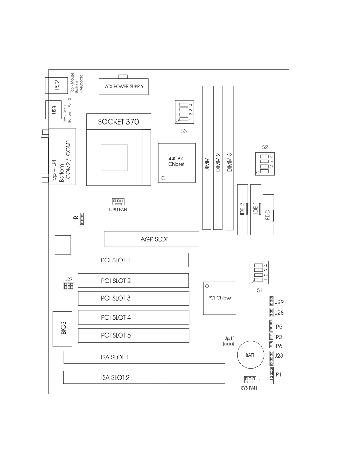
1. 2 主板结构
PM-F01 主板
Page 8
第二章 硬件安装
2.1 CPU
主板可选 Intel Celeron 或 Pentium III Coppermine 处理器.Socket 370 插座
更易进行 CPU 安装
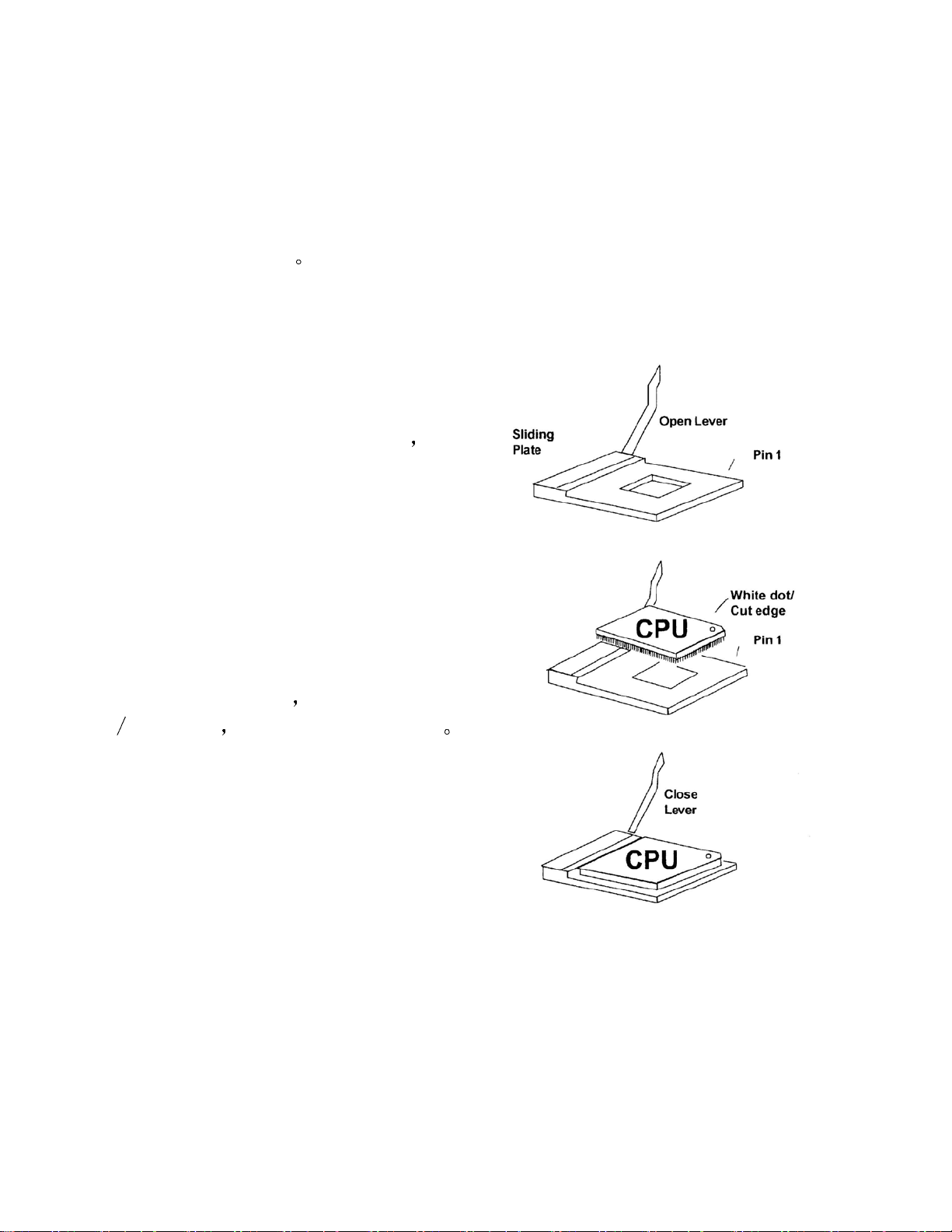
2.1.1 CPU 安装步骤
a.托动控制杆平向外侧拉离插座
向上竖立成 90 度角
b.定位插座中 Pin 1 的位置并找到 CPU
上白色的点/剪切口
CPU 需配置一个热接收器和一个风扇以防止过热
再
使 Pin 1 和白点
锯齿相对 然后很容易插入 CPU
c.压下固定控制杆则完成安装
Page 9
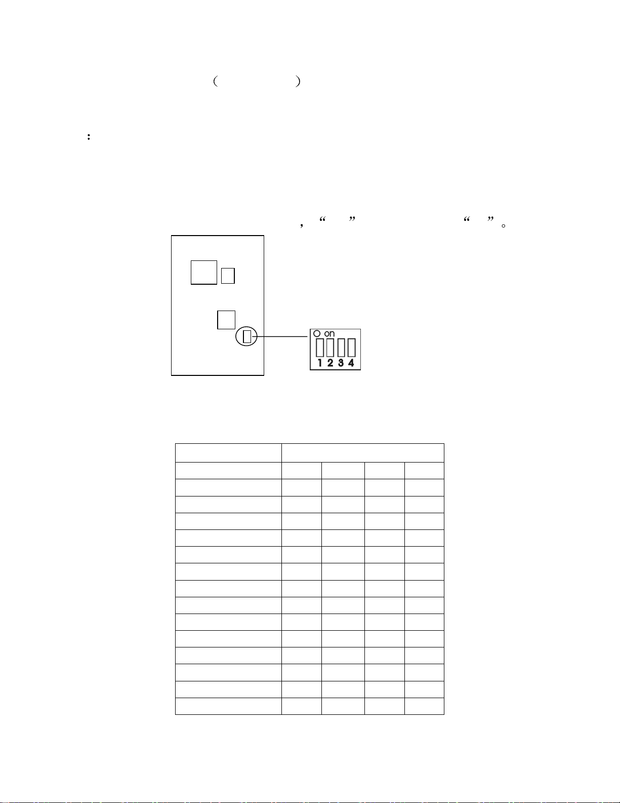
2.1.2 CPU 倍频设置 S1 Dip 开关
CPU 主频=CPU 外频×CPU 倍频
例
CPU 外频 = 100MHZ
CPU 倍频 = 5.5
则 CPU 主频 = 100MHZ×5.5
=550MHZ
请调整 S1 dip 开关改变 CPU 倍频
CPU 倍频 S1 Dip 开关
1 2 3 4
1.5X On Off Off Off
2X On On
2.5X On On Off On
3X On Off On On
3.5X On Off Off On
4X Off On On On
4.5X Off On Off On
5X Off Off On On
5.5X Off Off Off On
6X On On On Off
6.5X On On Off Off
7X On Off On Off
7.5X On Off Off Off
8X Off On On Off
ON
是把 dip 设置成 开
On
On
Page 10
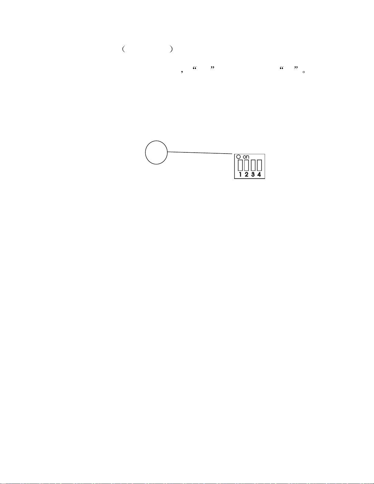
2.1.3 CPU 外频设置 S2 Dip 开关
请调整 S2 dip 开关改变 CPU 外频
ON
是把 dip 设置成 开
Page 11

S2 Dip 开关– CPU 外频设
推 荐
推 荐
推 荐
CPU 外频 PCI 外频
66.8 MHz 33.4 MHz Off Off On On
75 MHz 37.5 MHz
83.3 MHz 41.65 MHz On Off On On
100.3
MHz
103 MHz 34.3 MHz On On Off On
105 MHz 35 MHz Off Off On Off
110 MHz 36.67 MHz On Off On Off
112 MHz 37.33 MHz Off On Off On
115 MHz 38.33 MHz Off On On Off
120 MHz 40 MHz On On On Off
124 MHz 31 MHz On Off Off Off
133 MHz 33.25 MHz Off Off Off Off
133 MHz 44.33 MHz On Off Off On
140 MHz 35 MHz On On Off Off
150 MHz 37.5 MHz Off On Off Off
33.3 MHz Off Off Off On
1 2 3 4
Off
On On On
警告
或最终用户超频使用
除了在正常的 CPU 外频 被推荐 上 其它的则可用于内部测试
可能会导致你的系统不稳定或严重损坏
Page 12
2.1.4 Intel处理器或 Cyrix处理器 S3 Dip 开关
使用 Imtel 处理器或 Cyrix 处理器
Intel CPU
CPU 外频 S3 Dip 开关
1 3 4
66 MHz /自动检测
100 MHz Off Off On
133 MHz Off Off Off
Cyrix CPU
CPU 外频 S3 Dip 开关
1 3 4
66 MHz / 自动检测
100 MHz Off On Off
133 MHz Off Off Off
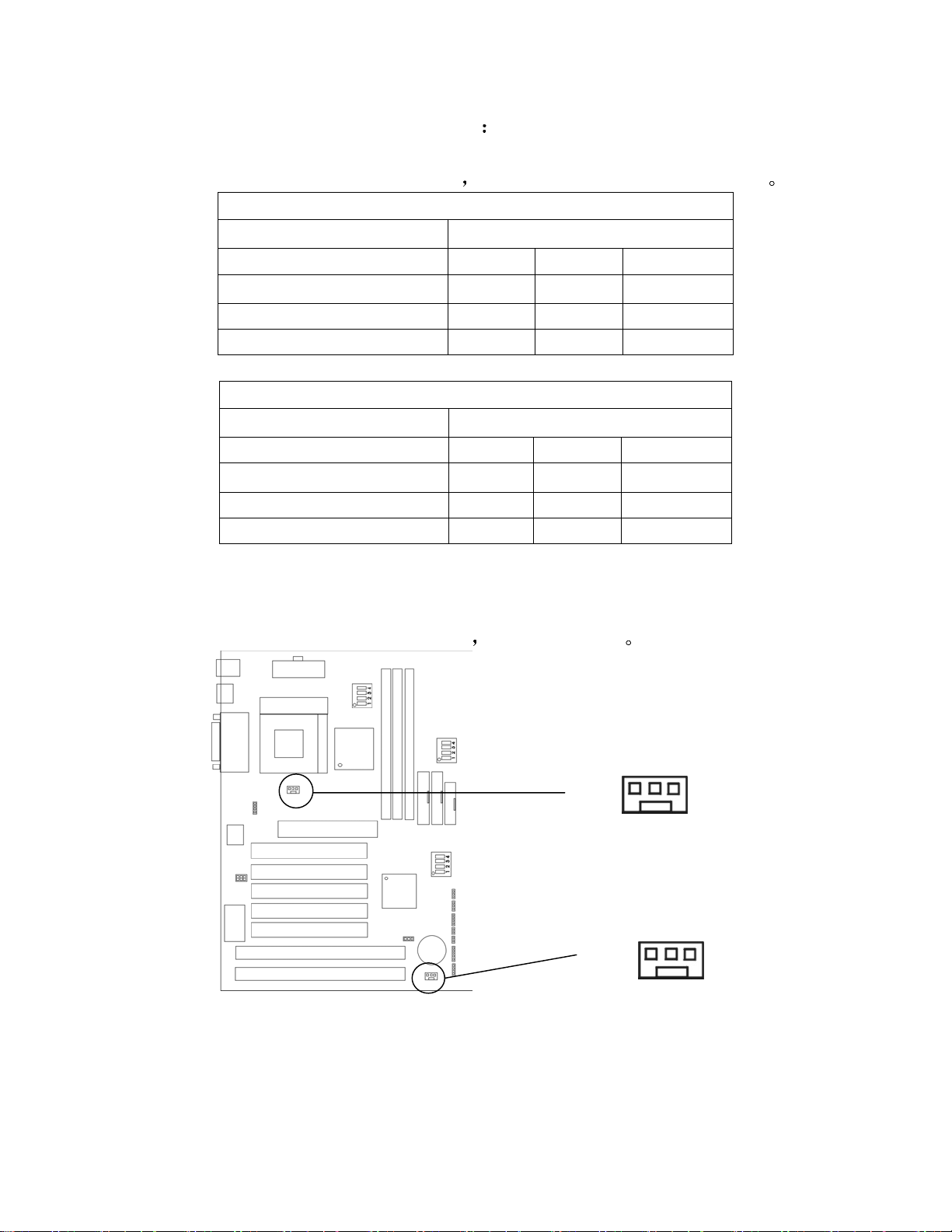
2.1.5 CPU 风扇接口
应按如下表格设置 S3 dip 开关
On Off On
On On Off
此接口支持 +12V 的系统致冷风扇
支持三针接口
CPU 风扇
SYS / CHASIS 风扇
Page 13
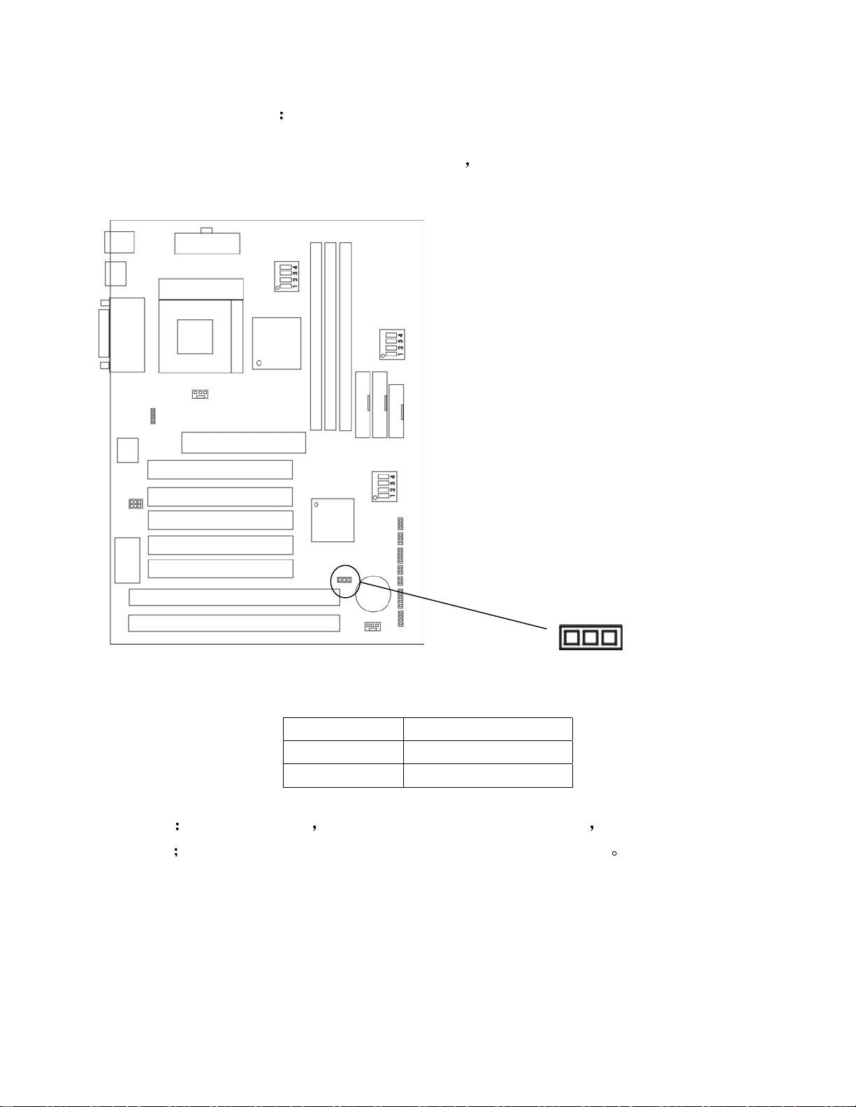
2.1.6 CMOS 跳线 JP11
电池用来保持主板的 CMOS RAM 配置
数据
JP11 的 1-2 针用来存储 CMOS
3 2 1
Short Pin CMOS
1-2 Keep Data
2-3 Clear Data
注意
位置
将系统关闭后 你能用短接 2-3pin 擦除 CMOS 重新设成 1-2pin
当系统打开的时候避免擦除 CMOS 以免损坏主板
Page 14
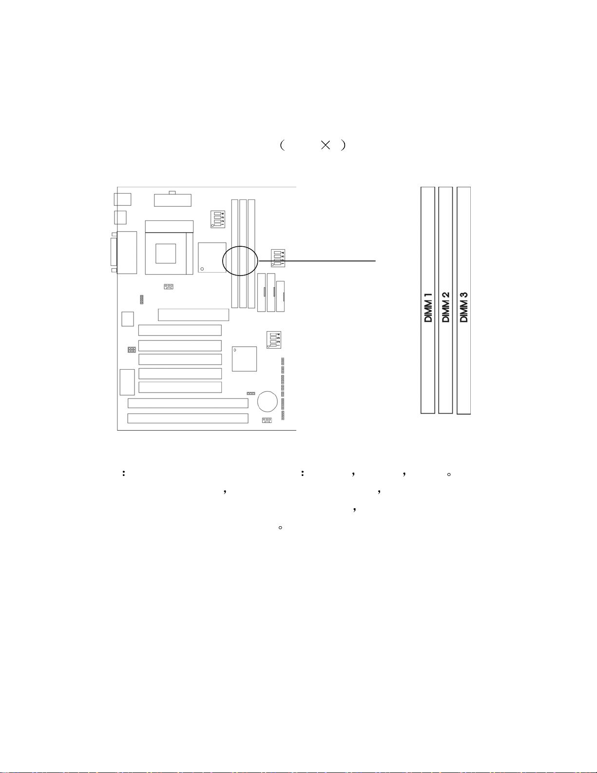
2. 2 内存安装
2.2.1 内存组合配置
主板支持最大的内存为 768MB
buffered DIMM(Double In-Line Memory Module)插座
256M 3
它提供 3 个 168-pin non-
警告
66MHz CPU 总线频率
总线频率, 可支持 PC100 和 PC133 的 DIMM
线频率,仅支持 PC133 的 DIMM
主板支持三种指定的 DIMM
可支持三种 DIMM 规格 如果你用 100MHz CPU
PC133 PC100 PC66
如果你用
如果你用 133MHz CPU 总
Page 15
内存速度正常定位于
-15 -12 -10 -7 -8 PC-100 PC-133
解释
-12=12ns 最大的时钟是 83MHz
PC-100/PC133 = 新的 Intel 规格的用于 100MHz 或更高 CPU 总线时钟的
高速内存
此主板支持以上所有内存速度
CPU 总线时钟
100SDRAM
2.2.2 内存安装步骤
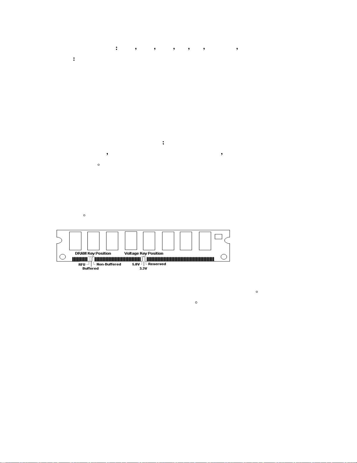
a. DIMM 槽有 2 个凹口’volt and DRAM’,所以 DIMM 内存只能适合一个
-15=15ns,最大的时钟是 66MHz
-10=10ns 最大的时钟是 100MHz
-7=7ns 最大的时钟是 125MHz
-8=8ns 最大的时钟是 142MHz
为了得到更好的性能和可靠性 我们建议你使用 PC-
方向
如果你的系统设置为 100Mhz 或更高
b.把 DIMM 内存模块垂直插入 DIMM 槽,然后推到里面去
c.在 DIMM 槽侧面的塑胶夹将自动关闭
Page 16
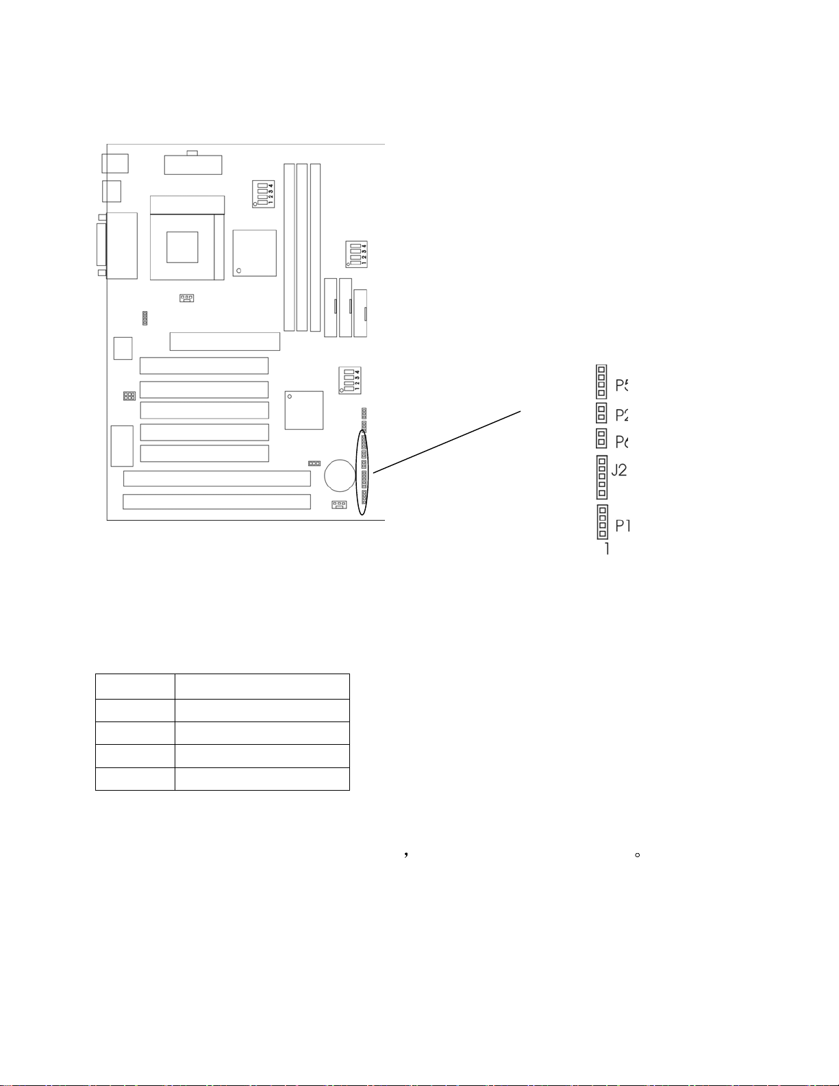
2.2 机箱连接口
HDD
PWR
RST
KEYLOCK
SPEAKER
硬盘活动指示灯: P5 HDD
HDD LED 显示硬盘的活动状态,当 HDD LED 发亮的时候要避免关掉电源.
你可以把 HDD LED 从系统机箱连到 P5 针
Pin
1
说 明
Active Signal
2 Ground
3 Ground
4 Active Signal
ATX 软开关接口: P2 PWP
从机箱上的电源开关连接此针 P2 它提供即时 ON/OFF 功能
Page 17

RESET 接口: P6 RST
RESET 开关用来重新启动相当于按电源开关 ON/OFF , 当 HDD LED 闪烁
时,不要重新启动
设置 说 明
打开
关闭
键盘和电源指示灯接口: J23 KEYLOCK
键盘允许你为安全用途锁定键盘 可以把 keylock 连接到此针 J23
Pin
1 LED output
2 N.C.
3 Ground
4 Keylock
5 Ground
扬声器接口
Normal mode
Reset system
说 明
P1 SPEAKER
从机箱上的 RESET 开关连接此针 P6
扬声器从机箱连接到这个 P1 针
Pin
1 Data out
2 N.C.
3 Ground
4 +5V
说 明
Page 18
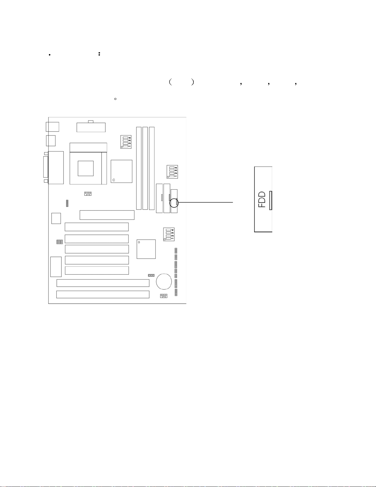
2 3 软驱接口 FDD
主板也提供一个标准的软驱接口
和 2.88M 软驱类型
FDD ,支持 360K 720K 1.2M 1.44M
Page 19
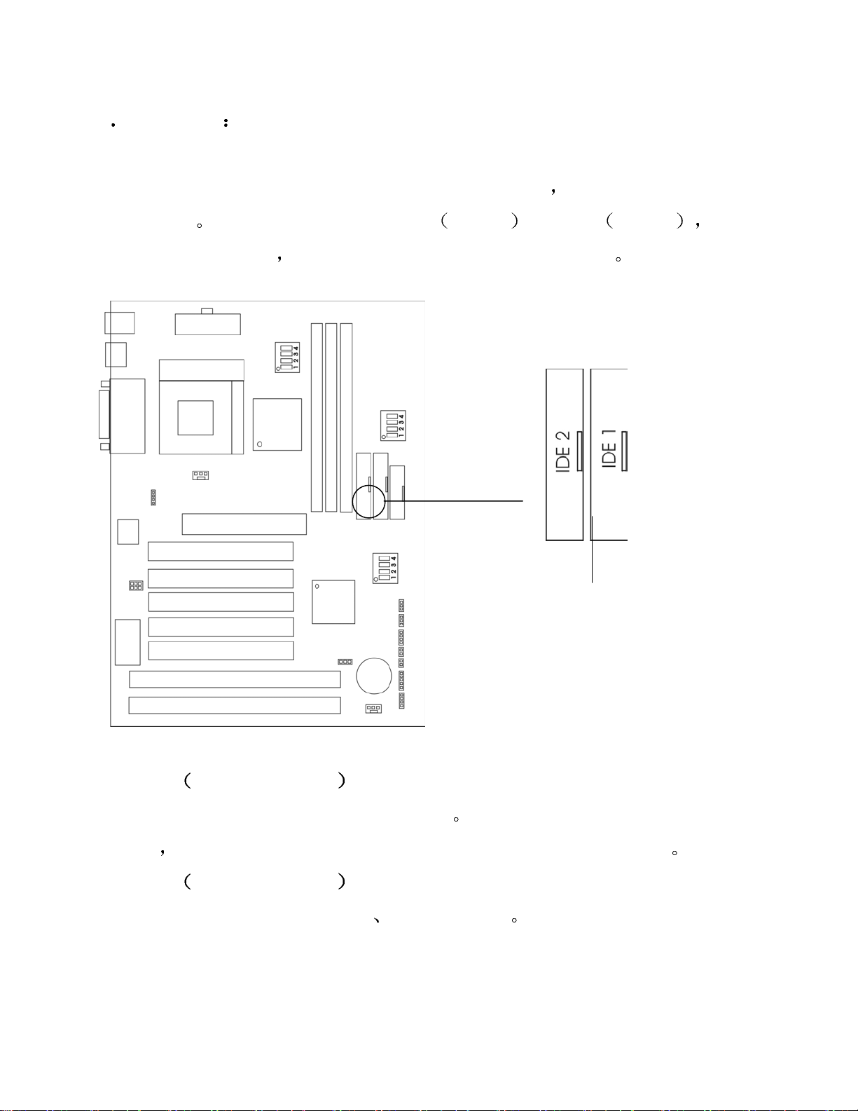
2 4 硬盘接口 IDE1&IDE2
主板有一个 32-bit 增强 IDE 控制器提供 PIO mode 0-4
DMA 33/66
连接 4 个硬盘驱动器
它有 2 个 HDD 接口 IDE1 第一个 和 IDE2 第二个 你能
CD-ROM 和其它装置到 IDE1 和 IDE2
Bus Master 和 Ultra
IDE1
第一个 IDE 接口
第一个硬盘驱动器应总是连接到 IDE1
驱动器
IDE2
你必须用设置跳线来配置第二个硬盘驱动器成为从盘模式
第二个 IDE 接口
IDE2 也能连接一个主驱动器
IDE1 能连到一个主盘和一个从盘
一个从驱动器
IDE 1 用蓝色标记
Page 20
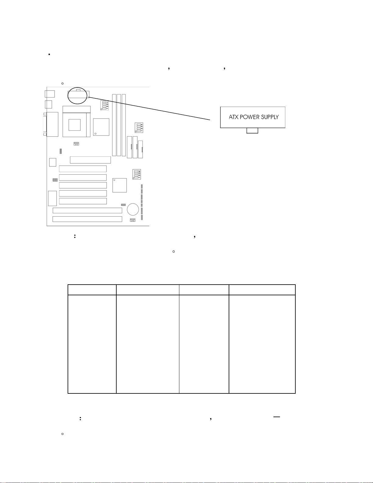
2 5 供电电源
这个接口支持板上的电源按钮
功能
警告
因为主板有即时电源打开功能 所以在插入电源接口之前要确信所
用 ATX 电源 本主板提供 Modem 唤醒等
有组件已正确安装以避免发生危险
ATX 电源支持一个 20 针接口
Pin Description Pin Description
3.3V
3.3V
Ground
+5V
Ground
+5V
Ground
Power OK
5VSB
+12V
NOTE
1
2
3
4
5
6
7
8
9
10
一些 ATX 电源没有-5V 电压输出 它将影响 ADD
11
12
13
14
15
16
17
18
19
20
3.3V
-12V
Ground
PS-ON
Ground
Ground
Ground
-5V
+5V
+5V
ON 卡设备的
功能
Page 21
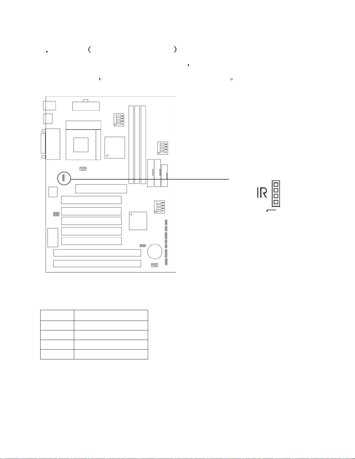
2 6 红外线 IrDA Infrared Module
接头连接
主板提供 4 针 IR 模式红外线接头连接
接收红外线模式
你必须通过 BIOS 设置使用 IR 功能
这个接头连接是可选无线传输和
Pin
1 VCC
2 IRRX
3 Ground
4 IRTX
说 明
Page 22
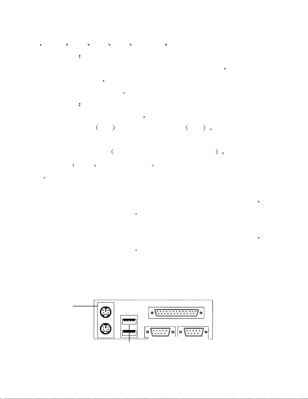
2 7 串行
并行
USB
鼠标 键盘接口
串行端口接口
主板的串行端口 COM1 和 COM2 拥有 2 个 9 针凸出 DIN 接头
16550A 高速通讯端口
Modem 线直接接入这个接口
并行端口接头
主板为 LPT 提供一个 25 针凹口
支持增强并行端口
COM1 和 COM2
发送/接收 16bytes FIFOS 你能把一个鼠标或一根
LPT
EPP
和扩展容量并行端口
这些端口是
一个并形端口是一个标准的打印端口也
ECP
USB 接口
主板支持一个 UHCI
USB 设备如
口
键盘 鼠标和其它 USB 你能直接插上 USB 设备到这个接
Universal Host Controller Interface
串行总线连接
鼠标接口
主板提供一个标准的 PS/2 鼠标最小化 DIN 连接口用于连接 PS/2 鼠标
你
能直接插入一个鼠标到这个接口
键盘接口
主板提供一个标准的 PS/2 键盘最小化 DIN 连接口用于连接 PS/2 键盘
能直接插入一个键盘到这个接口
LPT
Top: PS/2
Mouse
Bottom: PS/2
COM1 COM2
Top: USB Port 2
Bottom: USB Port 1
你
Page 23
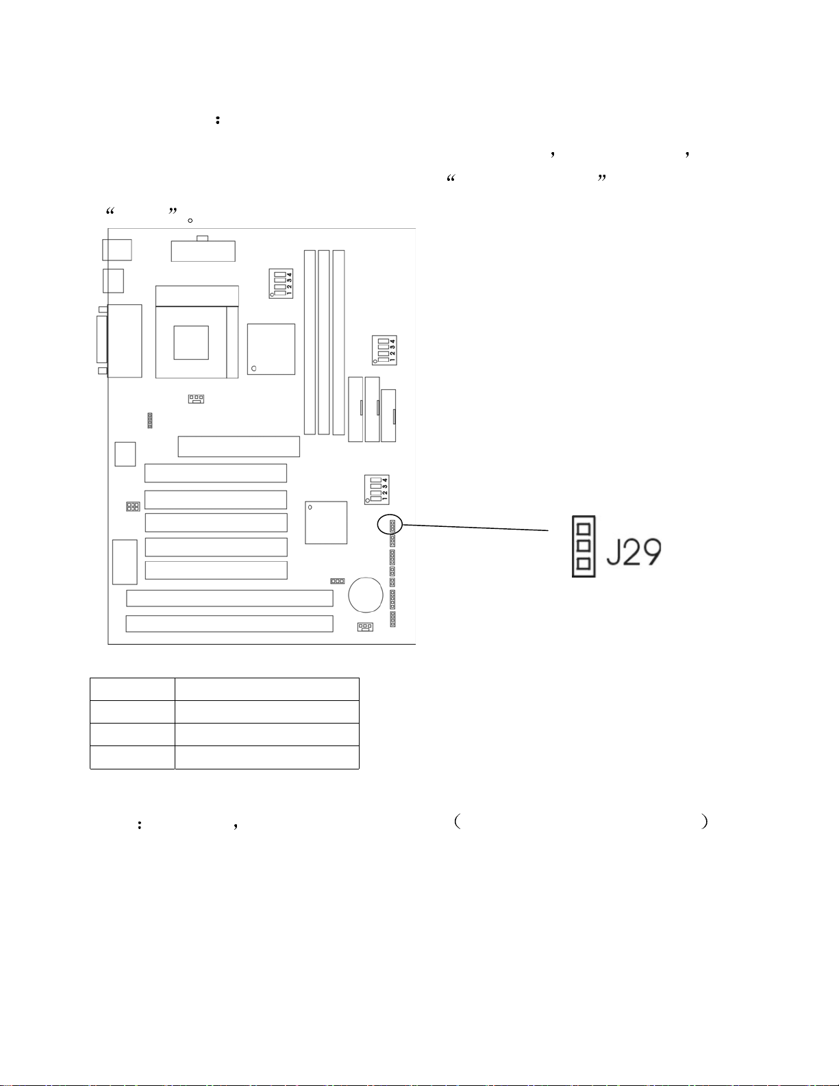
2.8 LAN 唤醒 J29 WVL
J29 接口是用 LAN add-on cards 支持 LAN 唤醒功能
要在 BIOS Power Management Setup 中把
enable
Wake-up on LAN
使用这个功能 你需
设置为
PIN SIGNAL
1 5VSB
2 GND
3 WAKE-UP SIGNAL
注意
用此功能 你需要足够的电源供应 电源支持 740ma 5V Stand-by
1
Page 24
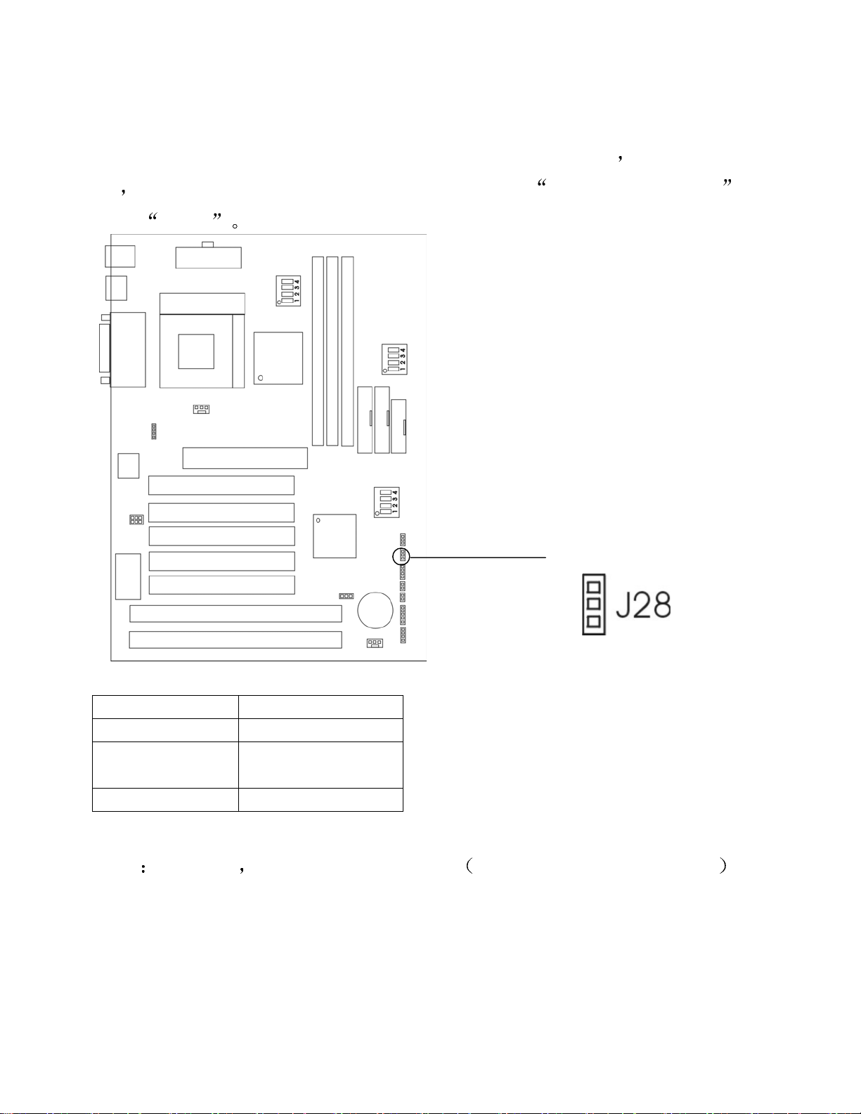
2.9 Modem 唤醒
J28 接口是用于支持 Modem 唤醒功能 Modem add-on Card
能
你需要在 BIOS Power Management Setup 中把
置为
enable
要使用此功
Modem Ring Resume
设
1
PIN SIGNAL
1 5VSB
2 WAKE-UP
SIGNAL
3 GND
注意
用此功能 需要有供应足够的电源 电源支持 740ma 5V Stand-by
Page 25
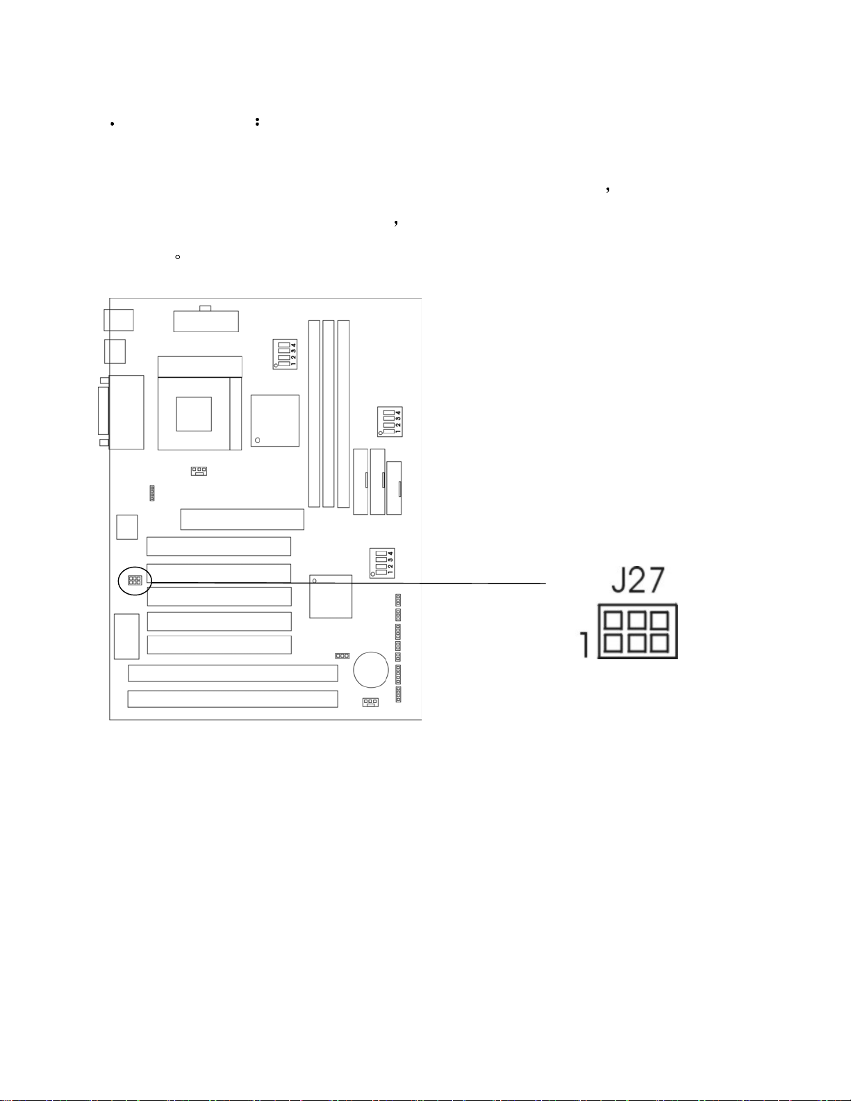
2 10SB-link 接口 J27 SBLINK
SBLINK 是一个特殊使用的用于 Creative PCI 声卡的接口
根连线从 ISA 总线连接到 PCI 声卡
ISA 总线
这是因为一些基于 DOS 的游戏定位于
SB-link 通过一
Page 26

Chapter 3 BIOS SETUP
BIOS ROM 有一个内建设置程序
它允许用户修改基本系统配置 此类型信
息被储存在 battery-backed RAM (CMOS RAM), 因此当电源关闭后
置信息
能保留设
3.1 进入设置程序
打开计算机后立即按 <Del>键可进入设置程序 另一个方法是打开计算机电
源
在自测时
ESC> OR <DEL> KEY
<Ctrl><Alt>和<Esc>
如果信息在你反应之前未出现而你仍然想进入设置程序
计算机或按机机箱上的“RESET”键
<Delete>键重新启动计算机
引导
将显示出下列一个错误信息
TO ENTER SETUP BEFORE BOOT PRESS <CTRL-ALT-
出现在屏幕的底部 此时按<Del>键或同时按下
请重新关闭再打开
你也可以同时按<Ctrl><Alt> and
如果你不能适时按下
del.>键并且系统不能被
PRESS <F1> TO CONTINUE, <CTRL-ALT-ESC> OR <DEL> TO ENTER
SETUP
3.2 获得帮助
Main Menu
The on-line description of the highlighted setup function is displayed at the bottom
of the screen.
Status Page Setup Menu / Option Page Setup Menu
Press F1 to pop up a small help window that describes the appropriate keys to use
and the possible selections for the highlighted item. To exit the Help Window,
press <F1> or <ESC>.
Page 27
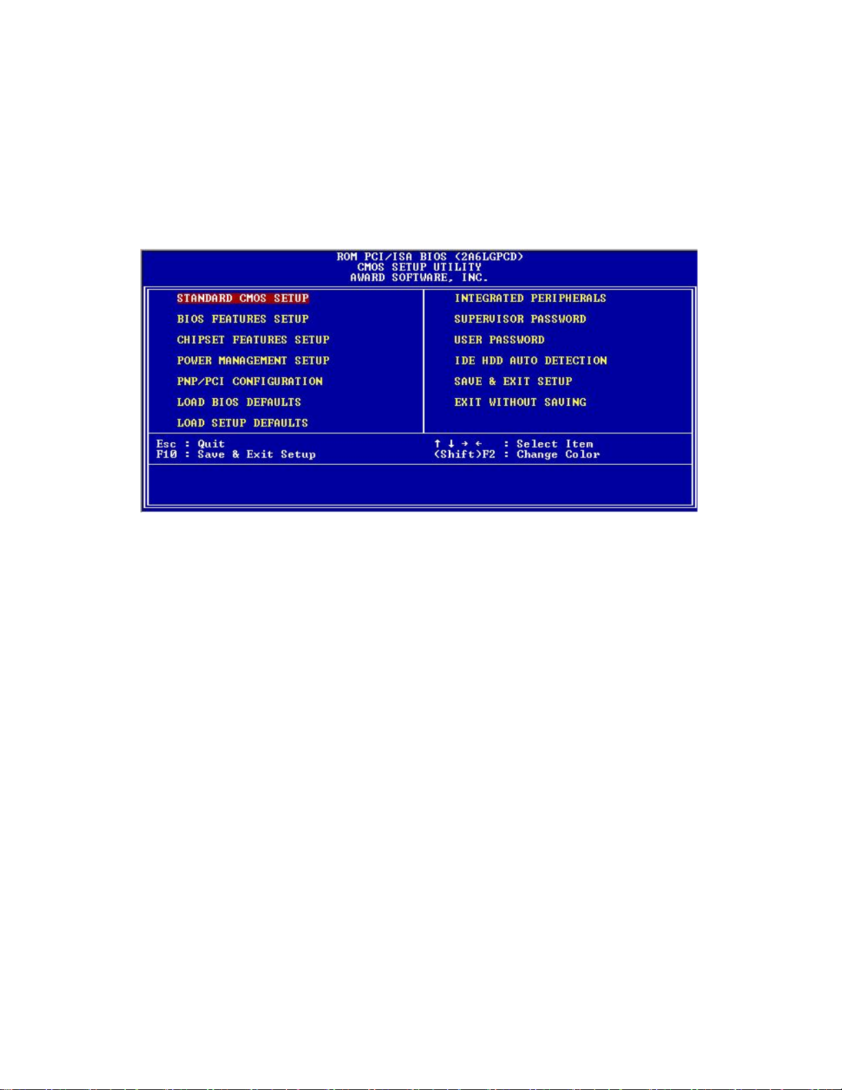
3.3 The Main Menu
Once you enter BIOS CMOS setup utility, the Main Menu will appear on the
screen. The Main Menu allows you to select from eleven setup functions and two
exit choices. Use arrow keys to select among the items and press <Enter> to accept
or enter the sub-menu.
Standard CMOS Setup
This setup page includes all the items in a standard compatible BIOS.
BIOS Features Setup
This setup page includes all the items of enhanced features.
Chipset Features Setup
This setup page includes all the items of chipset special features.
Power Management Setup
This category determines the power consumption for system after setting the
specified items. Default value is Disable.
PNP/PCI Configuration
This category specifies the IRQ level for PCI and ISA devices.
Load BIOS Defaults
Chipset defaults indicates the values required by the system for stable performance.
Page 28

Load Setup Defaults
Chipset defaults indicates the values required by the system for the maximum
performance.
Integrated Peripherals
Change, set or disable onboard I/O, IRQ and DMA assignment.
Supervisor Password
Change, set or disable password. This function allows the user access to the system
and setup or just setup.
IDE HDD Auto Detection
Automatically configure hard disk parameters.
Save & Exit Setup
Save CMOS value changes to CMOS and exit setup.
Exit Without Saving
Abandon all CMOS value changes and exit setup.
Page 29
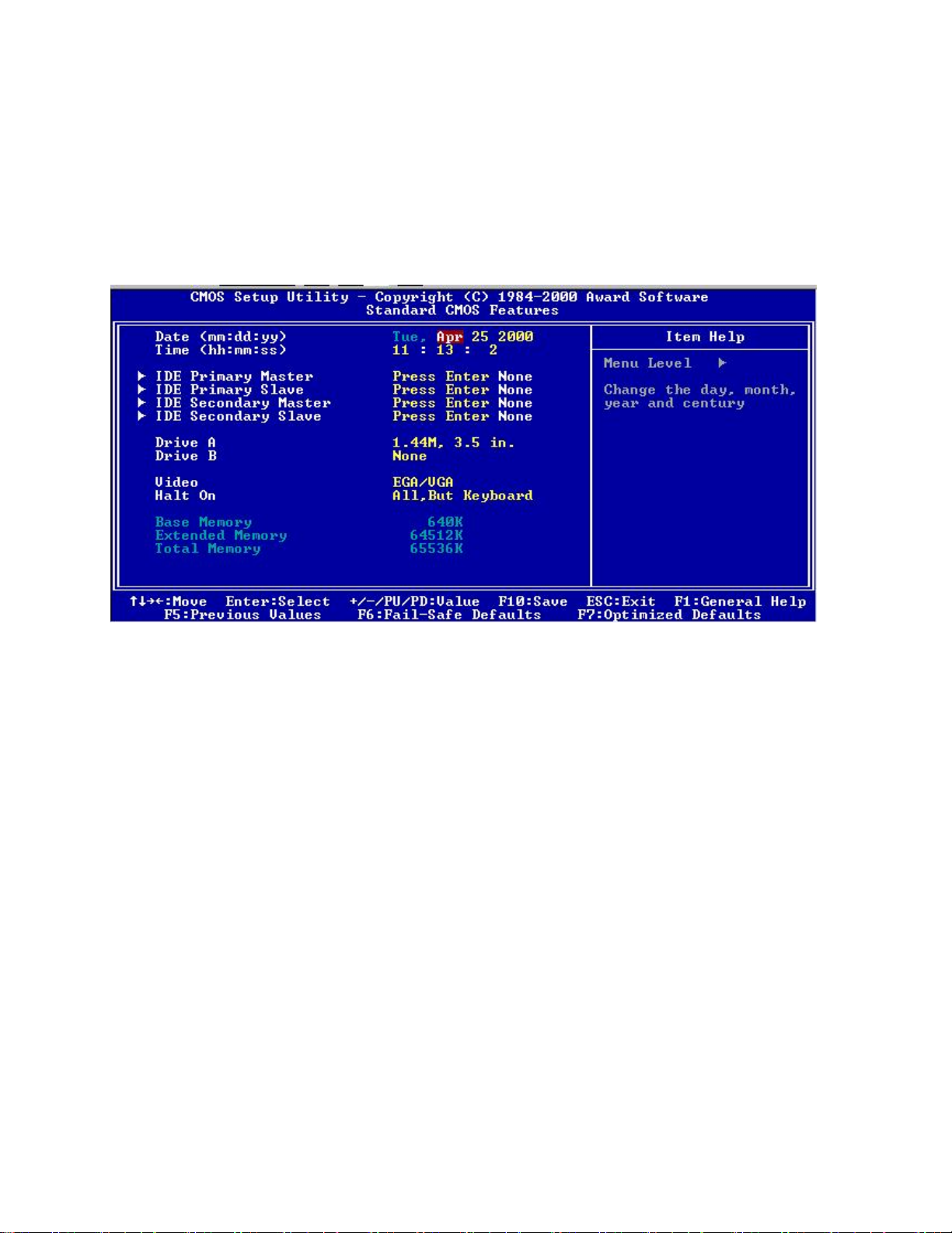
3.4 Standard CMOS Setup
The items in Standard CMOS Setup Menu are divided into 10 categories. Each
catergory includes no, one or more than one setup items. Use the arrow keys to
highlight the item and then use the <PgUp> or <PgDn> keys to select the value you
want in each item.
Date
The date format is <day><month><date><year>.
Time
The time format is <hour><minute><second>.
Primary Master / Primary Slave
Secondary Master / Secondary Slave
These categories identify the types of 2 channels that have been installed in the
computer. There are 45 pre-defined types and 4 user definable types for Enhanced
IDE BIOS. Type 1 to 45 are pre-defined. Type User is user-definable.
Press PgUp or PgDn to select a numbered hard disk type or type the number and
press <Enter>. Note that the specifications of your drive must match with the drive
table. The hard disk will not work properly if you enter improper information for
Page 30

this category. If your hard disk drive type is not matched or listed, you can use
Type User to define your own drive type manually.
If you select Type User, related information is asked to be entered to the following
items. Enter the information directly from the keyboard and press <Enter>. This
information should be provided in the documentation from your hard disk vendor
or the system manufacturer.
If the controller of HDD interface is ESDI, the selection shall be “TYPE 1”.
If the controller of HDD interface is SCSI, the selection shall be “NONE”.
If the controller of HDD interface is CD-ROM, the selection shall be “AUTO”.
CYLS number of cylinders
HEADS number of heads
PRECOMP write protection
LANDZONE landing zone
SECTORS number of sectors
MODE HDD access mode
Page 31
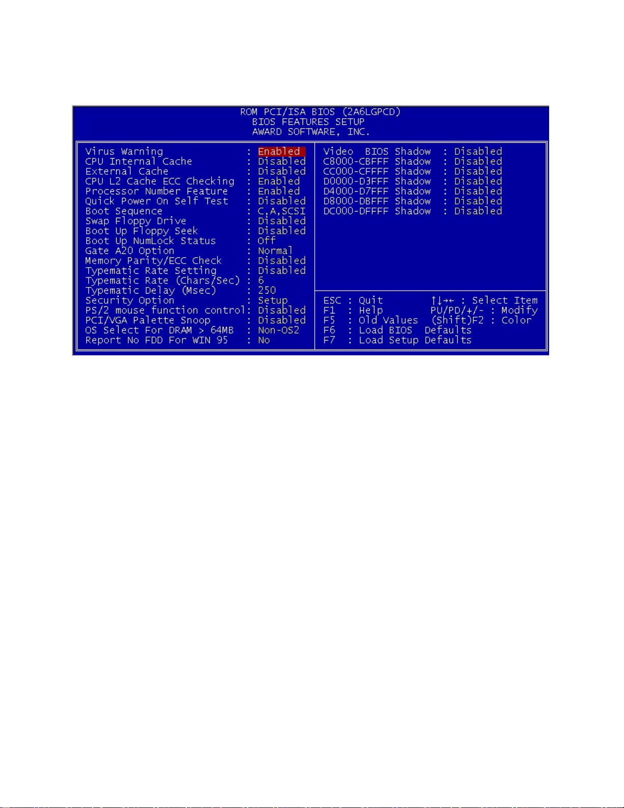
3.5 BIOS Features Setup
Virus Warning
During and after the system boots up, any attempt to write to the boot sector or
partition table of the hard disk drive will halt the system and the following error
message will appear. For the meantime, you can run an anti-virus program to
locate the problem.
Disabled
(Default)
No warning message to appear when anything attempts to
access the boot sector or hard disk partition table.
Enabled Activates automatically when the system boots up causing a
warning message to appear when anything attempts to access
the boot sector of hard disk partition table.
CPU Internal Cache
The default value is Enabled.
Enabled (Default) Enable cache
Disabled Disable cache
Note: The internal cache is built in the processor
External Cache
Choose Enabled or Disabled. This option enables the level 2 cache memory.
CPU L2 Cache ECC Checking
Choose Enabled or Disabled. This option enables the level 2 cache memory ECC
(error check correction). Using 66Mhz CPU Bus Pentium II processor, set to
Enables or Disabled. For Celeron processor w/o cache, always set to Disabled.
Page 32

Quick Power On Self Test
This category speeds up Power On Self Test (POST) after you power on the
computer. If this is set to Enabled, BIOS will shorten or skip some check items
during POST.
Enabled Enable quick POST
Disabled (default) Normal POST
Boot Sequence
This category determines which drive the computer searches first for the disk
operation system. Default value is A, C, SCSI.
Swap Floppy Drive
Switches the floppy disk drives between being designated as A and B. Default is
Disabled.
Boot Up Floppy Seek
During POST, BIOS will determine if the floppy disk drive installed is 40 or 80
tracks. 360K type is 40 tracks while 760K, 1.2M and 1.44M are all 80 tracks.
Boot Up Numlock Status
The default value is On.
On (Default) Keypad is numeric keys.
Off Keypad is arrow keys.
Gate A20 Option
Normal The A20 signal is controlled by keyboard controller or chipset
hardware.
Fast (Default) The A20 signal is controlled by port 92 or chipset specific
method.
Security Option
This category allows you to limit access to the system and Setup, or just to Setup.
System The system will not boot and access to Setup will be denied if
the correct password is not entered at the prompt.
Setup (Default) The system will boot, but access to Setup will be denied if the
correct password is not entered at the prompt.
Page 33

PCI VGA Palette Snooping
Choose Disabled or Enabled. Some graphic controllers which are not VGA
compatible, take the output from a VGA controller and map it to their display as a
way to provide the boot information and the VGA compatibility.
However, the color information coming from the VGA controllers is drawn from
the palette table inside the VGA controller to generate the proper colors, and the
graphic controller needs to know what is in the palette of the VGA controller. To
do this, the non-VGA graphic controller watches for the Write access to the VGA
palette and registers the snoop data. In PCI based systems, where the VGA
controller is on the PCI bus and a non-VGA graphic controller is on an ISA bus, the
Write Access to the palette will not show up on the ISA bus if the PCI VGA
controller responds to the Writes.
In this case, the PCI VGA controller should not respond to the Write. It should
only snoop the data and permit the access to be forwarded to the ISA bus. The
non-VGA ISA graphic controller can then snoop the data on the ISA bus. Unless
you have the above situation, you should disable the option.
Disabled
Disable the function
(Default)
Enabled Enable the function
OS Select for DRAM > 64MB
Allows OS2 to be used with > 64MB of DRAM. Setting are non-OS/2 (default)
and OS2. Set to OS/2 if using more than 64MB and running OS/2.
Report No FDD For Win95
This function is only used when you are testing SCT for Window 95 Logo.
Video BIOS Shadow
Determines whether video BIOS will be copied to RAM for faster execution.
Video Shadow will increase the video performance.
Enabled (Default) Video shadow is enabled.
Disabled Video shadow is disabled.
C8000-CBFFF / DC000-DFFFF Shadow
Determine whether the optiomal ROM will be compiled to RAM for faster
execution.
Page 34
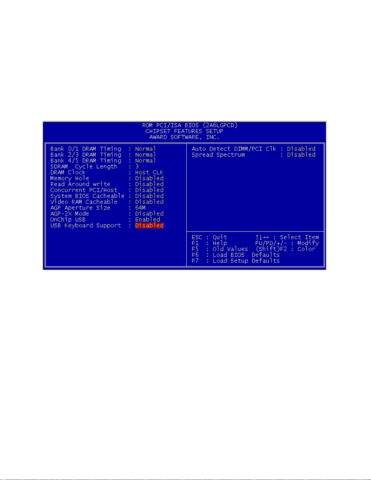
3.6 Chipset Features Setup
The Chipset Features Setup option is used to change the values of the chipset
registers. These registers control most of the system options in the computer.
Choose the “CHIPSET FEATURES SETUP” from the Main Menu and the
following screen will appear.
Note: Change these settings only if you are familiar with the chipset.
Bank 0/1 DRAM Timing / Bank 2/3 DRAM Timing / Bank 4/5 DRAM Timing
Set the DRAM latency time to SDRAM 10ns, 8ns, Normal, Medium, Fast and
Turbo.
SDRAM Cycle Length
The item allows you to select the value for SDRAM Cycle delay time. The settings
are 2ns or 3ns. The default value is 3ns.
DRAM Clock
The defalult value for this item is Host Clk.
Host Clk DRAM Clock equals to host (system clock).
HCLK-33M DRAM Clock equals to host clock minus 33Mhz.
Page 35

Memory Hole At 15M-16M
In order to improve the system’s performance, certain space in memory can be
reserved for ISA cards. This memory must be mapped into memory space below
16MB.
Enabled Memory hole supported
Disabled Memory hole not supported
Concurrent PCI / Host
Select Enabled allows caching of the system BIOS ROM at F000h-FFFFFh,
resulting in better system performance. However, if any program writes to this
memory area, a system error may result.
Enabled BIOS access cached
Disabled BIOS access not cached
Video Ram Cacheable
Select Enabled allows caching of the video RAM, resulting in better system
performance. However, if any program writes to this memory area, a system error
may result.
AGP Aperture Size
Select the size of the Accelerated Graphics Port (AGP) aperture. The aperture is a
portion of the PCI memory address range dedicated for graphics memory address
space. Host cycles that hit the aperture range are forwarded to the AGP without
any translation.
Onchip USB
This items allows you to Enable or Disable the USB function. The default value of
this item is Enabled.
USB Keyboard Support
This items allows you to Enable or Disable the USB keyboard function. The
default setting is Disabled.
Auto Detect DIMM / PCI Clk
This items allows you to select the DIMM/ PCI clock. The other sockets will not
generate when DIMM / PCI cards are not installed. The setting should be set to
enabled which works better for EMI.
Spread Spectrum
This item allows you to select the clock generator Spread Spectrum function and
system bus frequency (CPU Clock). The default is CPU default frequency. If you
over-clock the processor, the system will hang-up. (Press F10 to resume to the
original value)
Page 36
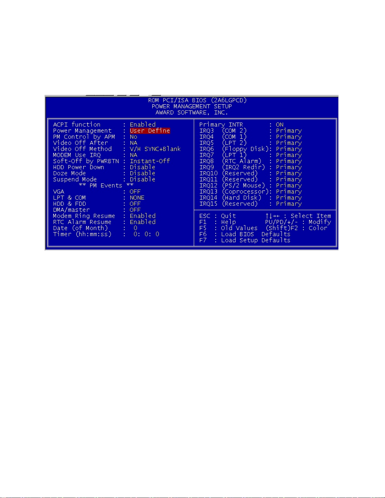
3.7 Power Management Setup
The Power Management Setup will appear on your screen like this:
Power Management
This category determines the power consumption for system after selecting below
items. Default value is user define. The following pages tell you the options of
each item & describe the meanings of each options.
ACPI Function
This item allow you to enable or disable the ACPI function.
Enabled (Default) Enable the ACPI function
Disabled Disable the ACPI function
Power Management
Disable Global power management will be disabled.
User Define Users can configure their own power management.
Min Saving Pre-defined timer values are used such that all timers are in
their MAX value.
Max Saving Pre-defined timer values are used such that all timers are in
their MIN value.
Page 37

PM Control by APM
No System BIOS will ignore APM when power managing the
system.
Yes System BIOS wil wait for APM’s prompt before it enter any
PM mode.
Note: Enable this for OS with APM like Windows 95/98, Windows NT etc.
Video off Method
Blank Screen The system BIOS will only blank off the screen when
disabling video.
V/H SYN
C+Blank
DPMS This function is enabled only for VGA card supporting DPMS.
Note: Green monitors detect the V/H SYNC signals to turn off its electron gun.
Modem Use IRQ
Name the interrupt request (IRQ) line assigned to the modem (if any) on your
system. Activity of the selected IRQ always awakens the system. The settings are
NA, 3, 4, 5, 7, 9, 10 or 11.
Soft-Off by PWRBTN
The settings are Delay 4 sec or Instant-Off. During Delay 4 sec, if you push the
switch once, the system goes into suspend mode. If you push it more than 4
seconds, the system will be turn off. During Instant-off, the system will turn off
once you push the switch.
HDD Power Down
Disable HDD’s motor will not shut off.
Predefined Mins. Defines the continuous HDD idle time before the HDD enters
Doze Mode
Disable System will never enter DOZE mode.
Predefined Mins. Defines the continuous System idle time before the system
Suspend Mode
Disable System will never enter Suspend mode.
Predefines Mins. Defines the continuous idle time before the system enters
In addition to (1), BIOS will also turn off the V-SYNC & H-
SYNC signals from VGA card t monitor.
the power saving mode (motor off). BIOS will turn off the
HDD’s motor when time is out.
enters DOZD mode.
Suspend mode. If any item defined in the options of “Power
Down & Resume Events” is enabled & active, Suspend timer
will be reloaded. When the system has entered Suspend mode,
any of the items enabled in the “Power Down & Resume
Events” will trigger the system to wake up.
Page 38

Wake Up On LAN
To use this function, you need a LAN add-on card which support power on
functions.
Enabled Wake up on LAN supported.
Disabled Wake up on LAN not supported.
Modem Ring Resume
To use this function, you need a Modem card which support power on functions.
Enabled Wake up on Internal modem supported
Disabled Wake up on Internal modem not supported
RTC Alarm Resume
This function is for setting date and time for your computer to boot up. During
disabled, you cannot use this function. During Enabled, choose the Date and Time
Alarm:
Date (of month)
Alarm
Time Alarm You can choose what hour, minute and second the system will
Note: If you have change the setting, you must let the system boot up until it goes
to the operating system, before this function will work.
You can choose which date the system will boot up, Set to 0,
to boot everyday.
boot up.
Page 39
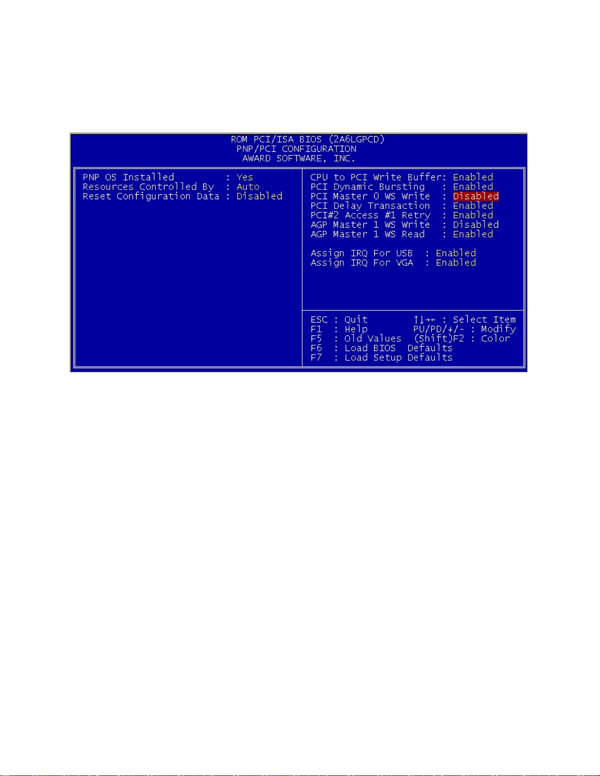
3.8 PNP/PCI Configuration Setup
You can manually configure the PCI Device’s IRQ. The following pages tell you
the options of each item and describe the manings of each options.
PnP OS Installed
When set to YES, BIOS will only initialize the PnP cards used for booting (VGA,
IDE, SCSI). The rest of the cards will be initialized by the PnP operating system
like windows 95/98. When set to NO, BIOS will initialize all the PnP cards. So,
for non-PnP operating system (DOS, Netware), this option must set to NO.
Resources Controlled By
By choosing “AUTO”, the system BIOS will detect the system resources and
automatically assign the relative IRQ and DMA channel for each peripheral.
By choosing “MANUAL” (default), the user will need to assign IRQ and DMA for
add-on cards. Be sure that there is no conflict for IRQ/DMA and I/O ports.
Note: When choosing “AUTO”, you must be sure that all of the system add-on
cards are PnP type.
Reset Configuration Data
The system BIOS supports the PnP feature so that the system needs to record which
resource is assigned and protect resources from conflict. Every peripheral device
has a node which is called ESCD. This node records which resources are assigned
to it. The system needs to record and update ESCD to the memory locations.
These locations (4K) are reserved at the system BIOS.
Page 40

If Disabled (default) is chosen, the system’s ESCD will update only when the new
configuration varies from the last one.
If Enabled is chosen, the system will be forced to update the system’s ESCD. Then,
this option will be auto-set to Disable.
IRQ-3 assigned to Legacy ISA
IRQ-4 assigned to Legacy ISA
IRQ-5 assigned to PCI/ISA PnP
IRQ-7 assigned to Legacy ISA
IRQ-9 assigned to PCI/ISA PnP
IRQ-10 assigned to PCI/ISA PnP
IRQ-11 assigned to PCI/ISA PnP
IRQ-12 assigned to PCI/ISA PnP
IRQ-14 assigned to PCI/ISA PnP
IRQ-15 assigned to PCI/ISA PnP
DMA-0 assigned to PCI/ISA PnP
DMA-1 assigned to PCI/ISA PnP
DMA-3 assigned to PCI/ISA PnP
DMA-5 assigned to PCI/ISA PnP
DMA-6 assigned to PCI/ISA PnP
DMA-7 assigned to PCI/ISA PnP
The above settings will be shown on the screen only if “Manual’ is chosen for the
Resources Controlled by function.
Legacy is the the term which signifies that a resource is assigned to the ISA Bus
and provides for non PnP ISA add-on card. PCI/ISA PnP signifies that a resource
is assigned to the PCI us or provides for ISA PnP add-on cards and peripherals.
PCI Delay Transaction
This items allows you to Enable /Disable the PCI delay transaction.
Enabled Delay transaction timing
Disabled Transaction in normal mode
Assign IRQ for USB
This item allows the user to Enable/Disable the Assign IRQ for USB.
Enabled Choose which IRQ to assign for USB
Disabled Will not assign IRQ for USB
Assign IRQ for VGA
This item allows the user to Enable/Disable the Assign IRQ for VGA.
Enabled Choose which IRQ to assign for VGA
Disabled Will not assign IRQ for VGA
Page 41
3.9 Load BIOS / Setup Defaults
This Main Menu item loads the default system values. If the CMOS is corrupted,
the defaults are loaded automatically. Choose this item and the following message
appears:
“Load Setup Defaults (Y/N) ? N”
To use the Setup defaults, change the prompt to “Y” and press <Enter>.
Note: The setup defaults can be customized to increase performance. However,
the BIOS defaults can always be used as a back up if there is some problem with
the mainboard operation.
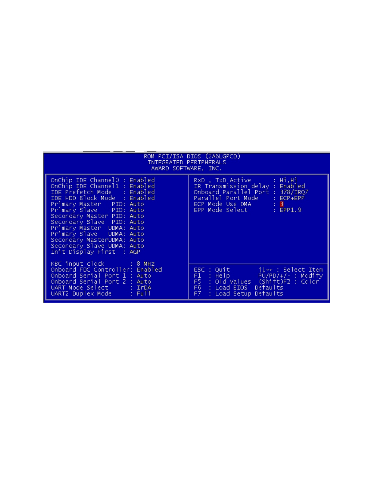
3.10 Integrated Peripherals
IDE HDD Block Mode
Enabled/Disabled Enabled allows the Block mdoe access for the IDE HDD.
IDE Primary Master PIO
IDE Primary Slave PIO
IDE Secondary Master PIO
IDE Secondary Slave PIO
Auto / Mode 0 / Mode 1-4
Page 42

For these 4 IDE options, choose “Auto” to have the system BIOS auto detect the
IDE HDD operation mode for POI access.
Note: Some IDE HDD cannot operate at the responding HDD’s mode. When the
user has selected “Auto” and the system BIOS bas accepted the HDD response
mode, the user may degrade the HDD’s operation mode. e.g. If the HDD reported
that it can operate in mode 4 but it is not operating properly, the user will have to
manually change the operation mode to mode 3.
Choosing Mode 1-4 will have the system ignore the HDD’s reported operation
mode and use the selected mode instead.
Note: According to ATA specs. Mode 4 transfer rate is > Mode 3 > Mode 2 >
Mode 1 > Mode 0. If the user’s HDD can operate at Mode 3 the user can
also select a slower Mode (i.e. Mode 0-2) but not a faster Mode (i.e. Mode 4)
On-Chip Primary PCI IDE / On-Chip Secondary PCI IDE
Enabled / Disabled
The system provides for an ON-Board ON-Chipset PCI IDE controller that
supports Dual Channel IDE (Primary and Secondary). A maximum of 4 IDE
devices can be supported. If the user install the Off-Board PCI IDE controller (i.e.
add-on cards), the user must choose which channels will be disabled. This will
depend on which channel will be used for the Off-Board PCI IDE add-on card.
Init Display First
PCI Slot If both PCI VGA card and AGP card are installed, the system
will display the PCI VGA card first.
AGP If both PCI VGA and AGP card are installed, the system will
show the AGP card first.
Onboard FDC Controller
Enabled /
Disabled
Onboard Serial Port 1 / Onboard Serial Port 2
Auto / Disabled / (3F8/IRQ4) / (2F8/IRQ3) / (3E8/IRQ4) / (2E8/IRQ3)
The system has an ON-board Super I/O chispet with 2 serial ports. The On-board
serial ports can be selected as:
Auto
Disabled
3F8/IRQ4
2F8/IRQ3
3E8/IRQ4
2E8/IRQ3
The system has an on-board Super I/O chip with a FDD
controller that supports 2 FDDs for
360K/720K/1.2M/1.44M/2.8M. Choose “Enabled” to use the
onboard FDD controller for accessing the FDD. Otherwise
choose “Disabled” to use the off-board FDD controller.
COM 1 uses IRQ4
COM 2 uses IRQ3
COM 3 uses IRQ4
COM 4 uses IRQ3
Page 43

Note: Because the ISA interrupt accepts low to high edge trigger, the interrupt
request line cannot be shard by multiple sources. If an off-board ISA add-on card
with a serial port is installed the user may have to disable the on-board serial port
because it will conflict with IRQ request line for the off-board serial port.
UART Mode Select
This item is selectable only when the onboard serial port 2 is enabled. The
available mode selections for the serial port 2 are Standard, IrDA and ASKIR.
Standard
(Default)
IrDA Set to this setting if there is an infrared device connected on
ASKIR Set to this setting if there is an infrared device connected on
Onboard Parallel Port
There is a built-in parallel port on the on-board Super I/O chipset that provides
Standard, ECP, and EPP features. It has the following options.
Disable
3BCH/IRQ7 Line Printer port 0
278H/IRQ5 Line Printer port 2
378H/IRQ5 Line Printer port 1
Onboard Parallel Mode
SPP Standard Parallel Port
EPP Enhanced Parallel Port
ECP Extended Capability Port
To operate the onboard parallel port as standard parallel port only, choose “SPP”.
To operate the onboard parallel port in the ECP and SPP modes simultaneously,
choose “ECP/SPP”. By choosing “ECP”, the onboard parallel port will operate in
ECP mode only. Choosing “ECP/EPP” will allow the onboard parallel port to
support both the ECP and EPP modes simultaneously. The ECP mode has to use
the DMA channel, so choose the onboard parallel port with the ECP feature. After
selecting it, the following message will appear: “ECP Mode Use DMA”. At this
time, the user can choose between DMA channels 3 or 1. The onboard parallel port
is EPP Spec. compliant, so after the user chooses the onboard parallel ort with the
EPP function, the following message will be displayed on the screen: “EPP Mode
Select”. At this time either EPP1.7 spec. Or EPP 1.9 spec. can be chosen.
Configures serial port as normal mode.
the onboard IrDA connector. The max. baud rate of this
setting is 115K baud.
the onboard IrDA connector. The max. baud rate of this
setting is 19.2K baud
Page 44

3.11 Supervisor / User Password Setting
This main menu item lets you configure the system so that a password is required
each time the system boots or an attempt is made to enter the Setup program.
Supervisor Password allows you to change all CMOS settings but the User
Password setting doesn’t have this function. The way to set up the passwords for
both Supervisor and User are as follow:
1. Choose “Change Password” in the Main Menu and press <Enter>. The
following message appears:
“Enter Password”
2. The first time you run this option, enter your password up to 8 characters only
and press <Enter>. The screen will not display the entered characters. For no
password, just enter <Enter>.
3. After you enter the password, the following message appears prompting you to
confirm the password:
“Confirm Password”
4. Enter exactly the same password you just typed in to confirm the password and
press <Enter>.
5. Move the cursor to Save & Exit Setup to save the password.
6. If you need to delete the password you entered before, choose the Supervisor
Password and press <Enter>. It will delete the password that you had before.
7. Move the cursor to Save & Exit Setup to save the option you did. Otherwise,
the old password will still be there when you turn on your machine next time.
3.12 IDE HDD Auto Detection
You can use this utility to automatically detect the characteristics of most hard
drives.
When you enter this utility, the screen asks you to select a specific hard disk for
Primary Master. If you accept a hard disk detected by the BIOS, you can enter “Y”
to confirm and then press <Enter> to check next hard disk. This function allows
you to check four hard disks and you may press the <ESC> after the <Enter> to
skip this function and go back to the Main Menu.
Page 45

Chapter 4 Driver Installation
4.1 Mainboard Driver Installation for Windows 95 / 98 / NT
The driver will automatically detect and install the latest:
• IDE Bus Master Driver
• INF Driver
1. Insert the Mainboard Driver CD into CD-ROM driver.
2. Click “Start” and “Run”.
3. Input the driver folder name
Bus Master Driver for Windows 95/98 “D:\INTELMB\IDE\95\SETUP.EXE”.
Bus Master Driver for Windows NT “D:\INTELMB\IDE\NT\SETUP.EXE”.
INF Driver “D:\INTELMB\INF\SETUP.EXE”.
4. Follow system instruction.
4.2 BIOS Update
Please check for the updated BIOS in www.pinegroup.com.cn
4.3 Technical Support
If you need any technical support of the mainboard, please also check the E-mail:
[email protected]
 Loading...