


UPS PIco HV3.0 HAT
Versions Stack/TopEnd/Plus/PPoE
Uninterruptible Power Supply with Peripherals
and I2C control Interface
User Guide
Designed for the Raspberry Pi® 3
Compatible with
Raspberry Pi® 2, Pi Zero, A+, B+,
HAT Compliant
“Raspberry Pi” is a trademark of the Raspberry Pi® Foundation

UPS PIco HV3.0A Firmware Code 040 Print Date 18.08.2017
Designed and Manufactured by PiModules and ModMyPi
www.pimodules.com www.modmypi.com
Document Revisions
Version
Date
Modified Sections
Comments
na
06/11/2016
na
First Preliminary Public Document Release
1.0
07/06/2017
all
Public Document Release
Table 1 Document Revisions

UPS PIco HV3.0A Firmware Code 040 Print Date 18.08.2017
Designed and Manufactured by PiModules and ModMyPi
www.pimodules.com www.modmypi.com
Table of Contents
DOCUMENT REVISIONS ...................................................................................................................... 1
UNLOCKED FIRMWARE FEATURES ..................................................................................................... 5
FIRMWARE AND MANUAL FIXES/ADD ON ......................................................................................... 6
SYSTEM OVERVIEW .......................................................................................................................... 10
INTRODUCTION ....................................................................................................................................... 10
UPS PICO HV3.0 ADD-ON EQUIPMENT ..................................................................................................... 13
UPS PICO HV3.0 MODELS ...................................................................................................................... 14
UPS PICO 3.0 HAT CORE FEATURES .......................................................................................................... 15
UPS PICO 3.0 HAT TECHNICAL SPECIFICATIONS ........................................................................................... 18
SETTING UP PROCEDURE.................................................................................................................. 22
WHAT IS IN THE BOX? ............................................................................................................................. 22
HARDWARE SETUP FOR THE UPS PICO HV3.0 HAT STACK/TOPEND/PLUS ....................................................... 23
Hardware Interfacing/Interaction with Raspberry Pi® .................................................................. 26
Assembly of the THT 40 Pins (2x20) connector .............................................................................. 28
Assembly of the FAN Kit ................................................................................................................. 32
Assembly of the Buzzer (Sounder) .................................................................................................. 39
Assembly of the Gold-Plated Hardware Reset Pin (POGO Pin) ...................................................... 41
Assembly of the Bi-Stable Relay ..................................................................................................... 47
Power Supply Unit Recommendations ........................................................................................... 52
SOFTWARE SETUP FOR UPS PICO HV30 STACK/TOPEND/PLUS ...................................................................... 53
Installation of the Operating System (Raspbian) ........................................................................... 53
Installation Procedure of Daemons and email broadcasting System ............................................ 53
Installation Procedure of the UPS PIco HV3.0 Hardware RTC ........................................................ 56
Automatic Installation Scripts ........................................................................................................ 57
BOOTLOADER FEATURE – KEEP THE SYSTEM UP TO DATE ................................................................................. 58
Firmware updates Procedure of the UPS PIco HV3.0 (on RPi3) ..................................................... 59
Serial Port disable Procedure ......................................................................................................... 59
Automatic Bootloader Initiation .................................................................................................... 60
Manual Bootloader Initiation ........................................................................................................ 61
Post-Firmware Update procedure .................................................................................................. 62
USING THE UPS PICO HV3.0 HAT ...................................................................................................... 63
RUNNING THE SYSTEM FOR THE FIRST TIME .................................................................................................. 63
SYSTEM FUNCTIONALITY AND FEATURES ...................................................................................................... 64
SYSTEM COLD START, WARM START, DEFAULT START, AND UPS LEDS BEHAVIORS ............................................. 65
Cold Start ....................................................................................................................................... 65
Warm Start .................................................................................................................................... 65
Default Start .................................................................................................................................. 65
BATTERY POWERING PROTECTION .............................................................................................................. 66
POWERING MODES ................................................................................................................................. 66
Example of use ............................................................................................................................... 67
UPS PICO HV3.0 HAT LOW POWERING FUNCTIONALITY – POWER CYCLING ..................................................... 67
Raspberry Pi® Shutdown Scenarios ................................................................................................ 67

UPS PIco HV3.0A Firmware Code 040 Print Date 18.08.2017
Designed and Manufactured by PiModules and ModMyPi
www.pimodules.com www.modmypi.com
“PICO IS RUNNING” FEATURE .................................................................................................................... 67
Example of use ............................................................................................................................... 68
USER SELECTABLE PICO HV3.0 I2C ADDRESSES ............................................................................................ 68
Example of use – System is in DEFAULT addresses ........................................................................ 69
Example of use – System is in ALTERNATE addresses .................................................................... 69
SUDO I2CSET -Y 1 0X5B 0X00 0XA0 SET THE SYSTEM TO DEFAULT MODE ....................................................... 69
UPS PICO HV3.0 HAT STILL ALIVE (STA) FUNCTIONALITY ............................................................................ 69
Example of use ............................................................................................................................... 70
UPS PICO HV3.0 HAT USER APPLICATIONS HARDWARE INTERFACES ............................................... 70
UPS PICO HV3.0 HAT LEDS ................................................................................................................... 72
Example of use ............................................................................................................................... 73
UPS PICO HV3.0 A BUTTONS .................................................................................................................. 74
USER BUTTONS (KEYS) ............................................................................................................................. 76
Example of use ............................................................................................................................... 77
UPS PICO HV3.0 HAT SOUND GENERATION SYSTEM ................................................................................... 78
Example of use ............................................................................................................................... 78
UPS PICO HV3.0 BI STABLE RELAY ............................................................................................................ 80
Bi Stable Relay Basic Technical Specifications ............................................................................... 80
Example of use ............................................................................................................................... 82
UPS PICO HV3.0 HAT IR RECEIVER INTERFACE ........................................................................................... 83
UPS PICO HV3.0 HAT PROGRAMMABLE AUXILIARY 5V@750 MA AND 3.3V@150 MA INTERFACE .................... 83
Example of use ............................................................................................................................... 83
UPS PICO HV3.0 SERIAL PORT(S) ............................................................................................................. 85
Example of use ............................................................................................................................... 85
UPS PICO HV3.0 FAN CONTROL (ACTIVE COOLING SYSTEM) ........................................................................ 86
Example of use – Manual FAN ON/OFF ......................................................................................... 87
Example of use – Automatic FAN ON/OFF ..................................................................................... 87
UPS PICO HV3.0 BATTERY TYPE SELECTION ................................................................................................ 87
0x6B -> UPS PIco Module Commands ............................................................................................ 88
Example of use ............................................................................................................................... 89
UPS PICO HV3.0 HAT MEASURING AND MONITORING SYSTEM ....................................................... 89
POWERING MODE .................................................................................................................................. 90
BATTERY LEVEL ....................................................................................................................................... 91
RASPBERRY PI® GPIO 5V LEVEL ............................................................................................................... 92
EXTERNAL POWERING LEVEL ..................................................................................................................... 92
UPS PICO HV3.0 12-BIT A/D CONVERTERS ................................................................................................ 92
Example of use ............................................................................................................................... 95
Registers Located at 0x69 I2C address related to A/D readings .................................................... 95
Registers Located at 0x6B I2C address related to A/D settings ..................................................... 95
EMBEDDED NTC TEMPERATURE ................................................................................................................. 96
TO-92 SENSOR TEMPERATURE .................................................................................................................. 96
INTEGRATED CHARGER STATUS .................................................................................................................. 96
UPS PICO HV3.0 SYSTEM TIME SCHEDULERS .................................................................................... 97
BASIC SCHEDULER ................................................................................................................................... 98
BS Definitions ................................................................................................................................. 98
Basic Scheduler Involved PICo Registers/Sets ................................................................................ 99

UPS PIco HV3.0A Firmware Code 040 Print Date 18.08.2017
Designed and Manufactured by PiModules and ModMyPi
www.pimodules.com www.modmypi.com
BS Example 1st - Simple Raspberry Pi® ON/OFF executed infinitive times for 1 minutes (ON/OFF
every minute) ............................................................................................................................... 101
BS Example 2nd- Simple Raspberry Pi® ON/OFF executed 100 times for 1 minutes (ON/OFF every
minute)......................................................................................................................................... 102
EVENTS TRIGGERED RTC BASED SYSTEM ACTIONS SCHEDULER ...................................................................... 103
ETR SAS Definitions ...................................................................................................................... 103
ETR SAS Definitions Dependencies ............................................................................................... 104
Raspberry Pi® ETR SAS Self Programming.................................................................................... 104
Template for ETR SAS preparation ............................................................................................... 105
ETR SAS Involved PICo Registers/Sets .............................................................................................. 0
ETR SAS Working Examples.............................................................................................................. 1
Definition of the 1st Example - Simple Raspberry Pi® ON/OFF Schedule executed 1 time for 1
minutes and repeated every day ..................................................................................................... 2
Definition of the 2nd Example - Simple Bi-Stable Relay ON/OFF Schedule executed 1 time for 3
minutes and repeated every day. .................................................................................................... 4
Definition of the 3rd Example - Simple Raspberry Pi® ON/OFF Schedule executed 60 times for 1
minute every 2 minutes and repeated every day ............................................................................. 6
SETTING-UP THE ETR SAS .......................................................................................................................... 8
Setting Up of the 1st Example - Simple Raspberry Pi® ON/OFF Schedule executed 1 time for 1
minute and repeated every day ..................................................................................................... 10
Setting Up of the 2nd Example - Simple Bi-Stable Relay ON/OFF Schedule executed 1 time for 15
minutes and repeated every day. .................................................................................................. 15
FACTORY DEFAULTS SETTING ........................................................................................................... 18
Command Line Factory (automatic) recall ..................................................................................... 18
Manually Factory Defaults recall ................................................................................................... 18
UPS PIco HV3.0 HAT settings on Factory Defaults recall ............................................................... 18
A COMPLETE DESCRIPTION OF THE UPS PICO HV3.0 HAT PROGRAMMERS REGISTERS .................... 20
THE PICO (I2C) INTERFACE - PERIPHERALS I2C CONTROL INTERFACE ................................................................ 20
0X69 ->UPS PICO HV3.0 MODULE STATUS REGISTERS SPECIFICATION ............................................................ 21
0X6A -> UPS PICO HARDWARE RTC REGISTERS DIRECT ACCESS SPECIFICATION................................................. 23
0X6B -> UPS PICO MODULE COMMANDS .................................................................................................. 24
EVENTS TRIGGERED RTC BASED SYSTEM ACTIONS SCHEDULER COMMANDS ................................... 30
0x6c -> Start Time Stamp ............................................................................................................... 30
0x6d -> Actions Running Time Stamp ............................................................................................ 30
0x6e -> Events Stamp ..................................................................................................................... 30
0x6f -> Actions Stamp .................................................................................................................... 30
UPS PICO TERMINAL BLOCK PCB ...................................................................................................... 32
INTRODUCTION ....................................................................................................................................... 32
WHAT IS A VOLTAGE FOLLOWER? .............................................................................................................. 35

UPS PIco HV3.0A Firmware Code 040 Print Date 18.08.2017
Designed and Manufactured by PiModules and ModMyPi
www.pimodules.com www.modmypi.com
Unlocked Firmware Features
Version
Date
Active Features
Initial
Initial
Interrupts driven interaction with Raspberry Pi® based on Daemons
Initial
Initial
Simple status email broadcasting system based on Daemons
Initial
Initial
Intelligent Uninterruptible Power Supply (UPS)
Initial
Initial
3 User defined keys handler
Initial
Initial
3 User defined LEDs handler
Initial
Initial
LiPO and LiFePO4 chemistry battery support
Initial
Initial
Automatic Battery Charger for LiPO and LiFePO4 batteries
Initial
Initial
Battery Charger Power Tracking (Only Version Plus on External Powering Input)
Initial
Initial
Integrated Hardware RTC with Battery Back-up
Initial
Initial
Automatic Files Safe Shutdown and Wake-up (when Cable Power is back)
Initial
Initial
Single button System Shutdown/Startup and ON/OFF for Battery and Cable (Only
Version Plus) Powered Applications
Initial - 0x30
Initial/15.03.2017
PWM FAN Control with automatic ON/OFF (added on 15.03.2017)
Initial
Initial
Zero Power Bi Stable Relay Control
Initial
Initial
Programmable Integrated Sounder
Initial
Initial
System Monitoring: Temperatures, Voltages
Initial
Initial
Programmers I2C PICo Interface
Initial
Initial
Programmers RS232 Interface (Basic Version)
Initial
Initial
Boot loader for onsite firmware update
Initial
Initial
3 x A/D converters (Basic Version, without high voltage interface)
0x30
15.03.2017
3 x A/D converters Raw Data (without conversion to Voltages)
0x30
15.04.2017
Programmable Auxiliary Battery Backed up 5V@750mA and 3.3V@150mA supply
0x34
15.04.2017
User Selectable PIco HV3.0 I2C addresses (NORMAL, NO_RTC, ALTERNATE)
0x35
20.05.2017
Activated Still Active Timer (watch-dog for the Raspberry Pi)
0x39
15.07.2017
Activated Events Triggered RTC Based System Actions Scheduler
Table 2 Unlocked Firmware features

UPS PIco HV3.0A Firmware Code 040 Print Date 18.08.2017
Designed and Manufactured by PiModules and ModMyPi
www.pimodules.com www.modmypi.com
Firmware and Manual Fixes/Add on
Version
Code
Date
Firmware and Manual Fixes and Add-ons
0x24
24.001
15.01.2017
Enable/Disable and set data rate of the PIco RS232 is now working. Fixed default to
disabled RS232. Fixed data rate programmable by user written to PIco EEPROM. Usage
is described in the manual in a proper section.
0x24
24.002
15.01.2017
Activated Register charger at 0x69 and address 0x20 informing user if battery charger
is ON or OFF. Usage is described in the manual in a proper section.
0x24
24.003
15.01.2017
Corrected bug with low battery threshold shutdown for LiPO and LiFePO4 batteries, to
2.95V and 3.5 V
0x24
24.004
15.01.2017
Added full LiFePO4 battery charger cutoff @3.75V
0x24
24.005
15.01.2017
Added for LiPO and LiFePO4 battery charger trickle charging starts up threshold to 4.1V
and 3.6V respectively. This threshold is in additional controlled by the charger IC itself.
0x24
24.006
15.01.2017
User Manual re-structure
0x24
24.007
15.01.2017
Activated Register key at 0x69 and address 0x1A informing user about the pressed
User Key (A, B or C). Usage is described in the manual in a proper section.
0x24
24.008
15.01.2017
Changed Battery Powering Backup activation threshold from 4.75V on 5V GPIOs to
4.65V
Remark: Now the UPS PIco HV3.0 is checking the following conditions for Battery
Power Backup activation on the following conditions:
1. Continuously Fast Falling Powering Edge Monitoring (proprietary algorithm)
2. GPIO 5V powering is unconditionally lower than 4.65V
This will help when used lower quality PSUs that are giving higher voltage drop than
should be when system is loaded.
In any case we strongly recommend using PSU with micro USB cable on the same body
with the PSU, and minimum, recommend 3A.
0x24
24.009
15.01.2017
Corrected (and activated) option with Battery Voltage measure batlevel at 0x69 and
address 0x08 informing user about It. This option was temporary (in former version of
firmware - 0x18) disabled to rewrite firmware part procedures from floating point
arithmetic to fixed one, in order to decrease memory footprint and system speed-up.
Usage is described in the manual in a proper section.
0x24
24.010
15.01.2017
Corrected (and activated) option with Raspberry Pi Voltage measure rpilevel at 0x69
and address 0x0a informing user about It. This option was temporary disabled to
change firmware from floating point arithmetic to fixed one, in order to decrease
memory footprint and system speed-up. Usage is described in the manual in a proper
section.
0x24
24.011
15.01.2017
Corrected (and activated) option with Raspberry Pi Voltage measure eprlevel at 0x69
and address 0x0c informing user about It. This option was temporary disabled in order
to change firmware from floating point arithmetic to fixed one, in order to decrease
memory footprint and system speed-up. Usage is described in the manual in a proper
section.
0x24
24.012
15.01.2017
Corrected (and activated) option for the first A/D converter pre-scaled to 5.2V at 0x69
and address 0x14. This option was temporary disabled to change firmware from

UPS PIco HV3.0A Firmware Code 040 Print Date 18.08.2017
Designed and Manufactured by PiModules and ModMyPi
www.pimodules.com www.modmypi.com
floating point arithmetic to fixed one, to decrease memory footprint and system speed
up. Higher Voltage could not be supplied to this A/D converter. Readings are in 10th of
mV in BCD format. Usage is described in the manual in a proper section.
0x24
24.013
15.01.2017
Corrected (and activated) option for the first A/D converter pre-scaled to 5.2V at 0x69
and address 0x16. This option was temporary disabled to change firmware from
floating point arithmetic to fixed one, to decrease memory footprint and system speed
up. Higher Voltage could be supplied to this A/D converter when added an extra
resistor and set a proper variable in the PICo interface. Readings are in 10th of mV in
BCD format. Usage is described in the manual in a proper section. The High Voltage
Conversion interface is not activated yet.
0x24
24.014
15.01.2017
Corrected (but not activated) option for the first A/D converter pre scaled to 5.2V at
0x69 and address 0x18. This option was temporary disabled to change firmware from
floating point arithmetic to fixed one, to decrease memory footprint and system speed
up. Higher Voltage could be supplied to this A/D converter when added an extra
resistor and set a proper variable in the PICo interface. Readings are in 10th of mV in
BCD format. Usage is described in the manual in a proper section. The High Voltage
Conversion interface is not activated yet.
0x24
24.015
15.01.2017
Corrected the option with PIco Serial Port Data Rate selection and
activation/deactivation (RS232) rs232_rate at 0x6B and address 0x02. Default option
is PIco RS232 is disabling (available for user applications). Usage is described in the
manual in a proper section.
0x24
24.016
15.01.2017
Corrected (activated) Battery Selection independent of the boot loader pre-settings.
0x24
24.017
15.01.2017
Improved the cable reentry recognition time, checking is every 5 seconds
0x30
30.018
24.01.2017
Changed low battery thresholds shutdown for LiFePO4 batteries from to 2.95V to 2.9V.
Now for battery LiFePO4 BAT LED is now lighting at 2.95 V, and FSSD is at 2.9V. For
battery LiPO BAT LED is now lighting at 3.6 V, and FSSD is at 3.4V.
0x30
30.019
24.01.2017
PIco HV3.0 Plus: Corrected bug when executed command in Raspberry Pi “sudo halt”
system not goes to the Low Powering Mode when powered from External Powering
Input. Now System is going to Low Powering Mode, and cut the cable power when
“sudo halt” is executed. If “sudo reboot” is executed system restarts the Raspberry Pi.
When system is in Low Powering Mode, can be wake up if:
- any cable power applied or change their conditions (EXT, micro USB or GPIO 5V)
- F button pressed
0x30
30.020
24.01.2017
Changed waiting time for reboot or shutdown, if console command has been executed
“sudo halt” or “sudo reboot” from 300 secs (as it was) to 90 sec now.
0x30
30.021
28.01.2017
Improved the Powering Falling Edge Recognition algorithm
0x30
30.022
28.01.2017
Improved the A/D converter filtering software by using (adding) the “Olympic Scoring”
implementation on each A/D sampling interrupt instead of the former used
“windowed mean value” method
0x30
30.023
10.02.2017
Added software low pass filter to each of the PIco HV3.0 A/D converters (users and
system)
Added decimal rounding on second position after comma to each A/D Voltage
Translator readings (0x69 Registers Set). Each A/D reading converted to
voltage/temperature/current are valid on the first position after comma. Therefore the
4.16V is shown as 4.20V, 4.12V is shown as 4.10V.

UPS PIco HV3.0A Firmware Code 040 Print Date 18.08.2017
Designed and Manufactured by PiModules and ModMyPi
www.pimodules.com www.modmypi.com
0x30
30.024
15.02.2017
Improved Keys recognition routine
0x30
30.025
25.02.2017
Improved the de-bouncing filter on the ISR of the pulse train input recognition
0x30
30.026
28.02.2017.
Improved the TO-92 temperature sensor readings and conversion
0x30
30.027
05.03.2017
Improved the NTC temperature sensor readings and conversion
0x30
30.028
10.03.2017
Corrected (and activated) option for the first A/D converter pre-scaled to 5.2V at 0x69
and address 0x16. This option was temporary disabled to change firmware from
floating point arithmetic to fixed one, to decrease memory footprint and system speed
up. Higher Voltage could be supplied to this A/D converter when added an extra
resistor and set a proper variable in the PICo interface. Readings are in 10th of mV in
BCD format. Usage is described in the manual in a proper section. The High Voltage
Conversion interface is not activated yet.
0x30
30.029
11.03.2017
Improved LF batteries charging algorithm
0x30
30.030
12.03.2017
Improved wake up procedure from sleep mode when Raspberry Pi is starting up
0x30
30.031
12.03.2017
I2C ISR Improved and tested to be workable with new preliminary kernel 4.9.11
0x30
30.032
12.03.2017
Added option for the all 3 A/D converters a Raw Data Readings, with internal Reference
to 2.048V (always with Internal Resistors divider presented on a dedicated manual
part). Each reading is passed from the “Olympic Score filtering” as also software Low
Pass Filter. There are not rounded as also not converted to voltage. Just raw data. In
order to ready the user, need to write the 0xFF to the setA_D register.
0x30
30.033
13.03.2017
Improved the Dynamic Power Tracking and separated currents for micro USB and
External Powering with different current thresholds. The EPR has higher current 800
mAh
0x30
30.034
14.03.2017
Activated enable 5V. The usage of it is described in detailed in a proper manual section
0x30
30.035
15.03.2017
Improved storage/recall of system variables in the internal UPS PIco HV3.0 HAT
EEPROM
0x30
30.036
15.03.2017
Activated automatic FAN controls, set as default option, temperature thresholds are:
35 Celsius for ON and 34 Celsius for OFF (1 Celsius hysteresis). User can change the
threshold; however, the hysteresis will be always 1 Celsius. Default the FAN speed is
set to 50%, user can change it. FAN is NOT working when system is in Low Powering
Mode
0x30
30.037
17.03.2017
Updated the default Start-up/EEPROM Stored Values
0x30
30.038
18.03.2017
Added LED OFF, which switches OFF all software, controlled LEDs. CHG, FAN, EXT
cannot be switched off as are connected to the hardware and controlled by it. By
writing the 0x00 to LEDOFF disable the LEDs. Default is 0x01 (means LED ON)
0x31
31.039
20.03.2017
Significantly improved the switching ON of the integrated battery charger IC.
0x32
32.040
10.04.2017
Corrected bug (generated in the 0x30) with RS232 deactivation. Now the if the RS232
is deactivated for PIco (and free for Raspberry Pi Applications) the TXD and RXD pins
are HiZ and not High Level like before.
0x32
32.041
15.04.2017
Internal Improvements making system more robust and smaller

UPS PIco HV3.0A Firmware Code 040 Print Date 18.08.2017
Designed and Manufactured by PiModules and ModMyPi
www.pimodules.com www.modmypi.com
0x32
32.042
15.04.2017
Corrected bug with remain voltages on auxiliary 5V@750 mA and 3.3V@150 mA. Now
when auxiliary voltages are off, are exact 0V, and when battery backed up are
respectively 5V and 3.3V
0x35
35.043
01.05.2017
Added Extra Option moving/changing the UPS PIco HV3.0 I2C addresses base to the
following: DEFAULT, NO_RTC, and ALTERNATE.
0x35
35.044
01.05.2017
Improved the low pass filter in the EPR measure system to have more stable and
accurate reading
0x35
35.045
01.05.2017
Final I2C ISR Improvements and tested to be workable with new kernel 4.9.11 including
sometimes I2C handler after Low Powering Mode (sometimes not working properly)
0x35
35.046
20.05.2017
Activated Still Active Timer (watch-dog for the Raspberry Pi)
0x36
36.047
25.05.2017
Improved the Factory Defaults Procedure
0x36
36.048
25.05.2017
Improved de-bouncing procedure for user keys
0x36
36.049
25.05.2017
Improved Interrupts Nesting Handler
0x37
37.050
10.06.2017
Improved Low Powering Mode entering
0x39
39.051
15.07.2017
Activated Events Triggered RTC Based System Actions Scheduler
0x40
40.052
20.07.2017
Activated Disable/Enable of Sounder System Audio information
0x40
40.053
20.07.2017
System Messaging Texts Simplified (shorted)
Table 3 Firmware and Manual Fixes/Add on

UPS PIco HV3.0A Firmware Code 040 Print Date 18.08.2017
Designed and Manufactured by PiModules and ModMyPi
www.pimodules.com www.modmypi.com
System Overview
Introduction
The UPS PIco HV3.0A is an advanced uninterruptible power supply designed for the for the
Raspberry Pi® 3 (but compatible also with the Raspberry Pi 2, and Raspberry Pi Zero) that
adds a wealth of innovative power back-up functionality and development features to the
innovative micro-computer!
Offers now total 3A current from the External Power Supply or battery backup, 3 User Keys, 3
User LEDs, 3 different types of high capacity batteries, 2 x 3 pins bi-stable relay (Zero Power),
as also 3 x A/D 12 bit converters with pre adjustable readings to 5V, 10V, 20V and 30V
conversion (when used with Terminal Blocks PCB or separate external resistor). Now, with
additional External Supply Powering Input; that has implemented Dynamic Power Tracking;
automatically adjust battery charging current according to power availability from 100mA –
1000 mAh, to use all available energy from the Solar Panel in case of use. This feature has
been especially designed to support Solar Panel Powering Raspberry Pi® Systems, as it is
adjusting the charging battery current to available Sunning conditions. The External Supply
Powering Input is able to accept power from 7 V DC up to 28 V DC!! Thus, make it ideal for
Cars, Trucks, Buses and any industrial applications where voltage is usually higher than 24V
DC. The External Supply Powering Input is equipped with Over Current protection, Over
Voltage as also with Zero Voltage Drop Inverse Polarity Protection protecting Raspberry Pi
System form improper usage, but due to zero voltage drop to use all available energy from
the Solar Panel in case of use. The New UPS PIco HV3.0A is an all-in-one tool that allows
implementing easy and fast simple applications as also complicated projects providing a set
of pre-installed peripherals.
The UPS PIco HV3.0A is standard equipped with a 450 mAh 15C LiPO battery specially
designed to enable safe shutdown during cabled power cut and automatic system restart
when cabled power comes back. The included battery provides enough energy to keep
running system for 10-15 minutes in case of absence of the cable power. Additionally, this can
be easily upgraded to the extended 4000mAh version, 8000 mAh as also 12000 mAh batteries
(optional on special request), which enables prolonged use of a Raspberry Pi for more than
32 hours without a power supply connected (with biggest battery installed)!
The UPS PIco HV3.0A design support now batteries with different chemistry: LiPO as also
LiFePO4. Especially the LiFePO4 batteries are addressed to applications where temperatures
environment is more restricted as can be used for supplying from -10 degrees up to +60
degrees. In addition, the LiFePO4 have a unique extremely long life of charging/discharging
that can achieve up to 2000 cycles!!
The implemented trimmed Hardware Real Time Clock and Calendar, guarantees time stamp
when system is running without access to the Network. The Hardware RTCC is backed up and
powered from the integrated system battery.
The integrated Hardware RTCC enables a new extremely usefully feature – the Events
Triggered RTCC Based System Actions Scheduler. The Events Triggered RTCC Based System
Actions Scheduler allows to timely start up, or shutdown the Raspberry Pi® on various internal

UPS PIco HV3.0A Firmware Code 040 Print Date 18.08.2017
Designed and Manufactured by PiModules and ModMyPi
www.pimodules.com www.modmypi.com
or external events that include, data available on RS232, IR, A/D, RTCC, and temperature, Opto
Coupled Input or just on requested Time Stamp.
Professional developers often need to protect their application. To support them UPS PIco
HV3.0A offers the XTEA dual path encryption (on read and write path) embedded engine that
protect the developed software with the secure code.
The UPS PIco HV3.0A 450 mAh Stack Plus offers 2.6A battery power backup for the Raspberry
Pi® via GPIOs as also 3A extended power supply, but not only. In addition is offered an
independent from the Raspberry Pi® powering, battery backed output of 5V@750 mA and
3.3V available for the user devices connected to the Raspberry Pi® that must be running even
if the mother Raspberry Pi® is shut down and not powered (i.e. USB powered HUBs, WiFi
Routers, Motion Detectors, HDDs etc). The total current cannot exceed 3A. The current supply
delivered via GPIOs to the Raspberry Pi® is 2.6A
Many applications need to have secondary RS232 in addition to the primary one offered by
the Raspberry Pi®. Until today, it has been solved by users with add-on hardware put on the
top. Not anymore!! With the UPS PIco HV3.0A user have access to integrated secondary serial
port 3.3V level but save also to be used with 5V level. This makes the developed application
cost effective and more robust
Now with additional Terminals Blocks Add-on PCB UPS PIco HV3.0A offers a professional I/O
connectivity for any industrial application including 12V level converter for both Serial Ports
(one of them must be selected).
The Zero Power Bi Stable Relay offers two independent sets of terminals, each one offers up
to 1A contacts able to switch ON/OFF various peripherals of the developed system. Due to
unique design, no power is required when Bi Stable Relay is in Set/Reset state, making it ideal
for battery powered applications. Two independents 3 pins sets offered (NC, NO, CO) are
switched at the same time and are able to relay 2 independent applications.
Now, the high voltage signal can be monitored safely with the Opto Coupled interface, which
can be read as digital as also analogue input.
The IoT developers will find useful the 3 ESD protected 12 bits buffered A/D converters as
also number of internal sensors and sensor interfaces that can be used for system monitoring
such as Battery Voltage, External Powering Voltage, Raspberry Pi Voltage, Current
Consumption, System Temperature and 1-wire interface.
Especially with the added Terminals Blocks Add-on PCB user can preset A/D converters to
scaled measure of 5V, 10V, 20V, as also 30 V with a simple jumper selection or external
resistor. In addition, the Terminals Blocks Add-on PCB offers one A/D converter followed
voltage follower with input impedance of 1M Ohm, allowing very high impedance sensors
connectivity.
The UPS PIco HV3.0A can also be equipped with an optional Infra-Red Receiver which is
routed directly to GPIO18 via the PCB. This opens the door for remote operation of the
Raspberry Pi® and UPS PIco HV3.0A including remotely ON/OFF.

UPS PIco HV3.0A Firmware Code 040 Print Date 18.08.2017
Designed and Manufactured by PiModules and ModMyPi
www.pimodules.com www.modmypi.com
The embedded Electromagnetic Programmable Sounder can be used as a simple buzzer but
also as music player due to implemented sound generator and dedicated programmer
interface.
Finally, the UPS PIco HV3.0A features an implemented Automatic Temperature Control PWM
FAN controller, and can be equipped with a micro fan kit, which enables the use of the
Raspberry Pi® in extreme conditions including very high temperature environments. The FAN
speed can be manually/automatically adjusted according to system temperature conditions
linear from 0 % (FAN is OFF) up to 100% by increasing and decreasing rotation speed. Thus,
guarantees the possible lowest level of noise and always cool Raspberry Pi® 3.

UPS PIco HV3.0A Firmware Code 040 Print Date 18.08.2017
Designed and Manufactured by PiModules and ModMyPi
www.pimodules.com www.modmypi.com
UPS PIco HV3.0 Add-On equipment
The UPS PIco HV3.0 can be combined with additional already available parts. There are:
1. UPS PIco HV3.0 Fan Kit
2. UPS PIco HV3.0 Relay Kit
3. LiPO Battery 4000 mAh
4. LiPO Battery 8000 mAh
5. LiFePO4 Battery 4000 mAh
6. LiFePO4 Battery 8000 mAh
7. LiFePO4 or LiPO 12000 mAh (only on special order)
8. Terminal Blocks PCB
9. Dedicated UPS PIco HV3.0 Plexiglas case for battery 4000 mAh LF or LP

UPS PIco HV3.0A Firmware Code 040 Print Date 18.08.2017
Designed and Manufactured by PiModules and ModMyPi
www.pimodules.com www.modmypi.com
UPS PIco HV3.0 Models
The UPS PIco HV3.0 is available in 5 different models all based on the same PCB:
1. UPS PIco HV3.0 Stack
2. UPS PIco HV3.0 Stack Plus
3. UPS PIco HV3.0 Top End
4. UPS PIco HV3.0 PPoE (future option – not released yet)
5. UPS PIco HV3.0 Top End Plus (future option – not released yet)
The differences between each model are listed here below in the table with Technical
Specifications however the core features for all models are presented here below.

UPS PIco HV3.0A Firmware Code 040 Print Date 18.08.2017
Designed and Manufactured by PiModules and ModMyPi
www.pimodules.com www.modmypi.com
UPS PIco 3.0 HAT Core Features
The list of core features of the UPS PIco HV3.0 is as follows (for all models):
• Raspberry Pi B+ HAT Compliant
• Plug and Play – Ultra Simple Semi-Automatic Installation via GitHub
• Interrupts driven interaction with Raspberry Pi® based on Daemons
• Simple status email broadcasting system based on Daemons
• Intelligent Uninterruptible Power Supply (UPS)
• Integrated LiPO Battery (10-15 Minutes of System Power Back-Up)
• Intelligent Automatic Charger with Power Tracking (adjusting the battery
charging current according to power availability from 100 mA – 1200 mA) -
implemented only in the UPS PIco HV3.0 Plus and PPoE
• No Additional External Power Input Required (if Stack/TopEnd is used)
• Optional 4000 or 8000 mAh Battery for 8 – 16 Hours Run-Time (Not Included)
• Optional 12000 mAh Battery for extremely long Run-Time (Not Included – on
special request)
• Each High Capacity Battery comes with dedicated plastic screwed mounting base
• Support for LiPO and LiFePO4 batteries on the same PCB with simple command
switching
• 5V 2.6A Power Backup (Short Peak Output 5V 3A)
• Integrated Hardware Real Time Clock (RTC) with Battery Back-Up
• Automatic File Safe Shutdown and Wake-up Functionality
• Single button System ON/OFF for battery powered applications
• Events Triggered RTC Based System Actions Scheduler (Triggered ON/OFF based
on RTC or External Events – voltage, RS232 data, A/D, IR etc)
• PWM fan control (Fan Not Included), FAN PWM interface is integrated on each
PIco HV3.0 PCB
• 3 User Defined LEDs for their own user application
• 3 User Defined Buttons for their own user application

UPS PIco HV3.0A Firmware Code 040 Print Date 18.08.2017
Designed and Manufactured by PiModules and ModMyPi
www.pimodules.com www.modmypi.com
• Separate TH Soldering Pads for each user button and FSSD for external button
connection
• Bi Stable Relay (Zero Power) with dual separated independent contacts
(Standard UPS PIco HV3.0 Plus or PPoE Only, optional for the UPS PIco HV3.0 )
• Additional 5V (independent from Raspberry Pi® powering) power source with
battery backup, available for user applications also when Raspberry Pi is OFF
(5V@750mA) protected with PPTC FUSE and reverse current flow diode
• Optical Isolated input (opto coupler) – readable also as A/D values (UPS PIco
HV3.0 Plus Only)
• Programmable Integrated Sounder for UPS and User Applications (able to play
music)
• Status Monitoring - Powering Voltage, UPS Battery Voltage, Current and
Temperature
• I
2
C PICo Interface for Control and Monitoring
• RS232 Raspberry Pi® Interface for Control and Monitoring
• Double path XTEA Based Cryptography for User Software Protection
• 2 Level Watch-dog Functionality with FSSD and unconditional Hardware Reset
(if system Hangs-up)
• Extended Voltage Input 7-28V DC protected with zero voltage drop inverse
polarity protection (UPS PIco HV3.0 Plus Only)
• Direct Raspberry Pi® Hardware Reset Button via Spring Test Pin (Pogo pin)
• 16 pins Stack-able Header for PIco Add-On Boards
• Boot Loader for Live Firmware Update
• Intelligent IR Remote Power ON/OFF (if IR received installed) (UPS PIco HV3.0
Plus Only, or system shutdown – all models)
• Infra-Red Receiver Sensor Interface (IR Not Included) directly connected to the
GPIO18
• Integrated EDS-Protected 3 Channel A/D 12 Bit Converters 0-5.2V (optional per-
scaled to 10V, 20V and 30V via Terminals Blocks PCB add-on or external resistor)
• Optional A/D converter with voltage follower (ideal for IoT applications) - via
Terminals Blocks PCB add-on boards to 16 pins header

UPS PIco HV3.0A Firmware Code 040 Print Date 18.08.2017
Designed and Manufactured by PiModules and ModMyPi
www.pimodules.com www.modmypi.com
• Integrated ESD-Protected 1-Wire Interface
• Programmable second RS232 interface (5V tolerant)
• 12V RS232 interface via Terminals Blocks PCB
• Labeled J8 Raspberry Pi® GPIO Pins for Easy Plug & Play of experimental cables
• Fits inside to the Official Raspberry Pi® Case with closed lid (version Top End)
• Fits Inside Most Existing Cases

UPS PIco HV3.0A Firmware Code 040 Print Date 18.08.2017
Designed and Manufactured by PiModules and ModMyPi
www.pimodules.com www.modmypi.com
UPS PIco 3.0 HAT Technical Specifications
Features
UPS PIco HV3.0 A Models
UPS PIco HV3.0 A
Stack 450
UPS PIco HV3.0 A
Stack 450 Plus
UPS PIco HV3.0 A
TopEnd 450
Raspberry Pi®
Raspberry Pi® System Compatibility
Compatible Raspberry Pi Models
Designed for Raspberry Pi® 3
Compatible with
Pi2, Pi3, Pi Zero, A+, B+
Designed for Raspberry Pi® 3
Compatible with
Pi2, Pi3, Pi Zero, A+, B+
Designed for Raspberry Pi® 3
Compatible with
Pi2, Pi3, Pi Zero, A+, B+
Cases Compatibility
Cases
Most of the cases
ModMyPi cases
PiModules PIco case
Most of the cases
ModMyPi cases
PiModules PIco case
Most of the cases
Recommended Raspberry Pi
Original Case adopted to
Media Player Applications
Raspberry Pi® GPIO Usage (occupation)
Permanent use of I2C (User selectable
addresses)
GND, 5V, SDA0, SCL0
I2C Addresses 1: 68 69 6a 6b 6c
6d 6e 6f
I2C Addresses 2: 58 59 5a 5b 5c
5d 5e 5f
I2C Addresses 3: 69 6b
GND, 5V, SDA0, SCL0
I2C Addresses 1: 68 69 6a 6b 6c
6d 6e 6f
I2C Addresses 2: 58 59 5a 5b 5c
5d 5e 5f
I2C Addresses 3: 69 6b
GND, 5V, SDA0, SCL0
I2C Addresses 1: 68 69 6a 6b
6c 6d 6e 6f
I2C Addresses 2: 58 59 5a 5b
5c 5d 5e 5f
I2C Addresses 3: 69 6b
Selectable use of Raspberry Pi®
RS232
TXD0, RXD0
OFF(HiZ)
TXD0, RXD0
OFF(HiZ)
TXD0, RXD0
OFF (HiZ)
Selectable use of Raspberry Pi® GPIO
GPIO_GEN22 (pulse train
generator)
GPIO_GEN27 (System Shutdown
initiator)
GPIO_GEN18 (if IR receiver is
used)
GPIO_GEN4 (if 1-wire is used)
GPIO_GEN22 (pulse train
generator)
GPIO_GEN27 (System Shutdown
initiator)
GPIO_GEN18 (if IR receiver is
used)
GPIO_GEN4 (if 1-wire is used)
GPIO_GEN22 (pulse train
generator)
GPIO_GEN27 (System
Shutdown initiator)
GPIO_GEN18 (if IR receiver is
used)
GPIO_GEN4 (if 1-wire is used)
Interactions with Raspberry Pi®
Battery and Charger
Supported Batteries Types
LiPO 3.7V with silicone high
current cables
Standard - LiPO 450 mAh
Standard - LiPO 450 mAh
Standard - LiPO 450 mAh
(dedicated to be used with
Raspberry Pi Original Case)
Optional - LiPO 4000 mAh
Optional - LiPO 4000 mAh
Optional - LiPO 8000 mAh
LiFePO4 3.2V with silicone high
current cables
Optional – LiFePO4 4000
Optional - LiFePO4 4000 mAh
Optional - LiFePO4 8000 mAh
Optional - LiFePO4 12000 mAh
(due to big size of batter only on
special order)
Battery Life Charge/Discharge Cycles
LiPO
450 cycles
450 cycles
450 cycles
LiFePO4
2000 cycles
2000 cycles
2000 cycles
Battery Charger
Standard - Continues fixed
current 303 mAh
Automatic Dynamic Power
Tracing Charger with charging
Standard - Continues fixed
current 303 mAh

UPS PIco HV3.0A Firmware Code 040 Print Date 18.08.2017
Designed and Manufactured by PiModules and ModMyPi
www.pimodules.com www.modmypi.com
current 100 mA – 1000 mA,
triggered by voltage changes on
the 5V GPIO or External Power
Source
Charging Modes
LiPO
Automatic Selected :
Full Charging Cycle
Trickle Charging
Automatic Selected :
Full Charging Cycle
Trickle Charging
Automatic Selected :
Full Charging Cycle
Trickle Charging
LiFePO4
Automatic Selected :
Full Charging Cycle
Trickle Charging
Automatic Selected :
Full Charging Cycle
Trickle Charging
Automatic Selected :
Full Charging Cycle
Trickle Charging
Battery Protection
450 mAh
On board cut-off
protection system
when thermal, overcharge or
over discharge
On board cut-off protection
system
when thermal, overcharge or
over discharge
On board cut-off
protection system
when thermal, overcharge or
over discharge
High Capacity LiPO and LiFePO4
On board cut-off
protection system
when thermal, overcharge or
over discharge
On battery, additional PCM
protection
On board cut-off protection
system
when thermal, overcharge or
over discharge
On battery PCM additional
protection
On board cut-off
protection system
when thermal, overcharge or
over discharge
On battery PCM
additional protection
Battery Electrical Isolation System
Battery is Electrically
Isolated (however cable
connected) until system
start up for the first time
and receive 5V from GPIO
Battery is Electrically
Isolated (however cable
connected) until system
start up for the first time
and receive 5V from GPIO
or 7-28V from EXT
Battery is Electrically
Isolated (however cable
connected) until system
start up for the first time
and receive 5V from
GPIO
Battery Back-Up
System Battery Backup
Standard – 5V 2.6A current
continuous supply to Raspberry
Pi via GPIO Pins
Standard – 5V 2.6A current
continuous supply to Raspberry
Pi via GPIO Pins
Standard – 5V 2.6A current
continuous supply to
Raspberry Pi via GPIO Pins
Auxiliary 5V and 3V3 Battery Backed
Supply on PIco I/O Pins
Standard – 5V 750 mA current
and 3V3 continuous supplies on
PIco I/O Pin battery backed, with
possibility to continuous supply
auxiliary devices with Raspberry
Pi disconnected. Total system
current should not exceed 3A.
Standard – 5V 750 mA current
and 3V3 continuous supplies on
PIco I/O Pin battery backed, with
possibility to continuous supply
auxiliary devices with Raspberry
Pi disconnected. Total system
current should not exceed 3A.
Standard – 5V 750 mA current
and 3V3 continuous supplies
on PIco I/O Pin battery
backed, with possibility to
continuous supply auxiliary
devices with Raspberry Pi
disconnected. Total system
current should not exceed 3A.
Battery Back-up Type
UPS
UPS Standby Type, with switch
over time of 250 uS, during
switching time the protected
system (Raspberry Pi® with
added hardware) is powered by
auxiliary online power source for
maximum 10mS, therefore no
power gap on GPIO during
switching time
UPS Standby Type, with switch
over time of 250 uS, during
switching time the protected
system (Raspberry Pi® with
added hardware) is powered by
auxiliary online power source for
maximum 10mS, therefore no
power gap on GPIO during
switching time
UPS Standby Type, with switch
over time of 250 uS, during
switching time the protected
system (Raspberry Pi® with
added hardware) is powered
by auxiliary online power
source for maximum 10mS,
therefore no power gap on
GPIO during switching time
Powering Monitoring Point
Raspberry Pi® GPIO 5V
Raspberry Pi® GPIO 5V
Raspberry Pi® GPIO 5V
UPS Activation Powering Triggers
GPIO 5V pins <=4.65V
Proprietary Algorithm of
Falling Power Peak Analysis
GPIO 5V pins <=4.65V
Proprietary Algorithm of
Falling Power Peak Analysis
GPIO 5V pins <=4.65V
Proprietary Algorithm of
Falling Power Peak
Analysis
Cable Powering Reactivation
After 3s of continuously cable
powering (without spikes)
After 3s of continuously cable
powering (without spikes) on
any cable power source (GPIO or
External)
After 3s of continuously cable
powering (without spikes)
Cable Powering Sources
Cable Powering Sources
Raspberry Pi ® GPIO 5V Pins
2.6 A
2.6 A
2.6 A

UPS PIco HV3.0A Firmware Code 040 Print Date 18.08.2017
Designed and Manufactured by PiModules and ModMyPi
www.pimodules.com www.modmypi.com
External Power Source 7 - 28 VDC
3A max (adjusted according
dynamic power tracking)
Additional Features - Peripherals
HAT Compliant
HAT EEPROM
Exists
Exists
Exists
HAT Dimensions
Compliant
Compliant
Compliant
PIco I/O Interface
Independent from Raspberry Pi ® 3.3
V supply @200 mA
With battery Back-up (Raspberry Pi ®
can be OFF when this power Auxiliary
3.3 V source is available)
Yes
Yes
Yes
ESD Protected 1-wire interface
Yes
Yes
Yes
Independent from Raspberry Pi ® 5.0
V supply @750 mA
With battery Back-up (Raspberry Pi ®
can be OFF when this power Auxiliary
5 V source is available)
Yes Yes Yes
12 Bit A/D converters ESD protected,
pre-scaled to 5V, 10V and 20V (on TB
PCB) with Sampling rate 100K SPS,
buffered
Yes
Yes
Yes
3V3/5V0 RS232 Port that can be
programmed as:
primary Raspberry Pi® Port
Secondary (independent from the
existing on Raspberry Pi®)
Yes Yes Yes
Optical Isolated Interface (readable
as digital or analog)
none
Yes
none
Primary 3 Pin Bi-stable (Zero Power)
Relay Interface
Rating (resistive)
Maximum Switching Current/Voltage
on Terminal Block
Current/Voltage on 16 Pin Header
Yes (Optional)
1A 32 VDC
Yes
1A 32 VDC
Yes (Optional)
1A 32 VDC
PIco Terminals Block Extension PCB (Supplied separately)
12 V RS232 converter attached to
primary or secondary Serial Port
Yes (Optional with TB PCB)
Yes (Optional with TB PCB)
Yes (Optional with TB PCB)
Terminal Block on Each PIco I/O
Interface listed above
Valid only for existing Interfaces
Valid only for existing Interfaces
Valid only for existing
Interfaces
PIco Plus Terminal Block Standard Interface
DC in 7 – 28 V with Power Tracking
none
Yes
none
Secondary 3 Pin Bi-stable (Zero
Power) Relay Interface
Optional if Relay Installed
Yes
Optional if Relay Installed
Hardware User Interface
System LEDs Indicators
UPS, BAT, CHG, HOT, FAN
UPS, BAT, CHG, HOT, FAN, EXT
UPS, BAT, CHG, HOT, FAN
User LEDs Indicators
Blue, Green, Red
Blue, Green, Red
Blue, Green, Red
System Keys
RPiR, UPSR, FSSD
RPiR, UPSR, FSSD
RPiR, UPSR, FSSD
User programmable Keys
AKEY, BKEY, CKEY
AKEY, BKEY, CKEY
AKEY, BKEY, CKEY
External Connectivity to PIco Keys
FSSD, AKEY, BKEY, CKEY
(soldering TH pads for cables)
FSSD, AKEY, BKEY, CKEY
(soldering TH pads for cables)
FSSD, AKEY, BKEY, CKEY
(soldering TH pads for cables)
Audio Interface
Electromagnetic Transducer,
with programmable sound
duration and frequency, able to
play music
Electromagnetic Transducer,
with programmable sound
duration and frequency, able to
play music
Electromagnetic Transducer,
with programmable sound
duration and frequency, able
to play music
Other Features
Battery Backed Hardware Real Time
Clock and Calendar
Yes
Yes
Yes
Bi-Stable (Zero Power) Relay
Yes (optional)
Yes
Yes (optional)

UPS PIco HV3.0A Firmware Code 040 Print Date 18.08.2017
Designed and Manufactured by PiModules and ModMyPi
www.pimodules.com www.modmypi.com
Passive Cooling System
Based on multiple copper layers
thermal pipes for heating
dissipation
Based on multiple copper layers
thermal pipes for heating
dissipation
Based on multiple copper
layers thermal pipes for
heating dissipation
Automatic Active Cooling System
(FAN)
Yes (optional if FAN installed)
based on temperature of the
Raspberry Pi® PCB read by
separate external Sensor
Yes (optional if FAN installed)
based on temperature of the
Raspberry Pi® PCB read by
separate external Sensor
Yes (optional if FAN installed)
based on temperature of the
Raspberry Pi® PCB read by
separate external Sensor
Automatic File Safe Shutdown
Functionality
Yes
Yes
Yes
Raspberry Pi® Reset via POGO Pin
Yes
Yes
Yes
Automatic Restart on Power Return
Yes
Yes
Yes
Events Triggered RTCC Based System
Actions Scheduler
Yes
Basic
Yes
Extended on more Events
Yes
Basic
Real Time Raspberry Pi® current
measure
Yes (both ways)
Incoming to UPS PIco
Outgoing from UPS PIco
Yes (both ways)
Incoming to UPS PIco
Outgoing from UPS PIco
Incoming from Extended Voltage
Input
Yes (both ways)
Incoming to UPS PIco
Outgoing from UPS PIco
Real Time Battery Capacity Measure
Yes (based on System current
consumption)
Yes (based on System current
consumption)
Yes (based on System current
consumption)
Secondary Serial Port (based on
software driver)
Yes (future firmware option)
Yes (future firmware option)
Yes (future firmware option)
IR interface
Yes
Yes
Yes
Optimized design for a very low noise
A/D operation
Yes
Split grounds, extended
Improved filtering on PSU
High Speed Separate Tracing
Yes
Split grounds, extended
Improved filtering on PSU
High Speed Separate Tracing
Yes
Split grounds, extended
Improved filtering on PSU
High Speed Separate Tracing
Optimized Ultra Low Power design
for a long time Battery System
Operation
Yes
Yes
Yes
XTEA Encryption
Yes
Yes
Yes
Extended Raspberry Pi® Watch-Dog
(Still Alive)
Yes
Yes
Yes
System Monitoring
Battery Voltage, Raspberry Pi®
Voltage, Current Consumption
by Raspberry Pi® and PIco,
Temperature
Battery Voltage, Raspberry Pi®
Voltage, External Voltage,
Current Consumption by
Raspberry Pi®, Temperature
Battery Voltage, Raspberry Pi®
Voltage, Current Consumption
by Raspberry Pi® and PIco,
Temperature
I2C PIco Programmer Interface
Yes
Yes
Yes
RS232 @command Interface on
Primary and Secondary Serial Port
Yes
Yes
Yes
Bootloader for Live Firmware Update
Yes
Yes
Yes
PCB Construction
PCB Manufacturing
4 Layers, 2 OZ Copper,
8mils/8mils
Immersion Gold Plated
PB Free alloy assembly
4 Layers, 2 OZ Copper,
8mils/8mils
Immersion Gold Plated
PB Free alloy assembly
4 Layers, 2 OZ Copper,
8mils/8mils
Immersion Gold Plated
PB Free alloy assembly
Table 4 UPS PIco 3.0 HAT Technical Specifications

UPS PIco HV3.0A Firmware Code 040 Print Date 18.08.2017
Designed and Manufactured by PiModules and ModMyPi
www.pimodules.com www.modmypi.com
Setting up Procedure
What is in the BOX?
This package comes with everything you need to start using the UPS PIco HV3.0 HAT right out
of the box. It is assembled, tested and contains all required accessories. A little work is
necessary to setup the complete Raspberry® and UPS PIco HV3.0 HAT in a single full operating
system, and this is instructed below.
Each Box contains the following parts:
• 1 x The UPS PIco HV3.0 HAT module
• 1 x 40 THT Header (Stack or Top End)
• 1 x Dual layer wide temperature adhesive tape (used for battery mounting) stuck on
the bottom side of UPS PIco HV3.0 battery, or left free in the box
• 1 x Set of spacers (plastic spacers, rubber stick, or screws and plastic spacer tubes,
depending of production lot)
• 1 x Separate packed ultra-high current LiPO battery 450 mAh, 6A current
• 1 x Gold Reset Pin (POGO pin)
• 1 x Electromagnetic Sounder
• 2 x 8 pins Headers Strips
Please kindly notice that, due to shipping regulations, LiPO batteries are packed in the same
box but are physically or electrically separated and not connected to the UPS PIco HV3.0
module. It must be connected by the user, and it is a part of the installation procedure.

UPS PIco HV3.0A Firmware Code 040 Print Date 18.08.2017
Designed and Manufactured by PiModules and ModMyPi
www.pimodules.com www.modmypi.com
Hardware Setup for the UPS PIco HV3.0 HAT Stack/TopEnd/Plus
All UPS PIco HV3.0 modules are based on the same PCB and differ only on assembly options.
Therefore, users should know that on each board some components are missing or replaced
by another one. The differences between Version TopEnd and Stack are in two points:
• the THT connector does not contain Up Standing Pins on the version TopEnd
• and the Buzzer is ultra-low profile to be able to fit-in to the Official Raspberry Pi case
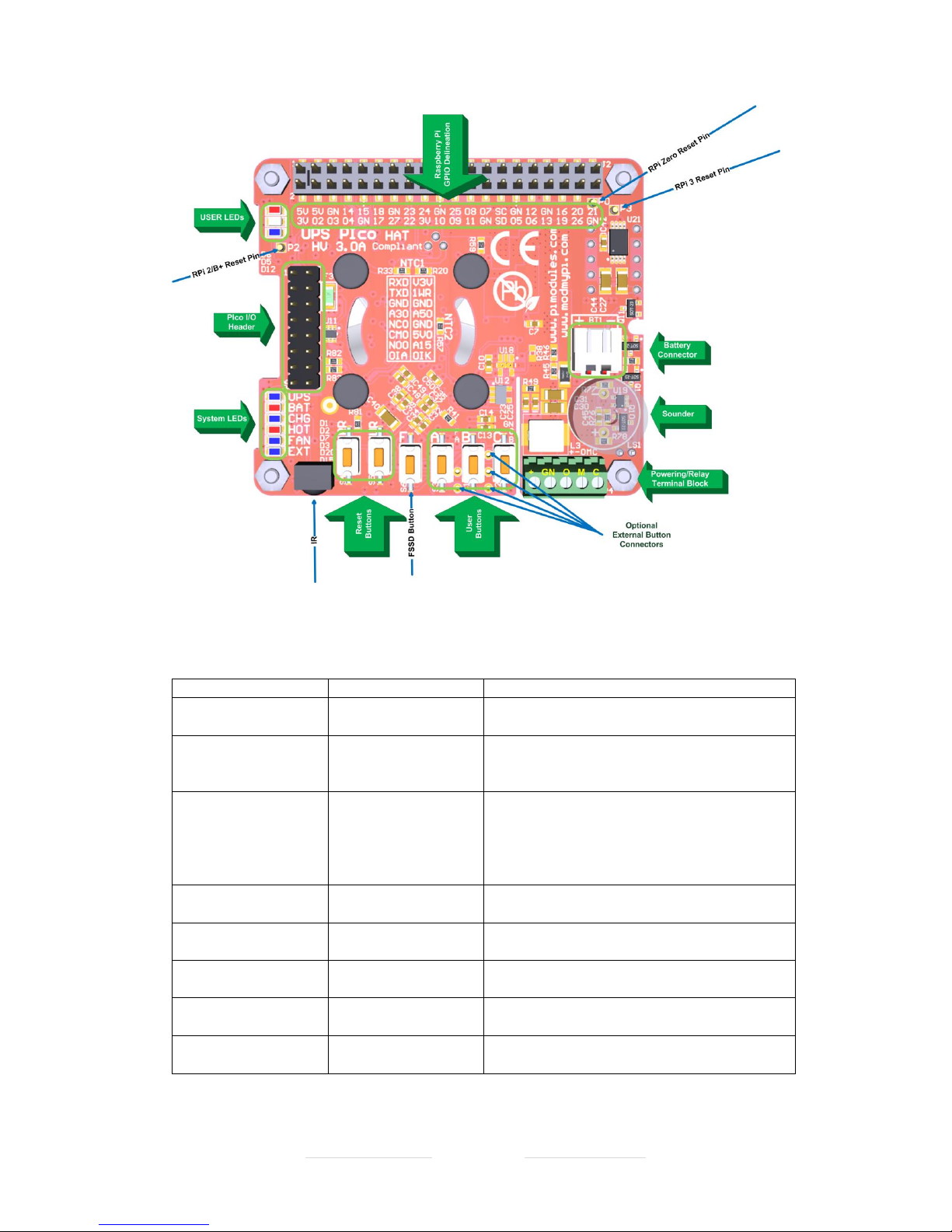
On each of UPS PIco HV3.0 are plenty of I/Os other User Interfaces (Keys, Sounder, etc). The
below pictures show each version I/Os.
Figure 1 UPS PIco HV3.0A Stack
UPS PIco HV3.0A Firmware Code 040 Print Date 18.08.2017
Designed and Manufactured by PiModules and ModMyPi
www.pimodules.com www.modmypi.com
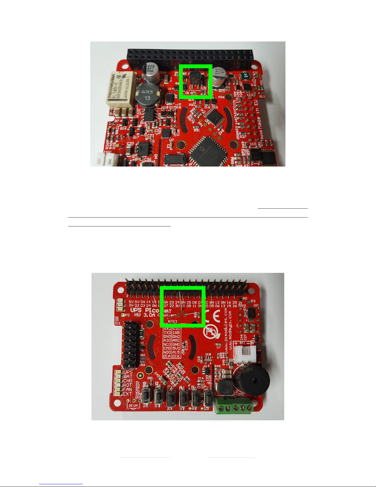
Figure 2 UPS PIco HV3.0A Stack Plus
Interface
Name on PCB
Functionality
40 Pin SMD Connector
with delineation
J2 (Black one placed on
the bottom side)
Used for Pass Through the Stack or Top End Connector.
Delineation helps users to find a proper GPIO if needed
User LEDs
None - (just 3 LEDs) placed
on the left-up corner of
PCB
3 color LEDs (Blue, Red, Green) accessed via I2C used for
user applications
Gold Pin (POGO pin)
P0, P2, P3
Used for hardware reset of the Raspberry Pi®, each
place is specified by the number, therefore:
P0 – means Raspberry Pi® ZERO
P2 – means Raspberry Pi® 2
P3 – means Raspberry Pi® 3
On Board Temperature
Sensor 1
NTC 1
Used for PCB temperature measure, as also as an
indicator of the environment temperature
On Board Temperature
Sensor 2
NTC 2
Used by Battery Charger to control the charging process
automatically (only in version Plus)
PIco I/O 16 pin (2x8)
header
none
Used for various I/O handled by UPS PIco HV3.0,
detailed described in next chapters
Bi-stable Relay
None - (right up corner –
on bottom side)
Bi-stable Relay soldered on bottom, used only for
various user applications
Battery Connector
BAT1
Battery connector, here should be plug in the battery
(any type or size)

UPS PIco HV3.0A Firmware Code 040 Print Date 18.08.2017
Designed and Manufactured by PiModules and ModMyPi
www.pimodules.com www.modmypi.com
System LEDs
UPS, BAT, CHG, HOT, FAN,
EXT
System LEDs used by UPS PIco HV3.0 for messaging to
the user on various conditions. Detailed described on
next chapters
Sounder
None (inside of circle, just
marked ‘+’ and ‘-‘ for
soldering)
Used for Sound Generation on various UPS PIco HV3.0
conditions or user applications
Infra-Red Receiver
IR U4
If soldered, then interface the Raspberry Pi® with IR
receiver, used for the any IR application
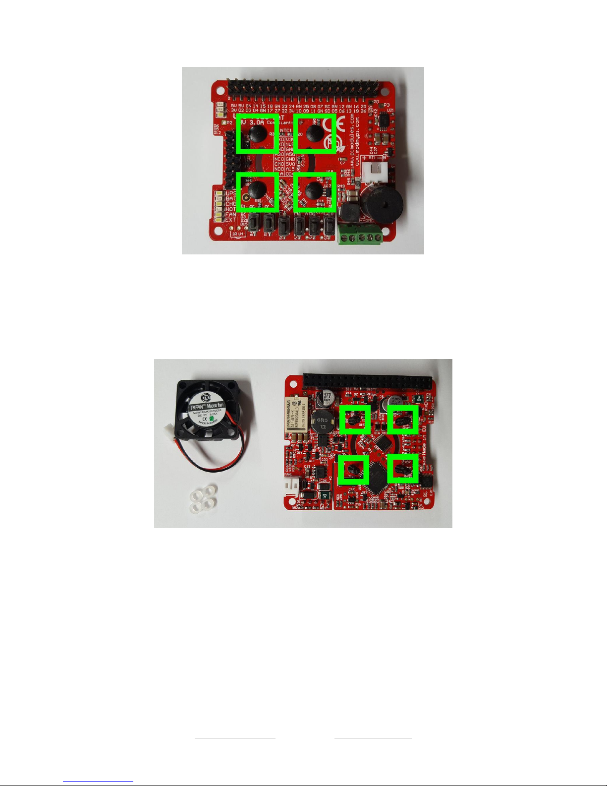
Hardware Reset Buttons
Buttons RR and UR
Hardware Reset Buttons:
RR – Raspberry Pi® Hardware Reset
UR – UPS PIco HV3.0 hardware Reset
FSSD Button
Button F
File Safe Shut Down Button – detailed description is in
next chapters
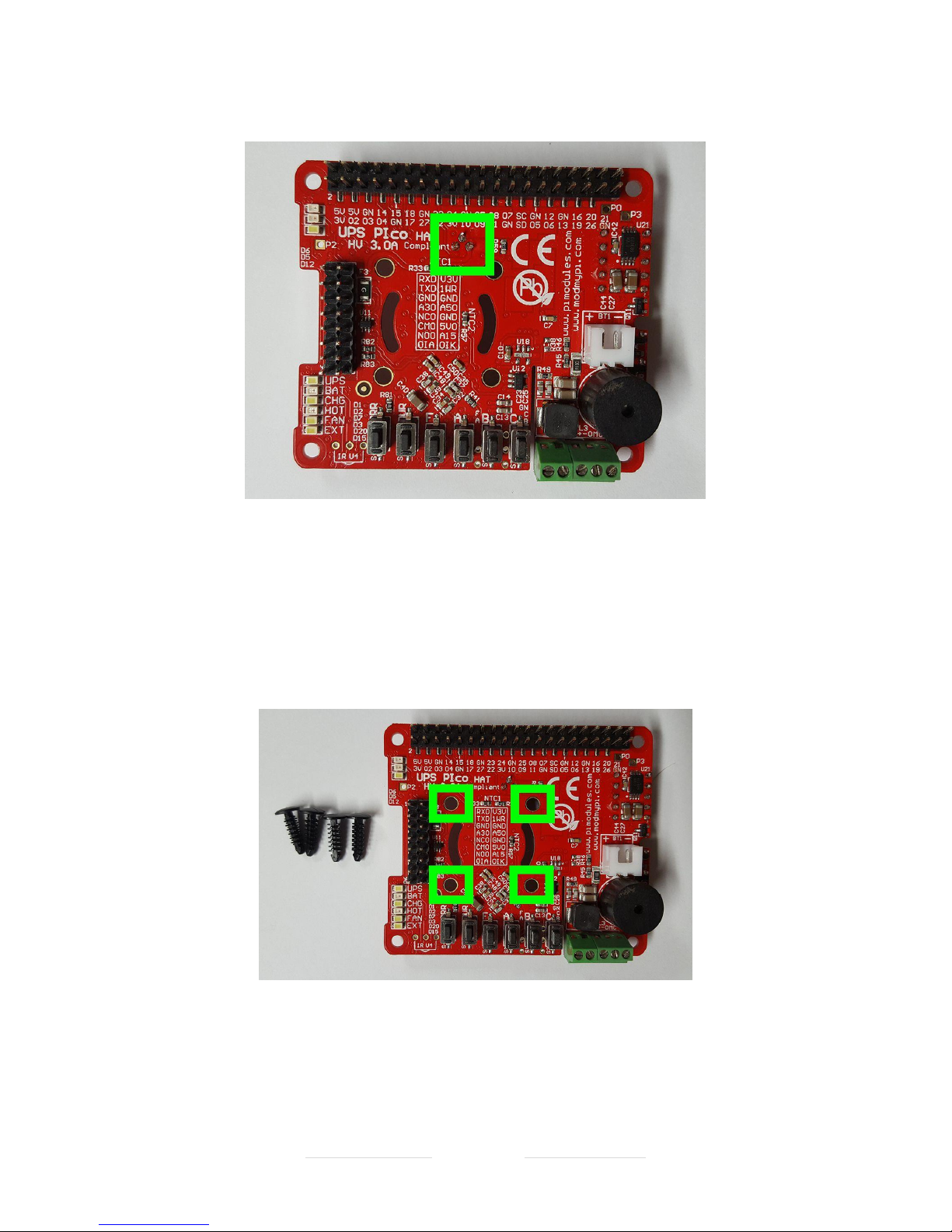
User Application Buttons
Buttons A, B, C
Buttons used for User Applications
Cable extensions for the
listed Buttons
Holes (THT pads): F, A, B,
C, G
Used for cable extensions of the following buttons if
user like to have external buttons i.e. screwed
externally on the case:
F – FSSD
A – Button
B – Button
C – Button
G – GND for buttons
Extended Power Supply
(7-28)
+, GND
Extended Power Supply (7-28) for version UPS PIco
HV3.0 Plus
Bi-Stable Relay contacts
1st set
O, M, C
Contacts for the Bi-Stable Relay (1st set)
O – Opened when Relay is Reset
M – Common
C – Closed when Relay is Reset
Connector for the FAN
LS1
Used to connect FAN when mounted the FAN kit (placed
on bottom)
Table 5 UPS PIco HV3.0A Interfaces

UPS PIco HV3.0A Firmware Code 040 Print Date 18.08.2017
Designed and Manufactured by PiModules and ModMyPi
www.pimodules.com www.modmypi.com
Hardware Interfacing/Interaction with Raspberry Pi®
The UPS PIco HV3.0A HAT module is plug on the top of the Raspberry Pi® micro-computer. It
is using the GPIOs for interaction with it as also dedicated software installed on the Raspberry
Pi® - called Daemons. Only few GPIOs are mandatory to have system cooperative with the
Raspberry Pi®, all others are optional and can be used only if needed. Detailed specifications
of them are listed below.
Figure 3 UPS PIco HV3.0A GPIO Used Pins

UPS PIco HV3.0A Firmware Code 040 Print Date 18.08.2017
Designed and Manufactured by PiModules and ModMyPi
www.pimodules.com www.modmypi.com
GPIO (Pin #)
Activity
Functionality
5V – #02, #03 – marked Orange
Powering 5V
Used for monitoring of 5V and when
absent the Raspberry Pi® system is
powered via it. Protected by ZVD
circuit and PPTC fuse of 2.6A
Ground - #06, #14, #20, #30, #34,
#09, #25 - marked Grey
System Ground
System Ground connected to the
Raspberry Pi® Ground
TXD0 and RXD0 – GPIO14 and
GPIO15 – #08, #10 – marked Yellow
Serial Connection to Raspberry Pi ®
Used for System Monitoring, or
firmware uploading – default is HiZ
(disconnected from the GPIOs), only
of user activate them are connected
to the GPIOs. During boot loading
process are automatically
connected, and after that
disconnected
IR Input – GPIO18 – #12 – marked
Yellow
Used only if IR soldered on their
place on the UPS PIco HV3.0
Only if IR is soldered this GPIO18 is
valid, all other cases are HiZ.
ID_SC – #28 – marked Yellow
Used for the HAT EEPROM
Used for the HAT EEPROM
I2C – SDA – GPIO02 Used as I2C SDA
– #03 – marked as Yellow
Used as I2C SDA
Used as I2C SDA for communication
with Raspberry Pi®
I2C – SCL – GPIO03 Used as I2C SDA
– #05 – marked as Yellow
Used as I2C SCL
Used as I2C SCL for communication
with Raspberry Pi®
GPIO27 – #13 – marked as Yellow
Used as Pulse Train send by UPS
PIco HV3.0 to the Raspberry Pi®
Used as Pulse train to fire Daemons
Interrupt in the Raspberry Pi®. This
functionality allows PIco to
recognize if Raspberry Pi is shutting
down, or running properly
GPIO22– #15 – marked as Yellow
Used as Pulse Train Response from
the Raspberry Pi® to the UPS PIco
HV3.0
Used as Pulse train to fire Interrupts
in the UPS PIco HV3.0 confirming
response of the Raspberry Pi®, as
also to shut down the Raspberry Pi®.
ID_SD – #27 – marked Yellow
Used for the HAT EEPROM
Used for the HAT EEPROM
Table 6 UPS PIco HV3.0A GPIO Usage
UPS PIco HV3.0A Firmware Code 040 Print Date 18.08.2017
Designed and Manufactured by PiModules and ModMyPi
www.pimodules.com www.modmypi.com
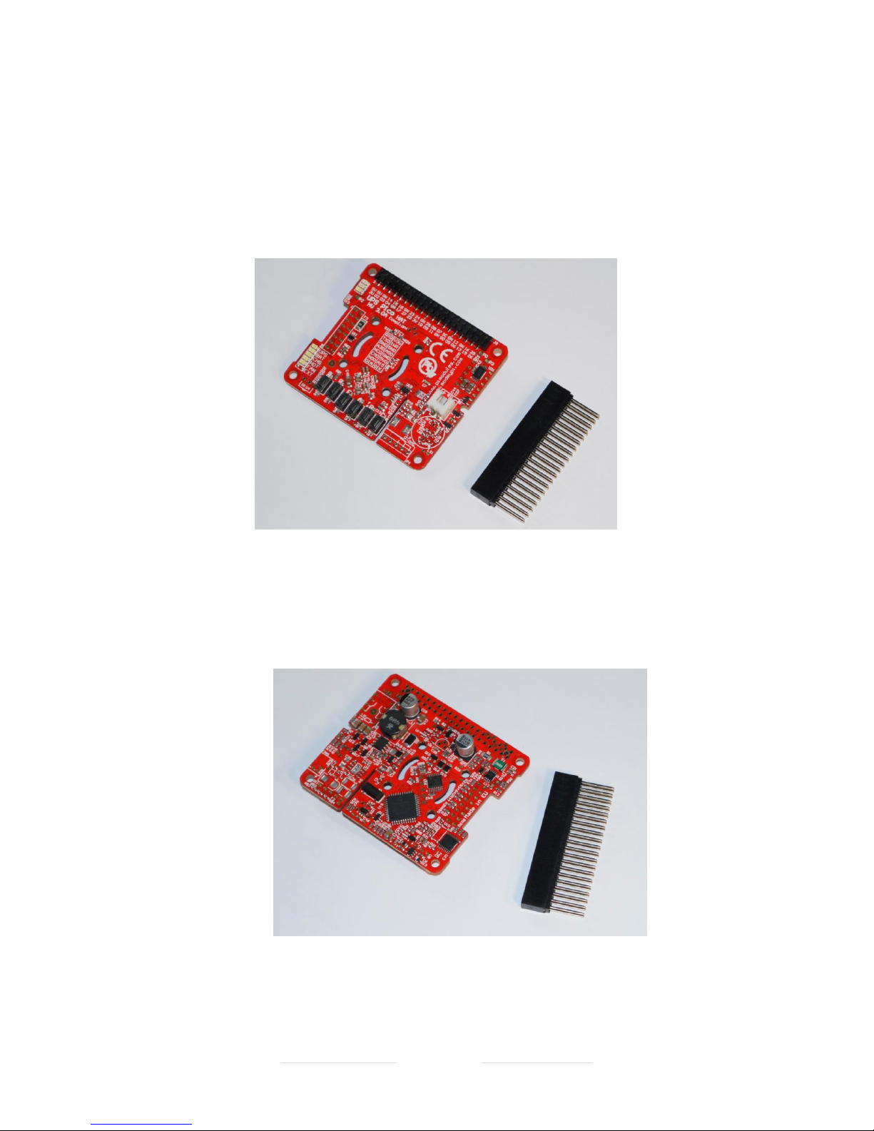
Assembly of the THT 40 Pins (2x20) connector
Ensure that you have prepared the Stack or TopEnd THT Connector. To properly pass through
the THT connector please follow below instructions:
• Prepare your UPS PIco HV3.0 HAT, and make sure that the black SMD 40 pins
connector is available
Figure 4 UPS PIco HV3.0 and 40 THT Stack Header
• Put your UPS PIco HV3.0 HAT upside down, and make sure that the black SMD 40 pins
connector is touching the table
Figure 5 UPS PIco HV3.0 and 40 THT Stack Header bottom side
• Apply the THT 40 Pins connector carefully though the holes on the UPS PIco HV3.0
HAT SMD. Apply pressure to the connector making sure you have placed the PCB on
UPS PIco HV3.0A Firmware Code 040 Print Date 18.08.2017
Designed and Manufactured by PiModules and ModMyPi
www.pimodules.com www.modmypi.com
something stable, like a table, so the connector can easily fit when it’s applied with
pressure.
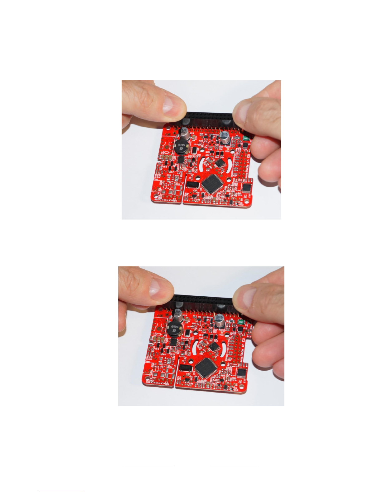
Figure 6 UPS PIco HV3.0 passing the 40 Pins THT connector
• Press the THT 40 Pins connector on the plastic side to complete pass its pins trough,
until end of them reaches the bottom of the PCB
Figure 7 UPS PIco HV3.0 partially passed the 40 Pins THT connector
• Put the PCB and the semi passed connector on the opposite side (this time on the
proper one) and then press the PCB on the connector side slowly and carefully until
UPS PIco HV3.0A Firmware Code 040 Print Date 18.08.2017
Designed and Manufactured by PiModules and ModMyPi
www.pimodules.com www.modmypi.com
the complete pins pass through, always pressing only the SMD connector and not the
PCB itself.
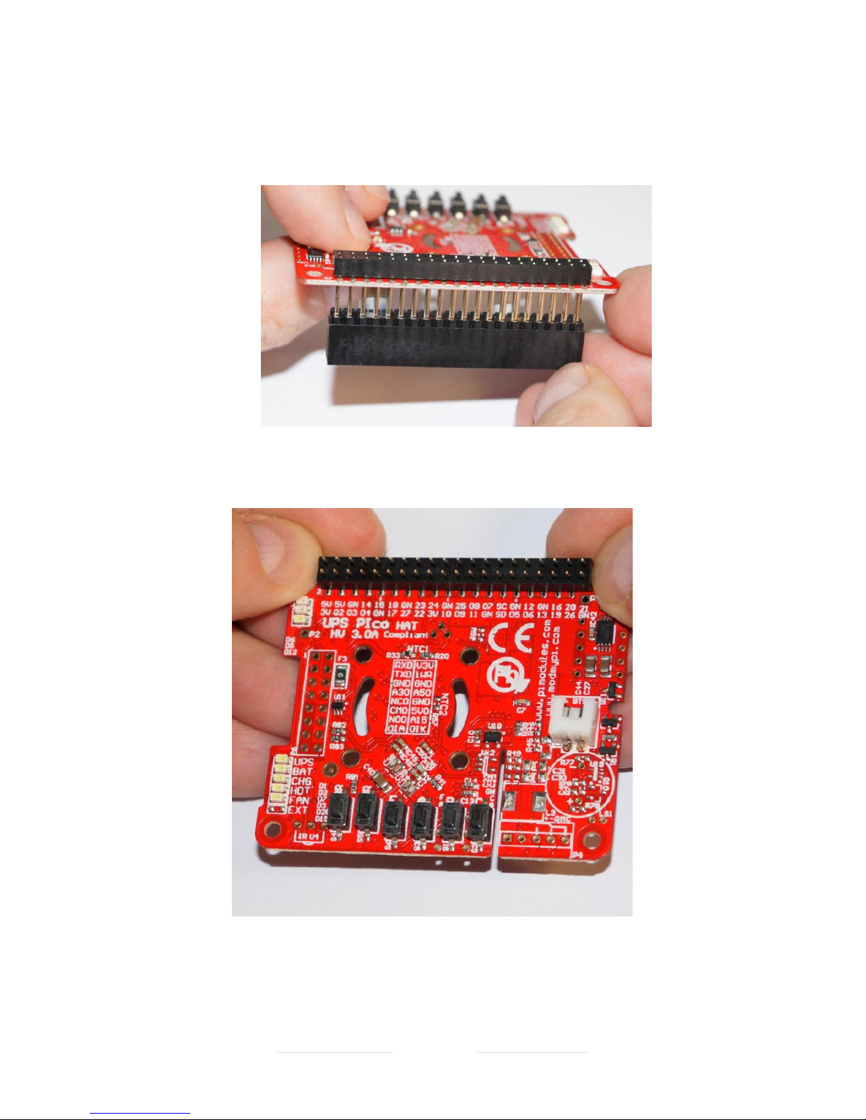
Figure 8 UPS PIco HV3.0 partially passed the 40 Pins THT connector side view
Figure 9 Figure 8 UPS PIco HV3.0 partially passed the 40 Pins THT connector top view

UPS PIco HV3.0A Firmware Code 040 Print Date 18.08.2017
Designed and Manufactured by PiModules and ModMyPi
www.pimodules.com www.modmypi.com
Figure 10 Figure 8 UPS PIco HV3.0 full passed the 40 Pins THT connector side view
Assembling the THT 40 pin Connector for the TopEnd Version is the same, the only difference
is that the top pins does not exist.
If you would like to install the PIco FAN Kit, please do so now following the
instructions below. It is not mandatory to install the fan kit now, but it will
enable full function of the UPS PIco HV3.0 HAT module.

UPS PIco HV3.0A Firmware Code 040 Print Date 18.08.2017
Designed and Manufactured by PiModules and ModMyPi
www.pimodules.com www.modmypi.com
Assembly of the FAN Kit
One of the add on available for the UPS PIco HV3.0 HAT is the FAN Kit. This Kit contains
everything what is needed to make it installed on the UPS PIco HV3.0 HAT module. There are:
• 1 x Ultra Low Noise DC FAN
• 1 x TO-90 Temperature sensor
• 4 x white 2mm spacers
• 4 x plastic tree clips
• 1 x 2mm connector for the Fan
These instructions will guide you through the installation of the TO92 and FAN.
Figure 11 FAN Kit Contents

UPS PIco HV3.0A Firmware Code 040 Print Date 18.08.2017
Designed and Manufactured by PiModules and ModMyPi
www.pimodules.com www.modmypi.com
Figure 12 2mm FAN connector placement
Start by soldering the FAN 2mm connector to the UPS PIco HV3.0 HAT PCB
Please make sure that before soldering of the 2mm connector, the sounder has been
soldered. If not, please solder first the sounder and after that the FAN connector.
Figure 13 Soldered 2mm FAN connector

UPS PIco HV3.0A Firmware Code 040 Print Date 18.08.2017
Designed and Manufactured by PiModules and ModMyPi
www.pimodules.com www.modmypi.com
Figure 14 2mm connector on the top side of PCB after soldering
After soldering of the 2mm connector, please cut the outstanding legs.
Figure 15 Temperature Sensor fitment place
Next, we'll solder on the TO92 Temperature Sensor. Start by inserting the TO92 into the 3
through holes on the PCB.
UPS PIco HV3.0A Firmware Code 040 Print Date 18.08.2017
Designed and Manufactured by PiModules and ModMyPi
www.pimodules.com www.modmypi.com
Figure 16 Temperature Sensor passed on the PCB
Flip the UPS PIco HV3.0 HAT PCB over, Put the PCB on the Raspberry Pi. Make sure that the
spacers have been screwed on the Raspberry Pi and keep the right distance between UPS PIco
HV3.0 HAT PCB and Raspberry Pi PCB. Press little bit the sensor legs down, to touch the
Raspberry Pi PCB and bend the legs out slightly to hold the TO92 in place. It is important to
have physical contact of the sensor with Raspberry Pi PCB or to be very close to it (0.5mm –
1mm), to have a proper measure of temperature.
Figure 17 Temperature Sensor legs before soldering
UPS PIco HV3.0A Firmware Code 040 Print Date 18.08.2017
Designed and Manufactured by PiModules and ModMyPi
www.pimodules.com www.modmypi.com
Solder and trim the legs, and cut the remain parts.
Figure 18 Soldered Temperature Sensor
Now it’s time to add the fan. Start by pressing the four studs through the fan mounting holes,
from the top of the UPS PIco HV3.0 HAT. Do it very carefully, and preferred before installed
the Gold-Plated Reset Pin (as when it is installed, it is easy to break it, when pressing them)
Figure 19 Preparation of the Plastic Tree Clips for FAN
UPS PIco HV3.0A Firmware Code 040 Print Date 18.08.2017
Designed and Manufactured by PiModules and ModMyPi
www.pimodules.com www.modmypi.com
Figure 20 Plastic Tree Clips mounted on the PCB ready for FAN assembly
Flip the UPS PIco HV3.0 HAT PCB over.
Figure 21 Plastic Tree Clips on the PCB Bottom side
Add a spacer to each of the studs. Finally, add the fan and connect the FAN wire up. The fan
blows air towards the label on the FAN. There are 2 ways to mount the FAN. If decided to have
this facing down the blow cold air directly onto the SoC of the Pi. It cools better the SoC
however collect more dust from outside. If you put on the opposite way (the label on the side
of the PCB) then it cools the whole PCB, and collect less dust.

UPS PIco HV3.0A Firmware Code 040 Print Date 18.08.2017
Designed and Manufactured by PiModules and ModMyPi
www.pimodules.com www.modmypi.com
Figure 22 Plastic Tree Clips on the PCB Bottom side with 2mm spacers passed
Figure 23 FAN placed on the UPS PIco HV3.0 PCB
When placing the FAN on the Plastic tree clips be very carefully to avoid damaging the FAN
propel when pressing it.

UPS PIco HV3.0A Firmware Code 040 Print Date 18.08.2017
Designed and Manufactured by PiModules and ModMyPi
www.pimodules.com www.modmypi.com
Assembly of the Buzzer (Sounder)
If you would like to use the buzzer, you can solder it on now. Ensure that this is
done with the correct polarity. Positive “+” on the board should match the positive
“+” on the buzzer. The soldering procedure is same for the High and Low (used in TopEnd
Version) profile buzzer.
Figure 24 Prepare the UPS PIco HV3.0 HAT and buzzer
Figure 25 Make sure to solder "+" of the buzzer to the proper place

UPS PIco HV3.0A Firmware Code 040 Print Date 18.08.2017
Designed and Manufactured by PiModules and ModMyPi
www.pimodules.com www.modmypi.com
Figure 26 Flip upside down the PCB and colder the pins, then cut the outstanding legs
If you would like to install the Gold-Plated Reset Pin, please do so now following the
instructions below. It is not mandatory to install the pin now, but it will
enable full function of the UPS PIco HV3.0 HAT module. However, it can be installed in next
stages.
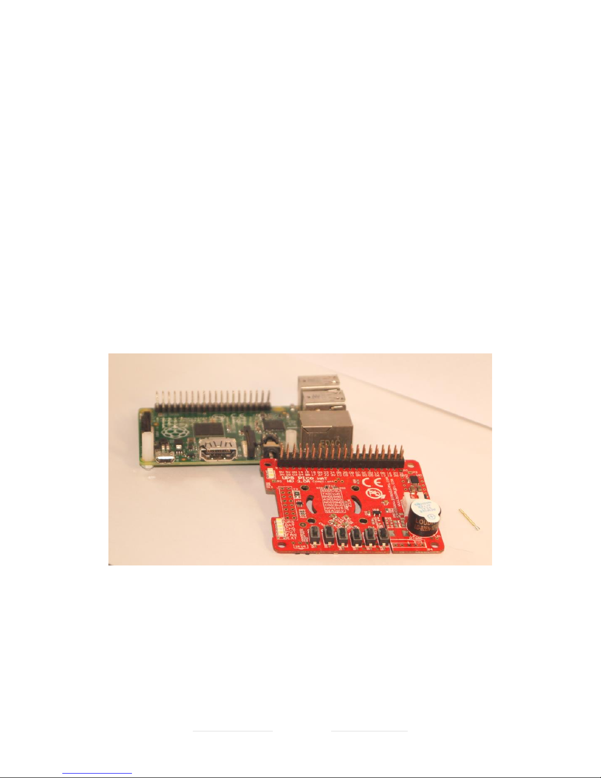
UPS PIco HV3.0A Firmware Code 040 Print Date 18.08.2017
Designed and Manufactured by PiModules and ModMyPi
www.pimodules.com www.modmypi.com
Assembly of the Gold-Plated Hardware Reset Pin (POGO Pin)
The Gold Plated Hardware Reset Pin (POGO Pin) is used to provide various additional
functionalities to the UPS PIco HV3.0 HAT. It is not necessary, however strongly recomened
as additional functionalities covered by it make the UPS PIco HV3.0 HAT system more cooperative. It is used with the following functionalities already implemented in the UPS PIco
HV3.0 HAT, they are:
• Button for Hardware Reset of Raspberry Pi®
• Watch Dog ("Still Alive?") functionality - Automatically Resetting (Restarting) of the
Raspberry Pi® when hung-up
• Resetting (Restarting) of the Raspberry Pi® when cable power returns during shutting
down process.
There is a very simple hand work needed to solder this pin to the Raspberry Pi®
Place on your desk the Raspberry Pi® the UPS PIco HV3.0 HAT and the Gold-Plated Reset Pin.
Figure 27 Raspberry Pi, UPS PIco HV3.0 HAT, and Gold-Plated Reset Pin
Drag on the Gold Plated Reset Pin through the hole on the UPS PIco HV3.0 HAT as shown in
the pictures below. Take care to drag on the right direction. Select the proper hole for your
Raspberry Pi ® model (P0, P2, P3) marked on the UPS PIco HV3.0 HAT PCB (Related to
Raspberry Pi® models Zero, 2 and 3)

UPS PIco HV3.0A Firmware Code 040 Print Date 18.08.2017
Designed and Manufactured by PiModules and ModMyPi
www.pimodules.com www.modmypi.com
Drag on the Gold Plated Reset Pin on the direction as shown on the below picture.
Figure 28 Gold-Plated Reset Pin on the place RPi3
Make sure to screw the poper spacers on the side where HDMI connector of the Raspberry
Pi® (on the oposite side of the 40 pin connector and screw them). This will ensure that the
distance between UPS PIco HV3.0 HAT and Raspberry Pi® is proper and provide a resistance
when UPS PIco HV3.0 HAT buttons are pressed.

UPS PIco HV3.0A Firmware Code 040 Print Date 18.08.2017
Designed and Manufactured by PiModules and ModMyPi
www.pimodules.com www.modmypi.com
Figure 29 Spacers screwed on their places
Put the UPS PIco HV3.0 HAT on the Raspberry Pi®, and take care to center the head of the
Gold Plated Reset Pin to the center of the RUN square pad hole.
Figure 30 UPS PIco HV3.0 on the Raspberry Pi with Gold-Plated Reset Pin
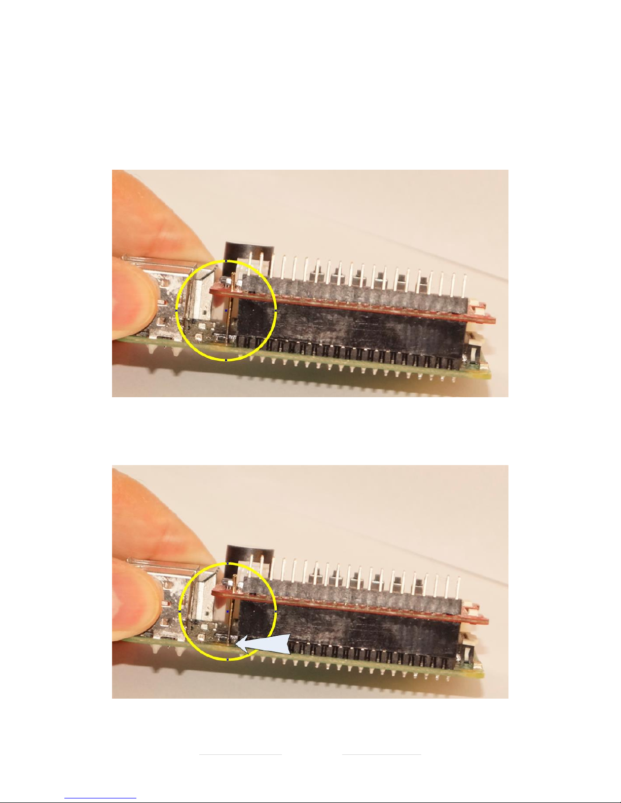
UPS PIco HV3.0A Firmware Code 040 Print Date 18.08.2017
Designed and Manufactured by PiModules and ModMyPi
www.pimodules.com www.modmypi.com
Check it, by pressing the pin on the Top. Then, using a soldering tool, solder the Gold-Plated
Reset Pin on the top of the PCB only. Take care to heat up properly the pin before you will
add the tin. After soldering it will look like in the picture below. Make sure that the Gold-
Plated Reset Pin after soldering touches properly the RUN on the Raspberry Pi®.
Figure 31 The Gold-Plated Reset Pin must point exactly on the hole of the RUN pad
Figure 32 Pointing exactly on the hole of the RUN pad
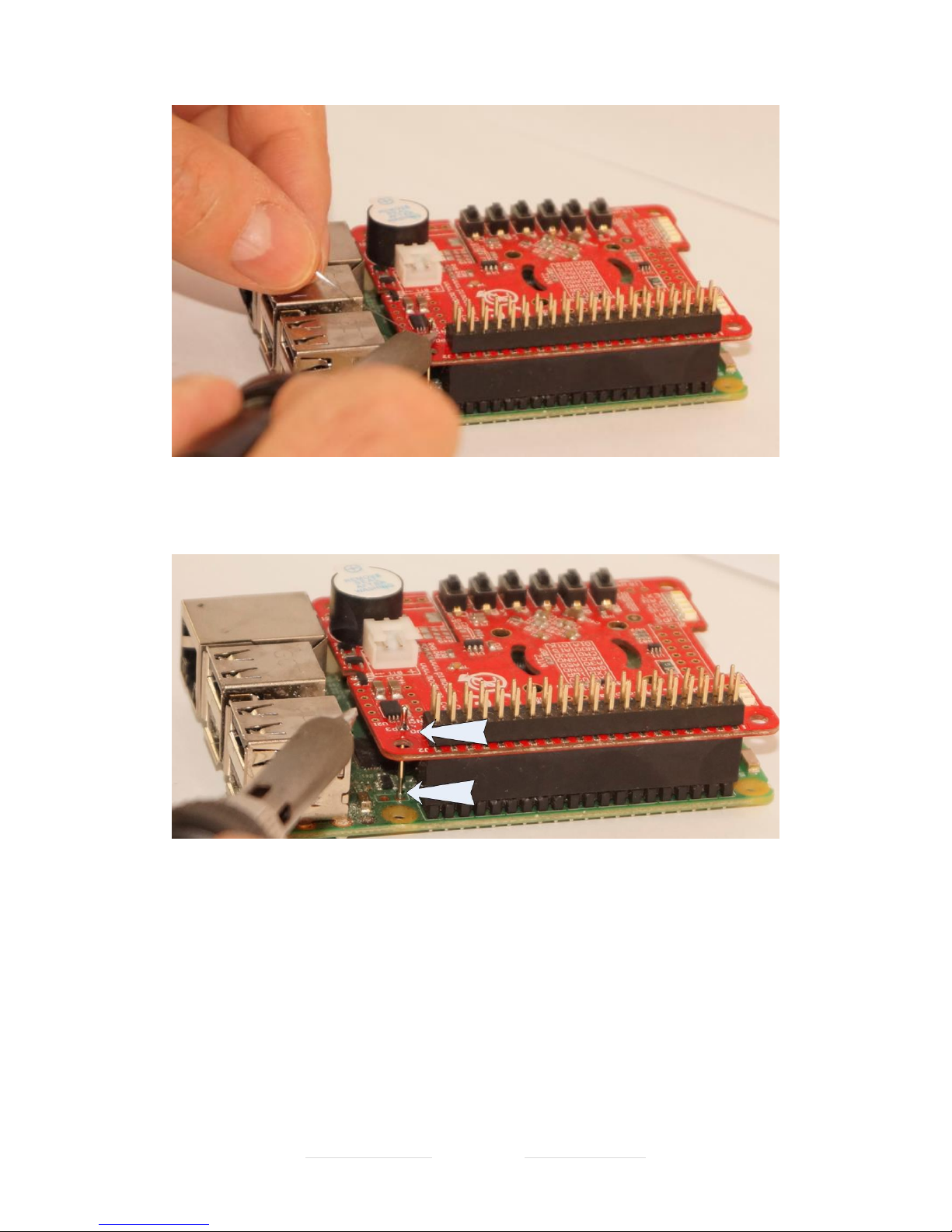
UPS PIco HV3.0A Firmware Code 040 Print Date 18.08.2017
Designed and Manufactured by PiModules and ModMyPi
www.pimodules.com www.modmypi.com
Figure 33 Soldering the Gold-Plated Reset Pin on the PIco
Figure 34 Soldered Gold-Plated Reset Pin is touching exactly the RUN pad
Then to make Gold Plated Reset Pin internal spring working, you need to re-solder it by
pressing down for about 1.5 – 2 mm. Press it down with screw driver and heat up with a
soldering tool. Then remove the soldering tool, keeping pressing the pin down. After about 5
seconds, you can put out the screw driver.
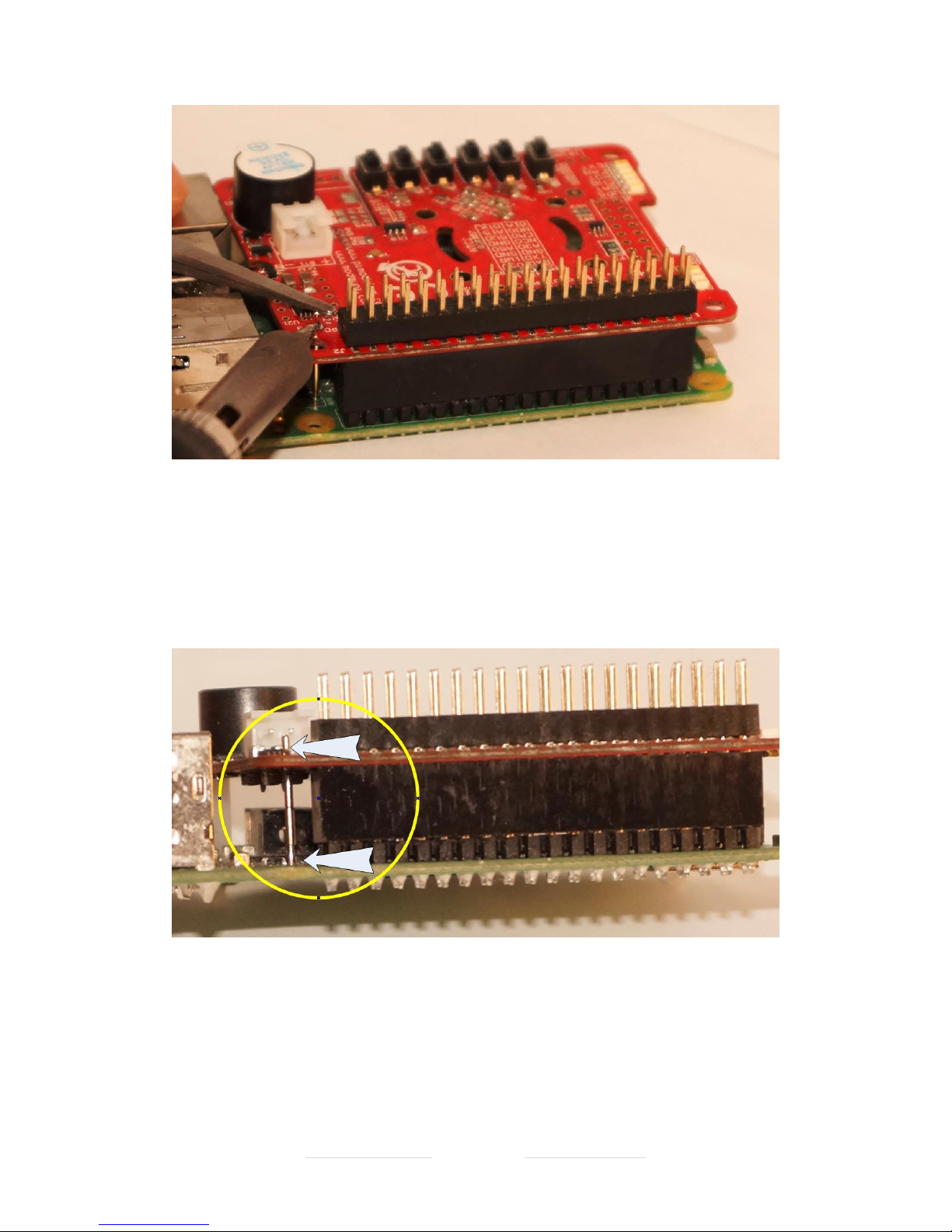
UPS PIco HV3.0A Firmware Code 040 Print Date 18.08.2017
Designed and Manufactured by PiModules and ModMyPi
www.pimodules.com www.modmypi.com
Figure 35 Heating and pressing of the Gold-Plated Reset Pin
You will make the Gold-Plated Reset Pin ready.
Figure 36 Gold-Plated Reset Pin properly soldered
To test it, make Raspberry Pi® working and reset it by pressing the R button on the UPS PIco
HV3.0 HAT.
More advanced usage of the Gold Plated Reset Pin is described in another chapter.

UPS PIco HV3.0A Firmware Code 040 Print Date 18.08.2017
Designed and Manufactured by PiModules and ModMyPi
www.pimodules.com www.modmypi.com
Assembly of the Bi-Stable Relay
If you would like to install the Bi-Stable Relay kit, please do so now following the
instructions below. It is not mandatory to install the Bi-Stable Relay now, but it will enable full
function of the UPS PIco HV3.0 HAT module. User need to follow the below steps when
assembling it to the UPS PIco HV3.0 HAT PCB.
Prepare the UPS PIco HV3.0 PCB, Bi-Stable Relay and 3 ways Terminal Block
Figure 37 Ready for assembly UPS PIco HV3.0 HAT, Bi-Stable Relay and Terminal Block
Make sure that marker of the Bi Stable Relay (white bold line) and on PCB are on the same
direction. It is very important because if Bi Stable Relay will be soldered in a wrong way, it is
not possible (ultra-difficult) to de-solder it again and correct
Figure 38 UPS PIco HV3.0 on Bottom Side, and Bi-Stable Relay

UPS PIco HV3.0A Firmware Code 040 Print Date 18.08.2017
Designed and Manufactured by PiModules and ModMyPi
www.pimodules.com www.modmypi.com
Put the Bi Stable Relay Pins trough the holes
Figure 39 Put the Bi-Stable Relay on the PCB
Put the PCB with Relay to the opposite side and solder only one pin. It is very important to
solder only one pin, as if you made a mistake it will be easy to correct it.
Figure 40 Soldering of one pin of the Bi-Stable Relay
Then make sure that everything (after double checking) are OK, and proceed with soldering
of all other Pins.

UPS PIco HV3.0A Firmware Code 040 Print Date 18.08.2017
Designed and Manufactured by PiModules and ModMyPi
www.pimodules.com www.modmypi.com
Figure 41 Soldered one pin of the Bi-Stable Relay
Solder all the rest of Bi-Stable Relay very carefully to avoid any short-cut with other near
placed components.
Figure 42 Completely Soldered Bi-Stable Relay
After completing of the soldering, cut the outstanding over the PCB pins (very carefully – PCB
is very density!!!)

UPS PIco HV3.0A Firmware Code 040 Print Date 18.08.2017
Designed and Manufactured by PiModules and ModMyPi
www.pimodules.com www.modmypi.com
Figure 43 Cutting of the outstanding pion of the soldering Bi-Stable Relay
Prepare the 3 ways terminal block. Make sure that cables holes are in the proper side (looking
outside)
Figure 44 Terminal Blocks for the Bi-Stable

UPS PIco HV3.0A Firmware Code 040 Print Date 18.08.2017
Designed and Manufactured by PiModules and ModMyPi
www.pimodules.com www.modmypi.com
Pass the Terminal Block through the holes. Make sure that Terminal Blocks cables holes looks
to the outside side.
Figure 45 Terminal Block on the proper side
Figure 46 Soldered Terminal Blocks
Solder Terminal Block Pins and cut the outstanding legs over the PCB, be very careful with
other components placed near to them (SMD Resistors).

UPS PIco HV3.0A Firmware Code 040 Print Date 18.08.2017
Designed and Manufactured by PiModules and ModMyPi
www.pimodules.com www.modmypi.com
Figure 47 Cutting of the Terminal Block outstanding legs
Power Supply Unit Recommendations
Please ensure that you are using a good quality Power Supply Unit available for powering of
the Raspberry Pi and UPS PIco HV3.0 HAT. A PSU 5V@2.5A is recommended, however for
more advanced applications 5V@3.0A PSU is preferred. This will ensure that there is enough
current to recharge the PIco’s battery. Low quality PSUs, or PSUs with bad quality of supply
cables cause a voltage drops on the Raspberry Pi® 5V GPIOs that are recognized by the PIco
and force a wrong functionality. It is also mandatory to have good quality micro USB powering
cable. Please avoid PSUs that use dual USB connectors as there are double voltage drops on
both USB connections (micro USB, and USB socket).
Once you have all parts correctly installed, we’re ready to proceed with software installation

UPS PIco HV3.0A Firmware Code 040 Print Date 18.08.2017
Designed and Manufactured by PiModules and ModMyPi
www.pimodules.com www.modmypi.com
Software Setup for UPS PIco HV30 Stack/TopEnd/Plus
There are a few very simple steps than need to be followed to setup the software. In any case
if user cannot follow these guides, a ready SD image (8GB) is available on our forum, always
with the latest NOOBS, with all software procedures installed. It can be used also as a running
example on a separate SD card for debugging purposes.
There is no need to have placed the UPS PIco HV3.0 HAT on top of the Raspberry Pi® when
installing the software, however can be also placed on top. The presence of the UPS PIco
HV3.0 HAT does not affect software installation.
The software installation procedure consists the following steps that need to be executed
• Operating System Installation (Raspbian)
• Activation of I/Os (i.e. I
2
C) as also some libraries installation
• Daemons Installation
• RTC Installation
• If needed in the future, firmware updates installation (this operation need to have
installed UPS PIco HV3.0 HAT hardware)
Installation of the Operating System (Raspbian)
Please download and proceed with installation of the latest NOOBS or install a separate
RASPBIAN on your SD card. If you like you can use also a ready to use installed image that can
be downloaded directly from our forum. It consists always the latest NOOBS installed with all
stuff needed included. There is also an image restore program included in the ZIP file. It can
be downloaded from the following link.
http://www.forum.pimodules.com/viewtopic.php?f=30&t=4126
The installed software for interaction with the Raspberry Pi, is using the GPIOs GPIO_GEN27
and GPIO_GEN22. These GPIOs are used to send and receive pulse train to/from the Raspberry
Pi. It is also used to initiate the shutdown procedure when/if it is needed. The Daemons are
monitoring these GPIOs and fire-up and interrupt on the Raspberry Pi side. This approach is
very flexible and does guarantee that interaction even if huge files are copied and Raspberry
Pi is ultra-busy with other tasks.
Installation Procedure of Daemons and email broadcasting System
1. Install Raspberry Pi Operation System (i.e. NOOBs)

UPS PIco HV3.0A Firmware Code 040 Print Date 18.08.2017
Designed and Manufactured by PiModules and ModMyPi
www.pimodules.com www.modmypi.com
2. Enable the I
2
C
3. Ensure that Python is installed and updated, by using the following command
sudo apt-get install python-rpi.gpio
4. Ensure to run below line
sudo apt-get -y install git python-dev python-serial python-smbus
python-jinja2 python-xmltodict python-psutil python-pip
(Take note of the line-wrapping above, it should all be on one line)
5. Note that some of the above can also be install with pip as below:
sudo pip install jinja2
sudo pip install xmltodict
(Obviously after python-pip has been installed)
6. Clone Raspberry Pi daemons and email broadcasting system from the GitHub using
the following command
sudo git clone
7. Move to the required directories where software has been copied.
8. First to the email broadcasting system (package)
sudo cd PiModules/code/python/package
9. Then proceed with the installation of the email package software
sudo python setup.py install
more information about the package usage and details are available at
https://github.com/modmypi/PiModules
10. Second to the System Monitoring and File Safe Shutdown Daemons (picofssd)
cd ../upspico/picofssd
11. Then proceed with the installation of the picofssd daemons software
sudo python setup.py install

UPS PIco HV3.0A Firmware Code 040 Print Date 18.08.2017
Designed and Manufactured by PiModules and ModMyPi
www.pimodules.com www.modmypi.com
12. Once the script has been installed, it can be installed to the `SystemD` with the
following command
sudo systemctl enable picofssd.service
13. Now when the Pi is rebooted the daemon should start automatically.
The Daemons can be started and stopped in the usual way for SystemD:
sudo systemctl start picofssd.service
sudo systemctl stop picofssd.service
Important Notices:
1. Both PIco packages must be installed even if not used.
2. It is very important to start/stop the Daemons Service when doing Hardware
Reset of the PIco HV3.0 to avoid undefined situations with pulse train recognition
procedure by the system. Resetting the PIco with Not Stopped the Daemon
Service can cause an unexpected system shutdown (however without card
corruption - system will just safety shutdown).

UPS PIco HV3.0A Firmware Code 040 Print Date 18.08.2017
Designed and Manufactured by PiModules and ModMyPi
www.pimodules.com www.modmypi.com
Installation Procedure of the UPS PIco HV3.0 Hardware RTC
1. Ensure to run below line
sudo apt-get -y install i2c-tools
2. Edit by running the following line
sudo nano /etc/modules
and check, make sure to have the following items in the file and add what is
missing:
i2c-bcm2708
i2c-dev
rtc-ds1307
3. Edit by running the following line
sudo nano /boot/config.txt
4. and add the following to this file:
enable_uart=1
dtoverlay=i2c-rtc,ds1307
5. Edit by running the following line
sudo nano /etc/rc.local
6. and add the following line before “exit 0”
sleep 4; hwclock -s &
7. Reboot system by
sudo reboot
8. Remove the fake-hwclock which interferes with the RTC hwclock
sudo apt-get -y remove fake-hwclock
sudo update-rc.d -f fake-hwclock remove
9. Run
sudo nano /lib/udev/hwclock-set

UPS PIco HV3.0A Firmware Code 040 Print Date 18.08.2017
Designed and Manufactured by PiModules and ModMyPi
www.pimodules.com www.modmypi.com
10. and comment out these three lines:
#if [ -e /run/systemd/system] ; then
# exit 0
#fi
11. Run date to verify the time is correct.
12. Plug in Ethernet or WiFi (if not plugged before) to let the Pi sync the right time
from the Internet. Once that's done, run:
sudo hwclock -w
13. to write the time, and another
sudo hwclock -r
13. to read the time
That's it! Next time you boot the time will automatically be synced from the RTC
module.
Automatic Installation Scripts
Two valuable users have been written an Automatic Installations Scripts that are
very useful. Users that prefer to make the installation easier using them can find
information here below:
1. Siewert Lameijer’s located at
http://www.forum.pimodules.com/viewtopic.php?f=27&t=4870
2. Crescendo Fang’s located at
http://www.forum.pimodules.com/viewtopic.php?f=27&t=3053

UPS PIco HV3.0A Firmware Code 040 Print Date 18.08.2017
Designed and Manufactured by PiModules and ModMyPi
www.pimodules.com www.modmypi.com
Bootloader Feature – keep the system up to date
UPS PIco HV3.0 A HAT is a very flexible hardware platform that offers a wide range of
features. Most of them are software programable. Therefore, during the time, new
versions with additional features are released. It is mandatory for the user, to have
the ability to upload the newest firmware version whenever it is released, to keep the
UPS PIco HV3.0 A HAT up to date. The firmware upload to the PIco HV3.0 A HAT is
done by running a small piece of software located in dedicated memory part in the
micro controller called boot sector. This memory part is protected from any erase, so
even if uploading of the new firmware procedure fails, this bootloader will never fail.
The execution (the invoking) of the bootloader can be done from a software level by
running of some dedicated commands, or manually by pressing of dedicated key
sequence. The bootloader is equipped with additional protection mechanism called
watch-dog, and if within 32 seconds from invoking of it system not start uploading the
new firmware, UPS PIco HV3.0 A HAT will be reset, and start execution of the old
already existing firmware. The bootloader functionality ensures that the UPS PIco
HV3.0 A HAT is up-to-date, and allows users to report various changes that can be
implemented on the user’s side. It is extremely useful functionality, and ensures that
the product has longevity.
As the bootloader uses the Raspberry Pi® Serial Port (RS232), it is mandatory to have
it free on the Raspberry Pi® (without any hardware occupying it). It is also important
that you ensure that there is no software using it. As well if minicom has been used,
please restart the Raspberry Pi, as minicom keeps the RS232 interface occupied.
When doing the firmware upload, it is also mandatory to have the system cable
powered (there is no UPS protection provided during that time) as also have stopped
the Daemons to avoid any undefined conditions with used GPIOs.

UPS PIco HV3.0A Firmware Code 040 Print Date 18.08.2017
Designed and Manufactured by PiModules and ModMyPi
www.pimodules.com www.modmypi.com
Firmware updates Procedure of the UPS PIco HV3.0 (on RPi3)
Serial Port disable Procedure
To disable serial communication over the UART long enough to do a Firmware update.
You need to do two things.
1. Run
sudo nano /boot/config.txt and add this line:
dtoverlay=pi3-disable-bt
2. Run
sudo systemctl disable hciuart
3. Run
sudo systemctl stop
4. Run
sudo systemctl disable
5. You could also disable the console by removing this line from /boot/cmdline.txt if
present, then reboot:
console=ttyAMA0,115200
As it has been written before the UPS PIco HV3.0 A HAT features an embedded serial
bootloader which allows users to update the unit’s firmware. The firmware can be
uploaded using a dedicated python script, called 9600_picofuHV3.0.py
It is mandatory to have previously installed python and I2C-tools on the Raspberry Pi.
You will install these during initial PIco setup outlined previously in this entity. Please
install smbus support for python to enable additional functionality. Simply run the
following command (with an internet connection):
sudo apt-get install python-smbus
The first task which is done by the UPS PIco HV3.0 A HAT after reset is to check if
bootloader has been requested. If not, then the rest of the firmware runs. Otherwise,
the UPS PIco HV3.0 A HAT lights the Orange User LED and waits for the firmware
upload from the Raspberry Pi ®, and when firmware starts uploading, change from
Orange User LED to Blue User LED.
There are two ways to invoke the bootloader mode and to upload the new firmware:
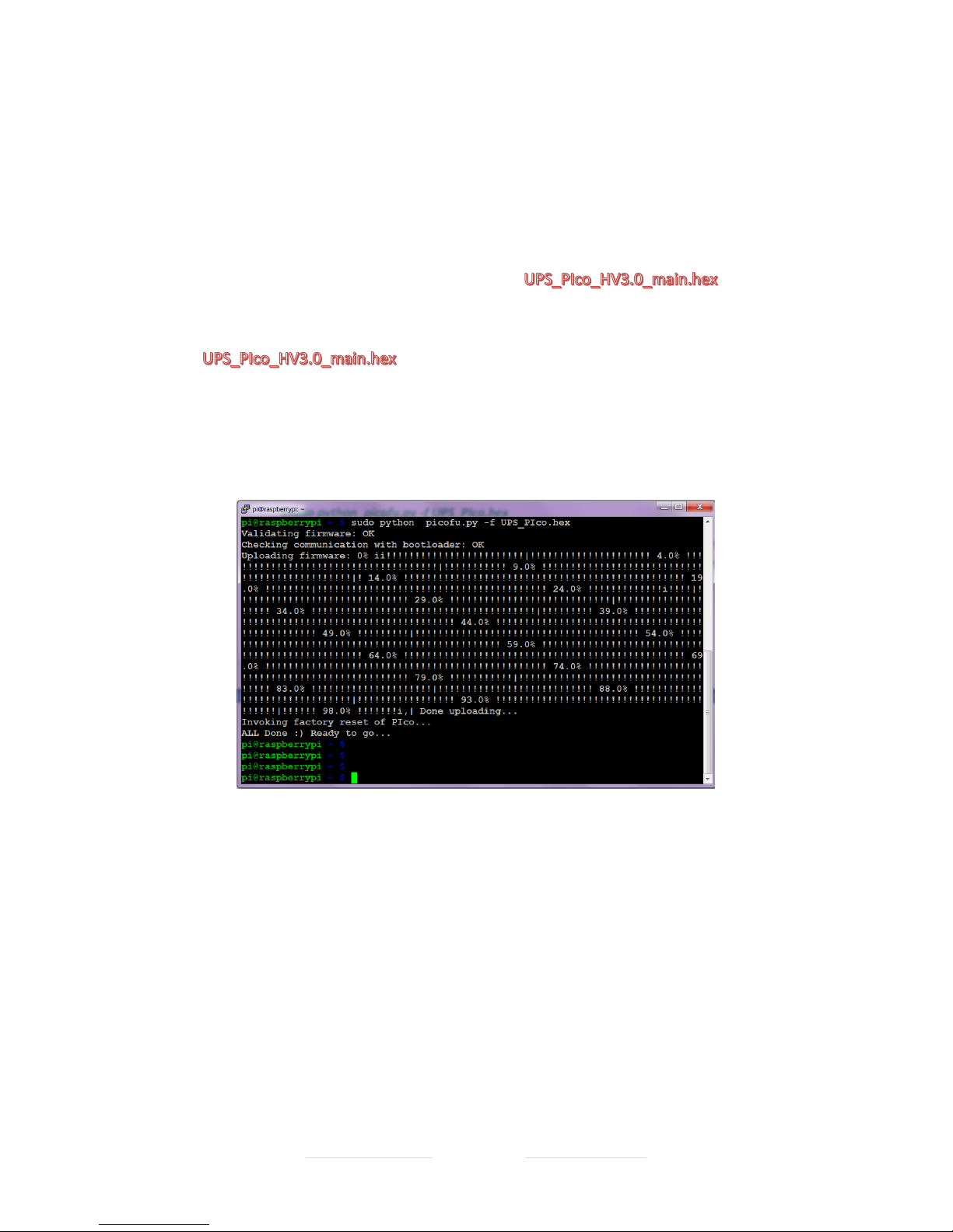
UPS PIco HV3.0A Firmware Code 040 Print Date 18.08.2017
Designed and Manufactured by PiModules and ModMyPi
www.pimodules.com www.modmypi.com
Automatic Bootloader Initiation
Remember to have system cable powered as during the boot loading procedure
system is not protected from power losses
The bootloader is invoked by running the following command line:
sudo i2cset -y 1 0x6b 0x00 0xff
sudo python 9600_picofuHV3.0.py -v -f
The should be replaced with the name of the last firmware
update, or the firmware you wish to use.
When firmware starts the upload procedure, the Orange User LED will have lit, and
then when firmware starts uploading the Blue User LED will lit and UPS LED will be
blinking.
Figure 48 SSH screen when firmware uploading
Once complete the system with output ALL Done :) Ready to go. . .
We would recommend that you now shutdown your Pi and UPS PIco HV3.0 A HAT
completely to ensure that all changes are integrated. Once you’ve rebooted your
system, you can check the UPS PiCo firmware version using the following command:
sudo i2cget -y 1 0x69 0x26
In this case the system should output 0xXX, signifying that the firmware has updated
correctly.

UPS PIco HV3.0A Firmware Code 040 Print Date 18.08.2017
Designed and Manufactured by PiModules and ModMyPi
www.pimodules.com www.modmypi.com
Manual Bootloader Initiation
For emergency reasons (i.e. faulty upload, upload of a wrong corrupted files etc.) The
UPS PIco HV3.0 A HAT has the ability to invoke the bootloader manually, via the onboard buttons. You can do this instead of using the automatic initiation outlined
above. However, user need to have physically access to the device, as needs to push
buttons.
It is very important to stop (before upload) and then start (after upload) the Daemons
Services when doing Hardware Reset of the PIco HV3.0 to avoid undefined situations
with pulse train recognition procedure by the system. Resetting the PIco with Not
Stopped the Daemon Service can cause an unexpected system shutdown (however
without card corruption). Please use the below command to stop the FSSD service
sudo systemctl stop picofssd.service
The following procedure needs to be followed:
• Press and hold the UR button
• Continue to hold the UR button, and press and hold the F button.
• Release the UR button, but keep holding the F button
• Release the F button
The Orange User LED will have lit, and system will be able to receive the firmware
update
Then write the following command on the Raspberry Pi command line
sudo python 9600_picofuHV3.0.py -v -f
The should be replaced with the name of the last firmware
update, or the firmware you wish to use.
If within 32 second after boot loader initiation the firmware is not start uploaded, the
UPS PIco HV3.0 will be reset to normal working conditions by internal Watch Dog
mechanism. This has been implemented for security reasons for remote firmware
upload.

UPS PIco HV3.0A Firmware Code 040 Print Date 18.08.2017
Designed and Manufactured by PiModules and ModMyPi
www.pimodules.com www.modmypi.com
Post-Firmware Update procedure
After firmware upload some steps are needed to return the system to previous state.
Please follow below steps to do that.
Run
sudo nano /boot/config.txt
and REMOVE this line:
dtoverlay=pi3-disable-bt
Run
sudo systemctl enable hciuart
Run
sudo systemctl enable
Re-add this line to /boot/cmdline.txt just before console=tty1 line:
console=ttyAMA0,115200
Then run the following:
sudo systemctl start picofssd.service
Reboot system by sudo reboot
Take note you should see the UPS LED blinking steady at 400ms when the OS is ready.

UPS PIco HV3.0A Firmware Code 040 Print Date 18.08.2017
Designed and Manufactured by PiModules and ModMyPi
www.pimodules.com www.modmypi.com
Using the UPS PIco HV3.0 HAT
The UPS PIco HV3.0 HAT is a complete and flexible cable/battery powering system,
that provides also a protection from cable powering losses and save the SD card from
corruption (the UPS functionality). In addition, it is offering a plenty of additional
features that make it unique on the market. Compared with other similar Raspberry
Pi® UPS or Powering Systems is the most advanced than any other. The usage and
their capabilities will be described here below. There have been divided in following
entities:
• Running the System for the first time
• System Functionality and Features
• User Applications Hardware Interfaces
• Measuring and Monitoring System
• Events Triggered RTC Based System Actions Scheduler
Running the System for the first time
Once proceeded with Hardware and Software installation, user can start using of the
complete system. Ensure that UPS PIco HV3.0 HAT is properly placed on the Raspberry
Pi® top, and spacers are screwed. Plug-in the battery to the BT1 socket (battery can
be plugged/unplugged also when system is running - cable powered, however we
recommend to plug-it from the beginning), and apply power to the Cable Power
Inputs. They can be the Raspberry Pi® micro USB, or the EXT (7-28V DC) power, or both
at the same time. UPS PIco HV3.0 HAT is protected with ZVD and both powering
sources can be supplied at the same time without any problem.
After cable power applying Raspberry Pi® will start booting and during that time the
UPS Blue LED will lit continuously. After about 30-40 seconds when Raspberry Pi®
boots-up and properly installed Daemons starts running the UPS LED should be
blinking about 2 times per second as far Cable Power is still. If the UPS LED is not
blinking, that means the Daemons are wrong installed, and user need to check the
installation process again. If the UPS LED is blinking properly remove any cable power
applied and the UPS LED should be blinking much slower. These two steps ensure you
that the Daemons are installed correctly and UPS PIco HV3.0 HAT running properly.
Your system is ready and protected. If you will not apply the cable power again, after
60 seconds of running on battery, your system will be forced by UPS PIco HV3.0 HAT
to safe shutdown. If Cable power will be applied again, your system will boots-up and
start running again. This is the basic usage, and if you have recognized all stages, you

UPS PIco HV3.0A Firmware Code 040 Print Date 18.08.2017
Designed and Manufactured by PiModules and ModMyPi
www.pimodules.com www.modmypi.com
are ready. Enjoy your new UPS PIco installed and protecting your system. For
furthermore advanced usage you need to follow the next chapters.
System Functionality and Features
The UPS PIco HV3.0 HAT core functionality is to provide powering battery back-up and
protect the Raspberry Pi® system from micro SD card corruption if power loss occurs
during writing to micro SD card.
However, due to implementation of enhanced battery powering system it can be used
for any kind of Battery or Cable Powered Application.
The UPS PIco HV3.0 HAT is plugged on top of the Raspberry Pi® and it is continually
monitoring the GPIO 5V Pins. The proprietary implemented algorithm analyzes the
powering status on these GPIO’s and recognizes when cable powering is going to be
lost. If so, then within 250 uS applies the Battery Back-Up power and when cable
power returns release it. The UPS PIco HV3.0 HAT powering analyzer check the
stability of the cable powering and only if it is stable for more than 3 seconds release
the battery power Back-up returning to Cable powering
All functionality of the UPS PIco HV3.0 HAT can be monitored or changed/forced via
enhanced set of System Variables (System Registers) accessed through the I2C
interface. This Interface is described in detail in another chapter. It is called Peripherals
I2C Control Interface - the PICo Interface - and practically allows user to change most
of system parameters via command line (if SSH or Terminal is used) or via any language
interface (Python, C, etc.). Some of the System Parameters can be also monitored or
changed via Raspberry Pi® using minicom® by using of the Raspberry Pi® Serial Port (if
it is released for other applications) or again higher-level language interfaces.
The PICo Interface is occupying pre-defined (with possibility to change their location)
addresses on the I2C space. By default, they are 0x68, 0x69, 0x6A, 0x6B, 0x6C, 0x6D,
0x6E, 0x6F. In next chapters will be analyzed how to use of these System Registers.
There are specified in the Table 7 UPS PIco HV3.0 HAT I2C addresses.
The installed software for interaction with the Raspberry Pi® (Daemons), is using the
GPIOs GPIO_GEN27 (sending pulse train to the Raspberry Pi® and initiating the Safe
Shutdown) and GPIO_GEN22 (replying by the Raspberry PI® to UPS PIco HV3.0 HAT).
These GPIOs are used to send and receive pulse train to/from the Raspberry Pi. They
are also used to initiate the shutdown procedure when/if it is needed. The Daemons
are monitoring these GPIOs and fire-up and interrupt on the Raspberry Pi® side. This
approach is very flexible and does guarantee that interaction even if huge files are
copied and/or Raspberry Pi® is ultra-busy with other tasks. It is not allowed to use
these GPIOs for any other Raspberry Pi® functionality.

UPS PIco HV3.0A Firmware Code 040 Print Date 18.08.2017
Designed and Manufactured by PiModules and ModMyPi
www.pimodules.com www.modmypi.com
System Cold Start, Warm Start, Default Start, and UPS LEDs behaviors
Cold Start
Cold Start is called when Cable Power is applied for the first time to the System after
battery connection, the Raspberry Pi ® is starting up, and UPS PIco HV3.0 HAT is using
all parameters stored in the internal EEPROM (default or user changed).
This start-up is called Cold Start, and means that System is starting up for the first time
without power cycling as battery is connected for the first time.
Note: If you are doing a Cold Start, and battery is connected, as the Raspberry Pi® is
protected also during the booting process, it is enough to connect cable power just for
2 seconds. The System will continue starting-up with battery power back-up (without
cable power applied).
Warm Start
This is the most used, and normal type of System Start-up. It happens when System is
Cable Power or FSSD button is pressed, after Safe Shutdown of the system, and UPS
PIco HV3.0 HAT. This start-up is called Warm Start, and means that System is starting
up from Low Power Mode (Power Cycling), RTC is running as system is battery
powered and is in Low Powering Mode.
Note: If system is Warm Started, the Cable Power need to be applied for minimum 8
seconds to be recognized. This is the most used System Startup.
Default Start
When System is Cable Power user has a possibility to restore the factory defaults. To
do that the following steps need to be followed:
• Press and hold the UR button
• Continue to hold the UR button, and press and hold the C button.
• Release the UR button, but keep holding the F button
• Release the F button
Ten flashes of the User LEDs will be visible (for about 5 seconds) during that time the
Internal UPS PIco HV3.0 HAT EEPROM will erased and written with factory default
values, including factory default battery. After that the system will start running
normally with new (default) settings.

UPS PIco HV3.0A Firmware Code 040 Print Date 18.08.2017
Designed and Manufactured by PiModules and ModMyPi
www.pimodules.com www.modmypi.com
Battery Powering Protection
Due to shipping regulations in some countries, it is required to ship the UPS PIco HV3.0
HAT with battery connected, however without system to be powered. Therefore, to
cover this requirement, a dedicated battery connectivity protection system has been
implemented. It works in the following way:
1. When system is not cable powered (via Raspberry Pi ® or via External Powering)
connecting of battery does not cause system powering, as connected to the UPS
PIco HV3.0 HAT battery is in fact electrically disconnected. It has been
implemented by using a high current/ultra-low resistance MOSFET switch (12
mOhm/7A) in default (hardware forced to OFF condition).
2. There is no possibility to start the system (even if battery remain connected to
their socket) until External Cable (to Raspberry Pi® micro USB socket, or External
Power to UPS PIco HV3.0 HAT, or GPIO 5V) Power applied.
3. Only when External Cable Power applied (to Raspberry Pi® micro USB socket, or
External Power to UPS PIco HV3.0 HAT, or GPIO 5V) the system will be restarted
with “cold start” (using the last stored setup in the EEPROM). It will remain
powered (the UPS PIco HV3.0 HAT), even if Raspberry Pi® is not powered, and
continuously monitoring the power conditions.
4. During External Cable Power powering (to Raspberry Pi® micro USB socket, or
External Power to UPS PIco HV3.0 HAT, or GPIO 5V), battery can be connected or
disconnected by user at any time. Only if battery is connected system is offering
SD card protection, and UPS functionality.
5. If user wish to disconnect electrically the battery from the system, should press
the R button for more than 2 seconds, after system FSSD (File Safe System
Shutdown) with disconnected External Cable Power powering. This will cause an
electrical disconnection of the battery from the system. Note that RTC will be not
working after that. Restarting system in such condition need to apply External
Cable Power powering (to Raspberry Pi® micro USB socket, or External Power to
UPS PIco HV3.0 HAT, or GPIO 5V) again.
Powering Modes
UPS PIco HV3.0 HAT functionality is based on internal firmware based state machine.
This state machine is deciding on Powering State (called also Powering Mode) based
on various parameters like powering source, battery level, current level, RTC etc. The
current Powering Mode each time is stored in internal Variable and can be accessed
by PICo interface over address 0x69, location 0x00.

UPS PIco HV3.0A Firmware Code 040 Print Date 18.08.2017
Designed and Manufactured by PiModules and ModMyPi
www.pimodules.com www.modmypi.com
The following Powering Modes are available:
• RPi (which consist both sub modes EPR and RPi)
• BAT (which consist both sub modes BAT and LPR)
User can at any time check the powering mode the system is from command line, or
software interface, remotely or on site. The meaning is:
• 0x01 Powering via Cable (Raspberry Pi® or External)
• 0x02 Powering via Battery
Example of use
sudo i2cget -y 1 0x69 0x00
User should receive response 0x00 or 0x01.
UPS PIco HV3.0 HAT Low Powering functionality – Power Cycling
One of the most important feature is the Power Cycling. Power Cycling as specified
before is the core firmware State Machine that is handling the whole system
behaviors. The Power Cycling feature is handling the System Shutdown, Start-up as
also battery charging.
The following scenarios has been implemented in the current firmware version that
are covering 100% of possible cases.
Raspberry Pi® Shutdown Scenarios
The Raspberry Pi® can enter to Low Powering Mode in the following σψεναριοσ
TBC
“PIco is Running” Feature
Many users are using the Raspberry Pi® in remote places where is difficult to access
the UPS LED and see it blinking. Therefore, is needed to check and confirm that UPS
PIco HV3.0A HAT is running and protecting the Raspberry Pi®. For that reason, a
dedicated PIco register has been implemented that allows remote user to proof that
PIco is working properly. This register is placed on the I2C address 0x69 at location
0x22. If the UPS PIco HV3.0A HAT is working (properly) this register value is updated

UPS PIco HV3.0A Firmware Code 040 Print Date 18.08.2017
Designed and Manufactured by PiModules and ModMyPi
www.pimodules.com www.modmypi.com
every 1 millisecond. To proof that UPS PIco HV3.0A HAT is working need to read 2
times with time difference bigger than 1 millisecond. The read values need to be
different.
Example of use
i2cget -y 1 0x69 0x22 w && i2cget -y 1 0x69 0x22 w
User should receive response like this (two different 16-bit numbers)
0x823f
0x8247
User Selectable PIco HV3.0 I2C addresses
The UPS PIco HV3.0 interacts with Raspberry Pi® via I2C interface. There is pre-selected
(default) addresses that are used by UPS PIco HV3.0A HAT. However, user may need
to change them to adopt the system to different address area in their application. In
addition, the integrated Hardware RTC may be not used and the address of the 0x68
that is assigned to it, will be used by another external RTC provided by user. The UPS
PIco HV3.0 offers a mechanism that allows to change this addresses to different ones.
The following addresses are available:
• DEFAULT where used I2C addresses are: 0x68, 0x69, 0x6A, 0x6B, 0x6C, 0x6D,
0x6E, 0x6F
• NO_RTC where used I2C addresses are: 0x69, 0x6B
• ALTERNATE where used I2C addresses are: 0x58, 0x59, 0x5A, 0x5B, 0x5C, 0x5D,
0x5E, 0x5F
Addresses
DEFAULT
Addresses
NO_RTC
Addresses
ALTERNATE
Address
Usage
0x68
not used
0x58
Used for UPS PIco HV3.0 Hardware RTC. If
RTC is activated in the Raspberry Pi will be
visible as UU
0x69
0x69
0x59
Used for system monitoring
0x6A
not used
0x5A
Contains RTC registered accessible
independently by user
0x6B
0x6B
0x5B
Used
0x6C
not used
0x5C
Used for the RTC Scheduler

UPS PIco HV3.0A Firmware Code 040 Print Date 18.08.2017
Designed and Manufactured by PiModules and ModMyPi
www.pimodules.com www.modmypi.com
0x6D
not used
0x5D
Used for the RTC Scheduler
0x6E
not used
0x5E
Used for the RTC Scheduler
0x6F
not used
0x5F
Used for the RTC Scheduler
Table 8 UPS PIco HV3.0 HAT I2C addresses
Any changes of the I2C addresses should be preceded only when system is cable
powered as changing of these addresses cause UPS PIco HV3.0 reset.
Changes of the I2C are executed through the 0x6B register number 0x00 called
pico_state. If system I2C addresses are moved to the ALTERNATE address, then please
use the 0x5B (instead of the 0x6B) and register number 0x00 (pico_state).
The writing codes are the following:
• DEFAULT - 0xA0
• NO_RTC - 0xA1
• ALTERNATE - 0xA2
Example of use – System is in DEFAULT addresses
sudo i2cset -y 1 0x6b 0x00 0xA1 Set the System to NO_RTC mode
sudo i2cset -y 1 0x6b 0x00 0xA2 Set the System to ALTERNATE mode
Example of use – System is in ALTERNATE addresses
sudo i2cset -y 1 0x5b 0x00 0xA1 Set the System to NO_RTC mode
sudo i2cset -y 1 0x5b 0x00 0xA0 Set the System to DEFAULT mode
UPS PIco HV3.0 HAT Still Alive (STA) Functionality
The UPS PIco HV3.0 HAT, offers to the user a protection mechanism for the possibility
of the Raspberry Hang-up (freeze of it). In a case that Raspberry Pi® freeze, the UPS
PIco HV3.0 HAT, will automatically hardware reset it, using Gold Plated Reset Pin
(POGO Pin) that must be soldered to have such functionality. The default state is that
Still Alive functionality is disabled.

UPS PIco HV3.0A Firmware Code 040 Print Date 18.08.2017
Designed and Manufactured by PiModules and ModMyPi
www.pimodules.com www.modmypi.com
The Still Alive functionality is based on 8-bit timer located at address 0x6b and position
0x05 that his value is decreasing every second when his value is different from 0xff. If
it reaches 0x00 UPS PIco HV3.0 HAT resets hardware the Raspberry Pi®. The default
value after restart/start of the UPS PIco HV3.0 HAT is 0xff (disabled).
To activate it, user need to write to this register value different than 0xff, and rewrite
new value every defined time (by its written value).
The following options are available, and can be used at any time:
• Writing of 0xff cause disable of this STA timer
• Writing of 0x01 – 0xfe cause start of down counting (every second) of this STA
timer until it reaches the 0x00 when the Raspberry Pi® will be hardware Reset
• Writing of 0x00 cause immediate and unconditional Raspberry Pi® hardware
Reset
Example of use
sudo i2cset -y 1 0x6b 0x05 0x00 unconditional resets the Raspberry Pi®
sudo i2cset -y 1 0x6b 0x05 0x0f Sets the STA timer to 15 seconds (if within 15 seconds
software running on Raspberry Pi® not write new values, Raspberry Pi® will be
hardware reset by PIco.
sudo i2cset -y 1 0x6b 0x05 0xff disable the STA timer
UPS PIco HV3.0 HAT User Applications Hardware Interfaces
The UPS Pico HV3.0 HAT is equipped with a set of User Applications Hardware
Interfaces that allows to rapid setting-up of various applications without necessity of
other additional HAT PCBs. It contains:
• System and User LEDs
• System and User Buttons
• Sound Generation System
• Bi-Stable Relay

UPS PIco HV3.0A Firmware Code 040 Print Date 18.08.2017
Designed and Manufactured by PiModules and ModMyPi
www.pimodules.com www.modmypi.com
• Auxiliary 5V@750mA and 3.3V@150mA interface
• IR Receiver Interface
• Programmable RS232 Interface
• User Selectable PIco HV3.0 I
2
C addresses (NORMAL, NO_RTC, ALTERNATE)
• ESD protected 1-wire Interface
• Opto Coupler

UPS PIco HV3.0A Firmware Code 040 Print Date 18.08.2017
Designed and Manufactured by PiModules and ModMyPi
www.pimodules.com www.modmypi.com
UPS PIco HV3.0 HAT LEDs
The UPS Pico HV3.0 HAT is equipped with 6 LEDs (that offers information about the
UPS Pico HV3.0 HAT system status. Three of them are dedicated for user applications
and can be handled by the PICo (I2C) interface. One of them is Orange, the second one
is Green, and the third is Blue. A detailed description of the system LEDs and their
usage is provided on below table.
System LEDs Indications
UPS LED
OFF
System is not running or is in Low
Power Mode (only HW RTC is
running)
Lighting continuously
System (PIco + RPi) is booting or
shutting down
Blinking every 400 ms for 400 ms
System (PIco + RPi) is running on
cable powering (after booting time)
Blinking every 1200 ms for 400 ms
System (PIco + RPi) is running on
battery powering
BAT LED
OFF
Battery level is above warning
thresholds:
- For LiPO Battery 3.6V
- For LiFePO4 2.95V
Lighting continuously
Battery level is below warning
thresholds:
- For LiPO Battery 3.6V
- For LiFePO4 2.95V
CHG LED
OFF
Battery is not Charged
Lighting continuously
Battery is Charged (and current is
flowing to the battery)
If battery is Full, even if Charger is ON,
current is not flowing to the battery,
so CHG LED is OFF
HOT LED
FAN LED
OFF
FAN is not running
Lighting continuously
FAN is running
EXT LED
OFF
External Cable powering is
disconnected (7-28VDC)
Lighting continuously
External Cable powering is connected
(7-28VDC)
Table 9 System LEDs description

UPS PIco HV3.0A Firmware Code 040 Print Date 18.08.2017
Designed and Manufactured by PiModules and ModMyPi
www.pimodules.com www.modmypi.com
Accessing of the User LEDs can be done by the following PICo Commands.
Example of use
sudo i2cset -y 1 0x6b 0x09 0x01 for ON the Orange LED
sudo i2cset -y 1 0x6b 0x09 0x00 for OFF the Orange LED
sudo i2cset -y 1 0x6b 0x0A 0x01 for ON the Green LED
sudo i2cset -y 1 0x6b 0x0A 0x00 for OFF the Green LED
sudo i2cset -y 1 0x6b 0x0b 0x01 for ON the Blue LED
sudo i2cset -y 1 0x6b 0x0b 0x00 for OFF the Blue LED
0x09
User LED Orange
Byte
Common
R/W
User LED Orange ON - Write: 0x01
User LED Orange OFF - Write: 0x00
0x0A
User LED Green
Byte
Common
R/W
User LED Green ON - Write: 0x01
User LED Green OFF - Write: 0x00
0x0B
User LED Blue
Byte
Common
R/W
User LED Blue ON - Write: 0x01
User LED Blue OFF - Write: 0x00
Table 10 User LEDs Commands Specifications

UPS PIco HV3.0A Firmware Code 040 Print Date 18.08.2017
Designed and Manufactured by PiModules and ModMyPi
www.pimodules.com www.modmypi.com
UPS PIco HV3.0 A Buttons
The UPS Pico HV3.0 HAT is equipped with 6 buttons that can be used in various ways.
Three of them are dedicated for user applications and can be handled by user through
the PICo (I2C) interface or @commands (RS232) system, all other are specific for
various UPS Pico HV3.0 HAT functionalities. All of them can be used for some start-up
functionalities when UPS Pico HV3.0 HAT is reset. A detailed description of all buttons
and their usage is provided on below table.
It is very important to start/stop the Daemons Service when doing Hardware Reset (UR) of the PIco
HV3.0 HAT in order to avoid undefined situations with pulse train recognition procedure by the
system. Resetting the PIco with Not Stopped the Daemon Service can cause an unexpected system
safe shutdown (however without card corruption)
Button
Description
Usage
Additional
Functionalities
RR
Raspberry Pi®
Hardware Reset
Make Raspberry Pi
Hardware Reset when
pressed. To be used need
installed (soldered) the Gold
Plated Reset Pin.
NOTE1: Resetting of the
Raspberry Pi®, can
corrupt files on
the SD card if used
NOTE2: Resetting of the
Raspberry Pi®,
does not affect
the UPS PIco
(including PIco
RTC)
NONE
UR
UPS Pico HV3.0 HAT
Hardware Reset
Make the UPS Pico HV3.0
HAT Hardware Reset when
pressed.
NOTE1: Resetting of the
UPS PIco does not
reset the
Raspberry Pi® only
if cable powered.
NOTE2: Resetting of the
UPS PIco does
NOT reset the
Integrated
Hardware RTC.
When pressed with combination
with other buttons activate
various start-up functionalities.
The procedure is to press first the
UR button, and then another one,
then release the UPSR button and
then release the other button (A,
B, C).

UPS PIco HV3.0A Firmware Code 040 Print Date 18.08.2017
Designed and Manufactured by PiModules and ModMyPi
www.pimodules.com www.modmypi.com
F
File Safe Shut Down
(FSSD)
When pressed initiate the
File Safe Shutdown
Procedure. If Raspberry Pi®
+ UPS Pico HV3.0 HAT
system is battery powered,
after FSSD finished UPS
Pico HV3.0 HAT will cut
the power. Pressed again
(need to have installed the
Gold Plated Reset Pin for the
restart option), start the
Raspberry Pi® + UPS Pico
HV3.0 HAT system again. In
the battery powered System
can be used as ON/OFF (files
safe) button
When used with UR button,
invokes the bootloader (light the
Red User LED).
The bootloader can be invoked
also from the PICo interface.
A
User Key A
Can be used for User
Application – Read the
status via PICo (I2C) or
RS232 interface
NONE
B
User Key B
Can be used for User
Application – Read the
status via PICo (I2C) or RS232
interface
When used with UR button, Set
the Hardware RTC to default
values
C
User Key C
Can be used for User
Application – Read the
status via PICo (I2C) or RS232
interface
When used with UR button, sets
system default values.
Table 11 UPS PIco HV3.0A Buttons
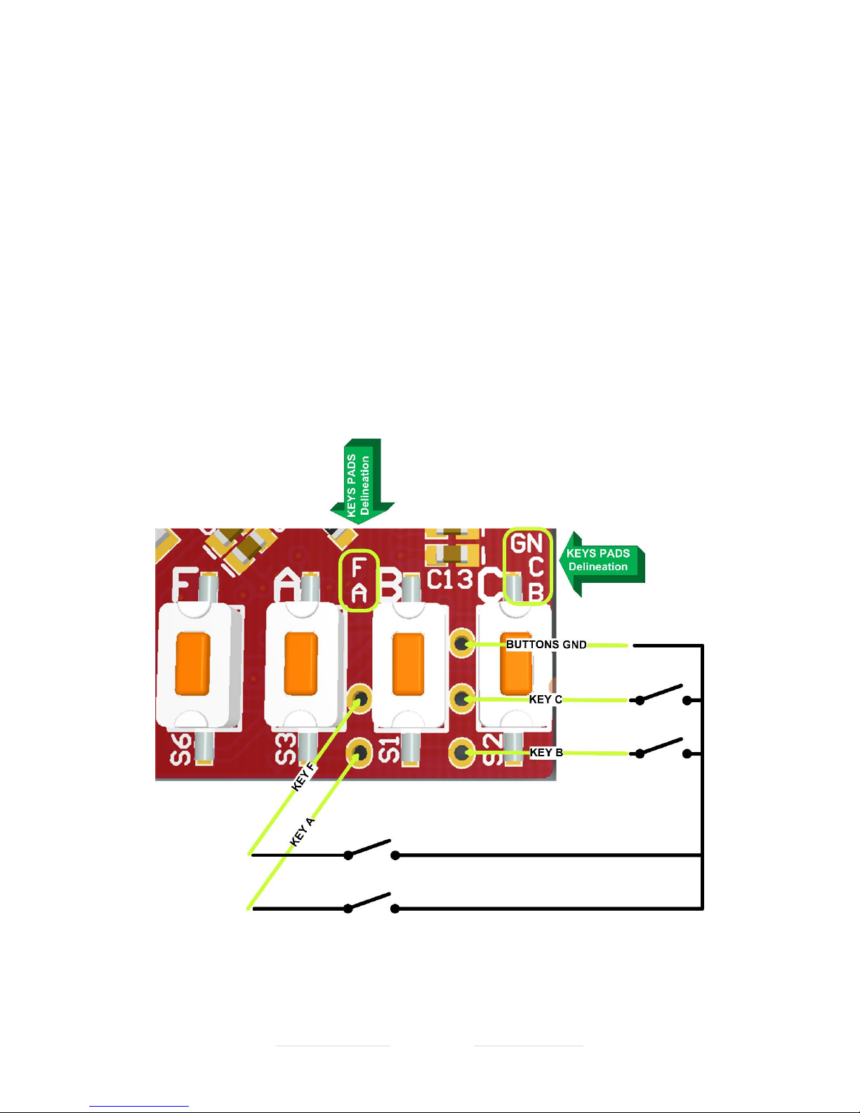
UPS PIco HV3.0A Firmware Code 040 Print Date 18.08.2017
Designed and Manufactured by PiModules and ModMyPi
www.pimodules.com www.modmypi.com
User Buttons (Keys)
User buttons A, B and C in the UPS Pico HV3.0 HAT are analog buttons, that means
when pressed change the level voltage that is read by integrated A/D converter, value
of it is interpreted by the firmware and the result is loaded to a proper system variable
and can be read by user. The F button is a digital interrupt driven button and his value
can not be read by the user
Each User Key and FSSD Key (buttons) has an additional THT pads that allows to be
used by user for their own mounted buttons outside of the UPS PIcoHV3.0 HAT or
case. Each of such user added buttons (keys) need just short to the system ground
when pressed.
Reading of User Buttons values can be done by accessing the system variable by any
software or by command line.
Figure 49 UPS PIco HV3.0A External Connectivity

UPS PIco HV3.0A Firmware Code 040 Print Date 18.08.2017
Designed and Manufactured by PiModules and ModMyPi
www.pimodules.com www.modmypi.com
To make working external keys (buttons), user need to solder cables to the THT key
pads. It is not recommended to use a very long cable (due to analog implementation
of the keyboard), their length should not be longer than 100 – 150 mm. However, we
never tested longer cable and if user need to use longer cables should test it on their
site. To make external keys workable user need to short each one with GN THT pad
when pressed. In example if user need to have external access to the FSSD (F) button,
need to install button that short the F pad with the GN pad when pressed. Similar
approach should be followed with other keys. Above picture show how external key
(buttons) need to be connected. It is not needed to connect all of them.
The key register holds the latest value of pressed key, so user need to write i.e. 0x00
after reading, to recognize that new key has been pressed (when pressed again, even
the same key). Current implementation requires timed (pooling) reading of this
register to recognize that a key has been pressed. In the future, it is planned to
implement interrupt driven handler for this and other functionalities.
Example of use
sudo i2cget -y 1 0x69 0x1A should return 1, 2 or 3
The pressed key value will remain in the register until new value will be written when
key (new one or the same) will be pressed. Therefore, user should write zero to this
register after reading to recognize and read again the new (or the same) key if (when)
pressed.
sudo i2cset -y 1 0x69 0x1A 0x00

UPS PIco HV3.0A Firmware Code 040 Print Date 18.08.2017
Designed and Manufactured by PiModules and ModMyPi
www.pimodules.com www.modmypi.com
UPS PIco HV3.0 HAT Sound Generation System
The UPS PIco HV3.0 HAT is equipped with Enhanced Sound Generation System. It is providing
a user interface on various states of UPS PIco HV3.0 HAT conditions, but it is also available for
dedicated user applications offering the whole range of acoustic frequencies full
programmable by user.
There are 2 registers that are responsible for the generating sound bfreq and bdur. To
generate sound user, need to program first the required frequency and then the required
duration is 10th of ms.
Current implementation need to program one be one sound when generated. The maximum
duration is 255 x 10 ms = 2.55 seconds
Additionally, it is possible to deactivate it permanently, by setting the bmode register to 0x00.
The default value is active
0x0D
bmode
Byte
Common
R/W
Integrated Sounder Mode
Read: Anytime, Return actual bmode value
Write: 0x00 – Unconditional Disable the Sounder
Write: 0x01 – Unconditional Enable the Sounder
Default Value: 0x01
0x0E
bfreq
Word
Common
R/W
Frequency of sound in Hz
0x10
bdur
Byte
Common
R/W
Duration of sound in 10th of ms (10 = 100 ms)
Example of use
sudo i2cset -y 1 0x6D 0x00 Deactivate permanently the buzzer (no sunds wil be played)
sudo i2cset -y 1 0x6D 0x01 Activate permanently the buzzer (default value)
In order to play sound buzzer need to be activated firstly.
sudo i2cset -y 1 0x6B 0x0e 1047 w Set the frequency to C (1047 Hz) note
sudo i2cset -y 1 0x6B 0x10 100 Set the duration to 1 second
After Sound execution, the bdur register is 0 again.

UPS PIco HV3.0A Firmware Code 040 Print Date 18.08.2017
Designed and Manufactured by PiModules and ModMyPi
www.pimodules.com www.modmypi.com

UPS PIco HV3.0A Firmware Code 040 Print Date 18.08.2017
Designed and Manufactured by PiModules and ModMyPi
www.pimodules.com www.modmypi.com
UPS PIco HV3.0 Bi Stable Relay
The UPS PIco HV3.0 HAT can be equipped with Bi Stable Relay with single coil. This
Relay is standard offered with version UPS PIco HV3.0 HAT Plus, it can be also ordered
separately and added to the UPS PIco HV3.0 HAT Stack/TopEnd. In both cases this
Relays is not mounted on the PCB and user need to do it by himself. The assembly
(soldering) of the Bi Stable Relay on the UPS PIco HV3.0 HAT PCB it is very easy task
and can be done by anybody using simple soldering iron. However it is also possible
that this assembling can be ordered to be done by us, if customer order directly on
the eshop or any other eshop that offer such service.
The main benefit of the Bi Stable Relay is the power consumption. The Bi Stable Relays
consume power only when switching from one state to another. All other times are
not consuming power at all. So, we called it Zero Power Relay. Driving of such relays
are little bit more complicated than the usual ones, however user not need to care
about that as electrical drivers are assembled on and offered with each UPS PIco HV3.0
HAT PCB. Each Bi-Stable Relay does not have states NO (Normal Open) or NC (Normal
Close), it has Reset and Set state instead. By switching of the Bi Stable Relay, user
changes the state from Reset to Set and vice versa. User should know that If Bi Stable
Relay change their status Reset/Set will stay on it (also when power will be completely
removed) until new switch commend will be send. If Bi Stable Relay receives one
command Reset or Set, sending multiple times of the same will not change anything.
To change status must be send opposite one i.e. if s Reset, the opposite one is Set.
Bi Stable Relay Contact description
Meaning
Normally Close Output (on Set State)
On Set State this contact is closed and have connection
with Common. Similar to the “normal” Relay NC (Normal
Close)
Common Output (on Reset/Set State)
On Reset/Set States this contact is switching between
NCO/NOO
Normally Open Output(on Set State)
On Set State this contact is Open and does not have
connection with Common. Similar to the “normal” Relay
NO (Normal Open)
Bi Stable Relay Basic Technical Specifications
Arrangement
2 form C (DPDT)

UPS PIco HV3.0A Firmware Code 040 Print Date 18.08.2017
Designed and Manufactured by PiModules and ModMyPi
www.pimodules.com www.modmypi.com
Contacts Material
Gold overlay silver alloy
Contacts Resistance (initial)
Maximum 50 mΩ (at 1 A 6 VDC)
Contacts Rating (resistive)
0.5 A 125 VAC or 1 A 30 VDC
Contacts Maximum Carrying Current
2 A
Contacts Maximum Switching Power
62.5 AV/30 W
Contacts Maximum Switching Voltage
250 VAC, 220 VDC
Contacts Operate (at nominal voltage)
Maximum 6 ms
Contacts Release (at nominal voltage)
Maximum 4 ms
Due to construction of UPS PIco HV3.0 PCB we do not recommend to use Integrated
Bi Stable Relay for switching of higher voltages/currents other than 32 VDC/1A per
switching contacts. The Integrated Bi Stable Relay contain a pair of independent
switching contacts that can be used separated for 2 different and independent
switching devices or connected in parallel if higher current (double) is needed.
Due to PCB construction It is absolutely not allowed to use the Integrated Bi Stable
Relay for switching 220 V AC at any current, even very low.

UPS PIco HV3.0A Firmware Code 040 Print Date 18.08.2017
Designed and Manufactured by PiModules and ModMyPi
www.pimodules.com www.modmypi.com
Example of use
sudo i2cset -y 1 0x6B 0x0c 0x00 should Reset the Bi Stable Relay
sudo i2cset -y 1 0x6B 0x0c 0x01 should Set the Bi Stable Relay
Each time when Bi Stable Relay is changing his state a characteristic “tick” is audible.
Multiple execution of the same command is not changing anything.
0x0C
brelay
Byte
Common
R/W
Zero Power Bi Stable Relay
Write: 0x01 Set
Write: 0x00 Reset

UPS PIco HV3.0A Firmware Code 040 Print Date 18.08.2017
Designed and Manufactured by PiModules and ModMyPi
www.pimodules.com www.modmypi.com
UPS Pico HV3.0 HAT IR Receiver Interface
TBC
UPS Pico HV3.0 HAT Programmable Auxiliary 5V@750 mA and
3.3V@150 mA Interface
The UPS PIco HV3.0 HAT is equipped with Auxiliary and 3.3V@150mA supply that are
independent from the 5V of the Raspberry Pi®. There are programmable and battery
backed up (if programmed by user), provide continuously supply even if Raspberry Pi®
is switched off. The Auxiliary 5V@750mA is over current protected with PPTC fuse on
the 5V@750mA as also reverse current draw with Schottky diode. Therefore, due to
small voltage drop the final voltage is about 4.85V, instead of the 5.0V. The
3.3V@150mA is only protected with LDO embedded over current protection. These
Auxiliary and 3.3V@150mA are addressed to supply devices that need to be running
even if Raspberry Pi® is switched off i.e. USB HUB, PIR Sensor, additional external high
current relay, Add on PCBs with extra hardware etc.
0x06
enable5V
Byte
Common
R/W
Defines usage of the Auxiliary 5V@750mA:
0x00 – Auxiliary 5V and 3.3V are not battery backed-up
0x01 – Auxiliary 5V and 3.3V are battery backed-up
Default Values is OFF
Other codes are not allowed
Example of use
sudo i2cset -y 1 0x6B 0x06 0x00 the Auxiliary 5V and 3.3V will be not battery backed-
up and stop working when power will be cut-off on the GPIO
sudo i2cset -y 1 0x6B 0x06 0x01 the Auxiliary 5V and 3.3V will be battery backed-up
and will continue supply also when 5V will be not available on the GPIO

UPS PIco HV3.0A Firmware Code 040 Print Date 18.08.2017
Designed and Manufactured by PiModules and ModMyPi
www.pimodules.com www.modmypi.com

UPS PIco HV3.0A Firmware Code 040 Print Date 18.08.2017
Designed and Manufactured by PiModules and ModMyPi
www.pimodules.com www.modmypi.com
UPS PIco HV3.0 Serial Port(s)
The UPS PIco HV3.0 is equipped with 2 serial ports. One of them is connected directly
to the Raspberry Pi ® Serial Port, and the second one is available for user applications.
Both Serial Ports are full programmable and the data rate can be set by user, as also
can be enabled or disabled. In addition, there is an internal routing option where one
port can receive and send data over the other one. This allows connecting the
Raspberry Pi® serial port to the external RS232 12V interface (via Terminals Blocks
PCB) or to 5V tolerant without any additional Jumpers or Cables. In addition the
second Serial port of the UPS PIco HV3.0 can be used as a second serial port routed
directly to the I2C interface (this option is not unlocked yet, and will be available within
one of the next firmware update). The UPS PIco HV3.0 by default is set OFF and
Raspberry Pi® Serial port can be used for any other applications. If it is needed it can
be set ON, as also the set the data rate. Setting the data rate sets it for both UPS PIco
HV3.0 serial ports.
After any firmware update the UPS PIco HV3.0 Serial Ports(s) must be set again. It is
done via PIco variable rs232_rate. The following settings are available:
Setting Value
Meaning
0x00
UPS PIco HV3.0 Serial Port is OFF
Default value
0x01
UPS PIco HV3.0 Serial Port is ON and
data rate is set to 4800 pbs
0x02
UPS PIco HV3.0 Serial Port is ON and
data rate is set to 9600 pbs
0x03
UPS PIco HV3.0 Serial Port is ON and
data rate is set to 19200 pbs
0x04
UPS PIco HV3.0 Serial Port is ON and
data rate is set to 38400 pbs
0x05
UPS PIco HV3.0 Serial Port is ON and
data rate is set to 57600 pbs
0x0F
UPS PIco HV3.0 Serial Port is ON and
data rate is set to 115200 pbs
Example of use
sudo i2cset -y 1 0x6b 0x02 0x00 Disable PIco RS232 and set tri state the TXD and RXD pins
sudo i2cset -y 1 0x6b 0x02 0x05 Enable the PIco RS232 and set the data rate to 57600 bps
sudo i2cset -y 1 0x6b 0x02 0x0F Enable the PIco RS232 and set the data rate to 115200 bps

UPS PIco HV3.0A Firmware Code 040 Print Date 18.08.2017
Designed and Manufactured by PiModules and ModMyPi
www.pimodules.com www.modmypi.com
UPS PIco HV3.0 FAN Control (Active Cooling System)
The UPS PIco HV3.0 can be equipped with Active Cooling System based on micro FAN
and dedicated temperature sensor. The PIco FAN is full PWM controlled rotation
speed from 0% up to 100%. It can be manually set ON or OFF on per-selected speed,
as also automatically based on preset temperature threshold. It can be done via the
following registers placed at the I2C address 0x6b (0x11, 0x12, 0x13).
0x11
fmode
Byte
Common
R/W
Integrated Fan Running Mode
Read: Anytime, Return actual fmode value
Write: 0x00 – Unconditional Disable the FAN with
selected speed from the fspeed
Write: 0x01 – Unconditional Enable the FAN FAN
with selected speed from the fspeed
Write: 0x02 – Automatic ON/OFF with defined
speed in the fspeed, ON when temperature read in
sensor T0-92 is higher than fttemp threshold, OFF
when lower.
Default value is set to 0x02 – Automatic ON/OFF
When written 0x02 to this register data are stored
in the internal EEPROM. So, even if UPS PIco
HV3.0 will be reset, automatic setup will be
recovered. All other data (0x00, or 0x01) are not
stored in the internal EEPROM.
When UPS PIco is going down to the LPR mode,
the FAN is automatically disabled, and enabled
again when the UPS PIco returns to normal work
0x12
fspeed
Byte
Common
R/W
Integrated Fan Speed
Read: Anytime, Return actual fspeed value
Write: 00 – Selected speed when OFF is 0% (not
running)
Write: 100 – Selected speed when ON is 100% (full
speed running)
Any other (0-100) number is allowed and means
% of speed and current consumption
Default speed is set to 50%
Any data written to this register are stored in the
internal EEPROM. So, even if UPS PIco HV3.0 will
be reset, will be recovered.
0x13
fstat
Byte
Mirror
Read
Read: Anytime, Return actual if FAN is actually
running or not (for remote users)
When FAN is set to be running (even if not
connected physically) the FAN LED is lighting. The
intensity of the FAN LED is depending of the FAN
Speed (PWM)

UPS PIco HV3.0A Firmware Code 040 Print Date 18.08.2017
Designed and Manufactured by PiModules and ModMyPi
www.pimodules.com www.modmypi.com
0x14
fttemp
Byte
Mirror
R/W
Integrated Fan Temperature Threshold in
Automatic Mode
BCD Fan Running threshold temperature in Celsius,
2 digits i.e. 35, means 35 Celsius.
In order to be used (automatic FAN ON/OFF) need
to set fmode to 0x02. Maximum temperature is 60
Celsius. Higher values will be ignored. FAN will
start at 36 Celsius and stop at 35 Celsius.
Read: Anytime, Return actual fspeed value
Write: 00 – 60 Sets the TO-92 temperature
Threshold for the Automatic FAN Start/STop
Default value is set to 35 Celsius
Example of use – Manual FAN ON/OFF
sudo i2cset -y 1 0x6b 0x13 100 Set the FAN speed to 100
sudo i2cset -y 1 0x6b 0x12 0x01 Set the FAN ON
sudo i2cset -y 1 0x6b 0x12 0x00 Set the FAN OFF
Example of use – Automatic FAN ON/OFF
sudo i2cset -y 1 0x6b 0x13 100 Set the FAN speed to 100
sudo i2cset -y 1 0x6b 0x12 0x02 Set the FAN ON as an Automatic
The default setup is Automatic Mode with 35 Celsius and 50% of FAN speed, so user
do not need to change anything if like just to use the FAN. If higher cooling
performance is needed (however with more noise) then the fspeed should be set to
100 (100%), similar with temperature threshold fttemp. However please kindly notice
that FAN speed and temperature threshold have been set in order to have best
performance with lowest noise.
UPS PIco HV3.0 Battery Type Selection
The UPS PIco HV3.0 is supporting 3 different chemistry battery types:
• the LiPO
• and the LiFePO4
• Li-Ion

UPS PIco HV3.0A Firmware Code 040 Print Date 18.08.2017
Designed and Manufactured by PiModules and ModMyPi
www.pimodules.com www.modmypi.com
Both chemistry batteries are available in 2 capacities. Therefore the UPS PIco HV3.0
can be supplied with the following batteries:
• The standard LiPO battery 450 mAh which comes with the UPS PIco HV3.0
• The enhanced LiPO battery with capacity 4000 mAh
• The enhanced LiPO battery with capacity 8000 mAh
• The enhanced LiFePO4 battery with capacity 4000 mAh
• The enhanced LiFePO4 battery with capacity 8000 mAh
Batteries with different chemistry offers different unique features, and needs to be
specified on the system setup when changed. The core differences between both
chemistry batteries are listed here below. The battery type setting declare the
chemistry and not the capacity of the battery. Declaration of the battery chemistry is
needed due to different threshold voltages and slightly different charging algorithm.
It is mandatory to have declared a proper battery chemistry for a proper system
functionality. The default battery chemistry is the LiPO and if not changed it is not
needed to change the declaration. Only if the user use the enhanced LiFePO4 batteries
it is need to proceed with changed of the battery chemistry declaration.
LiFePO4 Battery
Nominal voltage
3.2 V
Peak voltage
3.65 V
Absolute Minimum discharge voltage
2.0 V
CV charge voltage [100%]
3.65 V
CV charge voltage [95%]
3.5 V
Charge Temperature
0°-40°C
Discharge Temperature
-10°-60°C
0x6B -> UPS PIco Module Commands
0x07
battype
Byte
Common
R/W
Defines used battery chemistry type:
0x46 – LiFePO4 (ASCII : F) used in version Stack/TopEnd
0x51 – LiFePO4 (ASCII: Q) used in version Plus
0x53 – LiPO (ASCII: S) used in version Stack/TopEnd
0x50 – LiPO (ASCII: P) used in version Plus
Other codes are not allowed

UPS PIco HV3.0A Firmware Code 040 Print Date 18.08.2017
Designed and Manufactured by PiModules and ModMyPi
www.pimodules.com www.modmypi.com
Example of use
sudo i2cset -y 1 0x6b 0x07 0x46 LiFePO4 (ASCII : F) used in version Stack/TopEnd
sudo i2cset -y 1 0x6b 0x07 0x51 LiFePO4 (ASCII: Q) used in version Plus
sudo i2cset -y 1 0x6b 0x07 0x53 LiPO (ASCII: S) used in version Stack/TopEnd
sudo i2cset -y 1 0x6b 0x07 0x50 LiPO (ASCII: P) used in version Plus
Caution: The UPS PIco HV3.0 HAT PCB has declared always the default battery
chemistry type, and when firmware update is executed the battery chemistry is always
changed to PCB defaults, therefore it is needed to re-declare the battery type after
firmware update to the used one by the system. Some industrial customers have
default declared the LiFePO4 in their systems, but usual the default battery chemistry
is LiPO.
UPS PIco HV3.0 HAT Measuring and Monitoring System
The UPS PIco HV3.0 offer to the user an extended Measuring and Monitoring System
that measure and report many system parameters trough installed sensors. Each
sensor is reporting the UPS PIco HV3.0 HAT status via dedicated variables. In addition
there is access to the integrated 12 bits 3 x A/D converters. All monitoring system data
are collected in a single entity called PIco Status and exists at the I2C address 0x69.
Detailed specifications for each variable (register) as also examples are provided in
next pages. The sensors are:
• Powering Mode
• System Variable Changed
• System Error
• Battery Powered Available Running Time (calculated on battery capacity and
system current consumption)
• Battery Level
• Raspberry Pi® GPIO 5V Level
• External Powering Level
• Incoming (from Raspberry Pi® GPIO 5V) current

UPS PIco HV3.0A Firmware Code 040 Print Date 18.08.2017
Designed and Manufactured by PiModules and ModMyPi
www.pimodules.com www.modmypi.com
• Outgoing (to Raspberry Pi® GPIO 5V) current
• Incoming (from External Powering) current
• A/D converter 0 Level
• A/D converter 1 Level
• A/D converter 2 Level
• Key pressed (described in the User Applications Hardware Interfaces)
• Embedded NTC temperature (measured on PIco PCB)
• TO-92 Sensor Temperature (measured near to the Raspberry Pi® PCB )
• Opto Coupler
• Integrated Charger Status
• Running PIco validation
• PCB versions
• Bootloader Versions
• Firmware Version
Green marked features has been not activated yet.
Powering Mode

UPS PIco HV3.0A Firmware Code 040 Print Date 18.08.2017
Designed and Manufactured by PiModules and ModMyPi
www.pimodules.com www.modmypi.com
Battery Level
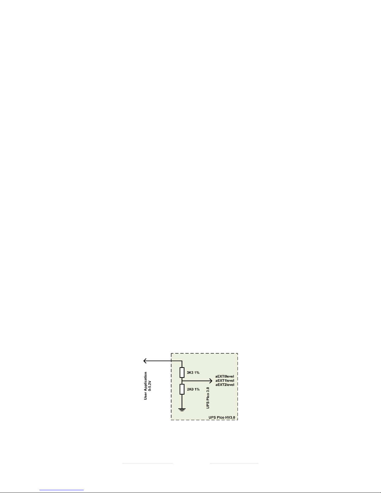
UPS PIco HV3.0A Firmware Code 040 Print Date 18.08.2017
Designed and Manufactured by PiModules and ModMyPi
www.pimodules.com www.modmypi.com
Raspberry Pi® GPIO 5V Level
External Powering Level
UPS PIco HV3.0 12-bit A/D converters
The UPS PIco HV3.0 is equipped with 3 x 12 bits A/D converters. Access to their
conversion data is possible via dedicated registers placed at the I2C address 0x69
(0x14, 0x16, 0x18). Those A/D converters read continuously data every 250 uS with
conversion time of 3.5 uS per sample. However due to implemented low noise
software enhanced filtering in the firmware the effective rate data rate is around of
0.001 sec per reading (each A/D register values is refreshed every 1000us).
Each of the A/D converters is pre-scaled to measure voltage 0-5.2V with implemented
on the UPS PIco HV3.0 HAT resistor divider. They are named aEXT0, aEXT1, aEXT2.
However, there is also a possibility for the user (if use Terminal Block PCB or additional
external resistor) to use two of them as pre scaled of 0-10V, 0-20V, or 0-30V. These
two A/D converters are named aEXT1 and aEXT2.
Due to electrical requirements of the integrated A/D converters the impedance is set
to low values, therefore some high impedance sensors cannot be read properly as
could require higher impedance of A/D converter interface. On such cases it is
recommended to use Voltage Follower that converts the sensor high impedance to
UPS PIco HV3.0 HAT A/D converters lower one.
This functionality (of the Voltage Follower) has been implemented on the Terminal
Blocks PCB, where on one of the A/D’s converters (the aEXT0) a Voltage Follower has
been assigned and allows to convert high impedance of any possible used sensor to
low impedance on the A/D side. A detailed description of the Terminal Blocks PCB and
their functionalities are described in separate section of this manual.
The basic circuit of all A/D converters (the resistor dividers) are shown here below, it
is same to all implemented A/D converters in the UPS PIco HV3.0 HAT.

UPS PIco HV3.0A Firmware Code 040 Print Date 18.08.2017
Designed and Manufactured by PiModules and ModMyPi
www.pimodules.com www.modmypi.com
If user decide to use Higher Voltage Interface as pre-scaled of 0-10V, 0-20V, or 0-30V
the Terminal Blocks PCB should be used, or an additional resistor need to be added
externally, like in the below pictures. In addition, the register setA_D (0x08) at address
0x6b should be set to a proper value according the below table to keep the proper
voltage conversion. If user not like to use embedded voltage converter, then it is
needed to disable it via a proper command and read the raw data directly from the
related register. All A/D readings have internal reference of 2.048V and are filtered by
the firmware with “Olympic Score” and “Low Pass” Filtering.
Caution: The UPS PIco HV3.0 has implemented an ESD protection on each A/D
converter input. This protection protects the system from ESD discharges and does
not from continuously high voltage applied.
Therefore, it is very important if High Voltage used (10V, 20V or 30V), to be sure that
a proper resistor(s) has been used. If smaller resistor(s) that required will be used,
then the A/D input will be destroyed permanently, and very possible also the whole
UPS PIco HV3.0 HAT PCB
Therefore, user need to take care to be sure that a proper values of resistor(s) has
been used.

UPS PIco HV3.0A Firmware Code 040 Print Date 18.08.2017
Designed and Manufactured by PiModules and ModMyPi
www.pimodules.com www.modmypi.com
setA_D
Values
AEXT0level
Scale
AEXT1level
Scale
AEXT2level
Scale
AEXT1
Resistor
AEXT2
Resistor
0x00
5.2V
5.2V
5.2V
0K
0K
0x01
5.2V
5.2V
10V
0K
3K3
0x02
5.2V
5.2V
20V
0K
12K0
0x03
5.2V
5.2V
30V
0K
24K0
setA_D
Values
AEXT0level
Scale
AEXT1level
Scale
AEXT2level
Scale
AEXT1
Resistor
AEXT2
Resistor
0x00
5.2V
5.2V
5.2V
0K
0K
0x10
5.2V
10V
5.2V
3K3
0K
0x20
5.2V
20V
5.2V
12K0
0K
0x30
5.2V
30V
5.2V
24K0
0K
* Red marked table settings are not unlocked yet in current firmware version
Any combination of data provided on above table is allowed. The register setA_D is 8
bit. The 4th MSB bits are responsible for the AEXT1level pre-scale, and the 4th LSB bits
are responsible for the AEXT2level pre-scale.
On the UPS PIco HV3.0 PCB the AEXT0level is marked as A50, the AEXT1level is
marked as A15 and the AEXT2level is marked as A30.
If user need read raw data, then there is a need to write 0xFF to the setA_D register.
With raw data option the basic standard resistor divider is used, and the input voltage
can not exceed the 5.2V. The maximum reading is 4095 (12 bit A/D). All A/D readings
have internal reference of 2.048V and are filtered by the firmware with “Olympic
Score” and “Low Pass” Filtering.

UPS PIco HV3.0A Firmware Code 040 Print Date 18.08.2017
Designed and Manufactured by PiModules and ModMyPi
www.pimodules.com www.modmypi.com
Example of use
sudo i2cget -y 1 0x69 0x14 w should return value of the aEXT0level
sudo i2cget -y 1 0x69 0x16 w should return value of the aEXT1level
sudo i2cget -y 1 0x69 0x18 w should return value of the aEXT2level
sudo i2cset -y 1 0x6b 0x08 0x00 sets all A/D readings to pre sacled 0-5.2V (default)
sudo i2cset -y 1 0x6b 0x08 0xff sets all A/D readings to raw data (0x0000-0x0fff)
Registers Located at 0x69 I2C address related to A/D readings
0x14
aEXT0level
Word
Mirror
Read
Means value of the first A/D converter pre scaled to
5.2V. Higher voltage could not be supplied. Readings
are in 10th of mV in BCD format
0x16
aEXT1level
Word
Mirror
Read
Means value of the second A/D converter pre scaled to
5.2V. Higher voltage could be supplied with an external
resistor divider. Readings are in 10th of mV in BCD
format. If added an extra resistor can be used as pre
scaled to 10, 20 or 30V.
0x18
aEXT2level
Word
Mirror
Read
Means value of the second A/D converter pre scaled to
5.2V. Higher voltage could be supplied with an external
resistor divider. Readings are in 10th of mV in BCD
format. If added an extra resistor can be used as pre
scaled to 10, 20 or 30V.
Registers Located at 0x6B I2C address related to A/D settings
0x08
setA_D
Byte
Common
R/W
Defines the pre scaler of the AEXT1level and the
AEXT2level registers.
The 4th MSB bits are responsible for the AEXT1level
pre-scale, and the 4th LSB bits are responsible for the
AEXT2level pre-scale.
Read: Anytime, Return actual setA_D value
Write: 0x00 – 5.2V prescale for the AEXT2level
Write: 0x01 – 10V prescale for the AEXT2level
Write: 0x02 – 20V prescale for the AEXT2level
Write: 0x03 – 30V prescale for the AEXT2level
Write: 0x00 – 5.2V prescale for the AEXT1level
Write: 0x10 – 10V prescale for the AEXT1level
Write: 0x20 – 20V prescale for the AEXT1level
Write: 0x30 – 30V prescale for the AEXT1level
Write: 0xFF – all A/D registers will contain raw data
RED Marked – not implemented yet

UPS PIco HV3.0A Firmware Code 040 Print Date 18.08.2017
Designed and Manufactured by PiModules and ModMyPi
www.pimodules.com www.modmypi.com
Embedded NTC temperature
TO-92 Sensor Temperature
Integrated Charger Status
• PCB versions
• Bootloader Versions
• Firmware Version

UPS PIco HV3.0A Firmware Code 040 Print Date 18.08.2017
Designed and Manufactured by PiModules and ModMyPi
www.pimodules.com www.modmypi.com
UPS PIco HV3.0 System Time Schedulers
The UPS PIco HV3.0 has implemented 2 independent, Time Schedulers. There are:
• The Basic Time Scheduler (BS)
• and, The Event Triggered RTC Based System Actions Scheduler (ETR SAS)
Both schedulers cannot be used at the same time, and if one of them is selected, the second
is deselected and vice versa.
The Register responsible for the Scheduler selection is located in the 0x6b Registers Set
0x6B -> UPS PIco 0x19 Time Scheduler Selector
This register is used to select the System Time Scheduler. Two values are possible 0x00
(default value) – which means Basic Scheduler, or 0x01 – which means Event Triggered RTC
Based System Actions Scheduler. Setting of it is necessary to select the proper System Time
Scheduler.
sudo i2cset -y 1 0x6b 0x19 0x00 to select BS (default values)
or
sudo i2cset -y 1 0x6b 0x19 0x01 to select ETR SAS

UPS PIco HV3.0A Firmware Code 040 Print Date 18.08.2017
Designed and Manufactured by PiModules and ModMyPi
www.pimodules.com www.modmypi.com
Basic Scheduler
This scheduler is basically used when UPS PIco HV3.0 hardware RTC is not used (therefore not
possible to set exact date, time; and synchronize with it) or when user need something ultrasimple, just to make ON/OFF the Raspberry Pi (so no needed to use the complex settings of
the ETR SAS). There are only few registered involved in this scheduler and setting up of them
is rapid. User need just to set how long Raspberry Pi® should be running, after what time it
will be repeated (if so) and how many times it must happen. The time resolution of the BS is
based on 1 minute, however everything is adjusted with 1 second accuracy, as each action
start/stop is executed at the beginning (first second) of internal RTC counted minute (even if
the internal RTC is not set, it is always running). Below picture explain the logic behind of this
Basic Scheduler.
Figure 50 Basic Scheduler
BS Definitions
There are some definitions that need to be specified to have better understanding of the BS
functionality. There are basically similar to the ETR SAS definitions (described in the next
chapter), however are simplified due to adaptation to this simple Basic Scheduler. There are:
BS Action –It is ON/OFF the Raspberry Pi® only
BS Duration Time – Specify time between BS Action (ON of the Raspberry Pi®) and their
opposite state (OFF of the Raspberry Pi®). In example if Raspberry Pi® Power ON, the opposite
state is Raspberry Pi® Power OFF. Therefore, BS Duration Time is time between ON and OFF
the Raspberry Pi®.
BS Repetition Time – The BS Repetition Time defines the time between beginnings of first
and the repeated BS Action.
BS Multiplier – Defines how many times BS Action will be repeated, up to 254 times or
infinitely

UPS PIco HV3.0A Firmware Code 040 Print Date 18.08.2017
Designed and Manufactured by PiModules and ModMyPi
www.pimodules.com www.modmypi.com
Basic Scheduler Involved PICo Registers/Sets
The following PICo Registers are involved in the Basic Scheduler programming. There are:
• BS_duration_time
• BS_repetition_time
• BS_multipier
In addition, user need to set properly the Time Scheduler Selector and make running the BS
by using BS_ RUN Register. The Basic Scheduler will start at once (start their timers) after the
BS_RUN will be set to ON (0x01).
All Registries related to the Basic Scheduler are located at the 0x6B -> UPS PIco Module
Commands. There are:
0x6B -> UPS PIco 0x1A BS_duration_time (in minutes)
This register defines how long the ON of Raspberry Pi® (called Action) will be running after
starting up. This time must be shorter by at least 1 minute than the repetition time. In
Example, if the Raspberry Pi® the repetition time is 11 minutes, the duration time must be
maximum 10 minutes (to give 1-minute time for system shutdown). The default value is 0x01.
Each value is in minutes. The maximum time is 0xfe (254 minutes). This register can be read
when Raspberry Pi® is running, user will see the decreased value as time is passed.
0x6B -> UPS PIco 0x1B BS_repetition_time (in minutes)
This register defines how long after start of the Raspberry Pi® (Action) will be repeated (if so).
This time must be longer by at least 1 minute than the duration time of the ON Raspberry Pi®
(Action). In Example, if the Raspberry PI will be running for 10 minutes (duration time = 10),
the repetition time must be minimum 11 minutes (to give 1-minute time for system
shutdown). The default value is 0x02. Each value is in minutes. This register can be read when
Raspberry Pi® is running, user will see the decreased value as time is passed.
0x6B -> UPS PIco 0x1C BS_multiplier
This register defines how many times the Basic Scheduler Action (Raspberry Pi® ON/OFF) will
be running. It can make it run counted times (from 1 up to 254). If programmed 0xff (255)
then the Action will be executed unlimited times (repeated continuously). This register can be
read when Raspberry Pi® is running, user will see the decreased value as counter is passed.
0x6B -> UPS PIco 0x1D BS_RUN
This register is used to make Basic Scheduler running (if all parameters are properly set). By
setting the BS_RUN = 0x01 the BS will start running. It is not possible to change any related to
BS register value when BS_RUN is active. To do so, you need to deactivate the BS_RUN first.
 Loading...