

Page 1
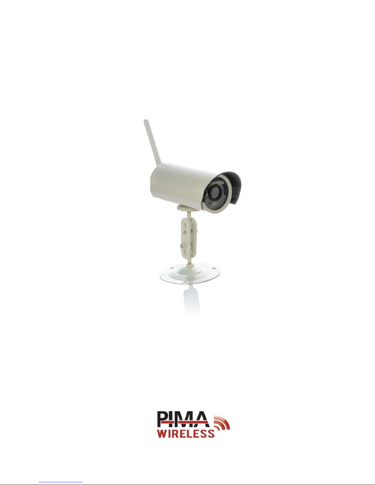
OutView
Outdoor Wireless Camera
Installation Guide
Page 2

OutView Installation Guide
2
Product Overview
The OutView is a Wireless Outdoor Still Image Camera. Integrated with the AlarmView Intruder
Alarm System, it is the Ultimate Solution for receiving High Quality Images for enhanced Security
and Outdoor Surveillance.
With its Slick White Design, the OutView can be used for Visual Perimeter Protection and a variety
of other applications.
Features
High Quality, Still Image Camera
Operated by Momentary Trigger from N.C. (Normally Close) Devices: Detectors, Relays, etc
Up to 7 m Flash, for Low-Light Conditions
Weather Resistant
Sun Light Protection
External AC adapter
IP65 Environment Protection
Out of the box
The OutView camera with a connected 4-wire cable
Terminal block
AC to DC adapter
Mounting bracket with Swiveling Arm
Allan wrench
3 screws + 3 wall plugs
To preserve its sealing and to avoid opening its enclosure, the OutView is
supplied with a cable connected to its internal terminal block.
Any attempt to open the enclosure will void the camera’s warranty.
Page 3
Quick reference guide
3
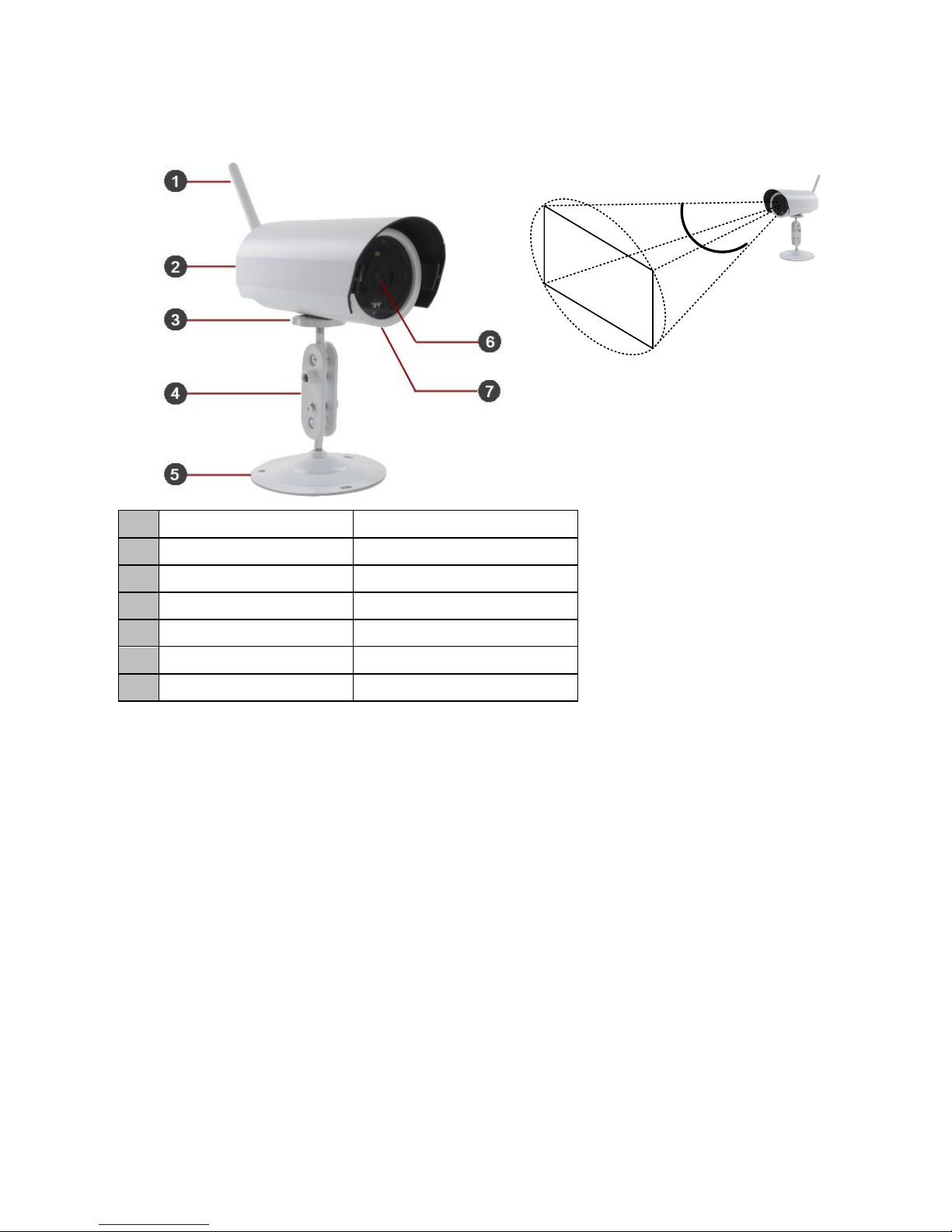
Quick reference guide
1
Antenna
2.4 GHz, 2-way Radio Link
2
Hood
Aluminum
3
Plastic Screw Fastener
For Camera Stability
4
Swiveling Arm
For Pan & Tilt Adjustment
5
Mounting Bracket
Wall/Surface Mounting
6
Lens
67° Field of View
7
Len’s Cap
Protective Shield
Installation
Placement guidelines
Keep the AC adapter as close as possible to the camera, to ensure optimal voltage and not to
affect the image quality and the flash
The AC adapter should be connected to an indoor AC outlet
The distance between the camera and the trigger source (detector) cannot exceed 50 m
Ensure that outdoor power cables, such as extension cords, are designed for outdoor use
Mount the camera on a solid flat surface only
Do not place the camera where rain and snow will hit the lens directly
Do not point the camera towards a light source
Do not have the camera in a shaded area looking out into a well-lit area, as this will display
poor results
How to mount the OutView
Before you mount the OutView camera, make sure it optimally covers the secured area.
Diagonal Field of View: 67
0
Page 4
OutView Installation Guide
4
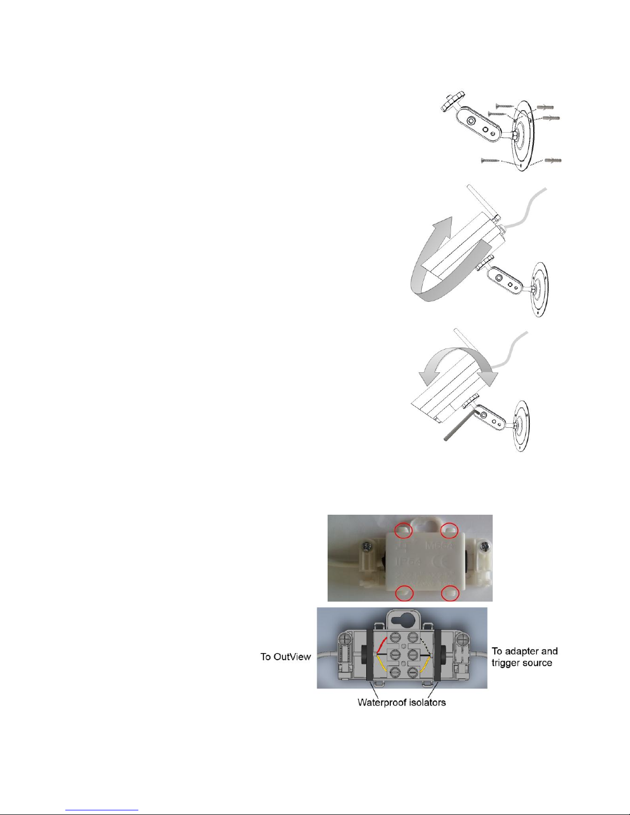
Follow the next steps to mount the camera:
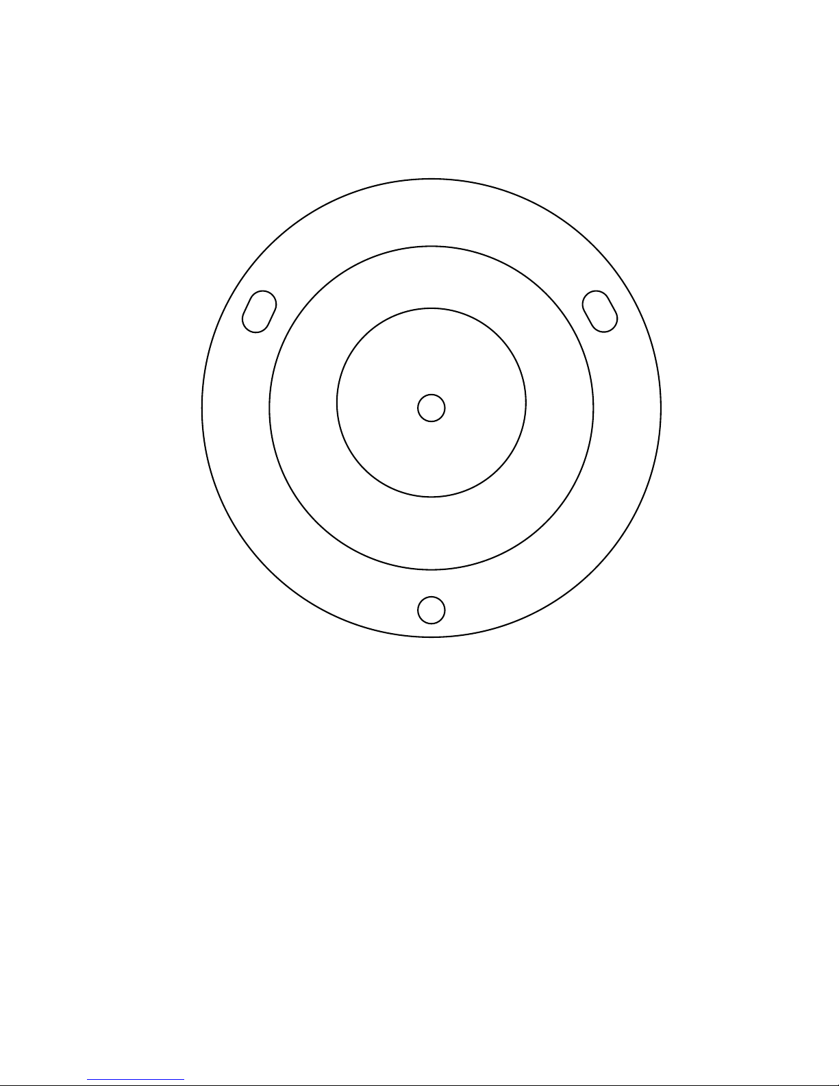
1. Use the template on page 11 and drill 3 matching holes
on the mounting surface.
2. Insert the supplied wall plugs and mount the bracket,
using the supplied screws.
3. Rotate the swiveling bracket’s plastic knob clockwise, to its
lower position.
4. Connect the camera to the bracket, by rotating it
clockwise.
5. Tighten the plastic knob to secure the camera.
6. Connect the camera’s cable to the terminal block and to
power; see the next section for details.
7. Adjust the field of view of the camera.
8. Tighten the bracket’s tilt screws with the supplied Allen
wrench.
How to connect the OutView
The OutView is supplied connected with a 3-wire cable to a junction box. The box has a terminal
block inside it. To connect the OutView, do the following:
1. Open the junction box:
push the clasps (encircled
in red in the image on the
right) outside and remove
the lid.
2. Pull out the black
waterproof isolator, on the
side without the wires.
3. Puncture a hole in the center of the isolator, for the wires of the AC adapter and the
trigger source.
4. Put the required wires through the isolator.
Page 5
Maintenance
5
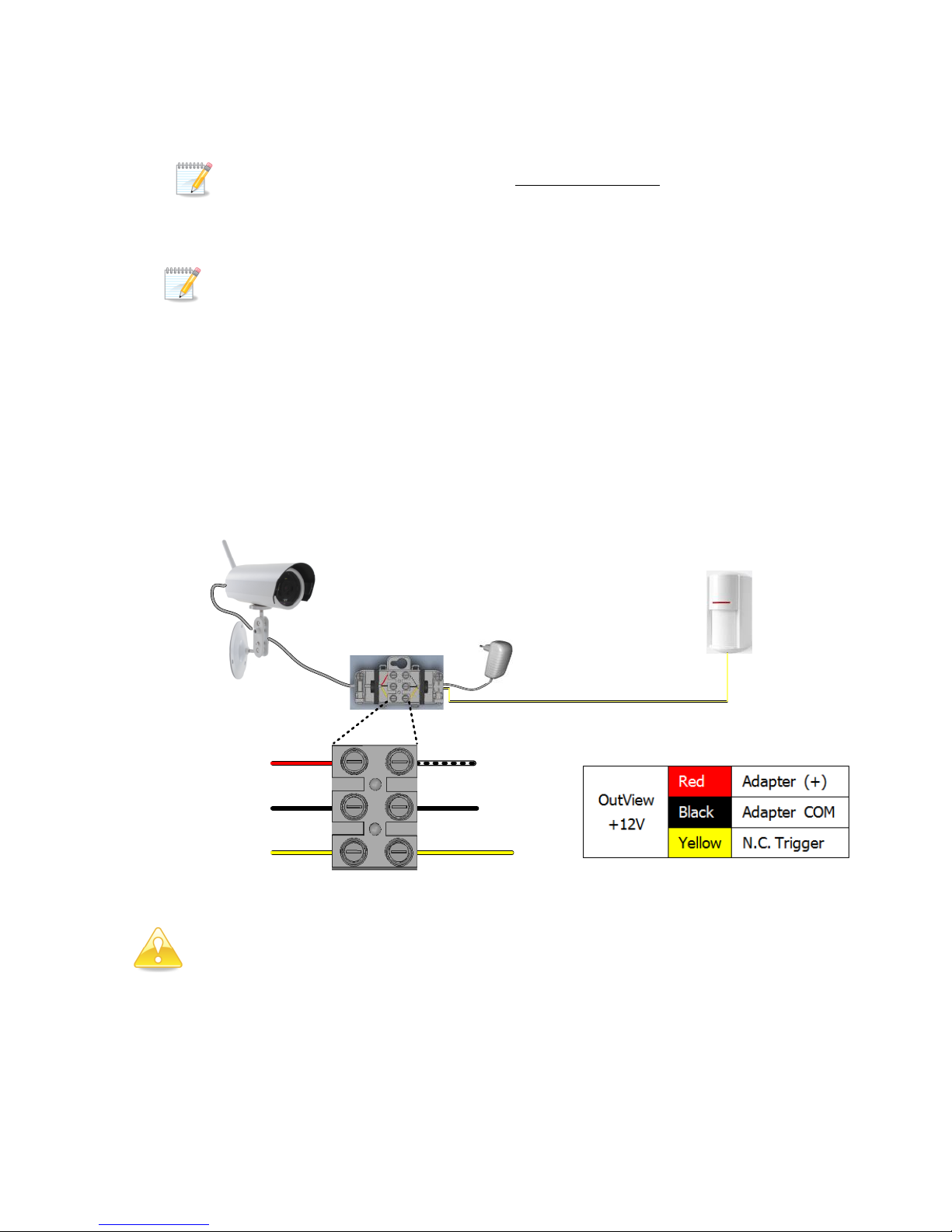
5. Connect the AC adapter wires to the Red (+) and Black (-) wires, on the terminal block. See
the next section for a diagram.
The positive wire of the AC adapter is marked with stripes
6. Connect the wire from the trigger source to the Yellow wire of the OutView, on the terminal
block. See the next diagram.
Two-state triggers, like door contacts and beam detectors, cannot be used.
7. Release the screw on the junction box, on the side of the adapter and the trigger wires, and
remove the plastic clip.
8. Put the isolator, now with the wires inserted into it, back in its place.
9. Replace the clip on the wires and fasten the screw.
10. Close the lid and make sure it is fastened by all four clasps.
11. Place the junction box in a weatherproof placement.
12. Plug the AC adapter to an indoor outlet.
Connection diagram
If the AC-DC adapter is also used to power the triggering detector,
make sure it does not exceed its power output.
The OutView does not report a restore event.
Maintenance
If the protective camera lens becomes dirty, clean it only with a lint-free cloth.
Trigger source (N.C.)
OutView
AC-DC
Adapter
Junction box
Red
Black
Yellow
AC-DC Adapter
Trigger source
(up to 50 m long)
OutView
(+)
(-)
Page 6

OutView Installation Guide
6
Technical specifications
Optical
Diagonal Field of View
67°
Camera type
VGA CMOS Color Camera
Visual type
JPEG, 320 x 240, up to 15 Kb per image
General
Adjustment
Mounting bracket with swiveling arm for Pan & Tilt adjustments
Trigger
Wired, Normally Close
Electrical
Adapter
12 VDC 2A AC-DC adapter, external
Current Consumption
Standby: 40 mA
Transmission: 160 mA
Flash pick current: 1500 mA
Flash
Type
Visible light strobe
Range
Up to 7 m
RF
Frequency
2.4 GHz ISM band
Modulation
Frequency Hopping Spread Spectrum (FHSS)
Supervision
2-way Radio Link, 20 sec interval
Event Transmission
Alarm, Image, Low Battery, Supervision
Range
Up to 100 m in open space 1
Secured Wireless
Network
Unique ID serial number: 48 bit + link key
Data encryption (up to 48-bit)
Physical
Dimensions
125 X 65 mm
Weight
With bracket: 443 g
Without bracket: 330 g
Hood
Aluminum
Environmental
Operating environment:
Outdoor, IP65 Environment Protection
Operating temperature:
-20 to +60 ºC
Humidity:
0 to 85%, non-condensing
RFI Protection:
10 V/m, up to 1000 MHz
1
Range might be impacted by building materials and interferences
Page 7

Limited Warranty
PIMA Electronic Systems Ltd. ("the Manufacturer") warrants its products hereinafter referred to as "the
Product" or "Products" to be in conformance with its own plans and specifications and to be free of defects
in materials and workmanships under normal use and service for a period of twelve (12) months from the
date of shipment by the Manufacturer. The Manufacturer's obligations shall be limited within the warranty
period and its option, to repair or replace the product or any part thereof. The Manufacturer shall not be
responsible for dismantling and/or reinstallation charges. To exercise the warranty, the product must be
returned to the Manufacturer freight prepared and insured.
The warranty does not apply in the following cases: improper installation, misuse, failure to follow
installation and operating instructions, alteration, abuse, accident or tampering, and repair by anyone other
than the Manufacturer.
The warranty is exclusive and expressly in lieu of all other warranties, obligations or liabilities, whether
written, oral, express or implied, including any warranty of merchantability or fitness for a particular
purpose, or otherwise. In no case shall the Manufacturer be liable to anyone for any consequential or
incidental damages for breach of this warranty or any other warranties whatsoever, as aforesaid.
This warranty shall not be modified, varied or extended, and the Manufacturer does not authorize any person
to act on its behalf in the modification, variation or extension of this warranty. This warranty shall apply to
the Product only. All products, accessories or attachments of others used in conjunction with the Product,
including batteries, shall be covered solely by their own warranty, if any. The Manufacturer shall not be
liable for any damage or loss whatsoever, whether directly, indirectly, incidentally, consequentially or
otherwise, caused by the malfunction of the Product due to products, accessories, or attachments of others,
including batteries, used in conjunction with the Products. The Manufacturer does not represent that its
Product may not be compromised and/or circumvented, or that the Product will prevent any death, personal
and/or bodily injury and/or damage to property resulting from burglary, robbery, fire or otherwise, or that
the Product will in all cases provide adequate warning or protection. User understands that a properly
installed and maintained alarm may only reduce the risk of events such as burglary, robbery, and fire
without warning, but it is not insurance of a guarantee that such will not occur or there will be no death,
personal damage and/or damage to property as a result.
The Manufacturer shall have no liability for any death, personal and/or bodily injury and/or damage to
property or other loss whether direct, indirect, incidental, consequential or otherwise, based on a claim that
the Product failed to function. However, if the Manufacturer is held liable, whether directly or indirectly, for
any loss or damage arising under this limited warranty or otherwise, regardless of cause of origin, the
Manufacturer's maximum liability shall not in any case exceed the purchase price of the Product, which shall
be fixed as liquidated damages and not as penalty, and shall be the complete and exclusive remedy against
the Manufacturer.
Warning: The user should follow the installation and operation instructions and among other things test the
product and the whole system at least once a week. For various reasons, including, but not limited to,
changes in environmental conditions, electric or electronic disruptions and tampering, the Product may not
perform as expected. The user is advised to take all necessary precautions for his/her safety and the
protection of his/her property.
Page 8

8
RoHS compliance
All our products are lead-free
ISO 9001 Certification
PIMA Electronic Systems is ISO 9001 certified
CE Declaration
Hereby,
Company: PIMA Electronic Systems Ltd.
Address: 5 Hatzoref Street, Holon 5885633
Country: Israel
Telephone number: +972.3.6506414
Fax number: +972.3.5500442
PIMA Electronic Systems Ltd. declares that the AlarmView system is in compliance with the essential
requirements and other relevant provisions of Directive 1999/5/EC.
Federal Communications Commission (FCC) Part 15 Statement
This equipment has been tested to FCC requirements and has been found acceptable for use. The FCC
requires the following statement for your information.
This equipment generates and uses radio frequency energy and if not installed and used properly, that is, in
strict accordance with the manufacturer’s instructions, may cause interference to radio and television
reception. It has been type tested and found to comply with the limits for a Class B computing device in
accordance with the specifications in Part 15 of FCC Rules, which are designed to provide reasonable
protection against such interference in a residential installation. However, there is no guarantee that
interference will not occur in a particular installation. If this equipment does cause interference to radio or
television reception, which can be determined by turning the equipment off and on, the user is encouraged to
try to correct the interference by one of the following measures:
If using an indoor antenna, have a quality outdoor antenna installed.
Reorient the receiving antenna until interference is reduced or eliminated.
Move the receiver away from the control/communicator.
Plug the control/communicator into a different outlet so that it and the receiver are on different
branch circuits.
If necessary, the user should consult the dealer or an experienced radio/television technician for
additional suggestions.
Page 9

9
The user or installer may find the following booklet prepared by the Federal Communications Commission
helpful: “Interference Handbook.” This booklet is available from the U.S. Government Printing Office,
Washington, DC 20402.
The user shall not make any changes or modifications to the equipment unless authorized by the Installation
Instructions or User’s Guide. Unauthorized changes or modifications could void the user’s authority to
operate the equipment.
All data contained herein is subject to change without prior notice.
Copyright © 2014 by PIMA Electronic Systems Ltd. All rights reserved. E&OE
This guide and the information contained herein are proprietary to PIMA Electronic Systems Ltd. Only
PIMA Electronic Systems Ltd. or its customers have the right to use the information.
No part of this guide may be re-produced or transmitted in any form or by any means, electronic or
mechanical, for any purpose, without the express written permission of PIMA Electronic Systems Ltd.
PIMA Electronic Systems Ltd. owns patents and patent applications, trademarks, copyrights, or other
intellectual property rights covering the subject matter in this guide.
The furnishing of this guide to any party does not give that party or any third party any license to these
patents, trademarks, copyrights or other intellectual property rights, except as expressly provided in any
written agreement of PIMA Electronic Systems Ltd.
Page 10

10
Page 11
11
Page 12
12
Pima Electronic Systems Ltd
5 Hatzoref Street, Holon 5885633, ISRAEL
Tel: +972.3.650.6414 Fax: +972.3.550.0442
www.pima-alarms.com
Distributed and Supported by:
P.N. 4410383
*4410383*
Ver: XX en, A1, Apr. 2014
 Loading...