

Page 1
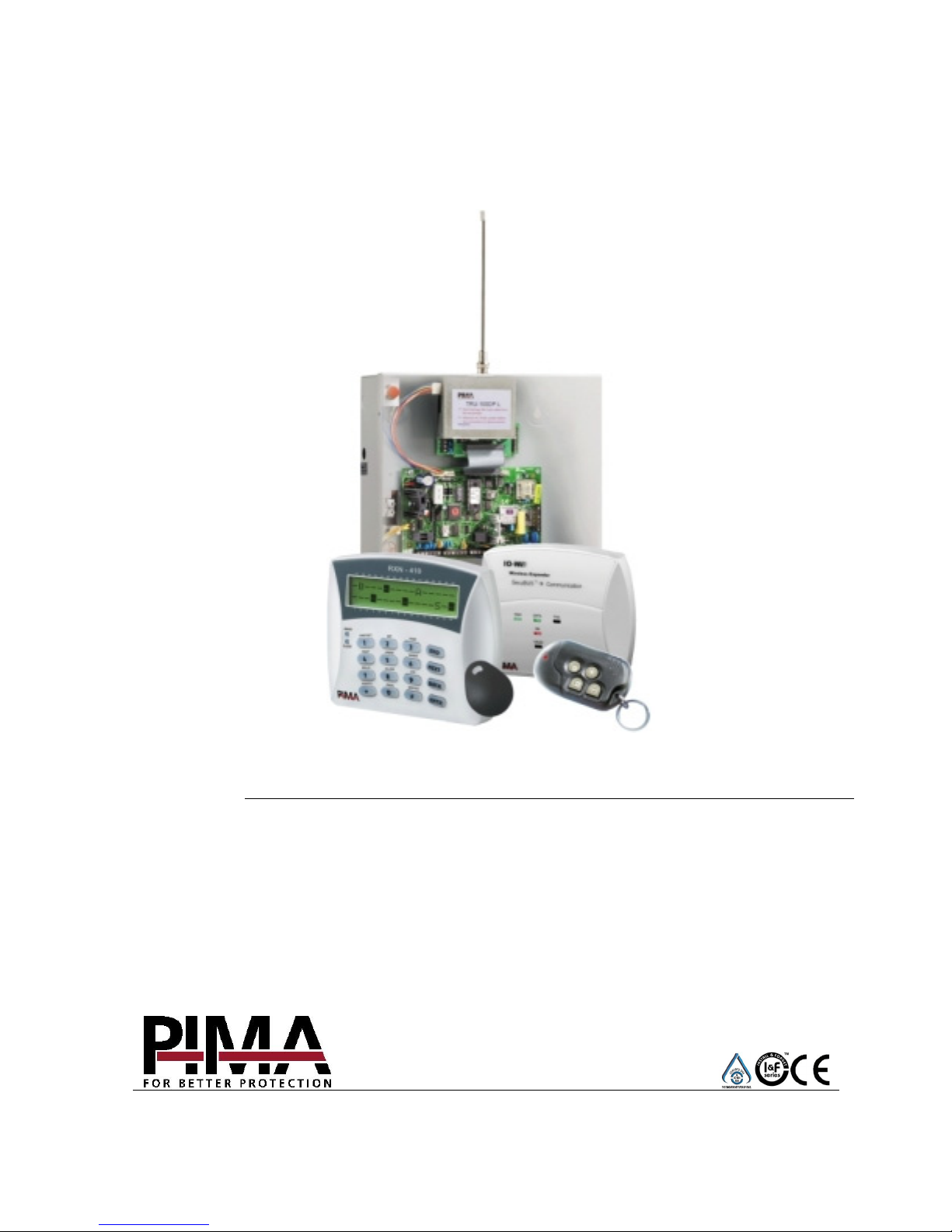
HUNTER-PRO SERIES
INTRUDER ALARM SYSTEMS FOR 8-144 ZONES
HUNTER-PRO 832, 896, 8144
INSTALLATION GUIDE
VERSION 6.0
PIMA Electronic Systems Ltd.
www.pima-alarms.com
P/N: 4410281, A1, XX en
March 2009
Page 2

2 HUNTER-PRO Series Installation Guide
PIMA Electronic Systems Ltd. does not represent that its Product may not be compromised
and/or circumvented, or that the Product will prevent any death, personal and/or bodily injury
and/or damage to property resulting from burglary, robbery, fire or otherwise, or that the
Product will in all cases provide adequate warning or protection. The User understands that a
properly installed and maintained equipment may only reduce the risk of events such as
burglary, robbery, and fire without warning, but it is not insurance or a guarantee that such will
not occur or that there will be no death, personal damage and/or damage to property as a result.
PIMA Electronic Systems Ltd. shall have no liability for any death, personal and/or bodily
injury and/or damage to property or other loss whether direct, indirect, incidental, consequential
or otherwise, based on a claim that the Product failed to function.
Please refer to a separate warranty statement found on PIMA website at:
http://www.pima-alarms.com/site/Content/t1.asp?pid=472&sid=57
Warning: The user should follow the installation and operation instructions and among other
things test the Product and the whole system at least once a week. For various reasons,
including, but not limited to, changes in environment conditions, electric or electronic
disruptions and tampering, the Product may not perform as expected. The user is advised to
take all necessary precautions for his/her safety and the protection of his/her property.
This document may not be duplicated, circulated, altered, modified, translated, reduced to any
form or otherwise changed; unless PIMA’s prior written consent is granted.
All efforts have been made to ensure that the content of this manual is accurate. Pima retains
the right to modify this manual or any part thereof, from time to time, without serving any prior
notice of such modification.
Please read this manual in its entirety before attempting to program or operate your system.
Should you misunderstand any part of this manual, please contact the supplier or installer of
this system.
Copyright © 2009 by PIMA Electronic Systems Ltd. All rights reserved.
Contact Us:
PIMA Electronic Systems Ltd.
5 Hatzoref Street, Holon 58856, Israel
Tel: +972.3.6506414 Fax: +972.3.5500442
Email: [email protected]
Web: http://www.pima-alarms.com
Partner’s website:
http://www.pima-alarms.com/site/modules/login.asp
Page 3

HUNTER-PRO Series Installation Guide 3
Table of Contents
CH. 1. Introduction ............................................................................. 6
1.1 Comparison table between the Hunter-Pro series models...........................6
1.2 The Hunter-Pro Series Main Features........................................................... 7
1.3 Terms and Abbreviations ...............................................................................7
1.4 Entering names, digits and characters ..........................................................8
1.5 Technical Specifications.................................................................................8
1.6 The Control Panel’s PCB .............................................................................10
1.7 PCB Outputs and Output Types ..................................................................13
CH. 2. Partitioning ............................................................................ 15
2.1 Introduction ...................................................................................................15
2.2 Examples.......................................................................................................15
CH. 3. Connecting Zones & Accessories ........................................ 18
3.1 Connecting Zones.........................................................................................18
3.2 Connecting Zone Expanders........................................................................21
3.3 Connecting a Key .........................................................................................28
3.4 TMPR1, TMPR2: Tamper Switches.............................................................28
3.5 Connecting Sirens ........................................................................................29
3.6 Relay Output .................................................................................................31
3.7 OUT-1000: Local Outputs Expansion Card.................................................31
3.8 Keypads ........................................................................................................32
3.9 Telephone Line and Devices........................................................................33
3.10 VKD-1: Virtual Keypad..................................................................................33
3.11 TRV/TRU-100 Long Range Radio Transmitters .........................................35
3.12 GSM-200: Cellular Transmitter ....................................................................36
3.13 MIC-200: Microphone Unit ...........................................................................37
3.14 VU-20N: Dual Message Voice Unit..............................................................37
3.15 Battery ...........................................................................................................38
3.16 Mains .............................................................................................................39
3.17 Initializing the System...................................................................................39
3.18 Wireless Faults Display ................................................................................40
CH. 4. Programming Basics ............................................................ 42
4.2 Default Codes ...............................................................................................44
4.3 User Menu.....................................................................................................44
4.4 Technician Menu...........................................................................................45
4.5 Express Programming Menu........................................................................45
CH. 5. Programming the System ..................................................... 47
5.1 The Technician Menu ...................................................................................47
5.2 Enhanced Communication Menu.................................................................47
5.3 Key #1: System Installation .......................................................................48
5.4 Key #2: Zone Programming.......................................................................50
5.5 Key #3: Communication Parameters ........................................................54
5.6 Key #4: Timers, Counters ..........................................................................66
Page 4

4 HUNTER-PRO Series Installation Guide
5.7
Key #5: General Parameters .....................................................................69
5.8 Key #6: System Responses.......................................................................70
5.9 Key #7: Outputs Configuration ..................................................................71
5.10 Key #8: Full Programming .........................................................................75
5.11 Key #9: Installer Code................................................................................76
5.12 Asterisk Key *: Express Programming Menu........................................76
5.13 Key #0: Tests..............................................................................................76
5.14 Locating a Zone in an Expander ..................................................................80
CH. 6. Remote Control via Touch-tone Telephone ......................... 81
6.1 Mode A ..........................................................................................................81
6.2 Mode B ..........................................................................................................82
CH. 7. Troubleshooting .................................................................... 84
7.1 Restoring the master & installer Codes .......................................................84
7.2 Faults Displayed on the LCD Keypad..........................................................84
7.3 Additional Faults ...........................................................................................87
7.4 MS Report Formats & Codes .......................................................................88
CH. 8. Supplementary Products For The HUNTER-PRO Series ... 91
Index .............................................................................................. 92
Default Codes
Master: 5555
Technician: 1234
Page 5

HUNTER-PRO Series Installation Guide 5
The keypad keys table
Key Functions Page
[1] System installation 48
[2] Zone Configuration 50
[3] Communication 54
[4] Timers 66
[5] General Parameters 69
[6] System Responses 70
[7] Outputs Configurations 71
[8] Full programming (reset), Local and Fast Downloading 75
[9] Change Installer Code 76
[*] Fast programming 76
[0] Tests 76
Page 6
6 HUNTER-PRO Series Installation Guide
CH. 1. INTRODUCTION
This guide provides the installation, wiring and programming instructions for PIMA’s
intruder alarm series, Hunter-Pro 832, 896 & 8144 for 8-144 zones.
PIMA is enhancing its successful HUNTER-PRO 896 with 2 new versions: Hunter-Pro
832 and Hunter-Pro 8144 for 32 & 144 zones.
The Hunter-Pro 832 replaces the Hunter-Pro 32.
The Hunter-Pro series is based on the HUNTER-PRO 896 circuit and menus, with the
only difference being the capacity, i.e. the overall number of zones, users and
connected expanders (See the next table).
The HUNTER-PRO series is secured against radio-frequency (RF) interferences and
electro-magnetic interferences (EMI).
1.1 Comparison table between the Hunter-Pro
series models
Panel Model
Feature 832 896 8144
Zones 32 96 144
Users 32 96 144
Partitions 16 16 16
Wireless zones 24 32 32
Key fobs 24 24 24
Memory total 410 500 999
Memory non-volatile 128 250 512
SAFETY INSTRUCTIONS
Your HUNTER-PRO 832/896/8144 Alarm System has been registered in accordance with
EN60950 and its rules. EN 60950 requires us to advise you the following information:
1. In this alarm system exist hazards of fire and electric shock. To reduce the risk of fire or
electric shock, do not expose this alarm system to rain or moisture. Pay attention: Telephone
cords could be a good conductor for lightings energy.
2. Do not open the door of the alarm system. Dangerous high voltages are present inside of the
enclosure. Refer servicing to qualified personnel only. 3. This alarm system should be used
with 230VAC/110VAC, 50/60Hz, protected by anti-electric shock breaker. To prevent
electric shocks and fire hazards, do NOT use any other power source.
4. Do not spill liquid of any kind onto the unit. If liquid is accidentally spilled onto the unit,
immediately consult a qualified service.
Page 7
HUNTER-PRO Series Installation Guide 7
5. Install this product in a protected location where no one can trip over any line or power cord.
Protect cords from damage or abrasion.
6. Disconnect all sources of power supply before proceeding with the installation. Pay
attention: do not install low voltage wires near by AC power wires they should be separated.
7. Connect the AC transformer output to the terminal block on the control panel as marked.
8. Connect the AC line cord to line power terminals as marked. (GND; N; L)
1.2 The Hunter-Pro Series Main Features
! Hybrid system with 32/96/144 zones, of which 24/32 could be wireless
! Support in partitioning & zone doubling
! Outgoing SMS over PSTN or GSM
! Remote control of the system, including outputs, via touchtone telephone
! Full supervision data of wireless detectors (include. low battery, tamper)
! Comprehensive zone tests for flawless installation: Walk Test, Soak Test, etc.
! Several options for displaying the system status in LCD keypads
! 4 subscriber and SMS numbers with optional voice message and microphone
! 4 monitoring stations telephone numbers
! Integrated communicator for telephone, radio, GSM/GPRS and IP network
! Supports split and double reporting
! Prevention of burglary setup: limited bypass time, zone bypassing authorization,
pre-alarm and more
! Continuous battery and telephone line checks
! LED keypad support
! Filtering of reoccurring faults: a fault (jamming, mains etc.) occurring 5 times in
one hour will not be reported any more, before an hour passes with the fault not
occurring again or the system is either armed or disarmed
! Memory log of up to 410/500/999 events with time and username
1.3 Terms and Abbreviations
Enabled User Code: A code enabled (by the technician) to enter the user menu
LCD Zone Numbers:
The 1-16 & 17-32 numbers printed above and below the LCD
display window; Indicating the first 32 zones’ numbers
MS: Monitoring Station
Page 8
8 HUNTER-PRO Series Installation Guide
1.4 Entering names, digits and characters
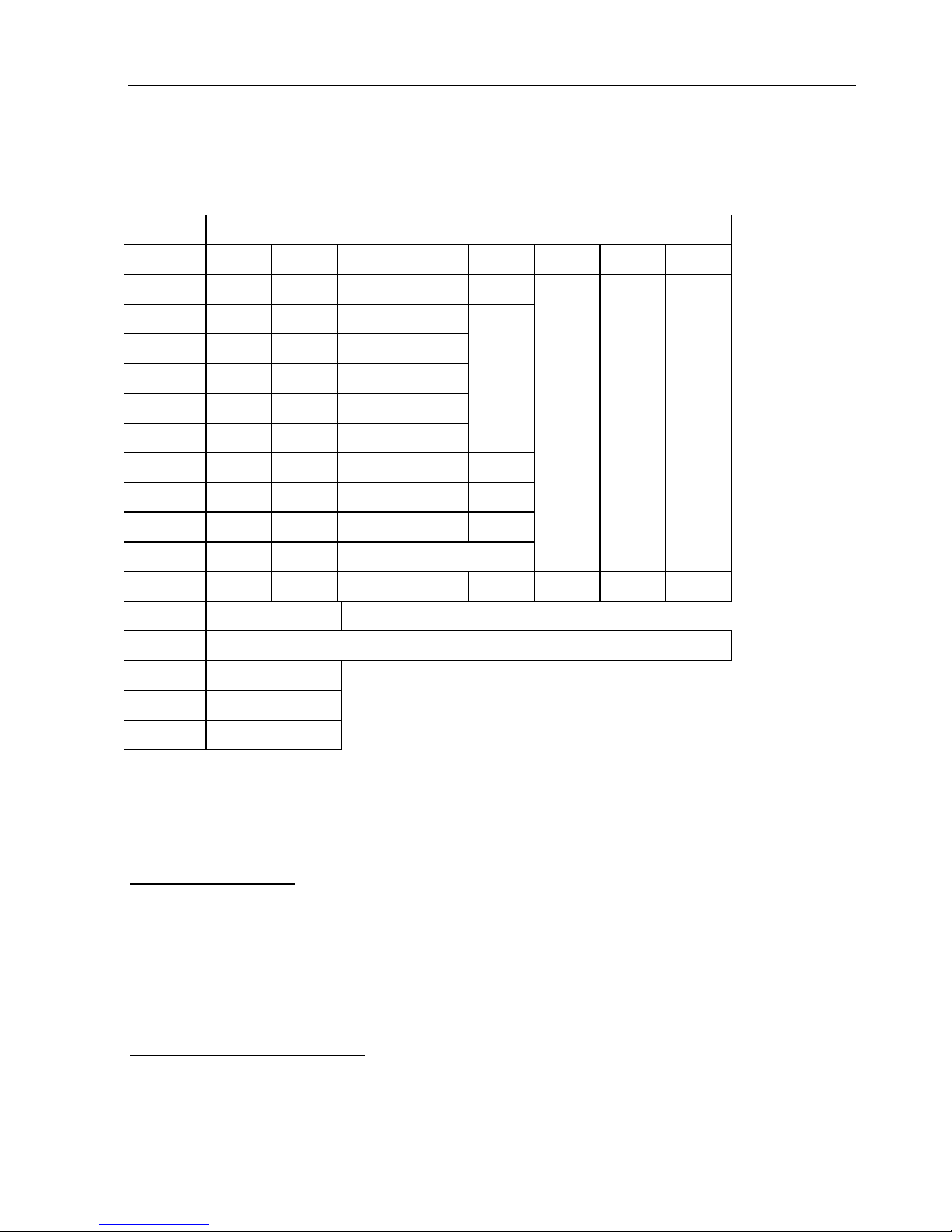
Each keypad key is used for entering letters, digits and other characters as follows:
No. of presses
Key 1 2 3 4 5 6 7 8
[1] . , ? ! 1
[2] A B C 2
[3] D E F 3
[4] G H I 4
[5] J K L 5
[6] M N O 6
[7] P Q R S 7
[8] T U V 8
[9] W X Y Z 9
[0] Space Zero
[*] ( ) / * : - + #
[#] Enable/Disable
[END] Cancel/ Return to previous screen/s without saving
[NEXT] Next char.
[BACK] Prev. char.
[ENTR] Save
1.5 Technical Specifications
Input voltage: 14VAC / 2A
Battery: 12VDC, Up to 7.5 Ah
Power Consumption
Control panel: 60mA
Keypads: 20mA
LCD keypad illuminating: 110mA
Siren: 2 outputs (Ext., Int.) up to 0.9 mA each
Power output: ~13.8VAC/up to 750mA
Operating temperatures (°C)
Control panel: -30 ~ +50
LCD keypad: 0 ~ +50
LED keypad: -10 ~ +50
Humidity 75% (Non-condensed)
Page 9

HUNTER-PRO Series Installation Guide 9
Zone Protection
Single or double EOL circuits
Other Protection
Continuous battery telephone line monitoring
Panel Outputs
Relay: N.O./N.C. 1A
Transistor outputs: 4, 200 mA max
Bell/Siren outputs: 2 with separate thermal fuses protection
Serial output: RS-232
Communication Channels
PSTN: Telephone interface and communicator
GSM: GSM-200 transmitter
SMS: SMS-100 module (via PSTN)
Ethernet: net4pro TCP/IP module
Radio: TRV/TRU-100: long range VHF/UHF transmitters
Page 10
10 HUNTER-PRO Series Installation Guide
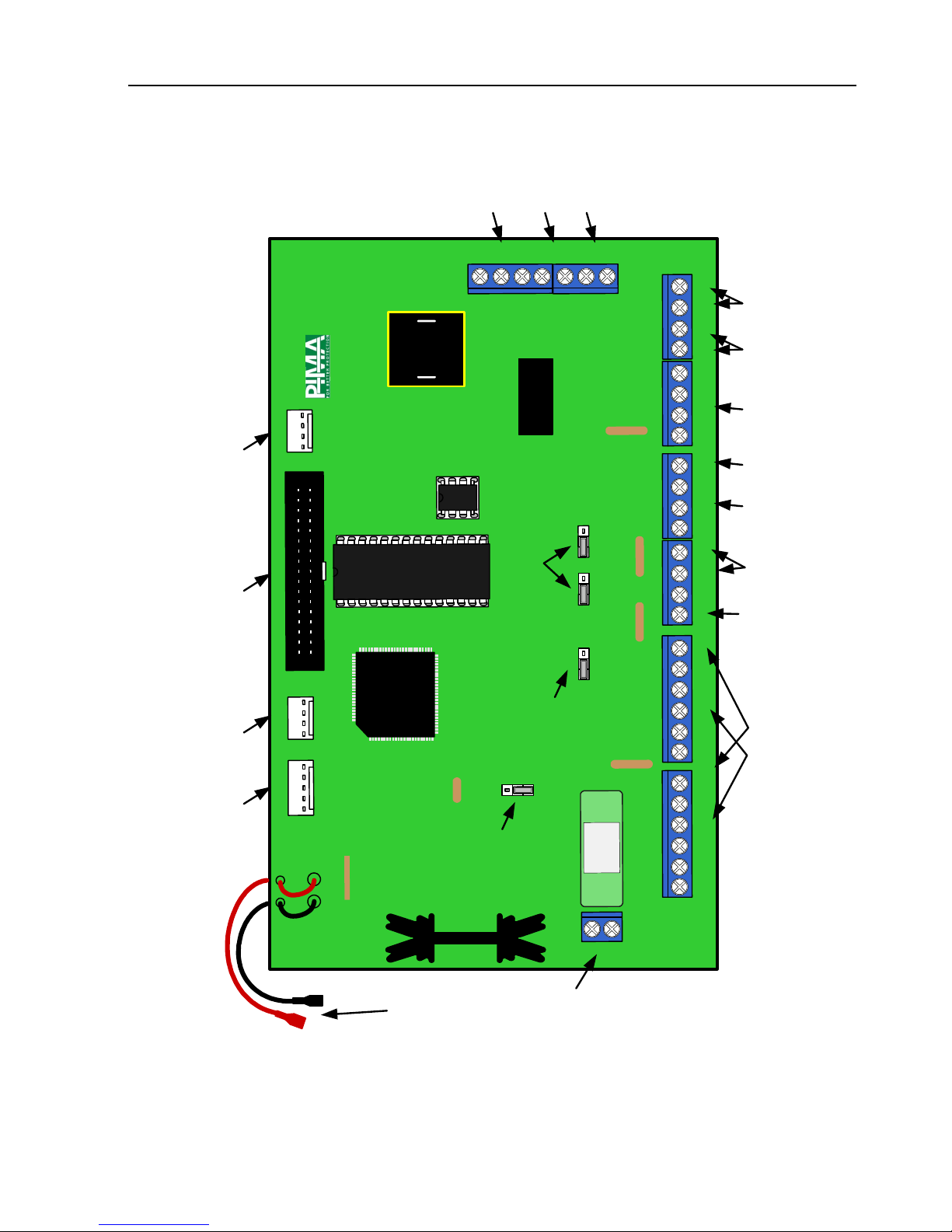
1.6 The Control Panel’s PCB
T
M
P
R
2
T
M
P
R
1
O
N
/
O
F
F
A
L
R
M
K
E
Y
P
A
D
E
X
P
A
N
S
I
O
N
C
A
R
D
S
E
R
I
A
L
K
E
Y
P
A
D
T
R
A
N
S
M
I
T
T
E
R
U
3
Z
1
Z
2
Z
3
Z
4
-
+
Z
5
Z
6
Z
7
Z
8
-
+
K
E
Y
-
E
x
t
I
n
t
C
N
.
O
N
.
C
-
S
I
R
E
N
S
R
E
L
A
Y
S
M
O
K
E
-
+
I
N
O
U
T
A
C
J
P
1
J
P
2
J
P
4
1
L
I
N
E
S
E
T
C
O
N
T
I
N
O
U
T
J
P
5
F
3
F
1
F
6
J
P
6
F
4
F
7
F
2
U
2
J
P
1
0
J
P
3
F
5
A
P
I
M
A
8
9
6
Z
O
N
E
S
1
2
3
4
A
U
D
I
O
1
2
3
4
5
6
7
8
9
10
11
121314
15
16
17
18
19
20
J
P
1
1
21
1
1
1
Figure 1. HUNTER-PRO Series PCB
1.6.1 Model & Version
The PCB/System model (832, 896 or 8144) is printed on a colored sticker on the
EPROM.
Page 11

HUNTER-PRO Series Installation Guide 11
• A model can be expanded to its limit number of zones and
users. For example, Hunter-Pro 896 cannot be expanded to
97 zones or 97 users
• The EPROM version and the system’s software version must
match, or a ‘System Error’ is displayed. For example, the
Hunter-Pro 896 EPROM cannot be used with a Hunter-Pro
832 software
1.6.2 Fuses
F5A - protects the PCB and the battery from high current (Thermo 5A/250VAC)
F6 - protects the PCB from an AC short (Fast 3.15A/250 V
1.6.2.1 Thermal Fuses to limit current:
F1 – Detectors power supply (750mA)
F2, F3 – Siren 1 and Siren 2 (1.1A)
F4 – Keypad power supply (750mA)
F7 – Radio transmitter protection (200mA)
1.6.3 Connections & Terminals
1 AC: Voltage Input
14VAC input supplied by a transformer
2 “+”, “-“: Connections to backup Battery
Red wire: “+” (positive) contact of the battery
Black wire: “-” (negative) contact of the battery
Connecting the battery inverted will damage the PCB
3 Z1–Z8: Zones terminals
Eight zone terminals for connecting dry contact detectors. Each zone can be protected
by a single or double EOL resistors (refer to “Connecting Zones”, section 3.1)
4 (+): Power Supply for DC Detectors
12V power supply for DC detectors: infrared, ultrasonic, beam etc.
5 KEY input
An input for momentary or on/off keys or Key fob for arming/disarming the panel
6 Ext., Int.: External & Internal Sirens terminals
Dedicated automatic thermal fuses (F2 and F3) for the sirens (see section 3.6)
7 RELAY output
An onboard relay that can be triggered in response to alarm/event and via telephone or
remote control
Page 12

12 HUNTER-PRO Series Installation Guide
8 SMOKE output
An output used to reset smoke/anti mask detectors. Normally, the output is switched
to (-). In alarm, it is disconnected for a predetermined period of time (See section
5.6.2). To reset manually:
9 KEYPAD terminals
There are 4 KEYPAD terminals:
“+” & “–“ for keypads power supply; Up to 8 monitored RXN-400/410 LCD keypads
can be connected simultaneously, as well as the wireless receiver I/O-WN and
I/O-8N/16/R expanders.
IN/OUT
for data transfer to/from the keypad. Thermal fuse F4 protects the 13.8 VDC
power supply.
10 ALRM and ON/OFF outputs
ALRM
– Is switched by default to (-) when alarm occurs;
ON/OFF
– Is switched by default to (-) when the system is armed.
These terminals have two conditions: disconnection or short to ground. They can serve
as indicators to auxiliary units and to system or alarm status, or other modes (see
section 5.9.1).
11 TMPR1 and TMPR2: Input terminals for Tampers switches
Input terminals for tamper switches in detectors and cases. The switches can be
connected with EOL resistors. They can also serve as monitoring indicators for 24 hour
zones, panic buttons etc. TMPR 2 input can serve as zone #9 (see section 3.2.2).
12 LINE: Telephone line terminal
The telephone line is used both for dialing and receiving remote programming calls. If
the telephone line is used by other accessories, it is recommended that the system will
be the first to connect to the line.
13 SET: Telephone set terminal
Two outputs for connecting appliances such as answering machine and fax. All devices
will be disconnected by the system when it requires the telephone line.
14 AUD IN, AUD OUT, CONT: Microphone and Voice Unit
Connectors
CONT is used for controlling voice unit (VU-20N) and microphone (MIC-200). Only one
device can be connected at a time.
AUD IN is used for 2 purposes: receiving information from audio resources and sending
SMS messages using SMS-100.
15 TRANSMITTER: Radio, GSM-200 & SMS-100 unit
TRANSMITTER is a connector to PIMA long-range radio transmitters TRU/TRV-100, to
the cellular transmitter GSM-200 (see section 3.12) and to the SMS-100 PSTN
SMS unit.
Page 13
HUNTER-PRO Series Installation Guide 13
GSM-200 and SMS-100 cannot be installed simultaneously
To connect a radio transmitter other than PIMA’s use TX-1000 adaptor
16 KEYPAD: Technician keypad Molex terminal
A terminal for connecting a technician keypad (using the TC-3 cable)
17 Expansion Cards terminal
Connector to OUT-1000 and EXP-PRO UNIV expansion cards
18 SERIAL terminal
Used for connecting to TCP/IP communication.
19 JP5, JP10: Siren Type Jumpers
Set the siren type in conjunction with JP6 (See section 3.5).
20 JP6: Siren Power Source
See section 3.5
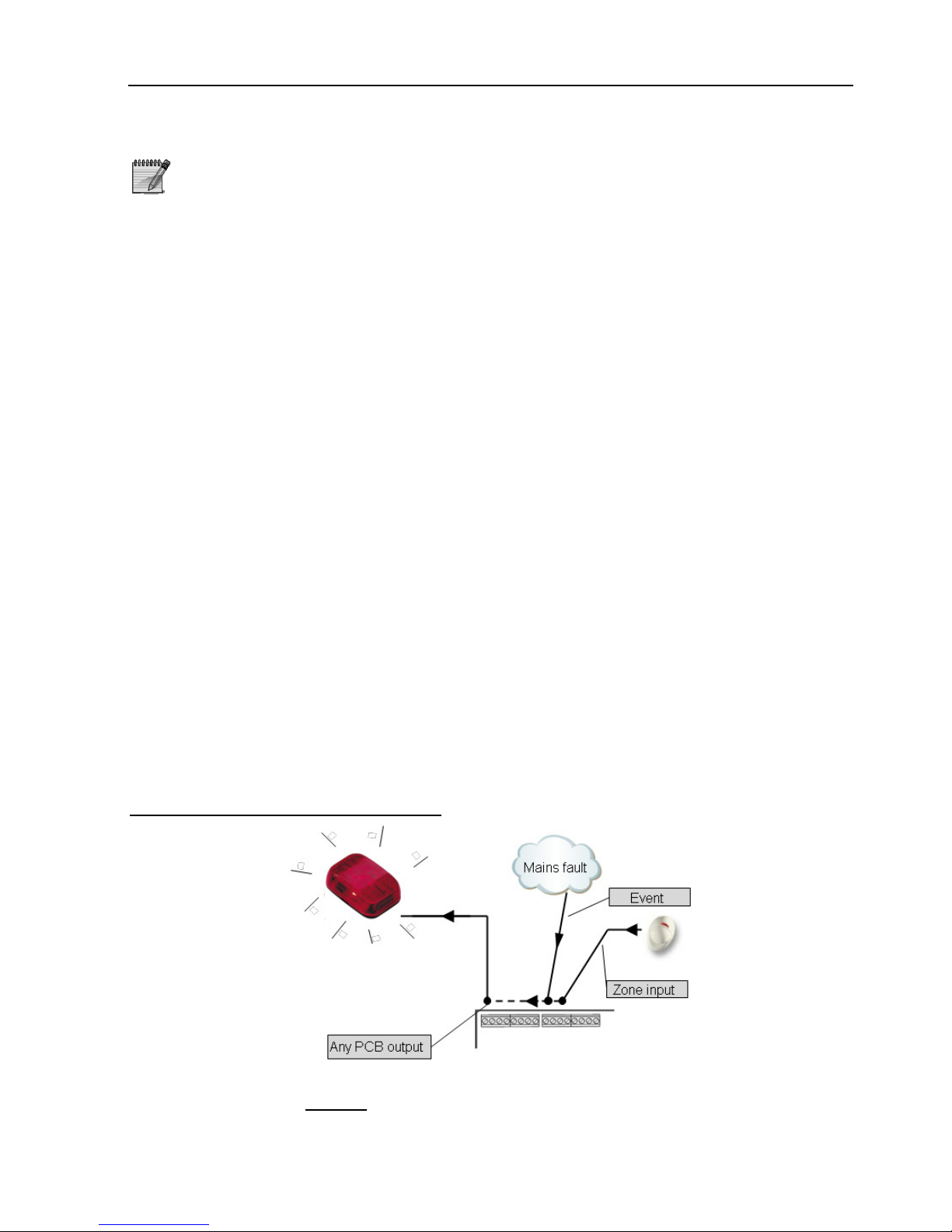
1.7 PCB Outputs and Output Types
Unlike in previous PIMA alarm systems such as the Hunter-Pro 32, the responses to
events in the Hunter-Pro series are determined through a set of new functions called
‘output types’. These are made of zone types and system events (more than 30 in all)
that trigger the PCB outputs.
A PCB output can only be triggered by one output type, but an output type can trigger
one or any of the PCB outputs.
Regardless of the printed output name, there is no limit as to what device can be
connected to which output: a bell/bulb can be connected to the RELAY output or to the
ON/OFF output, as long as the output type that should trigger it is linked to the right
PCB output.
Hunter-Pro 32 mode of operation
An Alarm signal is received in the panel. Subject to the programmed response of the
zone it came from, a physica
l PCB output is tripped. For example, the Burglary zone
(type) is programmed to trigger the onboard relay and therefore, an alarm from any
Burglary zone will trip the relay.
Page 14
14 HUNTER-PRO Series Installation Guide
In the same manner the mains fault event can also trigger the relay. The only
disadvantage is when only one zone type or event needs to trigger the relay: the
technician should then verify that no other event or zone type is programmed to trigger
the same output.
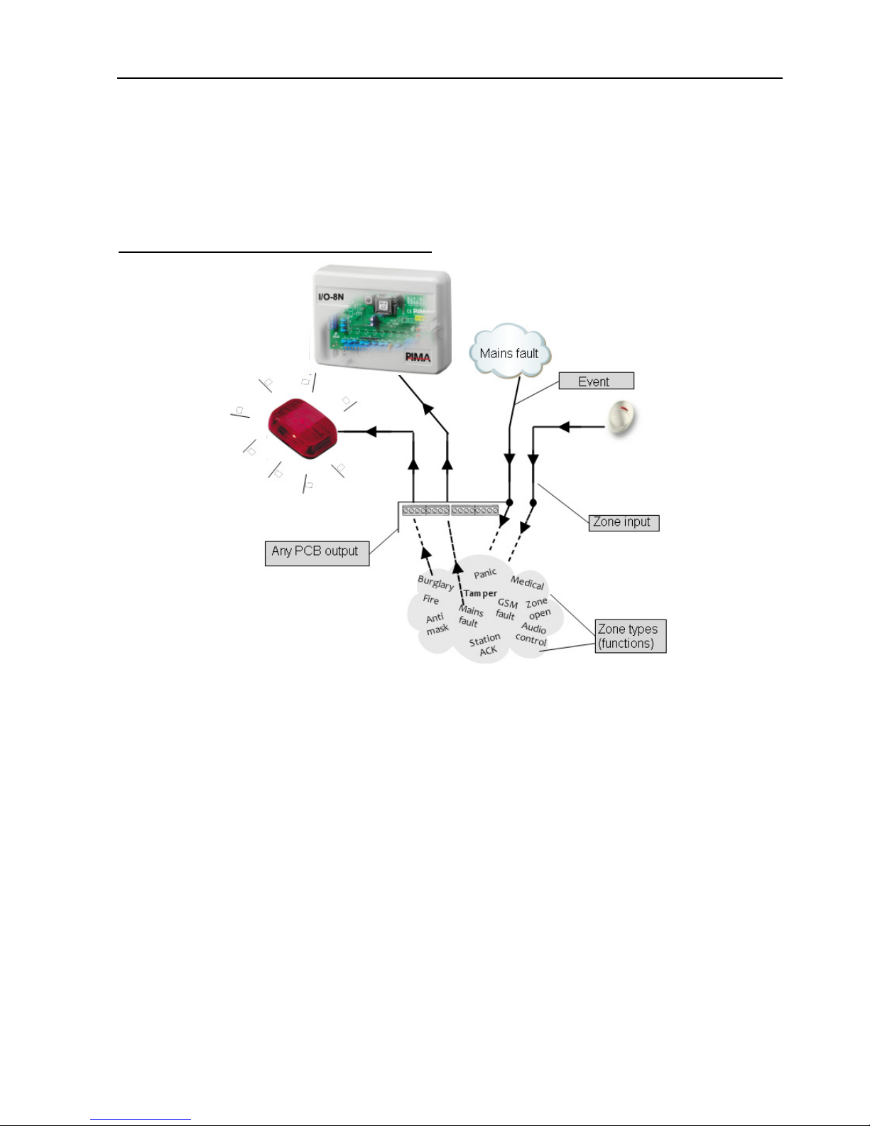
Hunter-Pro series mode of operation
The HUNTER-PRO series introduces a new concept, in which functions called ‘output
type’, which represent various events or zone types in the system, are linked to the
PCB physical outputs.
Through the ‘Output configuration’ menu (#7) an output type is linked to a certain PCB
output (Relay, Ext. Siren, Smoke, Alarm, etc.) and by that, whenever an event that
relates to this ‘output type’ occurs, the PCB output that is linked to is tripped. An
example scenario goes like this:
A Panic signal (from a Panic zone or the keypad or a wireless device) is received in the
panel. ‘Panic’ is one of the 30 and more ‘Output types’. The Panic output type was
previously linked to output #2 in I/O-8N expander and since so, it triggers that output
and will continue to do so anytime a Panic alarm is generated.
In this mode, each physical output can be tripped by one and only one ‘output type’.
For example, Alarm and Low Battery output types, cannot both trip the ON/OFF
onboard output.
This makes the HUNTER-PRO series a very versatile system in handling and responding
to alarms and events. It is for the technician to decide how to handle each one.
Among the new ‘output types’ are: Panic, Fire, Anti mask, GSM fault, Medical,
Station ACK. See section 5.9.2.
Page 15
HUNTER-PRO Series Installation Guide 15
CH. 2. PARTITIONING
2.1 Introduction
A partition is a sub-division of the system, made of several zones. By using partitions
you can control user access authorizations. Each partition can be controlled by one or
more keypads and a user can be given a code that will allow him to control only a
specific partition in a specified time frame.
HUNTER-PRO series can have up to 16 partitions and 8 keypads (i.e. monitored
keypads). A keypad can control one or more partitions.
2.2 Examples
2.2.1 Example A
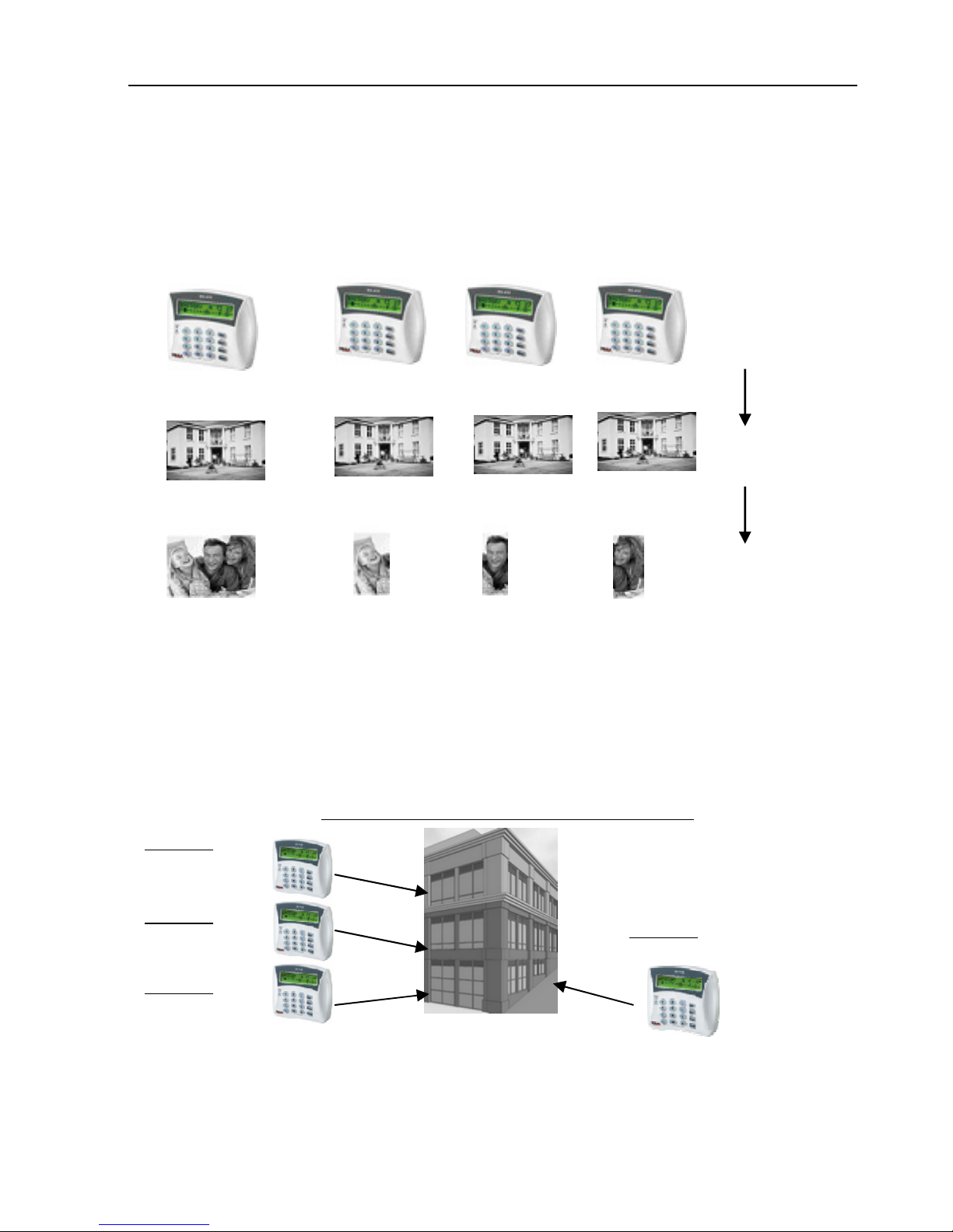
Figure 2. Implementing partitions - Example A
In example A, keypad 1 controls all 3 partitions and is used by all 3 users.
2.2.1.1 Common Application for Example A
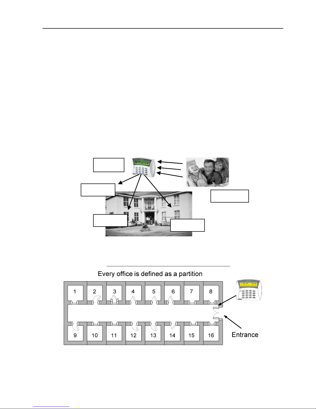
Figure 3. An office facility divided into rooms/partitions
A floor in an office building has 16 rooms. Each room is programmed as a partition and
can have different User Codes/Remote Controls/TAGs for arming/disarming the system.
A single keypad is installed at the entrance of the hallway. In this case, the keypad will
display the entire system’s status.
Partition 1
Partition 2
Partition 3
Keypad 1
Users 1, 2, 3
Page 16
16 HUNTER-PRO Series Installation Guide
A detector located next to the entrance and allocated to all partitions protects the
entrance, as soon as all partitions are armed. This zone will be unarmed as soon as the
first partition is disarmed.
2.2.2 Example B
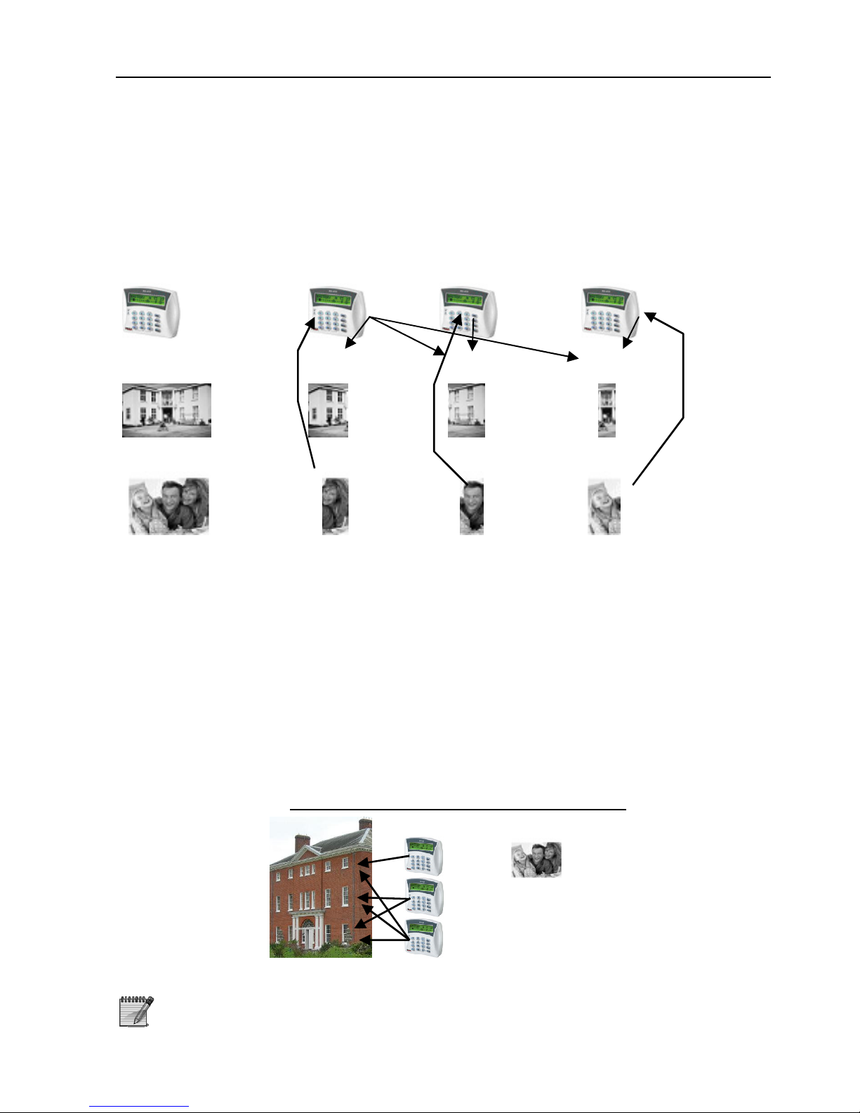
......
.....
.....
Figure 4. Implementing partitions - Example B
The system is divided into X partitions, each partition is controlled by its keypad/s
(defined in “System Installation/Keypads Setup/Partitions for RKD”). A User Code has
access authorizations based on partition/s (defined in User Menu/Code/User
Codes/Partitioning), e.g. User 1 can only activate Partition 1 & 5. That implies for
arming/disarming too.
A keypad displays the status of its authorized partition’s only.
2.2.2.1 Common Application for Example B
Figure 5. Common application for partitions
An office building is divided into 4 departments with different entrances and different
working hours:
Control Panels (up to 8 monitored)
Partitions
(up
to 16)
Users (up to 96)
Control Panel 1
Partition 1
User 1
Control Panel 2
Control Panel 3
User 2 User 3
Partition 2
Partition 3
Keypad 3:
Management
floo
r
Keypad 2
:
Production
floo
r
Keypad 1
:
Storage (part of
1
st
floor)
Keypad 4
: Store
(part of 1
st
floor)
Part. 3
Part. 2
Part. 1
Part. 4
Page 17
HUNTER-PRO Series Installation Guide 17
Each department has its keypad: Keypad 1 controls partition 1 (store/storage floor),
Keypad 2 controls partition 2 (production floor), Keypad 3 controls partition 3
(management floor), Keypad 4 controls partition 4 (storage/store floor)
Employees (i.e. users) can have access only to their partition, or to several partitions.
2.2.3 Example C
......
......
.....
Figure 6. Implementing partitions - Example C
A private home has 3 floors: the first floor is defined as Partition #1, the second floor is
Partition #2, and the third floor is Partition #3.
Keypad #1 controls all #3 partitions (& displays their status)
Keypad #2 controls partition #2 only (& displays its status only)
Keypad #3 controls partition #3 only (& displays its status only)
User #1 can control partitions #1, #2, #3 using keypad #1
User #2 can activate partition #2 with keypads #1, #2
User #3 can activate partition #3 with keypads #1, #3
2.2.3.1 Common Application for Example C
Figure 7. Common application for partitions
A user can control several partitions using a single code
Control panel #3
Control panel #2
Control panel #1
Partition #3
Partition #2Partition #1
User #1
User #2 User #3
3rd floor: part. 1
2
nd
floor: part. 2
1
st
floor: part. 1
Users can be given different access
authorization levels with regard to
keypad/floor/partition
Page 18
18 HUNTER-PRO Series Installation Guide
CH. 3. CONNECTING ZONES & ACCESSORIES
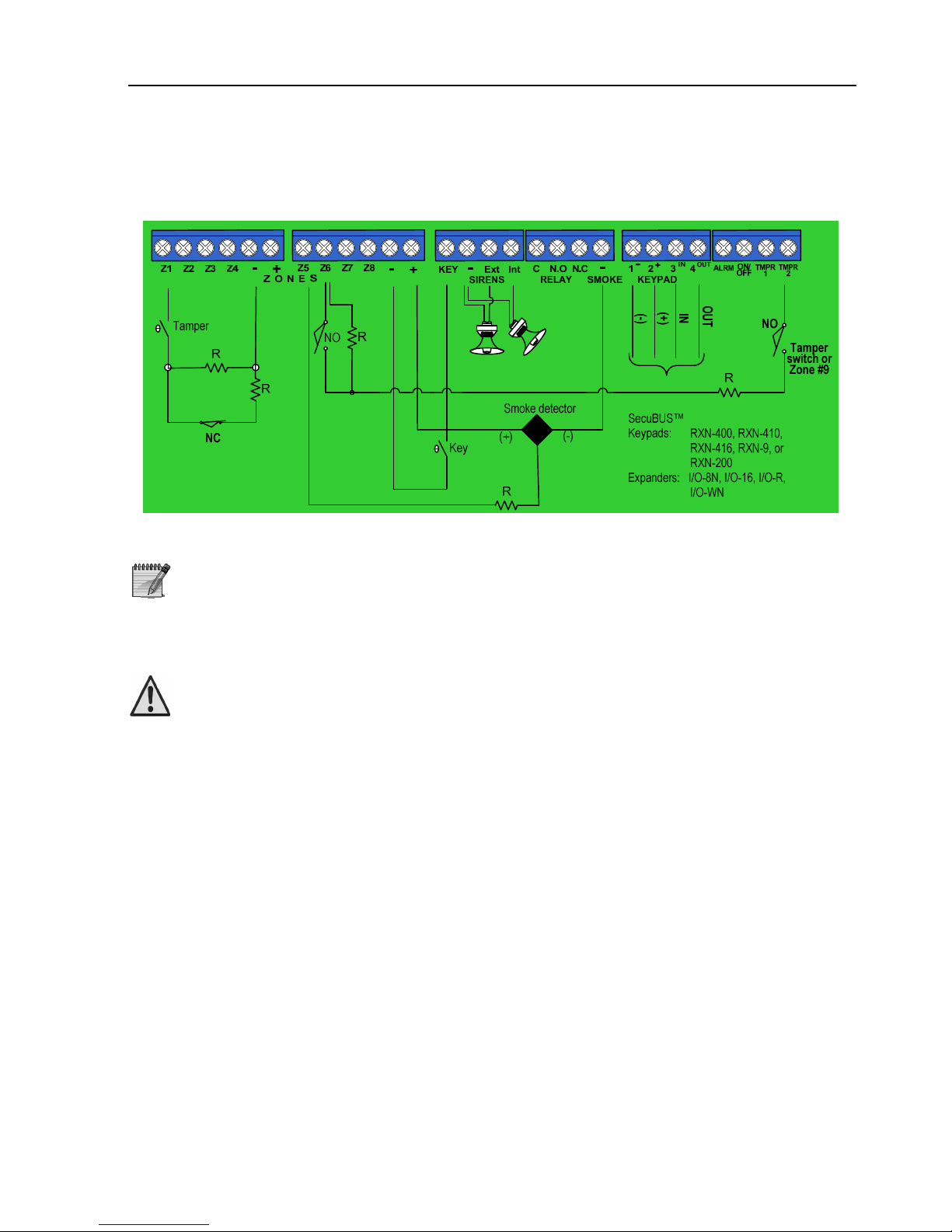
Connect the accessories according to the following scheme and instructions:
Figure 8. Connections scheme
The overall length of the wirings connected to the SecuBus™ cannot
exceed 500 meters (call PIMA support when longer distance is required)
The SecuBus™ uses PIMA proprietary protocol
3.1 Connecting Zones
Disconnect all power supply prior to installation!
3.1.1 Zones Inputs
The system’s default zone protection is without EOL (End of Line) resistor/s. A Zone
protection can have either one or two EOLs.
The detectors’ type and whether they are connected with or without EOL resistors are
set in “Zone Characteristics” (see section 5.4.1). The number of EOL resistors is set to
all EOL zones and is programmed in “General Parameters” (section 5.7). For zone
programming refer to sections 5.4 & 5.7.
3.1.2 Connecting a Detector (without EOL)
Connecting N.C. detector with no EOL resistor is done according to the following
diagram. The tamper can be connected in one of two ways:
A. To the TMPR input on the system’s PCB.
B. As a “24 hours” separate zone.
Page 19
HUNTER-PRO Series Installation Guide 19
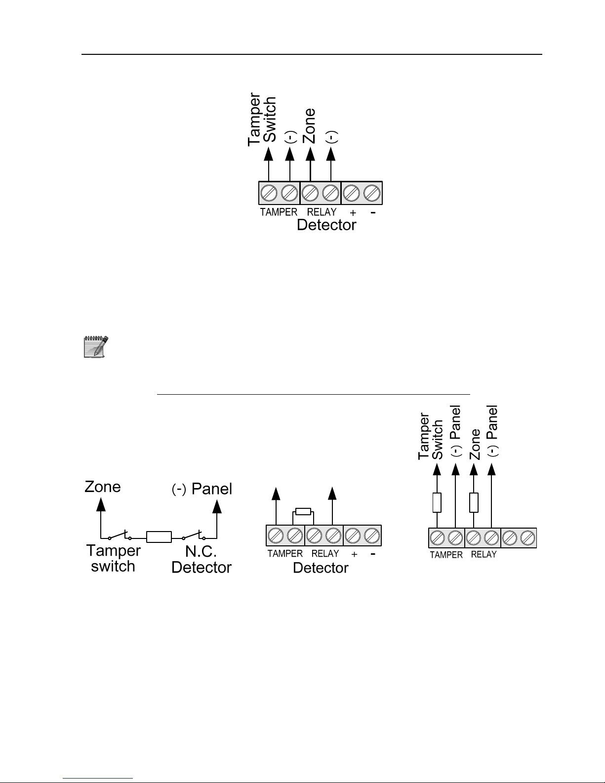
Figure 9. Connecting DEFENDER PIR without EOL resistor
3.1.3 Connecting a Detector using a Single EOL
Connecting N.C. detector with a single EOL resistor is done according to the next
diagrams. The tamper needs be connected to the TMPR input on the control panel’s
PCB or as a “24 hours” separate
When connecting N.O. detector, configure the zone input
accordingly (see section 5.4.1(
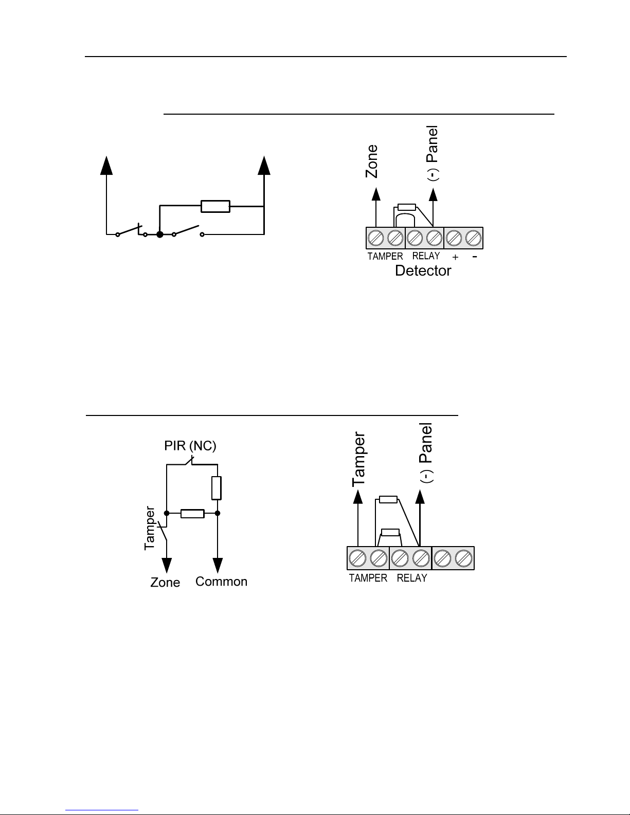
3.1.3.1 Connecting EOL resistor to N.C. DEFENDER PIR
Zone
() Panel
+
Detector
Figure 10. One EOL resistor
connected to N.C. detector
Figure 11. One EOL
resistor in serial to the
relay and the tamper
Figure 12. Separate
connections for the
relay and the tamper,
each with its EOL
resistor
Page 20
20 HUNTER-PRO Series Installation Guide
3.1.3.2 Connecting EOL resistor to N.O. DEFENDER PIR Detector
Zone
(
-)
N.O.
detector
Tamper
switch
Figure 13. One EOL resistor
connected to N.O. detector
Figure 14. One EOL resistor in serial to the
relay and the tamper
3.1.4 Connecting a Detector using 2 EOL resistors
Apart from the tamper connection there is no difference whether the detector is a N.O.
or N.C. one. Connecting a detector with two EOL resistors is done according to the
next diagrams.
2 EOL Resistors with DEFENDER PIR (N.C. or N.O.) & Tamper (N.C.)
+
Detector
Figure 15. 2 EOL resistors with
an N.C. detector and tamper
Figure 16. 2 EOL resistors
connected to a tamper in serial to
the relay output
Page 21
HUNTER-PRO Series Installation Guide 21
3.2 Connecting Zone Expanders
The HUNTER-PRO series has 8 onboard zones. These can be expanded by using
different expansion cards and add-on devices. The following is a brief scan of the zone
and outputs expansion options. A detailed installation description is found further on.
EXP-PRO
UNIV
Local expansion card with 8 hardwired zones. These zones will always be
numbered 9-16. See further on page 23.
I/O-8N 8 zones and a relay. It connects to the KEYPAD connections of the
control panel’s PCB.
I/O-16 Expansion card with 16 zones and a relay. It connects to the KEYPAD
connections of the control panel’s PCB.
I/O-WN Wireless expansion card with wireless receiver. The receiver supports 32
wireless zones as well as 24 key fobs, for arming/disarming, send duress
code and trigger the onboard output.
OUT-1000 Expansion card with 8 outputs for triggering external units. See page 31
for connecting instructions.
I/O-R Expansion card with 8 relays for operating CCTV and spotlights etc. The
relays can be triggered directly or in respond to alarm. See more on
page 26.
When connecting both hardwire and wireless expanders, the system
first numbers the hardwire zones and only then the wireless zones.
Within the line expanders, the system first numbers the EXP-PRO
UNIV expander, if installed. Only afterwards the other expanders are
numbered.
The expanders connected through the BUS are numbered in
ascending order according to their ID
3.2.1.1 Max. no. of expanders
I/O-8N expanders:
In Hunter-Pro 832: 3 expanders in total, 2 if EXP-PRO UNIV is installed
In HUNTER-PRO 896: 11 expanders in total, 10 if EXP-PRO UNIV is installed
In Hunter-Pro 8144: 16 expanders in total, 15 if EXP-PRO UNIV is installed
I/O-16 expanders:
In Hunter-Pro 832: A single expander
In HUNTER-PRO 896: 5 expanders
In Hunter-Pro 8144: 8 expanders
3.2.2 Tamper #2 Input Configured as Zone #9
The onboard TMPR #2 input can serve as a zone (#9), giving no expander is
connected to the system and TMPR #2 is set accordingly in “General Parameters” (see
parameter “2”, in General Parameters First Screen, page 69).
Page 22
22 HUNTER-PRO Series Installation Guide
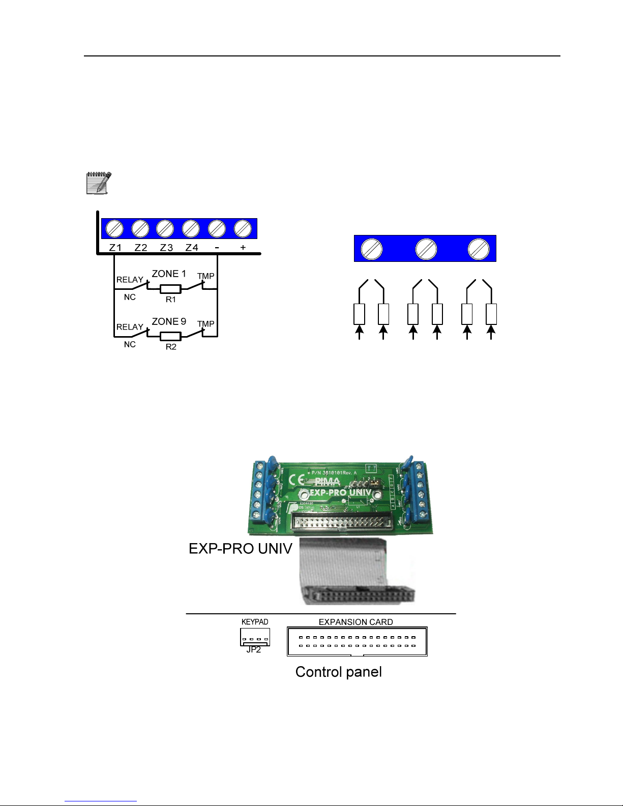
3.2.3 Zone Doubling
The 8 onboard zones can be doubled to 16 by using different resistors, so zone #1
input is used by both zone #1 and zone #9, zone #2 input is used by both zone #2
and zone #10 etc., up to zone #16.
Zone doubling cannot be enabled if any expander is connected to the system
Control Panel
Z1 Z2 Z3
10KΩ 1/4 w
5.1KΩ 1/4 w
Z1 Z9 Z2 Z10 Z3
Z11
3.2.4 EXP-PRO UNIV
1. Connect the card to the system case, using the 2 supplied screws.
2. Use the supplied flat cable to connect the card to PCB’s Expansion Card socket
(see the following drawing)
3. To configure the EXP-PRO UNIV, refer to section 5.3.2.
Figure 17. Connecting EXP-PRO UNIV to the PCB
Page 23
HUNTER-PRO Series Installation Guide 23
3.2.5 I/O-8N, I/O-16, I/O-R
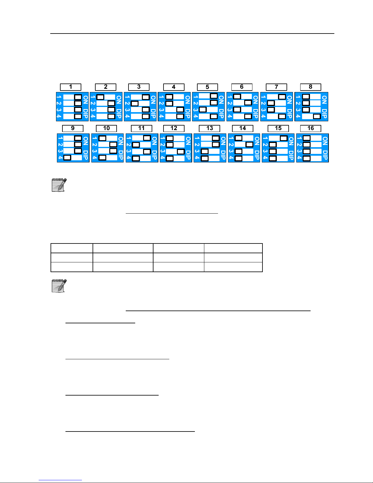
Each card must have a unique ID, determined by its dip-switch:
2 cards cannot have the same ID
I/O-8N IDs must be successive. The I/O-16 IDs are 1, 3, 5, 7
or 2 ,4 ,6 etc.
3.2.5.1 Expanders’ Numbering
Under the HUNTER-PRO series system, every 8 zones must have a unique ID;
Therefore, I/O-16 takes two IDs. Here’s an example for numbering few expansion
cards:
Card #1 Card #2 Card #3 Card #4
I/O-8N I/O-16 I/O-8N I/O-16
ID=1 IDs=2 and 3 ID=4 IDs=5 and 6
It is recommended to connect all the accessories GND (-) to the system’s
PCB. That includes power suppliers.
3.2.5.2 Examples of expanders and zone numbering:
Single I/O-8N/R card:
If EXP-PRO UNIV is installed: is numbered 17-24
If EXP-PRO UNIV is not installed: is numbered 9-16.
Two I/O-8N/R cards (16 zones):
If EXP-PRO UNIV is installed: are numbered 17-32
If EXP-PRO UNIV is not installed: are numbered 9-24.
Two I/O-16 cards (32 zones)
If EXP-PRO UNIV is installed: are numbered 17-48
If EXP-PRO UNIV is not installed: are numbered 9-40.
Single I/O-WN card (32 wireless zones):
If EXP-PRO UNIV and 2 I/O-8N cards are installed (32 zones in total) the I/O-
WN zones will be numbered 33-64.
Page 24
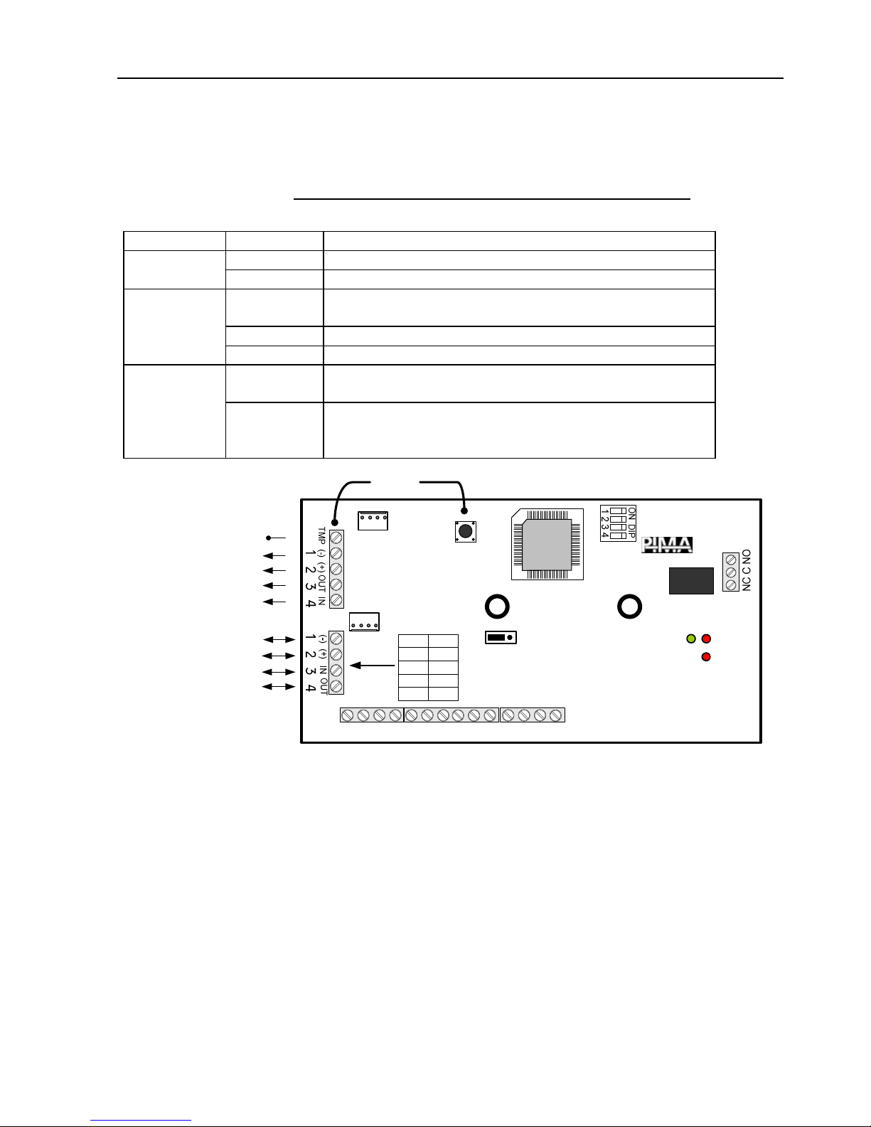
24 HUNTER-PRO Series Installation Guide
Follow the information in the next pages for connecting expansion cards. To program
the number of expansion cards, refer to section 5.4.
3.2.5.3 I/O-8N: 8 zones & a relay expansion card
I/O-8N has three LEDs described in the following table:
LED STATUS DESCRIPTION
ON Card works OK RUN (Green)
OFF Voltage fault
Flashes Normal mode. LED flashes while data is transferred from
the control panel to the card
ON Communication fault (disconnection)
MASTER
DATA (Red)
OFF Communication fault (short)
Flashes once
a second
Data fault (expander does not receive communication
from control panel)
FAIL (Red)
Flashes
twice a
second
Communication fault (check in the display)
RUN
MASTER
DATA
Connection to control
panel and Secubus™
Connection to other
expanders (max. 3)
To external Tamper
POWER SUPPLY
TECH KEYPA D
Parallel
connection
1-
23
-
45-67-8
+
+
I/O-8N
-V 1 -
+V 2 +
3 IN
4 OUT
Panel Exp.
JP1
SC
Tamper
EOL values
jumper
OUT
IN
Relay
FAIL
Figure 18. I/O-8N PCB
Page 25
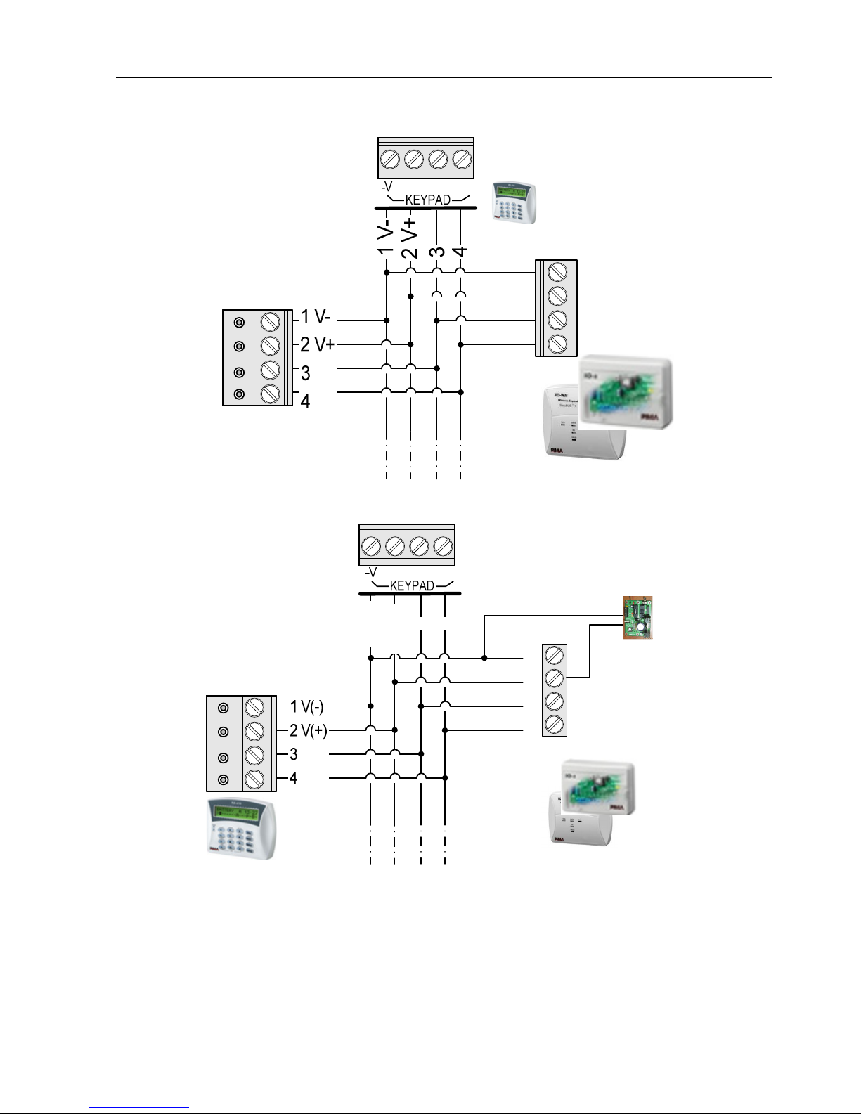
HUNTER-PRO Series Installation Guide 25
+V IN OUT
Control panel
BUS
KEYPAD
ID=2
I/O8N/16,
I/OW
RXN-410
ID=1
Figure 19. Connecting external expansion cards on control panel BUS
1V(-)
2V(+)
3
4
+V IN OUT
Control panel
I/O-8N/16/W
RXN-410
ID=1
(-) (+)
IN
OUT
PS-2 Power
supplier
(-)
(+)
Figure 20. Connecting external expansion cards to control panel BUS with external
power supplier PS-2
Page 26
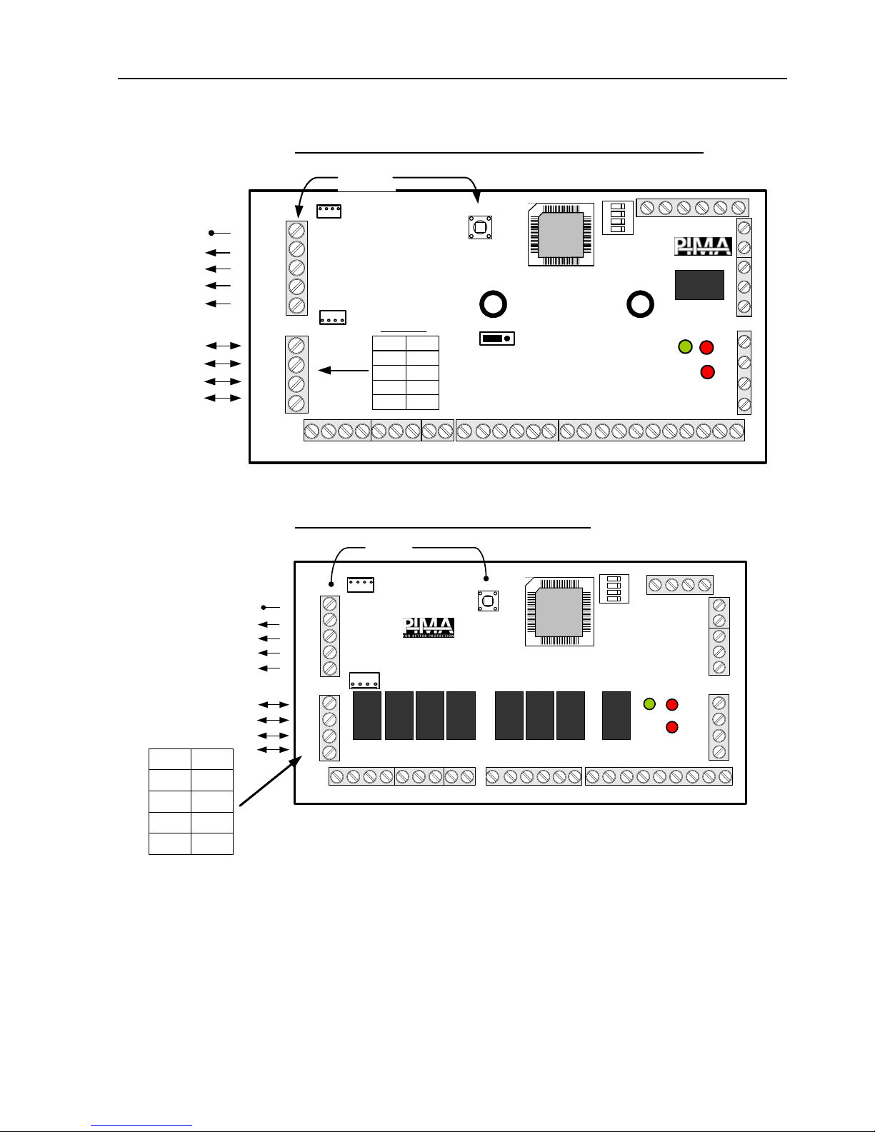
26 HUNTER-PRO Series Installation Guide
3.2.5.4 I/O-16: 16 zones & a relay expansion card
NC C NO
Parallel
connection
TMP (-) (+) OUT IN
RUN
MASTER
DATA
FAIL
+ + + +
(-)
(+)
IN OUT
Wiring
-V 1 -
+V 2 +
3 IN
4 OUT
Panel Exp.
1
2
3
4
5678++9101112131415
-
-- - - - -16-
I/O-16
- -
JP1
SC
Jumper to set EOLs
Tamper
POWER SUPPLY
TECH KEYPAD
1 2 3 4 1 2 3 4
OUT
IN
- - -
Expander ID
ON DIP
1 2 3 4
Relay
Connection
to control
panel and
SecuBus™
Connection
to other
expanders
(max. 3)
To external
Tamper
Figure 21. I/O-16 PCB
3.2.5.5 I/O-R: 8 relays expansion card
Tamper
switch
To control panel &
Secubus™
To other
expanders
(up to 3)
To
external
tamper
Parallel
connection
Panel
RELAY
COM
1
NC NO NC NO NC NO NC NO NC NO NC NO NC NO NC NO
RUN
MASTER
DATA
FAIL
-----
++++
ON DIP
1234
I/O-R
----
POWER SUPPLY
TECH KEYPAD
OUT
COM
2
COM
3
COM
4
COM
5
COM
6
COM
7
COM
8
TMP (-) (+) OUT IN
(-) (+)
IN OUT
1234 1234
RELAY
RELAY
RELAY
RELAY
RELAY
RELAY
RELAY
IN
Exp.
(-V) 1 (-)
(-V) 2 (+)
3 IN
4 OUT
Figure 22. I/O-R PCB
Page 27
HUNTER-PRO Series Installation Guide 27
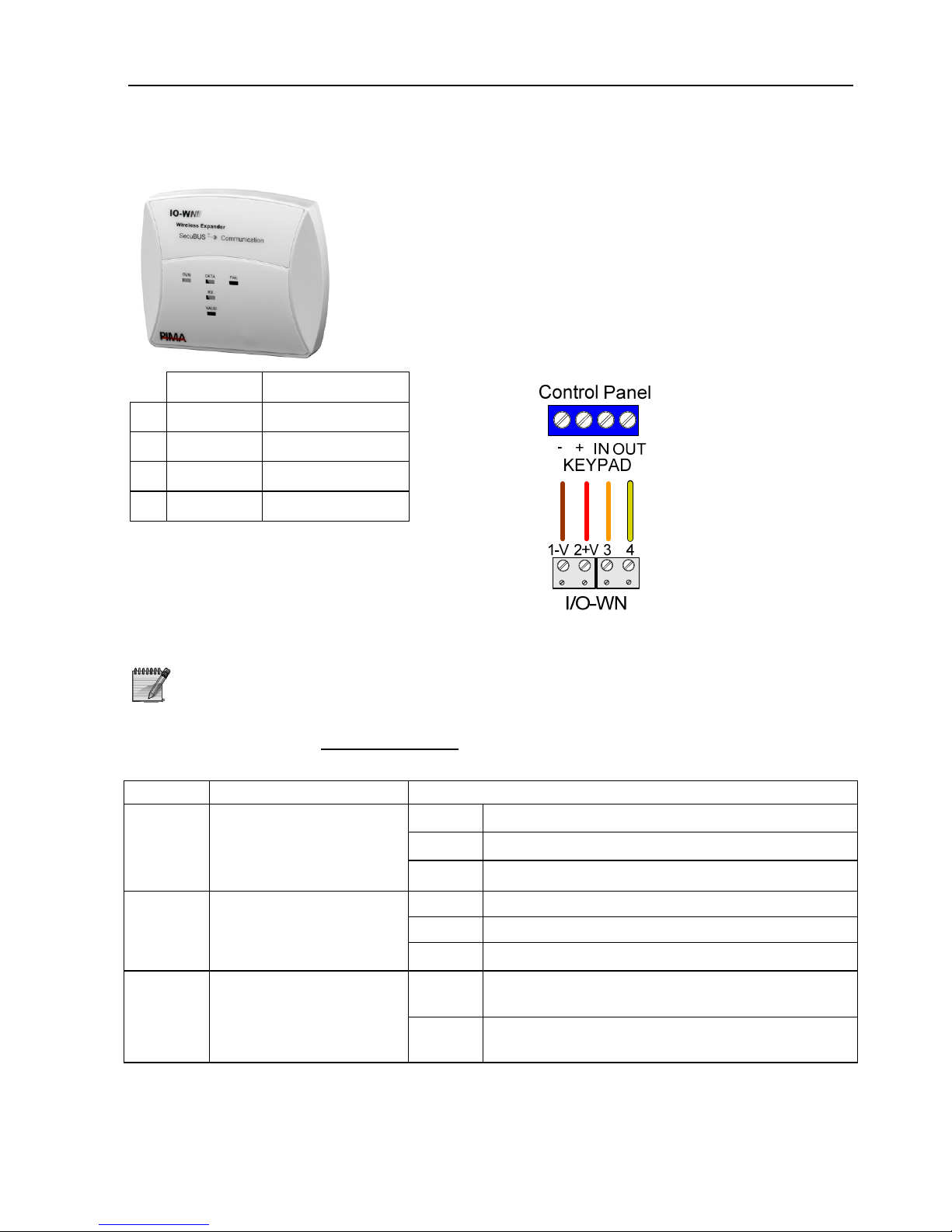
3.2.6 I/O-WN
I/O-WN is a wireless receiver that integrates with
HUNTER-PRO Series. It enables the connection of
wireless detectors (such as PIR, Reed Switch etc).
See section 3.2 for more details.
I/O-WN connects to the PCB’s KEYPAD connections. See
the next drawing and the table that follows.
I/O-WN Control Panel
1 -V -
2 +V +
3 OUT IN
4 IN OUT
Figure 23. I/O-WN wiring
For further information regarding the I/O-WN, refer to its
installation guide
3.2.6.1 I/O-WN LEDs
The I/O-WN has 5 LEDs, described in the following table:
LED Description Status
ON Card is operating and connected to voltage
OFF Fault in the connection to voltage
RUN
(Green)
I/O-WN operation and
connection to voltage
Flashes Fault in card voltage
ON Communication fault
OFF Short in communication wiring
DATA
(Red)
I/O-WN connection to
control panel
Flashes Data connection is OK
Flashes The card is receiving transmission from a
wireless device
RX
(Red)
Receiving transmission
OFF No transmission is received from any
wireless device
Page 28
28 HUNTER-PRO Series Installation Guide
LED Description Status
Flashes Signal has been acquired
VALID
(Green)
Acquiring a signal
from wireless devices
OFF Signal has not been acquired (no
reception from the wireless device)
One No valid frame is received from the panel
2 long
flashes
No ACK is received from the panel
3 long
flashes
The card is not programmed
FAIL
(Red)
Communication failure
with the control panel
4 long
flashes
General/Fatal error. Occurs when
no communication is received for one
minute
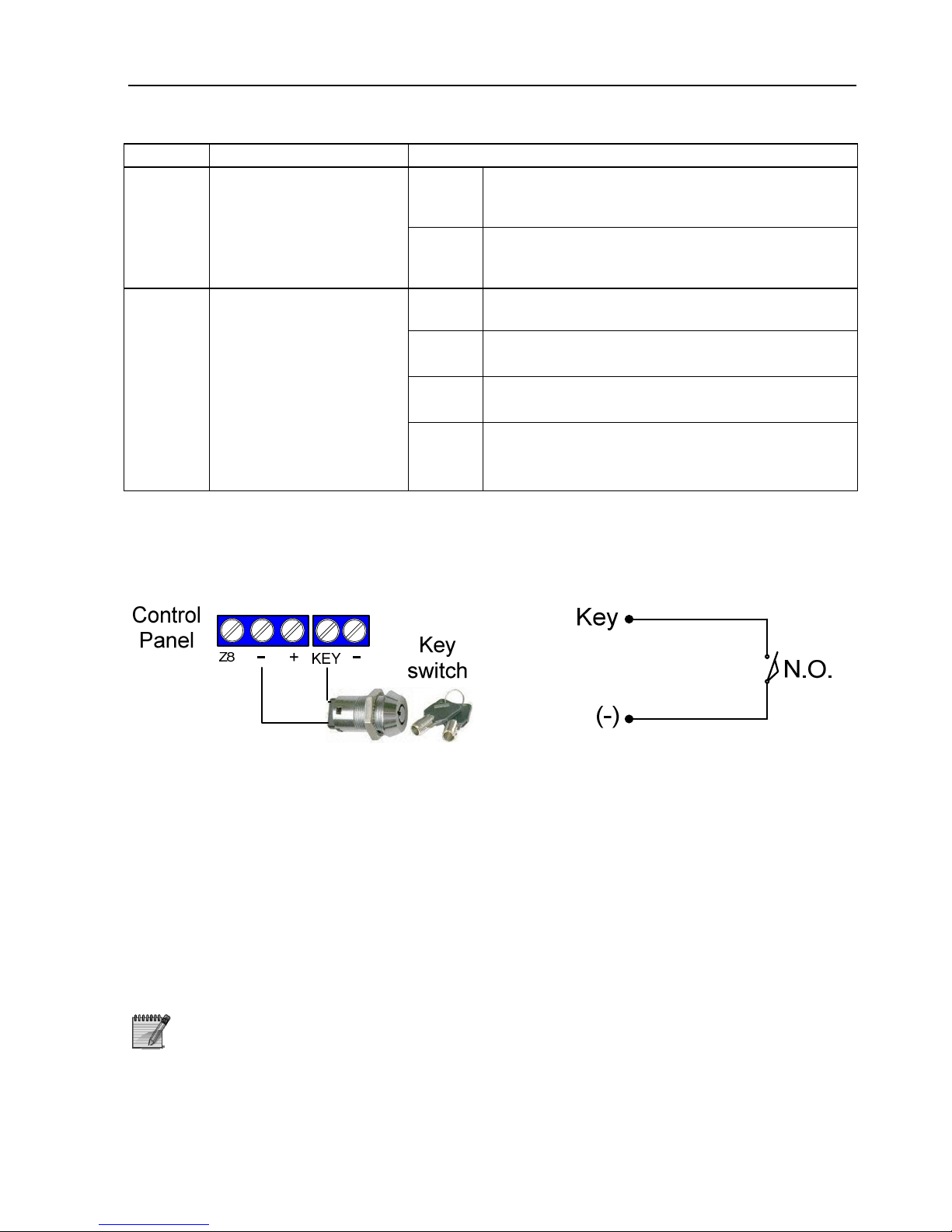
3.3 Connecting a Key
Connect a key or Key fob according to the next diagrams. The key can be set as
momentary or ON/OFF switch. The default is momentary.
Figure 24. Connecting a key
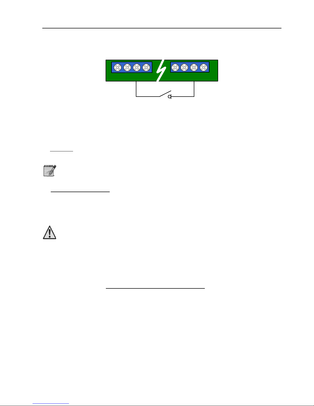
3.4 TMPR1, TMPR2: Tamper Switches
In addition to cases and boxes protection, the tampers can be used for panic buttons,
sensors (temperature, pressure etc.) with dry contact outputs and more.
Connect the tamper switch between the TMPR1/TMPR2 connections and ground (–).
TMPR1 input is connected to the tamper switch onboard the PCB.
A 10kΩ resistor at the terminal input on the PCB provides a short/disconnect indication,
since the tamper switches are NC type.
1. By default, TMPR1 & TMPR2 inputs are enabled and without EOL
(see section 5.7.1).
2. To use tamper #2 as zone #9, see section 5.7.1
Page 29
HUNTER-PRO Series Installation Guide 29
Tamper switch
Control Panel
T
M
P
R
2
T
M
P
R
1
O
N
/
O
F
F
A
L
R
M
Z
7
Z
8
-
+
Figure 25. Connecting a tamper switch
3.5 Connecting Sirens
Two siren types can be connected to the HUNTER-PRO series control panel:
1. AC Siren
: This is usually a horn or 8Ω speaker, driven by the control panel’s
built-in oscillator.
The AC siren can produce 2 different tones (frequencies). The tones
are predetermined. See section 5.4.2
2. High current DC Siren
: This can be a bell or any other high current device
with internal oscillator. The control panel supplies 1.1A for activation only.
The sirens outputs are split: JP5 is associated with “Ext.” (External) output; JP10 is
associated with “Int.” (Internal) output.
1. Different siren types cannot be connected simultaneously
2. The external siren cannot be activated without activating
the internal one
3.5.1 AC Siren
The siren is connected between the terminal block outputs (Ext. or Int.) and GND (-).
Make sure the siren is not set as DC (see section 5.7.1).
3.5.1.1 Setting a different siren tone
The siren’s sound is produced by a built-in oscillator and programmed in “Zone
Responses” menu. When zone type is programmed, a different siren tone to different
zone types can be set (see section 5.4.2).
Page 30
30 HUNTER-PRO Series Installation Guide
3.5.1.2 Settings for the AC siren
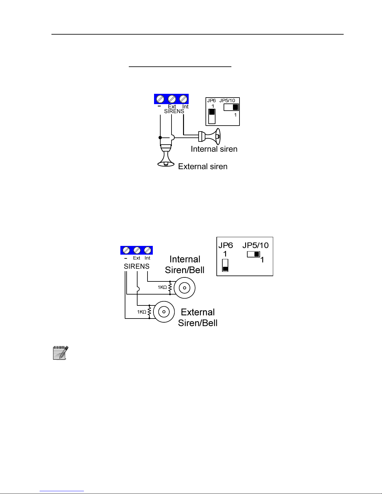
In “General Parameters”, set “D” to “-”. This will set the siren to AC (see section 5.7.1).
Set JP5, JP10 & JP6 to short pins 2 & 3.
Figure 26. Connecting AC Siren
3.5.2 DC Siren
Connect the siren between the Ext. or Int. terminals and “-”.In “General Parameters”
screen, set “+” under “D” (see section 5.7.1). This will set the siren as DC.
Set JP5 & JP10 to short pins 2 & 3 and JP6 to short pins 1 & 2.
Figure 27. 2 DC/Bell siren wirings
When using a DC siren, it is recommended to connect a 1kΩ EOL
resistor to eliminate noises
The following table describes the various siren installation possibilities:
Page 31
HUNTER-PRO Series Installation Guide 31
Opt Siren Type JP5/
JP10
JP6 Parameter ‘D’ in
“General” menu
1 Speaker: Panel generates a tone. Uses
unregulated voltage
2-3 2-3 Set to “-”
2 High current self-activating bell
(protected by 1.1A thermal fuse): Uses
the panel’s battery
2-3 1-2 Set to “+”
3.6 Relay Output
The relay can be used for activating external devices (light, CCTV etc.) and is activated
response to alarm/fault, when entering relay code in the keypad and via telephone.
To program Relay Code refer to “HUNTER-PRO SERIES User Manual”. To program relay
trip time see section 5.6.2.
If the relay timer is programmed to zero, when triggered, it
remains tripped until a code is entered or the system is disarmed
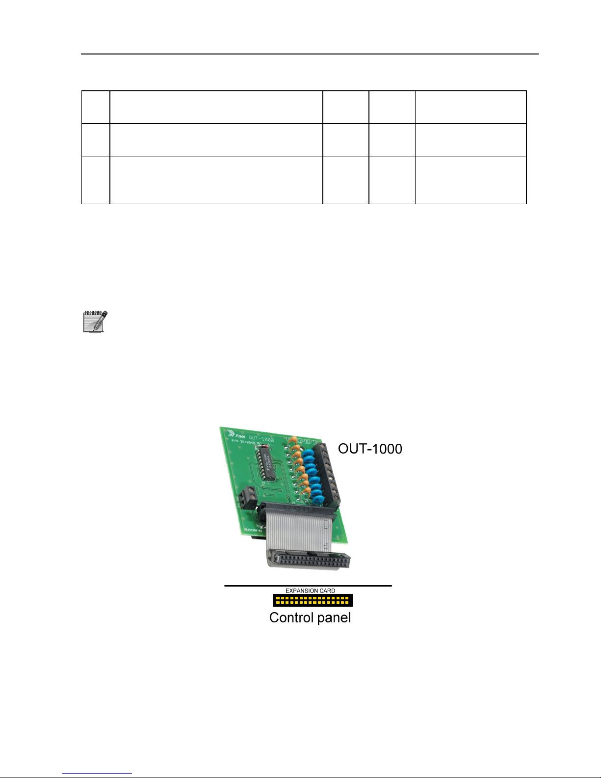
3.7 OUT-1000: Local Outputs Expansion Card
OUT-1000 is an 8 TTL outputs card, used to activate peripheral devices such as CCTV,
alarm triggered lights, etc. Use the cable to connect the control panel’s EXPANTION
CARD connector to connect the OUT-1000.
Figure 28. Connecting OUT-1000 to control panel
Page 32
32 HUNTER-PRO Series Installation Guide
3.8 Keypads
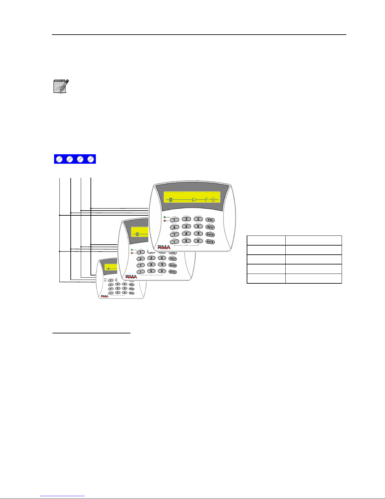
Reminder: The system can monitor up to 8 keypads
Connect the keypad’s wires to the PCB KEYPAD terminals. The 4 keypad wires
must be separated from other wires
3.8.1 RXN-400 & RXN-410 LCD Keypads (Incl. ACE)
Control panel
Keypad #1
Keypad #2
Keypad #8
….
.
.
1 JUN 08 12:40
RXN-410
1 JUN 08 12:40
RXN-410
-
+INOUT
KEYPAD
1 JUN 09 12:40
RXN-
410
Figure 29. Connecting 8 LCD keypads
Keypads Control Panel
- -
+ +
OUT IN
IN OUT
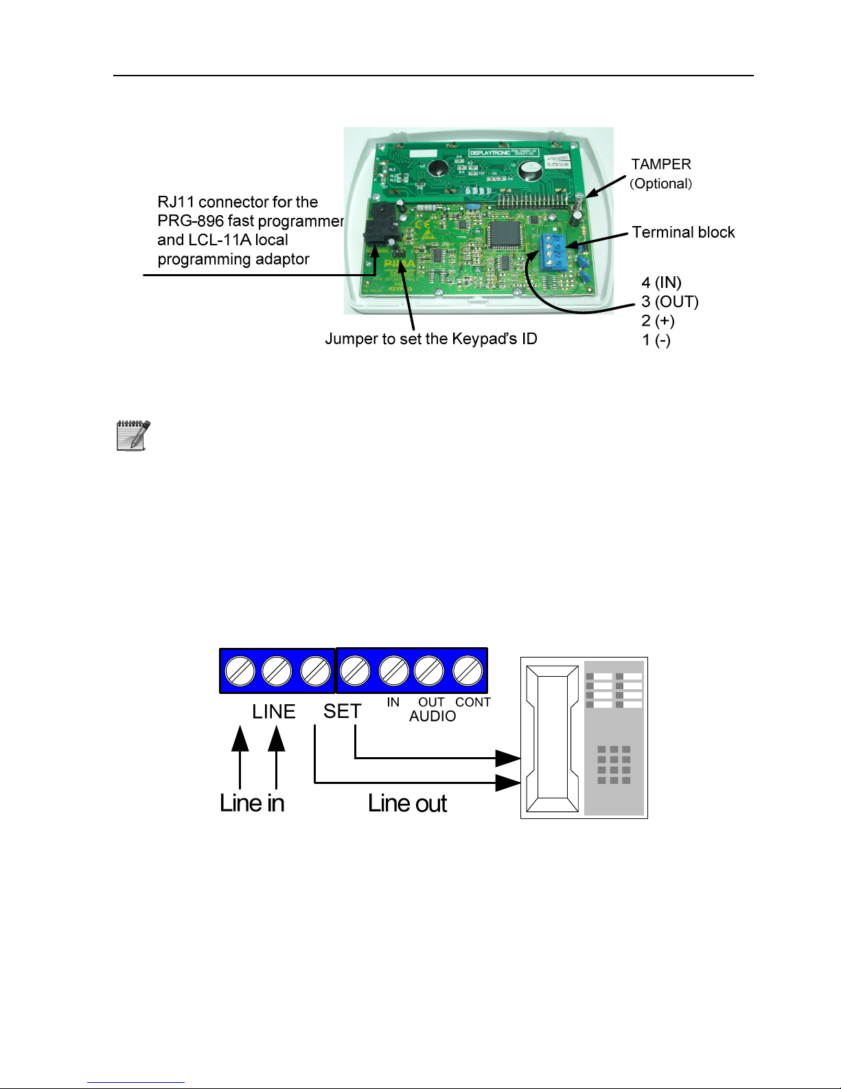
To set the keypad’s ID:
1) Short JP1 pins 1 & 2
2) The message onscreen should be: “Enter new ID: 0”. Enter the new ID (1 to 8)
3) Short JP1 pins 2 & 3 back.
4) Repeat the process above for the remaining keypads. Note that each keypad must
have a unique ID and that numbering must be consecutive
Page 33
HUNTER-PRO Series Installation Guide 33
Figure 30. LCD keypad without back cover
1. If keypad supervision is not required, the number of keypads
connected to the system (see section 5.3.4) and all keypads’ IDs
should be set to zero
2. Up to 8 keypads can be connected to the system, whether they
are supervised or not
3.9 Telephone Line and Devices
The system should be the first device connected to the telephone line (through the
LINE terminals). Other devices (telephone set, answering machine, etc.) need to be
connected to the SET terminals to enable “line snapping”.
When alarm occurs, these devices will be disconnected so the system can dial and
receive calls. When calls are over the line will be reconnected to the SET terminals.
Figure 31. Telephone connections
3.10 VKD-1: Virtual Keypad
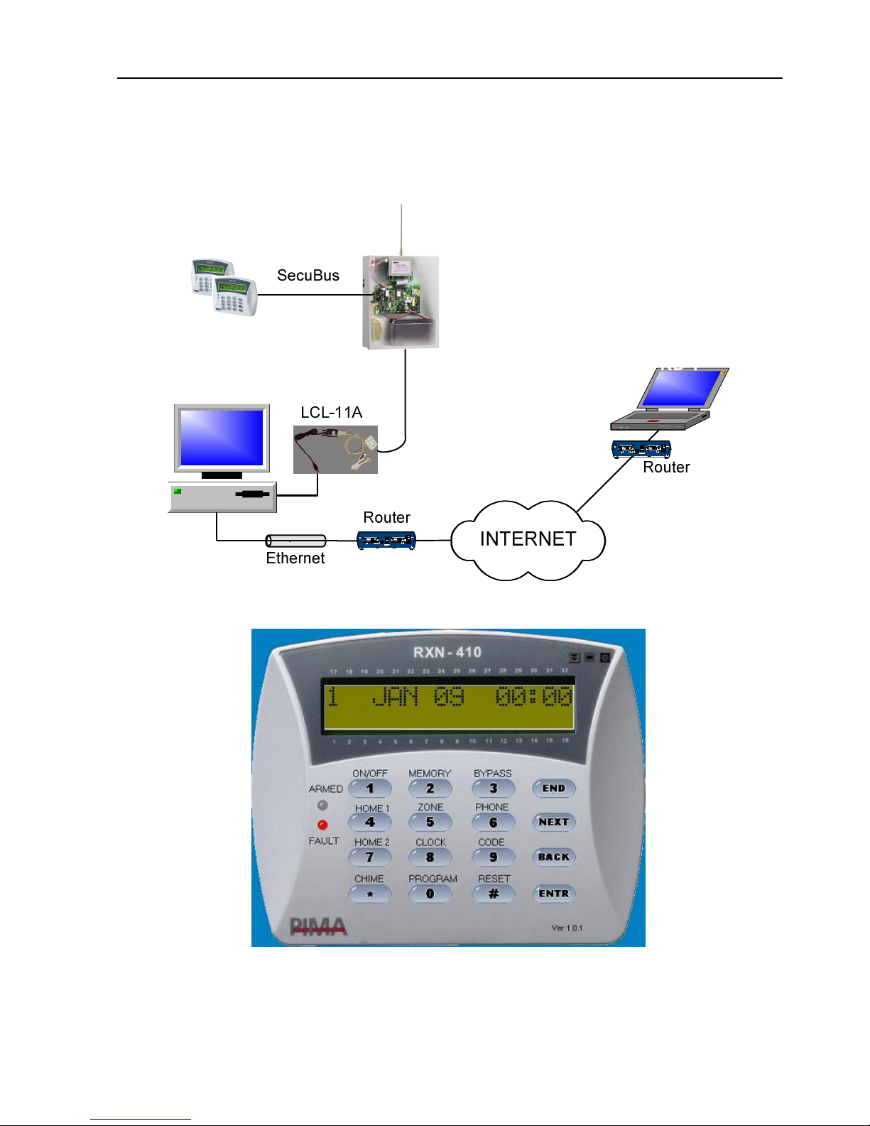
VKD-1 is PIMA’s software for creating a virtual LCD keypad and connecting it to any
PIMA control panel, locally (via cable) or remotely, via the internet. With VKD-1 you
can view and control the system just as if you use a real LCD keypad connected to the
system.
Page 34
34 HUNTER-PRO Series Installation Guide
The VKD-1 can operate any PIMA control panel directly from your PC, is easy to install
(does not require any special panel settings), and suitable for new and existing PIMA
panels.
SD
Cisco 1720
BRI
S/T
CONSOLE
AUX
WIC 0 OK
OKB2B1
WIC 1 OK
DSU
CPU
LNK100FDX
S3
LOOP
LP
SD
Cisco 1720
BRI
S/T
CONSOLE
AUX
WIC 0 OK
OKB2B1
WIC 1 OK
DSU
CPU
LNK100FDX
S3
LOOP
LP
Figure 32. VKD-1 connection diagram
Figure 33. VKD-1 on the desktop
The VKD-1 installation guide can be downloaded from PIMA website at:
www.pima-alarms.com
Page 35

HUNTER-PRO Series Installation Guide 35
3.11 TRV/TRU-100 Long Range Radio Transmitters
3.11.1 Mounting Guidelines
Following these guidelines will minimize RF interference:
Do not mount the Panel close to a metal wall or ceiling
Make sure you leave enough space for the atenna between the metal box and
the ceiling
Install the antenna at a distance from the Control Panel’s wiring
Mount the antenna after you complete all other installations
Make sure the antenna is not folded and is vertical
Close the HUNTER-PRO SERIES metal box when performing transmission tests
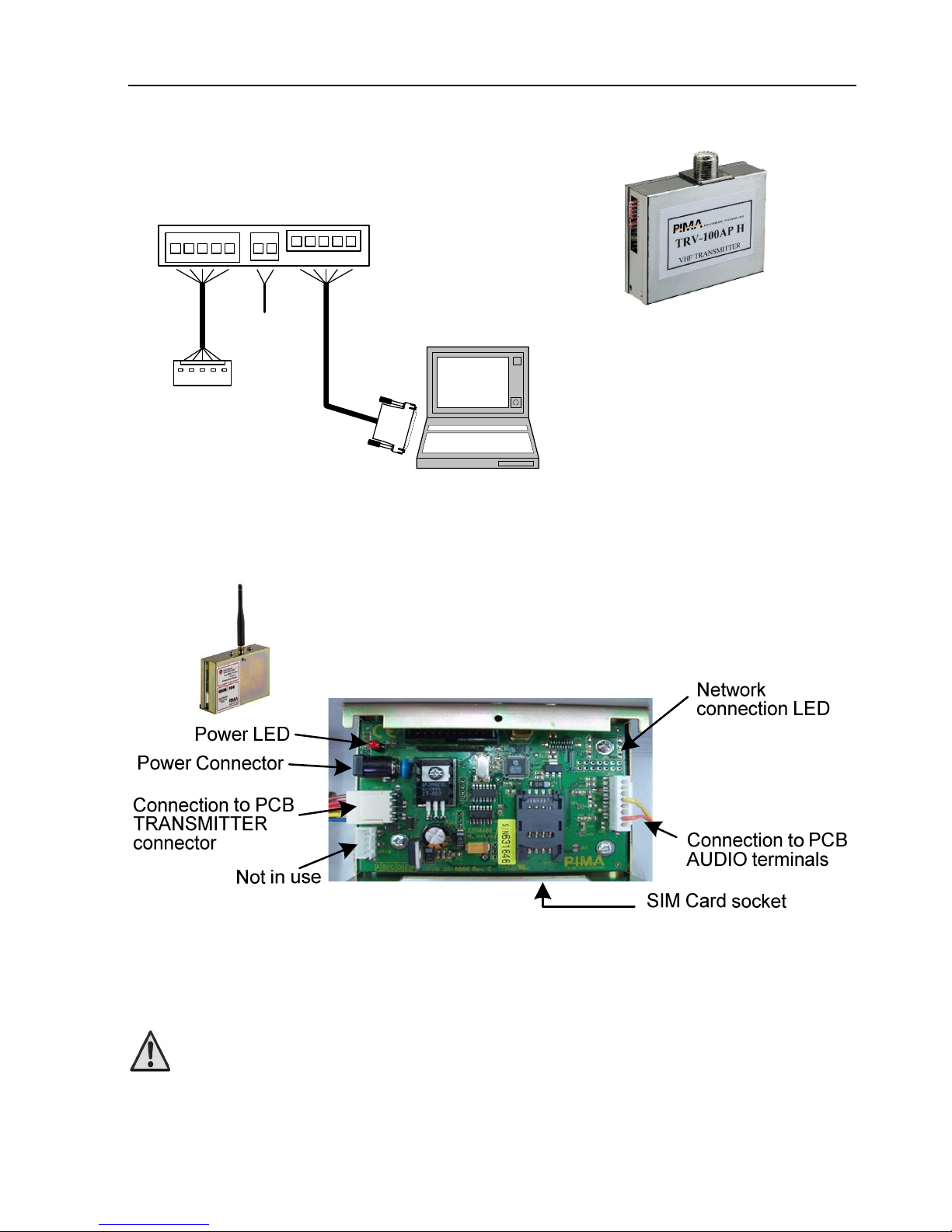
3.11.2 Connecting the Transmitter
The TRV/TRU-100 can transmit in 2 frequencies
1. Mount the HUNTER-PRO SERIES metal box on a stable surface/ wall
2. Screw the transmitter’s 4 screws (at the base) to the system box. Make sure
the screws are tightened; else, the transmitter’s range can be reduced.
3. Connect the antenna to the transmitter. Make sure the antenna is straight.
4. Make sure the 5-pin cable is connected to the transmitter’s Molex (named: “To
the system” on the transmitter’s sticker.)
5. Connect the other end of the 5-pin cable to the male Molex, placed on the
Control Panel’s upper left side (named “Transmitter” on the Control Panel.)
To use the second frequency only:
Follow the pervious 1 to 5 instructions, and then:
1. Connect the 2-pin cable to the transmitter’s F2 Molex (named F2 on the
transmitter’s sticker.)
2. Connect the other end of the 2-pin cable to the control panel depends on the
desired transmitter operation:
To constantly work with the second frequency:
Connect it to (-) output on the Control Panel.
To work with 2 frequencies according to event type:
1. Connect it to one of the system’s outputs, such as ALARM or ON/OFF to one of the
PGM outputs: AL/ON/OFF/RELAY.
2. Program these outputs in “Outputs” menu (see section 5.9). The related
parameters need to be programmed in “Communication Configuration” menu (see
section 5.5.4).
Page 36
36 HUNTER-PRO Series Installation Guide
TRV/TRU-100
Control Panel
To the
System
F2
Program
DPR-44
TRANSMITT ER
PC with Comax
2 Channels
Controller
Figure 34. TRV-100
transmitter
Figure 35. TRV/TRU-100 Connections
3.12 GSM-200: Cellular Transmitter
Figure 36. GSM-200 PCB
To prevent RF interference:
Do not mount the system close to a metal roof or wall
Check that there is enough space for the antenna between
the system and ceiling
Keep wiring as distant as possible from antenna
Install the antenna only after system installation is done
Make sure the antenna is not folded
Page 37
HUNTER-PRO Series Installation Guide 37
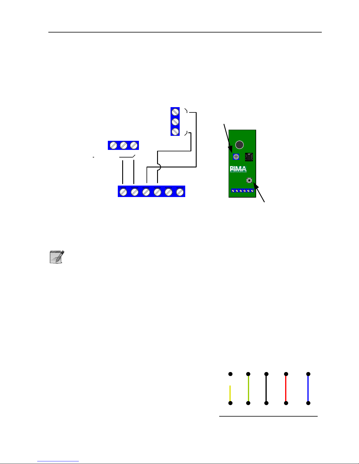
3.13 MIC-200: Microphone Unit
1. Connect MIC-200’s CON to the control panel’s CONT terminal.
2. Connect MIC-200’s OUT to the control panel’s AUD IN terminal.
3. Connect MIC-200’s (-) and (+) to the detectors’ power source.
Control
Panel
Tamper
switch
Trimmer
MIC200
+
-
Z O N E S
Z8
MIC-200
(-)12(+)CON OUT TAMP
AUDIO
CONT
IN
OUT
(-)12(+) CON OUT TAMP
Figure 37. Connecting MIC-200 to the control panel
3.14 VU-20N: Dual Message Voice Unit
3.14.1 Single message programming
A zone that is supposed to trigger the VU-20N should be linked to ‘Audio device’ output
type. Since any output in the Hunter-Pro series can be triggered by any output type,
the VU-20N can be connected to any of the outputs, providing that the ‘Audio device’
output type was linked to it.
1. Navigate to a desired output (#7) and link the
‘Audio control’ output type to it
2. Press ENTR twice to Polarity and mark ‘-’
under ‘P’
3. Navigate to ‘Zone responses’ (#2), pick the
Zone Type that will trigger the VU-20N
‘Message 1’ and mark ‘+’ under ‘M - Activate
Audio’. Make sure the output trim time of ‘Audio
device’ is the default 60 seconds (#4)
4. Navigate to ‘Communication options’ (#3) and
mark ‘+’ under ‘V- Voice unit’
V
(+)
AUDIO
IN
VU20N
GND
()
Any
output
Single message
Blue
Red
Black
Green
Yellow
Loose
Figure 38. Single message
1) The Audio Control output polarity should be set to ‘+’ (see
section 5.9.4)
2) MIC-200 is supplied without wires
Page 38
38 HUNTER-PRO Series Installation Guide
3.14.2 Programming the VU-20N for dual messages
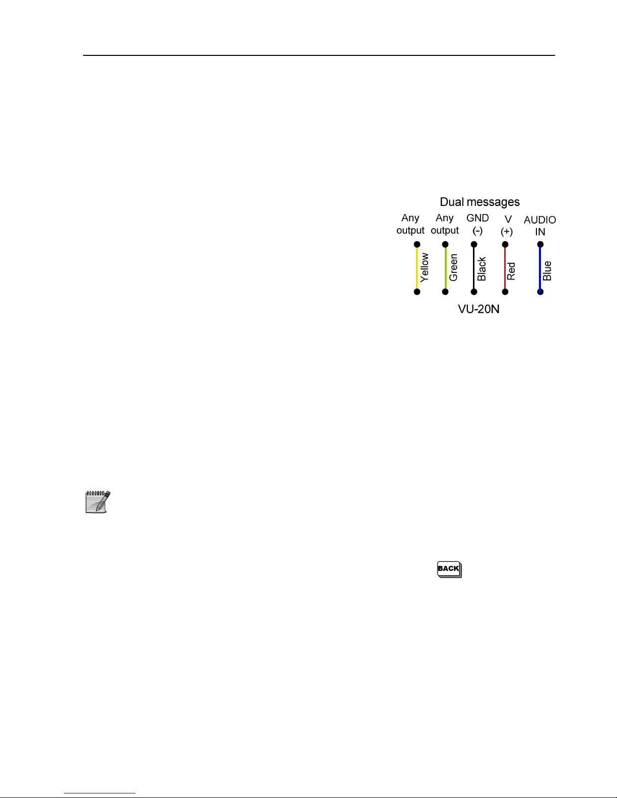
Using VU-20N in HUNTER-PRO series for dual messages can be done only through
partitioning, i.e., each voice message is sent from a zone and an output allocated to a
different partition. When an alarm is triggered in a zone allocated to partition A,
‘Message 1’ is played, and when an alarm is triggered in a zone allocated to partition B,
‘Message 2’ is played.
1. Navigate to a desired output and link it to the
‘Audio control’ output type (#7)
2. Press ENTR and allocate the output to any partition,
by marking ‘+’ under that partition, and ‘-’ under
all others
3. Press ENTR to Polarity and mark ‘-’ under ‘P’
4. Repeat steps 1-3 with a second output
5. Navigate to ‘Zone responses’ (#2), pick the zone
type/s that will trigger the VU-20N ‘Message 1’ and‘
Message 2’ and mark ‘+’ under ‘M - Activate Audio’.
Make sure that the output trim time of ‘Audio
device’ is the default 60 seconds (#4)
Figure 39. Dual messages
6. For each zone, navigate to Partitions (#2) and allocate the zone to the desired
partition by marking ‘+’ (All others should be marked with ‘-’)
7. Navigate to ‘Communication options’ (#3) and mark ‘+’ under ‘V - Voice unit’
3.15 Battery
The HUNTER-PRO series has a rechargeable 12V battery. The system tests the battery
continuously.
If a test fails, the system displays battery fault and responds as
programmed in the faults responses (activating sirens, dialing the
Monitoring Station, etc.)
3.15.1 Manual Battery and Phone Line Test
To manually test the battery and phone line: Master code . If both tests
are OK, a corresponding message is displayed.
If the battery is low, a “Low Battery” message is displayed and the battery should be
replaced.
Page 39

HUNTER-PRO Series Installation Guide 39
3.16 Mains
Before connecting the power cord to the system, verify that
the cord is disconnected from mains
Connect the transformer to the AC terminals on the PCB and then to mains.
With an Ohm meter, check for continuity between the grounding point on the control
panel, PCB and GND terminal, to the electrical outlet grounding point. The resistance
must be less than 1 Ohm.
1. A current limiting device, such as circuit breaker or
fuse, must be connected in serial with the power cord
2. Electrical Grounding must be connected!
3.17 Initializing the System
Make sure the connections to the system are as described in previous sections.
Connect AC mains power supply.
Connect the backup battery to the fast connection terminals, red wire to (+)
and black wire to (-).
Close the control panel case and verify that the screws do not touch the battery.
If you connect the battery before mains, an AC fault will be
displayed until you connect the AC. The fault will be logged
Keypad Ver. 1.15
Keypad ID:0
When connecting to mains, the keypad will sound a
long beep and display the keypad version & ID screen
Starting
Please wait...
Few seconds afterwards the “Please wait” screen is
displayed
1 JAN 09 00:00
Clock not set
Then, the fault LED flashes, and a message that the
clock is not set is displayed. If faults exist, they will be
displayed one by one.
To turn the buzzer off, press
for 3 seconds. In case a new
fault occur the buzz returns. Only after all faults are resolved, the
red LED ceases to flash and the default display appears
Page 40
40 HUNTER-PRO Series Installation Guide
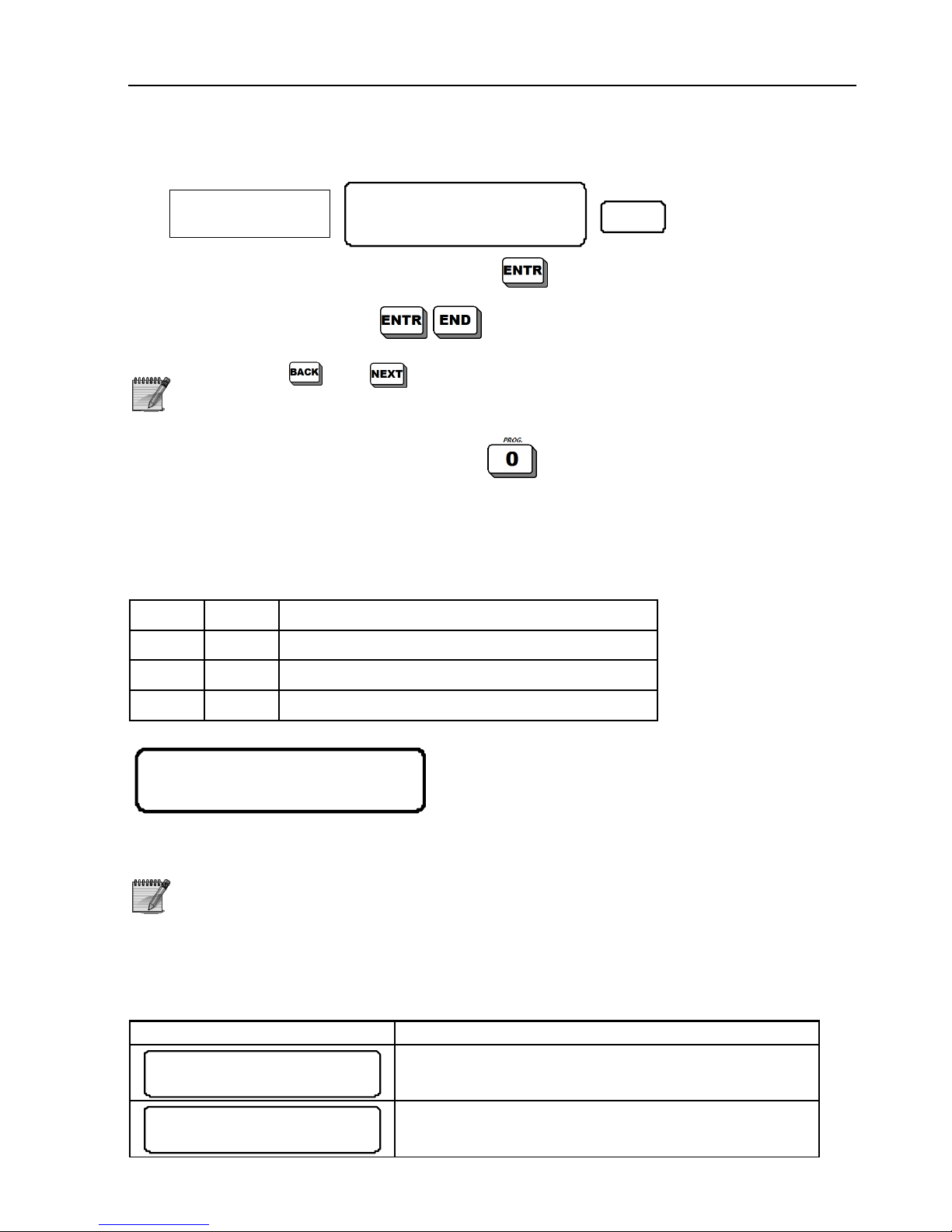
3.17.1 Setting Time & Date
USER MENU
Choose 1,2...
8
Master/User
Code
9
1. Enter the time (HH:MM format) and
2. Enter Date and then
Press
and to move the cursor to the left and right
The user code must be enabled by the installer to set the time
Another way to access the user menu:
Installer Code
3.18 Wireless Faults Display
3.18.1 In PIMA Fast Display
Wireless accessories faults:
Zone Indi. Fault
7 F Wireless zone (Detector’s tamper is open)
14 V Supervision
17 L Low battery
L---------------
------F------V--
1 2 3 4 5 6 7 8 9
17 18 19 20 21 22 23 24 25 26 27 28 29 30 31 32
10 11 12 13 14 15 16
For example: zone #7 (tamper) is open, no
supervision signal is received from zone
(detector) #14, low battery in zone #17.
When the display is set to “Fast Display” and a battery, tamper or
supervision fault occurs, the display is automatically set to “Open
Zones Scan”. When all the faults are resolved the fast display
returns
3.18.2 In Scan Open Zones Display
The following are example wireless receiver faults:
Display Fault
2 JUL 07 13 :10
Wirele ss Un it
Communication fault with the I/O-WN receiver
1 JUL 07 03 :00
W/L Un it Ta mper
I/O-WN’s tamper is opened
Page 41
HUNTER-PRO Series Installation Guide 41
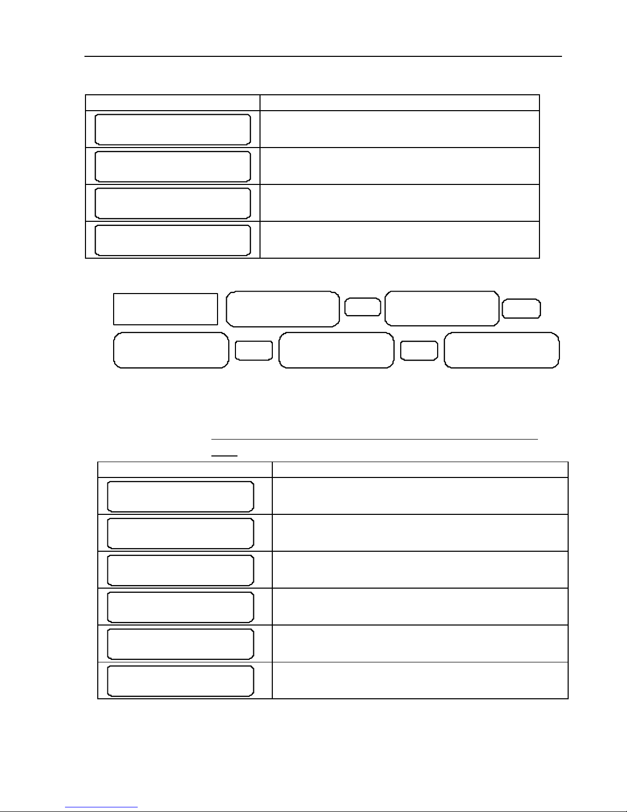
Display Fault
5 JUN 07 14 :20
FL: Zone 14
Tamper open in zone #14
5 JUN 07 14 :25
LB: Zone 19
Low Battery in zone #19
7 OCT 07 16 :32
SV: Zone 35
No supervision signal from zone #35
W/L Re cvr. fail
ENTER/ NEXT/END
This fault appears when trying to program the
I/O-WN although the receiver is not installed
3.18.3 Memory Log of Faults
Show:
All Events-0
9
User Menu
Select 1,2...
MASTER/USER
CODE
2
NEXT
Show:
Defaults Only-1
NEXT
Show:
Zone Alarms-2
NE X T
Show:
Arming/Dis.-3
The memory log has 3 viewing options: 1 - all events, 2- alarms, 3 - arming/disarming.
The top line displays the memory event number (top left) and the time and date in
which the event was registered. The event name is displayed in the bottom line.
3.18.3.1 Examples for faults as displayed in the memory
log:
Memory Log Fault
1) 5 JU N 07 14 :20
W/L R ecv r. f ail
This fault appears when trying to program the
I/O-WN although the receiver is not installed
2) 5 JU N 07 14 :20
Wirel ess Z F aul t
Wireless detector’s tamper switch is open. The
zone name and number are displayed intermittently
3) 5 JU N 07 14 :20
Low B att er y - 15
Low battery in zone #15 (wireless detector)
4) 5 JU N 07 14 :20
Super vis io n - 2 8
Supervision fault in zone #28. The zone’s name
and number are displayed intermittently
5) 5 JU N 07 14 :20
W/L Unit Tamper
I/O-WN receiver tamper fault
6) 5 JU N 07 14 :20
Recei ver J amm .
I/O-WN receiver jamming fault
Page 42
42 HUNTER-PRO Series Installation Guide
CH. 4. PROGRAMMING BASICS
The HUNTER-PRO series is supplied with factory default parameters. In most
installations you will have none or few parameters to program, except for user-specific
parameters, such as telephone numbers, zone names etc.
There are 3 ways to program the HUNTER-PRO series:
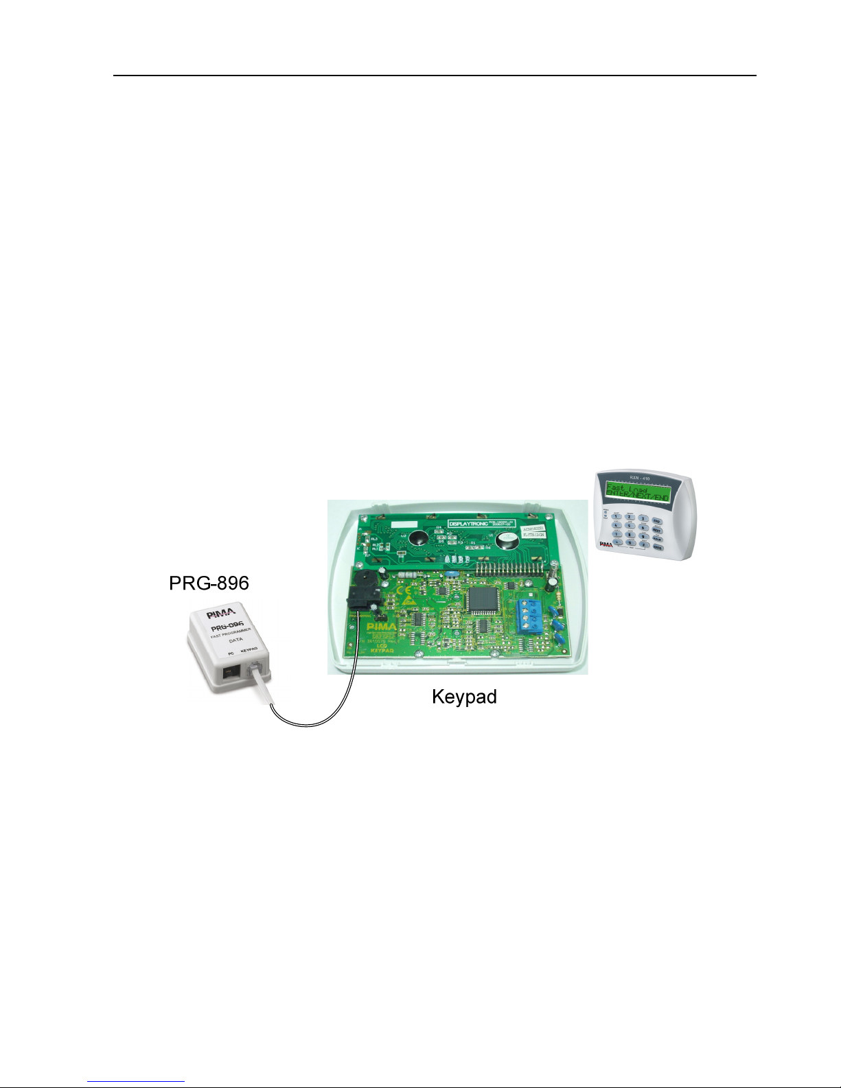
1. Locally with the PIMA Fast Programmer PRG–896. The PRG-896 can have 4/7
different presets. It connects to any LCD keypad.
2. Locally or remotely (via telephone or GSM DATA channel) using COMAX
3. Using the LCD keypad
4.1.1 Fast Programming with PRG-896
PRG-896 is based on ROM chip. It holds parameters that have been uploaded with
COMAX and then downloaded to a system at a site. PRG-896 can only be programmed
with an RXN LCD Keypads. It connects to RJ-11 connector on the keypad PCB. See the
fast programming procedures on section 5.10.3.
Figure 40. Connecting PRG-896 to the LCD Keypad
Page 43
HUNTER-PRO Series Installation Guide 43
4.1.2 Local Programming with COMAX
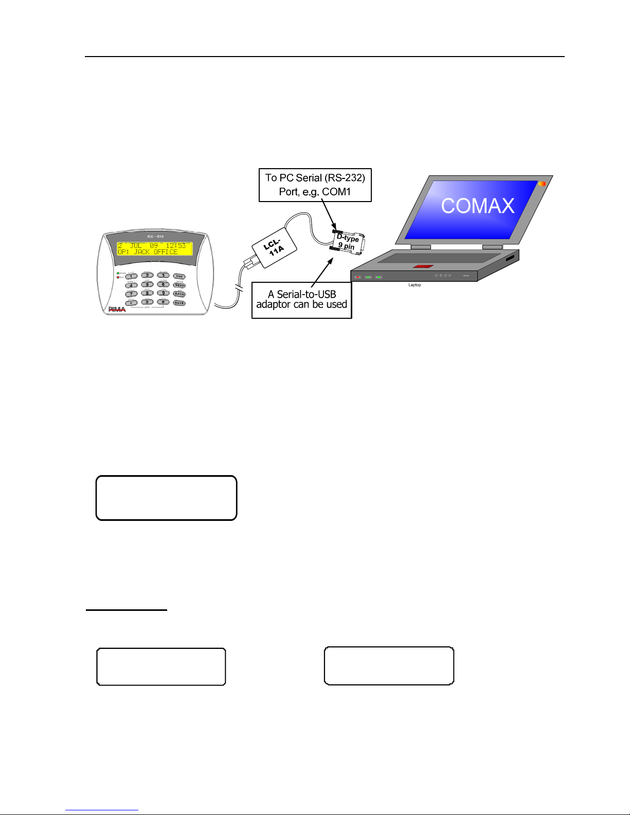
COMAX gives a quick and easy way to upload sets of parameters in the service station
and download them later on at a customer site. Connecting the PC with the COMAX to
the control panel is done using LCL-11A adaptor.
Figure 41. Connecting Keypad to Control Panel and PC with COMAX
4.1.3 Remote Programming with COMAX
The HUNTER-PRO series can be programmed and controlled remotely from any PC,
using PIMA’s COMAX software (with PIMA PSTN modem). Please refer to the COMAX
user guide for detailed information.
4.1.4 Programming with a Keypad
The HUNTER-PRO series has two basic menus: User menu, made of single-press key
commands (the commands are printed above the keypad’s keys), and Installer menu.
SRK12123HTBL
+---_++++---
Example for a zone status
bar
This is a parameters set display.
(+): The parameter is enabled.
(-): The parameter is disabled.
_ : The current programmed parameter
When the flashing sign _ reaches a letter, the display changes for 3 seconds and
shows a brief description of the function.
For example:
Parameters screen
SSAL
----
Parameter’s description automatically appears for
few seconds when curser moved upon parameter
Activate Siren
----
Page 44
44 HUNTER-PRO Series Installation Guide
4.1.5 Navigating through the menu
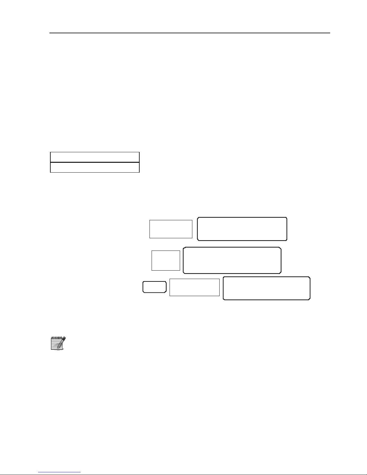
[NEXT] / [BACK]: Backward/Forward keys. Press these keys to navigate between
screens/ options/parameters
[ENTR]: Selection/Conformation key
[END]: Exit/End key: Return to the previous screen without saving
[#]: Reset/Erase/Change status key (“-” to “+” and vice-versa)
4.2 Default Codes
The system default codes are:
Master Code 5555
Technician Code 1234
4.3 User Menu
There are 3 ways to enter the user menu, where parameters like date & time, dialer
numbers and codes are programmed:
1. Using Master code:
User Menu
Choose 1,2..
MASTE R
COD E
9
2. Using enabled (see
notes below) User
code:
User Menu
Choose 1, 2..
US ER
CODE
9
3. Using Technician
code (see notes
below)
TECHNICIAN
COD E
0
9
User Menu
Cho ose 1,2 ..
1. Only enabled user code can access the user menu. To enable it,
mark “+” under “M” in “General Parameters” menu (see section
5.7). As a result, actions such as arming and disarming cannot
be activated directly, but by entering the user code first and
then pressing the desired key.
2. User Code has no authorization to change Master Code.
3. When accessing the user menu from within the technician menu,
changing codes is disabled.
Page 45
HUNTER-PRO Series Installation Guide 45
4.4 Technician Menu
To enter Technician Menu:
MASTER CODE
NEXT
User M enu
Choo se 1, 2. .
TECHNICIAN CODE
Techn ic ian M en u
Choos e 1, 2..
-OR-
TECHNICIAN CODE
Tech ni c ian Men u
Choo se 1, 2. .
4.5 Express Programming Menu
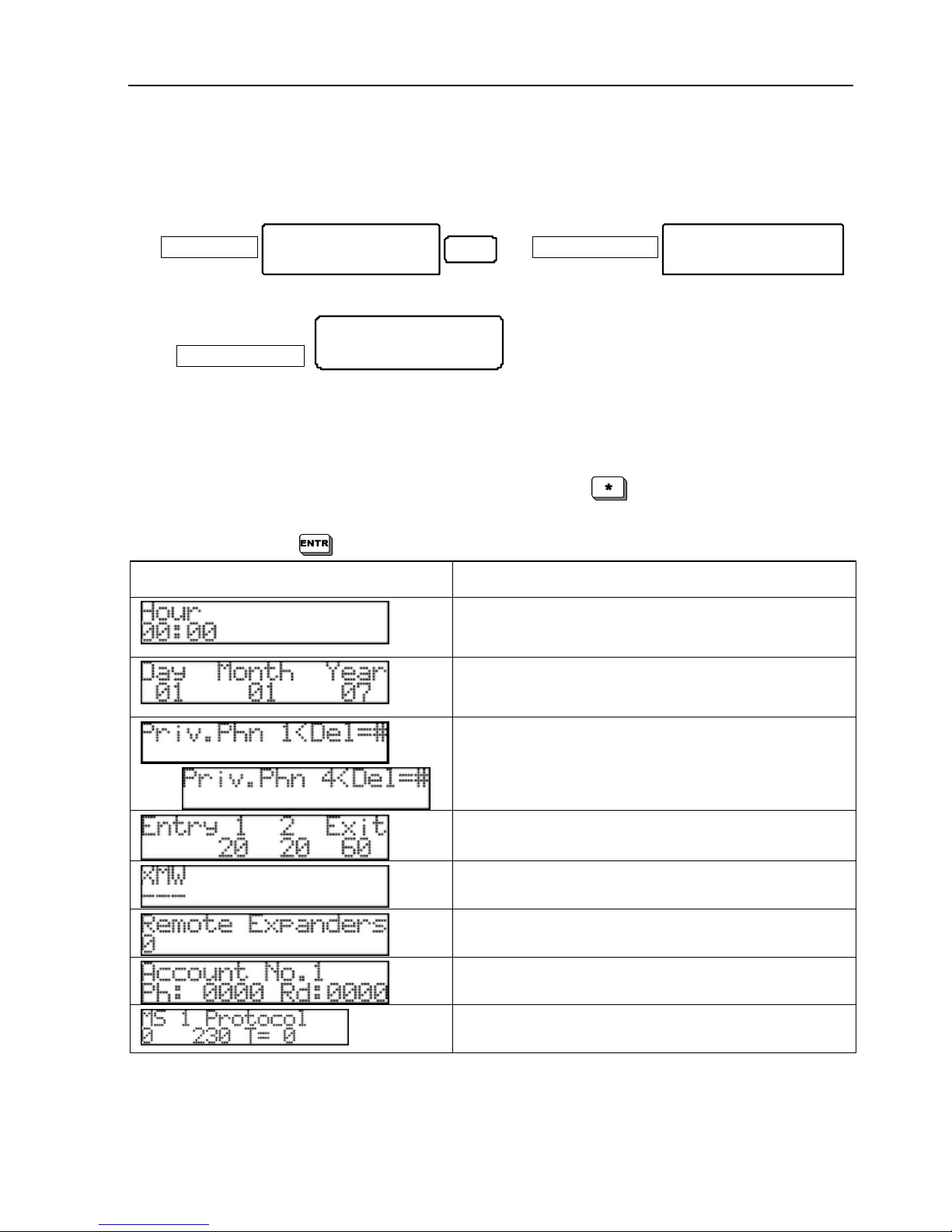
To make programming as easy and quick as possible, the HUNTER-PRO SERIES has a
special menu, made of a sequence of screens with all the necessary parameters to
initialize the system. This menu is accessed by pressing
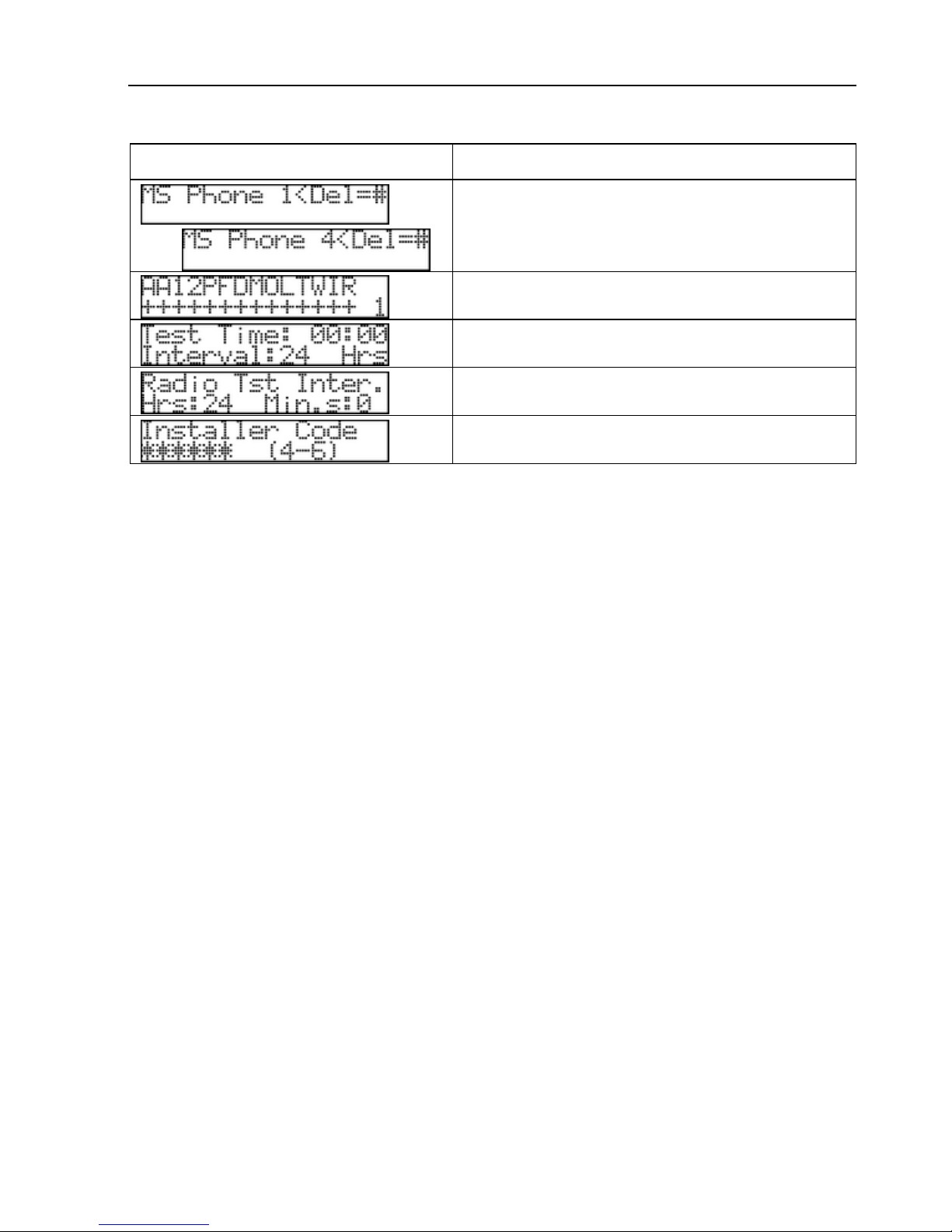
in technician menu.
Following is a table with the express programming screens and their details
consecutively. Press
to save and continue to the next parameter.
Sub-menu Details
Set the time
Set the date
…..
Set the 4 private dialer numbers. Use the
asterisk key for ‘+’, ‘*‘, ‘#’, ‘P’ (one second
pause)
Set the entry/exit delay
Set the expanders - local and wireless
Set the number of remote expanders
Set account #1 phone and radio codes
Set monitoring station #1 protocol
Page 46
46 HUNTER-PRO Series Installation Guide
Sub-menu Details
…..
Set the 4 phone numbers of the monitoring
station #1. Use the asterisk key for ‘+’, ‘*‘,
‘#’, ‘P’ (one second pause)
Set monitoring station #1 reports
Set the monitoring station #1 test time and
interval
Set monitoring station #1 radio test interval
Set the Installer code (4-6 digits)
[ENTR] to save
Page 47

HUNTER-PRO Series Installation Guide 47
CH. 5. PROGRAMMING THE SYSTEM
5.1 The Technician Menu
5.1.1 The Keypad Keys Functions
The Hunter-Pro series technician menu is made of 11 sub-menus, all accessed and
programmed with the LCD keypad keys. The keys and sub-menus are:
Key Functions Page
[1] System Installation: Expanders, Keypads Etc. 48
[2] Zones: Types, Responses, Names, Partitions Etc. 50
[3] Communication: MS1 Options, Subscriber Numbers,
Communication Options, Radio Report Codes Etc.
54
[4] Timers: Entry/Exit Delay, Outputs Times, Reports
Delays, Soak Test Days Etc.
66
[5] General Parameters 69
[6] System Responses: Mains Fault, Battery Fault Etc. 70
[7] Outputs Configurations 71
[8] Full Programming (Reset), Local And Fast Download 75
[9] Installer Code Change 76
[*] Fast Programming 76
[0] Tests 76
5.1.2 Navigating the Menu
Navigating the menu is easy: go to the next level or Save by pressing [ENTER], go
forward and backward by pressing [NEXT] and [BACK], exit without saving or go one
level up by pressing [END].
5.2 Enhanced Communication Menu
The HUNTER-PRO 832/896/8144 has an enhanced communication menu with various
parameters. By default, this menu is not visible, because most installations do not
require changing the defaults for these parameters, which necessitates knowledge in
communication networks to set them.
To make the enhanced menu visible, either mark “+” under ‘P’ in the first “General
Parameters” screen (see section 5.7.1) or press [*] for 3 seconds in the first screen of
the Communication menu (key #3).
Page 48
48 HUNTER-PRO Series Installation Guide
5.3 Key #1: System Installation
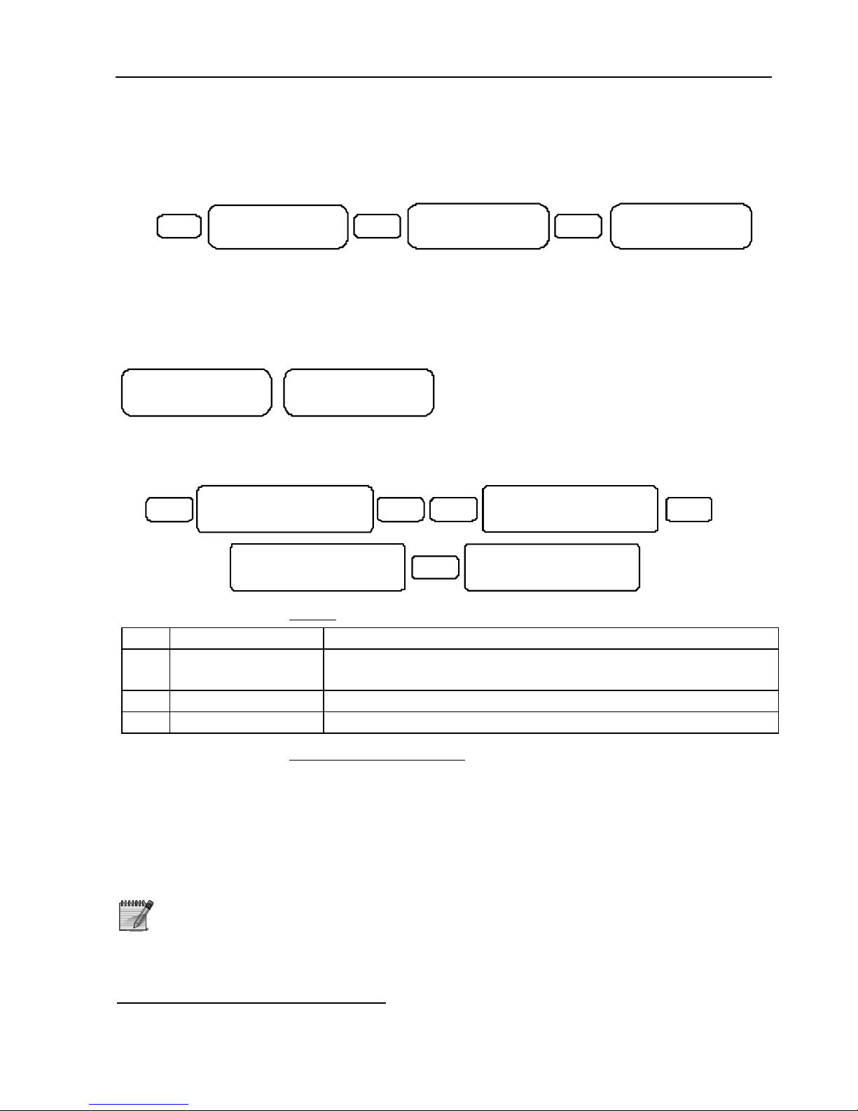
5.3.1 Service Provider and End of Service Date
ENT R
1
Service Pr ovider
ENTER/NEXT /END
9
Sys Installa tion
ENTER/NEXT/E ND
ENTR
Serv ice Provider
PIMA El. Systems
Enter the system’s service provider’s details, such as name and telephone number.
To show this screen at any time, press [NEXT] for 2 seconds when the system is not
armed.
Press [ENTR] and enter the date in which the service ends. In that date, the following
2 messages appear onscreen
*
intermittently:
1 4 M AR 0 8 12 :0 0
C all S er vic e
14 MA R 08 1 2: 00
Se rvi ce P rov id er
..
.
. The messages cease to appear the next
time the system is armed or when technician code is entered.
5.3.2 Expanders
ENTR
1
Expanders
ENTER/NEXT/END
ENTRNE XT
Sys Installation
EN T ER /N E XT /E ND
XMW
---
ENTR
Remote Expanders
0
5.3.2.1 Local
Par. Name Marking “+” means
X Local Expander Local expander EXP-PRO UNIV with 8 additional zones is
installed
M Zone Doubling This feature is enabled
W Wireless Expander I/O-WN wireless receiver is installed
5.3.2.2 Remote Expanders
Set the number of the installed remote expanders (with no EXP-PRO UNIV installed).
The no. of remote expanders varies according to the system:
In Hunter-Pro 832: 3 max.
In Hunter-Pro 896: 11 max.
In Hunter-Pro 8144: 16 max.
Entering a number exceeding the max. will result in an error
*
This message appears only if the service provider and the end of service date
were set
Page 49
HUNTER-PRO Series Installation Guide 49
5.3.3 Setting the Wireless Expander
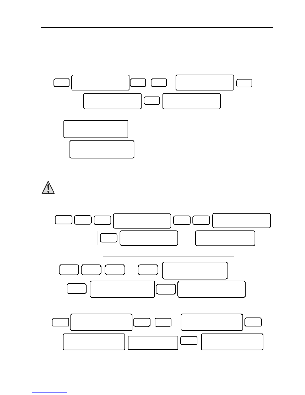
To set the wireless expander parameters, first mark “+” under “W” in the expanders
menu (see previous section).
ENTR
1
Wireless Setup
ENTER/NEXT/END
ENTR
NE X T
Sys Installation
ENTER/NEXT/END
X2
9
Add Zone?
ENTER/NEXT/END
ENTR
Add Zone? 9
ENTER/NEXT/END
The first available zone appears (zone #9 is first, if no expander is installed). Press
[ENTR]
Add Zone?
Activate Device
. Trigger the wireless device and wait for confirmation
message:
Device added
Press END
.
The number of wireless zones & accessories varies according to the system. See the
table in section 1.1
The wireless zones are numbered only after all other zones,
including hardwired expanders
5.3.3.1 Deleting a Wireless Zone
ENTR
1
Wireless Setup
ENTER/NEXT/END
ENTR
NEXT
9
NEXT
Device Deleted
Press END
Delete Zone? 9
Please Wait...
….
Enter a zone
number
ENTR
Delete Zone?
Please Wait...
5.3.3.2 Supervision Interval for Wireless Zones
Add Zone?
ENTER/NEXT/END
Superv is i on:
ENTER/ NE X T/END
Supervision:
Hrs:1 2 Min. s: 0
ENTR1 ENT RNEXT
X2
9
ENTRBACK
5.3.4 Keypads
ENT R
1
K eyp ad s S et up
E NTE R/ NEX T/ END
ENTRNE XT
X3
Keyp ad s Set up
0
S ys I nst al lat io n
E NTE R/ NEX T/ END
ENT R
Enter the number o f
installed keypads
Part. F or RK D
+++++ ++ +++ +++++ +
9
Set the number of monitored keypads (8 max.). Giving a different ID (other then zero,
which indicates a non-monitored keypad) to each will indicate the system to supervise
them, i.e. monitor their tampers. The IDs should be given consecutively from #1.
Page 50
50 HUNTER-PRO Series Installation Guide
If monitoring the keypads is not required, the number of keypads
should be set to zero
5.3.5 Keypad Partitions
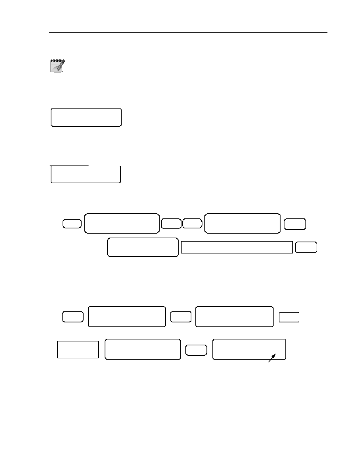
In systems that use partitions, each keypad can control one or more partitions (and
have no control on the others).
Part. For RKD 1
++++++++++++++++
Mark ‘+’ under the partitions that this keypad will control (In
the example, keypad #1 controls all partitions). To set a different keypad, enter a
keypad ID or scroll up/down using [NEXT] and [BACK]. Press [ENTR] to save and
proceed to the next keypad.
For example
, if keypad #2 should only control partition #2 through #4:
Part. For RKD 2
-+++------------
5.3.6 I/O-R Expander Settings
Set the number of I/O-R relay expanders that are connected to the system.
ENTR1
I O-R Exp. Set tin g
E NTE R/N EXT /END
ENTR
BACK
Sys Inst all ati on
E NTE R/N EXT /EN D
Ente r the numb er of ins tal l ed I/O- R exp and er s
I O-R Exp. Set tin g
0
EN TR
5.4 Key #2: Zone Programming
Configure the system’s zones: line, hardwired and expanders.
5.4.1 Zone Types
2
EN TR
Zone Configur.
ENT ER / NE X T /EN D
ENTR
Zones
ENTER/NEXT/END
ENTR
Burglary
Zone 1 1
B OFH HID TEP DESS
- --+ ++- --- -+++ 1
Zone characteristicsZone type
Zo ne na me
Programmed zone
Zo ne nu mber
Enter a z on e
number
These are the HUNTER-PRO series zone types: B
URGLARY, PANIC, FIRE, DURESS/HOLD-UP,
MEDICAL, ANTI-MASK, SPECIAL BURGLARY 1, SPECIAL BURGLARY 2, SILENT PANIC, SPECIAL FIRE.
Enter a number (or scroll with [*]) to pick a zone. Press [NEXT] to choose a different
zone type.
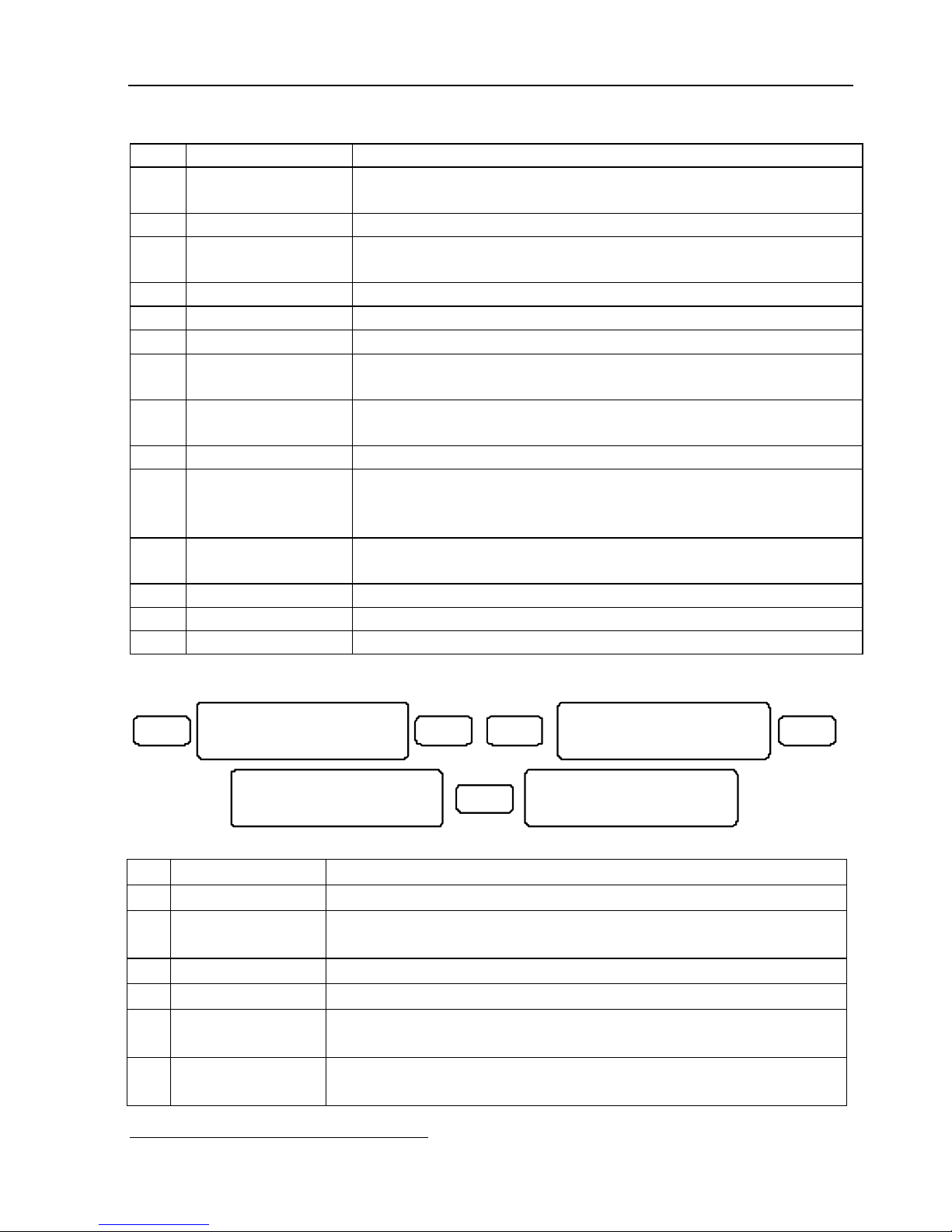
The next table describes the zone characteristics:
Page 51
HUNTER-PRO Series Installation Guide 51
Par. Full Name Enabling (marking “+”) this parameter means
B Bypassed
Permanently
The zone is permanently bypassed
0 Normally Open The zone is set as N.O. zone
F 24 Hour Zone The zone is armed around the clock, regardless of the
system arming state
H Active in ‘Home 1’ The zone is armed in ‘Home 1’ mode
H Active in ‘Home 2’ The zone is armed in ‘Home 2’ mode
I Entry Delay Exit/Entry delayed zone
D Zone Follower This zone will not trigger the alarm if opened during the
Entry/Exit delay
T Second Delay
Time
Setting the Exit/Entry delay time to the second period
(refer to section 5.6)
E EOL Resistors The zone is protected by EOL circuit
P Conditioned Zone The zone triggers the alarm only if other conditioned zone
is violated within the “Cond. Zone Time” (refer to
section 5.6.1)
D Double Knock The zone triggers the alarm only if 2 pulses occur within a
preset period of time (refer to section 5.6.7)
E User Bypass Users can set the zone to be bypassed (temporarily)
S Not in use -
S Not in use -
5.4.2 Zone Responses
2 EN T R ENTRNE X T
Zones
ENTER/NEXT/END
Zo ne Response
EN TER/NEXT/END
Burglary
ENTER/NEXT/END
ENTR
SS LTBM
++ ----
The 6 parameters defining the zone responses are:
Par. Description Enabling (marking “+”) this parameter means…
S Activate Siren Alarms from this zone will trigger the sirens
S Ext. SRN in OFF Alarms from this zone will trigger the external siren even
when the system is disarmed (OFF)
L No Daytime MS No report is sent to the MS when the system is disarmed
T Dif. Siren Tone Different siren tone (not applicable using a DC siren)
B Automatic Bypass False alarm prevention feature: The zone will automatically
become bypassed if 3 alarms occur in it consecutively
M Activate Audio Alarms from this zone will activate the audio device*
(VU-20N or MIC-200)
*
Together with enabling “V” in Communication menu (section 5.5.4), for VU-20N only
Page 52
52 HUNTER-PRO Series Installation Guide
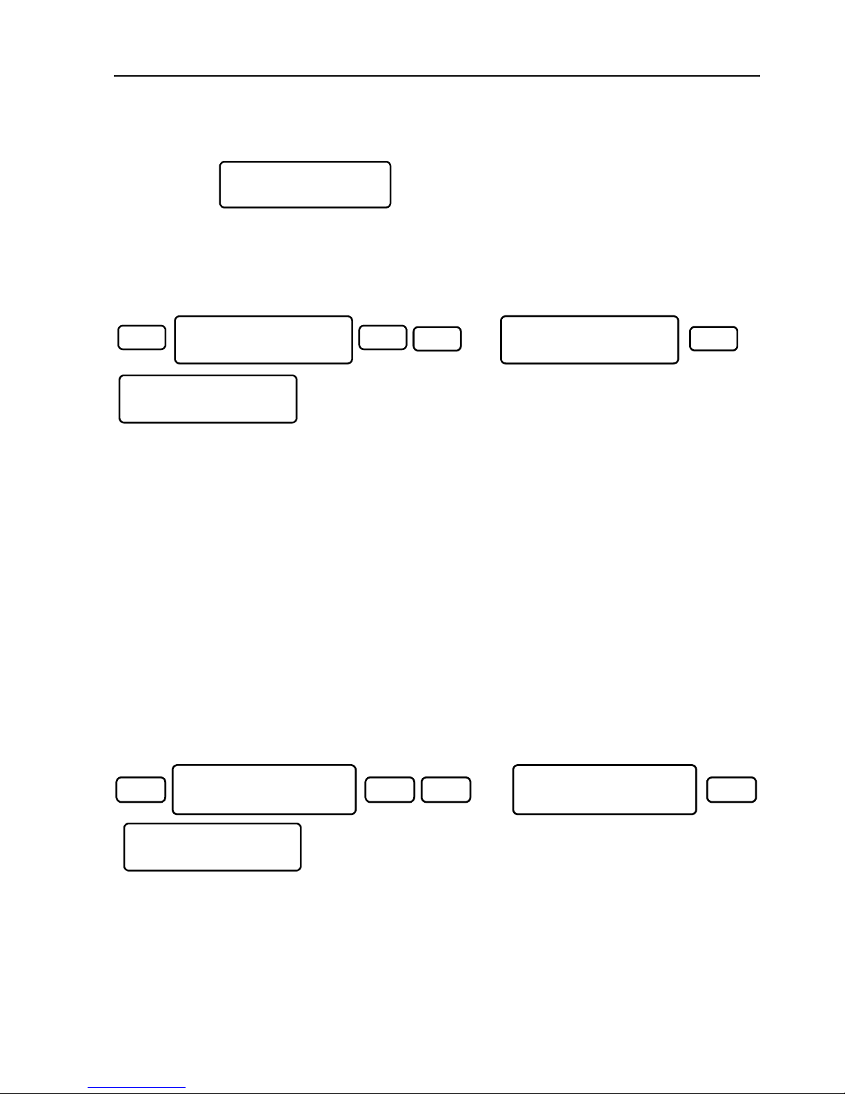
5.4.3 Zone Sensitivity
Press [ENTR]
Sensitiv.(X50mS)
8
Set the zones’ sensitivity in milliseconds.
Sensitivity is the time a zone is violated before it triggers the alarm. The number
entered is multiplied by 50. In the screen above, entering 8 means a sensitivity of 8
times 50, that is 400 ms.
5.4.4 Zone Name
2
ENTR
ENTR
NEXT
Zones
ENTER/NEXT/END
Zone Name
ENTER/NEXT/END
Zone Number: 1
X2
Set the zones’ name. A name can have up to 13 characters. The keypad keys are used
for entering characters, similar to entering text in a cellular phone. See section 1.4
For example, to enter the words “REAR DOOR”:
1. Press [7] 3 times=R
2. Press [3] twice=E
3. Press [2] once=A
4. Press [7] 3 times=R
5. Press [0] once=Space
6. Press [3] once=D
7. Press [6] 3 times=O
8. Press [6] 3 times=O
9. Press [7] 3 times=R
5.4.5 Setting Partitions
2
ENTR ENTRNEXT
x3
Zones
ENTER/NEXT/END
Partitioning
ENTER/NEXT/END
Set the partitions to which the zones are allocated.
Setting the partitions along with setting the keypads’
partitions determines the nature of the system (i.e. Split
System/ Partitioned System).
Marking “+” allocates a zone to a corresponding partition.
Part. For Zone1
+---_-----------
Drawing 6 - Allocating
zones to a partition
For more details on partitions, refer to CH. 2.
Page 53
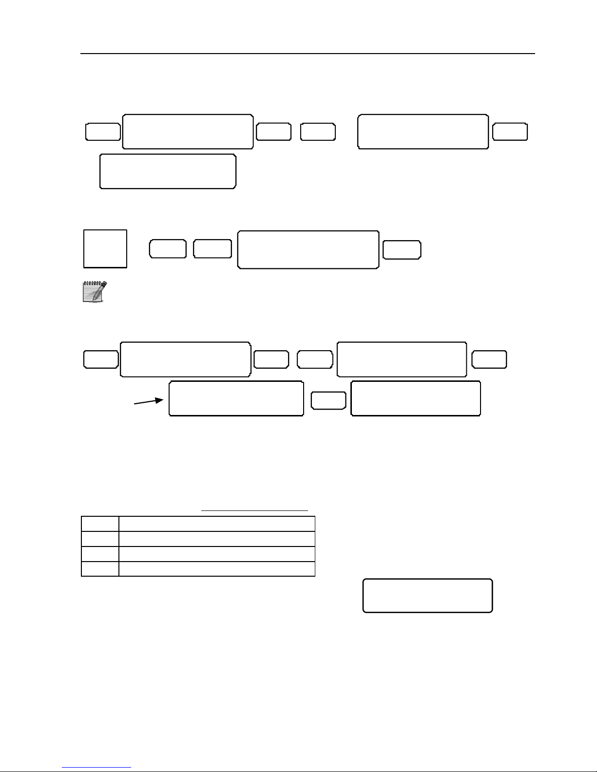
HUNTER-PRO Series Installation Guide 53
5.4.6 Partition Name
2 ENTR ENTRNE X T
x4
Zones
ENTER/NEXT/END
Partition Name
ENTER/NEXT/END
Partition1 Name
Partition 1
The partition’s name will appear on every of its allocated keypad. To enable the
displaying of partitions:
5 ENT R
Display Type:
Show Part Name
BACK
Ent er
Master
Code
Partition names can only be displayed in partitioned keypads
5.4.7 Copy a Zone
2
EN T R ENTRBACK
Zones
ENTER/NEXT/END
Copy Zone
ENTER/NEXT/END
Source Zone: 7
Target: 9 To 32
Ex ample
TCP
+++
ENTR
Copy zone characteristics into other zones is a very useful installation feature, in which
some or all characteristics of one zone can be copied to other zone/s. Once
programming of a single “source” zone is done, copying it onto as many as all other
zones is easy and quickly: Choose one or more ‘target’ zones, define what to copy (see
the next sub-section) and press [ENTR].
5.4.7.1 Copying Options
Par. Marking “+” means…
T Copy the zone type
C Copy the zone characteristics
P Copy the zone allocated partitions
When copying is done the next message is displayed:
Finish Coping!
Press END
Page 54
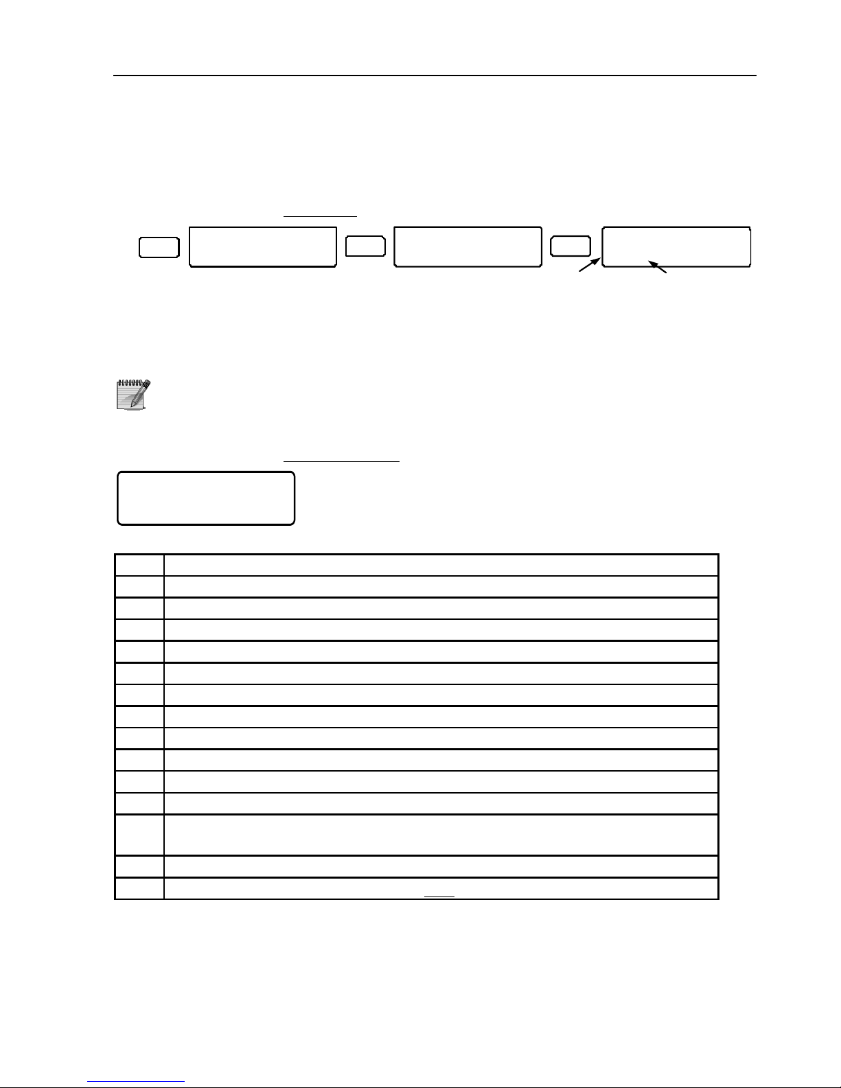
54 HUNTER-PRO Series Installation Guide
5.5 Key #3: Communication Parameters
5.5.1 Monitoring Station #1 Options
5.5.1.1 Protocol
3
EN TR ENTR
Communication
ENTER/NEXT/END
MS 1 Options
ENTER/NEXT/END
MS 1 P ro to c ol
0 230 T= 0
AB
Set MS1 PSTN protocol and radio station no. ‘A’ & ‘B’ (above) determine the PSTN
protocol (see the matching columns in the codes table, section 7.4) and ‘T’ determines
the radio station number (which is determined by the MS).
1. MS 1 is programmed to use ContactID by default
2. If no Radio receiver is installed, do not change the default T=0
value
5.5.1.2 MS1 Reports
AA12PFDMOLTWIR
+++++++++++-++1
Set the events that will be reported to MS1:
Par. Alarm/Event
A All alarms
A Anti-Mask
1 Special Burglary 1
2 Special Burglary 2
P Panic
F Fire
D Duress/Hold-up
M Medical
O Remote open/close (by Phone)
L Failures
T Tests
W Remote Test: When the system is armed, in response to 2 telephone
rings and a hang up the system sends a test report to the MS
I Technician code entered
R Zone Open/Close reports are sent only via the radio
To save, press [ENTR]
Page 55
HUNTER-PRO Series Installation Guide 55
5.5.1.3 PSTN Test Time and Interval
Test Time:00:00
Interval:24 Hrs
Set the daily time and interval for sending test events to the MS. If the time is left
00:00, the system will send the tests only according to the interval.
For example, if the test time is set to 23:00 (11 PM) and the interval to 3 Hrs, then test
reports will be sent every 3 hours and
everyday at 23:00. If the time is 00:00 and the
interval is set to 168 (hours), then the reports will be sent every 168 hours (once a
week). Press [ENTR].
Counting starts only when pressing the [ENTR] key
5.5.1.4 Radio Test Interval
Radio Tst. Inter
Hrs:24 Min.s:0
Set the radio test interval. See the previous sub-section for how-to. Press [ENTR].
5.5.1.5 ID Account Addition
If the account number is made of 6 digits, the first 2 are set in this screen. The rest 4
are set according to the next sub-section.
5.5.2 Account Numbers
3
ENTR ENTR
Communication
ENTER/NEXT/END
Account No.
ENTER/NEXT/END
NE XT
Acouont.No 1
Ph:0000 Rd:0000
Acouont.No 16
Ph:0000 Rd:0000
RadioTelephone
Set the PSTN and Radio account numbers. There can only be 16 accounts (one for
each partition), each with a PSTN subscriber no. and radio subscriber no.
If all the accounts are the same, set only one account (open/close
events will be sent without the account number)
If no subscriber no. is entered, no reports will be sent to the MS
In a system with no partitions, reports will send from account #1
only
Page 56
56 HUNTER-PRO Series Installation Guide
5.5.3 The MS Telephone Numbers
ENTR NEXT
ENTR ENTR
Communication
ENTER/NEXT/END
Phone Numbers
ENTER/NEXT/END
MS Pho ne 1< Del = # MS Phone 4<Del=#
X23
….
Set MS1 telephone numbers (4 max.). If the system reports to 2 MSs (double report),
telephones #1 & #2 are allocated to MS1, and #3 & #4 to MS2. Press [ENTR].
When the MS does not answer a call from telephone #1, the
system tries to dial the other numbers. The system performs up to
8 dialing attempts in all
5.5.4 Communication Options
3 ENTR EN TRNEXT
X3
Commun ica tio n
ENTER/ NEX T/E ND
Comm un. Op tio ns
ENTE R/N EXT /EN D
P TLLTA VDRP OSD
+ ---+- --+- +--
Par. Description Setting to ‘+’ means…
P Connected T.Line A telephone line is connected to the system
T No Dia. tone chck The system dials without checking for a dial tone (in case
the system connected via switch-board or the line is not
clear)
L Line Test in ON The system tests the phone line once a minute when it is
armed
L Line Test in OFF The system tests the phone line once a minute when it is
disarmed
T Tone Dial “+” For tone (DTMF)
“-“ For Pulse
A Answer. Machine If answering or fax machine are connected to the phone
line, the system snaps incomin
g
call following a sequence of
two rings, hang-up, 10 seconds pause and a ring
Set the answering machine to pick calls
after more than 2 rings
V Voice Unit VU-20 voice unit is connected to the system
D Download Disable Downloading parameters remotely using COMAX is disabled
(default). To enable it, the user must enter Master code and
press [ENTR] twice (The Comax must dial the system within
2 minutes or it will be reset to ‘+’ [disabled])
R Rem. Disarm
Disab
Remote disarming by the telephone is disabled
Page 57
HUNTER-PRO Series Installation Guide 57
Par. Description Setting to ‘+’ means…
P Pre Alarm Report The system reports when entry delay starts
O Tst Rprt in OFF Test reports are sent when the system is disarmed
S Split Account No. When reporting to 2 MSs (with different account numbers),
account #1 will be reported to MS1 and #2 to MS2.
Assigning account number per partition is disabled.
D Disarm after Al. The system will report a zone open event that occurs
immediately after alarm, even when the open/close
parameter is disabled (in MS1 options menu).
5.5.4.1 Number of Rings
No. of Rings 10
Set the number of rings before the system picks up an incoming call. To manually
answer, enter Master code and press [ENTR] twice. Press [ENTR]
5.5.4.2 ACK Waiting Time
Ack Wait Time:
PSTN:20 GSM:30
Set ACK time (the time in seconds in which the panel waits for MS handshake signal).
If no ACK is received, a communication error is displayed. HUNTER-PRO series allows
different waiting times for PSTN and GSM modules. The max. waiting time for both is
60 sec. Press [ENTR]
5.5.4.3 External Line
External Line
_
Set a dial-up access number (up to 2 digits). Press [ENTR]
5.5.4.4 Number of Transmissions
No. of Trans.: 5
Set the number of the long-range radio re-transmissions. The interval between the
transmissions is 10 seconds. Press [ENTR]
Page 58
58 HUNTER-PRO Series Installation Guide
5.5.4.5 Communication Channels
Set the main communication channel with the MS: PSTN, GSM or IP. If the system
cannot communicate through the main channel, it will try to send reports through the
other two, while continuing to try in the first.
PGN
+--
Par. Channel
P PSTN (default)
G GSM
N IP network (MS1 only)
5.5.5 Report Codes 4X2
5.5.5.1 Zones
Report codes are hexadecimal number (and can therefore be made of the digits “0”
through “9” and the letters “A” to “F”). The system’s default code is FF for all zones. If
the FF codes are not changed, the system uses ContactID
©
protocol (which includes
PAF & NPAF). To change a code, do as follows: subtract 100 from the ContactID event
number and convert the result to hexadecimal number.
For example, to send “High Temperature” event (ContactID event 158): 158 less 100 is
58. converted to Hex. is 3A.
The restore code must match the alarm code
3 ENTR ENTRNEXT
X4
Communication
ENTER/NEXT/END
Report Codes 4X2
ENTER/NEXT/END
Zo ne s
ENTER/NEXT/END
ENTR
Z1: FF Z2: FF
Z3: FF Z4: FF
The PSTN report codes (4x2) menu and the following radio menu have 3 sub-menus:
Zones, Zones’ restore and General Reports.
To set a code: Use [NEXT] and [BACK] to move between zones, [*] to pick letters and
the keypad keys to pick digits, [ENTR] to the move to the next screen.
5.5.5.2 Codes Table
Code Details
Z1 ,Z2 , ... Z96 Alarm from zone #1, #2, etc.
R1 ,R2 , ... R96 Restore code from zones #1, #2, etc. The report is sent at the
end of the siren time or when the system is disarmed
immediately after alarm.
ZFL + RESTR Zone fault in EOL zone + Restore code
BYP Zone Bypassed
TM1, TM2 +
RESTR
TMPR 1 and/or TMPR 2 are violated + Restore Code
Page 59
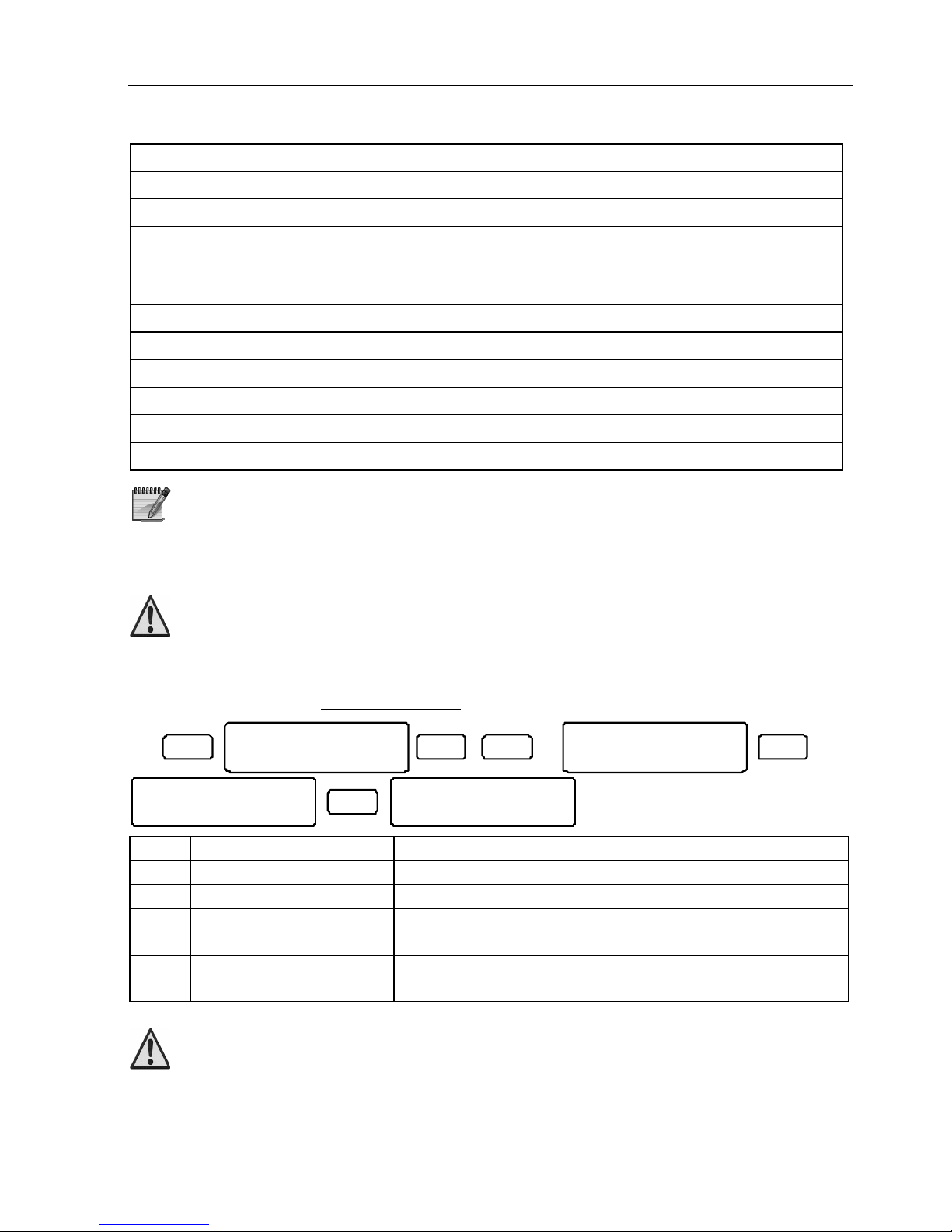
HUNTER-PRO Series Installation Guide 59
Code Details
AC + RESTR Mains voltage (AC) failure + Restore Code
LB + RESTR Low Battery + Restore Code
PF + RESTR Power Failure: Card voltage lower than 9 volts + Restore Code.
Low card voltage indicates AC failure and low battery
PHN + RESTR Telephone Line Failure + Restore Code
PNC Panic code
ICODE Incorrect code entered
FUS + RESTR Fail-Unsafe State: Detectors’ Voltage Fault + Restore Code
ARM System has been armed
DISAR System has been disarmed
TST System has been tested (manually, automatically, or “wake-up”).
The restore code is displayed as “RESTR” to the event’s right
5.5.6 GSM Transmitter
The following menus are available only if the enhanced menu
is enabled (see section 5.2)
Configure the GSM-200 cellular transmitter.
5.5.6.1 GSM Settings
3
ENTR ENTRNEXT
X6
Communicatio n
ENTER/NEXT/E ND
GSM Tr ansmitte r
ENTER/NEXT/END
GSM Set tings
ENTER/NEXT/END
ENTR
GRTY
----
Par. Name Mark “+” to indicate that…
G GSM TX Installed GSM-200 transmitter is installed
R Use Radio ID Account Radio Account IDs will be used for GSM reports
T Auto Test Report Reports for auto-test will be sent via GSM (in
addition to PSTN)
Y GPRS Encryption The information sent via GSM will be encrypted and
sent via GPRS
If there is no radio transmitter connected to the system, ‘T’
(wireless communication) should be set to zero in the
communication format screen (see section 5.5.1.1)
Page 60
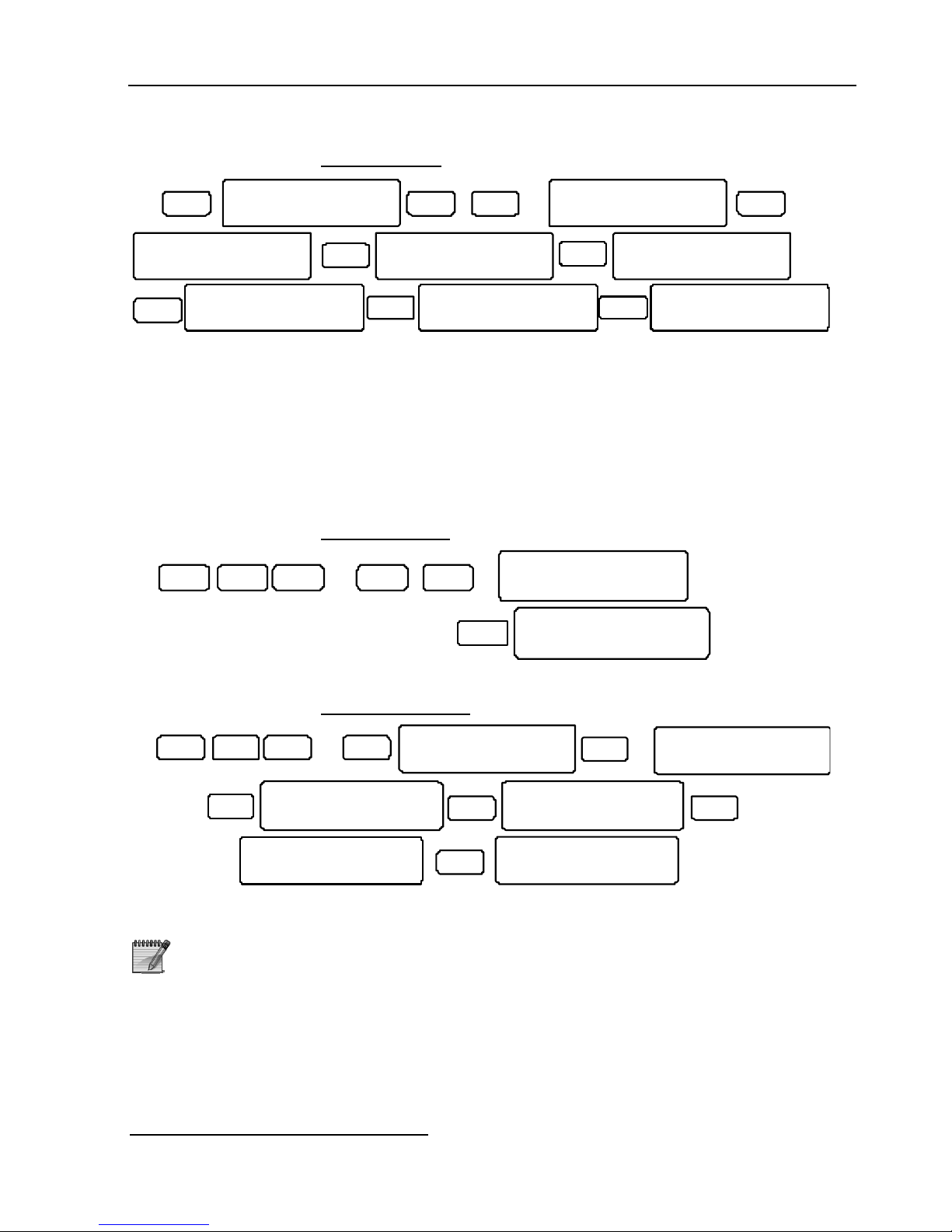
60 HUNTER-PRO Series Installation Guide
5.5.6.2 GSM Modes
3 ENTR ENTRNEXT
X6
Communication
ENTER/NEXT/END
GSM Transmitter
ENTER/NEXT/END
GSM Settings
ENTER/NEXT/END
NEXT
GSM Modes
ENTER/NEXT/END
ENTR
GSM-200 Mode 1
Voice Channel
NE X T
GSM-200 Mode 1
Data Channel
NEXT
GSM-200 Mode 1
GPRS Channel
NE X T
GSM-200 Mode 1
SMS Channel
Set the GSM-200 one of two operation modes: Mode 1 for MS1 and mode 2 for MS2
(double report). Each mode can be set to one of four channels: Voice, Data, GPRS or
SMS
*
. In each screen, press [ENTR] to choose Mode 2.
The Data channel can be used by COMAX. To do so, the GSM-200 SIM card must carry
2 separate phone numbers.
If both MSs use GPRS (Mode 1 & Mode 2), the second mode will be used to report
to MS2.
5.5.6.3 GSM Phones
NEXT
G SM P hon es
E NTER /NEX T/E ND
ENTR
MS Ph one 1<De l=#
X23 ENTR ENT RNEXT
X6
Set MS1 GSM phone numbers 1 to 4.
5.5.6.4 GPRS Settings
GSM Settings
ENTER/NEXT/END
NEXT
GPRS Settings
ENTER/NEXT/END
ENTR
Station 1 IP
0. 0. 0. 0.
X3
ENTR
Station Port
10001 10001
ENTR
Tst intrvl(GPRS)
Min:5 Secnd:0
3
ENTR ENTRNEX T
X6
Station 2 IP
0. 0. 0. 0 .
ENTR
Set the GPRS parameters for the MSs. These include the IP no., port no. and test interval.
To see the GSM-200 version (and the SMS-100, if installed), in the
main screen, press [ENTR] until it is displayed. The display will
show both the transmitter and the system version.
*
GSM-200 and SMS-100 cannot be installed in the same system
Page 61
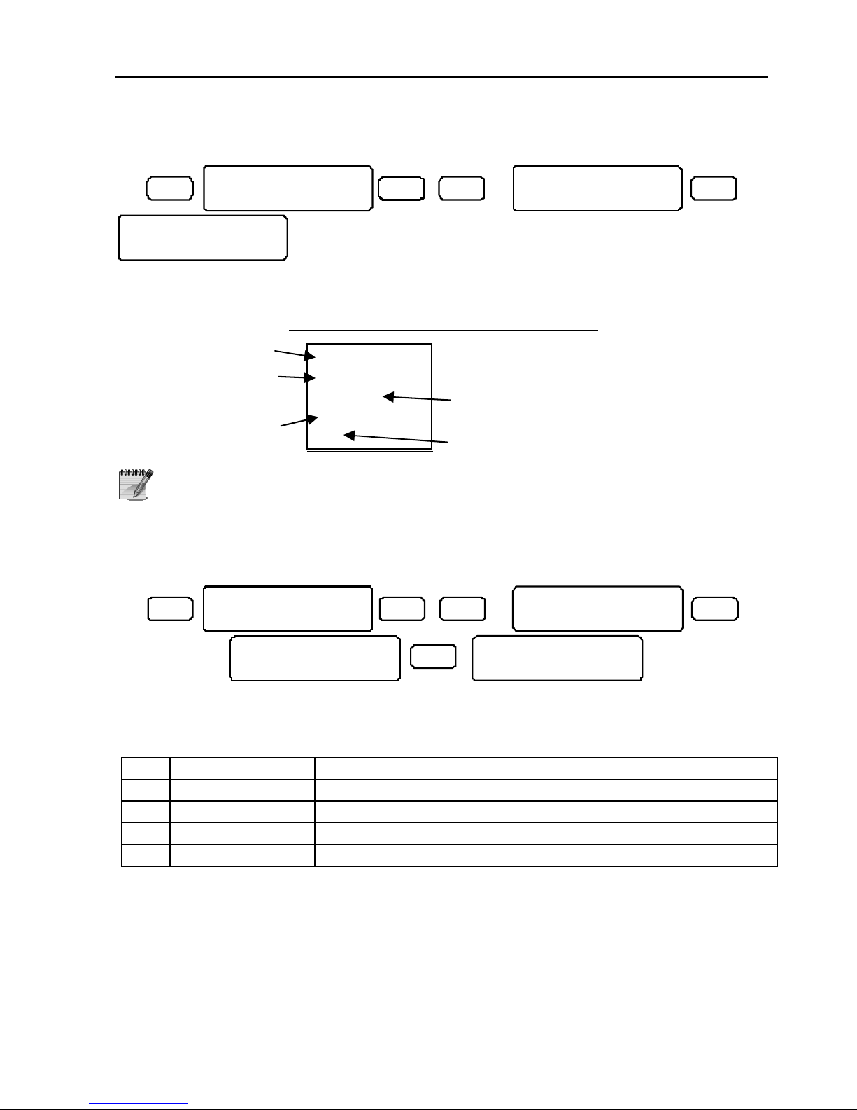
HUNTER-PRO Series Installation Guide 61
5.5.7 SMS Settings
3 ENTR ENTRNEX T
X7
Communic atio n
ENTER/NE XT/E ND
SMS Setti ngs
ENTER/NEX T/EN D
System Na me-S MS
Alarm Sys tem
Set a name to identify the system in SMS reports. A name can be the customer’s name
or any other. “Alarm System” is the default name.
5.5.7.1 A demo cell phone SMS message
System’s name for SMS
Event type and zone no.
Time of alarm/event
Zone name
Date of alarm/event, as
registered in memory log
The text and time for the SMS messages is taken from the
system’s memory log
For further SMS definitions, refer to section 5.5.12.2
5.5.8 Serial Output
3 ENTR ENTRNEXT
X8
Co mmuni cati on
EN TER/N EXT/ END
Serial Ou tput
ENTER/NEX T/EN D
LNLN
____
ENTR
Lcl.Mo n.In terv al
5 Se conds
Set the serial output use, regarding the connection to the MS. The MS can be
connected locally, using RS-232 cable, or remotely, through the net4pro IP interface. It
can use a home automation (“Smart home”) or PIMA proprietary protocol.
Par. Name Marking “+” means the device is…
L Home Automat. 1 MS1 uses Home automation*/Building management protocol
N Network MS MS1 uses PIMA’s proprietary protocol
L Home Automat. 2 MS2 uses Home automation*/Building management protocol
N Network MS MS2 uses PIMA’s proprietary protocol
*
Known also as “Smart home”
Home
Burgl Alarm 2
TV room
11:35
15
Page 62
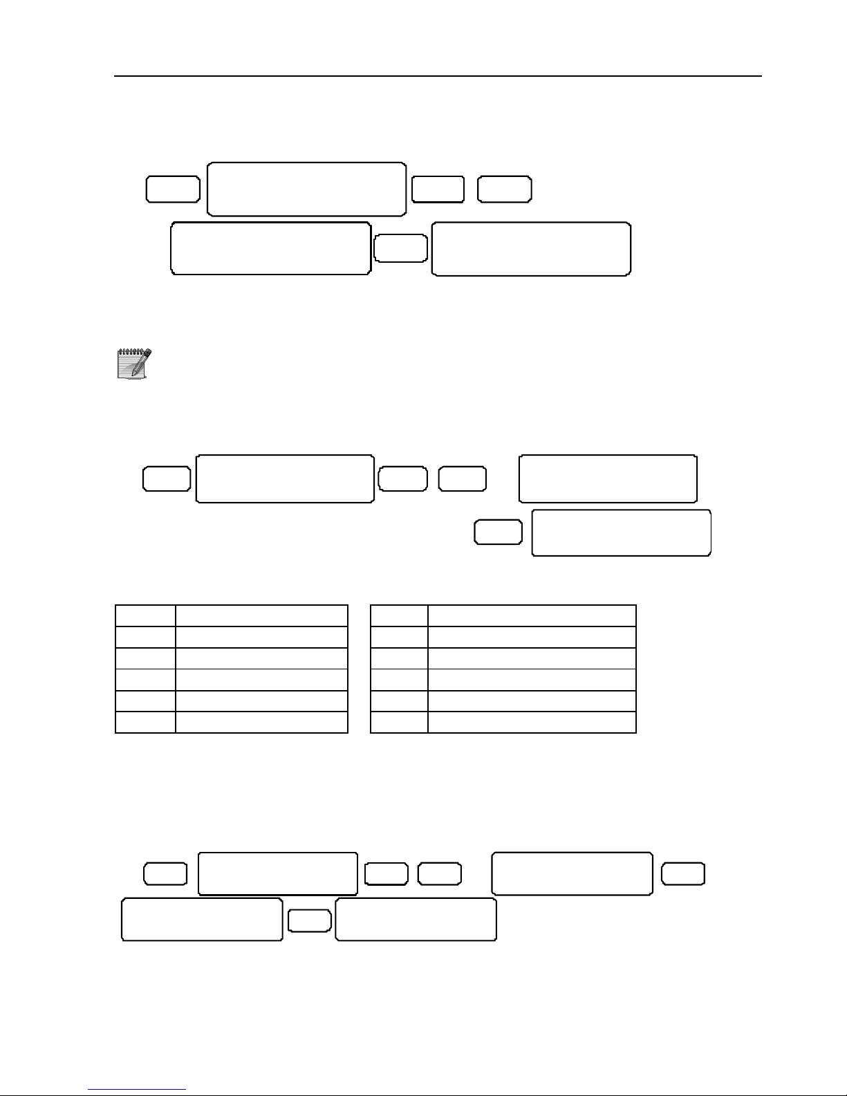
62 HUNTER-PRO Series Installation Guide
5.5.9 Modem Call Back
3
ENTR
ENTR
NE XT
X9
Communic at ion
ENTER/NE XT /EN D
Mode m Ca ll Ba ck
ENTE R/NEX T/END
Call Back1<Del=#
Set the modem callback phone numbers. Up to 3 numbers can be programmed.
If callback telephone #1 is set, in any attempt to contact the
system over the telephone line, the panel will hang up and call the
PC back. This is yet another safety step to protect the system from
unauthorized access
5.5.10 The Private Dialer
3
EN T R
ENTR
NEXT
X10
Communi cation
ENTER/N EXT/END
Priva te Di aler
ENTER /NEXT/END
AA1 2PFDMOL
+++ +++++-+
Set which alarms and events will be reported through the private dialer. Open/Close
events are relevant to SMS only.
Par. Name Par. Name
A Alarms F Fire
A Anti-mask Alarm D Duress
1 Special Burglary 1 M Medical
2 Special Burglary 2 O Open/Close (SMS only)*
P Panic L Failures
* For a user to receive open/close reports by SMS, its settings (in the User menu ->
User codes -> User settings, Parameter ‘O’) must enable it specifically, or only the
system arming/disarming SMS reports will be sent to him.
5.5.11 MS2 Options
3 ENTR ENTRNEXT X11
Communication
ENTER/NEXT/END
MS 2 Opt ions
EN TER/N EXT/E ND
AA 12PF DMOLT WIR
++ ++++ +++++ +++.2
MS 2 Pr otoc ol
0 0
ENTR
Page 63
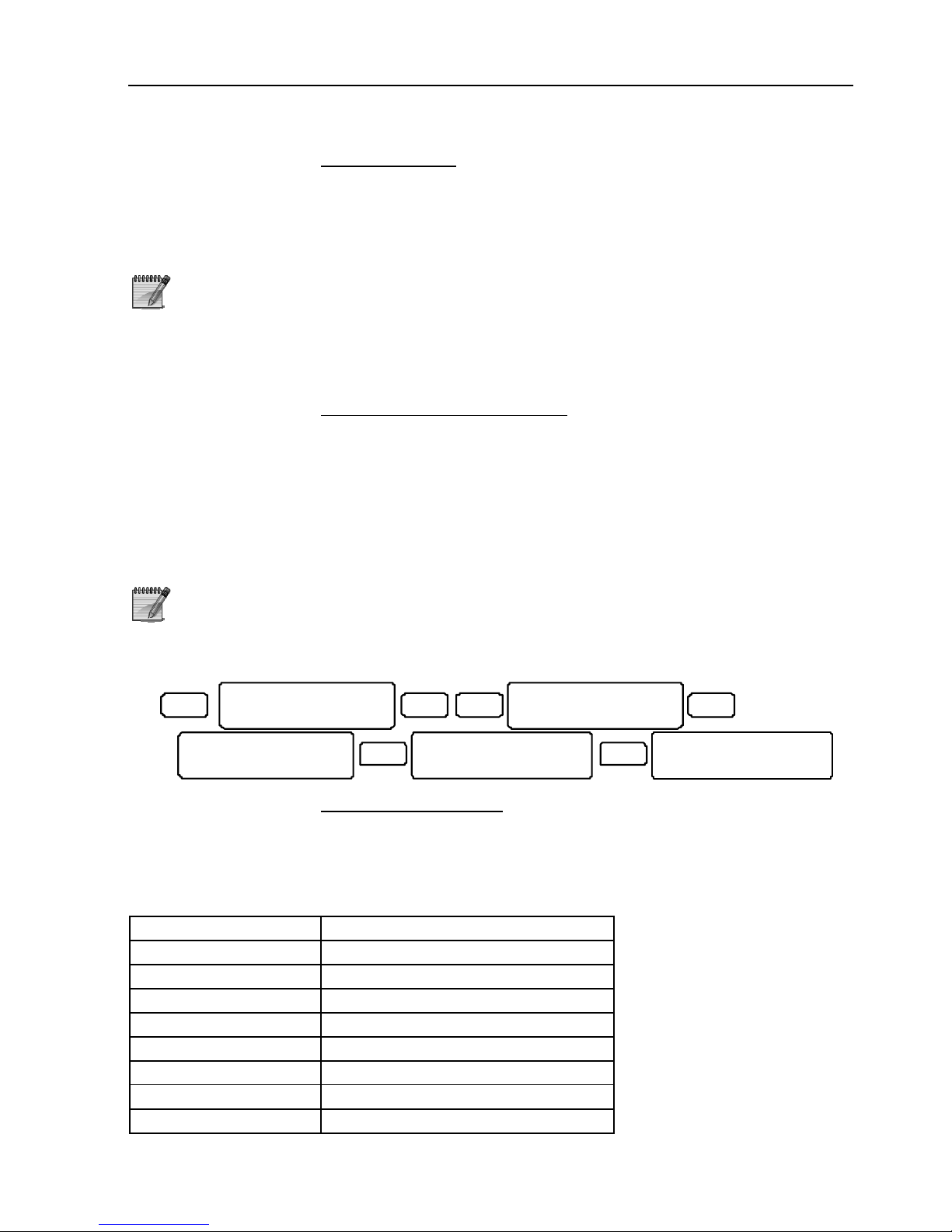
HUNTER-PRO Series Installation Guide 63
5.5.11.1 MS2 Protocol
Set MS2 PSTN protocol. Setting this protocol indicates the system to report to 2
monitoring stations (Double report).
In order to report to 2 monitoring stations with 2 different account
IDs, mark “+” under “S” (Split Subscriber) in “Communication
Options” menu (section 5.5). In this case, Account #1 subscriber
numbers will be sent to MS1 and Account #2 subscriber numbers
to MS2.
To disable the reporting to MS2 set its protocol to (0 0).
5.5.11.2 MS2 Report Parameters
Set which alarm/event will be reported to Monitoring Station 2. All parameters are
similar to those of Monitoring Station 1 as described in section 5.5.1, accept for the
radio (‘R’): Reporting to MS2 via radio is not available.
5.5.12 Advanced Programming
Advanced programming may require professional knowledge in
communication protocols. Beware not to change the default
parameters unless you checked it with the cellular provider first.
To enter Advanced Programming you must first enable it. See how
in section 5.2
3
ENTR ENTRBAC K
Communication
ENTER/NEXT/END
Advanced Prog.
ENTER/NEXT/END
Choose Provider
ENTER/NEXT/END
NEX T
Cell. Providers
ENTER/NEXT/END
ENTR
Cell. Providers1
ENTER/NEXT/END
5.5.12.1 Cellular Providers
Set the information regarding the cellular providers. Up to 5 providers can be
programmed. The system is pre-programmed with some local providers.
The information should be provided by the cellular provider. Press [ENTR]. The next
screens are:
Screen Information to enter
Provider Name 1 Provider 1 name
SMS center phone 1 Provider 1 SMS center phone no.
Provider APN…1 Provider 1 APN no.
Provider APN…1 Continue
User… 1 Username for provider 1
User 1 Continue
Password… 1 Password
Password 1 Continue
To set another provider press [NEXT] in “Cell. Providers1” screen.
Page 64
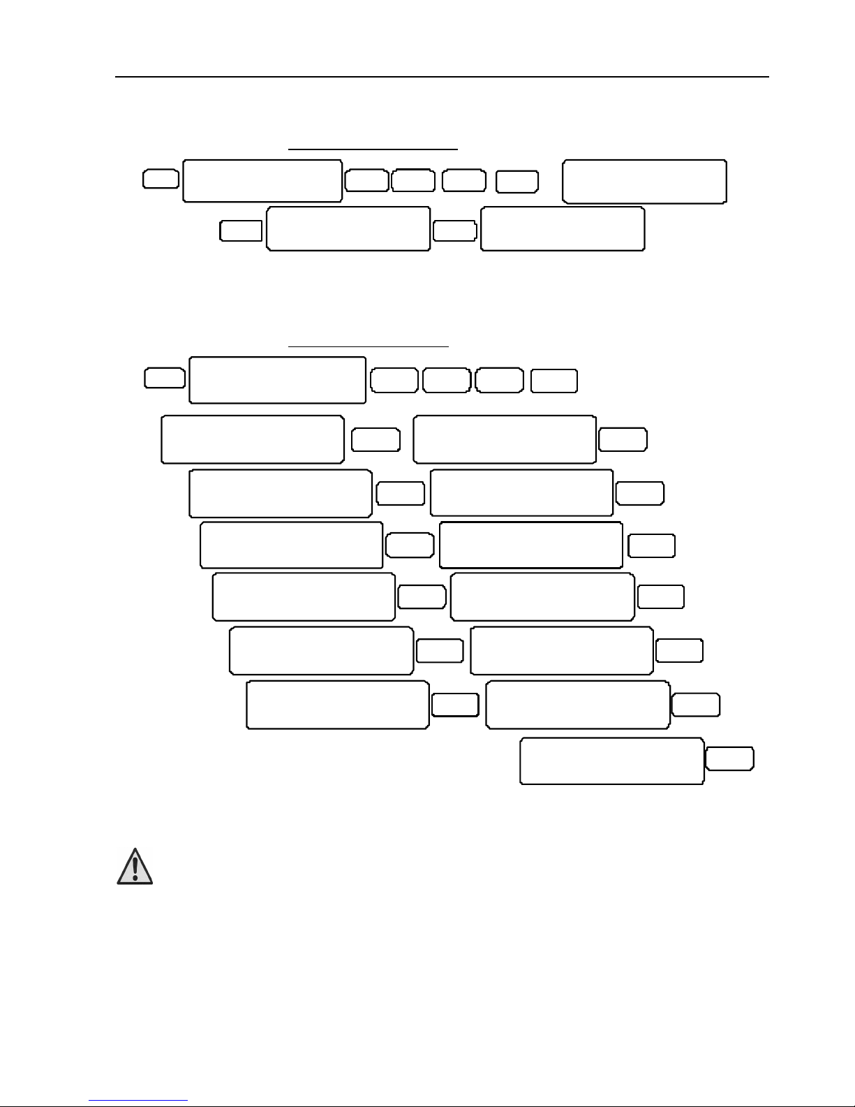
64 HUNTER-PRO Series Installation Guide
5.5.12.2 PSTN SMS Phones
3 EN TR EN TRB ACK
Communication
ENTER/NEXT/END
NE X T
PSTN SMS Phone
ENTER/NEXT/END
X2
ENTR
SMS Center OUT
EN T R
SMS Center IN
Set the details for the SMS-100 PSTN module.
OUT is the PSTN SMS center phone no.
IN is currently not in use
5.5.12.3 Network Settings
3 ENTR ENTRBACK
Communication
ENTER/NEXT/END
BACK
Netw or k S etti ng s
ENTE R/ NE X T/ EN D
EN TR
9
MS1 URL/IP
EN TR
ENTR
MS2 URL/IP
EN TR
MS1P or t M S2 Port
10001 10001
ENTR
ENTR
UploadPort:10001
Web Port: 10001
ENT R
STATIC IP
0 .0 .0 .0
ENTR
SU BN ET MASK:
0 .0 .0 .0
ENTR
DEFA UL T G ATEW AY :
0 .0 .0 .0
ENT R
DNS SERVER
0 .0 .0 . 0
ENTR
Tes t i nt erva l
Min:1 Secnd:0
ENTR
AttemptsTo Fail
10
ENTR
Enter the IP network parameters. As in any IP network, the IP no. can either be static,
or dynamic, using a DHCP (Dynamic Host Configuration Protocol) server.
If you use net4pro-i (P/N 6247001), the URL/IP screen must
be left blank
To use static IP fill in the parameters in the next screens. If you use a DHCP server the
system will ignore the Static IP screen and the 3 following screens.
The URL/IP and Station Port screens are mandatory, both when using static or dynamic
IP. See the next table for further details.
Page 65
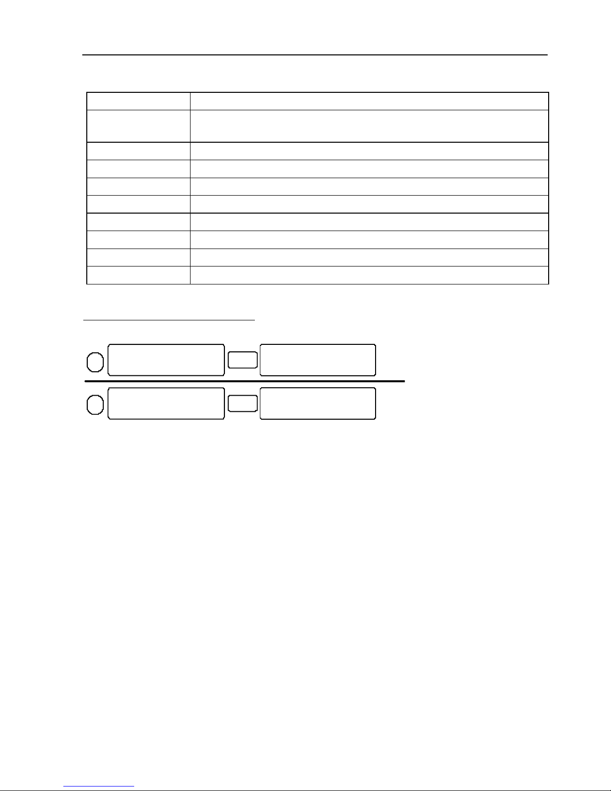
HUNTER-PRO Series Installation Guide 65
Screen Data
URL or IP Enter either the MS IP no. (e.g. 145.85.24.8) or URL (e.g.
www.cmsaddress.com). Use up to 47 characters including spaces.
Station port MS1 & MS2 NETsoft/PIMAnet port no.’s.
Upload port For future use
Web port For future use
Static IP IP no. for the net4pro
Default gateway The router address
DNS server To manually enter a DNS server address
Test Interval Enter time in minutes and seconds
Attempts to Fail No. of attempts to contact the MS before “comm. error” appears
Example: Entering IP no. or URL
MS1 URL/IP
145.85. 24.8
ENTR
URL 1 OR IP 1
www.myv endor.com/
customers/myname/
mypremises/
ENTR
MS #1 IP no.
MS #1 URL. The address is entered under the
restriction of 16 characters per line (and 47 in all) an
d
continue to the next screen (after pressing [ENTR])
1
2
This screen is left blank
Page 66
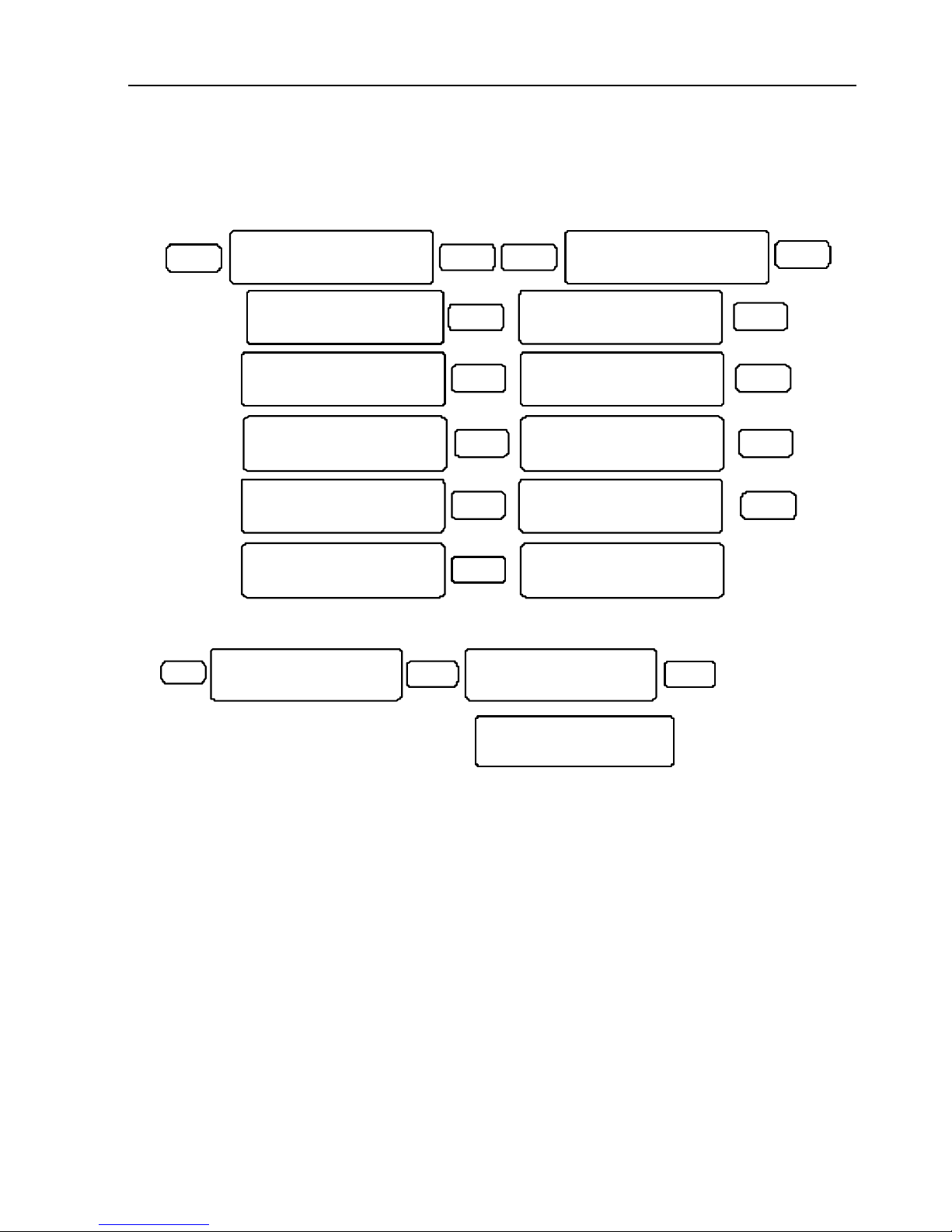
66 HUNTER-PRO Series Installation Guide
5.6 Key #4: Timers, Counters
Set the system’s timings for entry/exit delays, outputs tripping, faults response and more.
4
NE XT
NEXT
AC Report Delay
ENTER/NEXT/END
Phone Rprt Delay
ENTER/NEXT/END
NE XT
Burg. Rprt.Delay
ENTER/NEXT/END
NEXT
Soak Test Days
ENTER/NEXT/END
NEXT
Double Knock
ENTER/NEXT/END
NE XT
Cond. Zones Time
ENTER/NEXT/END
NEXT
Byps. Limit Time
ENTER/NEXT/END
NEXT
False Code
ENTER/NEXT/END
NE XT
Inactiv. Report
ENTER/NEXT/END
ENTR NE XT
T ime rs, Cou nter s
E NTE R/NEX T/EN D
O utpu t T imes
E NTER/ NEXT /END
NE XT
Ex t. Sir en Tim e
EN TER/ NEXT/ END
5.6.1 Entry/Exit Delays
3
ENTR ENTR
Timers , Cou nte rs
ENTER/ NEX T/E ND
Entry /Ex it De lay
ENTER /NE XT /END
Entry 1 2 Ex it
2 0 20 6 0
Set ‘Entry 1’ delay for all the zones (To use the ‘Entry 2’, refer to section 5.4.1,
parameter ‘T’) and the exit delay. Default entry delay is 20 seconds; exit, 60 seconds.
5.6.2 Output Times
Set the outputs type timing, i.e., the time in which the related PCB output is tripped. In
each output type screen press [ENTR] and set the time.
The HUNTER-PRO series has 3 trip times:
1. ‘0’: The output is tripped until the system is disarmed
2. 1-9998: The output is tripped for this time (in seconds)
3. 9999: The output is tripped for as long as the event (By an output type. see
further) that had triggered it exists. For example, the onboard relay is triggered by
and for as long a phone line failure remains. As soon as the fault is resolved the
output is switched off.
Page 67

HUNTER-PRO Series Installation Guide 67
Following is a table of the output types (see section 1.7) with their default timing.
[NEXT] Output type Timing (Sec.)
- Ext. Siren 240
X1 Int. Siren 240
X2 Burglary 240
X3 Anti-mask 240
X4 Special Burglary 1 240
X5 Special Burglary 2 240
X6 Smoke 240
X7 Fire 240
X8 Special Fire 240
X9 Panic 240
X10 Silent Panic 240
X11 Hold Up 240
X12 Medical 240
X13 Tamper 240
X14 Mains Fault 9999
X15 Low Battery 9999
X16 Phone Failure 9999
X17 Trouble 9999
X18 Zone Bypassed 9999
X19 GSM Fault 9999
X20 Comm. Fault 9999
X21 TAG Activation 240
X22 Door code 5
X23 W/L Remote 5
X24 Test 5
X25 Audio Device 60
X26 Remote control* 60
X27 Zone Open Hold** 0 (min.)
* The time an output remotely triggered remains triggered
** Energy saving feature: Can be used for automatically turn off air conditions and
lights at the end of the day.
“Zone open hold” works in conjunction with the ‘Zone Opened’ output type (an
event output type that follows the zones status): After setting the “Zone open hold”
time, any PCB output that is triggered by ‘Zone Opened’ output type (i.e. triggered
when any zone is violated) will remain triggered after the zone returns to normal
mode, for the time set in the “Zone open hold” time (unless the zone is violated
again first).
Page 68

68 HUNTER-PRO Series Installation Guide
5.6.3 AC Report Delay
Set the time (in minutes) a mains (AC) failure report will be delayed (Up to 250
minutes).
5.6.4 Phone Report Delay
This is a feature which is meant to prevent false telephone line alarms: The fault report
is delayed for the time (in minutes) set in this menu. If the line is normally clear it is
recommended to set the delay time to zero (No delay).
5.6.5 Burglary Report Delay
Burglary alarms will not be reported immediately to the MS if they occur within entry
delay, but delayed for the time set in this screen. If the system has been disarmed in
the mean time, the report will not be sent at all. If the entry delay is very short it is
recommended not to change the default time. This reduces superfluous reports.
5.6.6 Soak Test Days
Set the number of days a zone (Mostly, a zone that causes false alarms) will be in test
mode. During this period of time, any violation of the zone will neither be reported to
the MS nor trigger the alarm/private dialer. It will be displayed in the “Fast display”
mode and will only be logged in the memory log.
The max test period is 7 days. After this period the zone will automatically return to
normal operation. If set to “0” the zone returns to normal at midnight of the same day
the test begun. There is no limit of the number of soaked zones.
The soak zone menu is located under Tests (#0).
In PIMA display mode, the letter “T” indicates the zone is under a
test mode
5.6.7 Double Knock
Double Knock is a feature for reducing false alarms: A zone set as ‘Double knock’ will
alarm only when it is violated twice within a period of time which is set in this screen
(see “Zone Programming” section 5.4).
There is no limit with the no. of Double knock zones.
If a Double Knock zone is violated continuously, an alarm will
be set off after the preset time
5.6.8 Conditioned Zones Time
Set the time span (in seconds) for conditioned zones to set off an alarm, only if 2 of
them are violated within a pre-determined period of time, set in this screen (see “Zone
Programming”, section 5.4).
Page 69
HUNTER-PRO Series Installation Guide 69
5.6.9 Bypass Limit Time
Set the time (in minutes) in which a zone can be bypassed (by a user, during arming),
before it is automatically becomes armed again. This protects against burglary
preparation by bypassing zones before the system is armed.
5.6.10 False Code
Set the number of allowed keystrokes (max 24), after which the system reports the MS
and responds according to the system responses (see “System Responses” , section 5.8).
5.6.11 Inactivity Report
This feature serves as an indication if the system has not been armed (fully or partially)
for the number of days set in this screen. If so, a report is sent to the MS which can
then check the integrity of the system with the customer.
5.7 Key #5: General Parameters
ENT R
5
Gen. Parameters
ENTER/NEXT/END
General parameters are displayed in 2 consecutive screens.
5.7.1 First Screen
KD1E2EKAB2SMPZTF
--+-+--------+++
Par. Name Marking “+” means…
K State Key Switch (+) Toggle key (On/Off)
(-) Momentary key
D DC Siren DC Siren is installed
1 TAMPER 1 Connec. TMPR #1 output is active
E TAMPER 1 - EOL TMPR #1 output is protected by EOL circuit
2 TAMPER 2 Connec. (+) TMPR #2 output is active
(-) TMPR #2 output serves as zone #9
E TAMPER 2 - EOL TMPR #2 is protected by EOL circuit
K Key-> Home State Arming with a key arms to ‘HOME 1’
A Automatic-> HOME Automatic arming arms to ‘HOME 1’
B Byps. Zone in Au. Any opened zones are bypassed in auto-arming
2 2 EOL Resistors All EOL zones are protected by 2 resistors
S Siren beep in ARM The siren beeps once when arming the system.
When disarming with a key or remote control the
siren beeps twice.
M User Code-> Menu (+) Entering User code displays the user menu
(-) Entering User code arms/disarms the system
P Advanced Menu Enhanced communication menu is enabled
Page 70
70 HUNTER-PRO Series Installation Guide
Par. Name Marking “+” means…
Z - Not in use
T Byps. Tmpr. in Arm Arming is enabled with faulty tamper
F Byps. Fail in ARM Arming is enabled with system fault
Press [ENTR] to save and proceed to the second parameters screen.
5.7.2 General Parameters Second Screen
CLDSF 12 ZERP F CJAO
+---- -+ ---- - ----
Par. Name Marking “+” means…
C Light KP continu The keypad keys illuminate (weak) continuously
L Light KP in Alrm All keypads illuminate during alarms
D Light KP in Dely All keypads illuminate during exit/entry delays
S Buzzer In Alarm The Keypad buzzes in during alarms
F Enable Fast Arm Press the following keys until the exit countdown starts:
[1] to fully arm the system
[4] to arm the system to ‘HOME 1’ mode
[7] to arm the system to ‘HOME 2’ mode
1 Cancel HOME1 Del HOME1 entry delay time is ‘0’
2 Cancel HOME2 Del HOME2 entry delay time is ‘0’
Z Disp. Alrm in ON Alarmed zones are displayed when the system is armed
E Not in use -
R Retrigger Opn.Zn Triggered zones will be re-triggered and send reports to
the MS until they are closed or the system is disarmed
P Disp. Armed Part Armed partitions are displayed
F Final door Closing a delayed zone will terminate exit delay timing
C Full remote cont Enable full remote control (Mode B, including outputs)
J Report W/L Jamm. Wireless jamming is alerted & reported
A Part. AutoArming Auto-arming by partition is enabled
O Not in use
5.8 Key #6: System Responses
6
ENTR
ENTR
System Response
E NT ER / NE XT /E ND
Mains Fault
E N TE R/ NE X T/ EN D
SS AL
-- --
Set the system’s responses to 5 faults/events: Mains fault, low battery, phone line
fault, false code entry, and zone failure/tampering.
Page 71
HUNTER-PRO Series Installation Guide 71
The differentiation of responses between armed & disarmed
modes, as in other PIMA systems like the HUNTER-PRO 32, does
not apply to HUNTER-PRO series and has been replaced by the
parameter ‘L’. See the next table
Par. Response Mark “+” means…
S Activate Siren 1. When the system is armed, both the internal and external
sirens are set off in alarm
2. When the system is disarmed, only the internal siren is set
off in alarm
S Ext. SRN in OFF The external siren is activated in alarm even when the system is
disarmed
A Act. Burgl Output Activate the burglary output type
L No Daytime MS The system does not report the MS when it is disarmed
5.9 Key #7: Outputs Configuration
7
ENT R
ENTR
Output Configur.
ENTER/NEXT/END
External Siren
ENTER/NEXT/END
ENTR
Part. for OUT
++++++++++++++++
PD
-+
ENTR
Output Type
Output’s partit ions
Outp ut’s Polari ty
External Siren
External Siren
PCB’s (physical) output
Configure the PCB outputs and the output types (see section 1.7 to distinct between
the two). The outputs can be triggered based on partitions, i.e. be triggered only by
alarms generated in the allocated partitions.
By default, the output types are allocated to the most likely PCB outputs, so the
‘External siren’ output type, for example, is the default type for the PCB ‘Ext. SIREN’
output. It is not advisable to change these unless specific installation requirements.
5.9.1 PCB & Expanders Outputs
There are seven outputs on the system’s PCB: Ext. & Int. SIRENS, SMOKE, RELAY,
ON/OFF, ALRM, Audio Ctrl. The expanders' outputs are also set in this menu.
7
ENTR
Output Configur.
ENTER/NEXT/END
External Siren
ENTER/NEXT/END
p
Page 72
72 HUNTER-PRO Series Installation Guide
Press
[NEXT]
PCB/Expanders
Output
X1 Internal Siren
X2 RELAY
X3 SMOKE (reset detectors)
X4 ON/OFF
X5 ALARM
X6 Audio Control
X7 OUT-1000 Outputs
X8 I/O-R Outputs
X9 I/O-8N Outputs
5.9.2 Output Types
Following, is a table of the output types by their order in the menu. To clarify, the
process of programming is as follows:
Pick an output and press [ENTR]; Pick an output type and press [ENTR]; Set the
output partition/s and press [ENTR]; set the output polarity (see how further on) and
press [ENTR];
Output type What trips the PCB output?
External Siren Alarm from a zone programmed to trigger the external siren
output type
Internal Siren Alarm from a zone programmed to trigger the internal siren
output type
Burglary Alarm from ‘Burglary’ zone type*
Anti-Mask Alarm from ‘Anti-Mask’ zone type
Special Burglary 1 Alarm from ‘Special Burglary 1’ zone type
Special Burglary 2 Alarm from ‘Special Burglary 2’ zone type
Burglary - All
Types
All alarms from ‘Burglary’, ‘Special Burglary 1’ and ‘Special
Burglary 2’ zone types
Fire Alarms from ‘Fire’ zone type
Special Fire Alarms from ‘Special Fire’ zone type
Panic Alarms from ‘Panic’ zone type, or keypad panic code [*]+[#]
Silent Panic Alarms from ‘Silent Panic’ zone type
Hold-Up (Duress) Alarms from ‘Hold-Up (Duress)’ zone type, or keypad hold-up
code
Medical Alarms from ‘Medical’ zone type
Alarms - All Types All the alarms from all the zones
Audio Control Activating audio (MIC-200) or voice unit (VU-20N)
Zone Open Zone violation
Zone Bypassed Zone bypassing
*
All the zone types are programmed by default to activate the external siren in
response to alarm. To change this, see section 0 5.8.
Page 73

HUNTER-PRO Series Installation Guide 73
Output type What trips the PCB output?
Smoke Detector
Power
Resetting smoke detectors
Tamper Tamper switch opened
Zone Tamper/fail Zone tamper switch triggered or zone failure
Buzzer Keypad buzzer activated
Armed Arming the system
Installer Program Entering installer code
General Fault System general fault
MAINS Fault Mains fault
Low Battery Low battery fault
Phone Fault Phone fault
GSM Fault GSM fault
Communication
Fault
Failing to communicate with the MS
Not In Use Door Code Entering a door code
Wireless Remote
Pressing the [*] button in a remote control
Test Sending test report
Not In Use Not In Use Remote Control Activating an output remotely
Not Used Station ACK ACK received from the MS*.
* This output type is used for indication that a report that was previously sent to the
MS has been received. When an alarm from a zone programmed to set off the “Station
ACK” output type occurs, the PCB output programmed to be triggered by this output
type “waits” for the system to receive ACK. As soon as the ACK is received the output
is tripped for 10 seconds (and can turn on a bulb, for example).
5.9.3 Output Partitions
Set the outputs partitions (see drawing in section 5.9), i.e. define which partitions are
enabled to activate which output.
5.9.4 Polarity & Activation in Disarm
Set the polarity of the output and whether it will be activated when the system is
disarmed (See the drawing in section 5.9).
Par. Name When setting to “+”
P Polarity
<+=Pos.
‘+’: The output is normally tripped and is disconnected during alarms
‘-’: The output is switched to GND during alarms
D Active in
Disarm
‘+’: The output is tripped when the system is disarmed
‘-’: The output is tripped when the system is armed
Page 74
74 HUNTER-PRO Series Installation Guide
5.9.5 ‘Ext. Siren’ and ‘Int. Siren’ Outputs
These 2 onboard outputs are both high current outputs and can trigger any speaker
siren. However, the ‘Ext. Siren’ output can be triggered only when the ‘Int. Siren’
output is. As a result, the sirens connected to the HUNTER-PRO series can be activated
in one of 3 ways: Both the internal and external, the internal only & no siren at all.
It is recommended not to allocate to the ‘Ext. Siren’ and ‘Int. Siren’
PCB outputs any other but the same output types
5.9.6 Expanders’ Outputs
5.9.6.1 OUT-1000
7
ENTR ENTRB ACK
ENTR
O utp ut C on fig ur .
E NTE R/N EX T/E ND
O UT -10 00 Out put s
E NT ER/ NEX T/ END
O utp ut 1
X3
O utp ut 1
F ire
ENTR
Part. For OU T 1
++ +++ ++ +++ +++ +++
PD
-+ 1
ENTR
Expander
Expander’s output No.
O utput’s output type
Output’s partitions
Output’s polarity
Output’s No.
Configure the OUT-1000 (8 outputs expansion card) outputs. The screens are the same
as those of the PCB outputs.
Press [NEXT] to configure the I/O-R 8 relays expansion card and the I/O-8N and I/O16 outputs card
5.9.7 Examples for Programming the Outputs
1. ON/OFF output:
7
ENTR ENTR
NE XT
EN T R
Out put Co nfi gur .
ENT ER /NE XT/ END
O N/O FF O utp ut
E NTE R/N EXT /E ND
X4
Par t. For O UT 1
+++ --- -++ --- +++
PD
-+
ENTR
Pick an output
Set output type
Enable partitions to
activate the output type
Set output’s polarity
& active in disarm
ON /O FF O utp ut
Ar med
The procedure is as follows: First, pick the ON/OFF output. Then, determine what
output type will be allocated (trigger) to it. In this case, the default output type is
‘Armed’, so when the system becomes armed, the ON/OFF output is tripped.
Then, determine from within which partition/s this output can be triggered. Then set
the polarity of the output.
Page 75
HUNTER-PRO Series Installation Guide 75
2. ALRM output:
Configure the ALRM output so when any zone is opened, the output is tripped. To
do so, allocate the ‘Zone opened’ output type to the ALRM output.
7
ENTR
ENTR
NEXT
ENTR
O utp ut Co nfi gur.
E NTE R/NE XT/ END
AL ARM O utp ut
EN TER /NE XT/E ND
X5
P art . Fo r OU T 1
+ ++- --- ++- --+ ++
PD
-+
ENTR
Set output type
Enable partitions to
activate the output type
Set output’s polarity
& active in disarm
ON /OF F Ou tpu t
Zone Opened
3. OUT-1000 outputs
Set ‘Internal Siren’ output type to trigger output #4 on OUT-1000:
7
EN T R EN TR
NEXT
EN T R
Out pu t Co nf ig ur.
ENT ER /NE XT /EN D
OU T-1 00 0 O utp ut s
EN TE R/N EX T/E ND
Ou tp ut 4
X3
Ou tpu t 4
In ter na l S ire n
ENTR
Pa rt . F or O UT 1
++ ++ +++ ++ ++ +++ ++
PD
-+ 1
ENTR
Pick output No. 4
Set o utput’s output t ype
Set ou tput’s part itions
S et outp ut’s p olarity & activ e in disarm
Output’s No.
BACK
X3
5.10 Key #8: Full Programming
5.10.1 System Defaults
Initialize the system to factory defaults.
8 ENTR ENTR
Full Programming
ENTER/NEXT/END
System Defaults
ENTER/NEXT/END
Are you sure?
ENTER/NEXT/END
Press [ENTR] to confirm. A countdown ends with this message:
Syst.Defaulted
Press END
Press [END]
5.10.2 Local Download
8
ENTR EN TRNEXT
Full Programming
ENTER/ NEXT/END
Local Down load
ENTER/NEXT/END
Use this menu to program the HUNTER-PRO series with the COMAX upload/download
software. COMAX runs on a local computer that connects to the panel using LCL-11A
adaptor and the keypad (see section 4.1.2 and the COMAX user guide). Pressing
Page 76
76 HUNTER-PRO Series Installation Guide
[ENTR] causes the system to standby, waiting to receive data. Immediately press
‘Local’ icon
in COMAX to start the process. Wait until “Connected” message is
displayed on the COMAX status bar. You can now start downloading information.
5.10.3 Fast Load
8 EN TR ENTRBACK
Full Programming
ENTER/NEXT/END
Fast Load
ENTER/NEXT/END
Full
Select Prog. 1-7
- OR - NEX T
Communication
Select Prog. 1-7
1
...
7
Set the options for the PRG-896 fast programmer: The HUNTER-PRO series has 2
downloading options: full 7 different programs or only the communication parameters.
PRG-896 is programmed with COMAX software using DPR-33 adaptor
5.11 Key #9: Installer Code
EN TR
9
Installer Code
ENTER/N EXT/END
Installer Code
****** (4-6)
Set/change the Installer code. A code is 4 - 6 digits long.
If the Installer code begins with zero it is locked and cannot
be reset, in case of power loss. This is a security measure. If
this happens, please contact PIMA support team
5.12 Asterisk Key *: Express Programming Menu
*
Hour
00:00
For details, refer to section 4.5.
5.13 Key #0: Tests
Test menu has 9 sub-menus for testing the system’s hardwired and wireless zones, the
outputs, and the communication.
5.13.1 Walk-Test
0
ENTR
ENT R
Tests
ENTER/NEXT/END
Walk-Test
ENTER/NEXT/END
Tested0of9
Test all the line and wireless zones in the system. During the test, the display shows
the number of tested detectors out of the overall number of the detectors.
Page 77
HUNTER-PRO Series Installation Guide 77
The memory log keeps record of the test, including the number of zones triggered.
When the tests are over, press [ENTR]. If all zones were tested:
Untested Zones:
All Zones Tested
If not, the system displays the names of the zones not tested, in the following order:
Untested Zones:
UT:Zone 12
Untested Zones:
UT: Living Room
Untested Zones:
++++++++++++++++
Untested Zones:
Burglary
ENTR
ENTR
Zone No. Zone Name Zone’s Partitions
Zon
e Type
This test is useful for checking the system following an installation.
5.13.2 Single Zone Test
0 EN T R
S ing le Zon e Tes t
E NTE R/NE XT/END
NE XT
Sin gle Z one Te 32
ZON E 3 2
Press a
zone no.
ENTR EN TR
This test checks a single detector, hardwired or wireless: Press the desired zone
number. The first 8 zones are the onboard outputs and are named “on board zone”.
Pressing [ENTR] displays the zone’s name and then its partitions and type.
5.13.3 Wireless Test
ENTR
ENTR
NE XT
Wi rel es s Te st
EN TER /N EXT /EN D
Wai t fo r T ran s.
Zone 19 19
R SSI =3 (3= MA X)
X2
Zone Name Zone Number
RSSI level:
1= Weak
2= Medium
3= Excellent
Trigger a wireless detector. A
series of beeps will be pr oduced
by the keypad buzzer, once a
transmission is received
RSSI: Received Signal
Strength Indication
0
Testing a wireless zone is the same as testing any zone. The detector’s reception level
(RSSI) level is displayed in response to receiving a transmission (see next section). All
other screens match.
A transmission from a detector will be displayed, showing the detector’s RSSI, and be
registered in the memory log. This test is useful for finding the best location for
wireless detectors and their optimal regularity.
Page 78
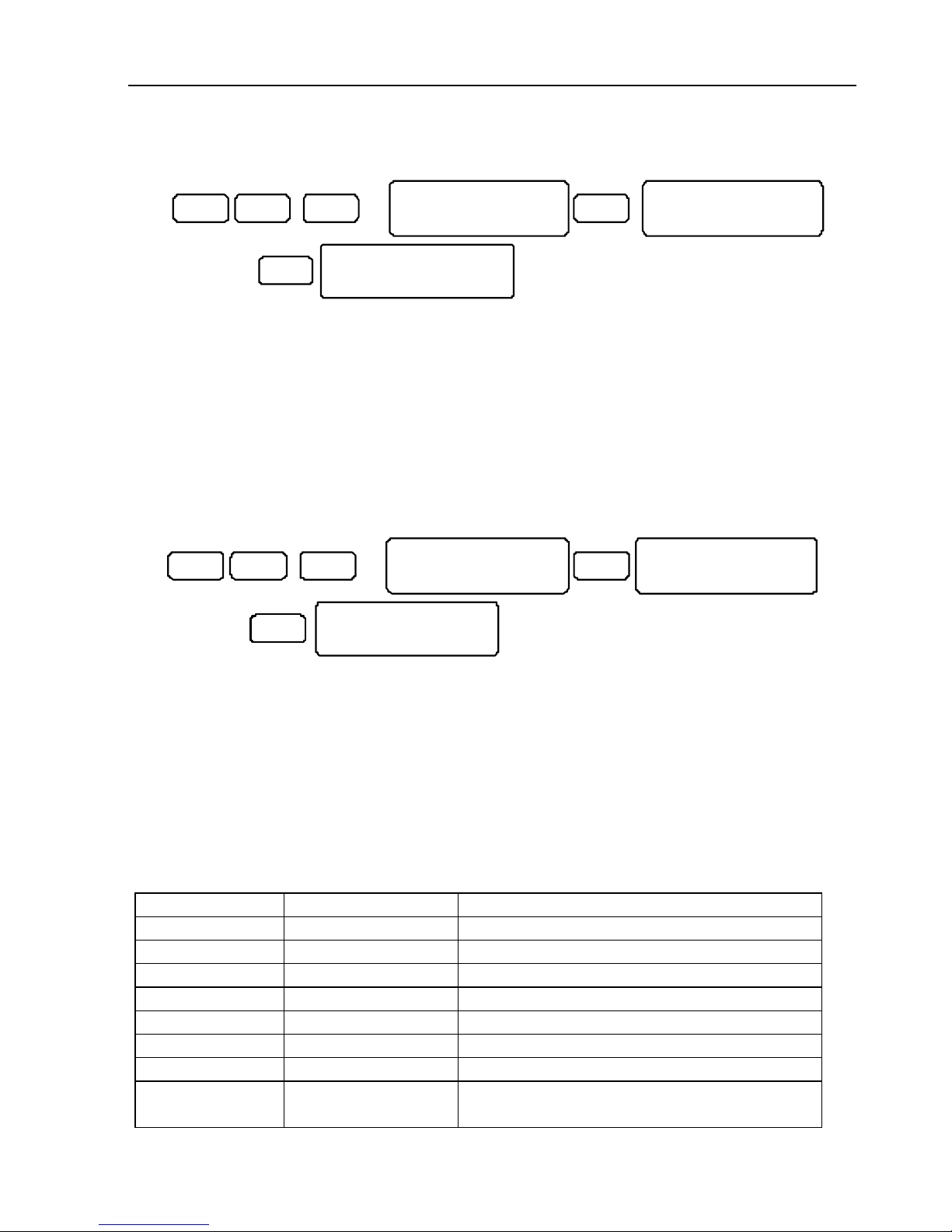
78 HUNTER-PRO Series Installation Guide
5.13.4 Set Soak Zone
0 ENTR ENTRNE XT
Set Soak Zone
EN TER /NE XT/E ND
X3
Zon e Num ber: 1
Ent r-Co nf #- Rst
ENTR
So ak Zo ne
Zo ne 1 -1
Set a zone to be soaked (tested). When a zone/detector is suspected in causing false
alarms, they can be tested. A test can last up to 7 days (to set the number of soak
days, refer to section 5.6.6).
All the events from a tested zone will neither trigger the alarm, nor be reported to the
MS. However, they will be logged.
When the soak test is over, the zone will automatically return to normal mode.
To manually change a zone status from soak to normal mode, press [#] in the zone
no. screen.
5.13.5 Outputs Test
0 ENTR ENTRNEX T
Out put s Te st
ENT ER/ NEX T/E ND
X4
ENTR
O utp ut s Tes t
E xte rn al Si ren
Exi t=E ND
This feature lets you test every output directly - locally and remotely. Pressing [ENTR]
trips the output for 10 seconds. Pressing [END] ends the test.
Testing the outputs has a great advantage - it allows the installer to define between
connection problems and programming faults: if a device does not work properly but is
triggered by the output test, then the problem lays with programming (or the device
itself) and not connection.
On the other hand, failing to trigger the external siren (for example) through the
output test, indicates a connection or other-than-programming problem.
These are the outputs test screens by their order:
Output Key Presses Details
External Siren [ENTR] Onboard Ext. output
Internal Siren [ENTR] [NEXT] Onboard Int. output
Relay [ENTR] [NEXT] X2 Onboard Relay output
Smoke Output [ENTR] [NEXT] X3 Onboard Smoke output
On/OFF Output [ENTR] [NEXT] X4 Onboard ON/OFF output
ALARM Output [ENTR] [NEXT] X5 Onboard ALRM output
Audio Contrl Out [ENTR] [BACK] X4 Onboard Audio Cont. output
OUT-1000
Outputs
[ENTR] [BACK] X3 Press [ENTR], pick an output and press
[ENTR] to trigger it
Page 79
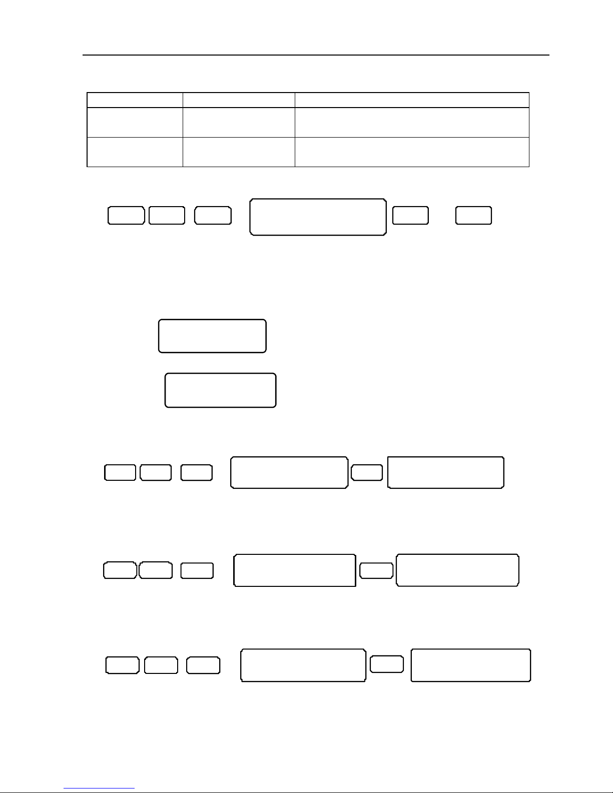
HUNTER-PRO Series Installation Guide 79
Output Key Presses Details
Exp IO-R
Outputs
[ENTR] [BACK] X2 Press [ENTR], pick an output and press
[ENTR] to trigger it
Exp IO-8
Outputs
[ENTR] [BACK] Press [ENTR], pick an output and press
[ENTR] to trigger it
5.13.6 MS Dialer Test
ENTR 1NEXT X5
Tes t M S D ia le r
Sel ec t T . N o. 1-4
0 4….
Test the Monitoring Station’s PSTN dialer: Press [1] to dial phone #1; Press [2] to do
so with phone #2, and so on.
When trying to test a no. that had not been programmed before, an error message is
displayed, asking to press [END]. The system then shifts automatically to the screen
where this information should be entered.
For example:
Set Ph. Connect!
Press END
. This error message occurs when trying to test the
MS radio without programming the account number first. When pressing [END] the
menu shifts to
Commun. Options
ENTER/NEXT/END
screen in “Communication” menu where this
parameter is entered.
5.13.7 GSM MS Test
ENTR ENTRBA CK
X3
Test MS GSM
ENTER/NEXT/END
Test MS GSM
Select T. No. 1-4
0
Test the MS GSM numbers. The test is similar to the PSTN test (See the
previous section).
5.13.8 Radio MS Test
ENT R ENTRBAC K
X2
Test MS Radio
ENTER/NEXT/END
Please Wait..
0
Test the long range radio transmitters, TRV/TRU-100. Pressing [ENTR] will send a
transmission test to the MS. No ACK from the MS can be received in this test.
5.13.9 GSM Signal Strength
0 ENT R
ENT R
BACK
X2
GSM Sig. Strength
ENTER/NEXT/END
GSM Sig.Strength
_________..
Strong signal:
_
Weak signal:
.
The GSM signal strength indication works as in a cell phone: If the reception is weak
(less than 8 squares) the GSM receiver needs to be relocated.
Page 80
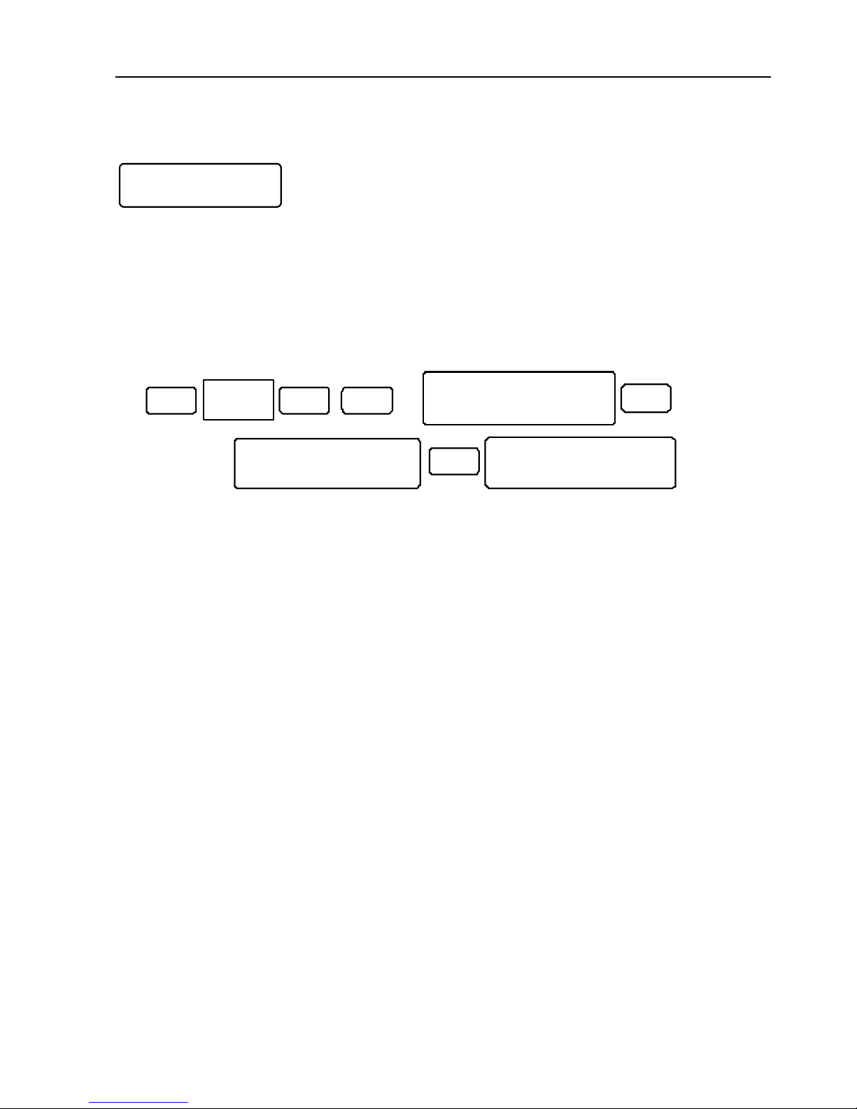
80 HUNTER-PRO Series Installation Guide
5.13.10 Network Statistics
L:T0 R0
G:T0 R0
This screen gives information regarding the network and GPRS. The top line shows the
PIMAnet™ IP network statistics and the bottom shows the GPRS. The numbers are the
no. of packets sent and received.
When the ‘L’ and ‘R’ values in each line are equal or almost equal, the connection is
OK. The values can be reset in coordination with the MS.
5.14 Locating a Zone in an Expander
EN T R
5
All Zones: 27
ZONE 27
EN T R
Display Type
All Zones
Installer
Code
NEX T
X3
All Zones: 27
Wireless Expand.
0
The “All Zones” display type gives detailed information on every zone and enables the
technician to quickly locate it. It is part of the User menu
Page 81
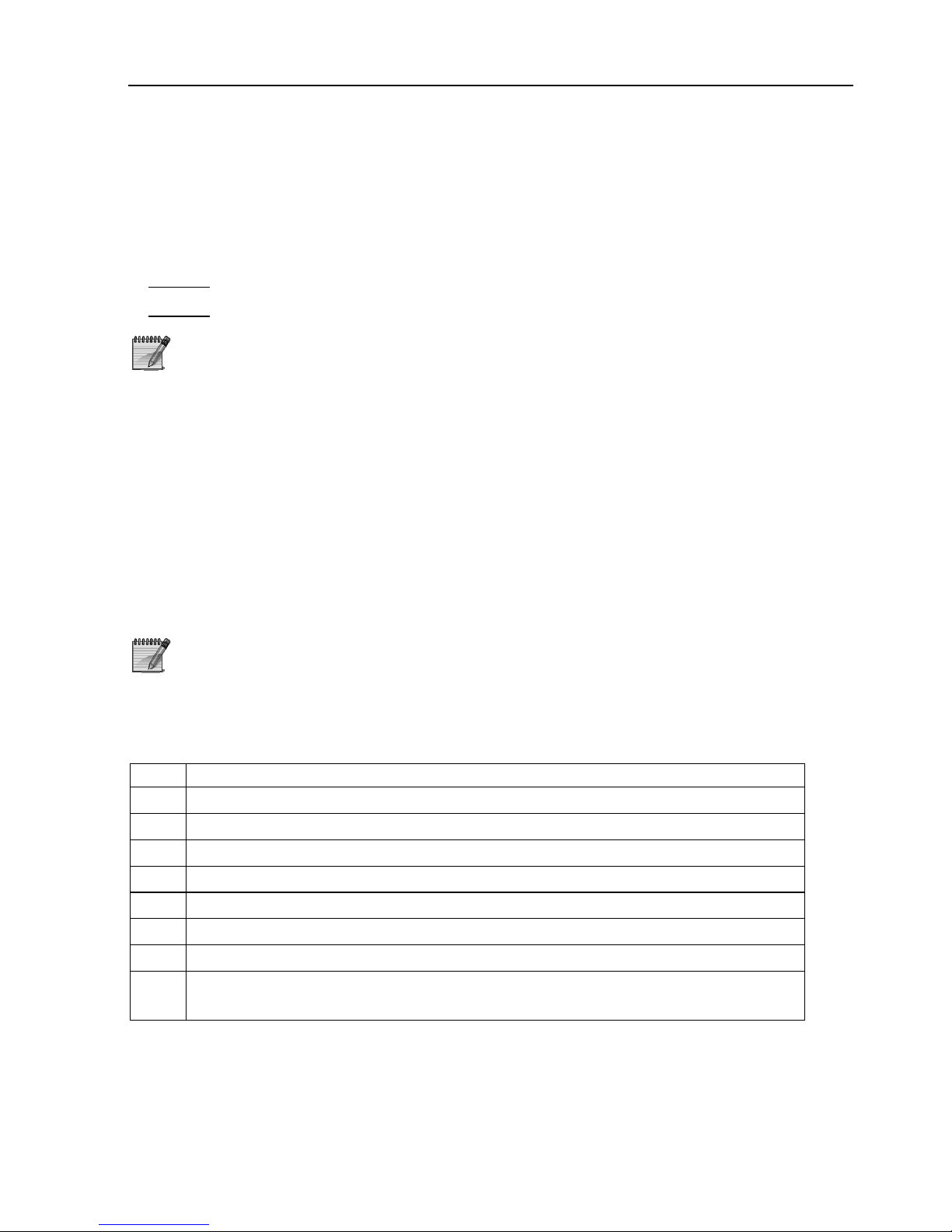
HUNTER-PRO Series Installation Guide 81
CH. 6. REMOTE CONTROL VIA TOUCH-TONE TELEPHONE
HUNTER-PRO series can be remotely controlled via any touch-tone telephone, including
a cellular. The system can be controlled in one of 2 options:
Mode A
: Basic commands, including arming and disarming (the default mode).
Mode B
: Full control, including triggering all the outputs
The entire chapter applies both when you call the system and
vice versa
6.1 Mode A
1. Dial the system’s telephone number
2. Wait for confirmation tone (a long tone followed with 2 beeps)
3. Enter Master Code
4. Wait for a status tone:
Continuous: The system is disarmed
Beeps: The system is armed
The system will not respond to commands while playing the
confirmation tone. It is important to wait until the confirmation
tone is over before pressing any telephone key
5. Press a key according to the next table. The system confirms the command
with 2 short beeps.
key Function
Turn off the external siren and stop the dialer from calling any other no.
Arm the system
Disarm the system
Arm the system to ‘Home 1’ mode
Trigger the onboard relay
Stop triggering the onboard relay
Arm the system to ‘Home 2’ mode
Listen in for one minute (available only with MIC-200). To extend listen in
time (in one minute), press
again as needed
While the system is engaged in remote session, the following message is displayed on
all connected keypads: “Other keypad in use”.
If the system does not receive any command for a period of 60 seconds, it shall
disconnect and return to normal mode. The system will remain in standby (displaying
“Other keypad in use”) for another 60 seconds, before returning to normal mode.
Page 82
82 HUNTER-PRO Series Installation Guide
6.1.1 Example for Mode A
Arming the system via telephone: Dial the system’s phone no. The system answers
wait for the confirmation tone to end Enter Main code Wait for command
confirmation tone to end Press [1]
6.2 Mode B
1. Repeat steps 1-4 in Mode A to contact the system.
2. To trigger an output, press [*] and the corresponding command from the following
tables.
3. To deactivate an output,
press [#] and the corresponding command from the
following tables.
General Commands PCB Outputs OUT-1000
Press Command Press Command Press Output
*
00 Turn off the external siren and
stop dialer
11 Ext. SIREN 21 #1
*
01 Arm the system 12 Int. SIREN 22 #2
#01 Disarm the system 13 RELAY 23 #3
*
04 Arm to ‘Home 1’ 14 SMOKE 24 #4
*
07 Arm to ‘Home 2’ 15 ON/OFF 25 #5
*
08 Start listening-in
16 ALARM
26 #6
17 Audio Ctrl 27 #7
28 #8
Relays on I/O-8N Expanders
Press I/O-8N Press I/O-8N Press I/O-8N
31 #1 37 #7 43 #13
32 #2 38 #8 44 #14
33 #3 39 #9 45 #15
34 #4 40 #10 46 #16
35 #5 41 #11
36 #6 42 #12
Page 83
HUNTER-PRO Series Installation Guide 83
I/O-R expander #1 I/O-R expander #2
Press Relay Press Relay Press Relay Press Relay
51 #1 55 #5 59 #1 63 #5
52 #2 56 #6 60 #2 64 #6
53 #3 57 #7 61 #3 65 #7
54 #4 58 #8 62 #4 66 #8
I/O-R expander #3 I/O-R expander #4
Press Relay Press Relay Press Relay Press Relay
67 #1 71 #5 75 #1 79 #5
68 #2 72 #6 76 #2 80 #6
69 #3 73 #7 77 #3 81 #7
70 #4 74 #8 78 #4 82 #8
Send system status via SMS
to the private dialer
Press Phone
Press Phone
91 #1
93 # 3
92 #2
94 # 4
6.2.1 Examples for Mode B
Activate the ‘Ext. SIREN’ output:
Dial wait for confirmation tone Enter Main code Wait for command confirmation
tone to end Press *11
Deactivate output #5 on OUT-1000:
Dial Wait for confirmation tone Enter Main code Wait for command
confirmation tone to end Press #25
Page 84
84 HUNTER-PRO Series Installation Guide
CH. 7. TROUBLESHOOTING
This chapter describes failures displayed on the keypad, various problems that may be
encountered due to improper programming, and options for troubleshooting failures
that might occur due to incorrect installation and/or programming.
7.1 Restoring the master & installer Codes
In case both these codes are not available:
1. Disconnect mains
2. Disconnect the battery
3. Wait 10 seconds and reconnect the battery
4. Wait for “Clock Not Set” to be displayed
5. Enter 5555 (default master code)
6. Press [9] and enter the new Master code (4-6 digits) and press [ENTR]
7. Press [END] to the main screen.
8. Press 1234 (default technician code) to enter the technician menu.
9. Press [9] and enter a new technician code (4-6 digits). Press [ENTR]
10. Connect mains.
11. Set time & date.
After connecting power, the system enables access to the menus
using the default master code (5555) for 30 seconds only. If access
does not occur during this time, the process needs to be repeated
The process is also useful for Installer code (Default code 1234),
with the exception of a code that begins with zero. In this case the
code cannot be reset and you need to call PIMA support
7.2 Faults Displayed on the LCD Keypad
In case a fault occurs, the red fault LED on the keypad flashes. The description of the
fault appears on the first line of the LCD Keypad at the right side. The faults are:
Fault Description & Repair
Clock Not Set Appears on first operation and when reconnecting after
power/battery failure. Set time & date
Low Battery 1. Make sure the battery fuse is intact.
2. Check battery charge voltage.
3. Wait 24 hours for recharging and recheck.
4. If the message stays on, replace battery.
Low Voltage Low PCB DC charge. Mostly occurs after long mains power failure
that causes the battery to get drained. Programming is
unavailable when this fault occurs. To repair: connect to mains
and replace battery if required.
Page 85
HUNTER-PRO Series Installation Guide 85
Fault Description & Repair
Mains Fault No mains power. If other appliances around are on, check the
system’s electric socket and fuse. If ok connect mains and the
PCB AC fuse
TAMPER 1 Tamper 1 is open
TAMPER 2 Tamper 2 is open
Zone Fault 1. In EOL protected zones: F - Cut, S - Short
2. In detectors wires: F L- Cut, S H- - Short
3. In wireless detectors: detector’s tamper is open
KEYPAD NOT
CONNECTED
No communication between the keypad and the PCB. Check the
following:
1. Disconnection between PCB’s “OUT” and keypad.
2. Keypad’s volta
g
e supply is lower than 13v. (verify that no more
than 8 keypads are connected)
3. Keypad fault - replace it.
4. PCB fault - replace it.
Phone Line Fault The system does not indicate any dial tone. The system checks
the phone line constantly.
To manually test the phone line, disconnect
any appliance connected to it
Keypad X Fault 1. Check keypad X ID (if possible)
2. Check keypad X wiring
3. If ID and wiring is OK, disconnect the keypad and connect it as
close as possible (50 cm max.) to the system box. If the keypad
still out-of-order, consult PIMA support
Detec. Vol. Fault Check for short in the detectors’ wires
Expander X Fault Expander’s X comm. or vol. connection fault
Expander X Tamper Expander’s X tamper is open
Keypad X Tamper Keypad’s X tamper is open
Other Keypad in use When more than one keypad is connected and one is being
programmed, the others will have this message on screen. This
message appears also when the system is being programmed
from a different source such as remote programming via
computer and telephone.
GSM-200 faults
GSM Unit Fault Connection problem or fault in GSM-200 receiver
GSM Comm. Fault GSM-200 to MS1 connection problem
GSM Link Fault Low reception or jamming in GSM channel
SIM Card Fault No SIM card installed in GSM-200 or SIM card fault
GSM Com. Fault 2 GSM-200 to MS2 connection problem
For further information on GSM-200 refer to the GSM-200 guide
Page 86
86 HUNTER-PRO Series Installation Guide
Communication faults
W/L Unit Tamper Wireless receiver’s tamper is opened or out-of-order. Check that
its cover is closed
For further information on I/O-WN, refer to the I/O-WN guide
Check Keypad
number
Keypad’s ID does not match the programmed no. of keypads
MS. Com. Fault Failure to communicate with the MS including in test mode.
This fault appears if the HUNTER-PRO communicator cannot
transfer reports to MS. Possible reasons are incompatible protocol
or phone line failure.
Check the following:
The telephone line is properly connected to the LINE
terminal blocks.
In Communication menu (section. 5.4) the “P” for telephone
is programmed with “+”.
At least one MS telephone number is programmed.
Telephone account ID for MS is other than 0.
Comm. format is compatible with the one used in the MS.
Correct telephone numbers have been entered.
If the system is connected to an extension of a private
switchboard a prefix has been programmed.
SMS Com. Failure Communication failure between the system and the provider’s
SMS center
Install SMS Unit SMS-100 unit is not installed
Network Fault Communication failure between the system and the PIMAnet card.
IO-R X Fault Fault in I/O-R relay expander
IO-R X Tamper I/O-R tamper is open
IO-R X Voltage Low voltage to I/O-R
Wireless Jamming Radio channel is jammed
IO-8 X Voltage Low voltage to I/O-8
Supervision: Wireless detector ceased to send reports to the system
System Error The EPROM version and the system’s software version do not
match. Contact PIMA support
If more than one fault occurs simultaneously they will be displayed
one by one
Page 87

HUNTER-PRO Series Installation Guide 87
7.3 Additional Faults
7.3.1 MS Comm. Fault
The system has preset to test all aspects of communication to MS: Press [6] for 2
seconds and enter technician code. All testing process will be displayed on the keypad.
7.3.2 MS Radio Fault
Make sure that:
1. The wiring between system and radio receiver is ok.
2. Radio account no. is other than ‘0’.
3. Comm. format is compatible with the one used in the MS
4. The receiver’s antenna is intact, not bended and is attached vertically.
5. If the antenna is installed on a separate surface, check its wires.
7.3.3 Private Dialer Fault
Make sure that:
1. The telephone line is properly connected to the LINE terminal blocks.
2. At least one private telephone number is programmed.
3. Correct telephone numbers have been entered
4. In Communication menu the “P” for telephone is set to “+”.
5. In Communication/Private Dialer menu the parameters are programmed.
6. If the system is connected to an extension of a private switchboard a prefix has
been programmed.
Disarming immediately after alarm will stop the dialer. To test the
dialer, arm the system and wait for dialing
7.3.4 Incoming Calls Fault
If the system does not receive calls, make sure that:
1. In Communication menu (section. 5.4) the “P” for telephone is set to “+”.
2. The programmed number of rings exceeds its limit.
3. The telephone line is properly connected to the LINE terminal blocks.
7.3.5 Tamper
TAMPER 1: Tamper 1 is triggered.
TAMPER 2: Tamper 2 is triggered.
Page 88
88 HUNTER-PRO Series Installation Guide
7.3.6 Auto-Arming & Auto-Arming by Partition
Make sure that:
1. Auto-arming start time is programmed (see HUNTER-PRO series User guide).
2. System time is correct.
3. The desired partition is programmed as so.
7.3.7 Violating a Zone does not Set-off the Alarm
Make sure that:
1. The zone is neither temporarily nor permanently bypassed.
2. The zone is programmed to the desired responses (sirens, relay, etc.)
3. The zone is programmed to only one partition.
4. The detectors are in order and installed correctly.
5. Zone sensitivity is correct.
6. Zone conditioning is correct.
7. Zone no. of pulses is correct.
8. Zone is not programmed as soak zone.
7.4 MS Report Formats & Codes
7.4.1 Pulse Formats
Name Rate (pps) ACK (Hz) Error Control ID Event A B
3 - 1 162 1
3 - 2 163 1
4 - 1 162 129
Double Round
4 - 2 163 129
3 - 1 162 65
3 - 2 163 65
4 - 1 162 193
1400
Checksum
4 - 2 163 193
3 - 1 162 17
3 - 2 163 17
4 - 1 162 145
Double Round
4 - 2 163 145
3 - 1 162 81
3 - 2 163 81
4 - 1 162 209
Ademco
Slow
10
2300
Checksum
4 - 2 163 209
Page 89
HUNTER-PRO Series Installation Guide 89
Name Rate (pps) ACK (Hz) Error Control ID Event A B
3 - 1 170 1
3 - 2 171 1
4 - 1 170 129
Double Round
4 - 2 171 129
3 - 1 170 65
3 - 2 171 65
4 - 1 170 193
1400
Checksum
4 - 2 171 193
3 - 1 170 17
3 - 2 171 17
4 - 1 170 145
Double Round
4 - 2 171 145
3 - 1 170 81
3 - 2 171 81
4 - 1 170 209
Silent
Knight
Fast
14
2300
Checksum
4 - 2 171 209
3 - 1 208 1
3 - 2 209 1
4 - 1 208 129
Double Round
4 - 2 209 129
3 - 1 208 65
3 - 2 209 65
4 - 1 208 193
Franklin 20 1400
Checksum
4 - 2 209 193
3 - 1 208 17
3 - 2 209 17
4 - 1 208 145
Double Round
4 - 2 209 145
3 - 1 208 81
3 - 2 209 81
4 - 1 208 209
Franklin 20 2300
Checksum
4 - 2 209 209
3 - 1 82 17
3 - 2 83 17
4 - 1 82 145
Universal
HighSpeed
20 2300 Double Round
4 - 2 83 145
3 - 1 82 81
3 - 2 83 81
4 - 1 82 209
Universal
HighSpeed
20 2300 Checksum
4 - 2 83 209
Page 90
90 HUNTER-PRO Series Installation Guide
Name Rate (pps) ACK (Hz) Error Control ID Event A B
3 - 1 120 1
3 - 2 121 1
4 - 1 120 129
Double Round
4 - 2 121 129
3 - 1 120 65
3 - 2 121 65
4 - 1 120 193
Radionics 40 1400
Checksum
4 - 2 121 193
3 - 1 120 17
3 - 2 121 17
4 - 1 120 145
Double Round
4 - 2 121 145
3 - 1 120 81
3 - 2 121 81
4 - 1 120 209
Radionics 40 2300
Checksum
4 - 2 121 209
7.4.2 DTMF Formats
Name Rate (pps) ACK (Hz) Error Control ID Event A B
3 - 1 0 2
3 - 2 1 2
4 - 1 0 130
Double Round
4 - 2 1 130
3 - 1 0 66
3 - 2 1 66
4 - 1 0 194
1400
Checksum
4 - 2 1 194
3 - 1 0 18
3 - 2 1 18
4 - 1 0 146
Double Round
4 - 2 1 146
3 - 1 0 82
3 - 2 1 82
4 - 1 0 210
DTMF
2300
Checksum
4 - 2 1 210
Contact
ID
0 230
1400 0 5
PAF™
2300
0 21
NPAF™
EPAF™
Call PIMA
support
Page 91
HUNTER-PRO Series Installation Guide 91
CH. 8. SUPPLEMENTARY PRODUCTS FOR THE
HUNTER-PRO SERIES
RXN-400 - Small LCD Display
RXN-410 - Large LCD Display
RXN-400 ACE – LCD Display
W/RFID Tag
SMS-100 - SMS Generated Via PSTN
GSM-200 - GSM/GPRS Transmitter
net4pro (Network) – TCP/IP Module
TRV-100 - VHF Radio Transmitter
TRU-100 - UHF Radio Transmitter
MCT-234 - Key Fob
MCT-201 WP – Panic Pendant
MCT-302 - Magnetic Contact
NEXT PIR MCW – Supervised PIR
VU-20N – Dual Voice Message module
MIC-200 - Microphone
RXN-416 – For 16 Zones
RXN-9 – For 9 Zones
Wireless Technician Keypad
RXN-200 - Anti-Vandal (IP65)
EXP-PRO UNIV – 8 Zones, Local
I/O-8N – 8 Zones, Remote
I/O-16 - 16 Zones, Remote
I/O-WN – 32 Ch. Wireless receiver
I/O-R – 8 Relays, Remote
OUT-1000 – 8 Open Collectors, Local
LCL-11A – Serial Interface
PRG-896 – Fast Programmer
LCD Keypads
Voice Accessories
Wireless Accessories
System Expanders
Special Keypads
Communication Modules
Led Keypads
Programming Modules
Page 92

92 HUNTER-PRO Series Installation Guide
INDEX
Accessories
MIC-200, 12, 37, 51, 72, 81, 91
PRG-896, 42
VU-20N, 37, 38
Comax, 42, 43, 56, 60, 75, 76
Enhanced Communication Menu,
47
Expanders
EXP-PRO, 13, 21, 22, 23, 48, 91
I/O-16, 23, 26
I/O-8N, 12, 14, 21, 23, 24, 72, 74,
82, 91
I/O-R, 21, 23, 26, 50, 72, 74, 83,
86, 91
I/O-WN, 12, 21, 23, 27, 40, 41, 48,
86, 91
I/O-WN programming, 49
Max. No., 21
OUT-1000, 13, 21, 31, 72, 74, 75,
78, 82, 83, 91
Programming, 48
Express Programming, 45
Keypads
ACE, 32
RXN-400/410, 32
Setting the keypads, 49
VKD-1, 33
Network Interface
net4pro, 9, 61, 64, 65
Output Types, 13, 72
Partitions
Example A, 15
Example B, 16
Example C, 17
Partitioning, 15
Serial interface
LCL-11A, 42, 43, 75
Transmitters
GSM-200, 9, 12, 36, 59, 60, 85, 91
SMS-100, 9, 12, 60, 64, 86, 91
TRV/TRU-100, 6, 9, 11, 12, 35, 36,
79
 Loading...