

Page 1
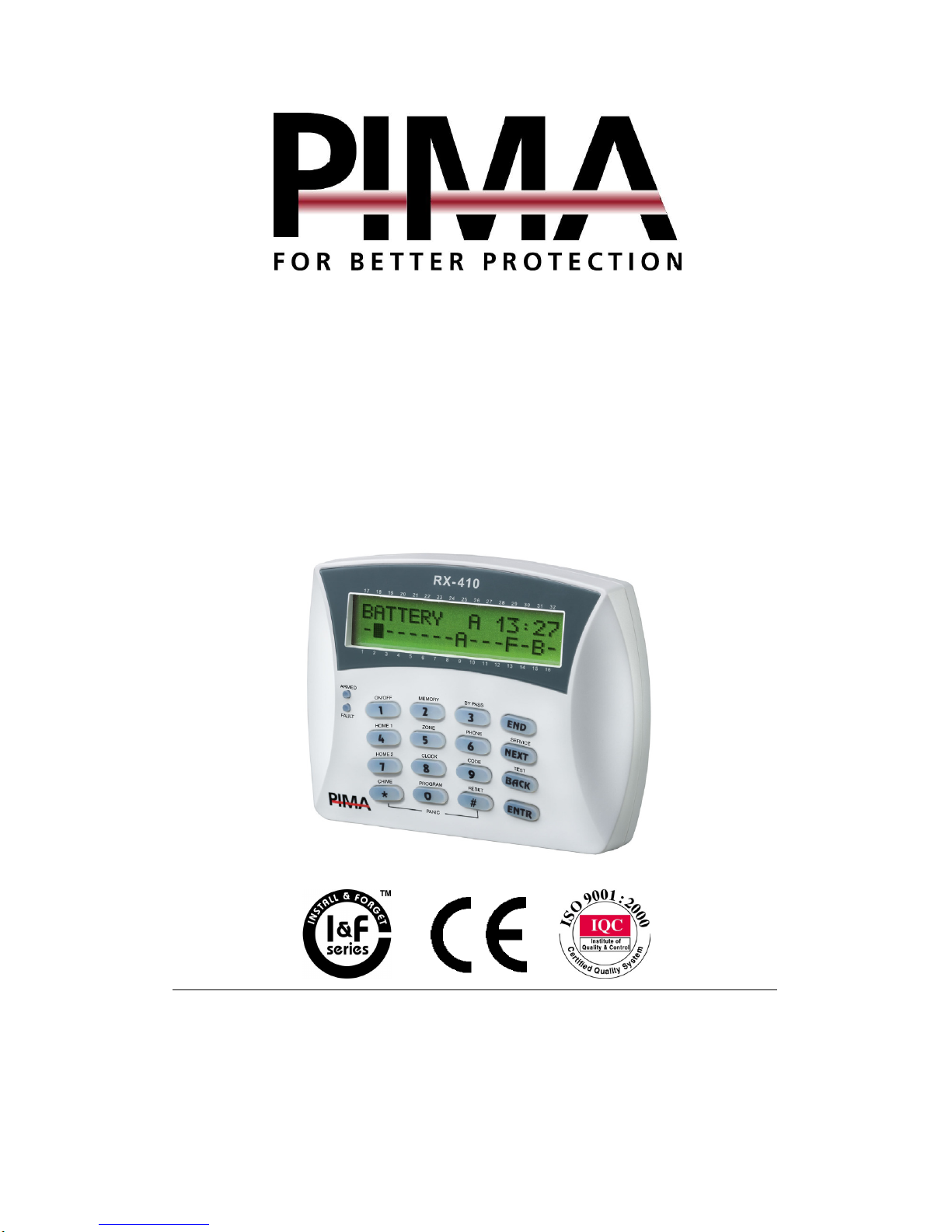
HUNTER-PRO 32
Intruder Alarm
System
User Manual
5 Hatzoref Street, Holon 58856, Israel
℡ +972-3-5587722 +972-3-5500442
PIMA Electronic Systems Ltd.
Page 2

HUNTER-PRO 32 Intruder Alarm System - Installation Manual
2
PIMA Electronic Systems Ltd. does not represent that its Product may not
be compromised and/or circumvented, or that the Product will prevent
any death, personal and/or bodily injury and/or damage to property
resulting from burglary, robbery, fire or otherwise, or that the Product will
in all cases provide adequate warning or protection. The User
understands that a properly installed and maintained equipment may only
reduce the risk of events such as burglary, robbery, and fire without
warning, but it is not insurance or a guarantee that such will not occur or
that there will be no death, personal damage and/or damage to property
as a result.
PIMA Electronic Systems Ltd. shall have no liability for any
death, personal and/or bodily injury and/or damage to property
or other loss whether direct, indirect, incidental, consequential
or otherwise, based on a claim that the Product failed to
function.
Warning: The user should follow the installation and operation
instructions and among other things test the Product and the whole
system at least once a week. For various reasons, including, but not
limited to, changes in environment conditions, electric or electronic
disruptions and tampering, the Product may not perform as expected.
The user is advised to take all necessary precautions for his/her safety
and the protection of his/her property.
This document may not be duplicated, circulated, altered, modified,
translated, reduced to any form or otherwise changed; unless PIMA’s
prior written consent is granted.
All efforts have been made to ensure that the content of this manual is
accurate. Pima retains the right to modify this manual or any part
thereof, from time to time, without serving any prior notice of such
modification.
Please read this manual in its entirety before attempting to program or
operate your system. Should you misunderstand any part of this manual,
please contact the supplier or installer of this system.
Copyright 2004 by PIMA Electronic Systems Ltd. All rights reserved.
You can contact us at: PIMA Electronic Systems Ltd., 5 Hatzoref St.,
Holon 58856, Israel. http://www.pima-alarms.com
Page 3

HUNTER-PRO 32 Intruder Alarm System - Installation Manual
3
TABLE OF
CONTENTS
CHAPTER 1: INTRODUCTION .................................................4
1.1 Main Features HUNTER-PRO 32 .........................................5
1.2 Safety Precautions ............................................................5
1.3 Signs and Abbreviations Key ..............................................6
CHAPTER 2: KEYPADS ............................................................7
2.1 Display Screen ..................................................................8
2.2 Keys’ Function ................................................................10
2.3 Entering User Menu.........................................................11
CHAPTER 3: ARMING & DISARMING THE SYSTEM ..............13
3.1 Arming/Disarming via Keypad .......................................... 14
3.2 Arming/Disarming with Remote Control
3.3 Arming/Disarming with Key..............................................17
3.4 Automatic Arming ...........................................................17
3.5 Disarming the System .....................................................19
3.6 Remote Control via Touch-tone Phone
CHAPTER 4: PROGRAMMING AND OPERATION...................22
4.1 Programming Codes ........................................................22
4.2 Programming Time and Date ...........................................31
4.3 Private Dialer Telephone Numbers ...................................31
4.4 Chime ............................................................................33
4.5 Alarm .............................................................................34
4.6 Panic..............................................................................35
4.7 Smoke and Fire Detectors Alarm ...................................... 35
4.8 System Tests ..................................................................35
4.9 Canceling Keypad Buzzer .................................................36
4.10 Bypassing Zones ............................................................36
4.11 Memory Log .................................................................. 36
4.12 System Display Types ....................................................38
...............................16
...............................20
CHAPTER 5: TROUBLESHOOTING
..............................................40
Page 4
HUNTER-PRO 32 Intruder Alarm System - Installation Manual
4
CHAPTER 1:
INTRODUCTION
Congratulations on your purchase of the HUNTER-PRO 32 Intruder
Alarm System! Much care has been taken in developing the
HUNTER-PRO Intruder alarm system, which will provide you with
unprecedented peace of mind. The HUNTER-PRO user-friendly
operation and advanced features will professionally protect your
home or business.
HUNTER-PRO 32 Intruder Alarm System contains numerous features
that allow it to befit the customer’s individual needs, and yet remain
easy to program and use both by the customer and the technician.
Therefore, it is important to read this manual from cover to cover in
order to familiarize yourself with the system and take full advantage
of its features. To assure optimal safety and security, you should
test the HUNTER-PRO 32 Intruder Alarm System once a week.
For any further questions, please do not hesitate to contact your
local PIMA distributor or PIMA directly at:
PIMA Electronic Systems Ltd.
Tel.: +972–3–558 7722
Fax: +972–3–550 0442
Email: [email protected]
Up to date literature is available to download from our website:
www.pima-alarms.com
Page 5

HUNTER-PRO 32 Intruder Alarm System - Installation Manual
1.1 Main Features HUNTER-PRO 32
8 to 32 zones with wireless add-on, local, and remote bus expanders
Supports a wide range of partition options:
5
Full supervision data of wireless detectors (life signal, low battery,
fault)
Comprehensive Zone Tests for flawless installation: Walk Test, Soak
Test, etc.
Two options for viewing system status:
Four Subscriber dialing numbers with optional voice message
Four Monitoring Stations phone numbers
PIMA unique Integrated Digital Communicator (telephone, long-range
radio)
Supports split and double reporting with different account IDs
LCD keypad with multilingual Menu-Driven screens for easy
programming and operation
Up to 16 partitions each with it own Account ID and Users
Up to 8 subsystems each with different keypads, IDs, etc.
“PIMA” Style: Status of all 32 zones is displayed
simultaneously
Detailed: Scrolling events, zones’ and system’s status
Many alternatives for easy programming (Keypad, Fast Programmer,
Local/Remote download software)
Up to 28 user codes with various authorization levels
Easy and user friendly operation with single key operation
Various accessories (microphone, voice unit etc.)
Memory Log up to 410 events (100 are non-volatile)
Automatic Arming at a preset time and/or after a preset silence time
System remote control via any touchtone telephone
1.2 Safety Precautions
Your Hunter alarm system has been registered with the CE in
accordance with EN 60950 of its rules. The CE requires us to tell you
the following information:
Page 6

HUNTER-PRO 32 Intruder Alarm System - Installation Manual
6
To reduce the risk of fire or electric shock, do not expose this
alarm system to rain or moisture.
Do not open the door of the alarm system. Dangerous high
voltages are present inside of the enclosure. Refer servicing to
qualified personnel only.
This alarm system should be used with AC 230V, 50Hz. To
prevent electric shocks and fire hazards, do NOT use any other
power source.
Do not spill liquid of any kind onto the unit. If liquid is
accidentally spilled onto the unit, immediately consult a qualified
service.
Install this product in a protected location where no one can trip
over any line or power cored. Protect cords from damage or
abrasion.
Disconnect all sources of power supply before proceeding with
the installation.
Connect the AC wires to the terminal block on the PCB as
marking. Pay attention to polarity.
1.3 Signs and Abbreviations Key
Regular key press
Long key press, until confirmation beep is heard
Press this key at any programming stage in order to
return to root screen
Default Master Code: 5555
Enabled User Code: A code enabled, by Master Code, to enter
User Menus
LCD Zone Numbers: Referring to the frame of zones engraved
above and below the LCD display window,
indicating the zones’ numbers.
Page 7
y
HUNTER-PRO 32 Intruder Alarm System - Installation Manual
7
CHAPTER 2:
KEYPADS
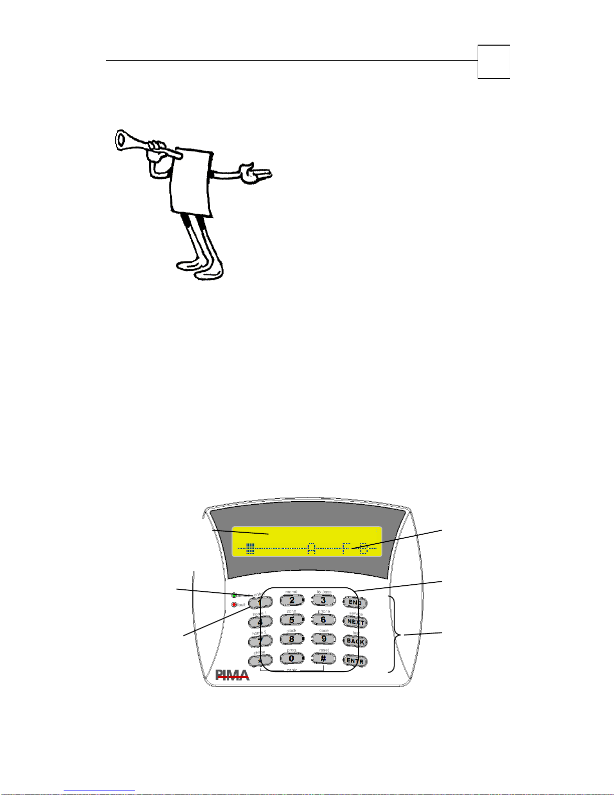
HUNTER-PRO 32 works with PIMA’s LCD keypads: RXN-400 and
RXN-41O, especially designed for maximum simplicity, durability and
decorative design. The keypad is used for arming, disarming and
programming the system as well as displaying time and date, system
status information, events and defaults, memory log and more.
Both keypad models are identical, except for the size of the display
screen:
RXN-410: Large screen 23 x 97 mm
RXN-400: Small screen 15 x 60 mm
Up to eight keypads can be connected to the system
RXN-410
System display:
Date & Time
ARM LED
(green)
Fault LED
(red)
1 JAN 04 12:40
System display:
Zones Status
Num & Function
keys
Navigation &
Programming
ke
s
Page 8
17 18 19
20
21
22 23 24 25 26 27 28 29 30 31 32
T
t
HUNTER-PRO 32 Intruder Alarm System - Installation Manual
8
2.1 Display Screen
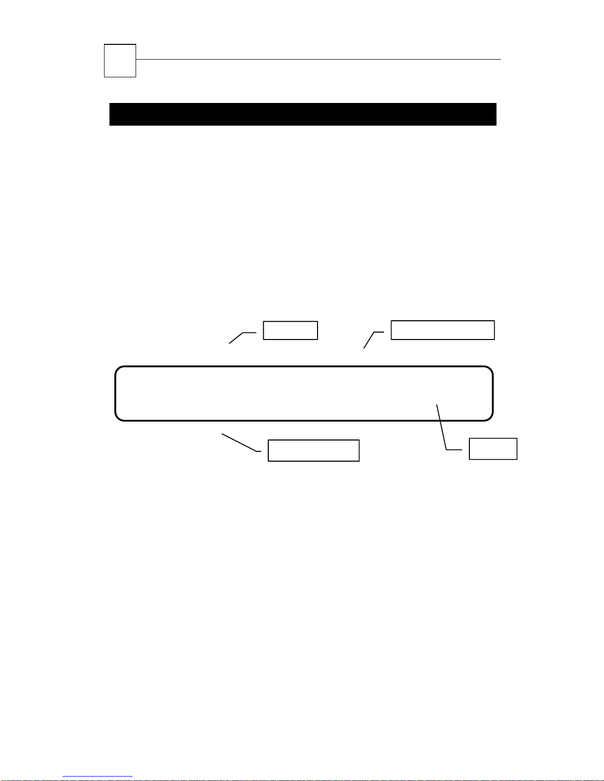
The display screen has two lines with 16 characters each. The upper
line displays the time and the date. The lower line displays data
regarding the
system, such as events, faults and zone status.
The user can choose between two display types: scrolling (fast zone
display) and PIMA display:
2.1.1 Scrolling
The zone and event screens automatically interchange and display
their status in a chronological order.
Date
System status
4 J A N 04 PS00:22
Vo l t a ge
1 2 3 4 5 6 7 8 9 10 11 12 13 14 15 16
Event/Faul
ime
Upper Line Display
Time and date
System status displayed between time and date:
P System communicating or testing PSTN line
S Siren ON
R Relay ON
T System reporting to Monitoring Station via radio transmitter
Lower Line Display
Events and faults
Opened zones (OP)
Page 9
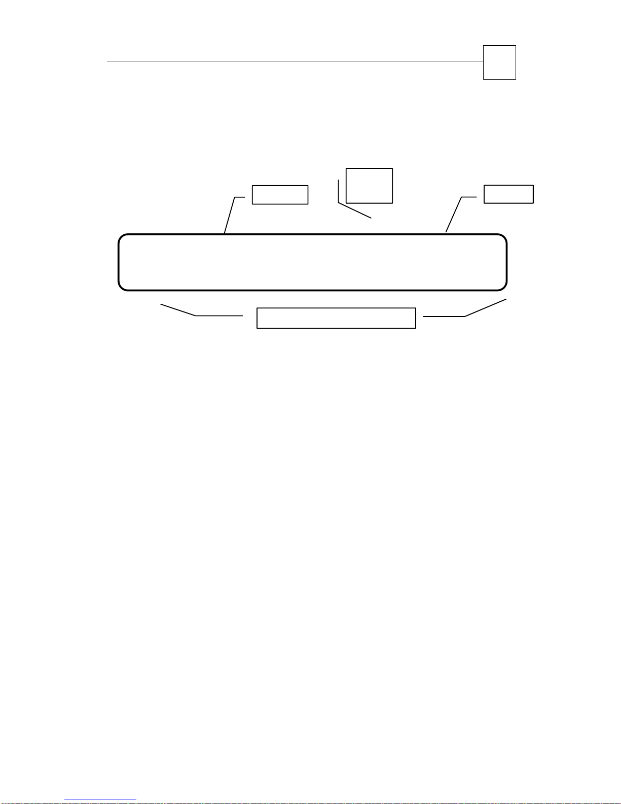
17 18 19
20
21
22 23 24 25 26 27 28 29 30 31 32
_
_
T
HUNTER-PRO 32 Intruder Alarm System - Installation Manual
2.1.2 PIMA Display
All events and zones displayed in a single screen using signs and
abbreviations
System
status
4
J A N 04 PS00:22
9
ime Date
-B
1 2 3 4 5 6 7 8 9 10 11 12 13 14 15 16
Upper Line Display
Time and date if system has 16 or les zones. If more, upper line
displays data like the lower line.
Lower Line Display
The following signs appear above (or below when in upper line) the
zone number/partitions that encircle the LCD screen:
- Closed zone
- - F--
Zone Status and Events
-------
_ Opened zone
B Bypassed zone
A Alarm zone (zone triggering alarm)
C Chime zone
S Shortcut zone (zone was shortcut)
F Failed zone (disconnected)/Tamper event (in a wireless
detector)
L Low battery in wireless detector
V Supervision signal: Wireless detector did nor report test to
system
Page 10
HUNTER-PRO 32 Intruder Alarm System - Installation Manual
10
NOTE:
If technician selected PIMA display, the system will not display the
zone status during faults. Only after faults resolved, PIMA Display
renews.
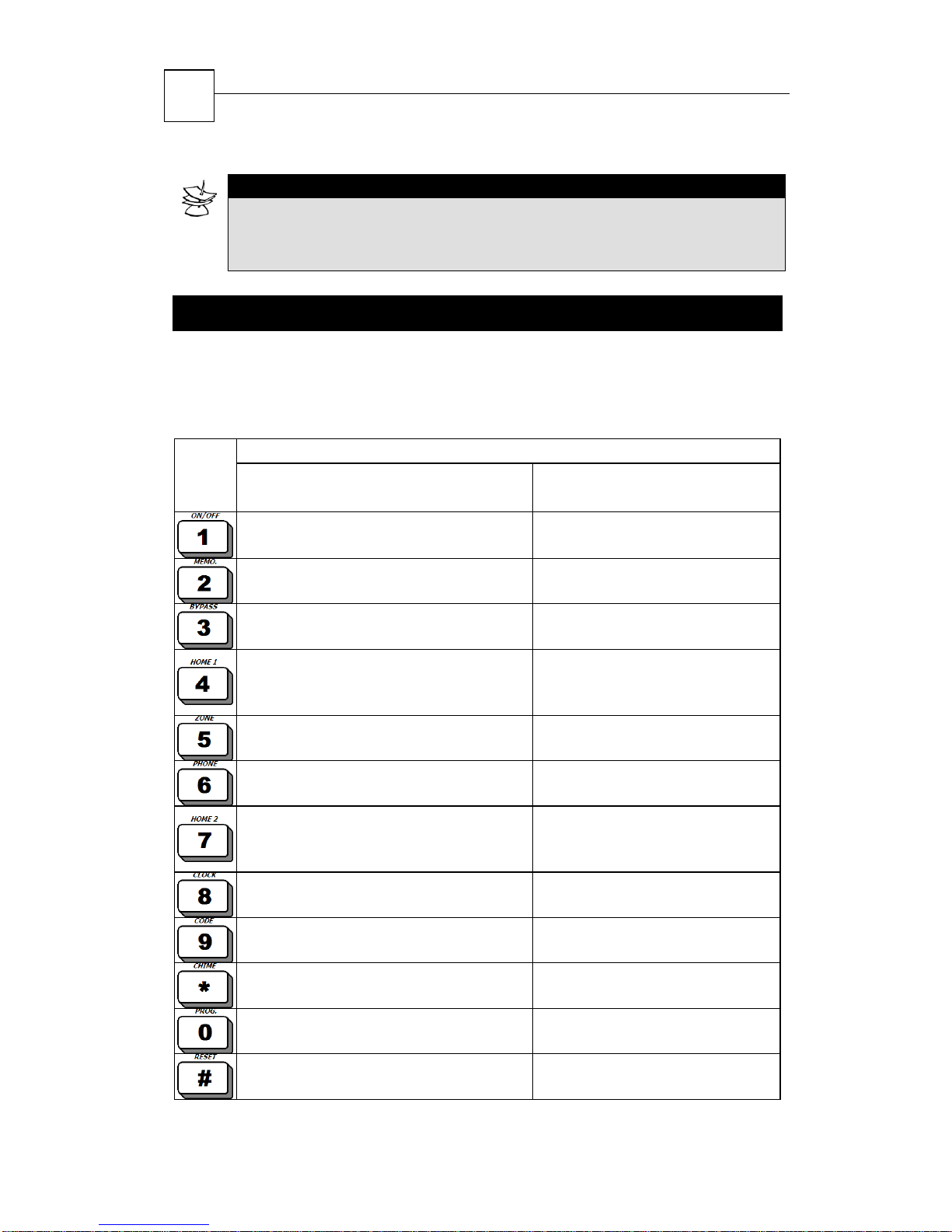
2.2 Keys’ Function
Operating and programming the system commences by first entering the
Master Code and then pressing any further required keys. However, a
number of keys enable certain actions by a single long press, without the
Master Code:
Key
After entering Master Code
(short press)
System Arming/Disarming Fast arming the system (if
Display arming, alarm, and fault
histories
Temporary bypass of zones
Arming the system to mode “Home
1” (partial arming)
Display menu (see section “Zone
Status Display”)
Programming telephone numbers
Arming the system to mode “Home 2”
(partial arming)
Programming time and date
Programming the user codes
Programming zones for Chime feature Enabling/Disabling the Chime
Programming automatic arming
Programming key Smoke detector reset
Function
Secondary Function
(long press)
enabled by technician)
-
-
Fast arming the system to
“Home 1” mode (if enabled by
technician)
-
-
Fast arming the system to
“Home 2” mode (if enabled by
technician)
-
-
feature
-
Page 11
HUNTER-PRO 32 Intruder Alarm System - Installation Manual
11
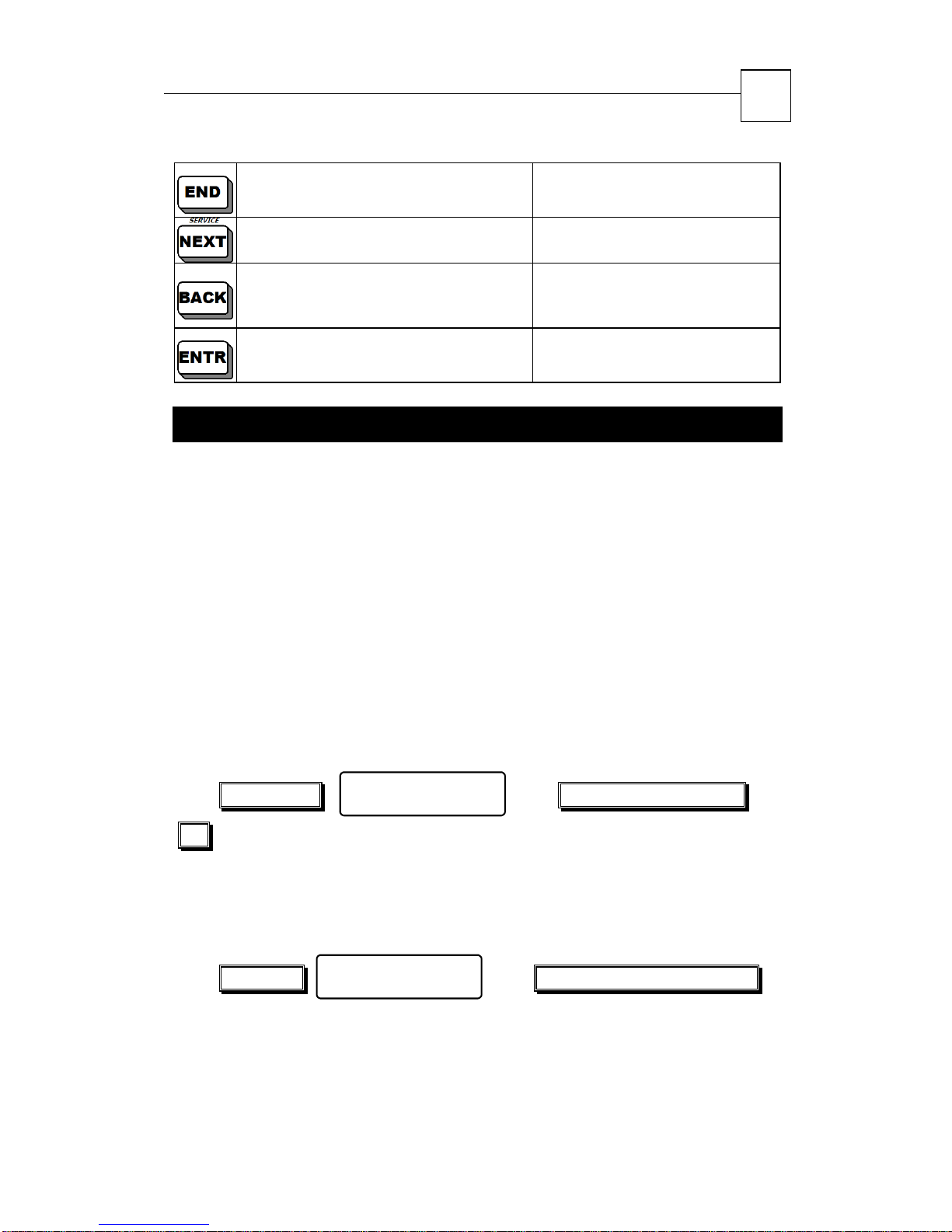
Programming key
-
Programming key Display service Provider
Programming key
Test siren, battery, AC, and tel.
line
Programming key Display system’s name and
information
-
version
2.3 Entering User Menu
In order to program and change data in the user level, you must first
enter the User Menu. User Menu can be fully accessed by the system
administrator (owner) when using the Master Code.
Other users can also access the User Menu but are limited to the
number of available functions according to their authorization level
programmed by the system administrator (owner).
To learn more about authorization levels and how to change them
see “Programming Codes” on page 22
2.3.1 Entering User Menu with Master Code
To access the User Menu:
Master Code
10)
2.3.2 Entering User Menu with User Code
If user is enabled by technician to enter the User Manu:
User Code
User Menu
Choose 1,2...
User Menu
Choose 1,2...
Function key (see page
Function key (see page 10)
If user is not enabled by technician to enter the User Menu (i.e.,
User Code arms/disarms the system), the menu can still be accessed
as follows:
Page 12
12
HUNTER-PRO 32 Intruder Alarm System - Installation Manual
User Code
page 10)
When user selects a function (i.e., the corresponding key is pressed)
that he or she does not authorized to, the system displays the
following:
Access Denied!
Press END
User Menu
Choose 1,2...
Function key
(see
Page 13
HUNTER-PRO 32 Intruder Alarm System - Installation Manual
13
CHAPTER 3:
ARMING &
DISARMING
THE SYSTEM
The system can be armed and disarmed using one of four methods:
Keypad
Remote control or key
Automatically (arming only)
Remotely via telephone
As a rule, the system should be armed ONLY when all zones (but
those on the exit route) are closed and there are no faults (e.g.,
battery, mains, etc.) and/or events (e.g., fire, panic, etc.). It is
possible to arm the system with open zones but these zones should
be bypassed for the system to be armed (see “Arming with Open
Zones” on page 14).
IMPORTANT!
When a zone is bypassed, it will NOT produce an alarm in case an
intruder will be detected at that zone.
The technician should enable the option to auto-bypass open zones
when the system is armed remotely (remote control, key, or via the
phone) or when the system is auto-armed. If not enabled, the
system will not arm with open zones.
IMPORTANT!
When automatic-bypass is enabled, you will have NO indication
when arming the system remotely.
Page 14
HUNTER-PRO 32 Intruder Alarm System - Installation Manual
14
3.1 Arming/Disarming via Keypad
3.1.1 System Messages During Arming
3.1.1.1 Arming with Closed Zones (normal arming)
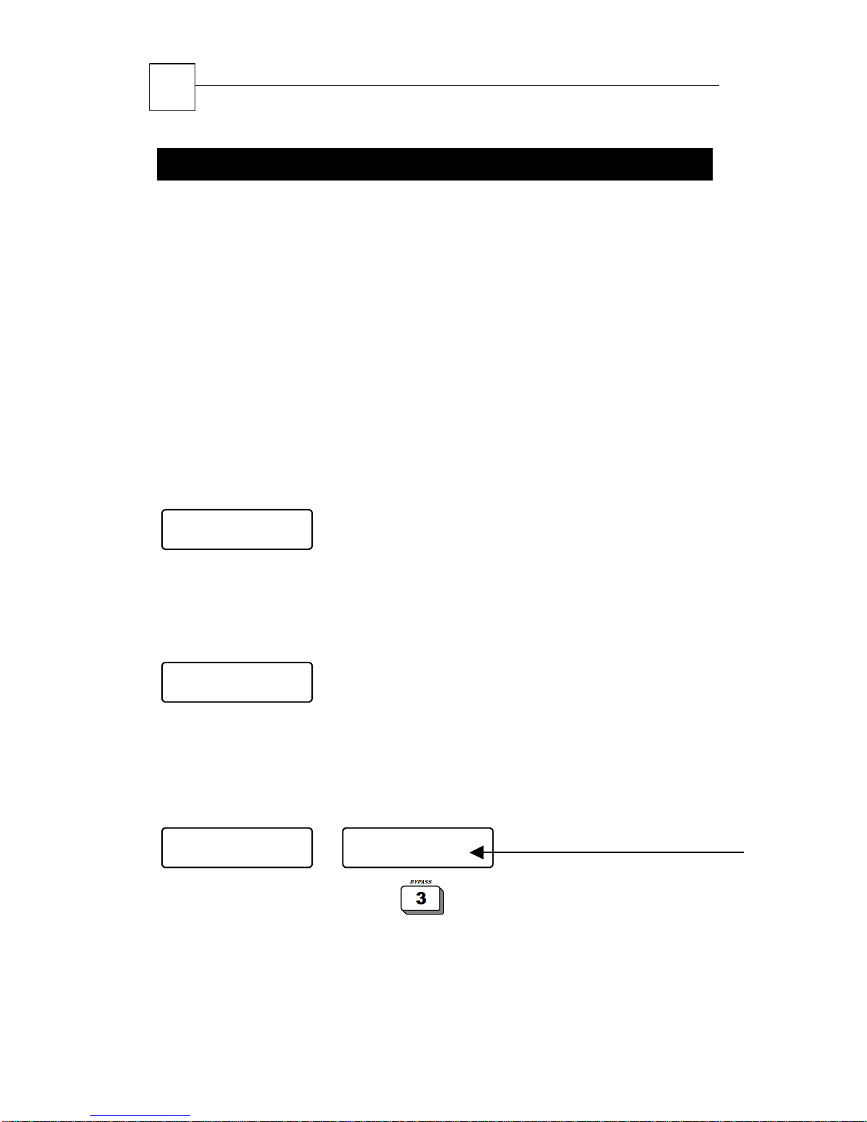
Before arming the system, make sure all zones (except exit delayed
zones – usually zones on exit route) are closed: make sure that in
the keypad display above/below all the LCD zones numbers there is
not a
_ sign blinking or an opened zone indication.
The system can be activated using one of the following codes:
Master Code, User Code, and Short Code.
After entering one of these codes, the green control LED shall begins
to blink, a beep will be heard from the keypad, and the display will
show the exit delay message:
Arming...
Exit Delay 25
At the end of the exit delay, the green control LED shall stop to blink
and stay on, the beep will stop, and the display will show the
following message: “System Set” and then change to the
following display (example):
1 JAN 04 20:05
3.1.1.2 Arming with Open Zone(s)
When activating the system with one or more opened zones (that
are not on the exit route, i.e., exit delayed zones), the keypad will
produce a fast-beep and the display will show:
Open Zone! Press
OP:TOM ROOM
To bypass open zones:
armed
Bypass or END
OP:FRONT DOOR
…
open zones are bypassed & system
Scrolling line: Open Zones & Events
Page 15
HUNTER-PRO 32 Intruder Alarm System - Installation Manual
15
To cancel arming: system returns to normal operation
mode
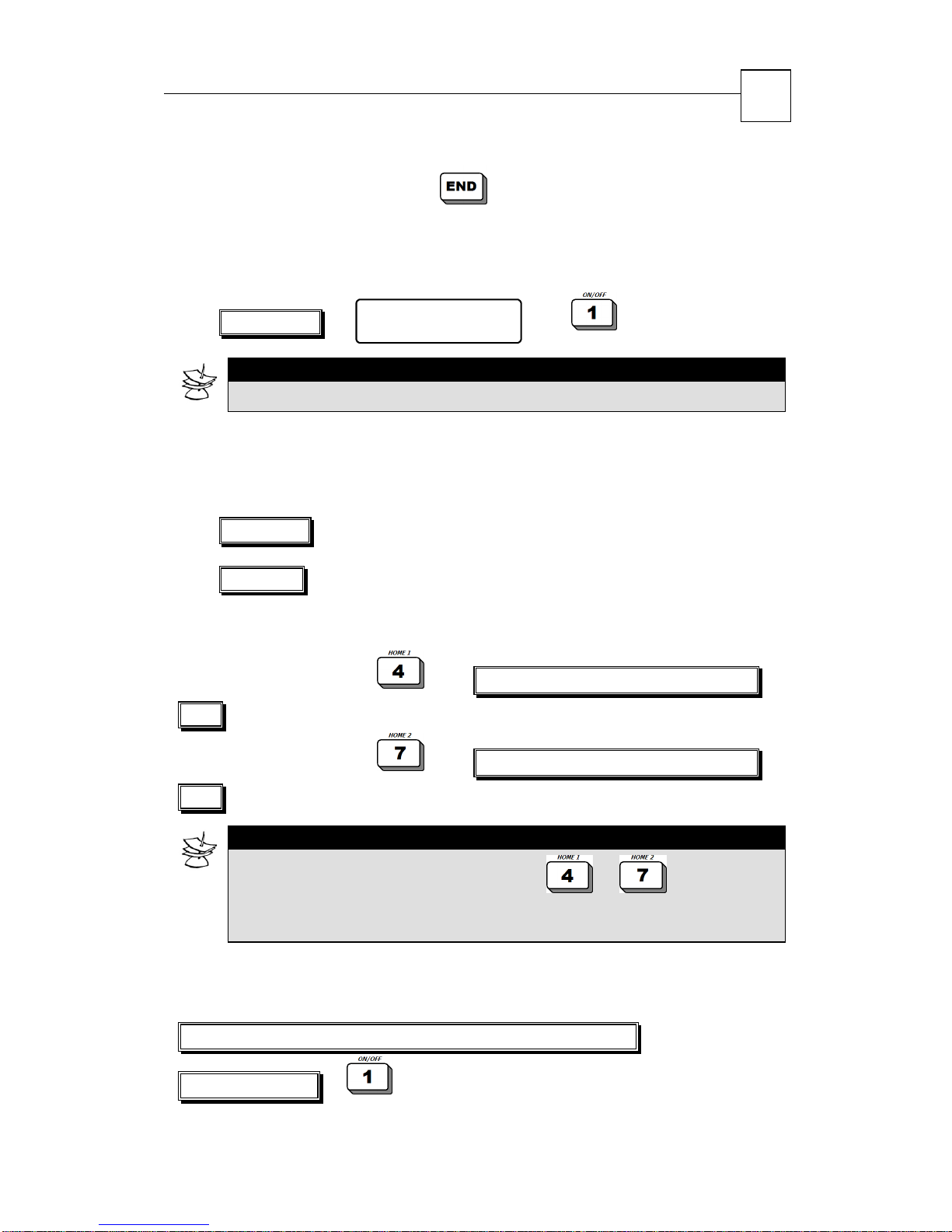
3.1.2 Arming with Master Code
…
Master Code
NOTE:
The system’s default Master Code is: 5555
3.1.3 Fast arming with User Code and/or Short Code
User Menu
Choose 1,2...
Pressing the code shall arm the system immediately:
Short Code
User Code
3.1.4 Arming the System to HOME state
Arming to “HOME 1”:
Code
Arming to “HOME 2”:
Code
NOTE:
After long pressing the HOME key (i.e. or ) and
entering the short/user/master code, the following message is
displayed: HOME 1 or HOME 2 according to the pressed key
Short Code or User Code or Master
Short Code or User Code or Master
3.1.5 Fast Arming
To quickly arm the system, if enabled by technician:
Full Arming:
Page 16
HUNTER-PRO 32 Intruder Alarm System - Installation Manual
16
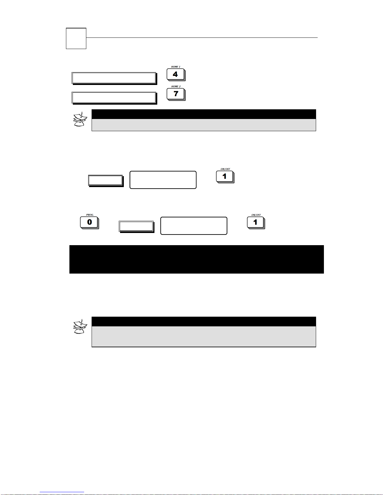
Arming HOME 1:
Arming HOME 2:
NOTE:
Exit delays in HOME 1 and HOME 2 can be disabled by technician.
3.1.6 Arming via the User Menu
If user is enabled by technician to enter the User Manu:
User Code
If user is not enabled by technician to enter the User Menu, it can
still be accessed as follows:
User Code
3.2
Optional feature.
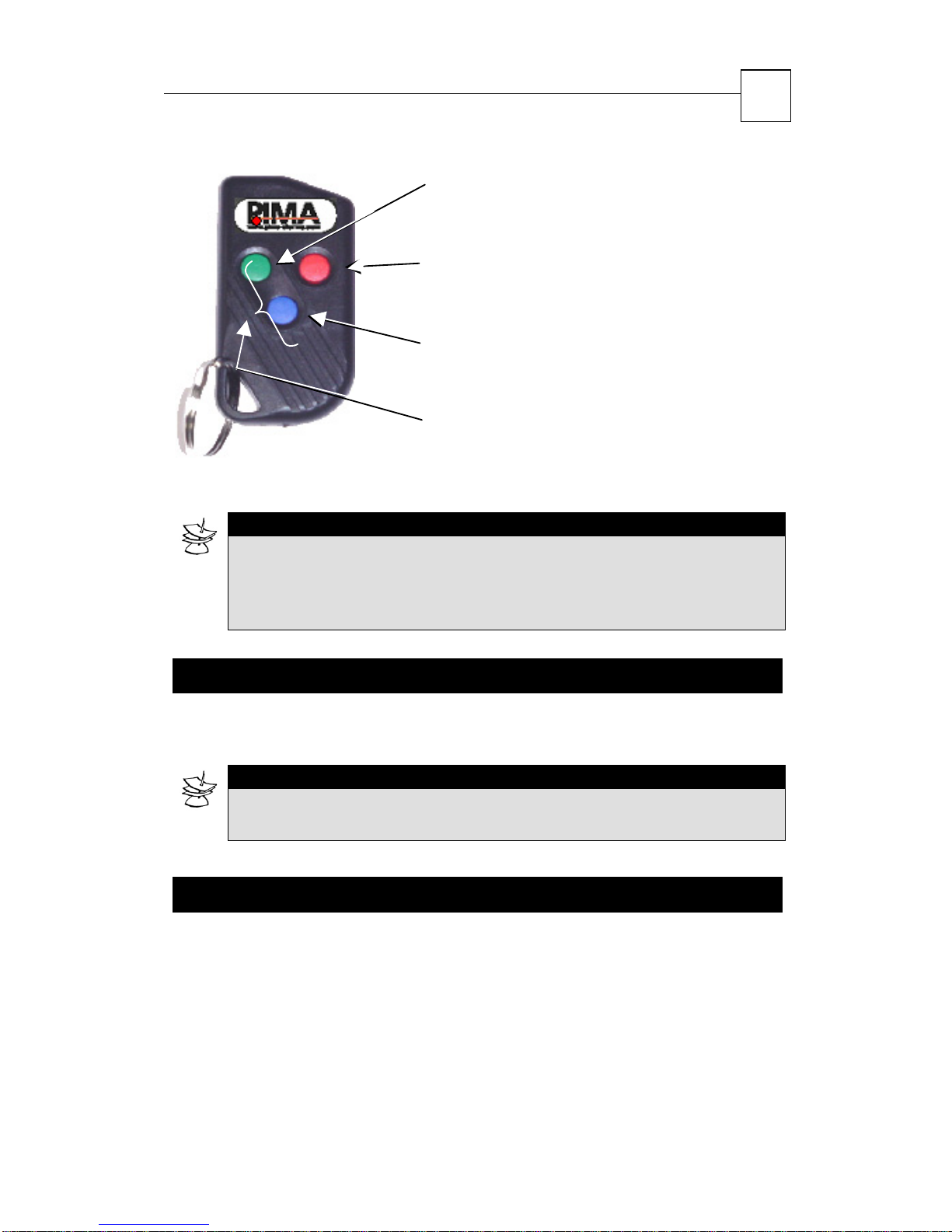
REM-3 remote control has three buttons: arming, disarming, and
HOME 1. Turn to the technician in order to install this feature.
Arming/Disarming with Remote
Control
NOTE:
REM-3 is only available for HUNTER-PRO with wireless add-on
system.
User Menu
Choose 1,2...
User Menu
Choose 1,2...
The remote is a Code-Hopping type (i.e., the code is changed with
each operation and thus prevents “code stealing”) with a key holder
for carrying with ones keys.
Page 17
HUNTER-PRO 32 Intruder Alarm System - Installation Manual
17
ARM:
To arm the alarm system, press the GREEN
button on the remote control.
DISARM:
To disarm the alarm system, press the RED
button on the remote control.
HOME MODE:
To arm the alarm system in a Home Mode,
press the BLUE button.
PANIC:
To send a panic signal to the alarm system,
press the BLUE and GREEN buttons together for
3 seconds.
NOTE:
It is possible for the technician to program the system to produce a
short beep when the system is armed with the remote control.
Doing so, the user can also get indication if the remote control’s
battery is low.
3.3 Arming/Disarming with Key
HUNTER-PRO 32 can be armed/disarmed with a key. Turn to the
technician in order to install this feature.
NOTE:
It is possible for the technician to program the system to produce a
short and beep when the system is armed with the key.
3.4 Automatic Arming
The system can be automatically armed with one of the following
two options: 1. At a preset time; 2. After no-detection period.
At the preset time or after no-detection period, the system will
commence auto-arming unless it was armed before that time. This
feature is valid for all weekdays.
Page 18
HUNTER-PRO 32 Intruder Alarm System - Installation Manual
18
The system can detect movement in the protected area via its
connected detectors and sensors, therefore, it can identify nomovement hence there is no one in the protected area.
When the system starts auto-arming, the display will show
“Automatic Arming” and a 45 seconds ‘warning countdown’ will start,
indicating the arming countdown is to follow. Note that during the
‘warning countdown’ the keypad will beep. During the ‘warning
countdown’, any disarming code can cancel the auto-arming process.
After the ‘warning countdown’ is over, the system will begin regular
arming process, including exit delay and a beep from the keypad.
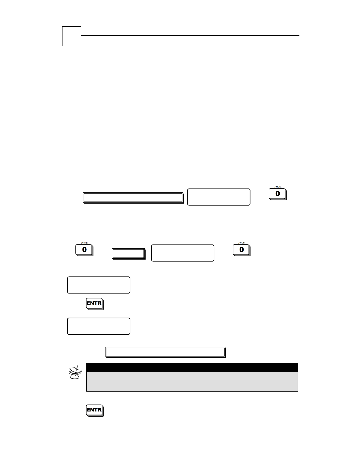
3.4.1 Programming Auto-Arming at Preset time
Master Code /Enabled User Code
-OR-
User Code
The following screen will appear:
Automatic Arming
ENTER/NEXT/END
Press
Automatic Arming
XX:XX
Enter
and move to the next screen:
Time in which the system will be armed
User Menu
Choose 1,2...
User Menu
Choose 1,2...
NOTE:
To cancel Auto-Arming, the Automatic Arming programming needs to be
repeated, and the time to be set as 00:00.
Press to save programming and move to the next screen.
Page 19
HUNTER-PRO 32 Intruder Alarm System - Installation Manual
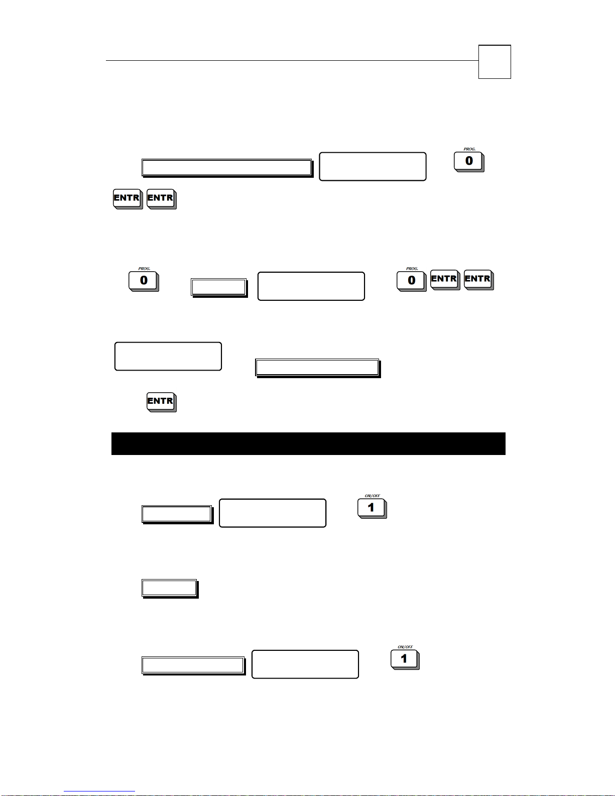
3.4.2 Programming Auto-Arming after no-detection
period
19
Master Code /Enabled User Code
-OR-
User Code
In the following screen, enter the no-detection period (in minutes)
that after which the system commence auto-arming:
Silence Time
X Minutes
Press to save programming and move to the next screen.
Silence Time in minutes
User Menu
Choose 1,2...
User Menu
Choose 1,2...
3.5 Disarming the System
3.5.1 Disarming the System with Master Code
Master Code
3.5.2 Disarming the System with User Code
User Menu
Choose 1,2...
User Code
Entering the code will immediately disarm the system.
-OR-
Enabled User Code
-OR-
User Menu
Choose 1,2...
Page 20
20
HUNTER-PRO 32 Intruder Alarm System - Installation Manual
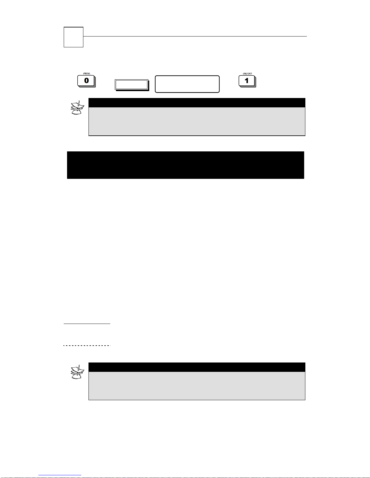
User Code
NOTE:
If the system does not turn to Disarm state, make sure that the time is included
in the preset time frame that enables disarming the system (see section
“Programming User Codes”)
User Menu
Choose 1,2...
3.6 Remote Control via Touch-tone
Phone
The alarm system can be remote-controlled via any touch-tone
telephone, including cellular phone. The system can be controlled
from the moment there is communication between the system and
the telephone, whether the system called the telephone, or when
initiated by the user as following described:
1. Dial the telephone number the system is connected to
2. Wait for the system’s confirmation tone (a long tone followed
with two beeps)
3. Enter Master Code (note NOT to enter the code before the end
of the confirmation tone)
4. Wait a few seconds until the alarm system confirms its status,
using one of the two following tones:
Continuous tone:
beep System armed
NOTE:
The system will not identify commands from the telephone while sounding the
confirmation tone. It is important to wait until to confirmation tone is over
before pressing the telephone keys that control the system.
5. Execute command by pressing a key on the phone.
The following table includes system’s commands by phone keys:
System disarmed
Page 21
HUNTER-PRO 32 Intruder Alarm System - Installation Manual
Phone key: Function:
1 Arm the system
2 Disarm the system
4 Arm the system in “Home 1” mode
5 Switch on the Relay
6 Switch off the Relay
7 Arm the system in “Home 2” mode
8 Listen in (only available with a MIC-100)
0 Disables siren and dialer (in case of an alarm).
NOTE:
The alarm system confirms the command was received by two
short beeps.
21
While the system and the telephone are communicating, the
following message will display on all connected keypads:
“Other keypad in use”.
If the system does not receive any command for a period of 60
seconds, it shall disconnect and return regular operation mode. The
system will remain in standby (with the above displayed on keypads)
for another 60 seconds before keypad operation returns.
Page 22
22
HUNTER-PRO 32 Intruder Alarm System - Installation Manual
CHAPTER 4:
PROGRAMMIN
G AND
OPERATION
4.1 Programming Codes
A code is a combination of numbers that allows programming,
arming, disarming the system and more. During the programming
process, the keypad’s display will show the name of the code you
want to program. At any stage of the programming, it is possible to
return to the main menu by pressing the
IMPORTANT!
Pay attention that HUNTER-PRO 32 has a code-control feature that
does not allow entering identical codes. For example, if one of the
user (or master) codes is programmed as 1010, any attempt to
program a new code as 1010 or starting with 1111 (e.g., 10101,
10102, 10103, etc.) will display an error message.
4.1.1 Programming Master Code
The default Master Code is: 5555.
The Master Code can ONLY be changed with the master code.
key.
The Master Code is used for accessing memory and programming
different function as described further. It is also possible to arm and
disarm the system with the Master Code.
IMPORTANT!
Pay attention that the code need to be between 4 and 6 digits:
Page 23
HUNTER-PRO 32 Intruder Alarm System - Installation Manual
23
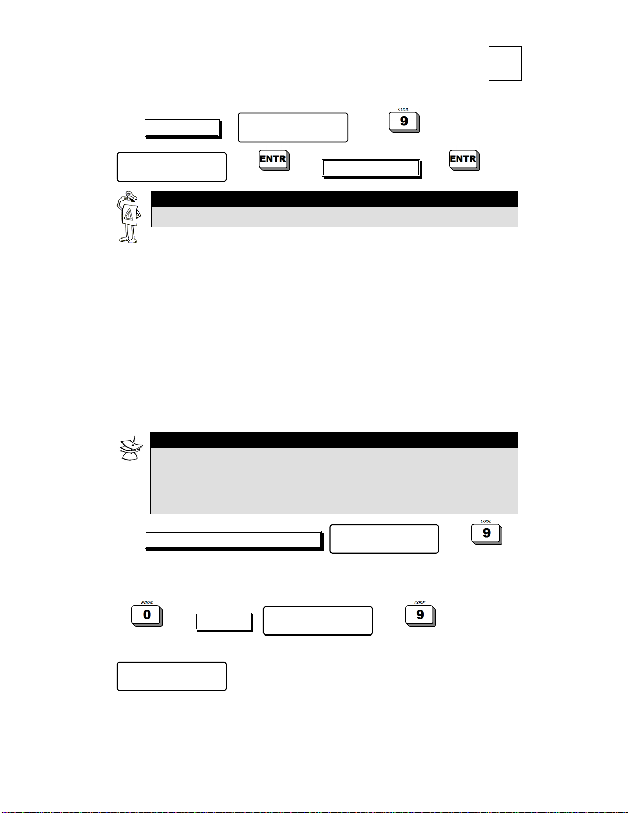
Master Code …
Master Code
ENTER/NEXT/END
IMPORTANT!
For better protection, change the default code after installation.
User Menu
Choose 1,2...
New Master Code
4.1.2 Programming Users
The User Codes are mainly for arming and disarming, but depending
on the user’s authorization level, the user can also go into the User
Menu and perform various tasks as viewing memory changing other
users settings, program telephone numbers, etc.
HUNTER-PRO 32 holds up to 24 different User Codes, 4 to 6 digits
each.
See “Entering User Menu” on page 11 for a description on how to
access the User Menu with User Code.
NOTE:
A name can be programmed for each user, a time frame in which
he will be active, allocation to one partition or more as well as
limiting authorizations.
User Code is a number of 4 to 6 digits.
Master Code /Enabled User Code
-OR-
User Code
The following screen will appear:
Master Code
ENTER/NEXT/END
(Master Code)
User Menu
Choose 1,2...
User Menu
Choose 1,2...
Page 24
HUNTER-PRO 32 Intruder Alarm System - Installation Manual
24
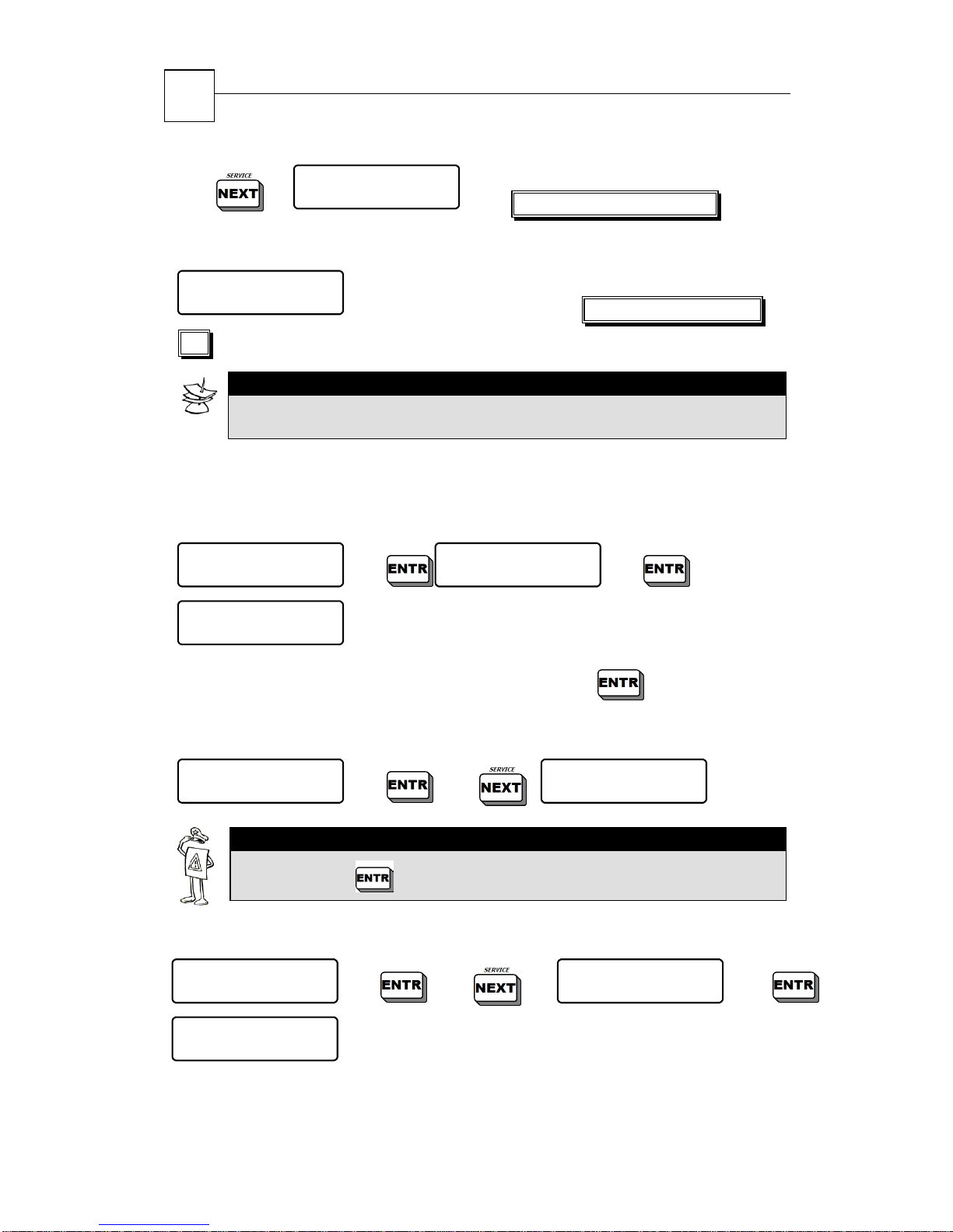
User 1 *
…
-OR-
User 1 *
ENTER/NEXT/END
24)
NOTE:
An asterisk (*) placed to the right of the user’s name means that the
user is already defined in the system.
Following are the different options with user programming
ENTER/NEXT/END
(Enabled User Code) Enter user number (1-
Enter user number (1-24)
4.1.2.1 Changing (adding new) User Code
User 1
ENTER/NEXT/END
User 1
****** (4-6)
Enter a new User Code (4 to 6 digits) and press
Enter/Change Code
ENTER/NEXT/END
to save.
4.1.2.2 Deleting User
User 1
ENTER/NEXT/END
IMPORTANT!
After pressing , all user settings will be deleted!
Delete Code
ENTER/NEXT/END
4.1.2.3 Entering User Name
User 1
ENTER/NEXT/END
User Name 1
User 1
You are now ready to enter text.
X2
User Name
ENTER/NEXT/END
Page 25
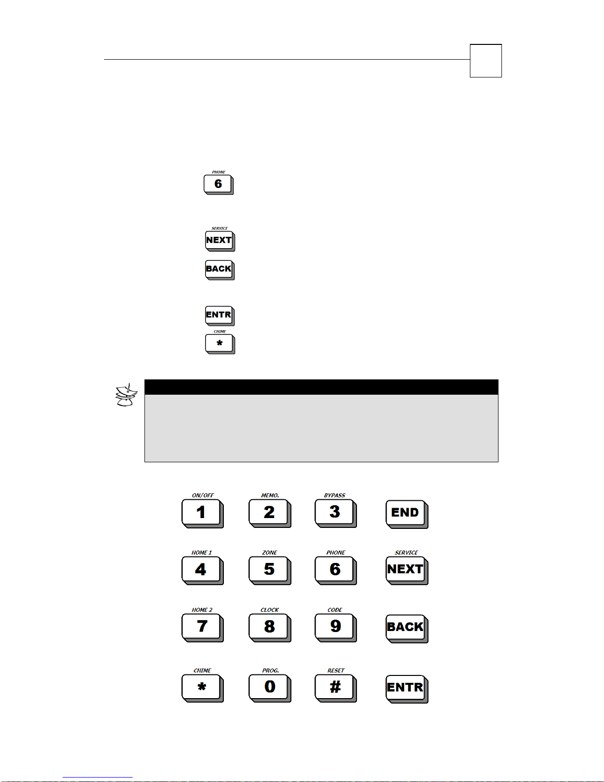
HUNTER-PRO 32 Intruder Alarm System - Installation Manual
How to Select and Enter Characters?
Each numeric code-entry key has characters associated with it the
same as with standard cell phone letters. The number of key
depressions you make determines which character is selected, e.g.
25
the numeric key
represents ‘MNO6’. To select ‘M’, press the
key once; to select ‘O’, press the key three times. See bellow for all
keys and their associated characters.
Pressing the
Pressing the
key: moves the cursor forward one character
key: moves the cursor backwards one
character
Pressing the
Pressing the
key: saves the data
key deletes a character (number/letter) as
well as a whole user name.
NOTE:
User Name includes up to 8 characters (letters or digits)
Each arming/disarming will enter the memory along with the user
name, date and time (see section “Memory Display” on page 36)
The order of the ABC letters is identical to that in a cellular phone
. , ? ! 1 A B C 2 D E F 3
Cancel
G H I 4 J K L 5 M N O 6
P Q R S 7 T U V 8 W X Y Z 9
( ) / * : - + #
Next char.
Prev. char.
0
Save
Page 26
HUNTER-PRO 32 Intruder Alarm System - Installation Manual
26
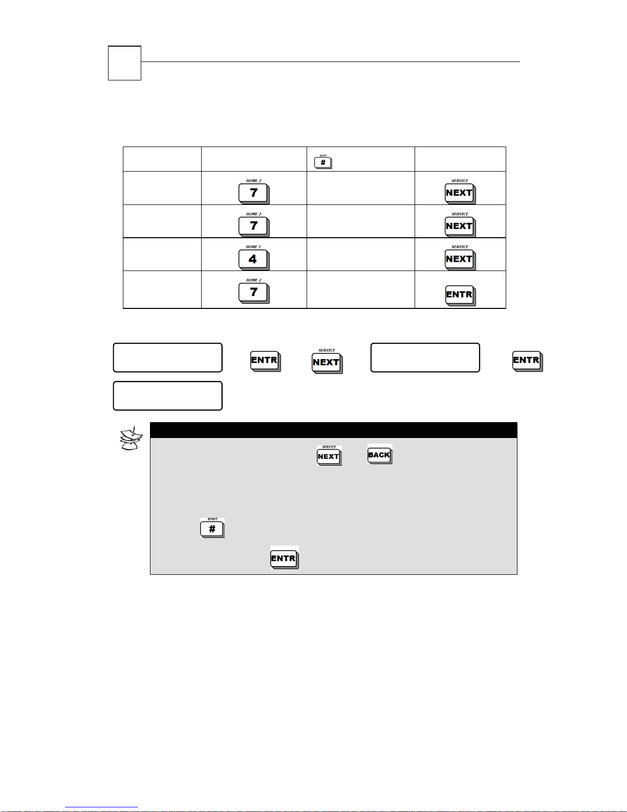
The following example illustrates key depressions for the word
‘7PIR’.
Character Key Pressed
7
P
I
R
Depressions
4.1.2.4 Modifying User Access
User 1
ENTER/NEXT/END
UTCMBKA
+++-----
NOTE:
X3
(code programming bar)
To scroll on Access Bar, use and keys.
5
1
3
3
User Access
ENTER/NEXT/END
Follow Key
Marking a “+” under a parameter’s letter authorizes the user to
program this parameter. Marking a “-“ denies this possibility.
In order to change the mark from “-“ to “+” (and vise versa)
press
To save data press
User Access Bar (parameter letters)
U + User can program User Codes; (default)
- User Code programming is disabled
T + User can program phone numbers; (default)
- Phone numbers programming is disabled
C + User can program time and date; (default)
- Time and date programming is disabled
Page 27
HUNTER-PRO 32 Intruder Alarm System - Installation Manual
M + User can view the Memory Log;
- User cannot view Memory Log (default)
B + User can bypass zones;
- User cannot bypass zones (default)
K + User can operate partition via any keypad (when using
partitions);
- User can operate partition ONLY via designated keypad
(default)
A + User can program auto-arming parameter;
- User cannot program auto-arming (default)
4.1.2.5 Programming User’s Disarming Window
27
User 1
ENTER/NEXT/END
User 1
00:00 To 23:59
X4
Disarm Window
ENTER/NEXT/END
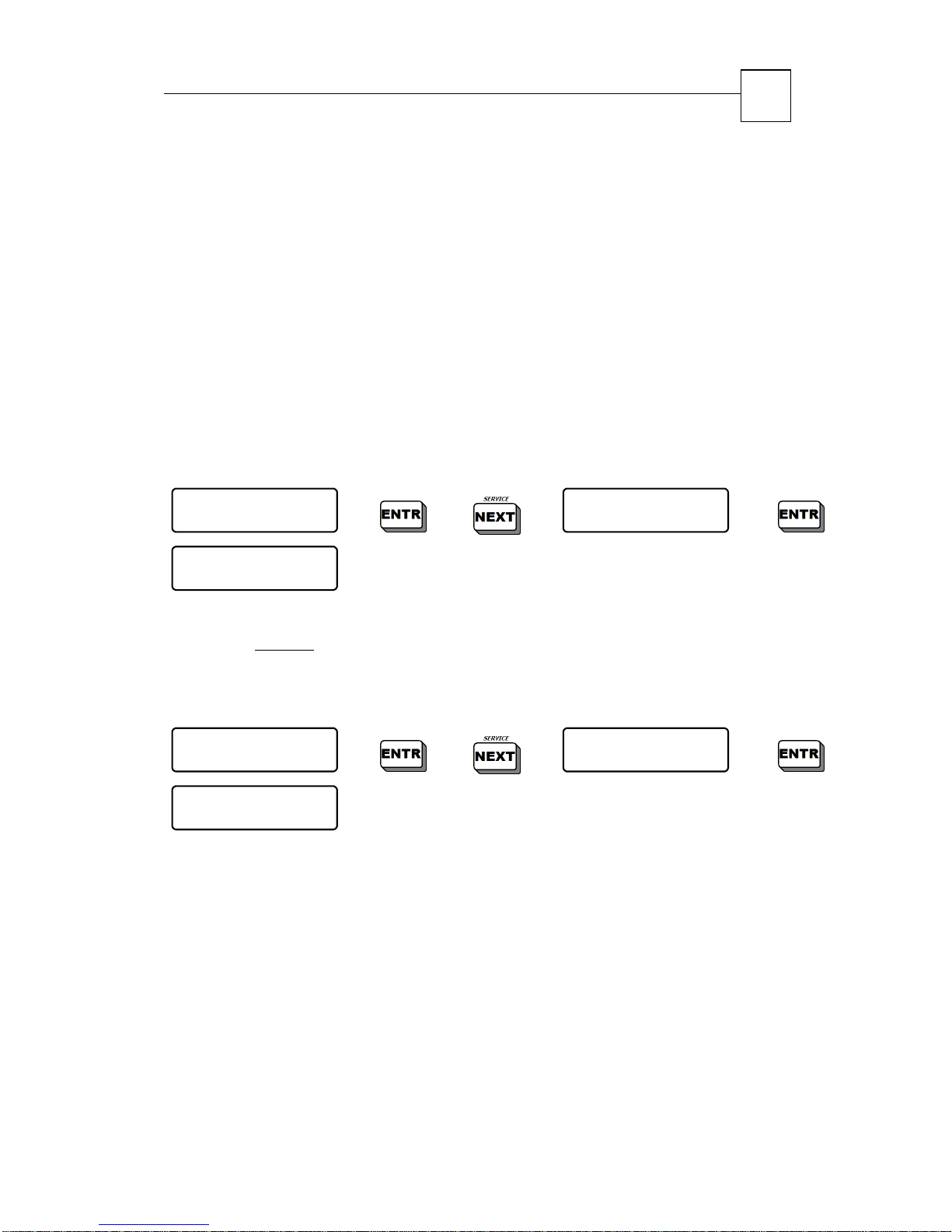
This feature sets the time frame (start and end time) in which the
user can disarm
the system. By default, the user time is not limited
(i.e., start: 00:00; end: 23:59).
4.1.2.6 Programming User Partitions
User 1
ENTER/NEXT/END
Part. For User1
+++++++---------
X5
This feature links a user to a partition(s). When creating
subsystems, there is also a keypad linked to each split (done by the
technician), therefore the user can only arm/disarm and view the
linked partition using the designated keypad. When a user is
required to control partitions using any keypad, the option “K” on the
authorization bar should be set to ‘+’.
Partitioning
ENTER/NEXT/END
With standard system installation, i.e. no partitions, all users are
assigned by default to all partitions.
Page 28
HUNTER-PRO 32 Intruder Alarm System - Installation Manual
28
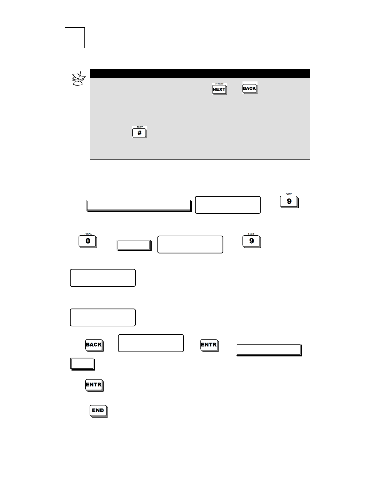
NOTE:
To scroll on User Partitions Bar use and keys.
Marking a “+” above a partition allocates it to the user. Marking a
“-“ denies this possibility.
In order to change the mark from “-” to “+” (and vise versa)
press the key.
There is no limitation in the number of partitions allocated to a
user.
4.1.3 Programming Short Code
This two-digit code is only used to arm the system.
Master Code /Enabled User Code
-OR-
User Code
The following screen will appear:
Master Code
ENTER/NEXT/END
-OR-
User 1 *
ENTER/NEXT/END
X2
digits)
(when using Master Code)
(when using Enabled User Code)
Short C ode
ENTER/NEXT/END
User Menu
Choose 1,2...
Enter new code (2
User Menu
Choose 1,2...
to save
Press
a number of times unit exiting to time/zone screen
Page 29
HUNTER-PRO 32 Intruder Alarm System - Installation Manual
29
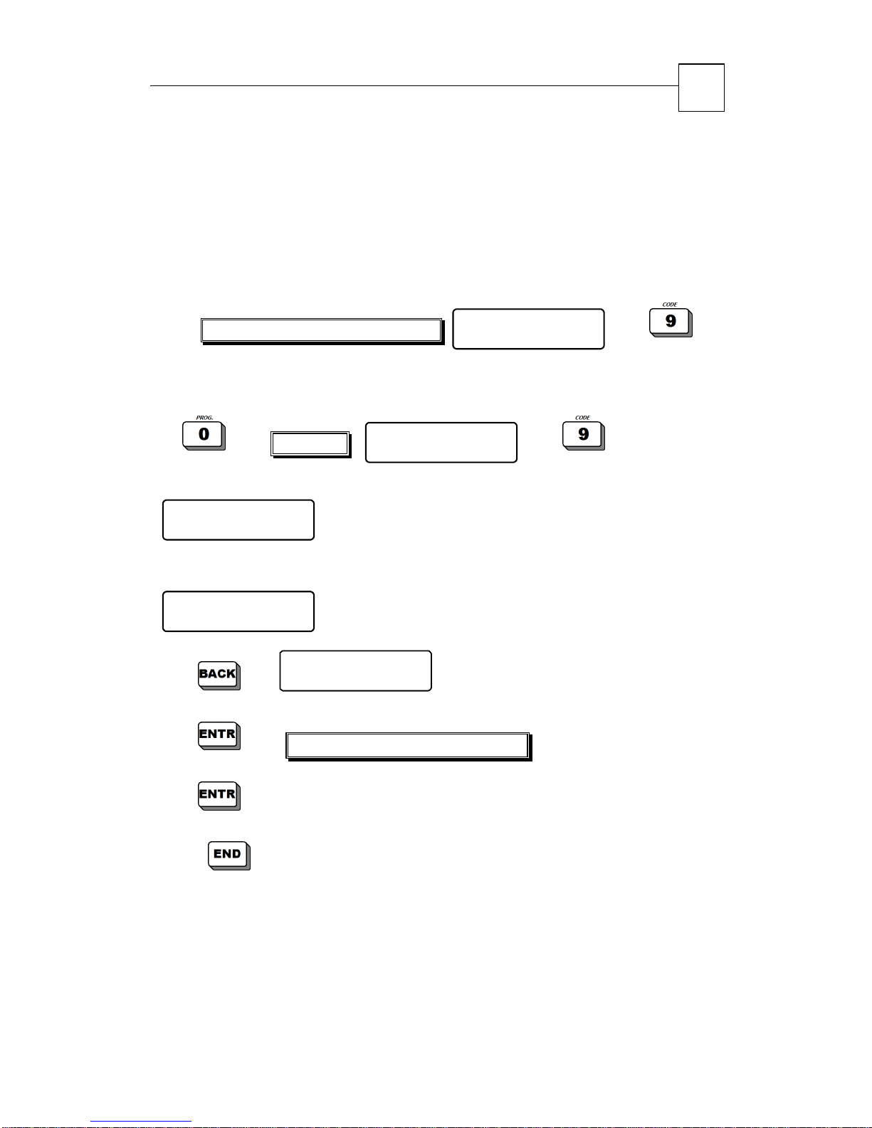
4.1.4 Programming Duress Code
This code is useful when the system is connected to a security
station. The Duress code will disarm the system (if armed) and
trigger the Silent Alarm, sending a duress signal to the security
station without activating the sirens. Note the code is between 4 to 6
digits:
Master Code /Enabled User Code
-OR-
User Code
The following screen will appear:
Master Code
ENTER/NEXT/END
-OR-
User 1 *
ENTER/NEXT/END
X3
(when using Master Code)
(when using Enabled User Code)
Duress Code
ENTER/NEXT/END
User Menu
Choose 1,2...
User Menu
Choose 1,2...
Enter new code (4 to 6 digits)
to save
Press
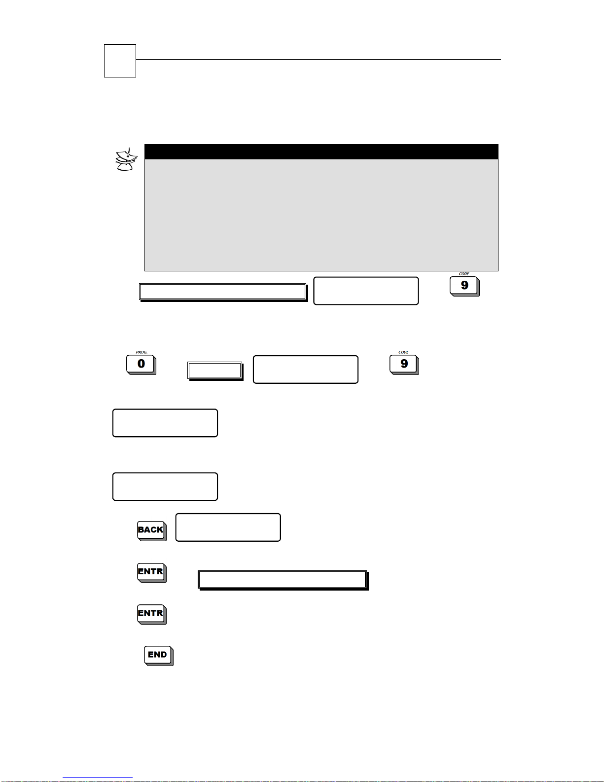
4.1.5 Programming Door Code
Arms and disarms a system’s relay. Useful for opening and closing
electric gates, activating video cameras, and more. The code can be
a number of times unit exiting to time/zone screen
Page 30
HUNTER-PRO 32 Intruder Alarm System - Installation Manual
30
used manually (directly pressed on keypad) and remotely via
telephone (see section
NOTE:
Each entering of a Relay Code changes the relay’s status (ON to
OFF and vise versa).
When the relay is ON, the letter “R” appears on the display, left
to the time.
The relay is activated for a preset time programmed by the
technician.
The Code is between 4 to 6 digits.
3.6 “Remote Controlling via Telephone”).
Master Code /Enabled User Code
-OR-
User Code
The following screen will appear:
User Menu
Choose 1,2...
User Menu
Choose 1,2...
Master Code
ENTER/NEXT/END
-OR-
User 1 *
ENTER/NEXT/END
Relay Code
ENTER/NEXT/END
(when using Master Code)
(when using Enabled User Code)
Enter new code (4 to 6 digits)
to save new relay code
Press
a number of times unit exiting to time/zone screen
Page 31
HUNTER-PRO 32 Intruder Alarm System - Installation Manual
31
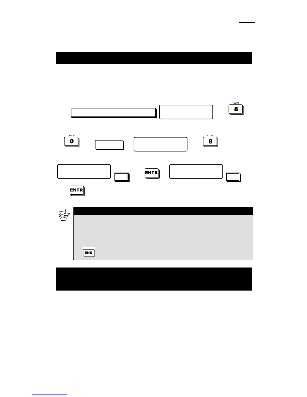
4.2 Programming Time and Date
Time and date are constantly displayed on screen, used for the User
Code’s time frames and are included in the system’s memory log.
It is crucial that the time and date remain accurate, especially for the
memory log, which is crucial for the technician visits.
Master Code /Enabled User Code
-OR-
…
User Code
The following screen will appear:
Hour
00:00
Time …
User Menu
Choose 1,2...
NOTE:
Enter time in 24:00 (HH:MM) format and date in day/month/year
format
The system will not accept meaningless data, such as 25:25 time.
In such a case a fault message will appear. To correct, press the
User Menu
Choose 1,2...
Day Month Year
01 01 04
Date
key and enter time again.
4.3 Private Dialer Telephone
Numbers
HUNTER-PRO 32 system has four private dialer telephone numbers.
The dialer will dial each phone number in two sets (i.e. total of 8
attempts) and trigger an alarm warning sound, when the call is
‘picked’. After the warning sound is over, the system awaits for
remote-controlled commands that can be transmitted via the
telephone used by the system. The system shall hang-up after a
Page 32
HUNTER-PRO 32 Intruder Alarm System - Installation Manual
32
minute of not receiving any command (see “
Touch-tone Phone
NOTE:
In case a Voice-Unit is connected to the system, once the
call is picked-up, there is a recorded message, and not a
warning sound.
The dialer aborts the dialing attempts in the following cases:
The system’s status changes from ON to OFF
A “Stop Siren/Dialer” command was received via telephone. The
first Private Dialer User that gives an ‘abort’ command causes
the other Private Dialer Users in the phone list will not receive
the system’s report.
” on page 20).
Remote Control via
All Private Dialer Telephone Numbers were dialed to twice
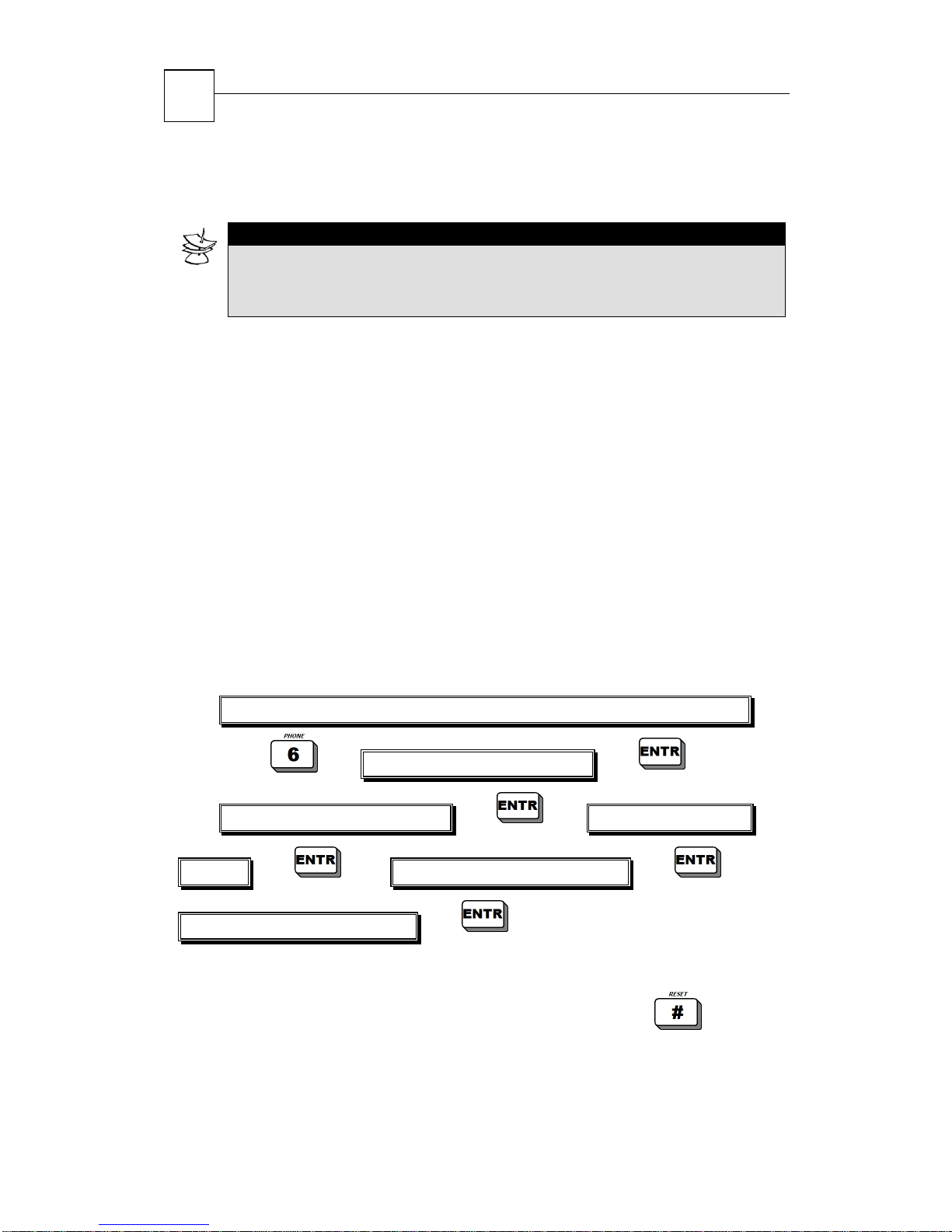
4.3.1 Programming Telephones
It is possible to combine the process of Entering/Deleting/Changing
programmed telephone numbers once in the Telephone Menu.
4.3.1.1 Programming User’s Authorizations
Master Code/Enabled User Code/Zero long press+User Code
Enter 1 telephone number
Enter 2 telephone number Enter 2 telephone
number Enter 3 telephone number
Enter 3 telephone number
4.1.1.1 Deleting a Programmed Telephone Number
To delete a programmed telephone number, press the
instead of the telephone number.
key
Page 33
HUNTER-PRO 32 Intruder Alarm System - Installation Manual
33
4.4 Chime
Programming the “Chime” feature enables to control opening/closing
doors and windows by activating the keypad’s buzzer for two
seconds each time a door/window is opened. This feature is
especially useful when there are small children in the house, or in
shops.
NOTE:
The “Chime” feature is only enables when system is disarmed.
4.4.1 Programming Chime Zone
Master Code/Enabled User Code/Zero long press+User Code
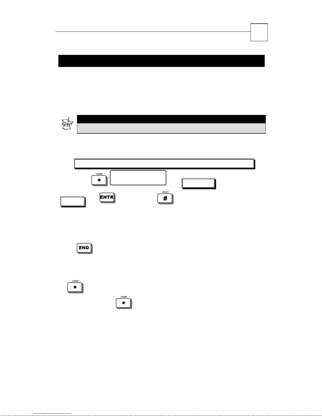
Enter zone no: 1
number to confirm or to release.
On the display the letter “C” shall appear above/below the zone
programmed to trigger the chime, and the screen will move to the
next zone.
Press
4.4.2 Temporary Cancellation of Chime
Temporary cancellation of chime is valid for all zones:
a number of times unit exiting to time/zone screen
Rel.-# Con.-ENTR
Enter zone
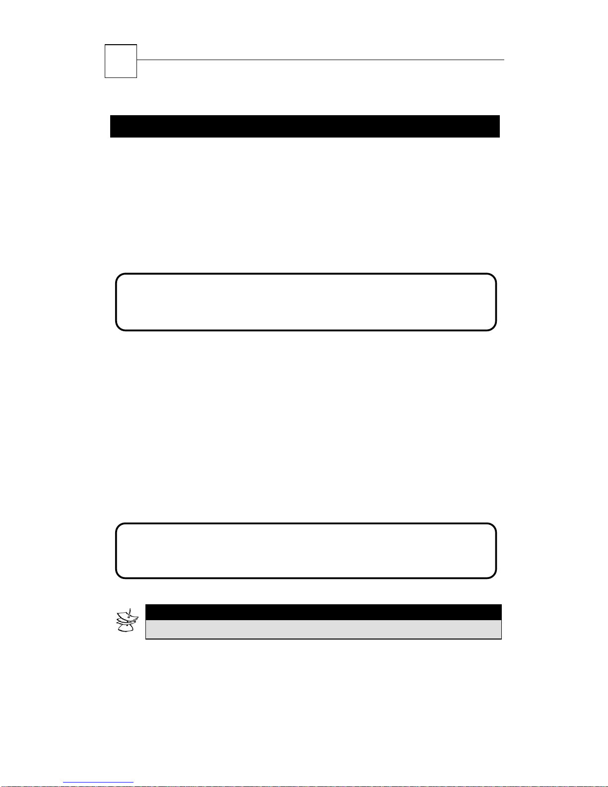
Press and hold the
according to the state in which the system is in; the display will show
one of the following messages:
key to enable/disable the chime feature
Chime Active Chime Disables
Page 34
17 18 19 20
21
22 23 24 25 26 27 28 29 30 31 32
_
17 18 19 20
21
22 23 24 25 26 27 28 29 30 31 32
HUNTER-PRO 32 Intruder Alarm System - Installation Manual
34
4.5 Alarm
There are two possibilities for displaying the name and number of
the zone/s that triggers the alarm at the time of an alarm. The
technician sets the default display.
PIMA Display
All the zones and their status appear simultaneously in a single
screen (see section 2.2 “PIMA Display”). Example:
-- B - - _-A-F------
-- - - B ---
1 2 3 4 5 6 7 8 9 10 11 12 13 14 15 16
Scrolling Display
The name and number of the zone/s that triggered the alarm will
appear separately, each in a different screen, in an automatic
successive manner. The display will repeat itself for a few minutes,
until it will return to the regular screen of an activated system.
In addition, the system will commence other actions according to the
zones’ programmed features at time of alarm, such as dialing private
telephone numbers, disabling siren (“silent alarm”), dialing
monitoring station and more. Example:
4
OP :
1 2 3 4 5 6 7 8 9 10 11 12 13 14 15 16
S E P 0 4 2 1 : 2 2
-S--S--
ZONE 7
NOTE:
The zone names are programmed only by the technician.
Page 35
HUNTER-PRO 32 Intruder Alarm System - Installation Manual
35
4.6 Panic
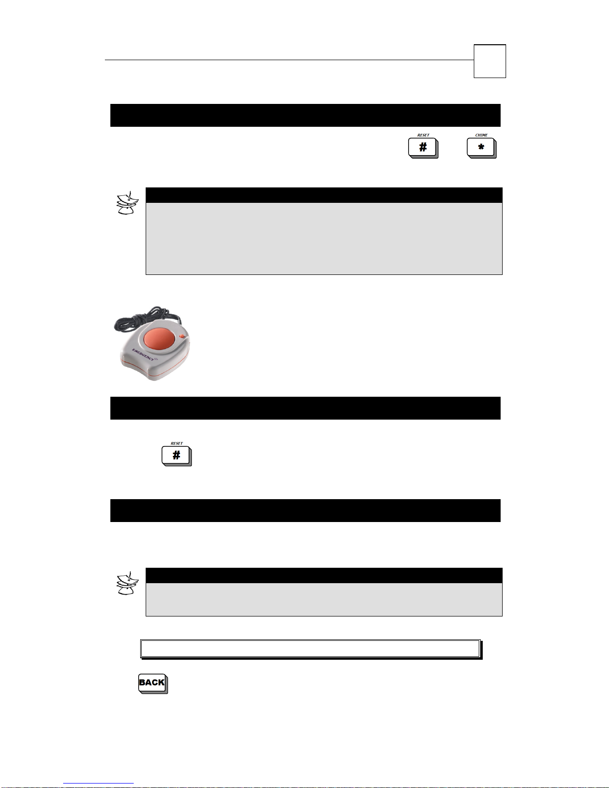
To activate panic, press and hold simultaneously the and
keys for two seconds.
NOTE:
You can customize your system's response to a panic event, for
example, calling the Monitoring Station or your private telephone
number, activate a relay (video camera), activate siren, etc.
Consult your installer about programming the appropriate Panic
Response for your needs.
4.6.1 Panic Button
(Optional feature) Pressing the button triggers
sirens and send a panic signal to monitoring station
and/or dial to private telephone number (according
to technician programming).
4.7 Smoke and Fire Detectors Alarm
In case an alarm is triggered due to smoke/fire detectors, press and
hold the
release the detector.
key (until a confirmation sound) in order to reset and
4.8 System Tests
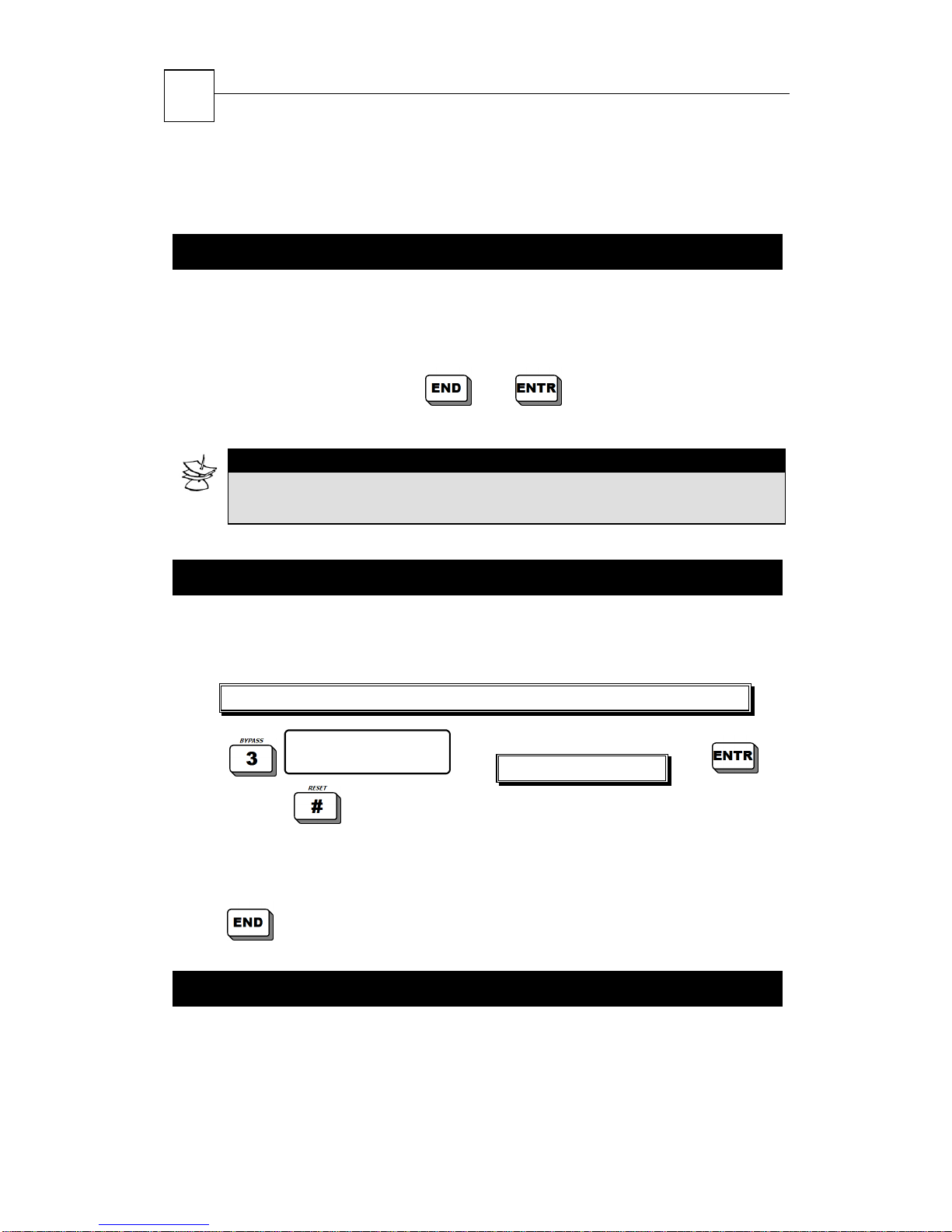
This feature tests that the back-up battery, siren and telephone line
are in order.
NOTE:
The battery’s status can be tested only when the system is
connected to mains power source.
Master Code/Enabled User Code/Zero long press+User Code
Page 36
HUNTER-PRO 32 Intruder Alarm System - Installation Manual
36
Follow the test process displayed on the screen in case fault
messages appear.
4.9 Canceling Keypad Buzzer
The keypad produces a variety of sounds at times of pressing a key,
confirming a long-press, during countdown, disarming the system,
and so on.
Simultaneously pressing the
this feature.
NOTE:
When the buzzer is cancelled no sounds will be produced from the
keypad.
and keys activates/cancels
4.10 Bypassing Zones
This feature is used for temporary bypassing of zone/s, for example
in case of a fault.
Master Code/Enabled User Code/Zero long press+User Code
Zone number: 1
to confirm or to release.
In PIMA Display, the letter “B” will appear above/below the bypassed
zone/s, and display will continue to the next screen.
Entr-Conf #-Rst
Enter zone number
Press
a number of times unit exiting to time/zone screen
4.11 Memory Log
The system memorizes up to past 410 events and operations in a
chronological order.
Page 37
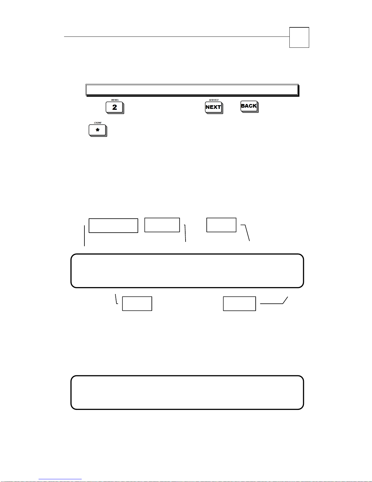
17 18 19 20
21
22 23 24 25 26 27 28 29 30 31 32
17 18 19 20
21
22 23 24 25 26 27 28 29 30 31 32
HUNTER-PRO 32 Intruder Alarm System - Installation Manual
37
4.11.1 Accessing Memory Log Manually
Master Code/Enabled User Code/Zero long press + User Code
scroll events using and .
Press
to jump 10 events in one key-press.
4.11.2 Memory Log Display
Arming and disarming are memorized with the name if the code that
initiated them, along with any bypassed zones present at the time.
The list of the bypassed zones is presented before those of the
arming. Automatic armings are also memorized.
Example 1:
Event number
2 )1 S E P 04 21:20
4 ALAR M
1 2 3 4 5 6 7 8 9 10 11 12 13 14 15 16
Event
Note that at a time of an alarm, in addition to the screen above,
automatically appears another screen with the zone’s name (e.g. in
this example, the following screen will show “Front Door”.
Example 2:
4 )4 S EP 04 21:22
E x p ander Fault 1
1 2 3 4 5 6 7 8 9 10 11 12 13 14 15 16
Example 3:
Page 38
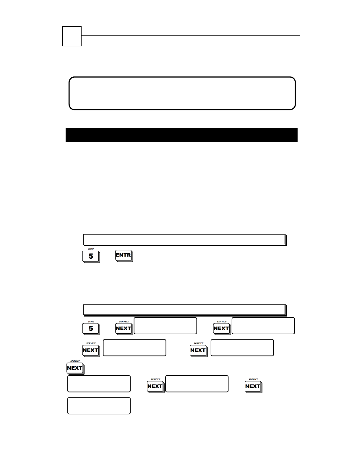
17 18 19 20
21
22 23 24 25 26 27 28 29 30 31 32
38
HUNTER-PRO 32 Intruder Alarm System - Installation Manual
7 )4 S EP 04 21:42
A C Fault
1 2 3 4 5 6 7 8 9 10 11 12 13 14 15 16
4.12 System Display Types
HUNTER-PRO 32 has two possible system displays:
PIMA Display: All the zones and their status appear in a single
screen
Scrolling Display: A detailed description of the zones and their
status, each zone in a different screen, and automatically
appearing one after the other.
In order to choose display type:
Master Code/Enabled User Code/Zero long press+User Code
display changes from PIMA Display to Scrolling
Display (and vise versa).
4.12.1 Zone Status Display
Master Code/Enabled User Code/Zero long press+User Code
Display Type:
Display Type:
Soak Test Zones
Display Type:
Activated Partition
Opened Zones
Display Type:
Fast Zone Display
Display Type:
Chime Zones
Display Type:
Bypassed Zones
Display Type:
Zone List
Page 39
HUNTER-PRO 32 Intruder Alarm System - Installation Manual
39
IMPORTANT!
Pressing in "Zone List”/”Opened Zones”/”Bypassed
Zones”/”Soak Test Zones”/”Chime Zones” screens gives a
detailed description of the zones in this category.
Pressing in "Activated Partitions" screen gives the
detailed description on the zones in this category in the following
manner:
Partitions marked by an “X”: Activated
Partitions marked by an “-“ : Not Activated
In order to scroll between zones in the same category, use the
and keys.
Page 40
40
HUNTER-PRO 32 Intruder Alarm System - Installation Manual
CHAPTER 5:
TROUBLESHOOTIN
G
NOTE:
If more then one failure is detected, the display will scroll the
failure list one after the other . If mor e than one keypad is
connected to the HUNTER-PRO, and you are programming
the system from one keypad, then the display on all other
keypad will display:
will also be displayed whenever the installer uses a modem in order
to program the HUNTER-PRO, or when someone is in control of the
HUNTER-PRO
via telephone.
Other Keypad in Use
This
The following table describes the possible Alarm System Faults:
Displayed
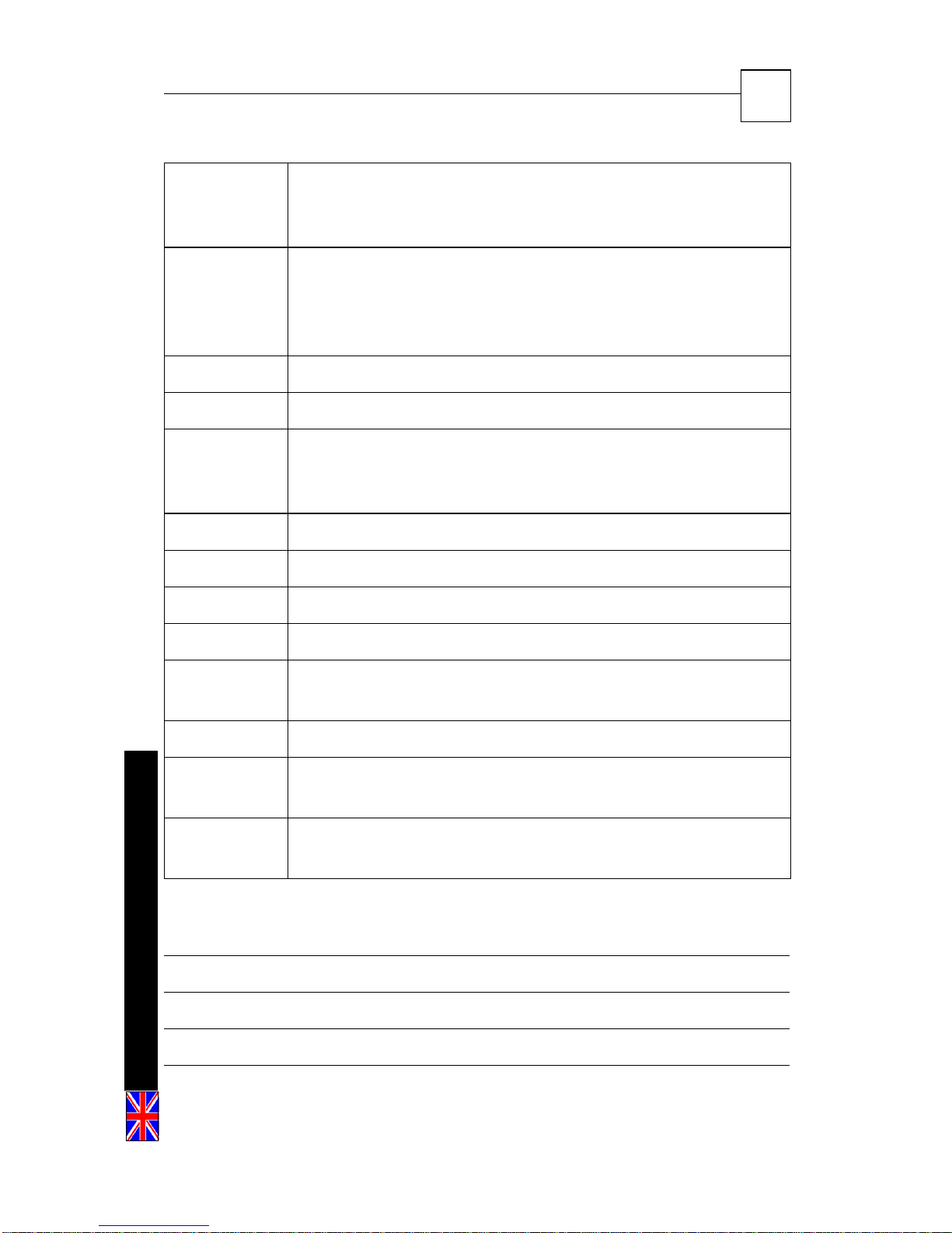
Fault
Battery Wait approximately 24 hours for the indication to
Wireless
Receiver
AC voltage Usually appears during a power failure. If other electrical
What can I do?
disappear. If the fault indication persists longer then one
day, the back-up battery should be replaced.
A wireless receiver failure can be the cause of
communication failure between the detector and
receiver.
appliances in the house are operating, check the switch
or fuse to which the alarm system is connected. If the
cause of the fault is unclear, call the installer.
Page 41
HUNTER-PRO 32 Intruder Alarm System - Installation Manual
41
Clock Appears following a prolonged power failure during which
the backup battery was completely discharged. Set time
and date (see section 3.8.4)
Phone Perform “system self-test” (see section 3.6). Verify during
the test that other instruments connected to the Alarm
System’s telephone line (i.e., telephone sets, facsimiles,
etc.) are not active. If the fault persists, call the installer.
Tamper 1 Tamper switch 1 is open. Call the installer.
Tamper 2 Tamper switch 2 is open. Call the installer.
Low pwr Appears before the back-up battery is completely
discharged, usually after a prolonged power failure.
Follow instruction for low battery failure.
EEPROM Parameter programming fault. Call the installer.
Zone Trb. One of the protected zones is faulty. Call the installer.
ROM Software failure. Call the installer.
RAM System failure. Call the installer.
Commun. Failure to communicate with Monitoring Station. Call the
installer.
Det. Vltg Detector power supply. Call the installer.
P/N 4410128 Rev. A (June-2004)
Keypad not
connected
Other
display use
No communication between the keypad and the
HUNTER-PRO motherboard. Call the installer.
Programming is done from another keypad or system is
controlled via telephone.
APPENDIX: user notes
 Loading...