

Page 1
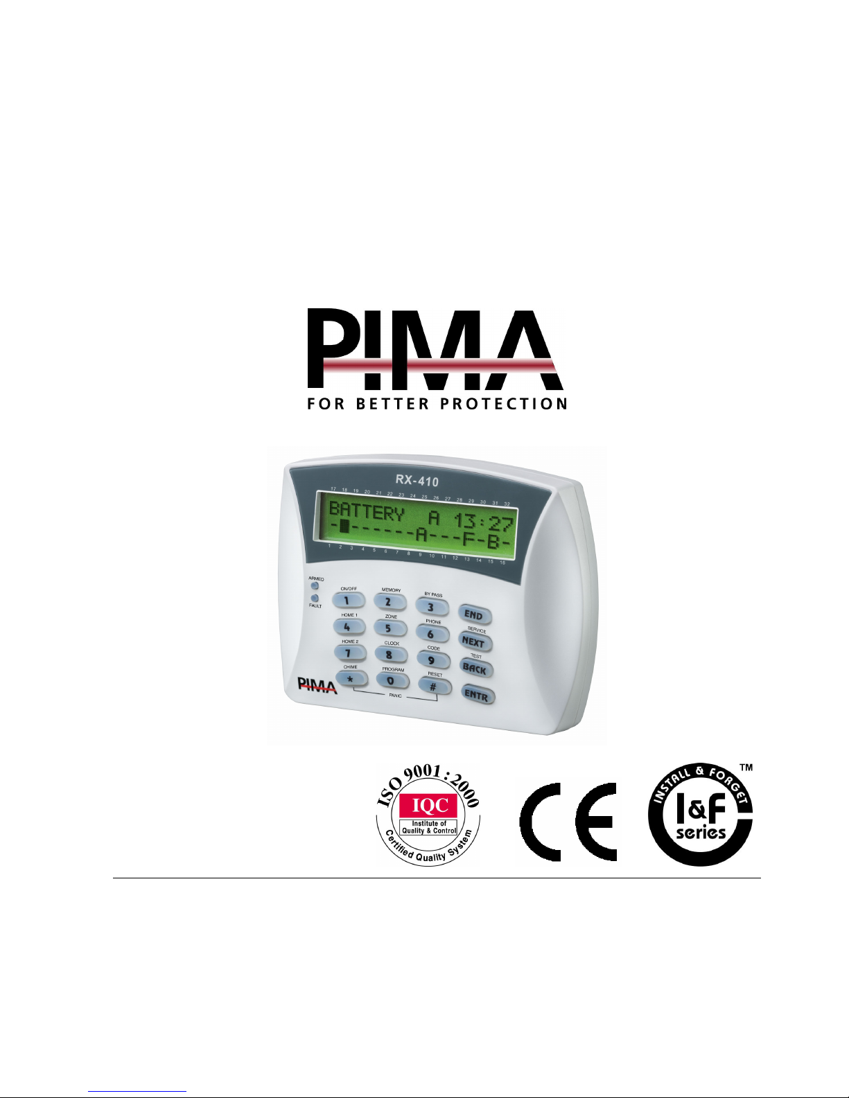
HUNTER-PRO
Intruder Alarm System
User Manual
P/N 4410066 Rev. D (Jan-2004)
PIMA Electronic Systems Ltd.
5 Hatzoref Street, Holon 58856, Israel
℡
+972-3-5587722
+972-3-5500442
http://www.pima-alarms.com
Page 2

PIMA Electronic Systems Ltd. does not represent that its Product may not be compromised
and/or circumvented, or that the Product will prevent any death, personal and/or bodily injury
and/or damage to property resulting from burglary, robbery, fire or otherwise, or that the
Product will in all cases provide adequate warning or protection. The User understands that a
properly installed and maintained equipment may only reduce the risk of events such as
burglary, robbery, and fire without warning, but it is not insurance or a guarantee that such
will not occur or that there will be no death, personal damage and/or damage to property as a
result.
PIMA Electronic Systems Ltd. shall have no liability for any death, personal and/or bodily
injury and/or damage to property or other loss whether direct, indirect, incidental,
consequential or otherwise, based on a claim that the Product failed to function.
Warning:
The user should follow the installation and operation instructions and among other
things test the Product and the whole system at least once a week. For various reasons,
including, but not limited to, changes in environment conditions, electric or electronic
disruptions and tampering, the Product may not perform as expected. The user is advised to
take all necessary precautions for his/her safety and the protection of his/her property.
This document may not be duplicated, circulated, altered, modified, translated, reduced to any
form or otherwise changed, unless PIMA’s prior written consent is granted.
All efforts have been made to ensure that the content of this manual is accurate. Pima retains
the right to modify this manual or any part thereof, from time to time, without serving any prior
notice of such modification.
Please read this manual in its entirety before attempting to program or operate your system.
Should you misunderstand any part of this manual, please contact the supplier or installer of
this system.
Copyright 2004 by PIMA Electronic Systems Ltd. All rights reserved.
You can contact us at:
PIMA Electronic Systems Ltd.
5 Hatzoref Street, Holon 58856, Israel
http://www.pima-alarms.com
Page 3
HUNTER-PRO Intruder Alarm System - User Manual
3
Table of Contents
Chapter 1 Introduction ................................................................................ 5
1.1
Main Features of the HUNTER-PRO ...................................................5
1.2
Operating Codes ................................................................................6
Chapter 2 Keypads and the Remote-Control................................................... 9
2.1
Introduction .......................................................................................9
2.2
Keypads Description ..........................................................................9
2.2.1 Zone Statues Codes.......................................................................10
2.2.2 System Status Codes......................................................................11
2.3
List of Key Functions ........................................................................11
2.4
Outdoor Anti-Vandal Keypad ...........................................................12
2.5
The Remote Control .........................................................................13
Chapter 3 System Functions ....................................................................... 15
3.1
Arming and Disarming .....................................................................15
3.1.1 Auto Arming .................................................................................16
3.1.2 Zone Bypass .................................................................................17
3.1.3 Bypass Entry Countdown ..............................................................18
3.1.4 Alarms ..........................................................................................18
3.2
Chime ..............................................................................................18
3.3
Panic................................................................................................19
3.4
Onboard Relay.................................................................................19
3.5
Keypad Buzzer.................................................................................20
3.6
System Self-Test................................................................................20
3.7
View History Log..............................................................................20
3.8
Programming....................................................................................21
3.8.1 Codes ...........................................................................................21
3.8.2 Entering Names.............................................................................25
3.8.3 Private Telephone Numbers
............................................................25
3.8.4 Time and Date ..............................................................................28
3.9
Telephone Remote Controlling.........................................................28
3.10 Partitions ..........................................................................................29
Page 4

HUNTER-PRO Intruder Alarm System - User Manual
4
Chapter 4 Troubleshooting ........................................................................ 30
4.1
Troubleshooting ...............................................................................30
4.2
Wireless Detectors for Walk-Test......................................................31
4.2.1 Wireless Event Histories................................................................32
4.3
Code Related Problems ....................................................................33
Page 5
HUNTER-PRO Intruder Alarm System - User Manual
5
Chapter
1
Introductio
Congratulations on your purchase of the HUNTER-PRO Intruder Alarm System. Much care
has been taken in developing the HUNTER-PRO Intruder alarm system, which will provide
you with unprecedented peace of mind. The HUNTER-PRO’s user-friendly operation and
advanced features will professionally protect your home or business.
It is important to familiarize yourself with the HUNTER-PRO Intruder Alarm System in
order to take full advantage of the complete range of the HUNTER-PRO’s features. To
assure optimum safety and security, you should test the HUNTER-PRO Intruder Alarm
System once a week.
The HUNTER-PRO Intruder Alarm System offers a choice of different keypad models. All but one
(RX-200) are equipped with a Liquid Crystal Display (LCD). For complete instructions on
operating, accessing, and programming your HUNTER-PRO Intruder Alarm System, using the
supplied keypad model, please turn to the appropriate chapter as listed below:
For operating and programming with all
LCD Keypad Models (i.e.,RX-150, RX-160
, and
RX-400, RX-410)
, see sections 2.2 to 2.3.
For operating with
Keypad Model RX-200 (Anti-Vandal)
, see section 2.4
1.1 Main Features of the HUNTER-PRO
!
8 to 16 zones plus two Tamper zones
!
Dials on alarms to four private telephone numbers, plus one
“Follow Me” number
NOTE:
The HUNTER-PRO dials first to the monitoring station (If you are connected to a
monitoring station), then, it dials the private telephone numbers as programmed.
You can program the private numbers (refer to section 3.8.3), while only the
technician can program the telephone numbers to the monitoring stations.
!
Various ways to arm and disarm the system: keypad, key, remote
control, touch-tone telephone
Page 6
HUNTER-PRO Intruder Alarm System - User Manual
6
!
Two families of keypads: Internal keypads such as the RX-150, RX-160, RX-400, and
RX-410 and weather and vandal-Proof keypad (RX-200) for outdoor installation
!
Connects up to eight different keypads
!
Choice of arming modes: Full, Home1, and Home2
!
Up to 16 partitions, each one with its own user code
!
Up to 410 System Events in history log (memory)
!
A variety of operating codes: Master Code, up to 16 User Codes,
Short Code, Duress Code (used during a hold up), and Relay
Activation Code (e.g., to operate an electric gate)
!
Automatic arming (time and/or motionless programming)
!
Remote control via touch-tone telephone
!
Temporary manual and/or automatic bypass of zones
!
“Chime” mode per zone: activates the keypad buzzer when a zone
is opened (e.g., to monitor a back door when system is disarmed)
!
Double communication to Monitoring Stations by telephone and
Long-Range VHF/UHF Radio Transmitter
!
Connection to a local printer to print all events
!
Connection to an external PIMA output card to activate auxiliary
devices such as video cameras etc.
!
Enabled for expansion (zone doubling, wireless, etc.)
!
Enabled to use two End Of Line resistors that will further secure the
alarm system against SHORT and CUT
!
Enabled to operate with up to 16 wireless detectors (add-on)
1.2 Operating Codes
You have five code types with which you can control different functions of the
HUNTER-PRO:
!
Master Code: Use this code to access various programming
options. The default factory
Master Code
is
5555
. For safety
reasons, we recommend not to use this Code to arm or disarm the
system.
IMPORTANT!
We recommend that you change the default factory Master Code as soon as you
start to use your new alarm system.
!
User Code: You can program up to 16 different user codes to arm
and disarm the system.
Page 7
HUNTER-PRO Intruder Alarm System - User Manual
7
NOTES:
You can program a name for each user code. This user name will appear when
viewing the ‘history log.’
!
Short Code: A two-digit code with which you can ONLY arm the
system.
!
Hold-Up Code
(Duress Code): This code is ONLY for disarming the
system during a robbery, but is useful ONLY if the system is
connected to a Monitoring Station.
!
Relay Code
: Use this code to change the status of the control
panel’s internal relay from ON to OFF and vise versa. The relay
can be used for various applications (e.g., opening/closing an
electric gate, opening an electromagnetic door lock, etc.).
NOTES:
The letter R is displayed to the left of the clock when the relay is ON.
The installer programs the time in which the relay is ON.
The relay can also be programmed by the installer to be activated as response to
a zone alarm and/or system failure.
Page 8

HUNTER-PRO Intruder Alarm System - User Manual
8
Empty Page
Page 9
HUNTER-PRO Intruder Alarm System - User Manual
9
Chapter
2
Keypads and th
Remote-Contr
o
2.1 Introduction
You have a choice of keypad models with Liquid Crystal Display (LCD) that you can
connect to the HUNTER-PRO. All the keypads are identical in functionality and have a
display with two rows of 16 characters on each row. The keypads vary only in design and
size of display. The instructions in this manual refer to the RX-410. However, all the
functions and operations are identical to all the keypads.
The keypads are used to control and program the system. Each button on the keypads has
a specific function as describes either on or above the appropriate key.
Every programming action begins with entering the master code after which the
display will show:
Select: OFF
NOTE:
You can only program the system when it is disarmed (on display:
Select:OFF
)
From this point on each key functions according to what is written above it;
telephone, code, chime, etc.
2.2 Keypads Description
These are the available LCD keypad models:
RX-150 RX-160 RX-400 RX-410
Page 10
HUNTER-PRO Intruder Alarm System - User Manual
10
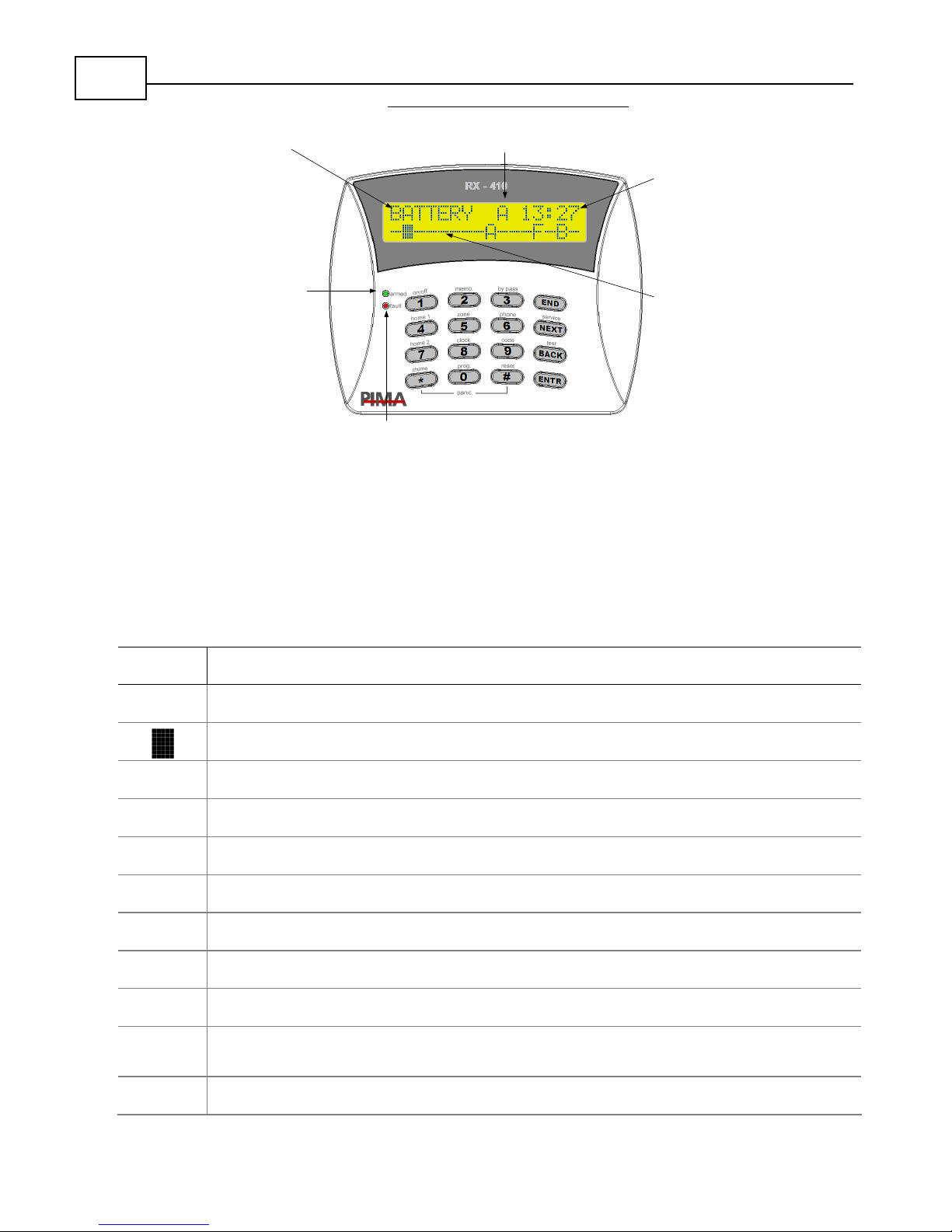
Keypads – Essential Features
Fault Notification:
The red FAULT light
blinks when a fault
is detected. A
description of the
fault appears in the
display.
Clock Display:
The time (based
on a 24 hour
clock) is shown in
the upper right
area of the
display.
Fault
Description:
The Fault
description
shown in this
sample display
indicates a
battery failure.
17 18 19 20 21 22 23 24 25 26 27 2 8 29 30 31 3 2
12345678910111213141516
Armed Indicator:
The green
ARMED
light provides the
system arm status
as follows:
Off:
System is
Disarmed.
On:
The alarm
system is in Arm
mode.
Blinking:
The
system is in Entry
or Exit Delay
Time Mode.
Zone Status:
The status of
each zone is
listed under its
number (see
table below for
further zone
statuses).
System Status Codes:
"A" indicates system is in Auto-Arm mode
2.2.1
Zone Statues Codes
The following zone status symbols appear in the display:
Symbol Status
-
Closed Zone
Open Zone
B
Bypassed Zone
A
Alarm was triggered while system was armed
C
Chime Zone
F
Faulty Zone (disconnected wires)
L
Low battery level
O
Armed zone in a partitioned system
S
Short Zone (short in wires)
V
Supervision signal not received from the detector; Indication accompanied by a
“Wireless Detector” failure indication
WrlssRec
on display, including time)
X
Armed partition
Page 11
HUNTER-PRO Intruder Alarm System - User Manual
11
2.2.2
System Status Codes
Appear to the left of the clock:
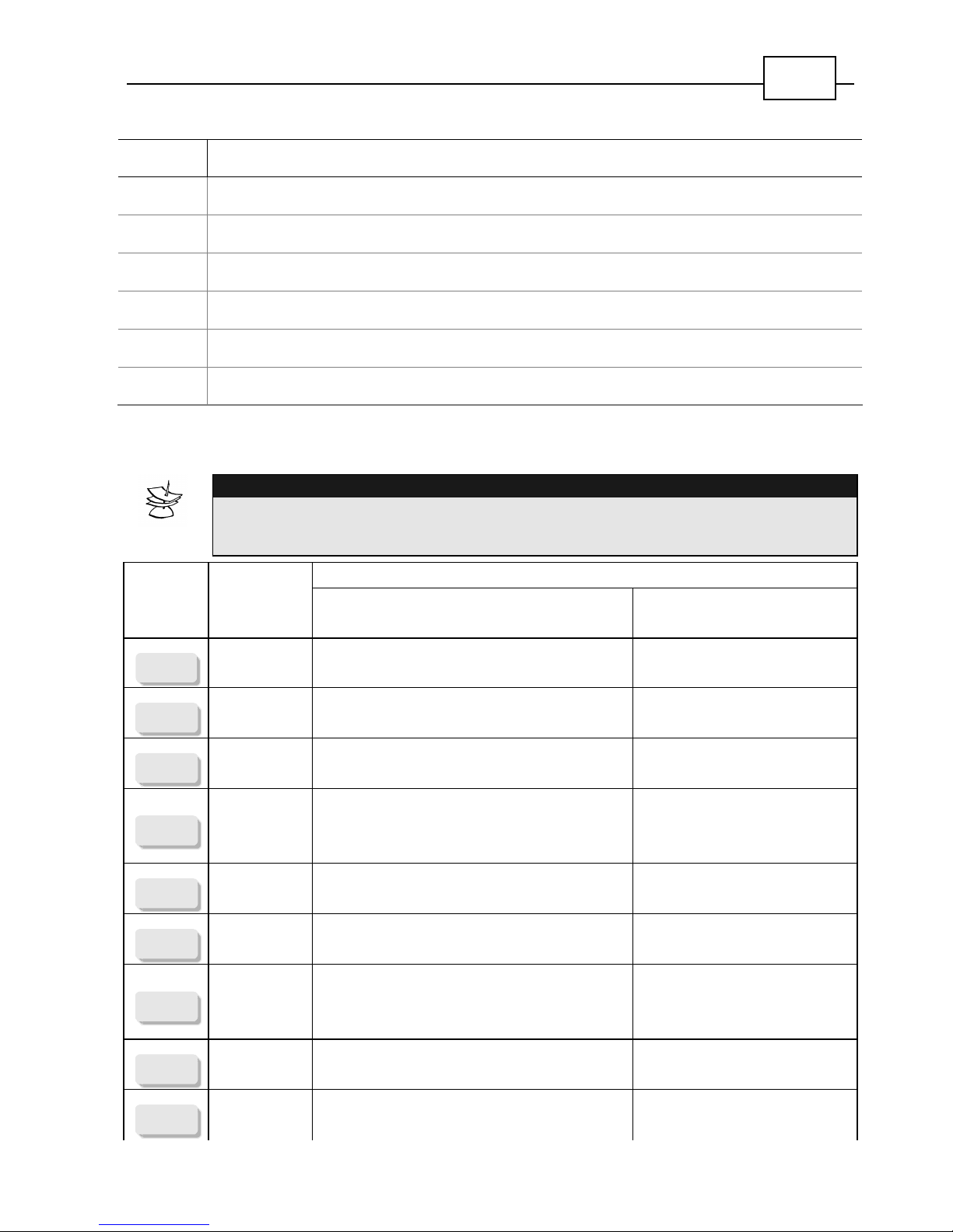
2.3 List of Key Functions
NOTE:
To access the ‘Secondary Function’, use a
long press
: press and hold the key until you
hear a long beep.
Function
Key Description
After entering Master Code
(short press)
Secondary Function
(long press)
1
ON/OFF
ON/OFF
System Arming/Disarming
2
MEMORY
MEMORY
Display arming, alarm, and fault histories Successive display of arming,
alarm and fault history
3
BYPASS
BYPASS
Temporary bypass of zones Bypass of zones or Display of
bypasses zones
4
HOME 1
HOME 1
Arming the system to mode “Home 1”
(partial arming)
Arming the system to mode
“Home 1” (enter one of the
codes after the long press)
5
ZONE
ZONE
Display all zones by name Automatic scrolling of all
open zones by name
6
PHONE
PHONE
Programming telephone numbers (view/
edit/ test)
Automatic scrolling of private
telephone numbers
7
HOME 2
HOME 2
Arming the system to mode “Home 2”
(partial arming)
Arming the system to mode
“Home 2” (enter one of the
codes after the long press)
8
CLOCK
CLOCK
Programming time and date
9
CODE
CODE
Programming the user codes
Symbol Status
P
System is communicating via phone lines
S
Siren is ON
R
Relay is active (ON)
T
System is sending transmission via long-range radio
A
System is in Auto-Arm mode
W
Walk-Test
Page 12
HUNTER-PRO Intruder Alarm System - User Manual
12
*
CHIME
CHIME
Programming zones for Chime feature Enabling/Disabling the Chime
feature
0
PROGRAM
PROGRAM
Programming automatic arming Enabling/Disabling entry
delay time
#
RESET
RESET
Programming key Smoke detector reset
END
END
Programming key
NEXT
SERVICE
NEXT
Programming key Display service Provider
information
BACK
BACK
1. Programming key
2.
Test siren, battery, and
telephone line
Test siren, battery, and
telephone line
ENTR
ENTER
Programming key
2.4 Outdoor Anti-Vandal Keypad
The RX-200 is an Anti-Vandal weatherproof keypad for
outdoor installation. It incorporates a solid-state piezo
technology touch sensitive keys, and it has three indication
lights in the form of LEDs (Light Emitting Diodes). The RX-200
can also open front-door electromagnetic locks; refer to
your installer for more information about this feature. Note
that your installer can disable the LED indications
.
Although the RX-200 does not have an LCD display, all its key functions are identical to the
regular keypads. However, programming the HUNTER-PRO with RX-200 is unsupported.
LED indications:
LED Indication
Steady The system is armed
GREEN
Blinking Pressed key/ exit or delay time
RED
Steady System fault
YELLOW
Steady All zones are closed
Page 13
HUNTER-PRO Intruder Alarm System - User Manual
13
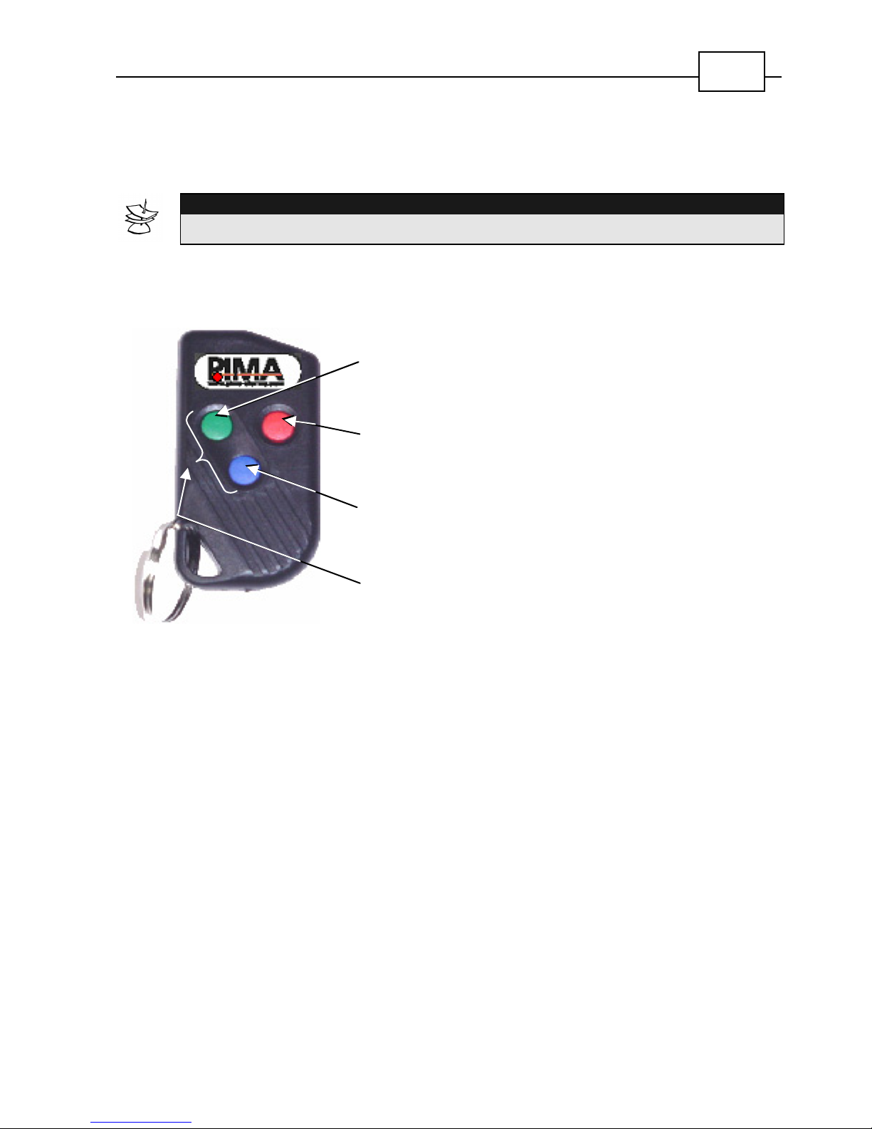
2.5 The Remote Control
The REM-3 has three buttons and is used to arm/disarm the alarm system, activate
HOME mode, and send a panic signal.
NOTE:
REM-3 is only available for HUNTER-PRO with wireless add-on system.
The remote is a Code-Hopping type (i.e., the code is changed with each operation
and thus prevents “code stealing”) with a key holder for carrying with ones keys.
ARM:
To arm the alarm system, press the GREEN
button on the remote control.
DISARM:
To disarm the alarm system, press the RED button
on the remote control.
HOME MODE:
To activate the alarm system in a Home Mode,
press the BLUE button.
PANIC:
To send a panic signal to the alarm system, press
the BLUE and GREEN buttons together.
Page 14

HUNTER-PRO Intruder Alarm System - User Manual
14
Empty Page
Page 15
HUNTER-PRO Intruder Alarm System - User Manual
15
Chapter
3
System Functio
n
IMPORTANT!
The
[
symbol indicates information in the form of letters or numbers that you
have to enter.
3.1 Arming and Disarming
You have different options to Arm and Disarm the System; remote control with your
telephone, remote control, Automatic Arming, and using your keypad as described
bellow. (Refer to the next paragraph if you must arm the system with a bypassed
zone).
!
To arm the Alarm System:
[
Any User Code one through
sixteen
OR
[
Short code.
!
To arm the Alarm System to Home1 or Home2:
Press and hold
4
HOME 1
OR
7
HOME 2
→
[
any User Code
or Short code.
!
To disarm the Alarm System: [ any User Code.
!
The
Green-ARMED
light will indicate the system status, as follows:
O Blinking: The system is in Entry or Exit Delay countdown.
O Steady Light: The system is armed.
!
To disarm the Alarm System under duress:
[
Hold-Up Code.
Page 16
HUNTER-PRO Intruder Alarm System - User Manual
16
3.1.1
Auto Arming
!
To program Auto Arming time
:
[
Master Code
[
0
PROGRAM
[
ENTR
display shows
Arming
Hour
Enter desired time in (HH:MM 24 hours format)
[
ENTR
[
END
[
END
.
!
To program Passive Auto Arming time
:
[
Master Code
[
0
PROGRAM
[
ENTR
[
display shows:
Arming
Hour
Skip entering time format and just
[
ENTR
[
display shows:
Silence Time
. Enter desired time (in minutes)
[
ENTR
[
END
.
NOTE:
When Auto Arming is programmed, the HUNTER-PRO Alarm System shall
automatically arm at the set time.
When the Silence time is set (must be greater then 5 minutes), the Alarm System
shall automatically arm when no activity is sensed (i.e., all zones are closed) for the
set time period
.
Auto Arming is indicated by the letter A in the display left to the clock.
There is no connection between programming “Auto Arming Time” and “Passive
Auto Arming Time.”
!
To cancel Auto Arming time
:
[
Master Code
[
0
PROGRAM
[
ENTR
[
#
RESET
[
END
.
[
END
Page 17
HUNTER-PRO Intruder Alarm System - User Manual
17
!
To cancel Passive Auto Arming time:
[
Master Code
[
0
PROGRAM
[
ENTR
[
ENTR
[
0
PROGRAM
[
ENTR
[
END
3.1.2
Zone Bypass
Lets you bypass a zone if you wish to leave a window open, or if the
particular zone is malfunctioning. In some systems, depending on
the configuration by the installer, zone bypass is not possible under
any circumstance if the system identifies one or more failures. In this
case you will be able to arm the system only after the failure has
been resolved.
3.1.2.1
Manual Bypass
!
Press and hold
3
BYPASS
[
Zone Number
[
ENTR
.
NOTE:
The Bypass mode is valid for one arming cycle, and the zone will be restored
when you disarm the system.
!
To restore a bypassed zone: Press and hold
3
BYPASS
[
zone number
#
RESET
.
3.1.2.2
Automatic Zone Bypass
If zones are left open while arming the system, the following message appears:
Zone Open! Press BYPASS or END
Followed by this message:
OP: Zone Name
(the one you have assigned), and the zone number
below it,
Z1
(i.e., Zone 1)
Page 18
HUNTER-PRO Intruder Alarm System - User Manual
18
Press
END
to stop the arming procedure, or press
3
BYPASS
to bypass the
open zone and commence with the exit countdown. You must press one of the two
choices; otherwise the system will automatically commence with the exit countdown
and sound the alarm once it is armed.
The zone that you bypassed will be restored when you disarm the system.
3.1.3
Bypass Entry Countdown
This feature cancels the Entry delay time countdown. Thereby,
triggering an alarm as soon as any zone/entrance is opened.
The bypass is valid for only one arming cycle. You must bypass
the entry countdown before you enter an arming code:
!
To temporarily bypass the Entry Delay Time: Press and hold
0
PROGRAM
.
3.1.4
Alarms
3.1.4.1
From fire and smoke detectors
Smoke and fire detectors require a “Reset” command after they have been activated.
!
To reset the smoke or fire detector output: Press and hold
#
RESET
.
3.1.4.2
From any zone
!
To identify a zone that triggered an alarm: The letter A is
displayed above the Zone number that triggered the alarm.
3.2 Chime
This feature activates a buzzer in the keypad when a Chime
Zone is triggered. This feature is useful to monitor doors and
entrances when the system is disarmed.
!
To define a Chime Zone
:
[
Master Code
[
*
CHIME
[
zone number
[
ENTR
[
END
.
Page 19
HUNTER-PRO Intruder Alarm System - User Manual
19
NOTE:
The letter C (for Chime) in the display above the zone number is visible only
after you enter the Master code.
!
To cancel a Chime Zone
:
[
Master Code
[
*
CHIME
[
Zone Number
[
#
RESET
[
END
.
!
To enable the Chime feature: Press and hold
*
CHIME
. The
message:
Chime is Active
is displayed for about 3
sec on the LCD display.
!
To disable the Chime feature: Press and hold
*
CHIME
. The
message:
Chime non Active
is displayed for about
3 sec on the LCD display.
NOTE:
When you enable and disable the Chime feature, you collectively enable and
disable the chime feature for all the zones that are defined as Chime Zones.
3.3 Panic
!
To initiate a Panic Response: Press and hold
*
CHIME
and
#
RESET
simultaneously for two seconds.
NOTE:
You can customize your system's response to a panic event, for example, calling
the Monitoring Station or your private telephone number, activate a relay (video
camera), activate siren, etc. Consult your installer about programming the
appropriate Panic Response for your needs.
3.4 Onboard Relay
Page 20
HUNTER-PRO Intruder Alarm System - User Manual
20
The HUNTER-PRO has an on-board relay to activate
auxiliary devices such as video cameras and external
floodlights. You can control the relay from the keypad and from
a touch-tone telephone; refer to section 3.9 for instructions on
controlling the HUNTER-PRO from telephones.
3.5 Keypad Buzzer
!
To silence the keypad buzzer:
[
END
and
ENTR
simultaneously.
NOTE:
All
audible tones and indications from the keypad are silenced.
Silencing is valid only for the particular keypad in which you performed silencing.
!
To enable a keypad's buzzer:
[
END
and
ENTR
simultaneously
, until you hear a short beep.
3.6 System Self-Test
This feature generates a self-test that tests the battery, telephone
line, and more. You will be notified of the failure if the system
indeed finds one.
!
To initiate system test:
[
Master Code
[
BACK
.
!
To stop system test execution:
[
END
.
3.7 View History Log
!
To view history log,
Press and hold
2
MEMORY
. The history
events will
automatically
progress from the most recent event to the
oldest event.
OR, if you wish to scroll between the events manually:
Page 21
HUNTER-PRO Intruder Alarm System - User Manual
21
[
Master Code
[
2
MEMORY
. In order to scroll up and
down between the events manually, use the
BACK
and
NEXT
SERVICE
keys.
!
[
*
CHIME
to advance 10 events forward.
!
[
END
[
END
to exit the mode and re-enter the
main display.
3.8 Programming
IMPORTANT!
The first step in programming any parameter in HUNTER-PRO begins with
entering a valid Master Code, after which you will see the message
Select:OFF
in the keypad’s display.
You must press the
ENTR
key after you enter new data in order to save it.
You can exit the programming mode any time without saving any changes by
pressing the
END
key two or three times.
3.8.1
Codes
3.8.1.1
Master code
!
To program a Master Code:
[
Master Code
[
9
CODE
[
ENTR
[
New
Master Code (4 to 6 digits)
[
ENTR
[
END
[
END
.
Page 22
HUNTER-PRO Intruder Alarm System - User Manual
22
3.8.1.2
User codes
!
To program User Code #1: [ Master Code
[
9
CODE
[
NEXT
SERVICE
[
ENTR
[
new User Code (4 to 6
digits)
[
ENTR
[
enter start/stop time frame∗
[
ENTR
[
enter user name (see table in section 3.8.2 in
order to view ABC keypad letters)
[
ENTR
[
enter
partition number (when applicable)
[
ENTR
[
END
[
END
.
NOTE:
You can program each User Code to be active in a certain time window, and also
assign it to a partition (see section 3.10). To enable the User Code at all times; set the
Start time at 00:00 and Stop time at 23:59 (factory default).
!
To delete a User Code #1:
[
Master Code
[
9
CODE
[
NEXT
SERVICE
[
ENTR
[
#
RESET
[
END
[
END
.
!
To program User Codes #2 through #16: [ Master Code
[
9
CODE
[
NEXT
SERVICE
(as many times as the User Code
number)
[
ENTR
[
follow instructions as with User #1.
∗
Use the
NEXT
SERVICE
and
BACK
keys to scroll between Hour/Minutes/Start/Stop,
Page 23
HUNTER-PRO Intruder Alarm System - User Manual
23
!
To delete User Code #2 through #16
:
[
Master Code
[
9
CODE
[
NEXT
SERVICE
(as many as the User Code
number)
[
ENTR
[
#
RESET
[
END
[
END
.
g
Example:
In order to program or delete User Code #6, enter the Master Code, press the
9
CODE
key, followed by pressing the
NEXT
SERVICE
key six times.
3.8.1.3
Hold-Up Code
!
To program a Duress Code:
[
Master Code
[
9
CODE
[
BACK
(until
Hold Up
code is displayed)
[
ENTR
[
new Hold-Up Code (4 to 6 digits)
[
ENTR
[
END
[
END
.
!
To delete a Duress Code:
[
Master Code
[
9
CODE
[
NEXT
SERVICE
(until
Hold Up
is displayed)
[
ENTR
[
#
RESET
[
END
[
END
.
Page 24
HUNTER-PRO Intruder Alarm System - User Manual
24
3.8.1.4
Short Code
!
To program a Short Code:
[
Master Code
[
9
CODE
[
BACK
(until
Short Code
is displayed)
[
ENTR
[
New Short Code (2 digits)
[
ENTR
[
END
[
END
.
!
To delete a Short Code:
[
Master Code
[
9
CODE
[
BACK
(until
Short Code
is displayed)
[
ENTR
[
#
RESET
[
END
[
END
.
3.8.1.5
Relay Code
!
To program Relay Code:
[
Master Code
[
9
CODE
[
BACK
(until
Relay Code
is displayed)
[
ENTR
[
new Relay Code (4 to 6 digits)
[
ENTR
[
END
[
END
.
!
To delete Relay Code:
[
Master Code
[
9
CODE
[
BACK
(until
Relay Code
is displayed)
[
ENTR
[
#
RESET
[
END
[
END
.
Page 25
HUNTER-PRO Intruder Alarm System - User Manual
25
3.8.2
Entering Names
When you program User Codes, you can also assign a User Name for each code. To
program names use the keypad according to the following layout:
END
54 6 NEXT
87 9 BACK
0
*
# ENTR
321
P Q R 6 M N O 5J K L 4
G H I 3 D E F 2 A B C 1
Y Z 9V W X 8 S T U 7
0 , . +( ) - ' space
NOTE:
Press the
#
RESET
key to delete an existing name.
To move the cursor to the right and left; press the
BACK
and
NEXT
SERVICE
keys.
g
Example:
To program the name PIMA, do the following:
[
6
PHONE
[
NEXT
SERVICE
[
3
BYPASS
[
3
BYPASS
[
3
BYPASS
[
NEXT
SERVICE
[
5
ZONE
[
NEXT
SERVICE
[
1
ON/OFF
[
ENTR
(to save name)
3.8.3
Private Telephone Numbers
!
To program a temporary Follow-Me telephone number:
[
Master Code
[
6
PHONE
[
ENTR
[
Telephone Number
[
ENTR
[
END
[
END
.
Page 26
HUNTER-PRO Intruder Alarm System - User Manual
26
IMPORTANT!:
The Follow-Me number is valid for one arming cycle and will be erased when system
is disarmed
.
!
To program a telephone number (1 to 4)
:
[
Master Code
[
6
PHONE
[
NEXT
SERVICE
[
NEXT
SERVICE
[
Telephone Sequence Number (1 to 4)
[
Telephone Number
[
ENTR
[
END
[
END
.
g
Example:
To program Telephone #2 as 33-1-12345678, enter the Master Code, press the
6
PHONE
key, press
NEXT
SERVICE
twice, press
2
MEMORY
,
[
enter the phone
number (e.g., 33112345678), press
ENTR
, and end with pressing
END
twice.
NOTES:
You can program up to four telephone numbers to which the HUNTER-PRO will call in
an emergency.
If you connect the HUNTER-PRO Alarm System on a PBX extension, remember to
enter the prefix number and an asterisk before the telephone number, e.g., 9*555-
5555. For simplicity, you can ask the installer to program the prefix number such that
the system will automatically dial it before every number it dials.
The HUNTER-PRO Alarm System calls all telephone numbers and plays a
synthesized tone when you pick up the phone. Dial your Master Code and then “0”
(zero) on your
touch-tone telephone
to command the HUNTER-PRO to stop dialing
the rest of the telephone numbers.
You can ask your installer to install an optional VU-20 unit that will play a pre-recorded
message instead of the synthesized tone.
Page 27
HUNTER-PRO Intruder Alarm System - User Manual
27
!
To view programmed telephone numbers
:
[
Master Code
[
6
PHONE
[
NEXT
SERVICE
[
Telephone sequence
number. Now
[
ENTR
and then
NEXT
SERVICE
OR
BACK
to scroll between numbers
[
END
[
END
[
END
.
!
To test a programmed telephone number:
[
Master Code
[
6
PHONE
[
NEXT
SERVICE
[
NEXT
SERVICE
[
NEXT
SERVICE
[
Telephone Sequence
Number (1 to 4).
[
END
. To stop the test
[
END
[
END
.
!
To delete a telephone number (1 to 4)
:
[
Master Code
[
6
PHONE
[
NEXT
SERVICE
[
NEXT
SERVICE
[
Telephone
sequence number (1 to 4)
[
#
RESET
[
END
[
END
.
Page 28
HUNTER-PRO Intruder Alarm System - User Manual
28
3.8.4
Time and Date
!
To set the time and date
:
[
Master Code
[
8
CLOCK
[
Time (HH:MM 24 hours format)
[
ENTR
[
Date
(YYYY MM DD format)
[
ENTR
[
END
.
NOTES:
Correct time and date is important for proper functioning of the HUNTER-PRO
Alarm System.
The HUNTER-PRO Alarm System will report a failure if you don’t enter the
time and date after a complete power failure (AC and Battery).
The HUNTER-PRO Alarm System will not accept incorrect data. For example, if
you enter 25:25 for the hour, the programming will be stopped automatically, and
you will have to start the procedure from the beginning.
3.9 Telephone Remote Controlling
!
To access the panel via a touch-tone phone:
O Dial the telephone number to which the Alarm System is connected.
O Wait for the system to pick up the call, wait for the system to complete the
playing of the synthesized tone or the pre-recorded message (If a VU-20 is
installed), and dial the
Master Code.
O
Listen to the system STATUS tone:
A
continues tone -----------------
: Alarm System is disarmed
An
intermittent tone . . . . . . . .
: Alarm System is armed
Note: Wait for the status tone to stop before you continue.
O Execute the following commands by pressing keys on your touch-tone phone.
Telephone key: Function:
1 Arm the system
2 Disarm the system
4 Arm the system in “Home 1” mode
5 Switch on the Relay
6 Switch off the Relay
7 Arm the system in “Home 2” mode
8 Listen in (only available with a MIC-100)
0 Disables siren and dialer (in case of an alarm).
NOTE:
The alarm system confirms the command was received by two short tones.
Page 29
HUNTER-PRO Intruder Alarm System - User Manual
29
3.10 Partitions
The HUNTER-PRO can be programmed to function as several independent
subsystems called “Partitions.”
One or more zones can be allocated to each partition, with one User Code for
each partition. Each User Code can be assigned to control one partition or the
entire system as in regular operating mode.
The installer programs the zones allocated for the different partitions, while the
user programs the User Codes for the different partitions (for programming User
Codes, see section 3.8.1.2).
Keypad display of a system with partitions:
1 3 : 4 5
O O O O ----
The letter O represents the armed zones assigned to one or more armed partitions.
A r m e d Partition
X XXX
The letter X is displayed above the partition number that is armed.
When all the zones are armed, the system will show
ON
on the display, and the green
light will be on. When only some of the zones are armed, the green light is off.
NOTES:
The above two screens are continuously displayed one after the other every five
seconds.
Each zone can be assigned to more than one partition. Such a zone will trigger
an alarm only if all the partitions to which it is associated are armed.
Page 30
Anti-Vandal Keypad Model
30
Chapter
4
Troubleshootin
The HUNTER-PRO regularly checks itself and the devices that are connected to it. The
red failure indication lamp will blink if the HUNTER-PRO detects any failure, and in some
cases a failure will be reported to the monitoring station and/or private telephone number
(according to installation programming.) A description of the failure will be displayed in
the keypad and the failure event will be saved in the system memory with date and time.
4.1 Troubleshooting
NOTE:
If more then one failure is detected, the display will scroll the failure list one after
the other. If more than one keypad is connected to the HUNTER-PRO, and you
are programming the system from one keypad, then the display on all other
keypad will display:
Other display is used
This will also be
displayed whenever the installer uses a modem in order to program the HUNTERPRO, or when someone is in control of the HUNTER-PRO
via telephone.
The following table describes the possible Alarm System Faults:
Displayed
Fault
What can I do?
Battery
Wait approximately 24 hours for the indication to disappear. If the fault
indication persists longer then one day, the back-up battery should be replaced.
Wireless
Receiver
A wireless receiver failure can be the cause of communication
failure between the detector and receiver.
AC voltage
Usually appears during a power failure. If other electrical appliances in the
house are operating, check the switch or fuse to which the alarm system is
connected. If the cause of the fault is unclear, call the installer.
Clock
Appears following a prolonged power failure during which the backup battery
was completely discharged. Set time and date (see section 3.8.4)
Displayed
Fault
What can I do?
Phone
Perform “system self-test” (see section 3.6). Verify during the test that other
instruments connected to the Alarm System’s telephone line (i.e., telephone sets,
Page 31
HUNTER-PRO Intruder Alarm System - User Manual
31
facsimiles, etc.) are not active. If the fault persists, call the installer.
Tamper 1
Tamper switch 1 is open. Call the installer.
Tamper 2
Tamper switch 2 is open. Call the installer.
Low pwr
Appears before the back-up battery is completely discharged, usually after a
prolonged power failure. Follow instruction for low battery failure.
EEPROM
Parameter programming fault. Call the installer.
Zone Trb.
One of the protected zones is faulty. Call the installer.
ROM
Software failure. Call the installer.
RAM
System failure. Call the installer.
Commun.
Failure to communicate with Monitoring Station. Call the installer.
Det. Vltg
Detector power supply. Call the installer.
Keypad not
connected
No communication between the keypad and the HUNTER-PRO motherboard.
Call the installer.
Other display
use
Programming is done from another keypad or system is controlled via
telephone.
4.2 Wireless Detectors for Walk-Test
“
Walk Test” tests the strength of the radio transmission from the detector to the
HUNTER-PRO
only. During the Walk Test, the display will show the letter W.
The Walk Test is valid for only 10 minutes from the time you start it. After 10 minutes
you have to restart the Walk Test from the beginning.
Press
END
any time to end the Walk Test procedure.
While performing the Walk Test, the name of the zone with its associated reception
quality (Radio Strength Signal Indicator) will be displayed in readings from 1 to 10
where 10 represents the best reception quality.
Page 32
Anti-Vandal Keypad Model
32
In addition, the keypad will release tones in varying frequencies where the
highest frequency represents the better reception. The wireless detectors will be
automatically tested one after the other, and the readings will be saved in the system
memory for future reference.
!
To Start the Walk Test
:
[
Master Code
[
#
RESET
!
In the display you will see the following:
E N T R =TEST WL AL L
N E X T =TAMPER ONL Y
Press ENTR to check the reception quality from all wireless devices.
Press NEXT to check the reception quality only from the TAMPER reading. The
system will display only the readings associated with the TAMPERS of the wireless
devices. Before you initiate the TAMPER test, open the wireless detector housing and
press on the tamper switch – from now on, the wireless detector will transmit a
“tamper code” and the associated reception reading will be displayed on the keypad.
Example of Walk Test displays:
W 1 2 : 3 4
- - - - ----------- -
L i v i ng Room
1 0 Z 1 2
Reception quality from Z12, the living room, is 10.
4.2.1
Wireless Event Histories
The following are display examples of wireless events in the history memory
Low battery in Zone 3.
Page 33
HUNTER-PRO Intruder Alarm System - User Manual
33
1 4 ) Zone 3
B A T AUG0105:1 2
Supervision signal was not received from Zone 5
1 5 ) Zone 5
S P R FEB 22 01:5 2
Reception Test from Zone 12, Reception quality = 7.
1 6 ) Zone1 2
R S S=7 12:02 R S
No communication with the wireless receiver.
1 7 ) WL unit fai l
D E C 11 05:12D E C
Wireless receiver communication frequency is blocked (
Jammed
).
1 9 ) WL unit jam m
A P R 17 15:54A P R
4.3 Code Related Problems
!
Codes do not arm or disarm the system:
E
nter the Code again. If that does not solve the problem, program
the code again.
!
User Code does not disarm the system:
Check the Time Frame allocated for the User Code (see section
3.8.1.2)
 Loading...