

Pima Captain 8 HunterPro 832, Captain 8 HunterPro 896, Captain 8 HunterPro 8144, Captain 8 User Manual

HunterPro
832/896/8144
Captain8
S e c u r i t y
S y s t e m s
UserGuide

Turn ON/Off
the chime
feature in chime
Reset smoke detectors.
BYPASS
2 HUNTER-PRO Series & CAPTAIN 8 User Guide
Quick Reference
Key
ON/OFF
Press for 2 seconds, enter
User code and press the key to...
Arm to full mode, disarm Quickly arm to full mode*
1111
Display the log -
Temporarily bypass zones -
3333
Arm to “Home 1” mode Quickly arm to “Home 1” mode*
Display modes menu Display the “All Zones” mode for a minute
Set the telephone numbers -
Arm to “Home 2” mode Quickly arm to “Home 2” mode*
Set time and date -
Set the user codes -
Set the chime per zone
Set auto-arming by day and inactivity -
-
- Silence the keypad buzzer when it beeps
Display the system’s name & version Display the service provider
Initiate system tests -
ENT R
ENT R
ENT RENT R
ENT R
ENT R
ENT RENT R
+
+
Press for 2 seconds: create Panic alarm
Press briefly: turn ON/OFF the keypad chime
- Display the system’s name & version
Factory default codes
Master: 5555
Technician: 1234
Press the key for 2 seconds∗ to...
zones
Press briefly: display armed partitions
∗
Commands marked with an asterisk must be enabled by the Installer.

HUNTER-PRO Series & CAPTAIN 8 User Guide 3
1
INTRODUCTION .................................................................................................... 5
1.1 Hunter-Pro & Captain 8 mutual features .................................................................. 5
1.2 Hunter-Pro Series unique features .......................................................................... 5
1.3 Captain 8 unique features ..................................................................................... 6
1.4 Safety & Security ................................................................................................. 6
1.5 Signs and conventions in this guide ........................................................................ 6
1.6 System codes ...................................................................................................... 7
1.6.1 The Master code ............................................................................................ 7
1.6.2 User codes ................................................................................................... 7
1.7 The User Menu .................................................................................................... 7
1.8 The LCD Keypad .................................................................................................. 7
2
ARMING & DISARMING THE SYSTEM (KEY #1) ......................................................... 8
2.1 Arming ............................................................................................................... 9
2.1.1 Via the keypad .............................................................................................. 9
2.1.2 Fast arming .................................................................................................. 9
2.2 Disarming ........................................................................................................... 9
2.2.1 With the DURESS code ................................................................................... 9
3
THE SYSTEM LOG (KEY #2) ................................................................................. 11
3.1 Log list sorting options ........................................................................................ 11
4
TEMPORARILY BYPASSING OPEN ZONES (KEY #3) ................................................. 12
4.1 When arming ..................................................................................................... 12
4.2 Prior to arming .................................................................................................. 12
5
“HOME 1” & “HOME 2” ARMING MODES (KEYS 4, 7) ............................................... 13
6
DISPLAYING TYPES (KEY #5) ............................................................................... 14
6.1 Fast 32-zone display........................................................................................... 14
6.2 Scan open zones ................................................................................................ 15
6.3 Disable zone displaying ....................................................................................... 16
6.4 Other displaying types ........................................................................................ 16
6.4.1 All Zones ..................................................................................................... 16
6.4.2 Bypassed Zones ........................................................................................... 16
6.4.3 Soaked Zones .............................................................................................. 17
6.4.4 Chime Zones ............................................................................................... 17
6.4.5 All Zones Status ........................................................................................... 17
6.5 Show partition names ......................................................................................... 18
7
PHONE NUMBERS, SMS SETTINGS & DIALER TEST (KEY 6) ...................................... 18
7.1 Phone numbers .................................................................................................. 18
7.2 SMS messages................................................................................................... 19
7.2.1 A demo SMS message ................................................................................... 19
7.3 Dialer test ......................................................................................................... 19
8
SETTING TIME AND DATE (KEY 8) ........................................................................ 20
9
CODES (KEY 9) .................................................................................................. 20
9.1 The Master Code ................................................................................................ 20
9.1.1 Changing the code ........................................................................................ 21
9.2 User codes ........................................................................................................ 21
9.2.1 Adding or change a code ............................................................................... 21
9.2.2 Deleting a code ............................................................................................ 21
9.3 User name ........................................................................................................ 21
9.4 User settings ..................................................................................................... 22
9.5 Disarming Time Frame ........................................................................................ 23
9.6 User’s partitions ................................................................................................. 23
9.7 Adding a key fob ................................................................................................ 24
9.8 Deleting a key fob .............................................................................................. 24
Table of Contents

4 HUNTER-PRO Series & CAPTAIN 8 User Guide
9.9 Adding RFID tag/keychain ................................................................................... 24
9.10 Deleting RFID Tag .............................................................................................. 25
9.11 The DURESS code .............................................................................................. 25
9.12 The Short code .................................................................................................. 25
9.13 The Door code ................................................................................................... 25
10 AUTOMATIC ARMING (KEY 9) ............................................................................... 26
10.1 By day and hour ................................................................................................ 26
10.1.1 Inactivity auto-arming .................................................................................. 26
11 THE CHIME FEATURE (KEY #) .............................................................................. 27
11.1 Enabling and disabling the Chime globally ............................................................. 27
12 OTHER TOPICS ................................................................................................... 27
12.1 Partitions .......................................................................................................... 27
12.1.1 Examples .................................................................................................... 28
12.1.2 Displaying armed partitions ........................................................................... 30
12.2 Arming with key, key fob or RFID tag/key chain ..................................................... 30
12.2.1 Arming with a key fob ................................................................................... 30
12.3 Enabling Remote Upload ..................................................................................... 31
12.4 Names and Characters ........................................................................................ 31
12.4.1 Example ...................................................................................................... 32
12.5 PANIC alarm ...................................................................................................... 32
12.6 Resetting Smoke/Fire/Anti-mask detectors ............................................................ 32
12.7 Turning the keypad chime ON/OFF ....................................................................... 32
12.8 Comparison between the Hunter-Pro Series models ................................................ 33
12.9 Comparison between the Hunter-Pro 896 & Captain 8 ............................................. 33
13 MANUAL SYSTEM TESTS (BACK KEY) .................................................................... 34
14 REMOTE CONTROL VIA THE PHONE ...................................................................... 34
14.1 Basic mode ....................................................................................................... 34
14.2 Full mode .......................................................................................................... 35
14.2.1 Examples .................................................................................................... 36
15 TROUBLESHOOTING ........................................................................................... 37
16 APPENDIX: ZONE LOCATION TABLE ...................................................................... 39

HUNTER-PRO Series & CAPTAIN 8 User Guide 5
1 INTRODUCTION
Congratulations on your purchase of the HUNTER-PRO Series and Captain 8 intruder alarm
systems. Much care has been taken in developing these systems, to provide you with
unprecedented peace of mind and security. The user-friendly menu with its advanced features
will professionally help you to protect your premises.
We recommend reading this guide in its entirely in order to familiarize you with the system and
take full advantage of its features.
To assure optimal safety and security, you should perform a system test once a week. See
section 13 for details.
For any further questions, please contact your local PIMA distributor.
1.1 Hunter-Pro & Captain 8 mutual features
• Hybrid systems with hardwired and wireless zones;
• Operating modes: full or partial, “HOME 1” & “HOME 2”;
• Equipped with menu-driven LCD and Graphic keypads, and cost-effective LED keypads;
• Optional use of partitions for perimeter zones and separate locations;
• Various automatic arming;
• Various codes & access options including RFID tag/keychain and key fob;
• Authorization settings per user;
• Up to four phone numbers to call the Monitoring Station and four to the owner;
• Optional disarming time frame per user;
• Constant zone, battery and phone line testing;
• Communication channels: phone, Long-range Radio, GSM, GPRS, Ethernet;
• Various ways to arm and disarm the system: keypad, key switch, RFID tag/keychain,
auto-arming;
• Full wireless detectors supervision;
• Optional alarm voice messages and listen in microphone;
• Various methods for preventing false alarms;
• Full log, part is non-volatile.
1.2 Hunter-Pro Series unique features
• 8 to 32/96/144 zones;
• Up to 32/96/144 user codes and RFID tags;
• Phone remote control;
• Various partitioning options:
Up to 16 partitions;
Up to 8 subsystems.

6 HUNTER-PRO Series & CAPTAIN 8 User Guide
1.3 Captain 8 unique features
• 8-16 zones;
• Up to 30 user codes & RFID tags;
• Various partitioning options:
Up to 4 partitions;
Up to 4 subsystems.
1.4 Safety & Security
Both the HUNTER-PRO Series & the Captain 8 systems have been registered in
accordance with the EN60950 standard.
We advise you the following:
• The alarm system as well as its wiring should be placed in a hidden and safe location,
protected from rain or moisture.
• The alarm system may have hazards of electric shock and fire. Do not try to open the alarm
system’s case: dangerous high voltages are present inside it. Refer servicing to qualified
personnel only.
• This alarm system should be used with 230VAC 50Hz, protected by anti-electric shock
breaker. To prevent electric shocks and fire hazards, do NOT use any other power source.
1.5 Signs and conventions in this guide
Press a key briefly
Press a key for 2 seconds, until confirmation beep sounds
Warning
Note
NEXT
NEXT
NEXTNEXT
BACK
BACK
BACKBACK
ENTR
ENTR
ENTRENTR
END
END
ENDEND
In programming mode, moves the cursor to the right.
In programming mode, moves the cursor to the left.
Enter, Save
####
In programming mode, enables (‘+’) or disables (‘-‘) a parameter; erase character.
Press briefly: Cancel; Return.
Press for 2 seconds: Silence the keypad chime in faults.
The numbers that are printed above and below the keypad’s screen stand for zone
numbers and partition numbers.

HUNTER-PRO Series & CAPTAIN 8 User Guide 7
1.6 System codes
1.6.1 The Master code
• The Master code is a super user code with all the access authorizations.
• It is mainly used for changing the “Master Code” itself.
• The default factory Master Code is 5555.
Replace the default Master code immediately after installation to
prevent unauthorized and illegal operations.
1.6.2 User codes
• The User code is the user’s ID. It includes the User details, access authorizations,
disarming time frame and it is reported and logged together with any action the User
is taking.
• A User code can be restricted to only parts of the user menu, i.e., can only set
these menus.
1.6.3 Short Code
• A convenient, 2-digit code used only for arming the system.
1.6.4 Duress Code
• A code for using in distress situations.
• Entering the code disarms the system when armed and generates a silent alarm to
the Monitoring Station (if one is a subscriber) and to your phone.
• The code is a 4-6 digit code.
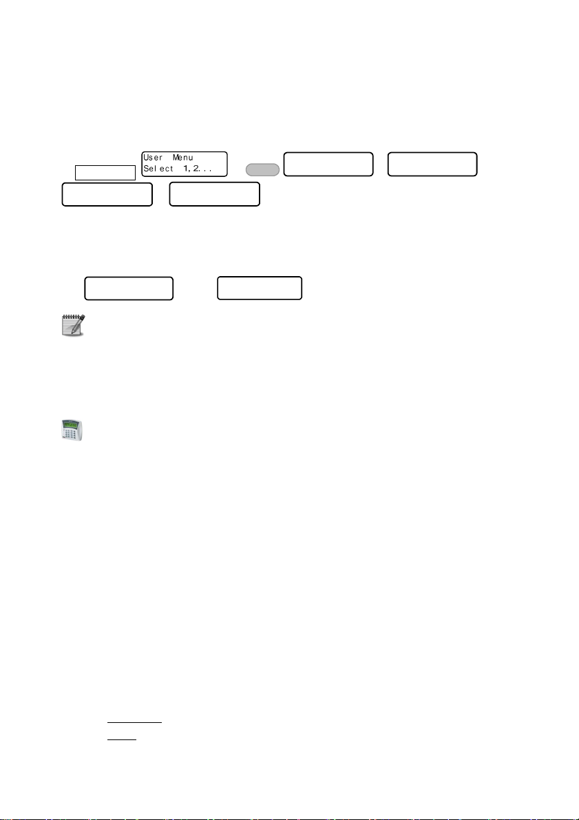
1.7 The User Menu
• The User menu is where parameters such as Time & Date, User codes and User
authorizations are set.
• It is accessed by pressing for 2 seconds and entering a User code. See section
9.4 for restrictions.
• By default, entering a User code arms or disarms the alarm system (toggle mode). The
Installer can program the system, so entering the code displays the User menu.
• After entering the User menu, the sub-menus are accessed directly, by pressing the
keypad keys. Each key menu is printed above it, e.g. “Time”, “Codes”.
1.8 The LCD Keypad
• RXN-400, RXN-410 and RXN-410 RFID are PIMA’s LCD keypads. They are designed for
maximum simplicity and durability and present decorative design.
The RXN-400 & RXN-410 are identical, except for their screen size: 410’s is larger.
0000

8 HUNTER-PRO Series & CAPTAIN 8 User Guide
• The screen is made of 2 lines with 16 characters in each. The upper line displays the time
and the date (depending on the display type). Both lines display data regarding the
system, such as events, faults and zone status.
• Up to 8 supervised keypads can be connected to the system simultaneously.
• The message “Other Keypad in Use” is displayed when another keypad is in
use, or when the system is remotely controlled.
Figure 1. RXN-410 with the “Fast” display type
2 ARMING & DISARMING THE SYSTEM
(KEY #1)
• The system can be armed in one of 4 ways:
1. Via the keypad;
2. Automatically;
3. Using Key fob, key switch and RFID tag/keychain;
4. In Hunter-Pro only: by a remote control and via the phone.
• As a rule, arming should be carried out only when all the zones are closed, but those on
the exit route, and there are no alarms (e.g., fire, panic) or faults (e.g., low battery):
In the “Fast zone” display type, no zone is indicated with a rectangle _ ;
In the “Scan open zones” display type, no zone is indicated with “OP” (open).
• Zones like exit doors and areas near the keypad are delayed on the exit and the entry, so
whoever arms (or disarms) the system will have enough time to walk from the keypad to the
door, (or the other way, when entering) without triggering any detector.
• The Exit & Entry delay times are separate and programmed by the Installer. The Installer
can also program two different Entry delays to different zones.

HUNTER-PRO Series & CAPTAIN 8 User Guide 9
2.1 Arming
• To arm your system, enter a user code (see section 9.4 for restrictions) or the Short code
(a code programmed by the Installer. See section 9.12).
• If no zone is open and there are no faults, the Exit delay countdown starts, the keypad
buzzer sounds beeps and the green ARMED LED flashes. You can now exit the premises
and close the door behind you1.
• When the Exit delay ends, the system becomes armed: the green ARMED LED stops to
flash and stays on, the beeps stop, the message “System Armed” is briefly displayed and
then the date and time are displayed.
2.1.1 Via the keypad
Sys t em Ar med !
User code ...
• The Exit delay time span is set by the Installer.
2.1.2 Fast arming
1111
until the Exit delay starts -OR- Short code ...
Sys t em Ar med !
• Fast/single keystroke arming must be enabled by the Installer.
• To set the Short code, see section 9.12.
2.2 Disarming
Di sar mi ng . .
User code …
• To disarm the system, enter a user code.
• If an “Access denied” message is displayed, the user may be trying to disarm it outside
her/his “Disarming time frame”. See section 9.5
2.2.1 With the DURESS code
Di sar mi ng . .
DURESS code …
• The DURESS code is a code to be used in threat situations, where you are being forced
to disarm the system. Hence, the code can be used only for disarming
• Entering the DURESS code disarms the system and sends a silent alarm to the Monitoring
Station (if you are subscribed to) and your phones.
• To set the code, refer to section 9.3.
1
The Exit delay countdown can start immediately as soon as the final door is closed. Refer to the Installer.
.

10 HUNTER-PRO Series & CAPTAIN 8 User Guide
3 THE SYSTEM LOG (KEY #2)
User Menu
• The system logs alarms, arming & disarming, zone bypassing, faults, code changing and
• Any action taken by a user is logged with the User name.
• Part of the log is non-volatile (see the table on page 33).
User code
other actions, chronologically.
3.1 Log list sorting options
• A log entry contains, on the upper line, a serial number and the date & time stamp when the
entry (i.e., the event) was logged; the event details appear on the bottom line.
• The log has 4 list sorting options: “All the events”, which displays all the log entries in one
list, “Faults only”, “Zone alarms” and “Arming/disarming”.
• When you view one of these lists, pressing a number between 0-3, transforms to
corresponding list: 0-“All the events”, 1-“Faults only”, 2-“Zone alarms”, 3-“Arming/disarming”.
• Entry example: “Burglary” alarm in zone #4, called “Kitchen”; the two screens are displayed
intermittently.
Choo s e 1, 2. . .

•
Bypassing zones reduces the safety of your protected premises
: a
HUNTER-PRO Series & CAPTAIN 8 User Guide 11
4 TEMPORARILY BYPASSING OPEN
ZONES (KEY #3)
bypassed zone does not sound the alarm when violated, nor does it
report the monitoring station!
• It should be used carefully, only if there is no alternative and only for
the shortest possible time.
• If you bypass a zone due to a fault, a service technician should
be called;
• Beware not to bypass zones unintentionally;
• Zones can be bypassed only when the system is disarmed;
• Temporarily bypassed zones are automatically reinstated when the system is disarmed.
• The letter “B” in “Fast zone display" mode indicates a bypassed zone.
• A service technician can permanently bypass a zone, such in the case of a zone that no
longer needs to be protected
4.1 When arming
User code to temporarily bypass the open zone/s
Ar mi ng. . .
BYPASS
Ex i t Del ay 6 0
3333
.... -OR- to cancel arming
Sys t em Ar med!
• When you try to arm the system and a 24-hour zone2 is open, the keypad sounds beeps
and the message “Open Zone! Press END or Bypass”, with the zone/s details, is displayed
in two intermittently changing screens.
• If you do not cancel arming or bypass the open zones, when the Exit delay ends the
system will be armed, but the open zones instantly sound the alarm.
• Exit delayed zones are such, so they can be left open until the EXIT delay time ends.
4.2 Prior to arming
• You can temporarily bypass zones in advance of arming the system.
As a precaution, there is a time limit, set by the Installer, for a zone to be
bypassed prior to arming. When this time ends and the system has not been
armed yet, the zone is automatically reinstated.
2
24-Hour zones sound the alarm whenever they are violated, regardless of the system status.
EN D
EN D
EN DEN D

12 HUNTER-PRO Series & CAPTAIN 8 User Guide
• To temporarily bypass a zone prior to arming:
approval message is displayed.
• For example:
User code
Be aware that a zone is bypassed immediately and stays so, until the
system is disarmed the next time (unless bypass limit time is over).
Zone Number : 1
BYPASS
Ent r - Conf #- Rst
3333
zone number …
EN TR
EN TR
EN TREN TR
• To reinstate a bypassed zone:
approval message is displayed.
• For example:
User code
Zone Number : 1
BYPASS
Ent r - Conf #- Rst
3333
zone number …
####
5 “HOME 1” & “HOME 2” ARMING
MODES (KEYS 4, 7)
• “HOME 1” and “HOME 2” are arming modes, in which only some zones are armed, while
others are not: while the armed zones sound the alarm if violated, the disarmed zones can
be occupied at the same time.
• Common applications for the Home modes are perimeter detectors and nighttime zones.
• The zones included in each Home mode are set by the Installer and require no
hardware installation.
• Arming to the Home modes is much like arming to full mode, and there is fast arming
option too.
• To arm to “HOME 1” mode:
Home 1 Ar mi ng. .
Exi t Del ay 60
User/Short code
• To arm to “HOME 2”
Home 2 Ar mi ng. .
Exi t Del ay 60
mode:
User/Short code

HUNTER-PRO Series & CAPTAIN 8 User Guide 13
• To arm to the Home modes via the User menu:
“Home 1” or
for “Home 2”.
User code
for
• The Exit delay for both Home modes can be cancelled by the Installer.
6 DISPLAYING TYPES (KEY #5)
Di spl a y Ty pe :
Di spl a y Ty pe :
Di sabl e Zn. Di s p
Di spl a y Ty pe :
Di spl a y Soak Zn.
Di spl a y Ty pe:
Show Par t Name
User code
NEXT
NEXT NEXT
NEXTNEXT
NEXT
NEXT NEXT
NEXTNEXT
Fa s t Zn. Di spl a y
Di s p l ay Ty pe:
Al l Zo n es
Di spl a y Ty pe :
Di spl a y Chi me Zn
NEXT NEX T
NEXTNEXT
NEXT NE XT
NEXTNEXT
• Your keypad has few options for displaying information on zones, alarms, faults etc.
• There are two basic displaying types: single screen and scrolling.
• Other types display various information for a minute, before they return to one of the
basic types.
• Zone names are programmed by the Installer.
6.1 Fast 32-zone display
Di spl a y Ty p e:
User code
• This display type is best used in systems with up to 32 zones. Each line displays 16 zones.
• The zones are displayed in a single screen, with their status represented by signs and letters.
• Each sign appears next to the related zone number, which is printed above & bellow the
keypad screen. See Figure 1.
• If the number of zones is no more than 16, information in the top line includes time, date
and system status. If the system is configured with more than 16 zones, this information
will not be displayed, but the other 16 zones.
Fa s t Zn. Di spl a y
Di spl a y Ty pe :
Sc a n Open Zones
NEXT
NEXT NEXT
NEXTNEXT
Di spl a y Ty pe :
Di spl a y Bypas s Z
Di spl a y Ty pe:
Al l Zones St at us
ENTR
ENTR
ENTRENTR
NEXT
NEXTNEXT
NEXT
NEXTNEXT
NEXT
NEXTNEXT
Figure 1. Fast zone mode with 16 zones

14 HUNTER-PRO Series & CAPTAIN 8 User Guide
• The system indicators on the top line (between the time and the date) are:
Indicator Description
P The system is communicating or testing the phone line
T The system is communicating over the Radio
R The RELAY output is active
S The SIREN output is active
• The zone status indicators are:
Indicator Description
_
Closed (not triggered) zone
Open (triggered) zone. If the zone has more than one status (e.g., it is
open and alarming), the indications are displayed intermittently.
A Alarmed zone: the zone was violated when the system was armed, or is
alarming now.
B Bypassed zone
C Chime zone
F Zone failure (disconnection) or a TAMPER switch is open
L Low battery in a wireless detector
Opened 24-hour zone or armed partition. Press to display the
O
armed partitions.
####
S Short in the zone's wires
T The zone is in soak (test) mode
V A wireless detector is not responding
6.2 Scan open zones
Di spl a y Ty p e:
Sc a n Open Zones
NEXT
User code
5555
• The system continuously scans the zones and the system’s status, and displays open
zones, faults and alarms.
• The information is displayed in scrolling mode.
• For example:
NEXT
NEXTNEXT
ENTR
ENTR
ENTRENTR

HUNTER-PRO Series & CAPTAIN 8 User Guide 15
• The zones’ status indicators are:
Indicator Description
OP Open zone
AL The zone was violated when the
system was armed, or is alarming now.
BP Bypassed zone
FL Zone Cut
SH Zone Short
SV Zone supervision
LB Wireless zone low battery
AM Anti-mask zone
6.3 Disable zone displaying
Di sp l a y Ty pe:
User code
NEXT
NEXT
NEXTNEXT
5555
Di sa b l e Zn. Di sp
X2
ENTR
ENTR
ENTRENTR
• The zones’ status is not displayed, only alarms and faults (if there are any).
6.4 Other displaying types
NEXT
NEXT
•
• The other types display various information. After pressing the information is
• See the display types menu in the beginning of section 6.
NEXTNEXT
to the next displaying types.
displayed for a minute.
ENTR
ENTR
ENTRENTR
6.4.1 All Zones
Di s pl ay Ty p e :
ENTR
ENTR
ENTRENTR
repeatedly
User code
5555
NEXT
NEXT
NEXTNEXT
X3
Al l Zo nes
ENTR
ENTR
ENTRENTR
zone number
• The properties of every programmed zone - name, partitions and type - are displayed
ENTR
ENTR
when pressing repeatedly.
ENTRENTR
6.4.2 Bypassed Zones
Di spl a y Ty pe:
5555
NEXT
NEXT
User code
bypassed zones - OR -
ENTR
ENTR
ENTRENTR
NEXTNEXT
repeatedly to display the zone’s name, partitions and type.
• Permanently and temporarily bypassed zones are displayed in this type.
• Permanently bypassed zones are set by the Installer.
• Temporarily bypassed zones will be automatically reinstated the next time the system
is disarmed.
Di spl a y By p a s s Z
X4
NEXT
NEXT
NEXTNEXT
to display other

16 HUNTER-PRO Series & CAPTAIN 8 User Guide
6.4.3 Soaked Zones
Di s p l ay Ty pe:
User code
soaked zones - OR -
ENTR
ENTR
ENTRENTR
5555
NEXT
NEXT
NEXTNEXT
repeatedly to display the zone’s name, partitions and type.
Di s p l ay Soak Z n .
X5
NEXT
NEXT
NEXTNEXT
to display other
• A zone is set as Soak (test) zone by the Installer/Service technician, when it is
repeatedly faulty.
• Soak zones, as well as soak period (up to a week), are set by the Installer/Service technician.
• Soak zones are automatically reinstated when the soak period is over.
6.4.4 Chime Zones
Di sp l a y Ty pe:
User code
chime zones - OR -
ENTR
ENTR
ENTRENTR
5555
NEXT
NEXT
NEXTNEXT
repeatedly to display the zone’s name, partitions and type.
Di sp l a y Chi me Zn
X6
NEXT
NEXT
NEXTNEXT
to display other
• Chime zones trigger the keypad chime when opened.
6.4.5 All Zones Status
Di spl ay Ty pe :
User code
5555
NEXT
NEXT
NEXTNEXT
Al l Zones St at us
X7
ENTR
ENTR
ENTRENTR
NEXT
NEXT NEXT
NEXTN EXT
NEXT
NEXTN EXT
....
• This type is intended to display the status of all the programmed zones quickly.
• It is design the same as the “Fast zone” type, 10 zones in each line, and 20 in every
screen. See section 6.1 for details on the signs.
• In the above screenshots, the first screen displays the status of zones 1 - 10 and 11 - 20.
Statuses for example are:
Zone #1: chime zone.
Zones #2-3: closed zones.
Zones #4-6: open zones.
Zone #7: chime zone.
Zone #8: bypassed zone.
Zones #9-10: closed zones.
Zone #12: zone fault.
Zone #15: zone activated the siren.
Zone #22: chime zone.
Zone #34: bypassed zone.

*
*
HUNTER-PRO Series & CAPTAIN 8 User Guide 17
6.5 Show partition names
Di spl a y Ty pe:
User code
5555
Show Par t Name
BACK
BACK
BACKBACK
ENTR
ENTR
ENTRENTR
• This is a toggle display type: when it is enabled, the names of the partition/s (see section
12.1 for details) this keypad is allocated to, are constantly displayed.
• To disable this mode, repeat the process.
• This mode requires the “Scan Open Zones” display mode to be selected first.
7 PHONE NUMBERS, SMS SETTINGS &
DIALER TEST (KEY 6)
SMS Set t i ngs
ENTER/ NEXT/ BACK
NEXT
NEXT
NEXTNEX T
NEXT
NEXT
NEXTNEX T
User code
Te s t Di a l er
Sel e c t T. No. 1- 4
Edi t Number s
ENTER/ NEXT/ BACK
• Key #6 has three sub-menus:
“Edit Numbers”, to set your phone numbers for receiving alarms and other messages
from the system;
“SMS Settings”, to set which of your phones will receive SMS messages instead of
alarm messages;
“Test dialer”, for testing the numbers you have programmed (without triggering
the sirens);
7.1 Phone numbers
Edi t Number s
phone #1
User code
ENTR
ENTR
ENTRENTR
or ....
ENTER/ NEXT/ BACK
NEXT
NEXT
NEXTNEXT
Pr i v. Ph n 4<De l =#
• The HUNTER-PRO Series & the Captain 8 have an integrated phone dialer, that can call up
to 4 numbers and sound an alarm, or send SMS alert or sound a recorded message.
• When an alarm is set off, the dialer attempts to call each number twice (i.e., a total of 8
attempts) 3.; when the call is answered, the system sounds a Hi/Lo siren, or a voice message4.
ENTR
ENTR
• To set a number, enter it and
• To use “+”, “*”, “#” and “P” for one second delay:
ENTRENTR
Pr i v . Phn 1<Del =#
ENTR
ENTR
ENTRENTR
repeatedly
3
SMS messages are sent only once to each number.
4
This feature requires the purchasing of the VU-20 voice module.

BYPASS
18 HUNTER-PRO Series & CAPTAIN 8 User Guide
• The dialer aborts the dialing attempts in the following cases:
The system is disarmed.
All numbers were dialed, each number twice (i.e., no call was answered).
In HUNTER-PRO Series only, a remote control command is received. See section 14.1.
7.2 SMS messages
SMS Set t i ng s
ENTER/ NEXT/ BACK
NEXT
NEXT
123 4
- - - - SMS Opt i ons
User code
to select a number (set it to “+”).
NEXTNEXT
next numbers.
• Text messages are an alternative way for you to receive alarms and faults reports.
• The numbers 1-4 stand for the corresponding phone numbers.
• A phone number that is set here to receive SMS messages will not receive the siren alarm.
12 3 4
• For example, phone #2 will receive SMS messages.
- +- - SMS Opt i ons
• Sending SMS messages requires the purchasing of the SMS-100 module or the GSM-200
cellular module.
7.2.1 Demo SMS message
ENTR
ENTR
ENTRENTR
NEXT
NEXT
NEXTNEXT
to move to the
• The details in the SMS messages are all taken from the system log.
• In this figure, the time and date indicate when the event was registered in the log, and not
when the message was sent.
7.3 Dialer test
NEXT
NEXT NEXT
NEXT
NEXTNEXT
Te st Di a l er
Sel ec t T. No. 1- 4
User code
ON/OFF
1111
( / / ) ...
3333
... ...
• Use the Dialer test menu to check the programmed phone numbers.
NEXTNEXT

after installation
HUNTER-PRO Series & CAPTAIN 8 User Guide 19
• Press a number between 1 and 4 to call the corresponding programmed number.
• If a call is not received, check that the number is correct; if it is, call a service technician.
• During the test, the system displays the communication process, as displayed above.
8 SETTING TIME AND DATE (KEY 8)
Hour
ENT R
ENT R EN TR
ENT RENT R
•
• To correct data, and start over.
• You must keep the system’s clock accurate at all times, for maintaining a detailed log and
• If the clock is not set, a “Clock Not Set” error is displayed and the keypad beeps.
User code
date in the following format: dd:mm:yy
NEX T
NEX T BACK
NEX TNEX T
/ to move to the left and right.
for functions such as user disarming time frame.
BACK
BACKBAC K
EN D
EN D
EN DEN D
00 : 00
time in the following format: hh:mm
EN TR EN D
EN TREN TR
EN D
EN DEN D
9 CODES (KEY 9)
• Codes in the Hunter-Pro Series and Captain 8 systems are made of 4-6 digits (except for
the Short code).
• Duplicate codes or codes that start with same two digits as the Short code are not allowed.
• Codes are concealed with asterisks and cannot be revealed or restored in any way.
9.1 The Master Code
• The Master code is a super user code, with all access authorizations. See section 1.6.1 for
more details.
• Its main use is changing the Master code itself.
9.1.1 Changing the code
Master code
The default Master (5555) should be replaced immediately
(see how in this section).
CODES
9999
ENT R
ENT R
ENT RENT R
Mas t er Code
ENTER/ NEXT/ END
ENT R
ENT R
ENT RENT R
User Menu
Choose 1,2...
4-6 digits number

20 HUNTER-PRO Series & CAPTAIN 8 User Guide
• The “Master code” menu is visible only when entering the User menu with the Master code.
• Therefore, to change the code, you can only use the Master code.
• When entering the User menu with a User code and pressing “9”, the “User Codes” menu
is displayed.
9.2 User codes
• See section 1.6.2 for details about user codes.
9.2.1 Adding or change a code
CODES
Us e r Co d es
9999
User number
ENT R
ENT R
ENT RENT R
User code
EN TR
EN TR ENT R
EN TREN TR
Ent r / Change Code
ENTER/ NEXT/ END
ENTER/ NEXT/ END
ENT R
ENT RENT R
• An asterisk (*) appears to the right of the user’s name, notes the user code has been
assigned to this user. For example, “Linda” is user number 16:
9.2.2 Deleting a code
CODES
Us er Co de s
9999
User number
User code
EN TR
EN TR N E XT
EN TREN TR
N EXT E NT R
N EXTN E XT
• Once a code is deleted, the asterisk is deleted too and the code is available to be used for
another user.
ENTER/ NEXT/ END
Del et e Code
ENTER/ NEXT/ END
Use r 1 ( 1 )
ENTER/ NEXT/ END
ENT R
ENT R
ENT RENT R
User 1
** * * * * ( 4- 6)
User 1 ( 1) *
ENTER/ NEXT/ END
ENT R
ENT R
ENT RENT R
ENT R
ENT RENT R
4-6 digit number
END
END
ENDEND
9.3 User name
Us er Co de s
user number
User code
ENT R
ENT R NE XT
ENT RENT R
name (up to 8 characters)
CODES
9999
ENT ER/ NEXT/ END
User Name
X2
ENT R
ENT R
ENT RENT R
ENTER/ NEXT/ END
NE XT ENT R
NE XTNE XT
User 1 ( 1) *
ENTER/ NEXT/ END
EN TR
EN TR
EN TREN TR
User Name 1
User 1
ENT R
ENT RENT R
9.4 User settings
Us er Cod e s
CODES
9999
user number
User code
ENT R
ENT R NE XT
ENT RENT R
ENT ER/ NEXT / END
NE XT ENTR
NE XTNE XT
X3
User 1 ( 1) *
ENTER/ NEXT/ END
EN TR
EN TR
EN TREN TR
EN TR
EN TREN TR

HUNTER-PRO Series & CAPTAIN 8 User Guide 21
•
/ to move to the left and right.
•
to set to “+” or “-” (toggle mode): “+” means the user is authorized to
perform this action; “-” means the user is NOT authorized to perform this action.
EN TR
EN TR
•
EN TREN TR
to save.
• The user settings determine the user authorizations to enter menus and change data, or
receive system information.
• Each letter stands for a different authorization. The letters and authorizations are:
Letter Onscreen Set to “+”, so the user will be…
U Code Programming Authorized to set/change user codes
T Tel. Programming Authorized to set/change phone numbers
C Date Programming Authorized to set/change time and date
M Memory view Authorized to view the memory log
B Zone Bypass Authorized to temporary bypass zones
K Use any Keypad In a system that uses partitions, the user can use any
keypad, regardless of the partitions the keypad is assigned
to (by the Installer).
A Auto-arming Prog Authorized to set/change the auto-arming time
O OP/CL Report-SMS Authorized to receive SMS reports, anytime the system is
armed and disarmed
R Remote control In Hunter-Pro Series only, authorized to control the system
remotely, via the phone
W RFID tag + Code Required to enter the user code, when disarming with RFID
tag/keychain (as a precaution).
• If a user tries to enter a menu it is not authorized to, an “Access Denied” message
is displayed.
9.5 Disarming Time Frame
Us er Co de s
CODES
9999
user number
start and end time, in the following format: hh:mm
•
User code
NEX T
NEX T BACK
NEX TNEX T
/ to correct data.
ENT R
ENT R NE XT
ENT RENT R
BACK
BACKBAC K
ENT ER/ NEXT/ END
Di s a r m Wi ndow
NE XT
NE XTNE XT
ENTER/ NEXT/ END
X4
ENT R
ENT R
ENT RENT R
• A user can be limited to disarm the system only inside a time frame. Arming, however, is
not restricted.
• If the user tries to disarm the system in any other time, the message “Access Denied!
Press END” is displayed and the system remains armed.
User 1 ( 1) *
ENTER/NEXT/ END
EN TR
EN TR
EN TREN TR
ENT R
ENT R
ENT RENT R

22 HUNTER-PRO Series & CAPTAIN 8 User Guide
• For example, the user “James D.” can disarm the system only between 07:30-09:30:
9.6 User’s partitions
CODES
Use r 1 ( 1) *
ENTER/ NEXT/ END
ENT R
ENT R
ENT RENT R
User code
user number
in Hunter-Pro Series in Captain 8
9999
Set to which partitions the user will be assigned to
NEX T
NEX T BACK
BACK
NEX TNEX T
EN TR
EN TR
EN TREN TR
BACKBAC K
•
/ to move to the left and right.
•
to assign the user to a partition (set to “+”), or cancel its assignment (set to “-”).
•
to save.
Us er Co d e s
NEX T
NEX T
ENT ER/ NEXT/ END
NEX TNEX T
ENT R
ENT R NE XT
ENT RENT R
Par t . For User 1
++++
Pa r t i t i on i ng
NEX T
NEX TNEX T
1 2 3 4 5 6 7 8 9 10 11 12 13 14 15 16
ENT R
ENT R
ENT RENT R
ENTER/ NEXT/ END
X5
ENT R
ENT R
ENT RENT R
• Setting a letter to “+” means, the user is authorized to arm and disarm that partition.
• Setting a partition to “-” means, the user will NOT be able to arm and disarm that partition.
• The partition’s number is printed on the keypad, bellow the screen.
• There can be up to 16 partitions in Hunter-Pro Series, 4 in Captain 8. See section 12.1 for
details about partitions.
• To enable a user to control its partitions from any keypad (and not just the keypads that
are assigned to the partitions its assigned to), see parameter “K” in the “User Settings”,
section 9.4.
9.7 Adding a key fob
CODES
Use r 1 ( 1) *
ENTER/ NEXT/ END
Add keyf ob?
Act i vat e dev i ce
User code
user number
9999
press one of the Key fob’s buttons ....
• The key fob is assigned per user, so any use of it is logged under the user code.
• The letter “K” in the user code screen indicates that the User has a key fob assigned to it.
Us er Cod e s
NEX T
NEX T
ENT ER/ NEXT / END
NEX TNEX T
ENT R
ENT R NE XT
ENT RENT R
ENT R
ENT R
ENT RENT R
Add k e y f ob?
NEX T ENT R
NEX TNEX T
ENTER/ NEXT/ END
X6
Dev i ce added!
Pr e s s END
ENT R
ENT RENT R
END
END
ENDEND
For example, Martha is assigned with a key fob:
• The use of the key fob is subject to the user’s settings. See section 9.4.

HUNTER-PRO Series & CAPTAIN 8 User Guide 23
• For more details on key fobs, see section 12.2.
9.8 Deleting a key fob
Us er Co des
NEX T
NEX T
ENT ER/ NEXT / END
NEX TNEX T
EN TR
EN TR NE XT
EN TREN TR
NEX T ENT R
NEX TNEX T
END
END
ENDEND
Del et e k e y f ob?
ENTER/ NEXT/ END
X7
ENT R
ENT R
ENT RENT R
ENT R
ENT RENT R
Del et e key f ob?
Pl ea s e wai t . .
CODES
User code
user number
Dev i c e d e l et ed!
Pr e s s END
....
9999
9.9 Adding RFID tag/keychain
CODES
Use r 1 ( 1) *
ENTER/ NEXT/ END
User code
user number
9999
Bring the keychain or tag near the left side of the RFID keypad (where the RFID reader is
located, inside. See the next illustration), until a confirmation message “TAG Received! Press
END
END
END” is displayed
ENDEND
• The letter “A” in the user code screen indicates that an RFID
tag/keychain is assigned to that user. For example,
• To force the user to enter its code when it disarms the system
using an RFID tag/keychain, see the “User Settings” in section 9.4.
Us e r Cod es
NEX T
NEX T
ENT ER/ NEXT / END
NEX TNEX T
ENT R
ENT R NE XT
ENT RENT R
ENT R
ENT R
ENT RENT R
NEX T ENT R
NEX TNEX T
X8
Nem jeleníthető meg a kép. Lehet, hogy nincs elegendő memória a megnyitásához, de az sem kizárt, hogy sérült
a kép. Indítsa újra a számítógépet, és nyissa meg újból a fájlt. Ha továbbra is a piros x ikon jelenik meg, törölje
a képet, és szúrja be ismét.
ENT R
ENT RENT R
9.10 Deleting RFID Tag
CODES
Tag Remov e d!
Pr e s s END
User code
user number
END
END
ENDEND
9999
Us er Co d es
NEX T
NEX T
NEX TNEX T
ENT ER/ NEXT/ END
ENT R
ENT R NE XT
ENT RENT R
Del et e TAG ?
NE XT
NE XTNE XT
ENTER/ NEXT/ END
X9
EN TR
EN TR
EN TREN TR
EN TR
EN TR
EN TREN TR

24 HUNTER-PRO Series & CAPTAIN 8 User Guide
9.11 The DURESS code
CODES
Dur ess Code
* * * * * *
User code
( 4 - 6)
4-6 digit number
9999
NEX T
NEX T
NEX TNEX T
• For details on the DURESS code, see section 2.2.1.
EN TR
EN TR
EN TREN TR
X2
Dur es s Code
ENTER/ NEXT/ END
EN TR
EN TR
EN TREN TR
9.12 The Short code
ENT R
ENT R
ENT RENT R
X3
Shor t Cod e
ENTER/ NEXT/ END
ENT R
ENT RENT R
User code
2 digit number
CODES
9999
NEX T
NEX T ENT R
NEX TNEX T
• The Short code is a 2-digit arming only code.
• Entering the code sets off the Exit delay, after which the system is being armed.
9.13 The Door code
CODES
Door Code
* * * * * * ( 4- 6)
User code
9999
4-6 digit number
NEX T
NEX T ENT R
NEX TNEX T
X4
ENT R
ENT R
ENT RENT R
EN TR
EN TREN TR
• The door code is mainly used for opening electric doors and gates, but can be used to set
off anything that is triggered by a RELAY.
10 AUTOMATIC ARMING (KEY 9)
• The Hunter-Pro Series & Captain 8 systems offer two ways to arm the system to full mode
automatically: by day and hour, or by lack of activity.
• Automatic arming can be used once a day only.
10.1 By day and hour
Aut o Ar m By Day
the time for the auto-arming in the following format hh:mm -OR-
set a different day
User code
ENT R
ENT R
ENT RENT R
ENTER/ NEXT/ END
Aut o Ar m By Da y
Sunday 00 : 00
ENT R
ENT R
ENT RENT R
ENT R
ENT R
ENT RENT R

HUNTER-PRO Series & CAPTAIN 8 User Guide 25
• You can set the system to be automatically armed every day, at a certain hour.
• At this time, a special 45 seconds delay will start and the keypad will sound beeps. When the
delay ends, the normal Exit delay will start and then the system will be armed to full mode.
• The Installer can program the system, so the auto-arming will arm the system to “Home 1”
mode instead of full.
10.1.1 Inactivity auto-arming
Aut o Ar m By Day
I n a c t i v i t y ToAr m
0 Mi n u t es
User code
inactivity time in minutes (up to 250)
set the partitions that will be armed
NEX T
NEX T BACK
BACK
NEX TNEX T
•
/ to move to the left and right.
•
•
to save.
BACKBAC K
to select a partition (set to “+”), or deselect it (set to “-”).
EN TR
EN TR
EN TREN TR
ENTER/ NEXT/ END
EN TR
EN TR
EN TREN TR
• The system can be automatically armed, after a period, in which no detector was
activated, i.e., the premises is probably vacant and the alarm system was not armed.
• This feature can help you ensure, that the premises will always be armed when it is no
longer occupied, e.g., during the night.
• This feature can be set per partition, so some partitions can be armed automatically, while
others are not.
• When “Inactivity to Arming” time is due, the partitions that are about to be armed (or are
already armed) are displayed as “X”, above the partition’s number. See the next example.
• A sample auto-arming countdown screen: “45” is the auto-arming delay; “X” are partitions
that are either armed or about to be armed automatically: 2, 7-9.
I na c t i vi t yTo Ar m
ENTER/ NEXT/ BACK
NE XT
NE XT
NE XTNE XT
I nac t . Per par t
++++ + ++++++++++++
ENT R
ENT R
ENT RENT R
ENT R
ENT R
ENT RENT R
• When the auto-arming delay ends, the Exit delay starts, after which the system is armed.
The Installer can enable auto-arming with open zones and faults.

26 HUNTER-PRO Series & CAPTAIN 8 User Guide
11 THE CHIME FEATURE (KEY #)
Zone Number : 1
• The chime helps supervising the opening of doors and windows by sounding a series of
• This feature is especially useful with small children in the house and in shops.
• The chime is active only when the system is disarmed.
• The letter “C” in the “Fast zone” display type indicates the chime is assigned to that zone.
User code
ENT R
ENT R
ENT RENT R
to assign the chime to the zone -OR-
####
to cancel a zone assignment
beeps, anytime one of them is opened.
11.1 Enabling and disabling the Chime globally
• Pressing the key for 2 seconds enables and disables (toggle mode) the chime globally,
to all the chime zones.
• A verification message, “Chime ON”/“Chime OFF”, is displayed.
ENTR- Conf #- Rst
zone number :
12 OTHER TOPICS
12.1 Partitions
• A partition (or sub-system) is a logic or physical area, made of several zones, e.g., a
separate compound, a house floor, an office, a perimeter zone.
• A partition can be armed, while others (i.e., other zones) are not. In this way, only those
zones that are allocated to the armed partition/s will activate the alarm, when they are
opened; zones outside the armed partitions can be occupied at the same time.
• Partitions are programmed by the Installer.
• There can be up to 16 partitions in Hunter-Pro Series and 4 in Captain 8.
• Monitored keypads can also be assigned per partition.
• Users can also be allocated to partitions, i.e., control (e.g., arm & disarm) only some of
the zones.
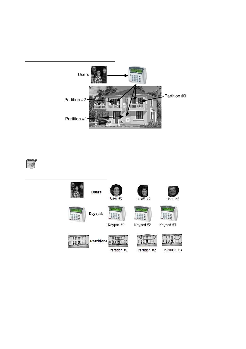
users are all assigned to all 3 partitions and can therefore control them all.
is divided into partitions, each controlled by a separate keypad. The users have
authorization levels based on partition/s, e.g., user 12 can only control Partition #3 & #14.
http://www.flickr.com/photos/axiomestates/3081558445/
HUNTER-PRO Series & CAPTAIN 8 User Guide
12.1.1 Examples
Example A: private premises, single keypad
Figure 2. Implementing partitions - Example A
• In this example, a single keypad controls all 3 partitions
• The
A user can control several partitions using a single code.
Example B: private premises, 3 keypads
27
5
Figure 3. Implementing partitions - Example B
• The system
• Every keypad displays the status of its assigned partitions only.
5
Published under ‘Creative Commons’ license (source:
)

28 HUNTER-PRO Series & CAPTAIN 8 User Guide
Example C: variable options6
Figure 4. Implementing partitions - Example C
• In a 3 floors building, the first floor is defined as Partition #1, the second as Partition
#2 and the third as Partition #3. There are 3 users and 3 keypads, with different
authorization levels:
User #2 is authorized to use all three keypads;
User #4 is authorized to use only keypad #1, which controls and displays partition
#2 only;
Users #1 & #2 are authorized to use only Keypad #2 which controls and displays all
3 partitions;
User #3 is authorized to use only keypad #3 which controls and displays partition
#3 only;
Example D: office compound
Figure 5. Implementing partitions - Example D
• A compound is made of 16 offices; each is located in a separate room. Each room is
assigned as a partition and can be controlled by different users, remote controls, key
switches and RFID tags.
• The single keypad in this example will display the status of all partitions, though the users
will only be able to control their authorized partition/s.
• A detector located at the entrance and allocated to all partitions protects the entrance, as
soon as all partitions are armed. This detector will be disarmed as soon as the first
partition is disarmed.
6
Published under Creative Commons license (source: http://awkwardfamilyphotos.com/wp-content/
uploads/2009/07/shari-awkward-plaid-family-photo.jpg)

HUNTER-PRO Series & CAPTAIN 8 User Guide 29
Example E: business installation
Figure 6. Common application for partitions
• The headquarters of a company is divided into 4 departments: each has its own keypad,
employees, working hours, etc.
• The employees (i.e. users) can have access only to their department/partition, or to several.
12.1.2 Displaying armed partitions
• The Installer can enable the displaying of the status of the partition.
• Armed partitions are displayed with “X”, above the corresponding number.
12.2 Arming with key, key fob or RFID tag/keychain
• You can arm your system using key switch, key fob and RFID tag/keychain.
• The three accessories are assigned per user.
• A key switch requires no other module and is used mostly in businesses.
• Key fobs require the installation of a wireless module, the I/O-WN that supports up to 24
key fobs. The module can be purchased from your Installer.
• RFID tags and key chains require the use of RFID keypad. The keypad can be purchased
from your Installer. Depending on your system model, up to 32/96/144 RFID users can
be supported.
12.2.1 Arming with a key fob
Figure 7. The MCT-234 key fob
The Visonic MCT-234 key fob has 4 push buttons. Pushing each button, or a combination of
two, performs the next actions:

Action
Push button/s
Arm to full mode
Arm to “Home 1” mode
Arm to “Home 2” mode
Disarm
Generate PANIC alarm
Trigger one of the system’s outputs (to
Keystrokes
Key 1 2 3 4 5 6 7 8
[1] . , ? ! 1
[2] A B C 2
[3] D E F 3
[4] G H I 4
[5] J K L 5
[6] M N O 6
30 HUNTER-PRO Series & CAPTAIN 8 User Guide
+
+
open a gate, turn on a spotlight, etc.)
Up to 24 key fobs can be assigned to users.
12.3 Enabling Remote Upload
• Your alarm system can be uploaded (i.e. programmed) remotely, by a service technician,
over the phone line or the network.
• For security reasons, this feature is disabled by default. If the technician needs to use it,
you have to approve it.
• To do so: just before the technician calls the system, enter the Master code (only the
ENTR
ENTR
Master code can enable it) and press twice.
ENTRENTR
12.4 Names and Characters
• Names and characters are entered the same way as in cell phones: each key has letters
and characters associated with it.
• A Username can have up to 8 characters.
• Each arming & disarming is registered in the memory log along with the user
name, date and time (see section 3).
• The number of keystrokes determines which character is selected.
• To enter some characters using the same key, wait 2 seconds between each keystroke.
• For example, key is used for typing the letters M, N, O and number 6. To select
“M”, press the key once; to select “O”, press the key three times.
• See the keys and their associated characters in the next table.
6666

Keystrokes
Key 1 2 3 4 5 6 7 8
[7] P Q R S 7
[8] T U V 8
[9] W X Y Z 9
[0] Space
0
[*] ( ) / * : - + #
[#] Uppercase/
Lowercase letters
(toggle)
Cancel/Return to previous screen without
[NEXT]
Next character
[BACK]
Previous character
[ENTR]
Select/Save
HUNTER-PRO Series & CAPTAIN 8 User Guide 31
[END]
saving
12.4.1 Example
• The following demonstrates writing the word “KITCHEN”:
Key Keystrokes Character
[5]
[4]
[8]
[2]
[4]
[3]
[6]
2 K
3 I
1 T
3 C
2 H
2 E
2 N
NE XT
NE XT
NE XTNE XT
NE XT
NE XT
NE XTNE XT
NE XT
NE XT
NE XTNE XT
NE XT
NE XT
NE XTNE XT
NE XT
NE XT
NE XTNE XT
NE XT
NE XT
NE XTNE XT
EN TR
EN TR
EN TREN TR
12.5 PANIC alarm
+
• To manually generate a PANIC alarm, press and hold for 2 seconds
(until a confirmation tone is sounded), the Asterisk and the Hash Keys.
• PANIC alarm is immediately reported to the Monitoring Station (if you
are a subscriber) and your phones.
• In addition to activating the sirens, the Installer can set the system to
response in various ways.
####
Nem jeleníthető meg a kép. Lehet, hogy nincs elegendő
memória a megnyitásához, de az sem kizárt, hogy sérült
a kép. Indítsa újra a számítógépet, és nyissa meg újból a
fájlt. Ha továbbra is a piros x ikon jelenik meg, törölje a
képet, és szúrja be ismét.
12.6 Resetting Smoke/Fire/Anti-mask detectors
• Smoke, Fire and Anti-mask detectors need to be reset if they are activated.
• They can be reset automatically or manually. To manually reset them:
and hold the hash key for 2 seconds, until a confirmation tone is sounded).
12.7 Turning the keypad chime ON/OFF
EN D
EN D ENT R
EN DEN D
+
ENT R
ENT RENT R
####
(press

Hunter
-
Pro
832 896 8144
Zones (8 basic)
32 96
144
Users 32 96 144
Partitions
16 16 16
Wireless zones
24 32 32
Key fobs
24 24 24
Memory total
500
500
999
Feature
Captain 8
Hunter
-
Pro
Zones (using expanders
16 96
Zone doubling (of the
√
Keypads
8 8
Partitions
4 16
EXP-PRO - √
I/O-8N/PS
1 11
I/O-16/PS - 5
Outputs
12
3 58
OUT-1000 - √
I/O-R 1 4
I/O-WN
√
√
Users 30 96
RFiD tags
30 96
VVR devices
1 4
Events Log
160
500
32 HUNTER-PRO Series & CAPTAIN 8 User Guide
• Pressing these keys together turns the keypad’s chime ON/OFF (toggle mode).
• Note that turning the chime off disables vocal indication of faults and opening Chime zones.
• The chime is set separately in each keypad.
E ND
E ND
• To silence the chime in case of faults,
E NDE N D
12.8 Comparison between the Hunter-Pro
Series models
Feature
of which non-volatile
250
250
512
12.9 Comparison between the Hunter-Pro 896 &
Captain 8
onboard zones)
of which onboard
Wireless zones
Key fobs
of which non-volatile
√
8
24
128
7
32
24
250
HUNTER-PRO Series & CAPTAIN 8 User Guide 33
13 MANUAL SYSTEM TESTS (BACK KEY)
Master code
Tes t i ng Li ne. . S1
Fi ni s hed OK!
Bat t er y Tes t . . Bat t er y Tes t . .
BACK
BACK
BACKBAC K
… …
Fi n i shed OK!
… .
• The system constantly tests the backup battery, the voltage and the phone line. However,
you can perform a manual test too.
• A manual test is reported to the Monitoring Station.
• If the tests fail, the following messages appear:
Bat t er y Test . .
Low Bat t er y!
If your alarm system is connected to a Monitoring Station via Ethernet or GPRS,
some additional test screens are displayed.
and/or
12 NOV 11 17: 15
Phone Li ne Faul t
14 REMOTE CONTROL VIA THE PHONE
• Remote control is not available in Captain 8.
• This section refers to Hunter-Pro Series only.
• The Hunter-Pro Series alarm system can be remotely controlled via any touchtone or
cellular phone.
• A remote control call can be initiated by both calling the panel and receiving a call
from the panel.
• There are two modes to remote control (they are set by the Installer):
Basic mode: includes arming, disarming, deactivating the sirens, and more. That’s
the default mode;
Full mode: includes the basic mode and in addition, activating RELAY switches.
14.1 Basic mode
• To control the system remotely:
1. Call the phone number to which the system is connected (or pick a call from the system).
2. Wait for a confirmation tone: a long tone followed by 2 beeps.
3. Dial the Master code or authorized User code (see section 9.4);
4. Wait for a status tone:
Continuous
Beeps: The system is armed;
: The system is disarmed;

34 HUNTER-PRO Series & CAPTAIN 8 User Guide
The system does not recognize phone commands (tones) while sounding
the confirmation tone. Therefore, you must wait until the confirmation
tone is over, before pressing any phone key.
5. Dial a number, according to the next table. The panel confirms every command
with two beeps.
Dial Action
0 Stop the external siren and the dialer
1 Arm the system
2 Disarm the system (if enabled by the technician)
4 Arm the system to “Home 1” mode
5 Switch on the onboard relay
6 Switch off the onboard relay
7 Arm the system to “Home 2” mode
8 Listen in for one minute (using MIC-200). Any more
press will extend the listen in time in one minute
• While the system is communicating, the message “Other keypad in use” is
displayed on all the keypads.
• If the panel does not receive any command for a period of 60 seconds, it
disconnects the call. It then remains in standby mode (with the above
message displayed on the keypads) for another 60 seconds, before the
message disappears.
• During listen in, all other remote control commands are disabled.
14.2 Full mode
• To control the panel in full mode:
1. Repeat steps 1-4 in the previous Basic mode section.
2. To trigger an output, press [*] and the corresponding command, as listed in the
following tables.
3. To deactivate an output, press [#] and the corresponding command from the
following tables.
Command Dial
Turn off the external
siren and stop the dialer
Arm the system
Disarm the system #01
Arm to “Home 1” mode *04
Arm to “Home 2” mode *07
Start listen in for 1 min. *08
General
*
*
00
01
System’s outputs
Output Dial
Ext. SIREN 11
Int. SIREN 12
RELAY 13
SMOKE 14
ON/OFF 15
ALARM 16
AUDIO Ctrl 17

HUNTER-PRO Series & CAPTAIN 8 User Guide 35
RELAYs on I/O-8N
zone expanders
I/O-8N Dial
1 31
2 32
3 33
4 34
5 35
6 36
7 37
8 38
9 39
10 40
11 41
12 42
13 43
14 44
15 45
16 46
Send SMS message
with the system status
to your phones
Phone no. Dial
1 91
2 92
3 93
4 94
I/O-R RELAY expanders
Expander no. 1 Expander no. 3
RELAY no. Dial RELAY no. Dial
1 51 1 67
2 52 2 68
3 53 3 69
4 54 4 70
5 55 5 71
6 56 6 72
7 57 7 73
8 58 8 74
Expander no. 2 Expander no. 4
RELAY no. Dial RELAY no. Dial
1 59 1 75
2 60 2 76
3 61 3 77
4 62 4 78
5 63 5 79
6 64 6 80
7 65 7 81
8 66 8 82
14.2.1 Examples
Activate the ‘Ext. SIREN’ output:
Dial the panel’s phone number the panel picks up the call wait for the confirmation tone
to end dial the Master code wait for command confirmation tone to end dial *11
Deactivate RELAY#2 in I/O-R #2:
Dial the panel’s phone number the panel picks up the call wait for the confirmation tone
to end dial the Master code wait for command confirmation tone to end dial #60.

36 HUNTER-PRO Series & CAPTAIN 8 User Guide
15 TROUBLESHOOTING
• Faults are indicated by the flashing red LED in the keypad, a description of the fault is
displayed, the buzzer sounds beeps and the system logs it. In addition, the service
technician can set the system to report it to the Central Monitoring Station, to send an
alert by the telephone, to trigger an output and more.
• If more than a single fault occurs, the display will scroll between them.
• Unless instructed otherwise, call a service technician when the system reports on faults.
Fault Description and troubleshoot
Low Battery
Mains Fault Appears during a power failure.
Clock Not Set
Phone Line Fault
Tamper 1
Tamper 2 Tamper switch 2 is open.
Expander X Tamper Expander X’s box or tamper is open.
Expander X Fault Expander X is faulty.
EXP X Voltage Low voltage to the I/O-8N zone expander.
Expander X Mains Expander X has no Mains voltage.
Expander X Batt Expander X has low battery fault.
Keypad X Tamper Keypad X’s tamper switch is open.
Low Voltage
Wireless Z Fault A wireless detector (zone) is faulty (no supervision signal).
MS COM Fault Failure to communicate with the Central Monitoring Station over the phone.
KEYPAD NOT CONNECTED No communication between the keypad and the control panel.
GSM Unit Fault The GSM-200 module cannot be detected or is faulty.
GSM Link Fault GSM limited or no reception.
GSM Comm. Fault GSM communication failure with Central Monitoring Station #1.
GSM Comm. 2 Fault GSM communication failure with Central Monitoring Station #2.
SIM Card Fault SIM card is not detected or is faulty.
Wireless System I/O-WN module cannot be detected or is faulty.
W/L Unit Tamper I/O-WN box tamper is open or faulty.
Other keypad in use Other keypad is in use or the system is remotely controlled via the telephone.
Check Keypad Number The keypad’s ID is not configured properly.
Keypad X Fault Keypad X is faulty.
Zone Fault A zone (include. Wireless zone) is tampered or faulty. Possible tampering!
Occurs after a prolonged power failure or when the battery is outdated. If the
fault lasts more than one day, or there was no previous power failure, call a
service technician.
Appears following a prolonged power failure during which the backup battery
was completely discharged. Set time and date (see page 20).
Perform phone line test (see Manual System
other telephone appliance is using the line. If the fault persists, call a service
technician.
Tamper switch 1 is open.
Appears before the backup battery is completely discharged, usually during a
prolonged power failure. Call a service technician immediately!
Tests
on page 34). Make sure no

HUNTER-PRO Series & CAPTAIN 8 User Guide 37
Fault Description and troubleshoot
Detec Vol. Fault
SMS Com. Failure SMS communication fault.
Install SMS Unit No SMS unit is detected or the unit is faulty.
Network Fault Network communication with the Central Monitoring Station is faulty.
IO-R X Fault The I/O-R relay expander is faulty.
IO-R X Tamper The I/O-R relay expander tamper is open.
IO-R X Voltage Low voltage in the I/O-R relay expander.
IO-R X Mains IO-R X has no Mains voltage.
IO-R X Batt IO-R X has low battery.
Wireless Jamming The wireless receiver (I/O-WN) is jammed.
Supervision A wireless detector “life signal” has not been received.
Int. siren fault The internal siren is faulty.
Ext. siren fault The external siren is faulty.
Video X fault Communication fault between the panel and the video unit VVR #X.
Video X power fault Voltage fault in VVR #X.
net4pro fault Communication fault between the panel and the net4pro network card.
Detector voltage is faulty due to possible tampering. Call a service technician
immediately!

38 HUNTER-PRO Series & CAPTAIN 8 User Guide
16 APPENDIX: ZONE LOCATION TABLE
No. Zone Location
1.
2.
3.
4.
5.
6.
7.
8.
9.
10.
11.
12.
13.
14.
15.
16.
17.
18.
19.
20.
21.
22.
23.
24.
25.
26.
27.
28.
29.
30.
31.
32.
33.
34.
35.
36.
37.
38.
39.
40.
41.
42.
43.
44.
No. Zone Location
45.
46.
47.
48.
49.
50.
51.
52.
53.
54.
55.
56.
57.
58.
59.
60.
61.
62.
63.
64.
65.
66.
67.
68.
69.
70.
71.
72.
73.
74.
75.
76.
77.
78.
79.
80.
81.
82.
83.
84.
85.
86.
87.
88.

HUNTER-PRO Series & CAPTAIN 8 User Guide 39
No. Zone Location
89.
90.
91.
92.
93.
94.
95.
96.
97.
98.
99.
100.
101.
102.
103.
104.
105.
106.
107.
108.
109.
110.
111.
112.
113.
114.
115.
116.
117.
No. Zone Location
118.
119.
120.
121.
122.
123.
124.
125.
126.
127.
128.
129.
130.
131.
132.
133.
134.
135.
136.
137.
138.
139.
140.
141.
142.
143.
144.
Installer Details:
Name: ________________________ Phone: ____________________________
Cellular: ___________________________
Company: _________________________________________________________
Phone no.: _________________________
Date of installation: Day _____ Month _____ Year _______
End of service: Day _____ Month _____ Year _______

40 HUNTER-PRO Series & CAPTAIN 8 User Guide
PIMA Electronic Systems Ltd. does not represent that its product may not be compromised and/or
circumvented, or that the Product will prevent any death, personal and/or bodily injury and/or damage to
property resulting from burglary, robbery, fire or otherwise, or that the Product will in all cases provide
adequate warning or protection. The User understands that a properly installed and maintained equipment
may only reduce the risk of events such as burglary, robbery, and fire without warning, but it is not
insurance or a guarantee that such will not occur or that there will be no death, personal damage and/or
damage to property as a result.
PIMA Electronic Systems Ltd. shall have no liability for any death, personal and/or bodily injury and/or
damage to property or other loss whether direct, indirect, incidental, consequential or otherwise, based on
a claim that the Product failed to function.
Please refer to a separate warranty statement found on PIMA website at:
http://www.pima-alarms.com/site/Content/t1.asp?pid=472&sid=57
Warning: The user should follow the installation and operation instructions and among other things test
the Product and the whole system at least once a week. For various reasons, including, but not limited to,
changes in environment conditions, electric or electronic disruptions and tampering, the Product may not
perform as expected. The user is advised to take all necessary precautions for his/her safety and the
protection of his/her property.
This document may not be duplicated, circulated, altered, modified, translated, reduced to any form or
otherwise changed; unless PIMA’s prior written consent is granted.
All efforts have been made to ensure that the content of this manual is accurate. Pima retains the right to
modify this manual or any part thereof, from time to time, without serving any prior notice of such
modification.
Please read this manual in its entirety before attempting to program or operate your system. Should you
misunderstand any part of this manual, please contact the supplier or installer of this system.
Copyright 2011 PIMA Electronic Systems Ltd. All rights reserved.
PIMA Electronic Systems Ltd.
5 Hatzoref Street, Holon 58856, Israel
Tel: +972.3.6506414
Fax: +972.3.5500442
Email: support@pima-alarms.com
Web: http://www.pima-alarms.com
Partner’s website: http://www.pima-alarms.com/site/modules/login.asp
4410280
*4410280*
Version : B2, XX en, September 2011
 Loading...