

Page 1
E-STOP relays, safety gate monitors
Category 4, EN 954-1
PNOZ 2VQ
Safety relay for monitoring E-STOP
pushbuttons and safety gates.
Approvals
PNOZ 2VQ
Unit features
` Positive-guided relay outputs:
– 3 safety contacts (N/O), instanta-
neous
– 2 safety contacts (N/O), delay-on
de-energisation
– 1 auxiliary contact (N/C), instan-
taneous
` Connection options for:
– E-STOP pushbutton
– Safety gate limit switch
– Reset button
` Delay-on de-energisation can be
set separately for both safety contacts with delay-on de-energisation
` Delay time can be cancelled via re-
set button
` LED indicator for:
– Switch status channel 1/2
– Supply voltage
Unit description
The safety relay meets the requirements of EN 60204-1 and IEC 602041 and may be used in applications with
` E-STOP pushbuttons
` Safety gates
The max. category the safety contacts
can achieve in accordance with EN
954-1 is stated in the technical details.
Safety features
The relay conforms to the following
safety criteria:
` The circuit is redundant with built-in
self-monitoring.
` The safety function remains effecti-
ve in the case of a component failure.
` The correct opening and closing of
the safety function relays is tested
automatically in each on-off cycle.
` The unit has an electronic fuse.
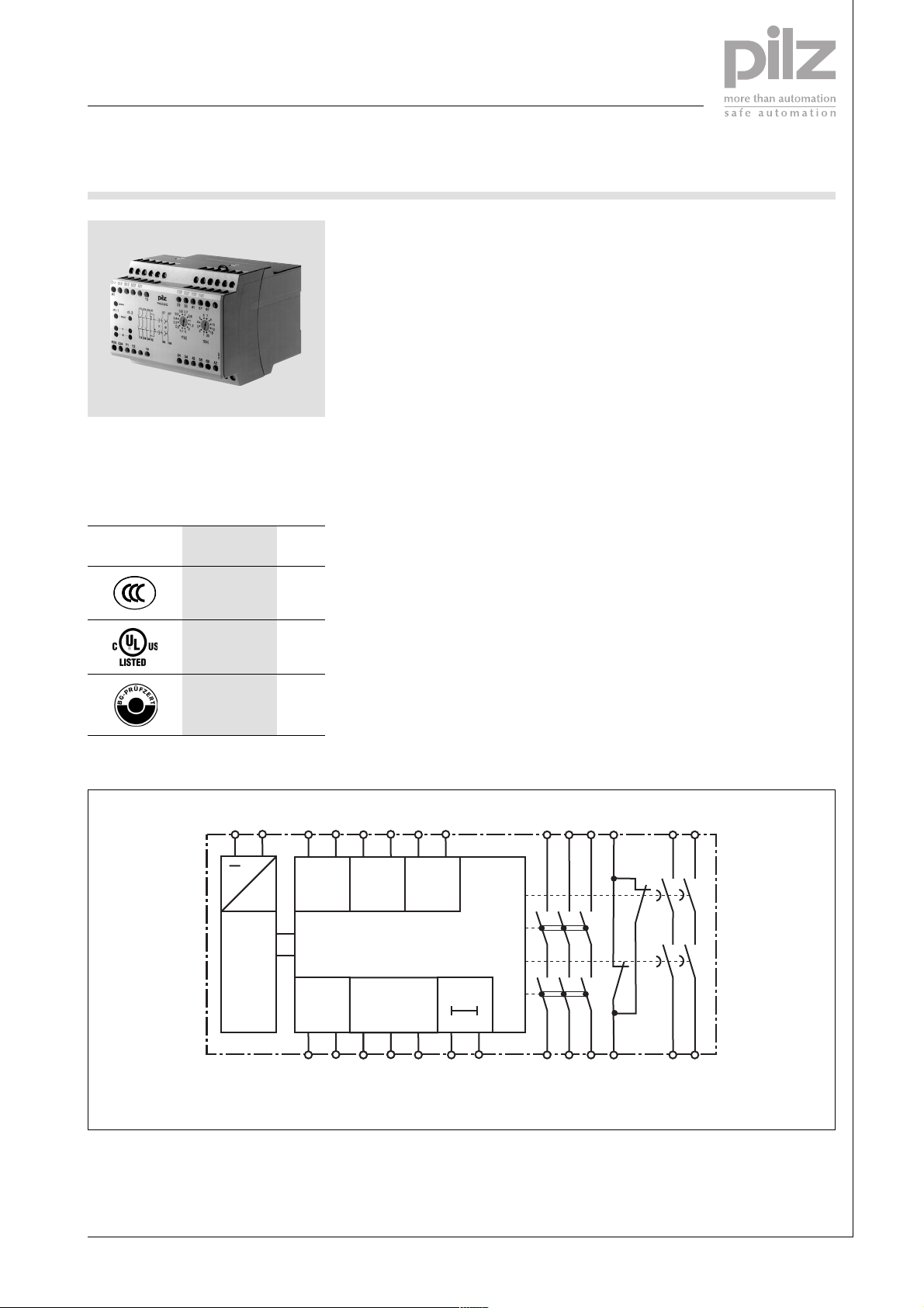
Block diagram
A1 A2
~
Power
Power
=
S11 S12
Feed-
back
Y1 Y2
S21 S22
InputInput
Reset/
Start
S12 S33
Y36 S52
Input
S34
Y39 Y40
Reset
t
K3
K1
K4
K2
13 23 33
14 24 34
41
42
57 67
58 68
Pilz GmbH & Co. KG, Sichere Automation, Felix-Wankel-Straße 2, 73760 Ostfildern, Germany
Telephone: +49 711 3409-0, Telefax: +49 711 3409-133, E-Mail: [email protected]
NSG-D-2-063-01/05
Page 2
E-STOP relays, safety gate monitors
Category 4, EN 954-1
PNOZ 2VQ
Function description
` Single-channel operation: no red-
undancy in the input circuit, earth
faults in the reset and input circuit
are detected.
` Dual-channel operation without de-
tection of shorts across contacts:
redundant input circuit, detects
– earth faults in the reset and input
circuit,
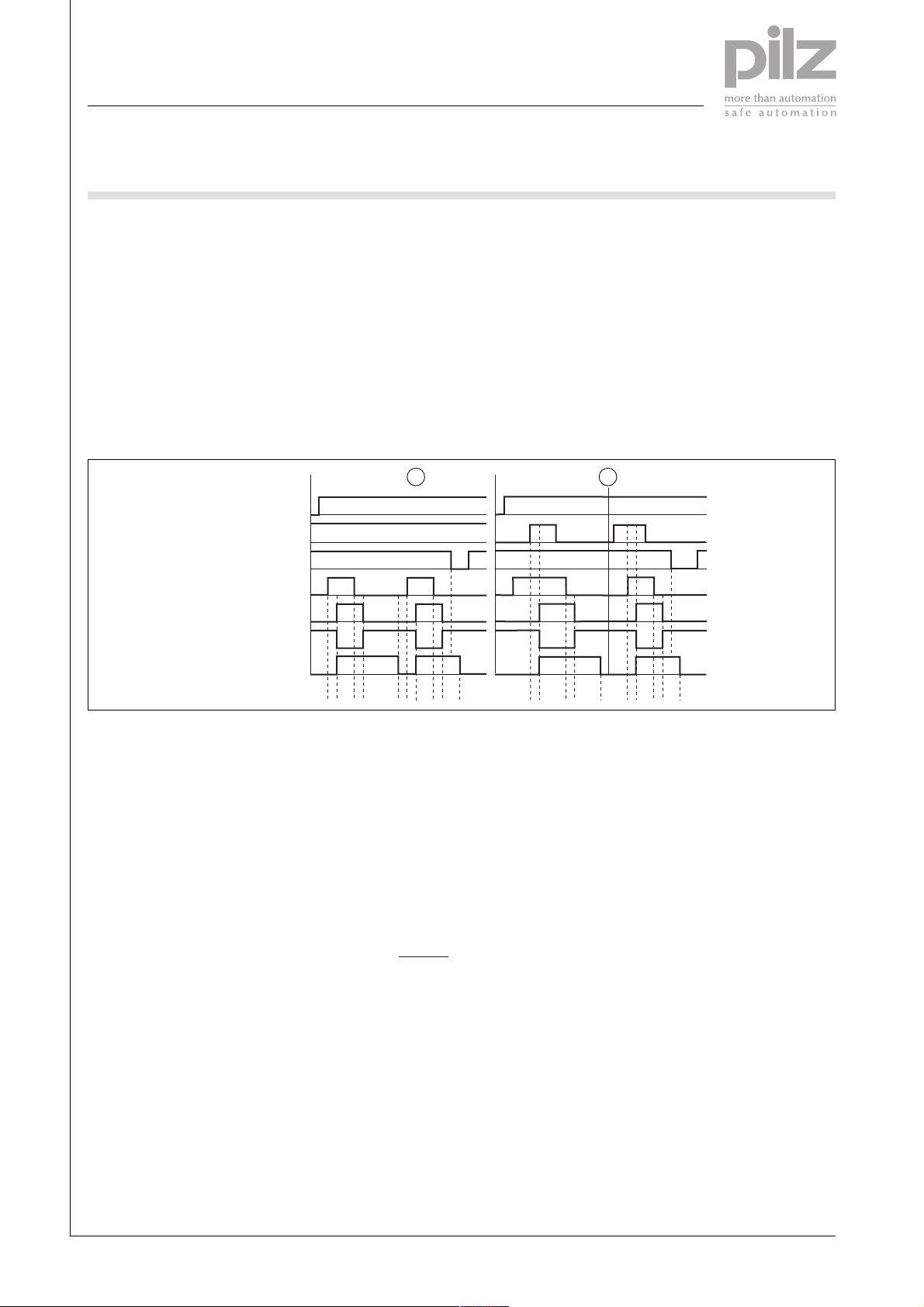
Timing diagram
POWER
Reset/Start
Reset t
v
Input
Output safe
Output aux
Output safe del
– short circuits in the input circuit
and, with a monitored reset, in
the reset circuit too.
` Dual-channel operation with detec-
tion of shorts across contacts: redundant input circuit, detects
– earth faults in the reset and input
circuit,
– short circuits and shorts bet-
ween contacts in the input circuit.
1 2
t1 t2 t3 t2
t1
t3
t1
` Automatic start: Unit is active once
the input circuit has been closed.
` Manual reset: Unit is active once
the input circuit is closed and then
the reset circuit is closed.
` Increase in the number of available
contacts by connecting contact expander modules or external contactors/relays.
ab
t2
t2t1t3 t3
Key
` Power: Supply voltage
` Reset/start: Reset circuit S12, S33,
S34
` Reset t
: Y39-Y40
v
` Input: Input circuits S11-S12, S21-
S22, Y36-S52
` Output safe: Safety contacts 13-14,
23-24, 33-34
Wiring
Please note:
` Information given in the “Technical
details” must be followed.
` Outputs 13-14, 23-24, 33-34 are in-
stantaneous safety contacts, outputs 57-58, 67-68 are delay-on deenergisation safety contacts, output 41-42 is an instantaneous auxiliary contact (e.g. for display).
` To prevent contact welding, a fuse
should be connected before the
output contacts (see technical details).
` Calculation of the max. cable runs
in the input circuit:
l
max
` Output safe del: Safety contacts,
delayed 57-58, 67-68
` Output aux: Auxiliary contacts 41-
42
` c: Automatic reset
` d: Manual reset
` a: Input circuit closes before reset
circuit
R
lmax
=
I
max
Rl / km
R
= max. overall cable resi-
lmax
stance (see technical details)
/km = cable resistance/km
R
l
` Use copper wire that can withstand
60/75 °C.
` Sufficient fuse protection must be
provided on all output contacts with
capacitive and inductive loads.
` b: Reset circuit closes before input
circuit
: Switch-on delay
` t
1
` t2: Delay-on de-energisation inst.
contacts
: Delay time
` t
3
Telephone: +49 711 3409-0, Telefax: +49 711 3409-133, E-Mail: [email protected]
NSG-D-2-063-01/05Pilz GmbH & Co. KG, Sichere Automation, Felix-Wankel-Straße 2, 73760 Ostfildern, Germany
-2
Page 3
E-STOP relays, safety gate monitors
Category 4, EN 954-1
PNOZ 2VQ
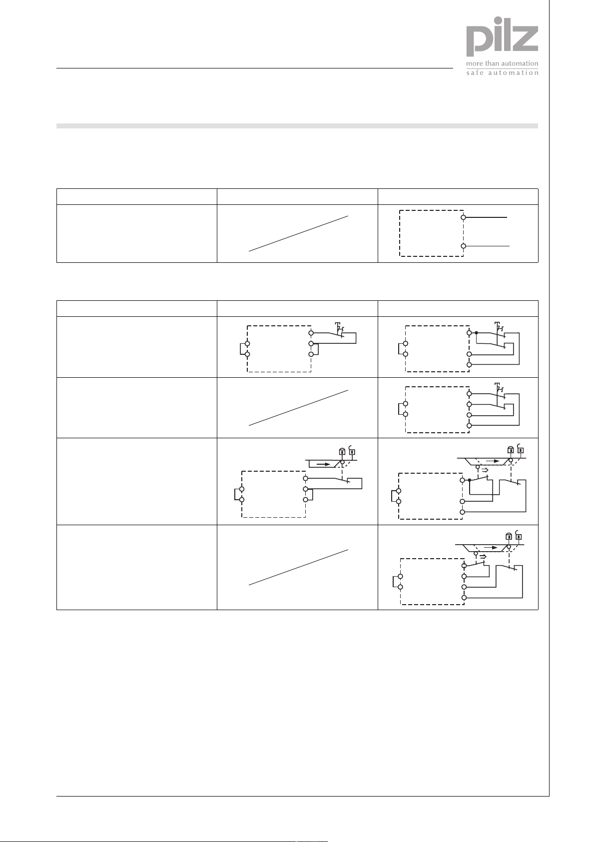
Preparing for operation
` Supply voltage
Supply voltage AC DC
` Input circuit
Input circuit Single-channel Dual-channel
E-STOP
without detection of shorts across
contacts
S21
S22
S11
S12
S52
S1
S21
S22
E-STOP
with detection of shorts across contacts
Y36
S52
Safety gate
without detection of shorts across
contacts
S21
S22
S11
S12
S52
S1
S21
S22
S11
S12
S52
A1
A2
S11
S21
S22
S12
S11
S12
S52
S1
L+
L-
S1
S1
S2
Safety gate
with detection of shorts across contacts
Pilz GmbH & Co. KG, Sichere Automation, Felix-Wankel-Straße 2, 73760 Ostfildern, Germany
Telephone: +49 711 3409-0, Telefax: +49 711 3409-133, E-Mail: [email protected]
Y36
S52
S11
S12
S21
S22
S1
NSG-D-2-063-01/05
S2
Page 4
E-STOP relays, safety gate monitors
Category 4, EN 954-1
PNOZ 2VQ
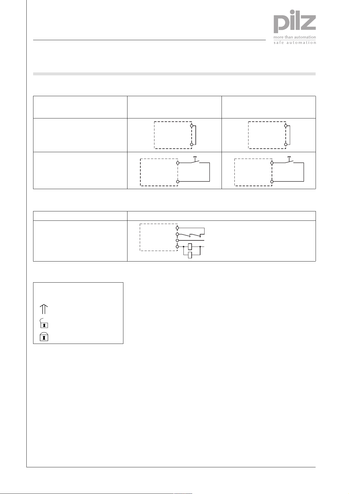
` Reset circuit
Reset circuit E-STOP/safety gate wiring (single-
channel and dual-channel without
shorts across contacts)
Automatic reset
Manual reset
S33
S34
S3
S33
S34
` Feedback loop
Feedback loop
Contacts from external contactors
Y1
Y2
13 (23 ... 67)
14 (24 ... 68)
K5
K6
K5
K6
E-STOP/safety gate wiring (dualchannel with shorts across contacts)
S12
S34
S3
S12
S34
L1
N
` Key
S1/S2
E-STOP pushbutton/ safety
gate switch
S3 Reset button
Switch operated
Gate open
Gate closed
Telephone: +49 711 3409-0, Telefax: +49 711 3409-133, E-Mail: [email protected]
NSG-D-2-063-01/05Pilz GmbH & Co. KG, Sichere Automation, Felix-Wankel-Straße 2, 73760 Ostfildern, Germany
-4
Page 5
E-STOP relays, safety gate monitors
Category 4, EN 954-1
PNOZ 2VQ
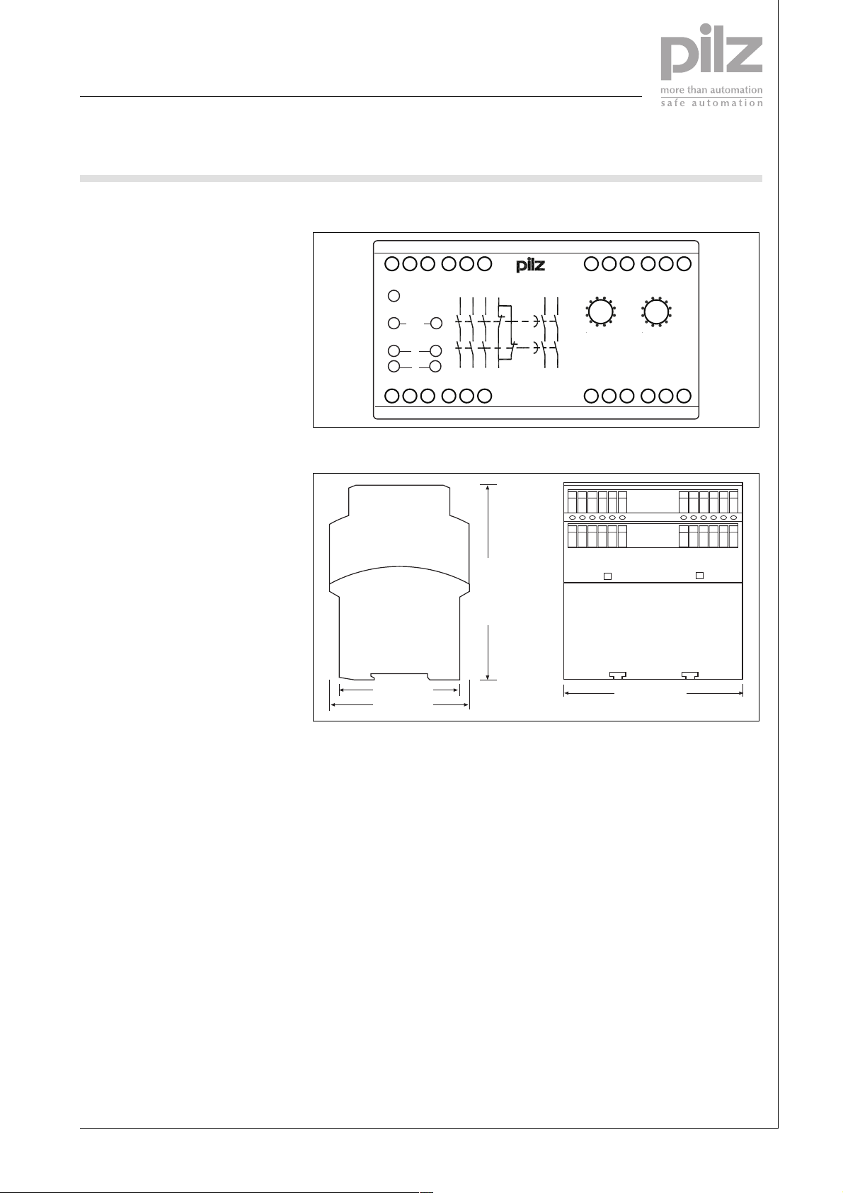
Terminal configuration
S11
S12 S12 S22 S21 Y36 S52 Y39 Y40
Installation
` The safety relay should be installed
in a control cabinet with a protection type of at least IP54.
` Use the notch on the rear of the unit
to attach it to a DIN rail.
` Ensure the unit is mounted securely
on a vertical DIN rail (35 mm) by
using a fixing element (e.g. retaining
brakket or an end angle).
Dimensions
1
power
ch. 1
ch. 2
3 9
Input
t1
5 11
t2
128
S33 S34 Y1 Y2 14
23 33 41 57 67
13
24 34
14
13
42
121 (4.76")
PNOZ 2VQ
23 33 41 57 67A1
0,6 0,7
0,5
0,4
0,3
0,2
t1[s]
58 68
24 34 42 58 68 A2
67
8
5
0,8
1
1,5
2
30,1
10
4
12
3
15
2
201
t2[s]
18 603
75 (2.95")
87 (3.42")
112,5 (4.41")
Pilz GmbH & Co. KG, Sichere Automation, Felix-Wankel-Straße 2, 73760 Ostfildern, Germany
Telephone: +49 711 3409-0, Telefax: +49 711 3409-133, E-Mail: [email protected]
NSG-D-2-063-01/05
Page 6
E-STOP relays, safety gate monitors
Category 4, EN 954-1
PNOZ 2VQ
Notice
This data sheet is only intended for use
during configuration. For installation
and operation, please refer to the operating instructions supplied with the
unit.
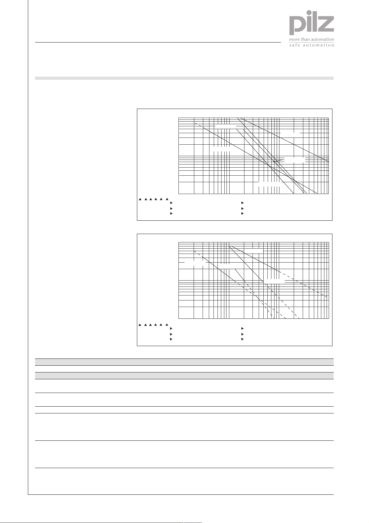
Service life graph
Instantaneous safety contacts:
10
1
D Nennbetriebstrom (A)
GB Nominal operating current (A)
F Courant coupé (A)
0.1
E Corriente nominal de servicio (A)
I Corrente di esercizio nominale (A)
NL Nominale bedrijfsstroom (A)
10 100 1000 10000
D Schaltspielzahl x 10
GB Cycles x 10
F Nombre de manvres x 10
3
Delayed safety contacts:
10
DC13: 24 V
AC1: 230 V
DC13: 24 V
3
AC15: 230 V
DC1: 24 V
AC1: 400 V
AC15: 230 V
E Número de ciclos x 10
I Numero dei cicli di commutazione x 10
3
NL Aantal schakelingen x 10
DC1: 24 V
3
3
3
1
D Nennbetriebstrom (A)
GB Nominal operating current (A)
0.1
F Courant coupé (A)
E Corriente nominal de servicio (A)
I Corrente di esercizio nominale (A)
NL Nominale bedrijfsstroom (A)
10 100 1000 10000
D Schaltspielzahl x 10
GB Cycles x 10
F Nombre de manvres x 10
3
3
E Número de ciclos x 10
I Numero dei cicli di commutazione x 10
3
NL Aantal schakelingen x 10
Technical details
Electrical data
Supply voltage
Supply voltage U
DC 24 V
B
Voltage tolerance -15 %/+10 %
Power consumption at U
DC 6.5 W
B
Residual ripple DC 160 %
Voltage and current at
input circuit DC: 24.0 V 35.0 mA
reset circuit DC: 24.0 V 100.0 mA
feedback loop DC: 24.0 V 100.0 mA
Output contacts in accordance with EN 954-1 Category 4 Safety contacts (N/O): 3
Output contacts in accordance with EN 954-1 Safety contacts (N/O), delayed: 2
Category 3 Delay time <30 s
Auxiliary contacts (N/C): 1
AC1: 230 V
3
3
3
Telephone: +49 711 3409-0, Telefax: +49 711 3409-133, E-Mail: [email protected]
NSG-D-2-063-01/05Pilz GmbH & Co. KG, Sichere Automation, Felix-Wankel-Straße 2, 73760 Ostfildern, Germany
-6
Page 7
E-STOP relays, safety gate monitors
Category 4, EN 954-1
PNOZ 2VQ
Electrical data
Utilisation category in accordance with EN 60947-4-1
Safety contacts: AC1 at 240 V I
Safety contacts: AC1 at 400 V I
Safety contacts: DC1 at 24 V I
Safety contacts, delayed: AC1 at 240 V I
Safety contacts, delayed: DC1 at 24 V I
Auxiliary contacts: AC1 at 240 V I
Auxiliary contacts: DC1 at 24 V I
Utilisation category in accordance with EN 60947-5-1
Safety contacts: AC15 at 230 V I
Safety contacts: DC13 at 24 V (6 cycles/min) I
Safety contacts, delayed: AC15 at 230 V I
Safety contacts, delayed: DC13 at 24 V (6 cycles/min) I
Auxiliary contacts: AC15 at 230 V I
Auxiliary contacts: DC13 at 24 V (6 cycles/min) I
Contact material AgSnO2 + 0.2 µm Au
External contact fuse protection to EN 60947-5-1
Blow-out fuse, quick
Safety contacts: 10 A
Safety contacts, delayed: 6 A
Auxiliary contacts: 10 A
Blow-out fuse, slow
Safety contacts: 6 A
Safety contacts, delayed: 4 A
Auxiliary contacts: 6 A
Circuit breaker 24 VAC/DC, characteristic B/C
Safety contacts: 6 A
Safety contacts, delayed: 4 A
Auxiliary contacts: 6 A
Max. overall cable resistance R
single-channel at U
DC 60 Ohm
B
dual-channel without detect. of shorts across contacts at U
dual-channel with detect. of shorts across contacts at U
input circuits, reset circuits
lmax
DC 120 Ohm
B
DC 5 Ohm
B
Times
Switch-on delay
with automatic reset typ. 200 ms
with automatic reset max. 300 ms
with automatic reset after power on typ. 200 ms
with automatic reset after power on max. 300 ms
with manual reset typ. 200 ms
with manual reset max. 300 ms
Delay-on de-energisation
with E-STOP typ. 15 ms
with E-STOP max. 30 ms
with power failure typ. 30 ms
with power failure max. 40 ms
Recovery time at max. switching frequency 1/s
after E-STOP 50 ms +tv
after power failure 100 ms
: 0.01 A , I
min
: 2,000 VA
P
max
: 0.01 A , I
min
P
: 2,000 VA
max
: 0.01 A , I
min
P
: 200 W
max
: 0.01 A , I
min
: 1,000 VA
P
max
: 0.01 A , I
min
P
: 100 W
max
: 0.01 A , I
min
P
: 2,000 VA
max
: 0.01 A , I
min
: 200 W
P
max
: 5.0 A
max
: 7.0 A
max
: 4.0 A
max
: 4.0 A
max
: 5.0 A
max
: 7.0 A
max
max
max
max
max
max
max
max
: 8.00 A
: 5.00 A
: 8.0 A
: 4.0 A
: 4.0 A
: 8.0 A
: 8.0 A
Pilz GmbH & Co. KG, Sichere Automation, Felix-Wankel-Straße 2, 73760 Ostfildern, Germany
Telephone: +49 711 3409-0, Telefax: +49 711 3409-133, E-Mail: [email protected]
NSG-D-2-063-01/05
Page 8
E-STOP relays, safety gate monitors
Category 4, EN 954-1
PNOZ 2VQ
Times
Delay time tV: selectable 0.10 s; 0.20 s; 0.30 s; 0.40 s; 0.50 s; 0.60 s; 0.70 s; 0.80 s; 1.00 s;
1.50 s; 2.00 s; 3.00 s Order no.: 774013
Delay time tv2: selectable 1.00 s, 2.00 s, 3.00 s, 4.00 s, 5.00 s, 6.00 s, 7.00 s, 8.00 s, 10.00
s, 12.00 s, 15.00 s, 20.00 s
Repetition accuracy 2 %
Time accuracy -15 %/+15 % +50 ms
Simultaneity, channel 1 and 2 150 ms
Supply interruption before de-energisation 20 ms
Environmental data
EMC EN 60947-5-1, EN 61000-6-2
Vibration in accordance with EN 60068-2-6
Frequency 10 - 55 Hz
Amplitude 0.35 mm
Climatic suitability EN 60068-2-78
Airgap creepage VDE 0110-1
Ambient temperature -10 - 55 °C
Storage temperature -40 - 85 °C
Protection type
Mounting (e.g. control cabinet) IP54
Housing IP40
Terminals IP20
Mechanical data
Housing material
Housing PPO UL 94 V0
Front ABS UL 94 V0
Max. cross section of external conductors with screw terminals
1 core flexible 0.20 - 4.00 mm² , 24 - 10 AWG
2 core, same cross section, flexible:
with crimp connectors, without insulating sleeve 0.20 - 2.50 mm² , 24 - 14 AWG
without crimp connectors or with TWIN crimp connectors 0.20 - 2.50 mm² , 24 - 14 AWG
Torque setting with screw terminals 0.60 Nm
Dimensions
Height 87.0 mm
Width 112.5 mm
Depth 121.0 mm
Weight 600 g
The standards current on 06/02 apply.
Max. continuous current
Number of contacts I
1 8.00 A
2 6.80 A
3 5.50 A
4 5.00 A
5 4.50 A
Order reference
Type Features Terminals Order no.
PNOZ 2VQ 24 VDC Screw terminals 774 013
Telephone: +49 711 3409-0, Telefax: +49 711 3409-133, E-Mail: [email protected]
(A) at UBDC
max
NSG-D-2-063-01/05Pilz GmbH & Co. KG, Sichere Automation, Felix-Wankel-Straße 2, 73760 Ostfildern, Germany
-8
 Loading...