

Page 1
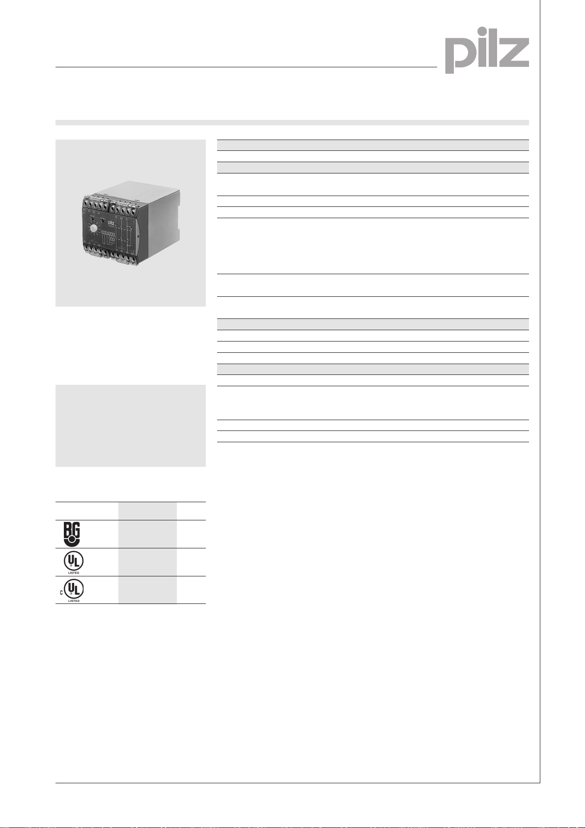
Expander Modules
Delayed
PZE 3V
Expander module in accordance with
VDE 0113-1, 11/98, EN 60204-1,
12/97 and IEC 204-1, 11/98 to
increase the number of safety
contacts available.
Features
l Delay-on de-energisation can be
set via the rotary switch
l Delay-on de-energisation is not
effective after power failure
Technical Details PZE 3V
Electrical Data
Supply Voltage AC: 24, 48, 110, 120, 230, 240 V
DC: 24 V
Tolerance 85 ... 110 %
Power Consumption Approx. 3.5 W/5 VA
Switching Capability in accordance with
EN 60947-4-1, 10/91 AC1: 240 V/6 A/1500 VA
DC1: 24 V/6 A/150 W
EN 60947-5-1, 10/91 AC15: 230 V/4 A; DC13: 24 V/3A
(DC13: 6 cycles/min.)
Output Contacts 2 safety contacts (N/O),
1 auxiliary contact (N/C)
Contact Fuse Protection 6 A quick or 4 A slow
(EN 60947-5-1, 10/91)
Times
Delay-on Energisation AC: approx. 75 ms, DC: approx. 20 ms
Delay-on De-energisation (range 0 ... 22 s) 0/2/4/6/8/10/12/14/16/18/20/22 s
Recovery Time Approx. 1.5 s
Mechanical Data
Torque Setting on Connection Terminals 1.2 Nm (screws)
Maximum Cross Section of 2 x 2.5 mm
External Conductors Single-core or multi-core with
crimp connectors
Dimensions (H x W x D) 87 x 90 x 110 mm
Weight AC: 520 g, DC: 470 g
Description
2
Approvals
PZE 3V
l
pending
pending
l 90 mm, P-75 housing, DIN-Rail
mounting
l Positive-guided relay outputs,
delay-off:
– 2 safety contacts (N/O)
– 1 auxiliary contact (N/C)
l LEDs for channel 1 and channel 2
l Connection for feedback control
loop.
Function Description
PZE 3V is used to increase
the number of safety contacts
available and the timed delay
switching of an E-STOP command
for
l E-STOP relays
l Safety gate monitors
l Two-hand relays
All base units must have a feedback
control loop.
6
NSG-D-2-095-01/01
Page 2
Expander Modules
Delayed
PZE 3V
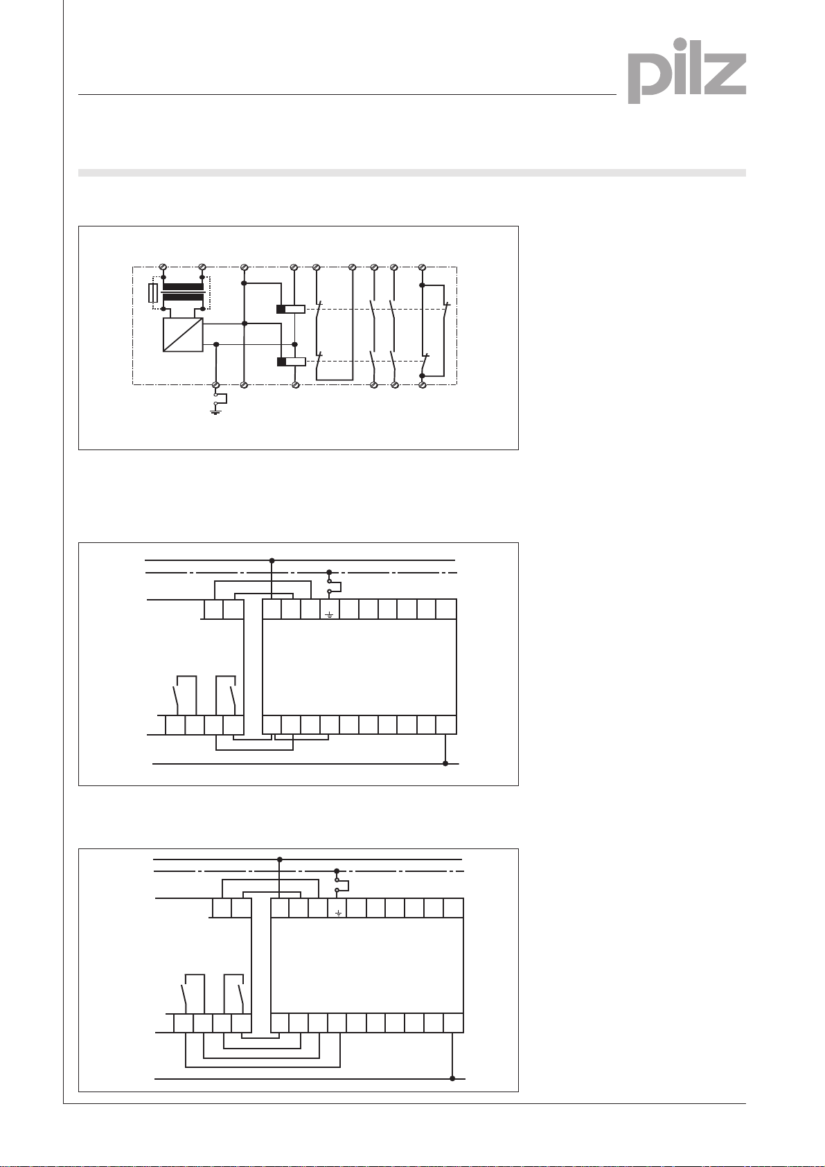
Internal Wiring Diagram
U
B
A1
(L+)
F1
G1
A2
(L-)
~
=
External Wiring
l Example 1
Single-channel operation
L1
PE
X2
(Y2)
+
X1
(Y1)
Input circuit
U
K1
K2
U
Input circuit
A1 Y1
Feedback
control
Y1
K1
K2
Y2
loop
(-)
Y2
Safety
contacts
13 23
14
Auxiliary
contact
31
24
32
1314232431
6
Base unit
23
24
N
l Example 2
Dual-channel operation
L1
PE
Base unit
23
24
PZE 3V
A2
14
13
X2
X1
(Y2)
(Y1)
K1K2U
A1
U
(-)
Y2
Y1
32
131423
PZE 3V
A2
K1K2U
U
13
14
243132
N
NSG-D-2-095-01/01
Page 3

Expander Modules
Delayed
PZE 3V
General Technical Data
Unless stated otherwise in the technical details for the specific unit
Electrical Data
Frequency Range AC 50 ... 60 Hz
Residual Ripple DC 160 %
Contact Material AgSnO
Continuous Duty 100 %
Environmental Data
EMC EN 50081-1, 01/92, EN 50082-2, 03/95
Vibration in accordance with Frequency: 10 ... 55 Hz,
EN 60068-2-6, 04/95 Amplitude: 0.35 mm
Climatic Suitability DIN IEC 60068-2-3, 12/86
Airgap Creepage DIN VDE 0110 part 1, 04/97
Ambient Temperature -10 ... +55 °C
Storage Temperature -40 ... +85 °C
Mechanical Data
Torque Setting on Connection Terminals 0.6 Nm (screws)
Mounting Position Any
Housing Material Thermoplast Noryl SE 100
Protection Mounting: IP 54
2
Housing: IP 40
Terminal Range: IP 20
The units were tested in accordance with the relevant standards current at
the time of development.
Order References
Type t U
PZE 3V 22 s 24 V DC 474 200
PZE 3V 22 s 24 V AC 474 202
PZE 3V 22 s 48 V AC 474 206
PZE 3V 22 s 110 V AC 474 210
PZE 3V 22 s 120 V AC 474 214
PZE 3V 22 s 230 V AC 474 218
PZE 3V 22 s 240 V AC 474 220
B
Order No.
6
NSG-D-2-095-01/01
 Loading...