

Page 1
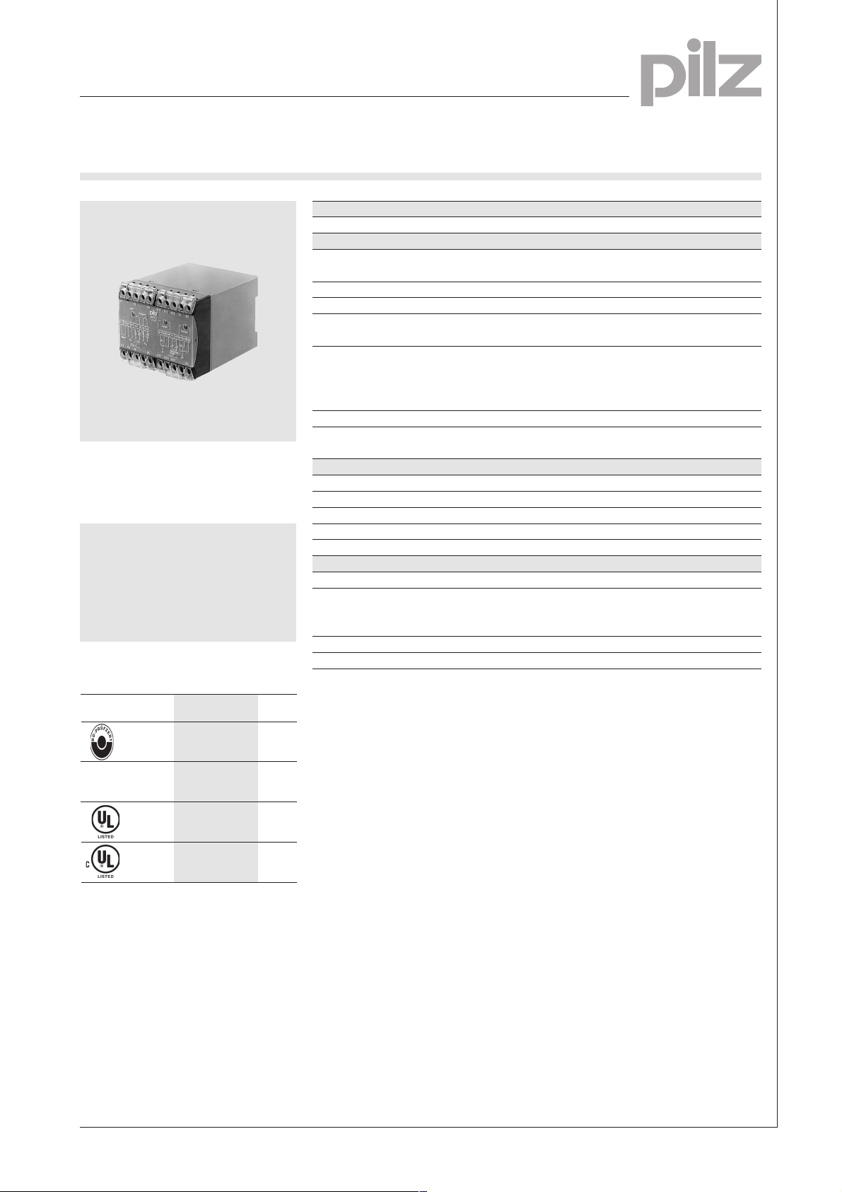
Safety Gate Monitors
Category 4, EN 954-1
PST 2
Safety gate monitor in accordance
with VDE 0113-1, 11/98, EN 602041, 12/97 and IEC 204-1, 11/98.
Features
● Simultaneity monitoring
● Connection for start-up test
button
● Automatic reset selectable
Approvals
Technical Details PST 2
Electrical Data
Supply Voltage AC: 24, 42, 110, 120, 230, 240 V
DC: 24 V
Tolerance 85 ... 110 %
Power Consumption Approx. 4 W/9 VA
Voltage and Current at the 24 VDC, 50 mA
Input Circuits 1/2
Switching Capability in accordance with
EN 60947-4-1, 02/01 AC1: 240 V/4,5 A/1100 VA
DC1: 24 V/4,5 A/110 W
EN 60947-5-1, 11/97 (DC13: 6 cycles/min.)
Output Contacts 2 safety contacts (N/O)
Contact Fuse Protection 6 A quick or 4 A slow
(EN 60947-5-1, 08/00)
Times
Delay-on Energisation Approx. 100 ms
Delay-on De-energisation Approx. 30 ms
Recovery Time Approx. 500 ms
Simultaneity channel 1/2 Approx. 4 s
Max. Supply Interruption before De-energisation 10 ms
Mechanical Data
Torque Setting on Connection Terminals 1.2 Nm (screws)
Maximum Cross Section of 2 x 2.5 mm
External Condcutors Single-core or multi-core with
Dimensions (H x W x D) 87 x 90 x 110 mm
Weight AC: 660 g, DC: 530 g
AC15: 230 V/4 A; DC13: 24 V/3A
2
crimp connectors
2
TÜV Wien
PST 2
●
●
●
●
Description
● 90 mm, P-75 housing, DIN-Rail
mounting
● Positive-guided relay outputs:
– 2 safety contacts (N/O)
● Connections for
– safety gate limit switch
– external simulation button
● LEDs for power, channel 1 and
channel 2
● Increase in the number of
safety contacts available by
connecting expander modules.
Operating Modes
● Dual-channel operation
NSG-D-2-074-06/02
Page 2
Safety Gate Monitors
14
K6 K7
13
X1 X2
K6
K7
1L1
(1L+)
1L2
(1L-)
24
23
Category 4, EN 954-1
PST 2
2
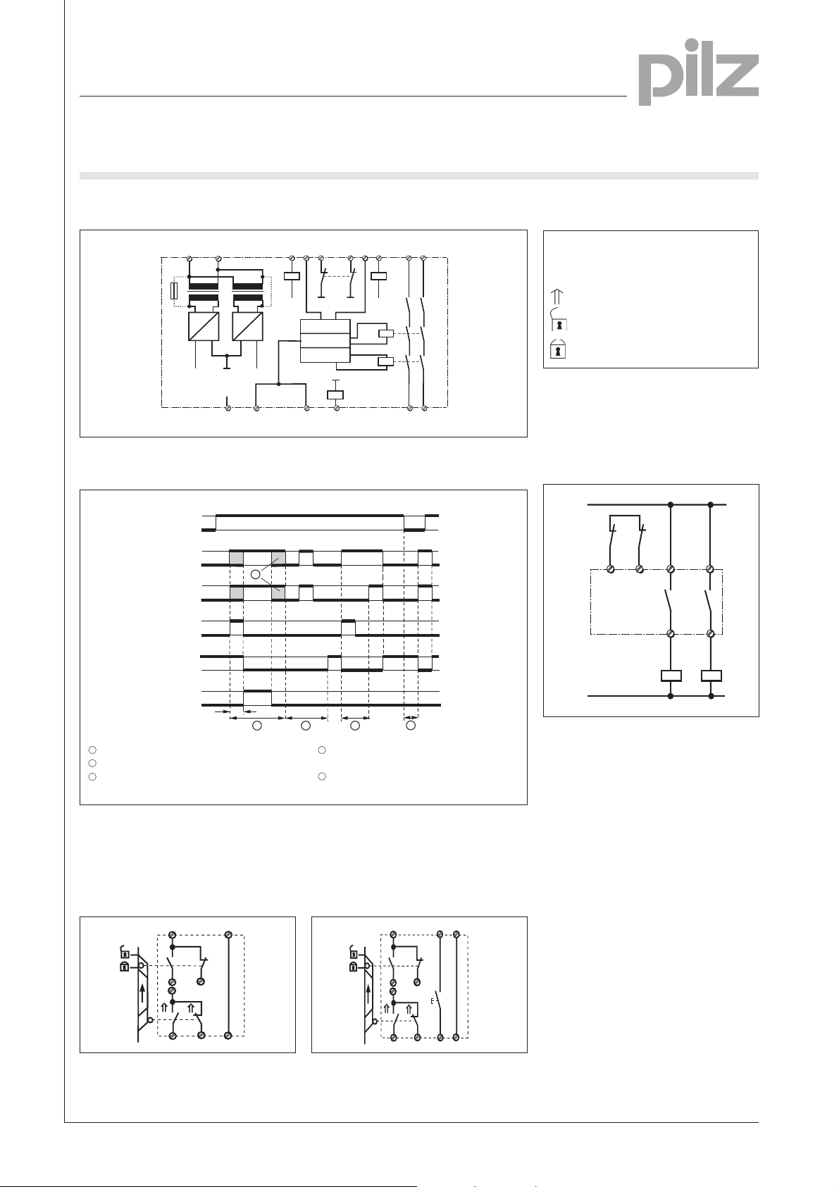
Internal Wiring Diagram
U
B
A1
(L+)
(L-)
T1
F1
~
G1
=
–
Feedback control loop
Function Diagram
1
U
B
0
Input circuit 1
Input circuit 2
Simultaneity
Feedback
control loop
Output
1
0
1
0
1
t
g
0
1
0
1
0
– Key
A2
T2
~
G2
0 V
+
X1
Input circuit
S13
K1
+
=
+
X2
Simulation circuit
S11
K3
Switch-on logic
Channel 1
Channel 2
K3
Y2
Y1
Input circuit
S21
S22
S23 13 23S12
–
K2
K5
Safety contacts
K4
K1 K4
14 24
S1/S2: E-STOP or safety gate switch
S3: Simulation button
Switch operated
Gate open
Gate closed
● Increase in contacts available
The number of output contacts can
be increased by using expander
modules or relays/contactors with
positive-guided contacts.
5
t
g
1
2
3
4
1
Normal operating cycle
1
Fault in feedback control loop
3
Fault: difference S1, S2 > t
External Wiring
● Example 1
Dual-channel safety gate control with
automatic reset.
S11
S1
S12
S21
S2
S22
S23
X1
S13
X2
4
Fault:
S1 and S2 before U
5
g
Undefined time period
B
● Example 2
Dual-channel safety gate control with
simulation for opening and closing
the safety gate.
S1
S12
S21
S2
S23
S13
Y1
X1
S3
X2
Y2
NSG-D-2-074-06/02
S11
S22
Page 3
Safety Gate Monitors
Category 4, EN 954-1
PST 2
General Technical Data
Unless stated otherwise in the technical details for the specific unit
Electrical Data
Frequency Range AC 50 ... 60 Hz
Residual Ripple DC 160 %
Contact Material AgSnO
Continuous Duty 100 %
Environmental Data
EMC EN 50081-1, 01/92, EN 61000-6-2, 03/00
Vibration in accordance with Frequency: 10 ... 55 Hz,
EN 60068-2-6, 04/95 Amplitude: 0.35 mm
Climatic Suitability DIN IEC 60068-2-3, 12/86
Airgap Creepage DIN VDE 0110-1, 04/97
Ambient Temperature -10 ... +55 °C
Storage Temperature -40 ... +85 °C
Mechanical Data
Torque Setting on Connection Terminals 0.6 Nm (screws)
Mounting Position Any
Housing Material Thermoplast Noryl SE 100
Protection Mounting: IP 54
2
Housing: IP 40
Terminal Range: IP 20
2
The units were tested in accordance with the relevant standards current at
the time of development.
Order References
Type U
PST 2 24 V DC 420 180
PST 2 24 V AC 420 100
PST 2 42 V AC 420 110
PST 2 110 V AC 420 130
PST 2 120 V AC 420 140
PST 2 230 V AC 420 150
PST 2 240 V AC 420 155
B
Order No.
NSG-D-2-074-06/02
 Loading...