

Page 1
Technical Catalogue
PSSuniversal
Planning Guide
DRAFT
Issue 01/05
Page 2

PSSuniversal
Contents Page
PSSuniversal system
Basics
System description
Modular structure 1.1-1
Module bus 1.1-2
Structure of module bus 1.1-2
Maximum system expansion 1.1-3
System limits 1.1-3
Local enable principle 1.1-4
Connection labelling on the base modules 1.1-5
Colour marking of connection levels 1.1-5
Separating supplies to form supply groups 1.1-6
Installation
Mounting position 1.2-1
Mounting rail 1.2-1
Module layout 1.2-1
Mounting distances 1.2-2
Installing the head module 1.2-3
Removing the head module 1.2-4
Installing base modules 1.2-5
Removing base modules 1.2-6
Installing an end bracket at the start of the system 1.2-7
Removing an end bracket at the start of the system 1.2-7
Installing a terminating plate and end bracket at the end of the system 1.2-8
Removing a terminating plate and end bracket at the end of the system 1.2-9
Inserting an electronic module 1.2-10
Mechanical coding 1.2-11
Removing an electronic module 1.2-12
Earthing 1.2-13
Pilz GmbH & Co. KG, Sichere Automation, Felix-Wankel-Straße 2, 73760 Ostfildern, Germany
Telephone +49 711 3409-0, Telefax +49 711 3409-133, E-Mail: [email protected]
Status 01/05
1
Page 3
PSSuniversal
Modules
Head modules
PSSu H SB 2.1-1
PSSu H SB DP 2.1-9
Supply voltage modules
PSSu E F PS 2.2-1
PSSu E F PS1 2.2-11
PSSu E F PS-P 2.2-21
PSSu E F BSW 2.2-31
Digital input/output (standard)
PSSu E S 4DI 2.3-1
PSSu E S 4DO 0.5 2.3-9
PSSu E S 2DO 2 2.3-17
Digital input/output (failsafe)
PSSu E F 4DI 2.4-1
PSSu E F 4DO 0.5 2.4-11
PSSu E F 2DO 2 2.4-21
PSSu E F 2DOR 8 2.4-31
PSSu E F 4DI OZ 2 2.4-43
Voltage distribution
PSSu E PD 2.5-1
Order reference
Module overview
Electronic modules with base modules (screw terminals) 3.1-1
Electronic modules with base modules (cage clamp terminals) 3.1-2
Pilz GmbH & Co. KG, Sichere Automation, Felix-Wankel-Straße 2, 73760 Ostfildern, Germany
2
Telephone +49 711 3409-0, Telefax +49 711 3409-133, E-Mail: [email protected]
Status 01/05
Page 4
PSSuniversal
Basics
System description
Modular structure
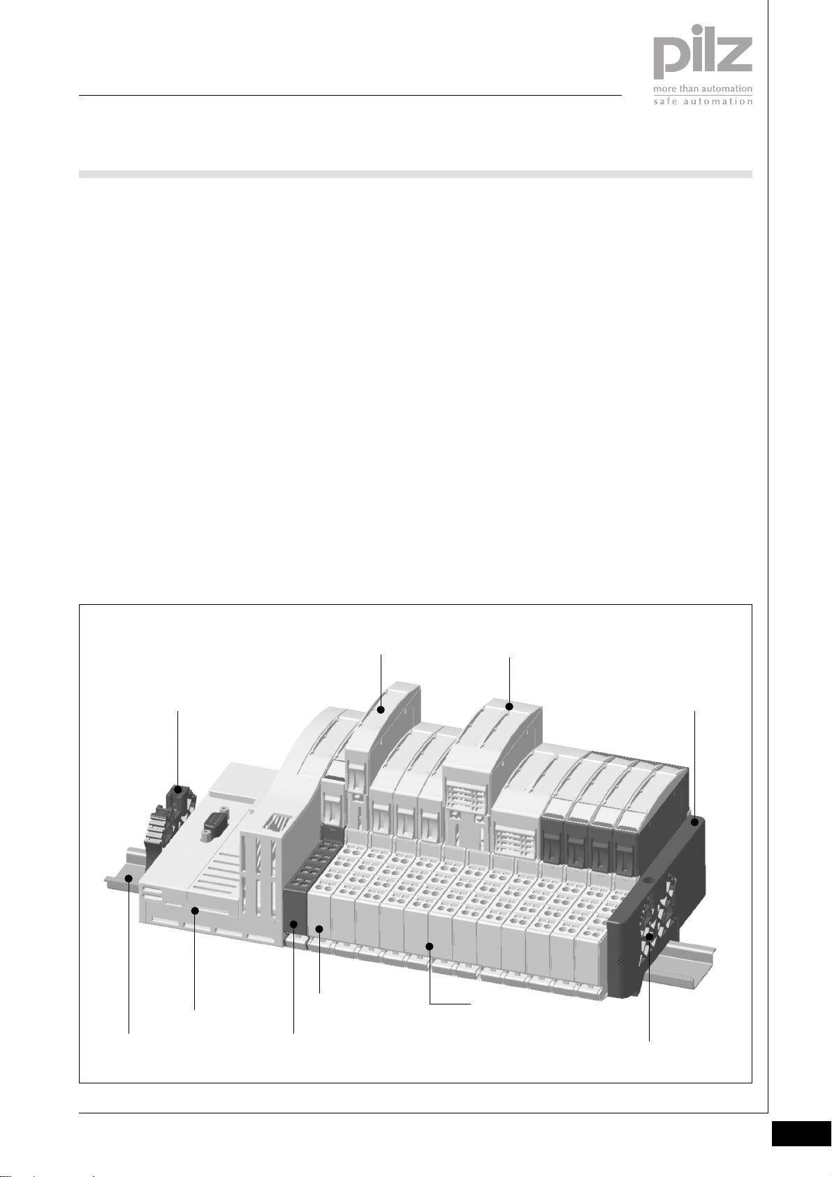
The PSS universal (PSSu) from Pilz is
a modular system for use in the
decentralised periphery of plant and
machinery. A modular PSSu type
system consists of:
` One head module
` At least one supply voltage
module
` Input/output modules for standard
and failsafe applications, which
may be installed in any sequence
` End bracket at the start of the
system to secure the system on
the mounting rail
` Terminating plate with integratable
end bracket at the end of the
system to secure the system on
the mounting rail
Head module
` Connects the sensor/actuator
level for standard applications to
master controllers via various
standard bus systems (e.g.
PROFIBUS)
` Connects the sensor/actuator
level for failsafe applications to
SafetyBUS p
` Co-ordinates the entire process
data traffic for standard and
failsafe applications
` Permits a failsafe output to be
switched via a standard signal,
depending on an enable from a
failsafe signal (local enable
principle)
Supply voltage modules
` Available for various functions
` Consist of an electronic module
and a base module
Input/output modules
` Available for a wide range of
input/output functions
` Consist of an electronic module
and a base module
Base modules
` Carrier units for the supply voltage
and input/output modules
` Used to connect the field wiring
` Available with the following
connection types:
- Cage clamp terminals or
- Screw terminals
Electronic modules
` Are plugged into base modules
` Can be inserted/removed
independently from the base
module
` Determine the function of the
supply voltage or input/output
module
` Communicate with the head
module via the module bus
2
End bracket
Head module
Electronic module
(grid width 1 x 12.6 mm)
Base module
(grid width 1 x 12.6 mm)
Electronic module
(grid width 2 x 12.6 mm)
Terminating plate
Base module
(grid width 2 x 12.6 mm)
Mounting rail
(DIN EN50022)
Pilz GmbH & Co. KG, Sichere Automation, Felix-Wankel-Straße 2, 73760 Ostfildern, Germany
Telephone +49 711 3409-0, Telefax +49 711 3409-133, E-Mail: [email protected]
Supply voltage module
(electronic module + base module)
End bracket
(integrated into terminating plate)
Status 01/05
1.1-1
Page 5
PSSuniversal
Basics
System description
Module bus
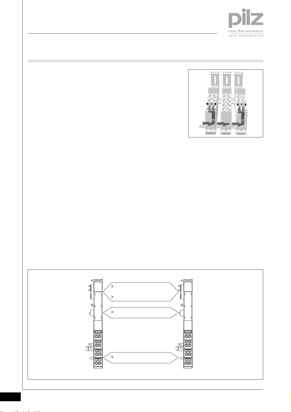
The module bus is formed by
arranging the base modules together
and connecting them via a
mechanical latch.
` Data
2 independent bus systems are
available for FS data and ST data.
The data is processed in the head
module.
` Module supply
Supply for the head module and
the electronic modules. Various
supply voltage modules are
available for different functions
(e.g. voltage refresh, separating
the supply).
` Periphery supply
The supply for the actuators (load)
or input test pulses is provided at
the base module contacts,
depending on the function of the
electronic module. Various supply
voltage modules are available for
different functions.
The connection on the module
bus can be disconnected in order
to form supply groups. In this
case it is necessary to use an
appropriate supply module, which
disconnects the supply (module
supply, periphery supply and Crail supply) to the preceding (lefthand) modules and provides a
new supply to subsequent (righthand) modules.
` C-rail
The C-rail is routed through all the
base modules via the module bus.
The C-rail is an additional power
rail, which is attached to the base
module connections. It is intended
as an option, providing additional
power if required.
Access to the C-rail is available
through the use of base modules
which contain the letter “C” in
their description (e.g. PSSu BP1/8 S). The base module
connections on which the C-rail is
available are marked with a black
bar across the whole connection
level. I/O modules normally route
the C-rail connections on
connection level 3.
If the supply is separated on base
modules containing supply
modules, this is symbolised by the
fact that only the right-hand
connection on the connection
level is marked with a black bar.
CC
C
CC
This is normally connection 24.
Permitted infeed at C-rail:
- PE or
- 0 V or
- Screen or
- - 24 VDC ... + 24 VDC,
max. 10 A
Make sure that the C-rail supply
belongs to the same circuit as the
other base module connections.
1.1-2
Structure of module bus
Module bus
Communication rail
(FS + ST data)
Rail for module supply
Rail for periphery supply
C-rail (cross connection)
Base module Base module
Pilz GmbH & Co. KG, Sichere Automation, Felix-Wankel-Straße 2, 73760 Ostfildern, Germany
Telephone +49 711 3409-0, Telefax +49 711 3409-133, E-Mail: [email protected]
Status 01/05
Page 6
PSSuniversal
Basics
System description
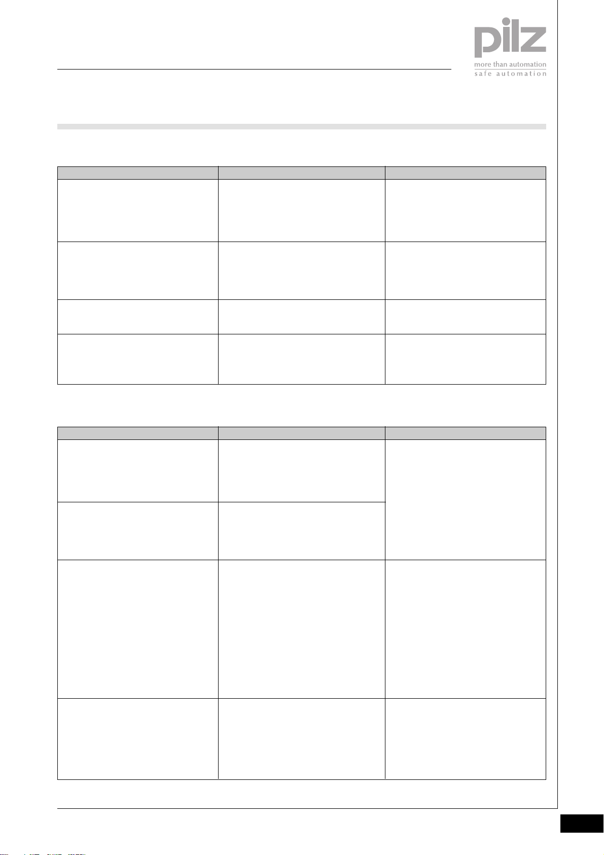
Maximum system expansion
Module type
Input/output modules in total
(identifier: PSSu E F ... / PSSu E S ...)
Input/output modules for
ST applications
(identifier: PSSu E S ...)
Input/output modules for
FS applications
(identifier: PSSu E F ...)
Output modules with
dual-pole outputs for
FS applications
(identifier: PSSu E F ... OZ...)
System limits
Module supply
when supplied via
- PSSu E F PS
Module supply
when supplied via
- PSSu E F PS1
Number of modules per system
Max. 64
Max. 64
Max. 32
Max. 16
Max. current load ExplanationSystem supply
Max. 1.5 A
Max. 2 A
Explanation
Details are valid for designing a PSSu
system with any combination of ST
modules and FS modules, provided all
the following conditions are met.
Details are valid for designing a PSSu
system with ST modules only.
Restrictions may apply, depending on
the standard bus system that is used.
Details are valid for designing a PSSu
system with FS modules only.
Details are valid for designing a PSSu
system with dual-pole FS output
modules only
(e.g. PSSu E F DI OZ 2).
The load is determined by the current
consumption of the head module and
electronic modules that are used. If a
heavier load arises, an additional supply
module must be used to refresh the
module supply. Further details can be
found in the description of the relevant
supply module.
2
Periphery supply
when supplied via
- PSSu E F PS
- PSSu E F PS1
- PSSu E F PS-P
C-rail
Pilz GmbH & Co. KG, Sichere Automation, Felix-Wankel-Straße 2, 73760 Ostfildern, Germany
Telephone +49 711 3409-0, Telefax +49 711 3409-133, E-Mail: [email protected]
Max. 10 A
Max. 10 A
The module bus rail for periphery supply
can take a max. 10 A load. If a heavier
load arises, an additional supply module
must be used to refresh the periphery
supply. The load is determined by the
current consumption of the sensors/
actuators on the electronic modules that
are used. Further details can be found in
the description of the relevant supply
module.
The C-rail can take a max. 10 A load. If a
heavier load arises, an additional supply
module must be used. Further details
can be found in the description of the
relevant supply module.
Status 01/05
1.1-3
Page 7
PSSuniversal
Basics
System description
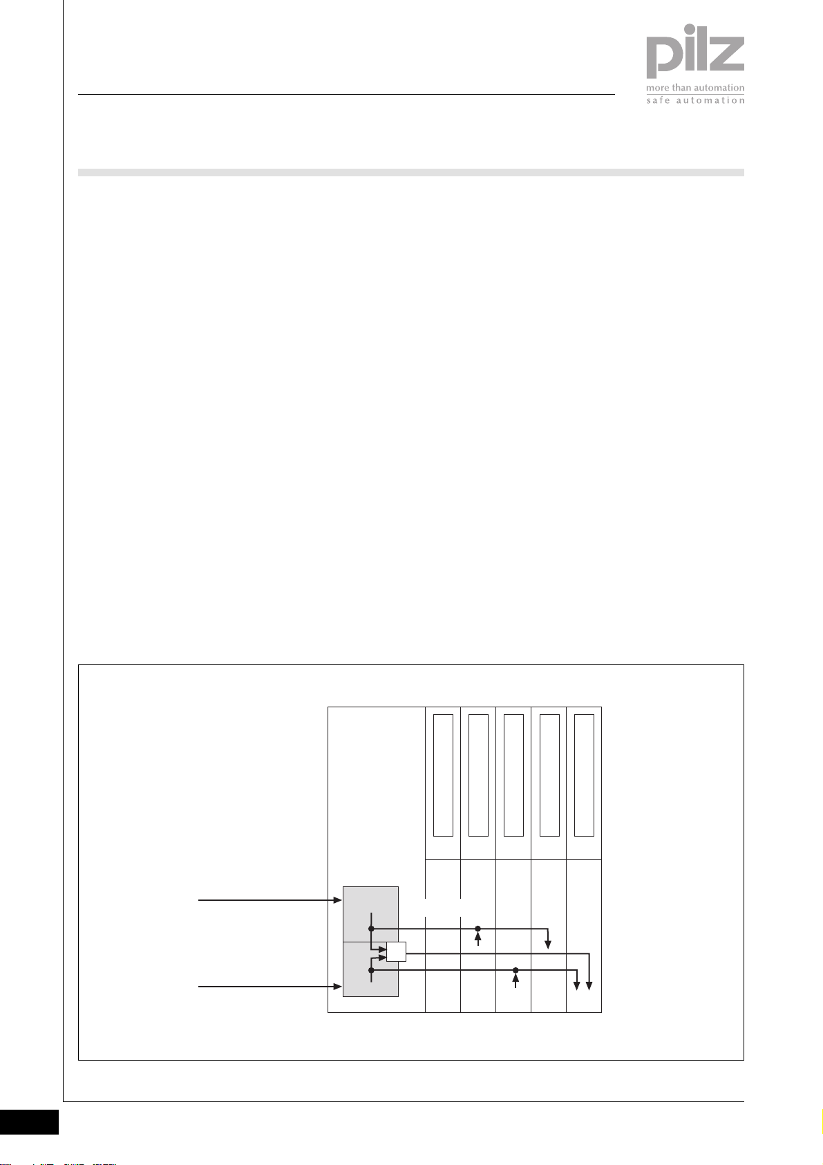
Local enable principle
The new local enable principle
technique means that outputs on
failsafe output modules can now be
switched via a standard bus system
(e.g. PROFIBUS).
Configuration of the local enable
principle
` Via the PSS WIN-PRO system
software
` By configuring FS output modules
for the relevant standard bus
system (e.g. in the case of
Profibus, included in the GSD file)
` By assigning an FS output to a bit
in the ST process image of
outputs (ST-PIO). The FS output
will therefore operate as an enable
output.
` Ability to read the FS inputs via
the standard bus system.
Operation of the local enable
principle
` The configured FS outputs are
driven via a standard bus system.
` Provided the enable output carries
a “1” signal, the configured FS
outputs can be driven via a
standard bus system.
As soon as the enable output
carries a “0” signal, the configured
FS outputs are shut down safely.
Control via the standard bus
system is ignored.
Function model of the local enable
principle
Control via
standard bus system
Control via
SafetyBUS p
ST Data
FS Data
Head Module
Module Bus
&
Power Supply
Input Module (ST)
Output Module (ST)
Input Module (FS)
Output Module (FS)
1.1-4
Pilz GmbH & Co. KG, Sichere Automation, Felix-Wankel-Straße 2, 73760 Ostfildern, Germany
Telephone +49 711 3409-0, Telefax +49 711 3409-133, E-Mail: [email protected]
Status 01/05
Page 8

PSSuniversal
Basics
System description
Connection labelling on the base
modules
The connections on the base
modules are indicated via two-digit
numbers. The first digit denotes the
column on the module. The second
digit denotes the connection level
within the PSSu system.
Example:
Colour marking of connection levels
Colour marking of connection levels
The colour marking on the different
connection levels is helpful when it
comes to wiring. Various colour
markers are available to label the
connection levels. For the connection
diagram to remain consistent it
makes sense to arrange I/O modules
of the same type into groups (see
example).
The connection levels are typically
assigned as follows:
` Connection level 1 and 4
On I/O modules, connection levels
1 and 4 typically contain the
module’s inputs or outputs.
Marking in the example:
- Black [3]
` Connection levels 2 and 3
On I/O modules, connection levels
2 and 3 typically contain the
common supplies (+24 VDC, test
pulse outputs, 0 VDC).
Marking in the example:
- Red [1]: +24 VDC/test pulses
- Blue [2]: 0 VDC
2
Head Module
PSSu E F 4DI
Power Supply
2111
2111
2212
2212
2313
2313
2414
2414
Input Modules Output Modules
PSSu E F 2DO 2
PSSu E S 4DI
PSSu E F 4DI
2111
2212
[1] [2]
2313
2414
2111
2212
2313
2414
PSSu E S 4DI
2111
2212
2313
2414
PSSu E F 2DO 2
PSSu E F 4DI
2111
2111
[3]
2212
2212
2313
2313
2414
2414
[3]
PSSu E S 2DO 2
2111
2111
2212
2212
2313
2313
[2][1]
2414
2414
PSSu E F 4DO 0.5
PSSu E S 4DO 0.5
Connection Level 1
2111
2111
Connection Level 2
2212
2212
Connection Level 3
2313
2313
Connection Level 4
2414
2414
[1] : + 24 VDC
[2] : 0 VDC
[3] : Inputs/outputs
Pilz GmbH & Co. KG, Sichere Automation, Felix-Wankel-Straße 2, 73760 Ostfildern, Germany
Telephone +49 711 3409-0, Telefax +49 711 3409-133, E-Mail: [email protected]
Status 01/05
1.1-5
Page 9
PSSuniversal
Basics
System description
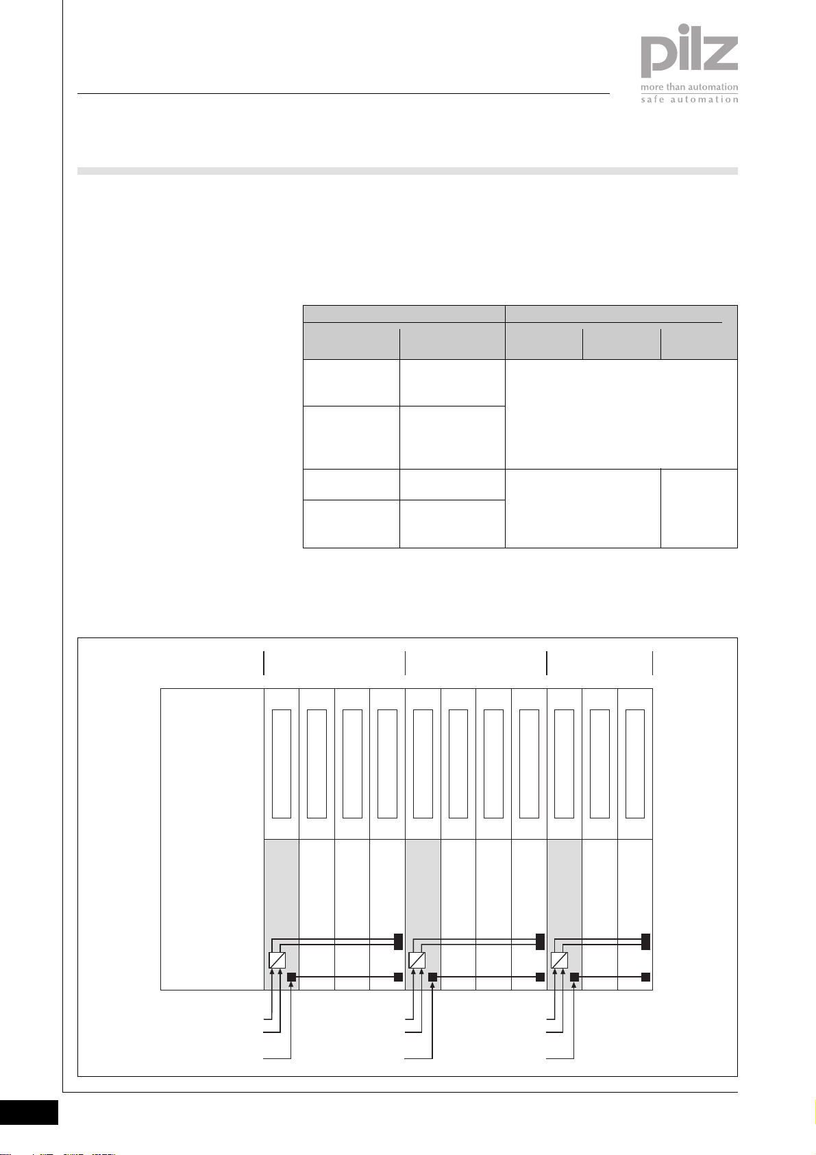
Separating supplies to form supply
groups
Supply groups are formed by
separating the 24 V supply (periphery
supply) and, if necessary, also the
5 V supply (module supply). In this
case it is necessary to use a supply
module that disconnects the supply
(periphery supply, C-rail supply and,
if necessary, the module supply) to
the preceding (left-hand) modules
and provides a new supply to
subsequent (right-hand) modules.
Provided an appropriate base
module is used, in principle any
electronic supply voltage module is
suitable for separating supplies.
Principle:
Formation of supply groups for
periphery supply
In each case you should take note of
the description of the relevant
electronic supply voltage module.
For example, supplies can be
separated on the following modules:
Modules
Electronic module
PSSu E F PS
(no module
buffer)
PSSu E F PS1
(module buffer
for max.
20 modules)
PSSu E F PS-P
PSSu E F BSW
(block switching)
Base module
PSSu BS-R 1/8 S
PSSu BS-R 1/8 C
PSSu BS-R 2/8 S
PSSu BS-R 2/8 C
PSSu BS 1/8 S
PSSu BS 1/8 C
PSSu BS 2/8 S
PSSu BS 2/8 C
Separation of supply
C-rail Periphery
supply
Separation of supply from left-hand
modules and
supply infeed to right-hand modules
Separation of supply from
left-hand modules and
supply infeed to right-hand
modules
Module
supply
No separation
of supply
(5 V potential
looped
through)
Head Module
Periphery Supply 1
(24 V DC)
C-rail
Supply
Supply Group 1 Supply Group 2 Supply Group 3
I/O Module
I/O Module
Power Supply
Power Supply
24 V DC 24 V DC 24 V DC
Periphery Supply 2
(24 V DC)
C-rail
Supply
I/O Module
I/O Module
Power Supply
Periphery Supply 3
(24 V DC)
C-rail
Supply
I/O Module
I/O Module
I/O Module
Power Supply
I/O Module
1.1-6
Pilz GmbH & Co. KG, Sichere Automation, Felix-Wankel-Straße 2, 73760 Ostfildern, Germany
Telephone +49 711 3409-0, Telefax +49 711 3409-133, E-Mail: [email protected]
Status 01/05
Page 10
PSSuniversal
Basics
Installation
Mounting position
` A PSSu system should preferably
be installed horizontally on a
vertical wall.
` If other mounting positions are
used (e.g. vertical installation),
there will be certain restrictions
with regard to
- Ambient temperature
Optimum upward heat
dissipation can no longer be
guaranteed.
- Vibration and shock stress
There will be increased
requirements on the system
fastenings: use additional
metallic end brackets!
Mounting rail
` A PSSu system is designed to be
installed on a zinc plated DIN rail
in accordance with DIN EN 50022.
Dimensions:
35 x 7.5 mm or 35 x 15 mm
` Where vibration and shock stress
place increased requirements on
the system fastenings, it is
recommended that the mounting
rail is screwed to the mounting
plate approximately every
200 mm.
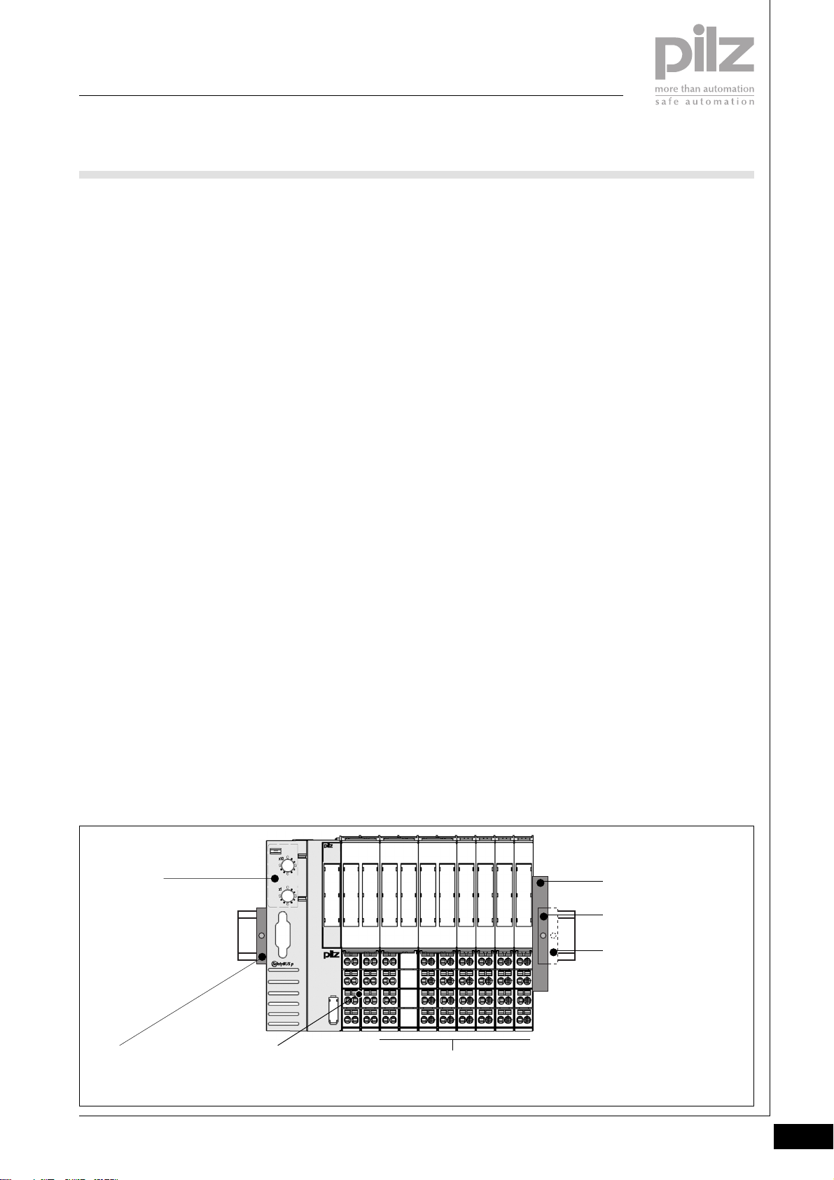
Module layout
` The first module on a PSSu
system is always a head module.
` A supply voltage module is always
connected to the right of the head
module
- To supply the module electronics to the head module and
subsequent I/O modules
- To provide 24 VDC for the
periphery supply
` Next right it is possible to install
I/O modules for FS and ST
applications.
- The I/O modules (input
modules, output modules) can
be installed in any order.
- I/O modules for FS applications
and ST applications can be
combined as required.
- In various applications it makes
sense to combine specific
modules into groups.
- It is not possible to mix base
modules with screw terminals
and cage clamp terminals.
- The max. number of I/O
modules is determined through
the defined system limits.
` Supply voltage modules may be
required to refresh the supply to
the module electronics. This can
be determined through the
defined system limits.
` To form supply groups, an
additional voltage supply module
is required at the start of each
group. The modules belonging to
the supply group will then follow
to the right.
` The final element in a PSSu
system is always a terminating
plate, containing the bus
terminating resistors.
` Various fastening elements are
used at the start and end of the
system to secure the system on
the mounting rail:
- End bracket at the start of the
system
- Plastic version (standard)
- Metal version
(increased requirements with
regard to vibration and
shock stress)
- End bracket at the end of the
system
- Plastic version (standard)
- Metal version
(increased requirements with
regard to vibration and
shock stress)
2
Head
module
End bracket
(metal version
if necessary)
Pilz GmbH & Co. KG, Sichere Automation, Felix-Wankel-Straße 2, 73760 Ostfildern, Germany
Telephone +49 711 3409-0, Telefax +49 711 3409-133, E-Mail: [email protected]
Supply voltage module
I/O modules
with supply voltage modules to separate the supplies
if necessary)
Terminating plate
with integrated
End bracket
Additional metal end
bracket if required
Status 01/05
1.2-1
Page 11
PSSuniversal
Basics
Installation
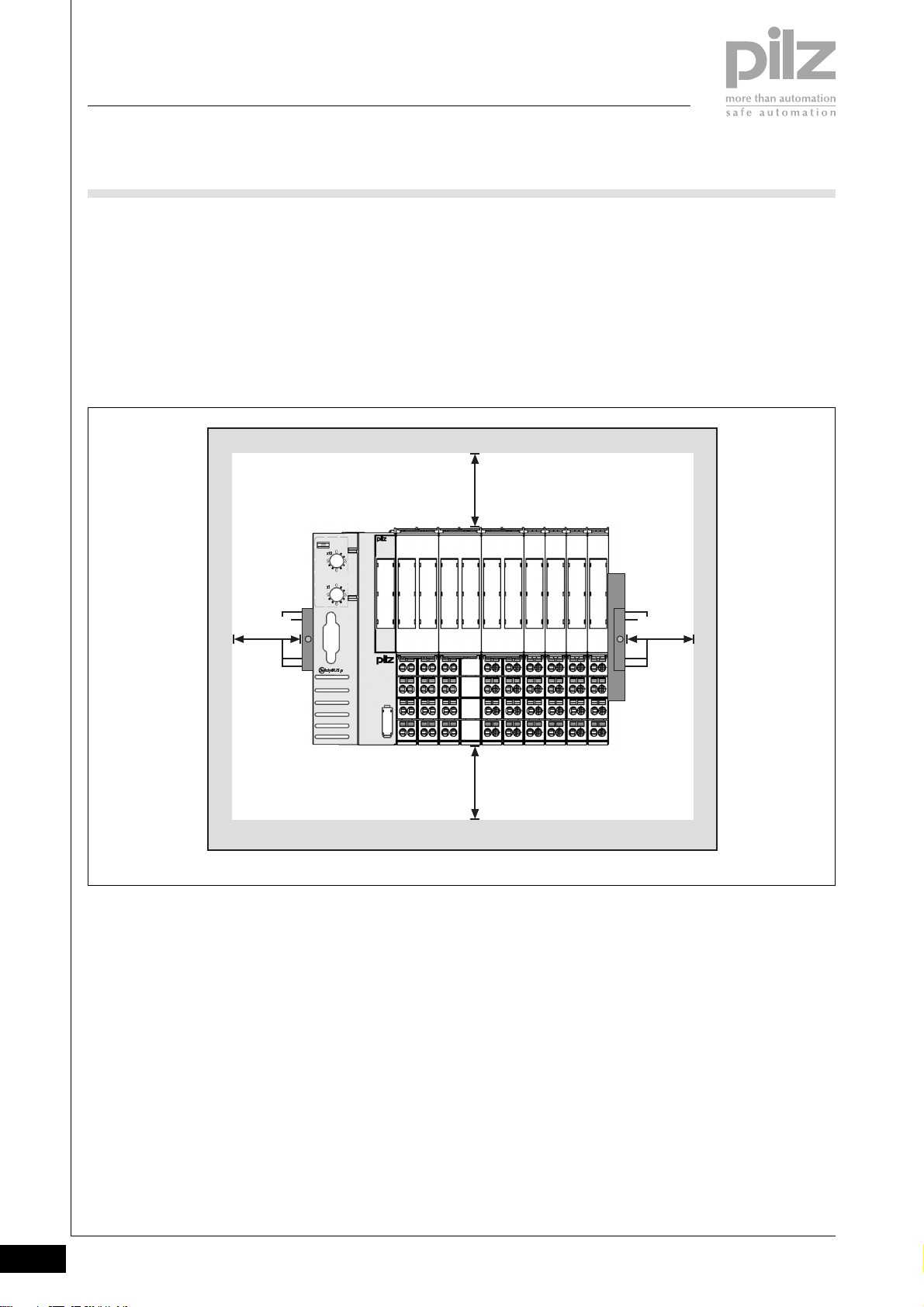
Mounting distances
The values stated in the diagram
below are minimum specifications.
20 mm 20 mm
Appropriate air conditioning may also
be required. The values stated for
ambient temperature must be
maintained. These values can be
found in the technical details for the
individual modules.
35 mm
35 mm
1.2-2
Pilz GmbH & Co. KG, Sichere Automation, Felix-Wankel-Straße 2, 73760 Ostfildern, Germany
Telephone +49 711 3409-0, Telefax +49 711 3409-133, E-Mail: [email protected]
Status 01/05
Page 12
PSSuniversal
Basics
Installation
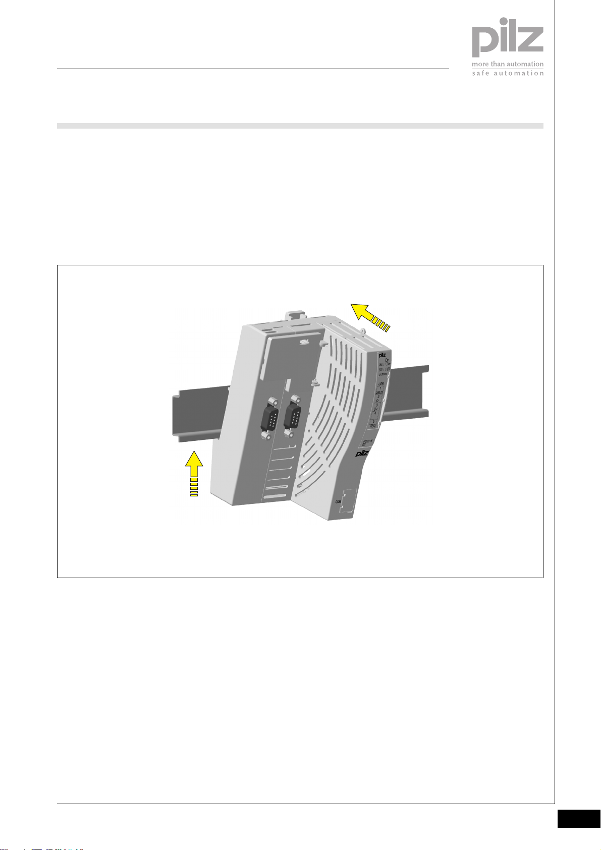
Installing the head module
` Prerequisites:
- The mounting rail must already
be installed.
` Install an appropriate end bracket
to the left of the head module or
leave enough space to install it
later.
` Procedure:
- Slot the groove on the head
module on to the mounting rail
from below [1].
- Push the head module back [2]
until you hear it lock into
position.
2
[2]
[1]
Pilz GmbH & Co. KG, Sichere Automation, Felix-Wankel-Straße 2, 73760 Ostfildern, Germany
Telephone +49 711 3409-0, Telefax +49 711 3409-133, E-Mail: [email protected]
Status 01/05
1.2-3
Page 13
PSSuniversal
Basics
Installation
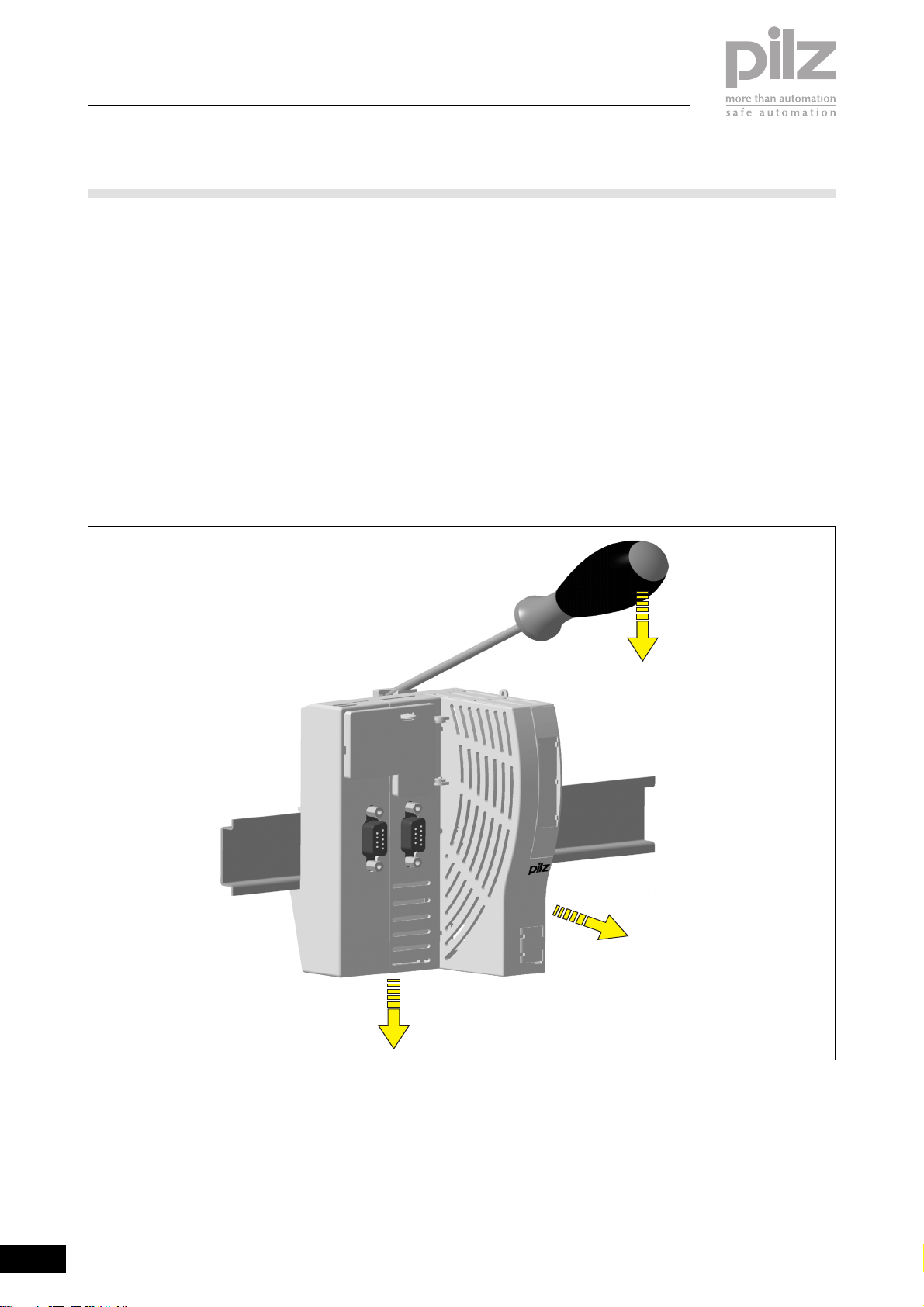
Removing the head module
` Prerequisite:
- The supply voltage must be
switched off
- The bus connections must be
disconnected
- All the wiring must be removed
- All the base modules must have
been moved to the right (min.
30 mm) or have already been
removed.
` Procedure:
- Using a screwdriver, push the
rear locking element [1]
upwards until the locking hook
releases the anchor.
- Pivot the head module and
screw driver forwards [2] and
remove in a downward
direction [3].
[1]
[2]
[3]
1.2-4
Pilz GmbH & Co. KG, Sichere Automation, Felix-Wankel-Straße 2, 73760 Ostfildern, Germany
Telephone +49 711 3409-0, Telefax +49 711 3409-133, E-Mail: [email protected]
Status 01/05
Page 14
PSSuniversal
Basics
Installation
Installing base modules
` Prerequisite: The head module
must already be installed.
` The head module must always be
followed on the right by a base
module that is suitable for an
appropriate supply voltage
module.
` The wiring should preferably be
carried out after the base modules
are installed, but before the
electronic modules are installed.
` Please note:
- For mechanical reasons it is not
possible to mix base modules
with screw terminals and base
modules with cage clamp
terminals.
- All contacts should be
protected from contamination.
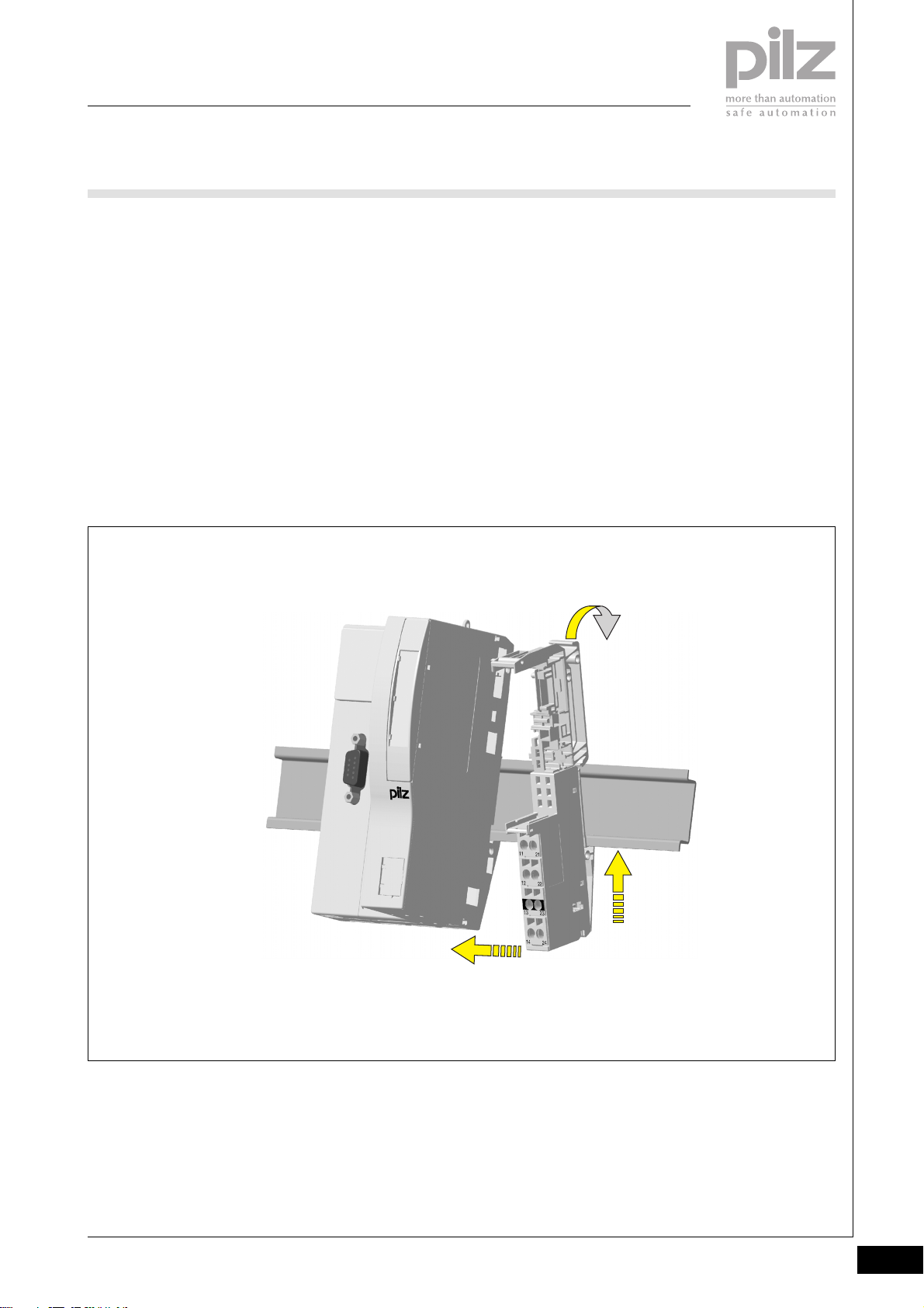
` Procedure:
The same procedure applies for all
base modules (e.g. base modules
in grid widths 1 x 12.6 mm, 2 x
12.6 mm).
- Base modules should always
be installed to the right of the
head module.
- Slot the groove on the base
module on to the mounting rail
from below [1].
- Push the base module back [2]
until you hear it lock into
position.
- On the mounting rail, slide the
base module to the left until
you hear the two lateral
mounting hooks on the
adjacent module (head module
or base module) lock into
position [3].
2
[2]
[3]
Pilz GmbH & Co. KG, Sichere Automation, Felix-Wankel-Straße 2, 73760 Ostfildern, Germany
Telephone +49 711 3409-0, Telefax +49 711 3409-133, E-Mail: [email protected]
[1]
Status 01/05
1.2-5
Page 15
PSSuniversal
Basics
Installation
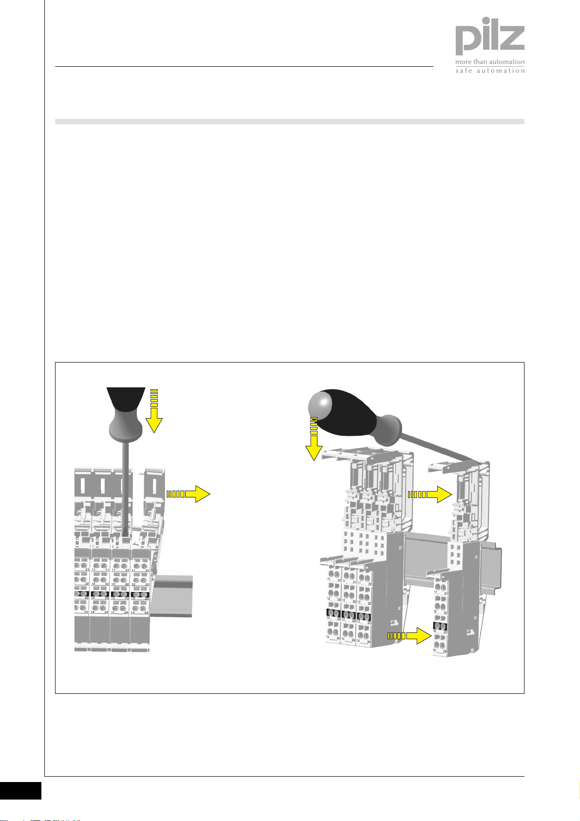
Removing base modules
` Prerequisite:
- The supply voltage on the
corresponding supply module
must be switched off
- All the wiring must be removed
- The electronic module on the
relevant base module must
have been removed, plus the
electronic module on the base
module to the left.
- All the base modules to the
right of the relevant base
module must have been moved
to the right (min. 30 mm) or
have already been removed.
[1]
` Procedure:
The same procedure applies for all
base modules (e.g. base modules
in grid widths 1 x 12.6 mm,
2 x 12.6 mm).
- Insert the screwdriver into the
square opening on the base
module to the left of the
relevant module [1].
- Push the screwdriver
downwards and keep it
pressed down.
- Use the other hand to pull the
base module to the right [2]
until the locking element on the
base module you are removing
is completely free.
- On the mounting rail, slide the
base module to the right [3]
- Using a screwdriver, push the
rear locking element [4]
upwards [5] until the locking
hook releases the anchor.
- Pivot the base module and
screw driver forwards and
remove in a downward
direction.
NOTICE
Modules may be inserted and
removed a maximum of 20 times.
After this point a correct contact can
no longer be guaranteed.
[2]
[5]
[4]
[3]
[3]
1.2-6
Pilz GmbH & Co. KG, Sichere Automation, Felix-Wankel-Straße 2, 73760 Ostfildern, Germany
Telephone +49 711 3409-0, Telefax +49 711 3409-133, E-Mail: [email protected]
Status 01/05
Page 16
PSSuniversal
Basics
Installation
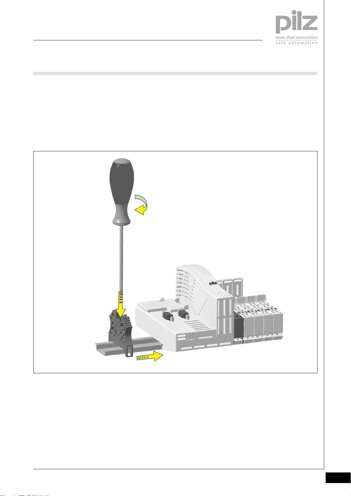
Installing an end bracket at the start
of the system
` Select an end bracket, depending
on the vibration and shock stress
(plastic version/metal version)
` Procedure:
- Use a screwdriver for slottedhead screws (M2).
- Loosen the fixing screw on the
end bracket until the terminals
are far enough apart for the end
bracket to be positioned on the
mounting rail.
[3]
- Place the end bracket on the
mounting rail, to the left of the
head module [1].
- Slide the end bracket up close
to the head module [2]
- Tighten up the end bracket [3].
2
[1]
[2]
Removing an end bracket at the start
of the system
` Procedure:
- Use a screwdriver for slottedhead screws (M2).
- Loosen the fixing screw on the
end bracket until the terminals’
clamping force is lifted.
- Remove the end bracket from
the mounting rail.
Pilz GmbH & Co. KG, Sichere Automation, Felix-Wankel-Straße 2, 73760 Ostfildern, Germany
Telephone +49 711 3409-0, Telefax +49 711 3409-133, E-Mail: [email protected]
Status 01/05
1.2-7
Page 17
PSSuniversal
Basics
Installation
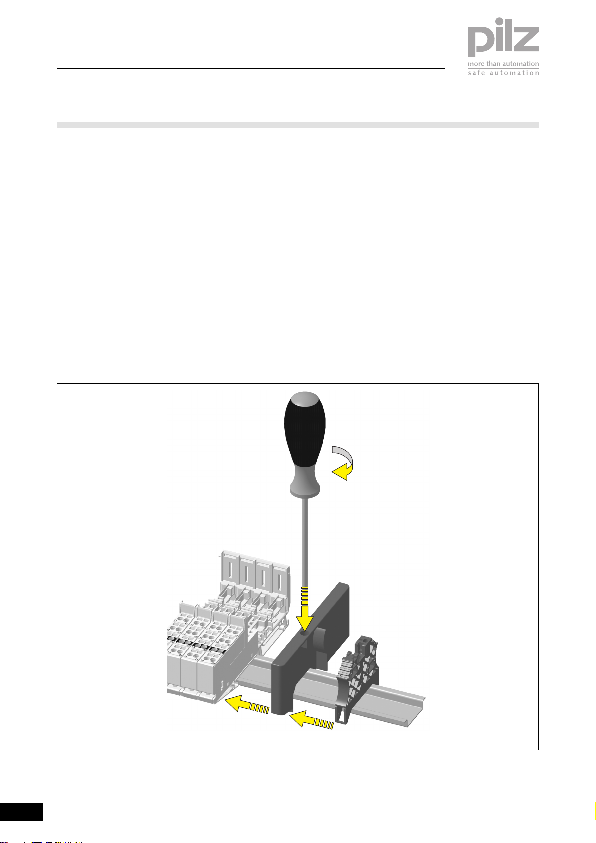
Installing a terminating plate and end
bracket at the end of the system
` Select an end bracket, depending
on the vibration and shock stress
- Plastic version of end bracket
(integrated into terminating
plate)
- Additional end bracket if
required (metal version)
` Procedure:
- Use a screwdriver for slottedhead screws (M2).
- Attach the terminating plate to
the mounting rail as the final
element on the system [1].
- Loosen the fixing screw on the
end bracket until the terminals
are far enough apart for the end
bracket to be positioned on the
mounting rail.
- Place the end bracket on the
mounting rail, to the right of the
terminating plate [2].
- Slide the end bracket and
terminating plate into each
other [3]
- Slide the terminating plate with
integrated end bracket up to
the final base module as far as
it will go [4]; ensure that contact
is made with the integrated bus
terminating resistors.
- Insert the screwdriver into the
terminating plate [5]
- Tighten up the integrated end
bracket [6].
` If an additional end bracket (metal
version) is required to secure the
system, this additional end
bracket is installed to the right of
the terminating plate.
Procedure:
- Loosen the fixing screw on the
metallic end bracket
- Place the metallic end bracket
on the mounting rail
- Slide the metallic end bracket
up close to the terminating
plate with the integrated end
bracket
- Tighten up the metallic end
bracket
[4]
[6]
[1]
[5]
[2]
[3]
1.2-8
Pilz GmbH & Co. KG, Sichere Automation, Felix-Wankel-Straße 2, 73760 Ostfildern, Germany
Telephone +49 711 3409-0, Telefax +49 711 3409-133, E-Mail: [email protected]
Status 01/05
Page 18
PSSuniversal
Basics
Installation
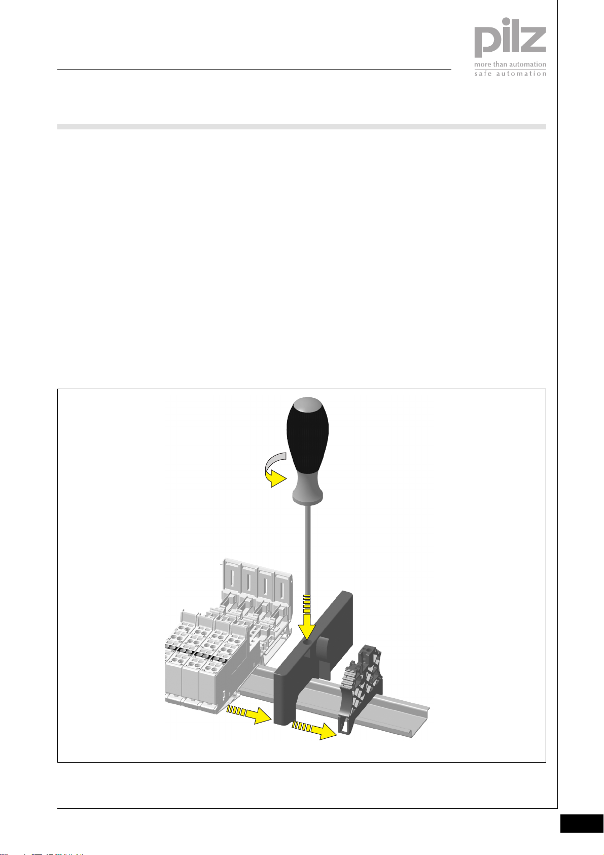
Removing a terminating plate and
end bracket at the end of the system
` Procedure:
- Use a screwdriver for slottedhead screws (M2).
- Insert the screwdriver into the
terminating plate [1]
- Loosen the fixing screw on the
end bracket [2].
- Move the terminating plate and
integrated end bracket to the
right [3].
Note: Do not damage the
elements used to connect to
the adjacent base module.
- Loosen the fixing screw on the
end bracket until the terminals’
clamping force is lifted.
- Remove the terminating plate
and integrated end bracket
from the mounting rail.
2
[3]
[2]
[1]
[3]
Pilz GmbH & Co. KG, Sichere Automation, Felix-Wankel-Straße 2, 73760 Ostfildern, Germany
Telephone +49 711 3409-0, Telefax +49 711 3409-133, E-Mail: [email protected]
Status 01/05
1.2-9
Page 19
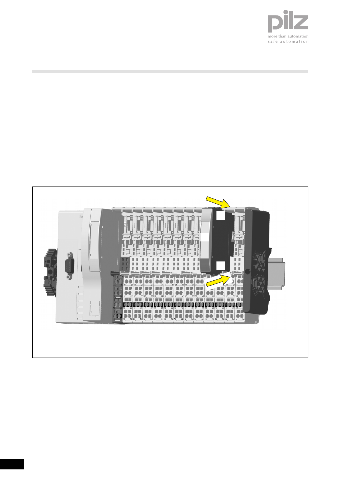
PSSuniversal
Basics
Installation
Inserting an electronic module
NOTICE
Modules may be inserted and
removed a maximum of 20 times.
After this point a correct contact can
no longer be guaranteed.
` Electronic modules should only be
plugged into base modules that
are installed and, preferably,
wired.
` Electronic modules with outputs
(output modules) may only be
inserted or removed when the
load is switched off.
If modules are inserted/removed
under load, the possibility of the
PSSu system switching to a safe
condition (STOP condition) cannot
be excluded. The corresponding
I/O-Group (SafetyBUS p) may also
switch to a STOP condition.
[2]
` Procedure:
- The electronic module must
audibly lock into position [1].
- Identify the electronic module
using the labelling strips [2]
[1]
[1]
1.2-10
Pilz GmbH & Co. KG, Sichere Automation, Felix-Wankel-Straße 2, 73760 Ostfildern, Germany
Telephone +49 711 3409-0, Telefax +49 711 3409-133, E-Mail: [email protected]
Status 01/05
Page 20
PSSuniversal
Basics
Installation
Mechanical coding
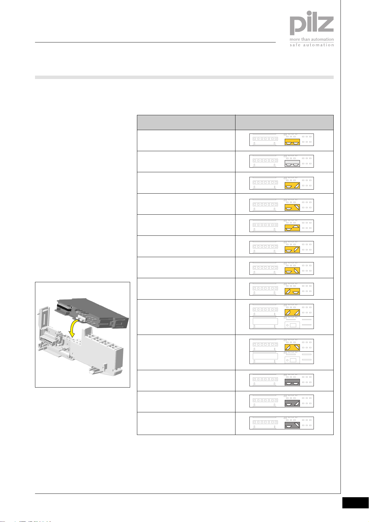
Electronic modules have a two-part
coding element. The first time an
electronic module is plugged into a
base module, one part of the coding
element remains on the electronic
module, while its counterpart is fixed
on to the base module.
The coding element is designed to
help prevent plugging errors (e.g.
when exchanging modules).
` Once a base module has been
coded, only electronic modules
with the same coding can be
inserted.
` If a new electronic module is to be
plugged into a base module that
has already been coded, you will
initially need to remove the coding
counterpart on the electronic
module.
Overview of the mechanical coding
elements on electronic modules
Electronic module
PSSu E F PS-P
Coding: yellow, A
PSSu E PD
Coding: light grey, A
PSSu E F PS
Coding: yellow, B
PSSu E F PS1
Coding: yellow, C
PSSu E F 4DI
Coding: yellow, D
PSSu E F 4DO 0.5
Coding: yellow, E
PSSu E F 2DO 2
Coding: yellow, F
Mechanical coding element
(rear view of electronic module)
2
PSSu E F DI OZ 2
Coding: yellow, G
PSSu E F 2DOR 8
Coding: yellow, H
PSSu E F BSW
Coding: yellow, I
PSSu E S 4DI
Coding: dark grey, A
PSSu E S 4DO 0.5
Coding: dark grey, B
PSSu E S 2DO 2
Coding: dark grey, C
Pilz GmbH & Co. KG, Sichere Automation, Felix-Wankel-Straße 2, 73760 Ostfildern, Germany
Telephone +49 711 3409-0, Telefax +49 711 3409-133, E-Mail: [email protected]
Status 01/05
1.2-11
Page 21
PSSuniversal
Basics
Installation
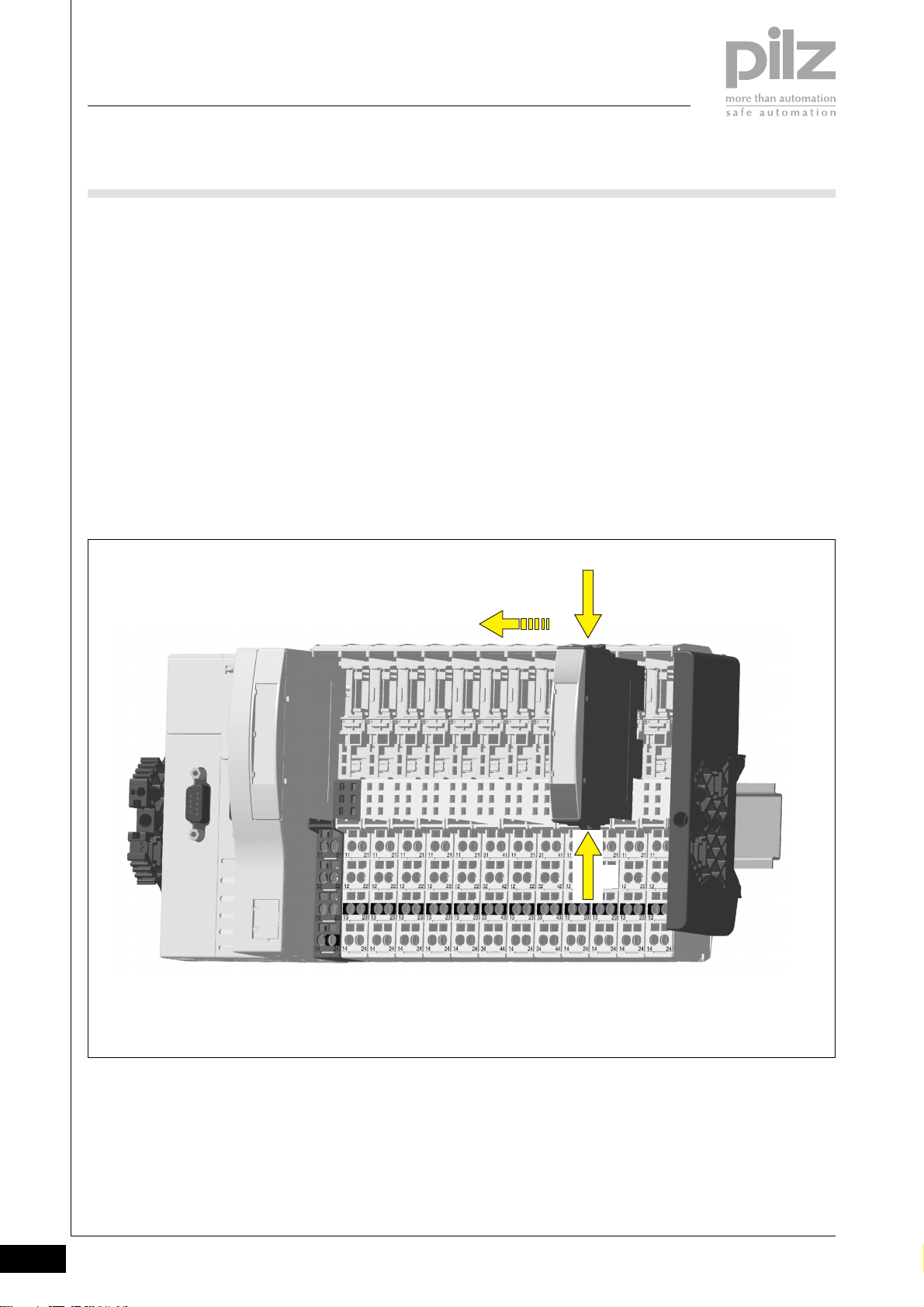
Removing an electronic module
NOTICE
Ensure that a correct contact is
made. A correct contact can no
longer be guaranteed when modules
have been inserted and removed
more than 20 times.
` Electronic modules with outputs
(output modules) may only be
inserted or removed when the
load is switched off.
If modules are inserted/removed
under load, the possibility of the
PSSu system switching to a safe
condition (STOP condition) cannot
be excluded. The corresponding
I/O-Group (SafetyBUS p) may also
switch to a STOP condition.
[2]
Procedure:
` Press the locking mechanisms [1]
together and at the same time
` Pull out the electronic module [2]
[1]
1.2-12
[1]
Pilz GmbH & Co. KG, Sichere Automation, Felix-Wankel-Straße 2, 73760 Ostfildern, Germany
Telephone +49 711 3409-0, Telefax +49 711 3409-133, E-Mail: [email protected]
Status 01/05
Page 22
PSSuniversal
Basics
Installation
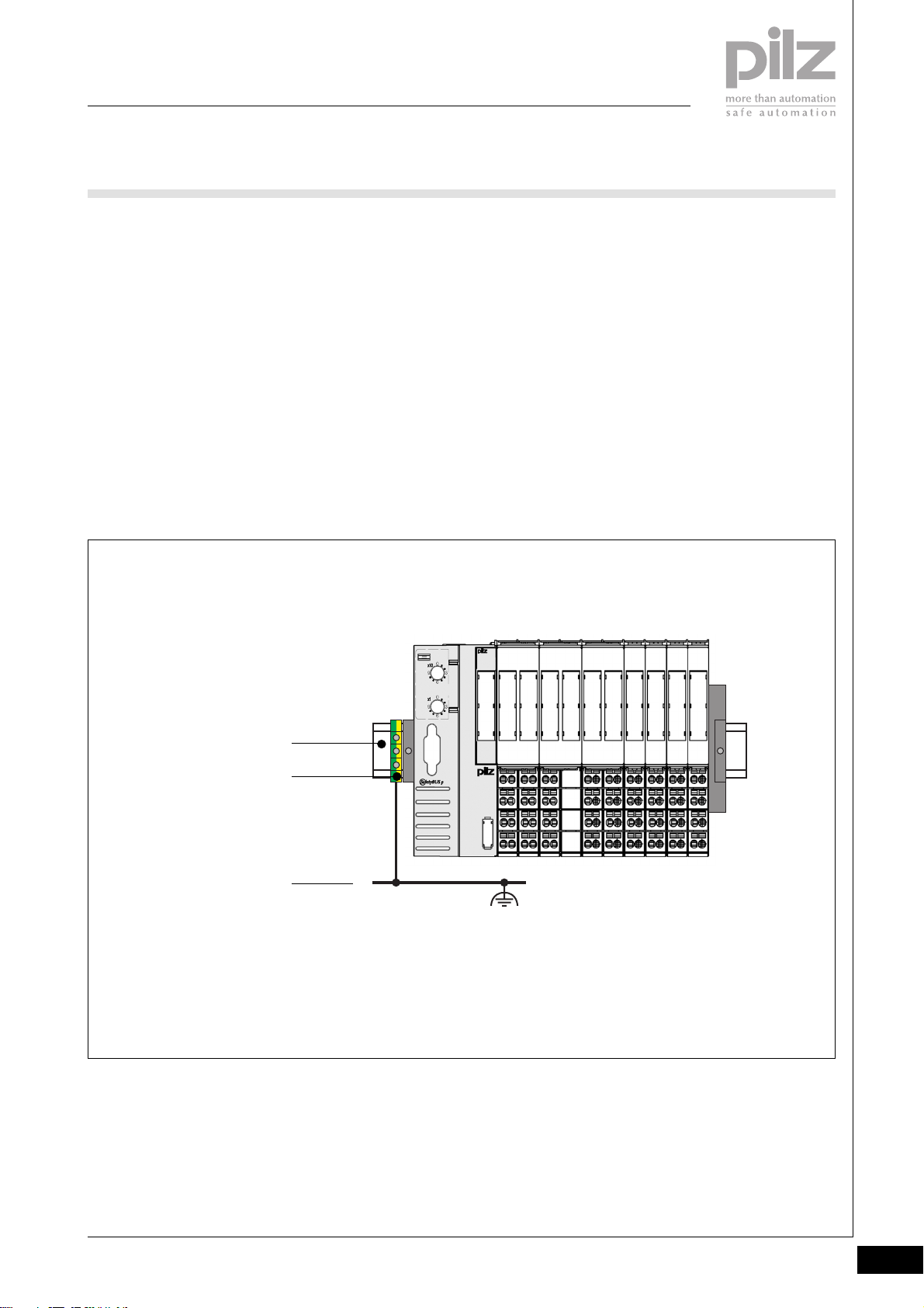
Earthing
When modules are attached to the
mounting rail, contact with the
mounting rail is made via a contact
spring. The mounting rail should be
earthed appropriately.
A special earthing terminal that can
be attached to the mounting rail is
available as an accessory.
2
Mounting rail
Earthing terminal
Functional earth
Pilz GmbH & Co. KG, Sichere Automation, Felix-Wankel-Straße 2, 73760 Ostfildern, Germany
Telephone +49 711 3409-0, Telefax +49 711 3409-133, E-Mail: [email protected]
Status 01/05
1.2-13
Page 23

PSSuniversal
Basics
Installation
Notes
1.2-14
Pilz GmbH & Co. KG, Sichere Automation, Felix-Wankel-Straße 2, 73760 Ostfildern, Germany
Telephone +49 711 3409-0, Telefax +49 711 3409-133, E-Mail: [email protected]
Status 01/05
Page 24
PSSuniversal
Head modules
PSSu H SB
PSSu H SB
not shown
Head module to connect a PSSu
type system to SafetyBUS p.
Suitable for safety-related functions.
Approvals
PSSu H SB
Module features
` SafetyBUS p interface for
switching failsafe inputs/outputs
via SafetyBUS p
` USB port for PC connection
- Commissioning and service
` LED indicators for:
- System status
- SafetyBUS p status
- USB status
` Electronic modules suitable for
use for input/output:
- All failsafe modules
(identifier: PSSu F...)
Module description
The module meets the requirements
of EN IEC 61508 and EN 954-1
Category 4. The module may be
used to connect the system to
` SafetyBUS p
Safety features
The module meets the following
safety requirements:
` Watchdog for life monitoring
` Protection against over-
temperature
` Safe voltage monitoring
2
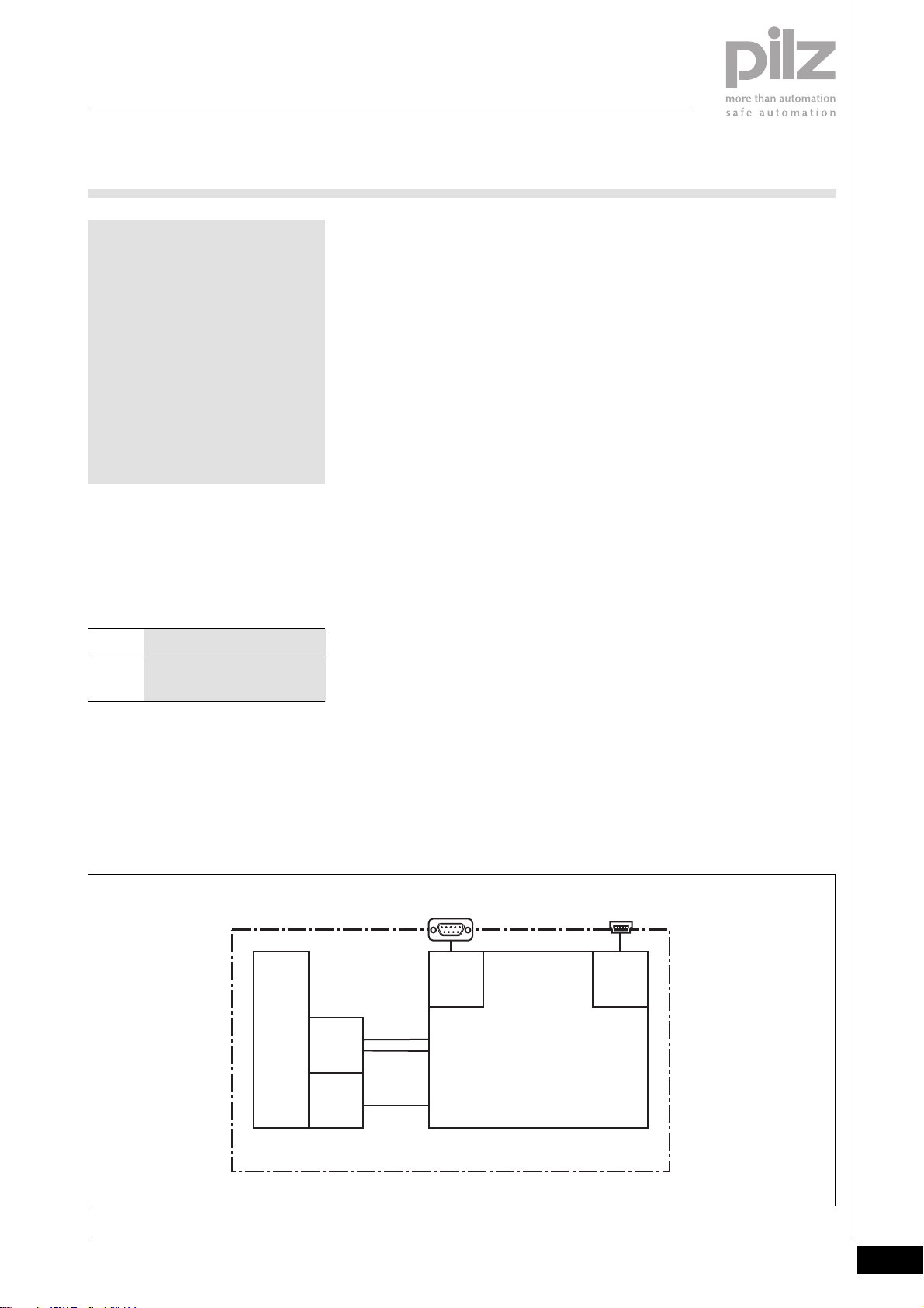
Block diagram
In progress
Mo du le Bus
Module
Supply
+ 5 V DC
Data
(FS)
1
659
Data
(FS)
USBSafetyBUS p
1
Firmware
5
Pilz GmbH & Co. KG, Sichere Automation, Felix-Wankel-Straße 2, 73760 Ostfildern, Germany
Telephone +49 711 3409-0, Telefax +49 711 3409-133, E-Mail: [email protected]
Status 01/05
2.1-1
Page 25
PSSuniversal
Head modules
PSSu H SB
Function description
` Module supply (5 VDC)
The electronics are supplied via
the module bus.
` SafetyBUS p
The system can be connected to
SafetyBUS p as a SafetyBUS p
subscriber via the SafetyBUS p
interface.
- SafetyBUS p interface: male 9pin D-SUB connector
“SafetyBUS p”
- Ability to connect the Pilz FO
coupler PSS SB SUB-D F0.
- Device address: can be set via
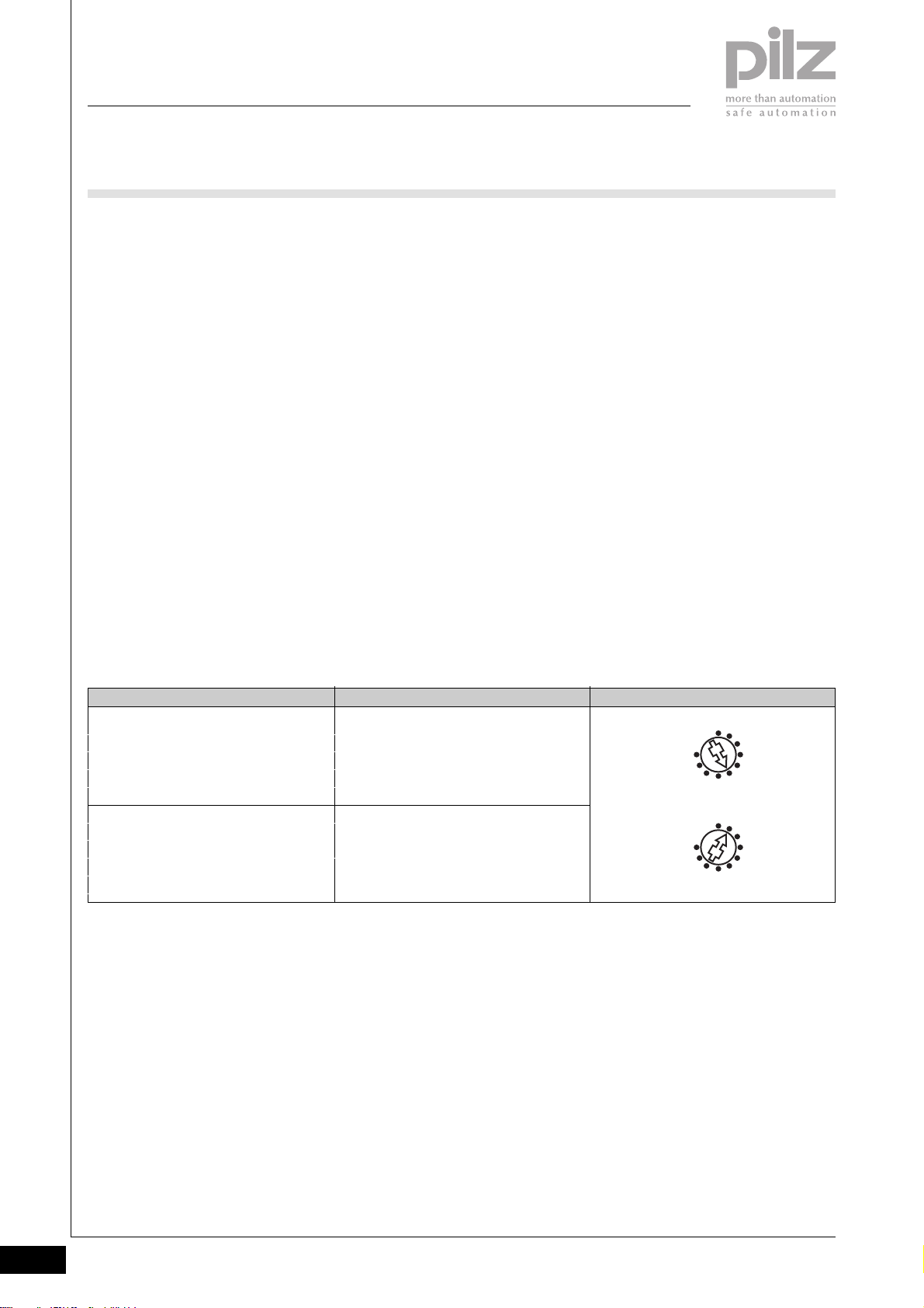
the two rotary switches “SB
ADDRESS”.
Valid device addresses:
32D ... 95D.
- SafetyBUS p status: displayed
via the LEDs “SB” and “I/O”.
Setting the device address for
SafetyBUS p
` USB
For commissioning and service
work, a PSSu system can be
connected to a PC via the USB
port.
- USB port:
Mini-B USB connector “USB”
- USB status: displayed via the
LED “USB”
Rotary switch “SB ADDRESS” Key
“x 10”
“x 1”
Setting the tens
Setting the units
Example: Device address 51
0
x 10
9
SB ADDRESS
x 1
9
3
6
0
3
6
D
2.1-2
Pilz GmbH & Co. KG, Sichere Automation, Felix-Wankel-Straße 2, 73760 Ostfildern, Germany
Telephone +49 711 3409-0, Telefax +49 711 3409-133, E-Mail: [email protected]
Status 01/05
Page 26
PSSuniversal
Head modules
PSSu H SB
System configuration for
SafetyBUS p
The system is configured using Pilz
configuration software.
Usb
SB
0
x 10
9
6
SB ADDRESS
0
x 1
9
6
Dev
I/O
3
3
Usb Dev
SB I/O
312 010
USB
1
VBUS
2
D -
3
D +
4
5
G N D
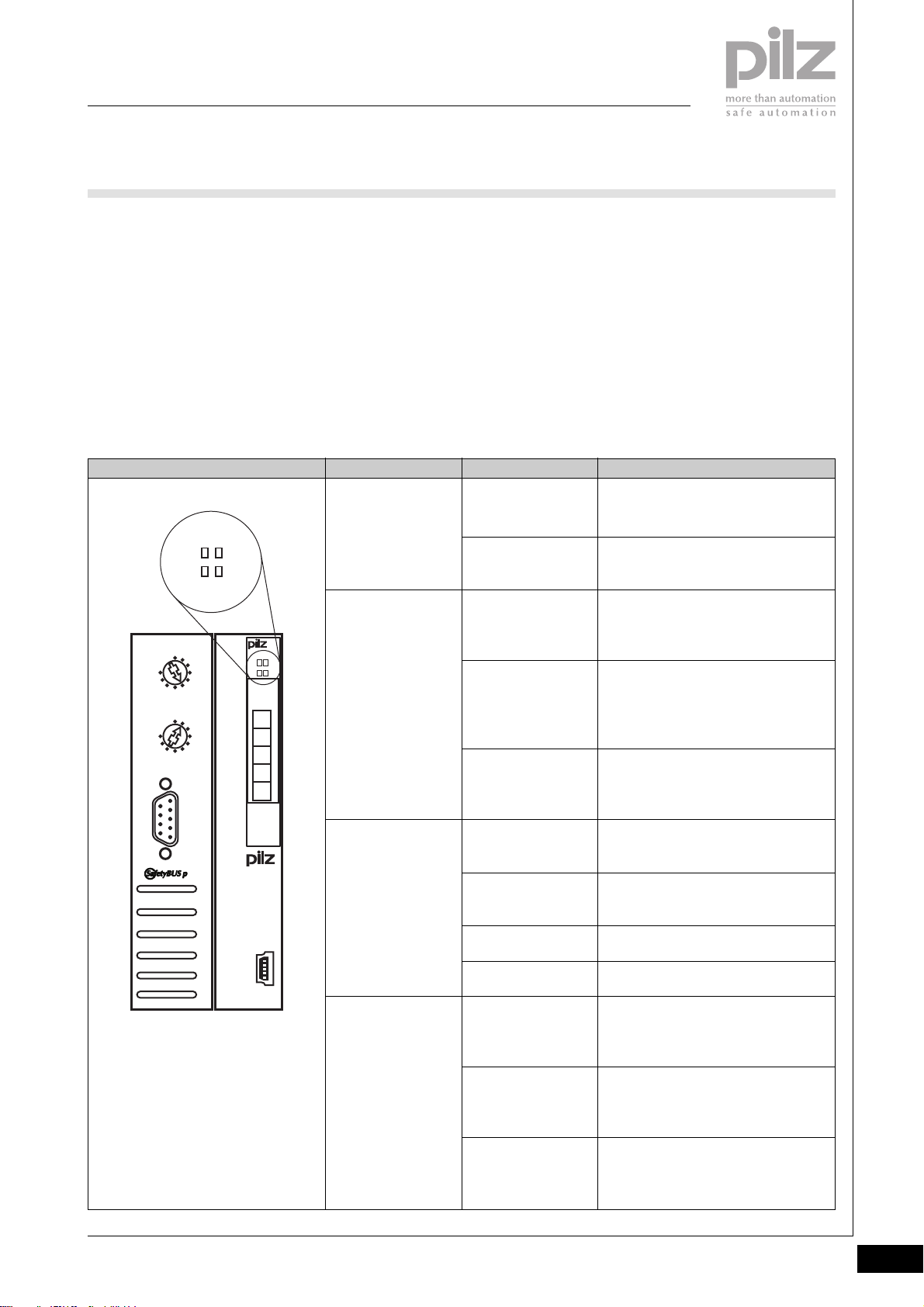
Diagnostics
` The module has various LEDs to
display
- System status
- SafetyBUS p status
- I/O-Group status (SafetyBUS p)
- USB status
(see table below)
LED KeyLED statusHead module
“Usb”
“SB”
Off
Lights green
Off
Flashes green
Lights green
` SafetyBUS p error reaction:
If an error occurs, all the outputs
in the affected I/O-Group are shut
down safely and the I/O-Group
switches to a STOP condition. The
error is entered in the head
module’s error buffer.
2
No data is being exchanged via the
USB port
Data is being exchanged via the USB
port
No contact with SBp
- SBp wiring is faulty or
- MD is not in operation
There is contact with SBp, but the MD
does not recognise the SBp device
- SBp device address is faulty or
- SBp configuration is faulty
There is contact with SBp, the
connection to the MD is running
correctly
PSSu H
SB
USB
Pilz GmbH & Co. KG, Sichere Automation, Felix-Wankel-Straße 2, 73760 Ostfildern, Germany
Telephone +49 711 3409-0, Telefax +49 711 3409-133, E-Mail: [email protected]
“Dev”
“I/O”
Off
Lights green
Lights red
Flashes red
Off
Flashes green
Lights green
A PSSu system error is preventing the
PSSu system from starting up
The PSSu system is operating without
error
A PSSu module error has occurred
A PSSu periphery error has occurred
All the I/O-Groups configured on the
SBp device are in a STOP condition
One of the I/O-Groups configured on
the SBp device is in a STOP condition
All the I/O-Groups configured on the
SBp device are in a RUN condition
Status 01/05
2.1-3
Page 27
PSSuniversal
Head modules
PSSu H SB
Head module
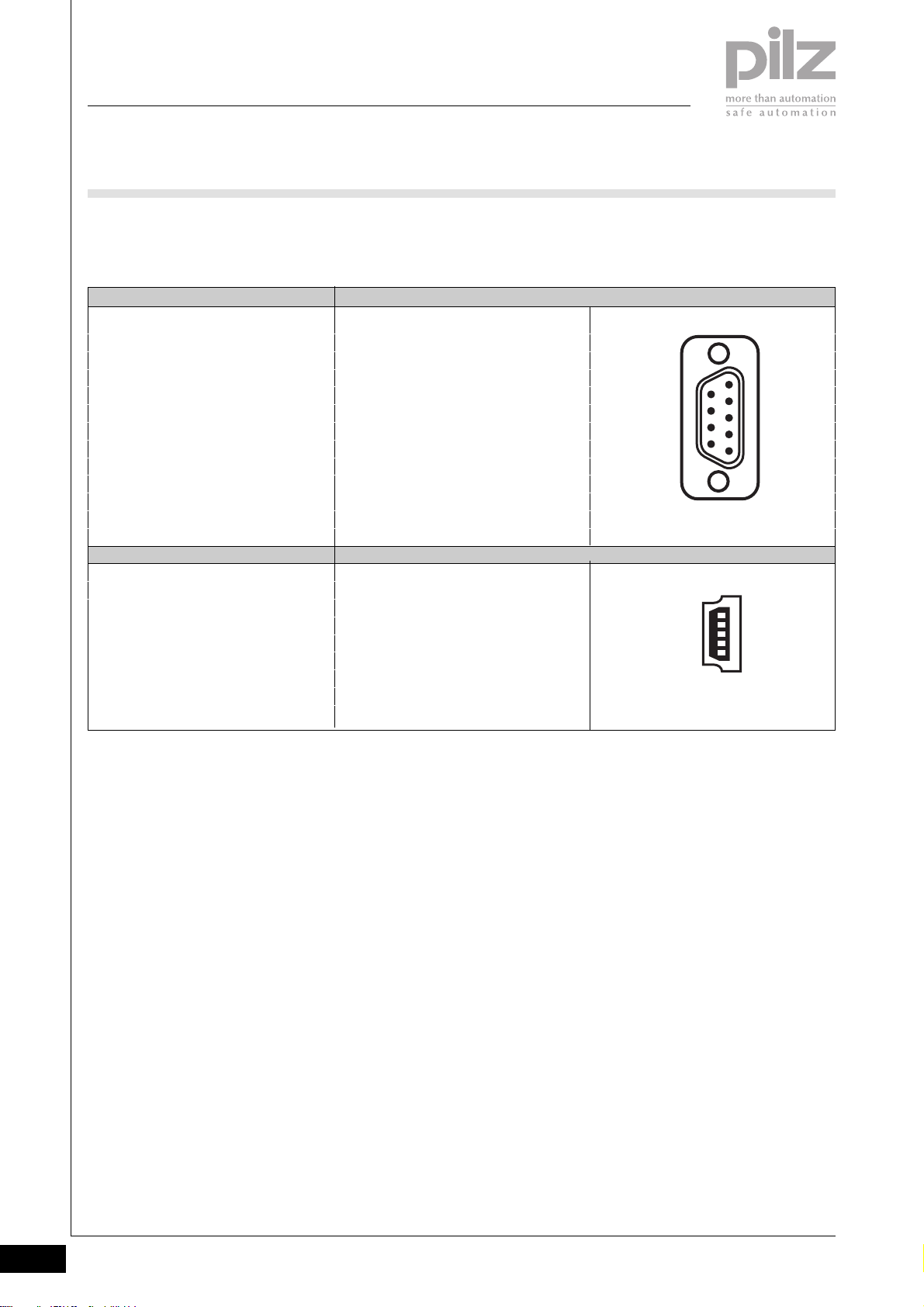
` Interface assignment
SafetyBUS p Assignment
Male 9-pin D-SUB connector
USB
Mini-B USB connector
1: n.c.
2: CAN_L (brown)
3: CAN_GND (white)
4: n.c.
5: CAN_SHLD
6: n.c.
7: CAN_H (green)
8: Supply voltage for
Pilz FO coupler
9: n.c.
n.c. = not connected
Assignment
1: VBUS +5 VDC
2: D- USB Data3: D+ USB Data+
4: n.c.
5: GND Ground
n.c. = not connected
6
9
1
5
1
5
2.1-4
Pilz GmbH & Co. KG, Sichere Automation, Felix-Wankel-Straße 2, 73760 Ostfildern, Germany
Telephone +49 711 3409-0, Telefax +49 711 3409-133, E-Mail: [email protected]
Status 01/05
Page 28
PSSuniversal
Head modules
PSSu H SB
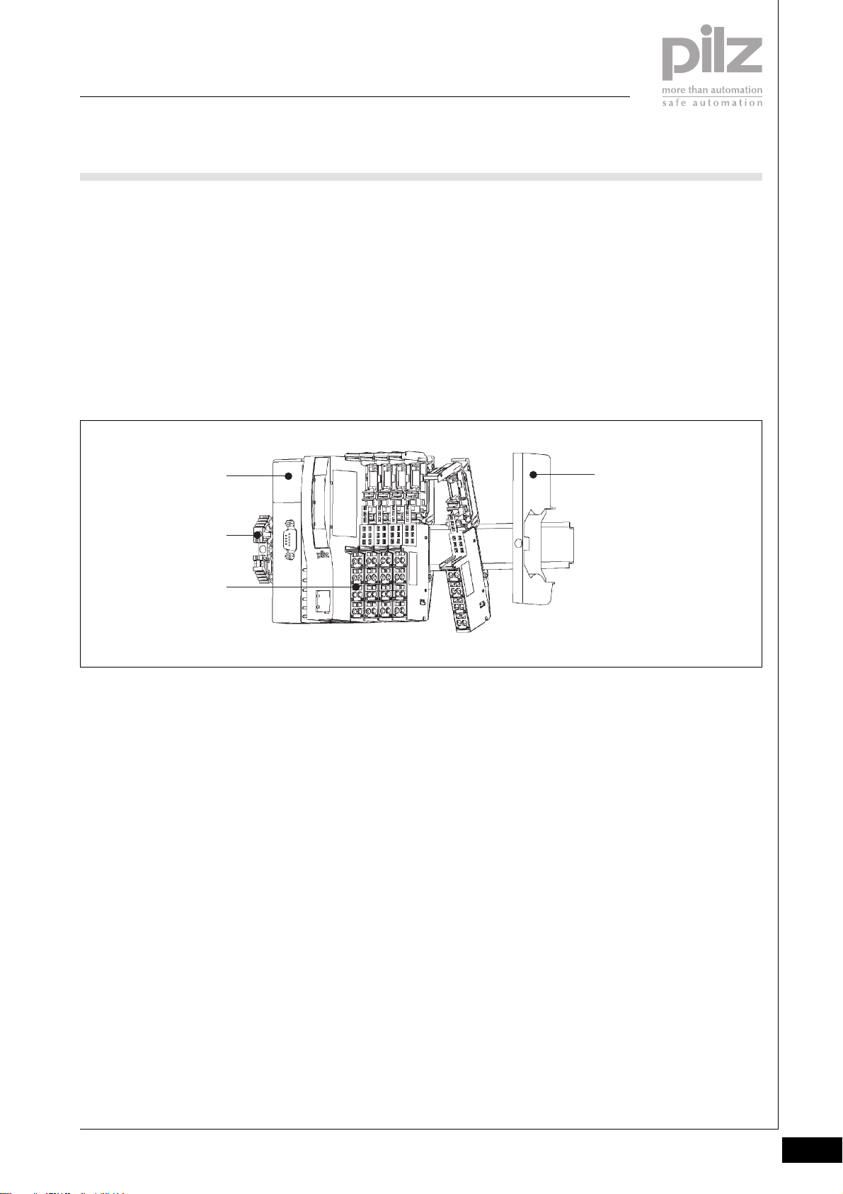
Installation
` Horizontal installation is
preferable!
Vertical installation is possible, but
involves restrictions in terms of
temperature and vibration
resistance.
` Attach the head module to the
mounting rail as the first module
on the system and lock into
position [1].
[1]
[2]
[3]
` Install the appropriate end bracket
on the mounting rail to the left of
the head module [2].
` Always attach an appropriate
supply voltage module to the
mounting rail as the first module
to the right of the head module
and then lock into position [3].
` Secure the final module on the
mounting rail with the appropriate
fixing bracket [4].
2
[4]
Pilz GmbH & Co. KG, Sichere Automation, Felix-Wankel-Straße 2, 73760 Ostfildern, Germany
Telephone +49 711 3409-0, Telefax +49 711 3409-133, E-Mail: [email protected]
Status 01/05
2.1-5
Page 29
PSSuniversal
Head modules
PSSu H SB
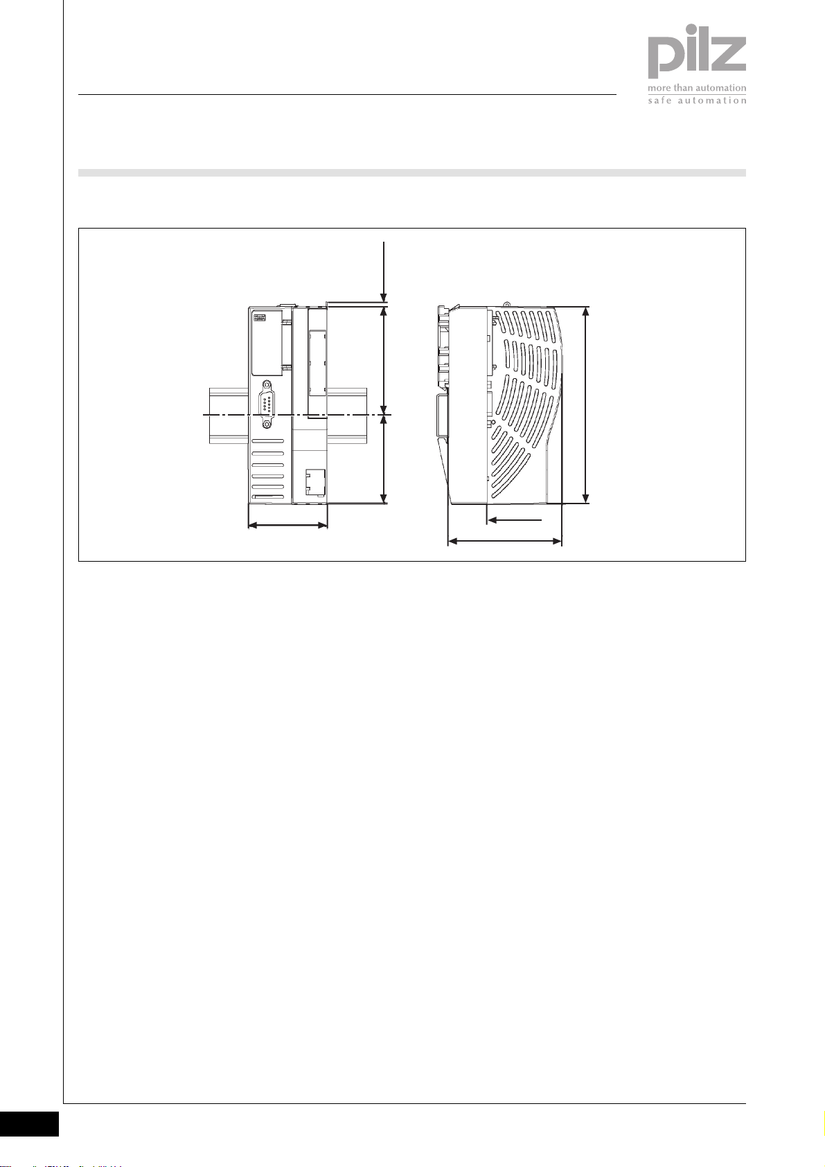
Dimensions
2,8 mm
69,2 mm56,4 mm
125,6 mm
50,2 mm
Using this data sheet
This data sheet is only intended for
use during configuration.
NOTICE
Please refer to the operating
manual during commissioning and
operation.
21,6 mm
72,6 mm
2.1-6
Pilz GmbH & Co. KG, Sichere Automation, Felix-Wankel-Straße 2, 73760 Ostfildern, Germany
Telephone +49 711 3409-0, Telefax +49 711 3409-133, E-Mail: [email protected]
Status 01/05
Page 30
PSSuniversal
Head modules
PSSu H SB
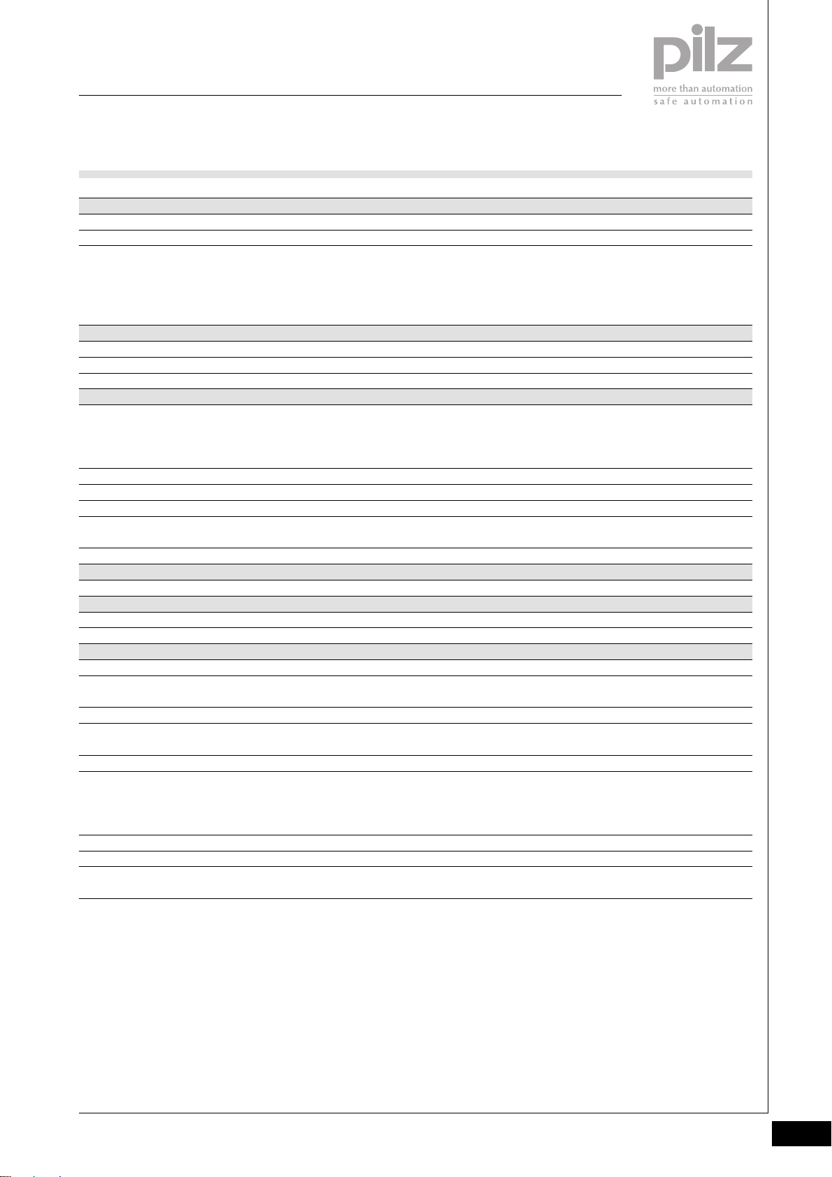
Technical details
Function
Application range
Electrical data
Supply voltage from module supply
Current consumption from module supply
Power consumption
SafetyBUS p
Application range
Device address
Transmission rate
Cable runs
Transmission type
Connection
USB
Connection
Mechanical data
Dimensions (H x W x D)
Weight
Environmental data
Protection type (EN 60529, 02/00)
Ambient temperature
(EN 60068-2-14, 11/99)
Storage temperature (EN 60068-2-1/-2, 07/94)
Climatic suitability
(EN 60068-2-78, 10/01)
Condensation
Vibration (EN 60068-2-6, 04/95)
Shock (EN 60068-2-27, 03/93)
Continuous shock (EN 60068-2-29, 04/93)
EMC
PSSu H SB
Modular I/O system for decentralised applications
Failsafe applications conforming to
EN 954-1, 03/97,
DIN V 19 250, 05/94,
DIN VDE 0116, 09/97,
EN IEC 61508, 12/98
5 VDC
≤ 300 mA
1.5 W
Failsafe applications conforming to
EN 954-1, 03/97,
DIN V 19 250, 05/94,
DIN VDE 0116, 09/97
32D ... 95D, selectable
Max. 500 kBit/s
max. 3,500 m
Differential two-wire cable,
Fibre-optic cable via fibre-optic coupler
Male 9-pin D-SUB connector
Mini-B USB connector
128.4 x 50.2 x 72.6 mm
180 g
IP20
0 ... +60 °C
-25 ... +70 °C
93 % r.h. at 40 °C
Not permitted
Frequency range: 10 ... 57 Hz
Amplitude: 0.075 mm
Frequency range: 57 ... 150 Hz
Acceleration: 1g
15g, 11 ms
10g, 16 ms
EN 61000-6-2, 08/02
EN 61000-6-4, 08/02
2
Pilz GmbH & Co. KG, Sichere Automation, Felix-Wankel-Straße 2, 73760 Ostfildern, Germany
Telephone +49 711 3409-0, Telefax +49 711 3409-133, E-Mail: [email protected]
Status 01/05
2.1-7
Page 31
PSSuniversal
Head modules
PSSu H SB
Order reference
Description
PSSu H SB
(Head module with SafetyBUS p interface)
Order reference for accessories
Description
Operating manual in German
Operating manual in English
Operating manual in French
Operating manual in Spanish
Operating manual in Italian
Operating manual in Dutch
Order no.
312 010
Order no.
In progress
In progress
In progress
In progress
In progress
In progress
2.1-8
Pilz GmbH & Co. KG, Sichere Automation, Felix-Wankel-Straße 2, 73760 Ostfildern, Germany
Telephone +49 711 3409-0, Telefax +49 711 3409-133, E-Mail: [email protected]
Status 01/05
Page 32
PSSuniversal
Head modules
PSSu H SB DP
PSSu H SB DP
not shown
Head module to connect a PSSu
type system to SafetyBUS p and
PROFIBUS-DP simultaneously.
Suitable for safety-related and nonsafety-related functions.
Approvals
PSSu H SB DP
Module features
` SafetyBUS p interface for
switching failsafe inputs/outputs
via SafetyBUS p
` PROFIBUS interface for switching
- Standard inputs/outputs via
PROFIBUS-DP and
- Failsafe outputs via the local
enable principle
` USB port for PC connection for
- Commissioning and service
` LED indicators for:
- System status
- SafetyBUS p status
- USB status
- PROFIBUS interface status
` Electronic modules suitable for
use for input/output:
- All failsafe modules
(identifier: PSSu E F ...)
- All standard modules
(identifier: PSSu E S ...)
Module description
The module meets the requirements
of EN IEC 61508 and EN 954-1
Category 4. The module may be
used to connect the system to
` SafetyBUS p
` PROFIBUS-DP
Safety features
The module meets the following
safety requirements:
` Watchdog for life monitoring
` Protection against over-
temperature
` Safe voltage monitoring
2
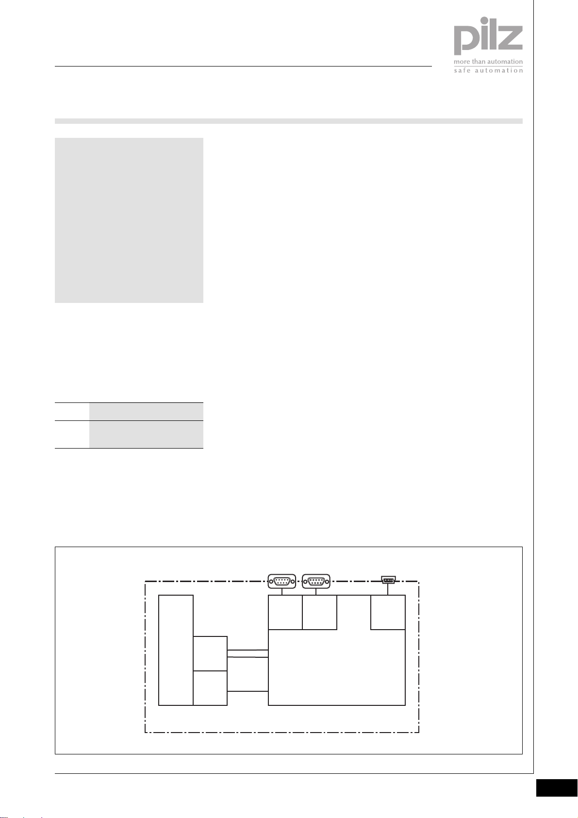
Block diagram
In progress
Mo du le Bus
Module
Supply
+ 5 V DC
Data
(ST + FS)
1
659
Data
(FS)
PROFIBUS DP
5
916
Data
(ST)
USBSafetyBUS p
1
Firmware
5
Pilz GmbH & Co. KG, Sichere Automation, Felix-Wankel-Straße 2, 73760 Ostfildern, Germany
Telephone +49 711 3409-0, Telefax +49 711 3409-133, E-Mail: [email protected]
Status 01/05
2.1-9
Page 33
PSSuniversal
Head modules
PSSu H SB DP
Function description
` Module supply (5 VDC)
The electronics are supplied via
the module bus.
` SafetyBUS p
The system can be connected to
SafetyBUS p as a SafetyBUS p
subscriber via the SafetyBUS p
interface.
- SafetyBUS p interface: male
9-pin D-SUB connector
“SafetyBUS p”
- Ability to connect the Pilz FO
coupler PSS SB SUB-D F0.
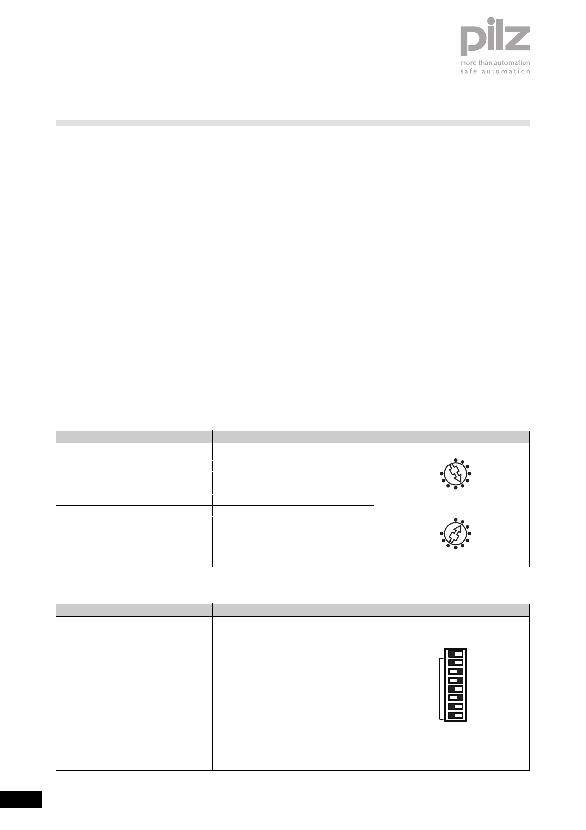
- Device address: can be set via
the two rotary switches “SB
ADDRESS”.
Valid device addresses:
32D ... 95D.
- SafetyBUS p status: displayed
via the LEDs “SB” and “I/O”
Setting the device address for
SafetyBUS p
` PROFIBUS
The system can be connected to
PROFIBUS as a PROFIBUS-DP
Slave via the PROFIBUS interface.
The basic functions of
communication with PROFIBUSDP conform to EN 50170.
- PROFIBUS interface: female
9-pin D-SUB connector
“PROFIBUS-DP”
- Ability to connect an FO
coupler for PROFIBUS-DP.
- Station address can be set via
the binary coded DIP switch
“ADDRESS”
Valid station addresses:
0D ... 125
- PROFIBUS-DP interface status:
D
displayed via the LEDs “RUN”
and “BF”
` USB
For commissioning and service
work, a PSSu system can be
connected to a PC via the USB
port.
- USB port:
Mini-B USB connector “USB”
- USB status: displayed via the
LED “USB”
Rotary switch “SB ADDRESS” Key
“x 10”
“x 1”
Setting the station address for
PROFIBUS
DIP switch “ADDRESS” Key
“- -”
“64”
“32”
“16”
“8”
“4”
“2”
“1”
Setting the tens
Setting the units
A station address is set via a combination
of the relevant binary coded switches.
OFF ON
Not assigned
064
032
016
08
04
02
01
D
D
D
D
(26)
D
(25)
D
(24)
D
(23)
(22)
(21)
(20)
Example: Device address 51
0
x 10
9
3
6
SB ADDRESS
0
x 1
9
3
6
Example: Station address 52
OFF
ON
- 64
32
16
ADDRESS
D
D
8
4
2
1
2.1-10
Pilz GmbH & Co. KG, Sichere Automation, Felix-Wankel-Straße 2, 73760 Ostfildern, Germany
Telephone +49 711 3409-0, Telefax +49 711 3409-133, E-Mail: [email protected]
Status 01/05
Page 34
PSSuniversal
Head modules
PSSu H SB DP
System configuration for
SafetyBUS p
The system is configured using Pilz
configuration software.
Parameter settings for PROFIBUS-DP
The parameter settings for the
PROFIBUS-DP Slave conform to the
guidelines of the PROFIBUS User
Group (PNO).
Dev
I/O
3
3
Usb Dev
SB I/O
312 025
USB
1
VBUS
2
D -
3
D +
4
5
G N D
PSSu H
SB DP
Run
BF
OFF
ON
ADDRESS
PROFIBUS DP
- 64
32
16
8
4
2
1
Usb
SB
0
x 10
9
6
SB ADDRESS
0
x 1
9
6
Diagnostics
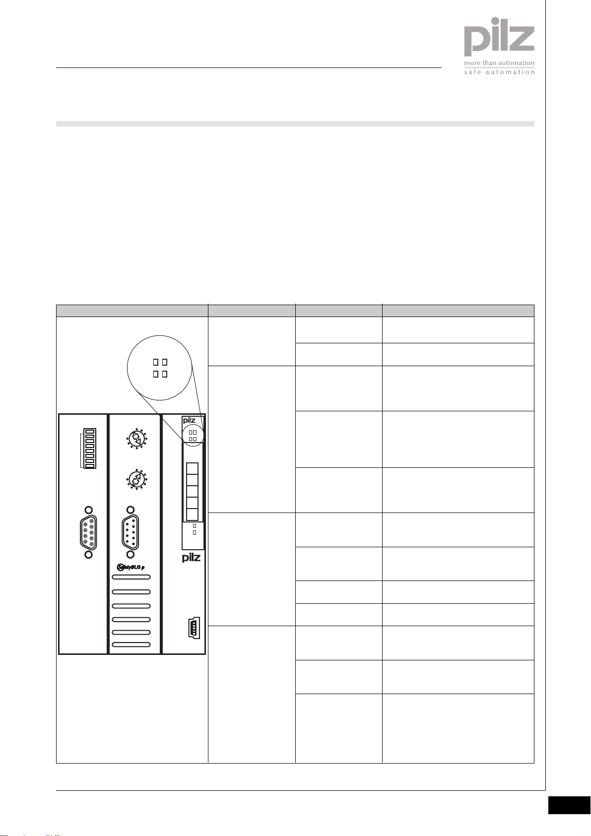
` The module has various LEDs to
display
- System status
- SafetyBUS p status
- I/O-Group status (SafetyBUS p)
- USB status
- PROFIBUS interface status
(see tables below)
LED
“Usb”
“SB”
“Dev”
LED statusHead module
Off
Lights green
Off
Flashes green
Lights green
Off
Lights green
` SafetyBUS p error reaction:
If an error occurs, all the outputs
in the affected I/O-Group are shut
down safely and the I/O-Group
switches to a STOP condition. The
error is entered in the head
module’s error buffer.
` PROFIBUS-DP error reaction:
The error reaction conforms to the
guidelines of the PROFIBUS User
Group (PNO).
2
Key
No data is being exchanged via the
USB port
Data is being exchanged via the USB
port
No contact with SBp
- SBp wiring is faulty or
- MD is not in operation
There is contact with SBp, but the MD
does not recognise the SBp device
- SBp device address is faulty or
- SBp configuration is faulty
There is contact with SBp, the
connection to the MD is running
correctly
A PSSu system error is preventing the
PSSu system from starting up
The PSSu system is operating without
error
A PSSu module error has occurred
A PSSu periphery error has occurred
All the I/O-Groups configured on the
USB
“I/O”
Lights red
Flashes red
Off
SBp device are in a STOP condition
Flashes green
One of the I/O-Groups configured on
the SBp device is in a STOP condition
Lights green
All the I/O-Groups configured on the
SBp device are in a RUN condition
Pilz GmbH & Co. KG, Sichere Automation, Felix-Wankel-Straße 2, 73760 Ostfildern, Germany
Telephone +49 711 3409-0, Telefax +49 711 3409-133, E-Mail: [email protected]
Status 01/05
2.1-11
Page 35
PSSuniversal
Head modules
PSSu H SB DP
OFF
ON
ADDRESS
PROFIBUS DP
- 64
32
16
8
4
2
1
0
x 10
9
6
SB ADDRESS
0
x 1
9
6
3
3
Run
BF
Usb Dev
SB I/O
PSSu H
SB DP
USB
312 025
USB
1
VBUS
2
D -
3
D +
4
5
G N D
Run
BF
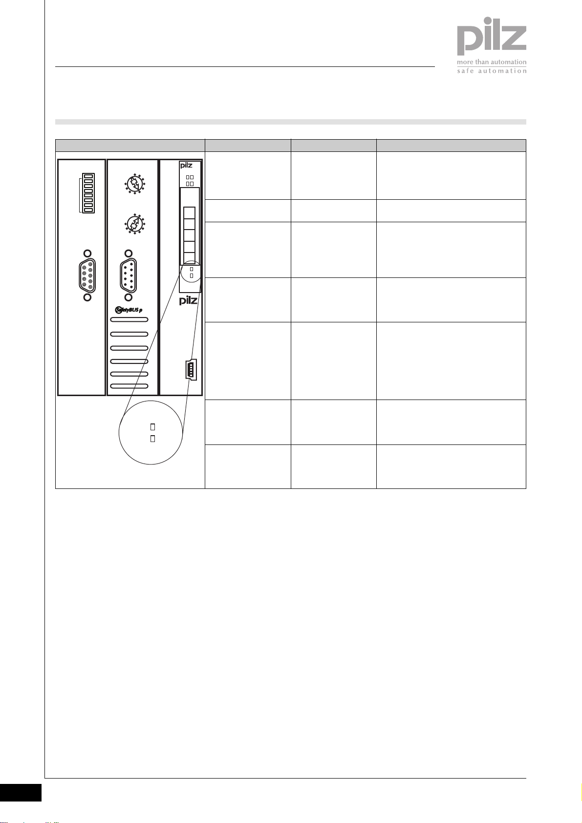
LED status “BF”
Off
Lights red
Flashes red
Flashes red
Flashes red
Off
Off
LED status “Run”Head module
Off
Off
Off
Lights green
Flashes green
Flashes green
Lights green
Key
No supply voltage or
PROFIBUS interface start-up is not yet
complete
Bus error on PROFIBUS
PROFIBUS station address is invalid
Remedy:
Set a valid PROFIBUS station address
PROFIBUS diagnostics being run prior
to PROFIBUS data transfer
Fatal error (PROFIBUS)
Remedy:
- Restart the head module or
- Reset the head module by switching
the supply to the head module off/on
Static PROFIBUS diagnostics being run
during data transfer.
Data is being exchanged between the
PROFIBUS interface and the
PROFIBUS Master
2.1-12
Pilz GmbH & Co. KG, Sichere Automation, Felix-Wankel-Straße 2, 73760 Ostfildern, Germany
Telephone +49 711 3409-0, Telefax +49 711 3409-133, E-Mail: [email protected]
Status 01/05
Page 36
PSSuniversal
Head modules
PSSu H SB DP
Head module
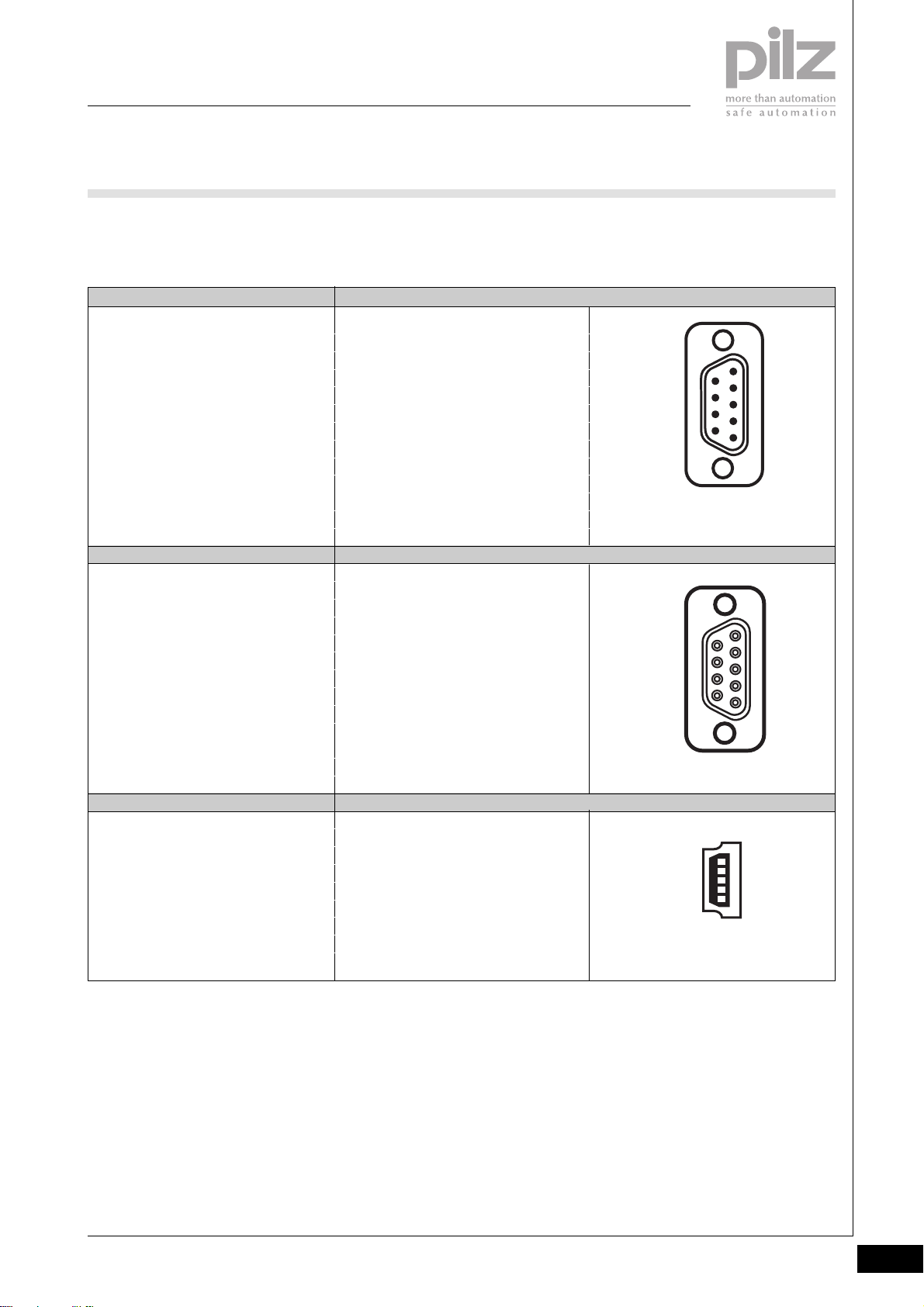
` Interface assignment
SafetyBUS p Assignment
Male 9-pin D-SUB connector
PROFIBUS-DP
Female 9-pin D-SUB connector
conforms to the guidelines of the
PROFIBUS User Group (PNO).
1: n.c.
2: CAN_L (brown)
3: CAN_GND (white)
4: n.c.
5: CAN_SHLD
6: n.c.
7: CAN_H (green)
8: Supply voltage for
Pilz FO coupler
9: n.c.
n.c. = not connected
Assignment
1: n.c.
2: n.c.
3: RxD/TxD-P (B-line)
4: CNTR-P (RTS)
5: DGND (GND ext.)
6: VP (+5 V ext.)
7: n.c.
8: RxD/TxD-N (A-line)
9: n.c.
n.c. = not connected
6
9
9
6
1
5
2
5
1
USB
Mini-B USB connector
Pilz GmbH & Co. KG, Sichere Automation, Felix-Wankel-Straße 2, 73760 Ostfildern, Germany
Telephone +49 711 3409-0, Telefax +49 711 3409-133, E-Mail: [email protected]
Assignment
1: VBUS +5 VDC
2: D- USB Data3: D+ USB Data+
4: n.c.
5: GND Ground
n.c. = not connected
1
5
Status 01/05
2.1-13
Page 37
PSSuniversal
Head modules
PSSu H SB DP
Installation
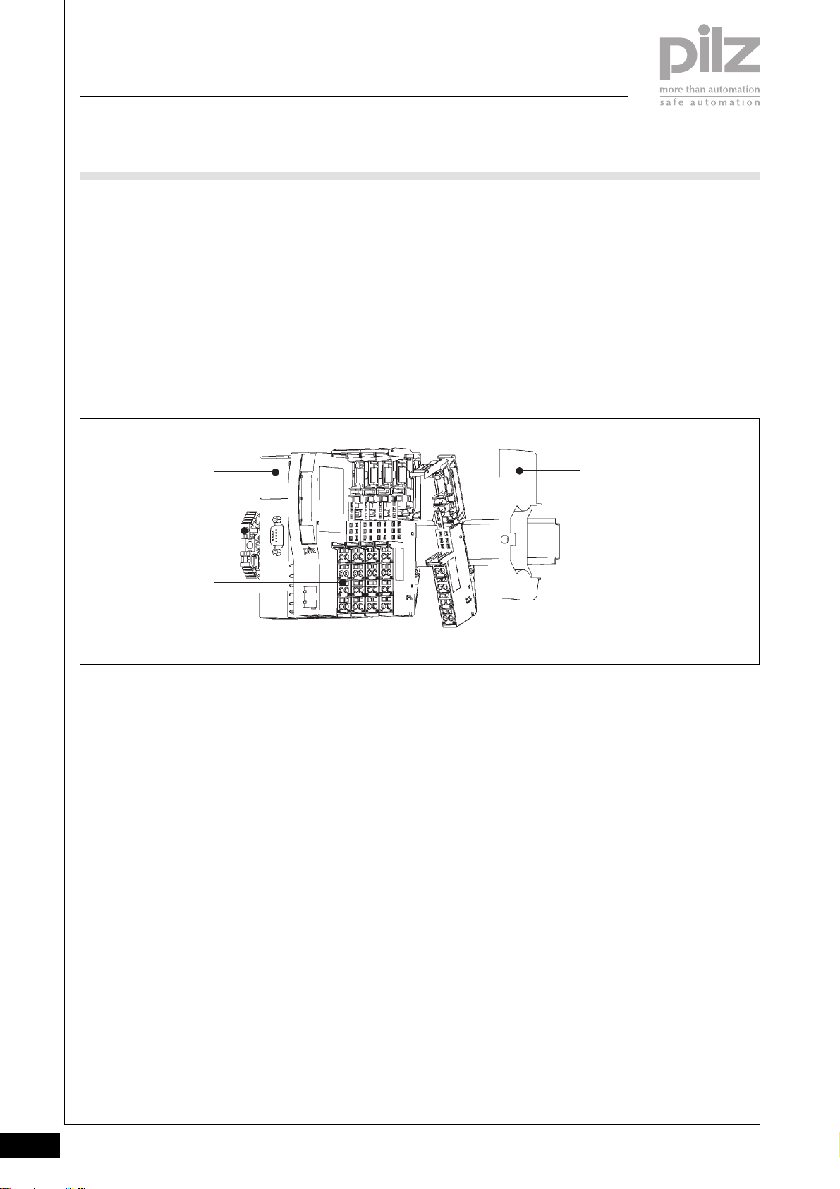
` Horizontal installation is
preferable!
Vertical installation is possible, but
involves restrictions in terms of
temperature and vibration
resistance.
` Attach the head module to the
mounting rail as the first module
on the system and lock into
position [1].
[1]
[2]
[3]
` Install the appropriate end bracket
on the mounting rail to the left of
the head module [2].
` Always attach an appropriate
supply voltage module to the
mounting rail as the first module
to the right of the head module
and then lock into position [3].
` Secure the final module on the
mounting rail with the appropriate
fixing bracket [4].
[4]
2.1-14
Pilz GmbH & Co. KG, Sichere Automation, Felix-Wankel-Straße 2, 73760 Ostfildern, Germany
Telephone +49 711 3409-0, Telefax +49 711 3409-133, E-Mail: [email protected]
Status 01/05
Page 38
PSSuniversal
Head modules
PSSu H SB DP
Dimensions
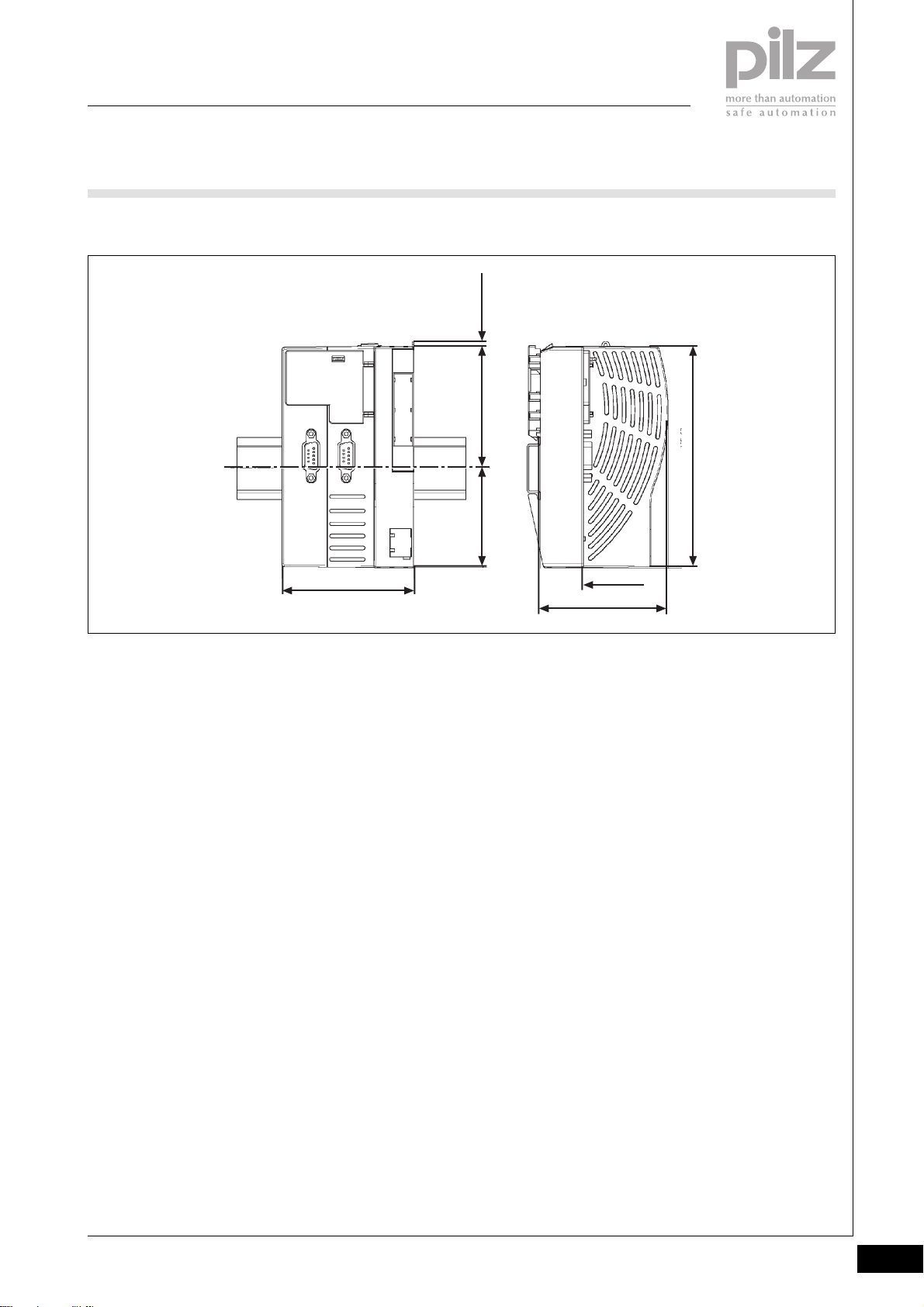
2,8 mm
Using this data sheet
This data sheet is only intended for
use during configuration.
NOTICE
Please refer to the operating
manual during commissioning and
operation.
75,2 mm
69,2 mm
56,4 mm
2
125,6 mm
21,6 mm
72,6 mm
Pilz GmbH & Co. KG, Sichere Automation, Felix-Wankel-Straße 2, 73760 Ostfildern, Germany
Telephone +49 711 3409-0, Telefax +49 711 3409-133, E-Mail: [email protected]
Status 01/05
2.1-15
Page 39
PSSuniversal
Head modules
PSSu H SB DP
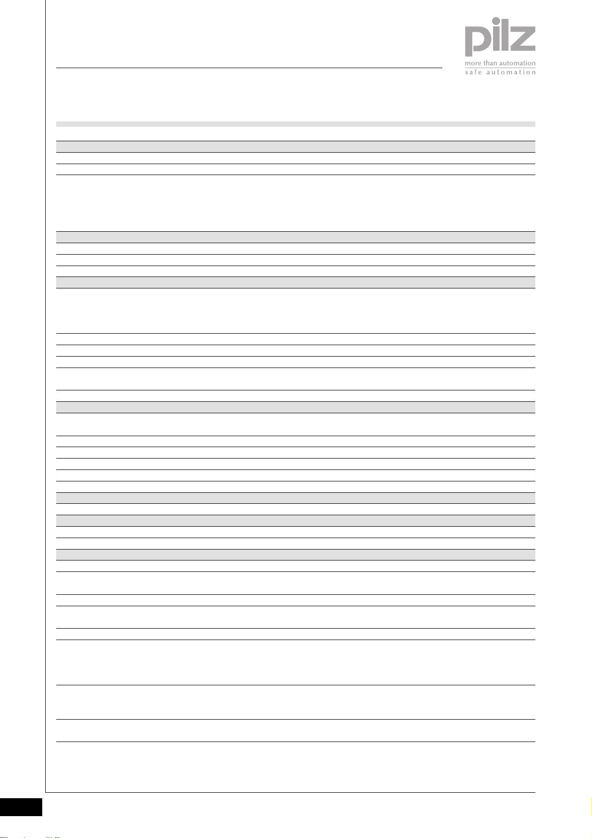
Technical details
Function
Application range
Electrical data
Supply voltage
Current consumption
Power consumption
SafetyBUS p
Application range
Device address
Transmission rate
Cable runs
Transmission type
Connection
PROFIBUS-DP
Application range
Device type
Status display
Station address
Transmission rate
Connection
USB
Connection
Mechanical data
Dimensions (H x W x D)
Weight
Environmental data
Protection type (EN 60529, 02/00)
Ambient temperature
(EN 60068-2-14, 11/99)
Storage temperature (EN 60068-2-1/-2, 07/94)
Climatic suitability
(EN 60068-2-78, 10/01)
Condensation
Vibration (EN 60068-2-6, 04/95)
Shock
EN 60068-2-27, 03/93
EN 60068-2-29, 04/93
EMC
PSSu H SB
Modular I/O system for decentralised applications
Failsafe applications conforming to
EN 954-1, 03/97,
DIN V 19 250, 05/94,
DIN VDE 0116, 09/97,
EN IEC 61508, 12/98
From module supply: 5 VDC
From module supply: ≤ 500 mA
2.5 W
Failsafe applications conforming to
EN 954-1, 03/97,
DIN V 19 250, 05/94,
DIN VDE 0116, 09/97
32D ... 95D, selectable
Max. 500 kBit/s
max. 3,500 m
Differential two-wire cable,
Fibre-optic cable via fibre-optic coupler
Male 9-pin D-SUB connector
Non-safety-related applications,
failsafe applications in accordance with the local enable principle
Slave
LED
0 ... 125D, selectable
Max. 12 MBit/s
Female 9-pin D-SUB connector
Mini-B USB connector
128.4 x 75.2 x 72.6 mm
195 g
IP20
0 ... +60 °C
-25 ... +70 °C
93 % r.h. at 40 °C
Not permitted
Frequency range: 10 ... 57 Hz
Amplitude: 0.075 mm
Frequency range: 57 ... 150 Hz
Acceleration: 1g
15g, 11 ms
10g, 16 ms
EN 61000-6-2, 08/02
EN 61000-6-4, 08/02
2.1-16
Pilz GmbH & Co. KG, Sichere Automation, Felix-Wankel-Straße 2, 73760 Ostfildern, Germany
Telephone +49 711 3409-0, Telefax +49 711 3409-133, E-Mail: [email protected]
Status 01/05
Page 40
PSSuniversal
Head modules
PSSu H SB DP
Order reference
Description
PSSu H SB DP
(Head module with SafetyBUS p interface and
PROFIBUS-DP interface)
Order reference for accessories
Description
Operating manual in German
Operating manual in English
Operating manual in French
Operating manual in Spanish
Operating manual in Italian
Operating manual in Dutch
Order no.
312 025
Order no.
In progress
In progress
In progress
In progress
In progress
In progress
2
Pilz GmbH & Co. KG, Sichere Automation, Felix-Wankel-Straße 2, 73760 Ostfildern, Germany
Telephone +49 711 3409-0, Telefax +49 711 3409-133, E-Mail: [email protected]
Status 01/05
2.1-17
Page 41

PSSuniversal
Head modules
PSSu H SB DP
Notes
2.1-18
Pilz GmbH & Co. KG, Sichere Automation, Felix-Wankel-Straße 2, 73760 Ostfildern, Germany
Telephone +49 711 3409-0, Telefax +49 711 3409-133, E-Mail: [email protected]
Status 01/05
Page 42
PSSuniversal
Supply voltage
PSSu E F PS
PSSu E F PS
not shown
Electronic module to provide the
system with the module supply,
periphery supply and C-rail supply.
Approvals
PSSu E F PS
In progress
Module features
` Housing width: 12.6 mm
(1 x grid width)
` Supply for max. 12 modules
` Separate 24 VDC infeed for
module supply (5 VDC)
` Separate 24 VDC infeed for
periphery supply (24 VDC)
` Infeed for C-rail supply (if
required)
` LED indicators for:
- Module supply status
- Periphery supply status
- Module error
` Application depends on which
base module is used
` Details of the base modules that
can be used are available under
“Base modules” and “Order
reference”.
Module description
The module meets the requirements
of EN IEC 61508 and EN 954-1
Category 4. It provides the supply
for the module supply and periphery
supply within the system.
` Supply module to refresh the
module supply and periphery
supply
` Supply module to form supply
groups
Safety features
The module meets the following
safety requirements:
` Protection against over-
temperature
` Module supply
- Integral voltage limitation
- Protection circuit for EMC
` Periphery supply
- Integral voltage monitoring
(exceeding upper/lower limit)
- Integral current monitoring
(exceeding upper/lower limit)
- Integral thermistor monitoring
` Diagnostic capabilities
2
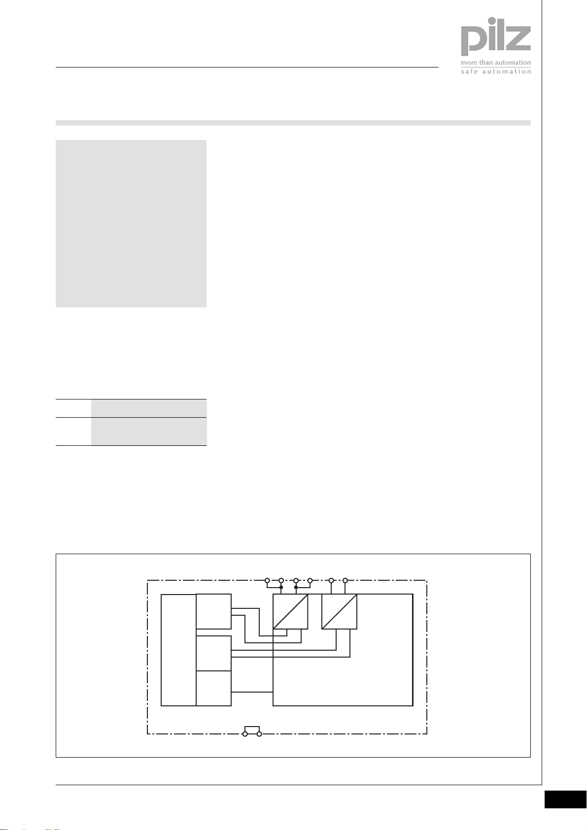
Block diagram
Mo dule Bus
Depending on which base module is
used, the module may be used as a:
` General supply module (first
module after the head module)
13 23
Periphery
Supply
+ 24 V DC
Module
Supply
+ 5 V DC
Data
(FS)
cross connection
14 24
=
=
11 2112 22
=
=
Pilz GmbH & Co. KG, Sichere Automation, Felix-Wankel-Straße 2, 73760 Ostfildern, Germany
Telephone +49 711 3409-0, Telefax +49 711 3409-133, E-Mail: [email protected]
Status 01/05
2.2-1
Page 43
PSSuniversal
Supply voltage
PSSu E F PS
Function description
` Using the module as the first
module after the head module
When the relevant base module is
used, the following supply can be
provided to the module bus:
- Module supply (5 VDC) for
head module (left-hand side)
- Module supply (+5 VDC) for
subsequent modules (righthand side)
- Periphery supply (24 VDC,
10 A) for subsequent modules
(right-hand side)
- C-rail supply for subsequent
modules (right-hand side)
` Using the module to refresh the
module supply and periphery
supply
When the relevant base module is
used, the connection to the
incoming (left-hand) module
supply, periphery supply and Crail is interrupted on the module
bus. The following supply is then
provided on the module bus for
subsequent (right-hand) modules:
- Module supply (5 VDC) for
subsequent modules (righthand side)
- Periphery supply (24 VDC,
10 A) for subsequent modules
(right-hand side)
- C-rail supply for subsequent
modules (right-hand side)
` Using the module to form supply
groups
When the relevant base module is
used, the connection to the
incoming (left-hand) module
supply, periphery supply and Crail is interrupted on the module
bus. The following supply is then
provided on the module bus for
subsequent (right-hand) modules:
- Module supply (5 VDC) for
subsequent modules (righthand side)
- Periphery supply (24 VDC,
10 A) for subsequent modules
(right-hand side)
- C-rail supply for subsequent
modules (right-hand side)
Each supply group requires its
own supply module.
` If galvanic isolation is required
between the module supply and
periphery supply, this is achieved
by feeding the voltages separately
(2 x 24 VDC). If this is not
required, one power supply is
sufficient for periphery supply and
module supply.
` It is not possible to switch off the
module supply if the lower voltage
limit is exceeded. However, there
will be a visual signal (LED “5 V”)
and a message will be sent to the
head module.
` It is not possible to switch off the
periphery supply if the upper/
lower limits of the monitored
parameters are exceeded.
However, there will be a visual
signal (LED “24 V”) and a
message will be sent to the head
module.
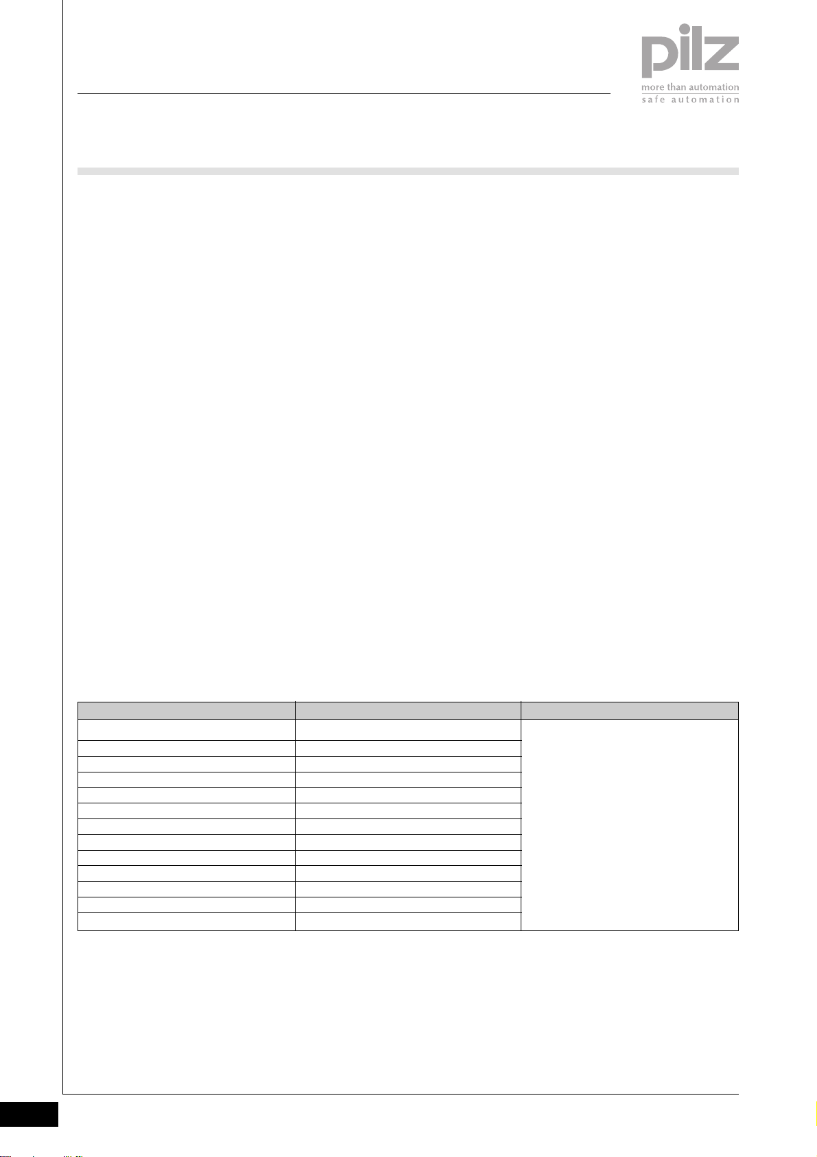
Overview of current consumption on
head modules and electronic
modules
Module
PSSu H SB
PSSu H SB DP
PSSu E S 4DI
PSSu E S 4DO 0.5
PSSu E S 2DO 2
PSSu E F 4DI
PSSu E F 4DO 0.5
PSSu E F 2DO 2
PSSu E F 4DI OZ 2
PSSu E F 2DOR 8
PSSu E F BSW
PSSu E F PS-P
PSSu E PD
Max. current consumption
≤ 300 mA
≤ 500 mA
≤ 25 mA
≤ 60 mA
≤ 50 mA
≤ 30 mA
≤ 75 mA
≤ 55 mA
≤ 35 mA
≤ 70 mA
≤ 220 mA
≤ 25 mA
0 mA
Explanation
The load on the module supply is
determined by the current consumption
of the head module and electronic
modules that are used.
A PSSu E F PS supply module provides
a max. module supply of 1.5 A.
If a heavier load arises, an additional
supply module must be used to refresh
the module supply.
2.2-2
Pilz GmbH & Co. KG, Sichere Automation, Felix-Wankel-Straße 2, 73760 Ostfildern, Germany
Telephone +49 711 3409-0, Telefax +49 711 3409-133, E-Mail: [email protected]
Status 01/05
Page 44
PSSuniversal
Supply voltage
PSSu E F PS
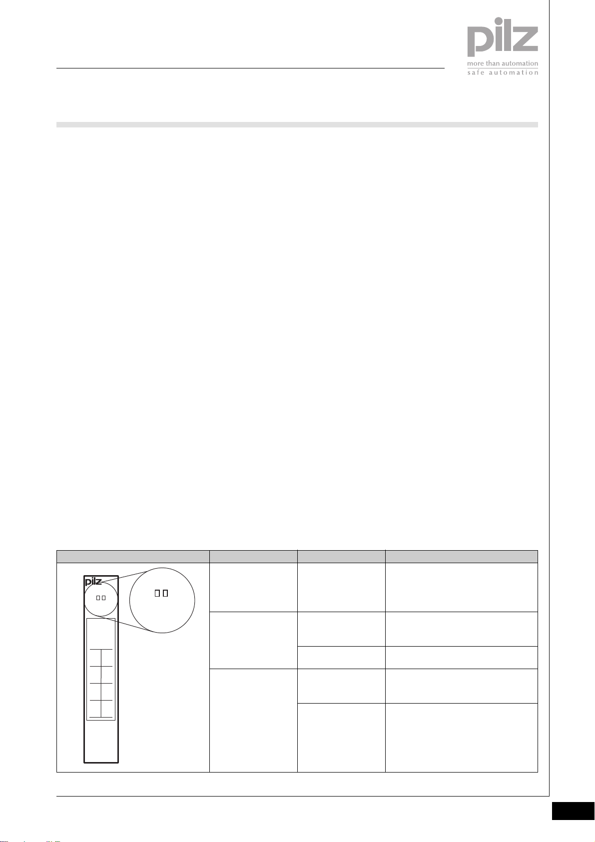
Module diagnostics
` The module has various LEDs to
display
- Module supply status (“5 V”)
-
Periphery supply status (“24 V”)
- Module error (“Err”)
(see table)
` Error reaction:
- Module supply error
If the lower voltage limit is
exceeded, a status message is
sent to the head module and
the “5 V” module LED (see
table)
- Periphery supply error
If the upper/lower limits of the
monitored parameters are
exceeded, a status message is
sent to the head module and
the “24 V” module LED (see
table)
- Module error
If a module error occurs (e.g.:
error at the inputs, error in
programming mode,
communication error), a status
message is sent to the head
module and the “Err” module
LED (see table)
- SafetyBUS p error
All the outputs in the affected
I/O-Group are shut down safely
and the I/O-Group switches to
a STOP condition. The error is
entered in the head module’s
error buffer.
Supply voltage
` The supply voltages for module
supply and periphery supply may
be in the range of +18 VDC ... +30
VDC. Safe operation cannot be
guaranteed outside this range.
` Safe electrical isolation must be
ensured for both the external 24 V
supplies. Failure to do so could
result in electric shock.
` Power supplies must conform to
EN 60950, 03/97, section 2.3, EN
60742, 9/95 or EN 50178, 10/97.
` To achieve the lowest possible
residual ripple (< ± 1.2 V), we
recommend that you install a
three-phase bridge rectifier or an
electronically regulated supply.
` If failsafe inputs are used, the
connection between “Ground”
(0 V periphery supply) and the
earth bar or earth fault monitor
must be in accordance with
relevant national regulations (e.g.
EN 60204-1, NFPA 79:17-7, NEC:
Article 250).
` On the module bus, the load
current of max. 10 A must not be
exceeded for the periphery
supply.
` A total current of max. 10 A must
not be exceeded on the C-rail.
Wiring
` Connect together the 0 V
connections on all the 24 V power
supplies and earth the 0 V supply
at a single point.
` The connection of the 0 V supply
to the central earth bar or earth
fault monitor must be in accordance with relevant national
regulations (e.g. EN 60204-1,
NFPA 79:17-7, NEC: Article 250).
` Minimum range for cable cross
sections on connection terminals
in mm2, in accordance with EN
61131-2, 07/00:
- Power supply:
1.5 (AWG16) ... 2.5 (AWG12)
- Functional earth:
1.5 (AWG16) ... 2.5 (AWG12)
` Use copper wiring.
2
LED KeyLED statusElectronic module
Err
Err
5 V 24 V
312190
11 21
120V22
13 23
24V 24V
14C24
PSSu E F
P S
Pilz GmbH & Co. KG, Sichere Automation, Felix-Wankel-Straße 2, 73760 Ostfildern, Germany
Telephone +49 711 3409-0, Telefax +49 711 3409-133, E-Mail: [email protected]
5V 24V
0V24V
0V
C
Err
24 V
5 V
Lights red
Off
Lights green
Off
Lights green
Module error
(e.g.: error at the inputs, error in
programming mode, communication
error)
No supply voltage or
error in the supply voltage
for periphery supply
Supply voltage for periphery supply is
error-free
No supply voltage or
error in the supply voltage
for module supply
Supply voltage for module supply is
error-free
Status 01/05
2.2-3
Page 45
PSSuniversal
Supply voltage
PSSu E F PS
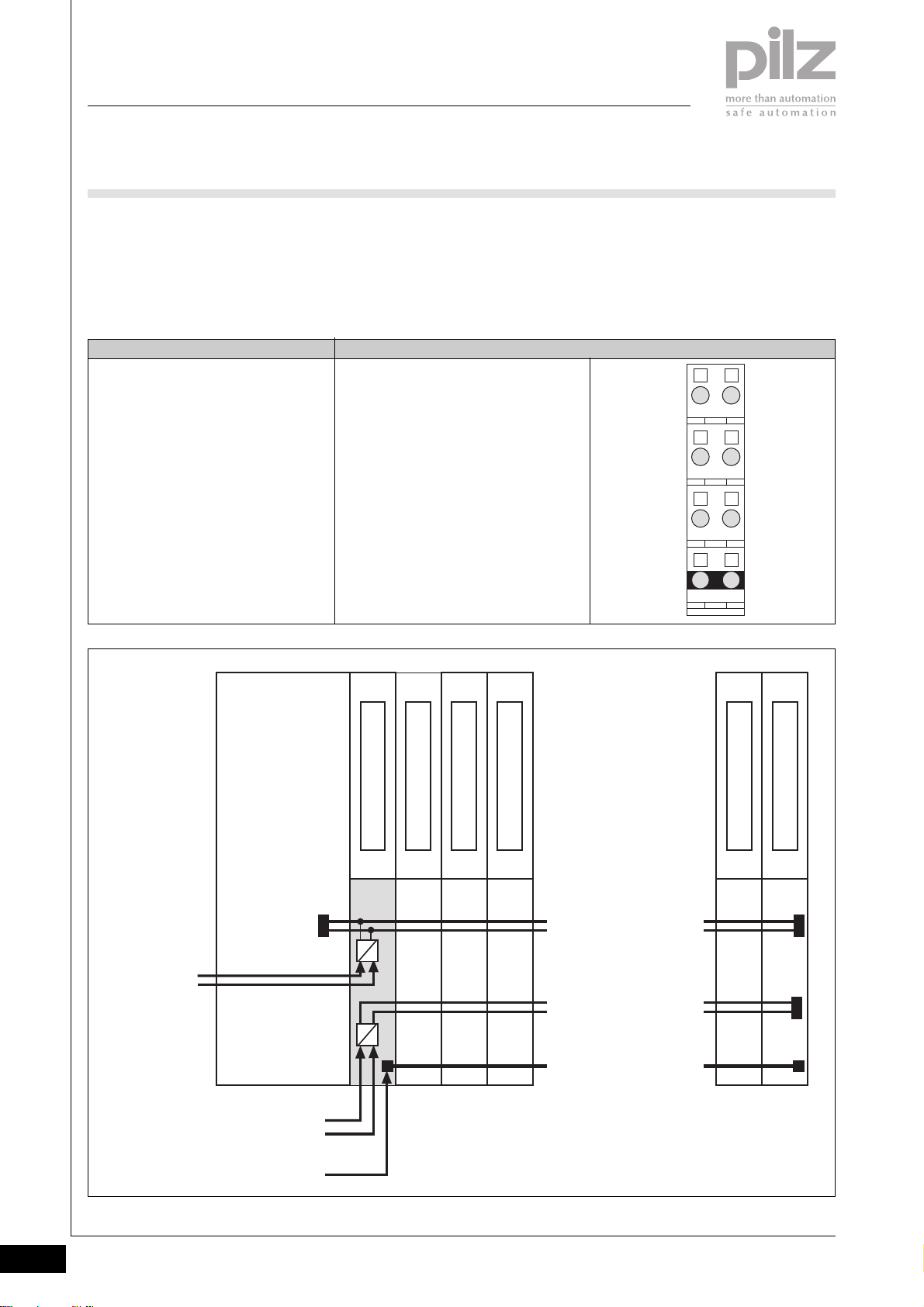
Base modules
- To provide the head module
and subsequent (right-hand)
` Terminal configuration
- General supply module
modules with the module
supply, periphery supply and
C-rail supply.
Base module Terminal configuration
Screw terminals:
PSSu BS 1/8S
Cage clamp terminals:
PSSu BS 1/8C
Note:
When the electronic module
PSSu E F PS is used with the listed base
modules, it may only be used as the first
module to the right of the head module!
11: +24 V Module supply
21: 0 V Module supply
12-22: 0 V Periphery supply
(12-22 linked internally)
13-23: +24 V Periphery supply
(13-23 linked internally)
14-24: Infeed for C-rail supply:
- PE
- Screening
- 0 V
- - 24 VDC ... + 24 VDC, 10 A
(14-24 linked internally)
2111
2212
2313
2414
Module Supply
(24 V DC)
Head Module
Periphery Supply
(24 V DC)
C-rail
Supply
I/O Module
PSSu E F PS
5 V DC
24 V DC
I/O Module
I/O Module
[ . . . ]
Module Bus
[ . . . ]
I/O Module
I/O Module
2.2-4
Pilz GmbH & Co. KG, Sichere Automation, Felix-Wankel-Straße 2, 73760 Ostfildern, Germany
Telephone +49 711 3409-0, Telefax +49 711 3409-133, E-Mail: [email protected]
Status 01/05
Page 46
PSSuniversal
Supply voltage
PSSu E F PS
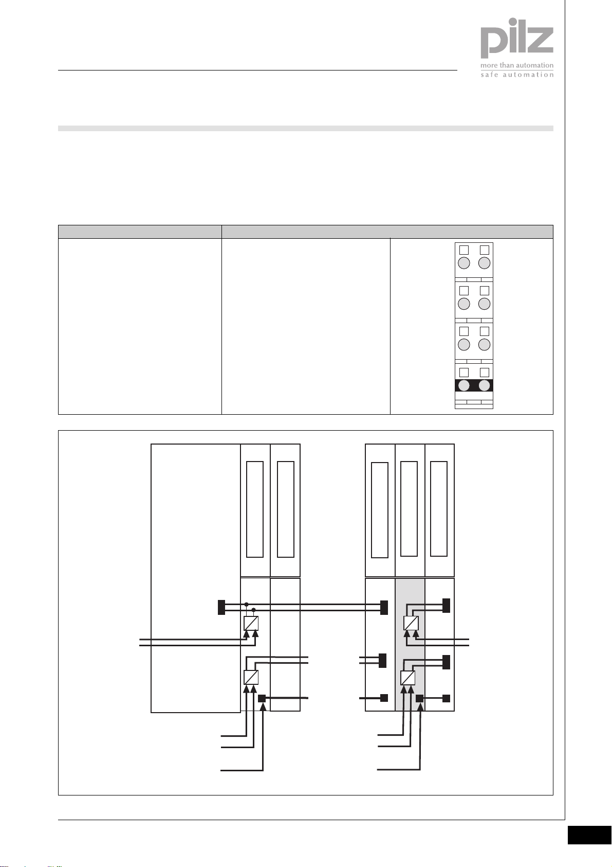
- Supply module to refresh the
module supply and periphery
supply
plus
supply module to form supply
groups
Base module Terminal configuration
Screw terminals:
PSSu BS-R 1/8S
Cage clamp terminals:
PSSu BS-R 1/8C
- To interrupt the incoming (lefthand) module supply, periphery
supply, C-rail
11: +24 V Module supply,
interrupted to the left
21: 0 V Module supply,
interrupted to the left
12-22: 0 V Periphery supply,
interrupted to the left
(12-22 linked internally)
13-23: +24 V Periphery supply,
interrupted to the left
(13-23 linked internally)
14-24: C-rail infeed, interrupted to the left
(14-24 linked internally)
- To provide subsequent (righthand) modules with the module
supply, periphery supply and
C-rail supply
2111
2
2212
2313
2414
Module Supply
(24 V DC)
Head Module
Periphery Supply
(24 V DC)
C-rail
Supply
I/O Module
PSSu E F PS
5 V DC
24 V DC
[ . . . ]
Module Bus
[ . . . ]
Periphery Supply
(24 V DC)
- Refresh
- Supply group
C-rail
Supply
I/O Module
PSSu E F PS
5 V DC
24 V DC
I/O Module
Module Supply
(24 V DC)
- Refresh
- Supply group
Pilz GmbH & Co. KG, Sichere Automation, Felix-Wankel-Straße 2, 73760 Ostfildern, Germany
Telephone +49 711 3409-0, Telefax +49 711 3409-133, E-Mail: [email protected]
Status 01/05
2.2-5
Page 47
PSSuniversal
Supply voltage
PSSu E F PS
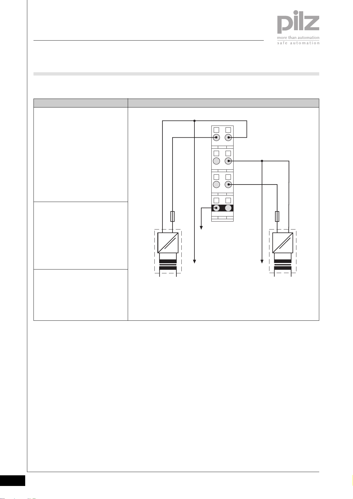
` Connection
ConnectionSupply type
General supply
with base module
- PSSu BS 1/8S or
- PSSu BS 1/8C
Note:
When the electronic module
PSSu E F PS is used with the listed base
modules, it may only be used as the first
module to the right of the head module!
Supply to refresh the
- module supply
- periphery supply
- C-rail supply
with base module
- PSSu BS-R 1/8S or
- PSSu BS-R 1/8C
Supply to form supply groups
with base module
- PSSu BS-R 1/8S or
- PSSu BS-R 1/8C
0 V DC
+24 V DC
Fuse Fuse
=
~
NL1
Module Supply
2111
0 V DC
2212
+24 V DC
2313
2414
C-rail Supply
Connect to the 0 V supply and
earth this at a single point
Periphery Supply
=
~
NL1
2.2-6
Pilz GmbH & Co. KG, Sichere Automation, Felix-Wankel-Straße 2, 73760 Ostfildern, Germany
Telephone +49 711 3409-0, Telefax +49 711 3409-133, E-Mail: [email protected]
Status 01/05
Page 48
PSSuniversal
Supply voltage
PSSu E F PS
Installation
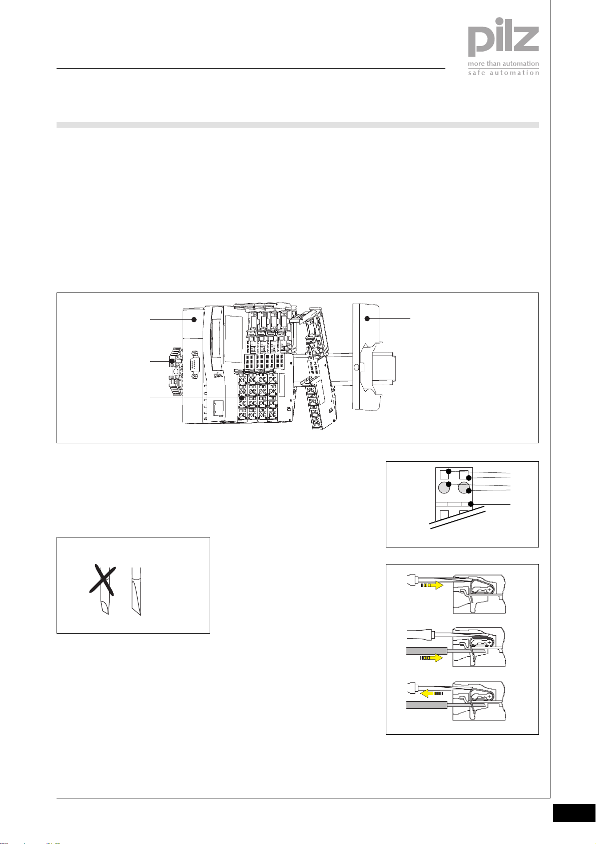
` Horizontal installation is
preferable!
Vertical installation is possible, but
involves restrictions in terms of
temperature and vibration
resistance.
` The head module must already be
installed.
` General supply:
- Attach the base module to the
DIN rail as the first module to
[1]
[2]
[3]
the right of the head module
and click into position on the
rail.
- Slide the base module to the
left until you hear it click into
the head module.
` Supply to refresh/form supply
groups
- Attach the base module to the
DIN rail to the right of the head
module [1] and click into
position on the rail [2].
- Slide the base module to the
left until you hear it click into
the last base module to be
installed.
` If necessary:
- Label the connection levels
with coloured markers. To do
this, push the markers into the
recess below the fixing holes.
` Secure the final module on the
mounting rail with the appropriate
fixing bracket [4].
2
[4]
Wiring the module
` Refer also to the sections entitled
“Wiring” and “Base modules”
` Use a flat blade screwdriver (DIN
5264-A)
DIN 5264-A
` Strip the wire back 8 mm
` Actuators may be connected
using unscreened cables.
` If necessary, label the connection
level with a colour marker [7]
` Base module with cage clamp
terminals:
- Insert the screwdriver [8] into
the square opening [5]
- Insert the stripped cable into
the round fixing hole [6], as far
as it will go [9]
- Pull out the screwdriver [10]
` Base module with screw terminals:
- Use a screwdriver to open the
screw on the screw terminal [5]
- Insert the stripped cable into
the round fixing hole [6], as far
as it will go
- Use a screwdriver to tighten up
the screw on the screw
terminal.
[5]
2111
[6]
[7]
[8]
[9]
[10]
Pilz GmbH & Co. KG, Sichere Automation, Felix-Wankel-Straße 2, 73760 Ostfildern, Germany
Telephone +49 711 3409-0, Telefax +49 711 3409-133, E-Mail: [email protected]
Status 01/05
2.2-7
Page 49
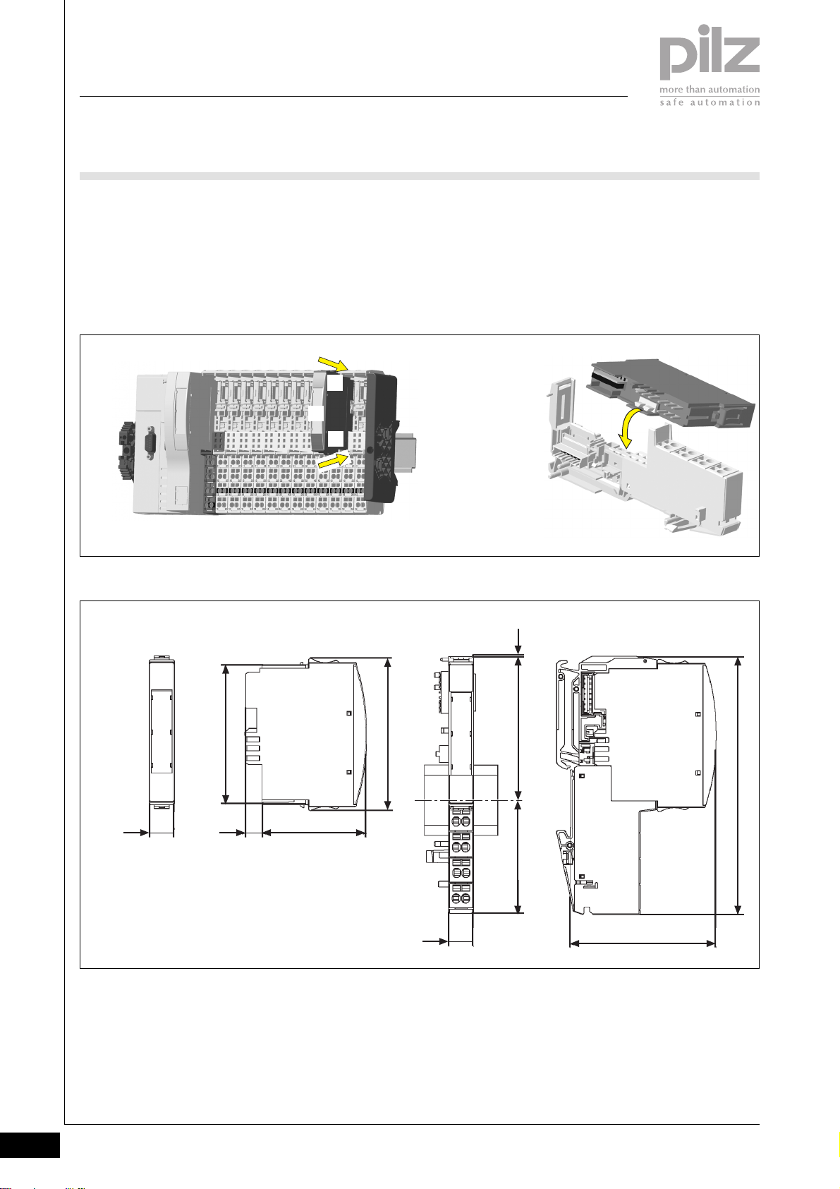
PSSuniversal
Supply voltage
PSSu E F PS
Inserting an electronic module
NOTICE
Ensure that a correct contact is
made. A correct contact can no
longer be guaranteed when modules
have been inserted and removed
more than 20 times.
Dimensions
` Electronic modules should
preferably be inserted on to base
modules that are already installed
and wired.
` The electronic module must
audibly lock into position [1].
` Label the electronic module using
the labelling strips [2]
[1]
[2]
[1]
INFORMATION
The first time an electronic module is
inserted on to a base module, the
base module is protected from
plugging errors via a mechanical
coding element [3].
[3]
67,7 mm
12,6 mm
Using this data sheet
This data sheet is only intended for
use during configuration.
NOTICE
Please refer to the operating
manual during commissioning and
operation.
0,8 mm
76 mm
52,1 mm8,1 mm
56,1 mm 71,8 mm
12,6 mm
72,6 mm
128,9 mm
2.2-8
Pilz GmbH & Co. KG, Sichere Automation, Felix-Wankel-Straße 2, 73760 Ostfildern, Germany
Telephone +49 711 3409-0, Telefax +49 711 3409-133, E-Mail: [email protected]
Status 01/05
Page 50
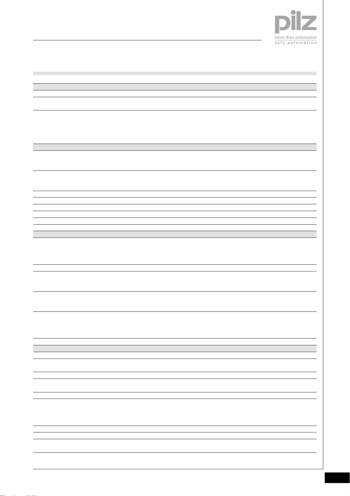
PSSuniversal
Supply voltage
PSSu E F PS
Technical details
Function
Application range
Electrical data
Supply voltage
Module supply
Periphery supply
Current consumption
Module supply
Periphery supply at < +50 °C
Load current, module supply
Load current, periphery supply at < +50 °C
C-rail supply
Total current on C-rail at 24 VDC, +25 °C/+60 °C
Module supply buffer in the case of a power supply failure
Periphery supply buffer in the case of a power supply failure
Mechanical data
Weight
Electronic module
Base module with cage clamp terminals
Base module with screw terminals
Mechanical coding
Plug in/out cycles
Electronic module
Base module
Max. cross section of external conductors with screw terminals
Flexible with crimp connectors
Flexible or rigid without crimp connectors
Max. cross section of external conductors with cage clamp
terminals
Flexible with crimp connectors
Flexible or rigid without crimp connectors
Torque setting with screw terminals
Environmental data
Protection type (EN 60529, 02/00)
Ambient temperature
(EN 60068-2-14, 11/99)
Storage temperature (EN 60068-2-1/-2, 07/94)
Climatic suitability
(EN 60068-2-78, 10/01)
Condensation
Vibration (EN 60068-2-6, 04/95)
Shock (EN 60068-2-27, 03/93)
Continuous shock (EN 60068-2-29, 04/93)
EMC
PSSu E F PS
Supply voltage for decentralised applications of the PSSu series
Failsafe applications conforming to
EN 954-1, 03/97,
DIN V 19 250, 05/94,
DIN VDE 0116, 09/97,
EN IEC 61508, 12/98
+18 VDC ... +30 VDC
+18 VDC ... +30 VDC
Max. 0.6 A
Max. 10 A
Max. 1.5 A
Max. 10 A
PE, screening, 0 V or 24 VDC ... +24 DC
Max. 10 A/ max. 8 A
< 4 ms
None
< 40 g
40 g
50 g
Yellow, B
Max. 20
Max. 20
0.5 ... 1.5 mm
0.5 ... 2.5 mm
0.5 ... 1.5 mm
0.5 ... 1.5 mm
0.8 Nm
IP20
0 ... +60 °C
-25 ... +70 °C
93 % r.h. at 40 °C
Not permitted
Frequency range: 10 ... 57 Hz
Amplitude: 0.075 mm
Frequency range: 57 ... 150 Hz
Acceleration: 1g
15g, 11 ms
10g, 16 ms
EN 61000-6-2, 08/02
EN 61000-6-4, 08/02
2
2
2
2
2
Pilz GmbH & Co. KG, Sichere Automation, Felix-Wankel-Straße 2, 73760 Ostfildern, Germany
Telephone +49 711 3409-0, Telefax +49 711 3409-133, E-Mail: [email protected]
Status 01/05
2.2-9
Page 51

PSSuniversal
Supply voltage
PSSu E F PS
Order reference
Description
PSSu E F PS
(Electronic module)
PSSu BS 1/8S
(Base module with screw terminals, to be used only as the first
module after the head module)
PSSu BS 1/8C
(Base module with cage clamp terminals, to be used only as the
first module after the head module)
PSSu BS-R 1/8S
(Base module with screw terminals, to be used to refresh the
voltage or to form supply groups)
PSSu BS-R 1/8C
(Base module with screw terminals, to be used to refresh the
voltage or to form supply groups)
Order reference for accessories
Description
Operating manual in German
Operating manual in English
Operating manual in French
Operating manual in Spanish
Operating manual in Italian
Operating manual in Dutch
Order no.
312 190
312 650
312 651
312 652
312 653
Order no.
In progress
In progress
In progress
In progress
In progress
In progress
2.2-10
Pilz GmbH & Co. KG, Sichere Automation, Felix-Wankel-Straße 2, 73760 Ostfildern, Germany
Telephone +49 711 3409-0, Telefax +49 711 3409-133, E-Mail: [email protected]
Status 01/05
Page 52
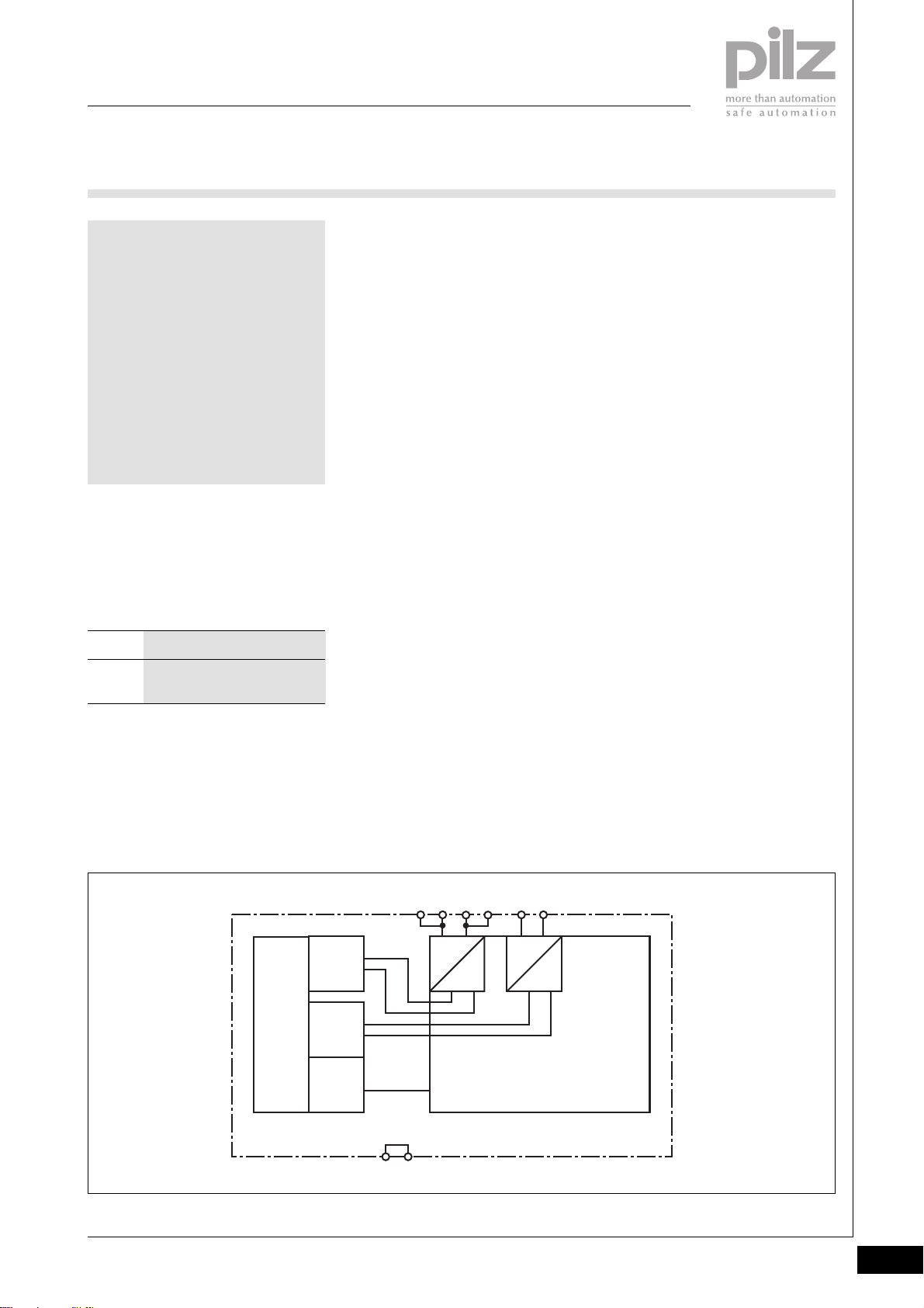
PSSuniversal
Supply voltage
PSSu E F PS1
PSSu E F PS1
not shown
Electronic module to provide the
system with the module supply,
periphery supply and C-rail supply.
Approvals
PSSu E F PS1
In progress
Module features
` Housing width: 25.2 mm
(2 x grid width)
` Supply for max. 20 modules
` Separate 24 VDC infeed for
module supply (5 VDC)
` Separate 24 VDC infeed for
periphery supply (24 VDC)
` Infeed for C-rail supply (if
required)
` LED indicators for:
- Module supply status
- Periphery supply status
- Module status
` Application depends on which
base module is used
` Details of the base modules that
can be used are available under
“Base modules” and “Order
reference”.
Module description
The module meets the requirements
of EN IEC 61508 and EN 954-1
Category 4. It provides the supply
for the module supply and periphery
supply within the system.
` Supply module to refresh the
module supply and periphery
supply
` Supply module to form supply
groups
Safety features
The module meets the following
safety requirements:
` When the module supply is
interrupted, the supply to a
maximum of 20 modules is
buffered for 20 ms.
` Protection against over-
temperature
` Module supply
- Integral voltage limitation
- Protection circuit for EMC
` Periphery supply
- Integral voltage monitoring
(exceeding upper/lower limit)
- Integral current monitoring
(exceeding upper/lower limit)
- Integral thermistor monitoring
` Diagnostic capabilities
2
Block diagram
Mo dule Bus
Depending on which base module is
used, the module may be used as a:
` General supply module (first
module after the head module)
13 23
Periphery
Supply
+ 24 V DC
Module
Supply
+ 5 V DC
Data
(FS)
cross connection
14 24
=
=
11 2112 22
=
=
Pilz GmbH & Co. KG, Sichere Automation, Felix-Wankel-Straße 2, 73760 Ostfildern, Germany
Telephone +49 711 3409-0, Telefax +49 711 3409-133, E-Mail: [email protected]
Status 01/05
2.2-11
Page 53

PSSuniversal
Supply voltage
PSSu E F PS1
Function description
` Using the module as the first
module after the head module
When the relevant base module is
used, the following supply can be
provided to the module bus:
- Module supply (+5 VDC) for
head module (left-hand side)
- Module supply (+5 VDC) for
subsequent modules (righthand side)
- Periphery supply (+24 VDC,
10 A) for subsequent modules
(right-hand side)
- C-rail supply for subsequent
modules (right-hand side)
` Using the module to refresh the
module supply and periphery
supply
When the relevant base module is
used, the connection to the
incoming (left-hand) module
supply, periphery supply and Crail is interrupted on the module
bus. The following supply is then
provided on the module bus for
subsequent (right-hand) modules:
- Module supply (+5 VDC) for
subsequent modules (righthand side)
- Periphery supply (+24 VDC,
10 A) for subsequent modules
(right-hand side)
- C-rail supply for subsequent
modules (right-hand side)
` Using the module to form supply
groups
When the relevant base module is
used, the connection to the
incoming (left-hand) module
supply, periphery supply and Crail is interrupted on the module
bus. The following supply is then
provided on the module bus for
subsequent (right-hand) modules:
- Module supply (+5 VDC) for
subsequent modules (righthand side)
- Periphery supply (+24 VDC,
10 A) for subsequent modules
(right-hand side)
- C-rail supply for subsequent
modules (right-hand side)
Each supply group requires its
own supply module.
` If galvanic isolation is required
between the module supply and
periphery supply, this is achieved
by feeding the voltages separately
(2 x 24 VDC). If this is not
required, one power supply is
sufficient for periphery supply and
module supply.
` It is not possible to switch off the
module supply if the lower voltage
limit is exceeded. However, there
will be a visual signal (LED “5 V”)
and a message will be sent to the
head module.
` It is not possible to switch off the
periphery supply if the upper/
lower limits of the monitored
parameters are exceeded.
However, there will be a visual
signal (LED “24 V”) and a
message will be sent to the head
module.
Overview of current consumption on
head modules and electronic
modules
PSSu H SB
PSSu H SB DP
PSSu E S 4DI
PSSu E S 4DO 0.5
PSSu E S 2DO 2
PSSu E F 4DI
PSSu E F 4DO 0.5
PSSu E F 2DO 2
PSSu E F 4DI OZ 2
PSSu E F 2DOR 8
PSSu E F BSW
PSSu E F PS-P
PSSu E PD
Max. current consumption ExplanationModule
≤ 300 mA
≤ 500 mA
≤ 25 mA
≤ 60 mA
≤ 50 mA
≤ 30 mA
≤ 75 mA
≤ 55 mA
≤ 35 mA
≤ 70 mA
≤ 220 mA
≤ 25 mA
0 mA
The load on the module supply is
determined by the current consumption
of the head module and electronic
modules that are used.
A PSSu E F PS supply module provides
a max. module supply of 1.5 A.
If a heavier load arises, an additional
supply module must be used to refresh
the module supply.
2.2-12
Pilz GmbH & Co. KG, Sichere Automation, Felix-Wankel-Straße 2, 73760 Ostfildern, Germany
Telephone +49 711 3409-0, Telefax +49 711 3409-133, E-Mail: [email protected]
Status 01/05
Page 54
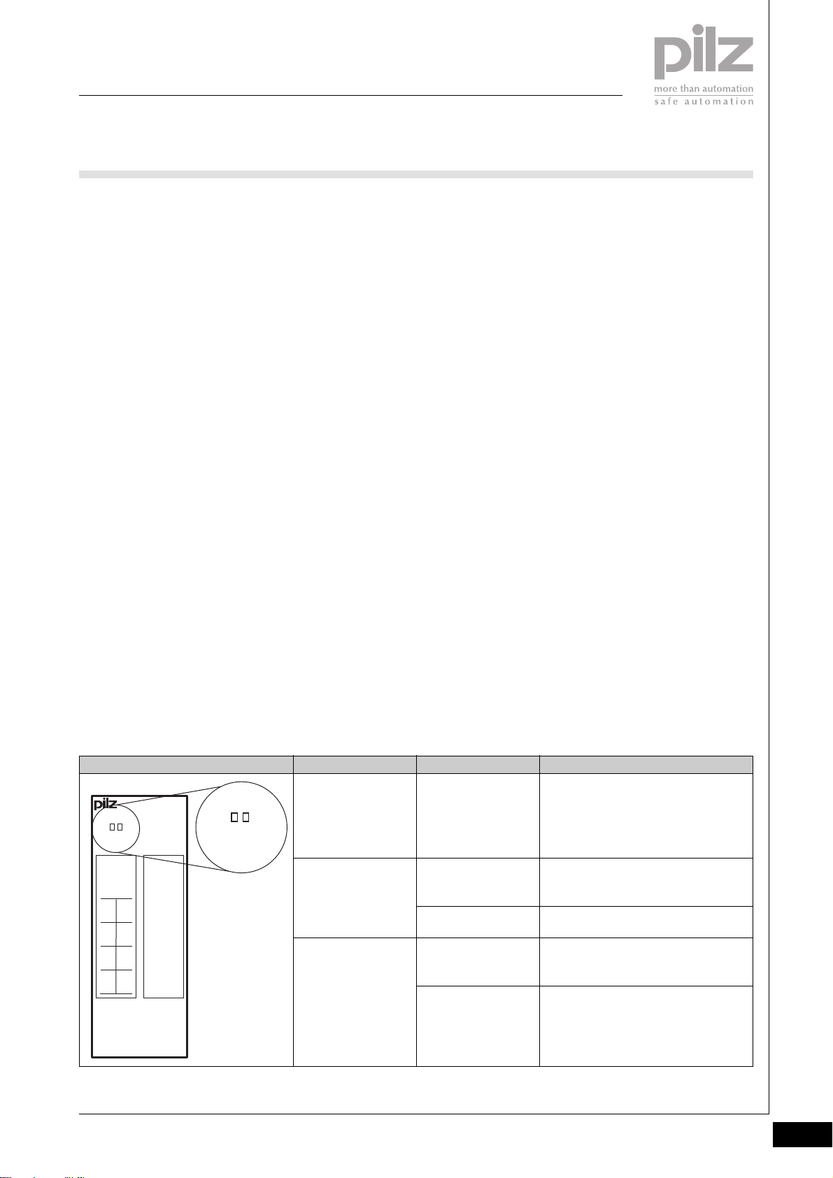
PSSuniversal
Supply voltage
PSSu E F PS1
Module diagnostics
` The module has various LEDs to
display the status of the
- Module supply (5 V)
- Periphery supply (24 V)
(see table below)
` Error reaction:
- Module supply error
If the lower voltage limit is
exceeded, a status message is
sent to the head module and
the “5 V” module LED (see
table)
- Periphery supply error
If the upper/lower limits of the
monitored parameters are
exceeded, a status message is
sent to the head module and
the “24 V” module LED (see
table)
- Module error
If a module error occurs (e.g.:
error at the inputs, error in
programming mode,
communication error), a status
message is sent to the head
module and the “Err” module
LED (see table)
- SafetyBUS p error
All the outputs in the affected
I/O-Group are shut down safely
and the I/O-Group switches to
a STOP condition. The error is
entered in the head module’s
error buffer.
Supply voltage
` The supply voltages for module
supply and periphery supply may
be in the range of +18 VDC ... +30
VDC. Safe operation cannot be
guaranteed outside this range.
` Safe electrical isolation must be
ensured for both the external 24 V
supplies. Failure to do so could
result in electric shock.
` Power supplies must conform to
EN 60950, 03/97, section 2.3, EN
60742, 9/95 or EN 50178, 10/97.
` To achieve the lowest possible
residual ripple (< ± 1.2 V), we
recommend that you install a
three-phase bridge rectifier or an
electronically regulated supply.
` If failsafe inputs are used, the
connection between “Ground”
(0 V periphery supply) and the
earth bar or earth fault monitor
must be in accordance with
relevant national regulations (e.g.
EN 60204-1, NFPA 79:17-7, NEC:
Article 250).
` On the module bus, the load
current of max. 10 A must not be
exceeded for the periphery
supply.
` A total current of max. 10 A must
not be exceeded on the C-rail.
Wiring
` Connect together the 0 V
connections on all the 24 V power
supplies and earth the 0 V supply
at a single point.
` The connection of the 0 V supply
to the central earth bar or earth
fault monitor must be in
accordance with relevant national
regulations (e.g. EN 60204-1,
NFPA 79:17-7, NEC: Article 250).
` Minimum range for cable cross
sections on connection terminals
in mm2, in accordance with EN
61131-2, 07/00:
- Power supply:
1.5 (AWG16) ... 2.5 (AWG12)
- Functional earth:
1.5 (AWG16) ... 2.5 (AWG12)
` Use copper wiring.
2
LED
Err
Err
Err
5 V 24 V
312191
11 21
0V24V
120V22
0V
13 23
24V 24V
14C24
C
PSSu E F
PS1
Pilz GmbH & Co. KG, Sichere Automation, Felix-Wankel-Straße 2, 73760 Ostfildern, Germany
Telephone +49 711 3409-0, Telefax +49 711 3409-133, E-Mail: [email protected]
5V 24V
24 V
5 V
LED statusElectronic module
Lights red
Off
Lights green
Off
Lights green
Key
Module error
(e.g.: error at the inputs, error in
programming mode, communication
error)
No supply voltage or
error in the supply voltage
for periphery supply
Supply voltage for periphery supply is
error-free
No supply voltage or
error in the supply voltage
for module supply
Supply voltage for module supply is
error-free
Status 01/05
2.2-13
Page 55
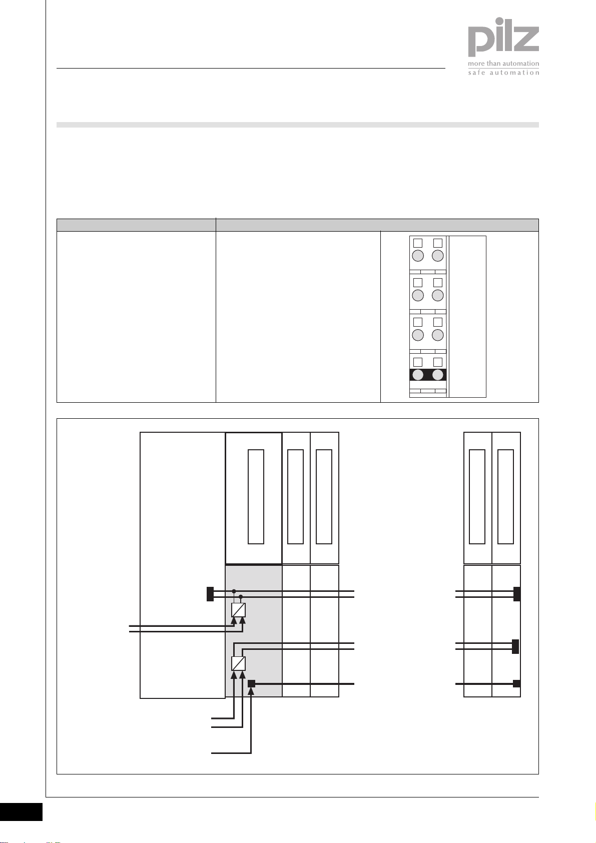
PSSuniversal
Supply voltage
PSSu E F PS1
Base modules
modules with the module
supply, periphery supply and
` Terminal configuration
C-rail supply
- General supply module
To provide the head module
and subsequent (right-hand)
Base module Terminal configuration
Screw terminals:
PSSu BS 2/8S
Cage clamp terminals:
PSSu BS 2/8C
Note:
When the electronic module
PSSu E F PS1 is used with the listed
base modules it may only be used as the
first module to the right of the head
module!
11: + 24 V Module supply
21: 0 V Module supply
12-22: 0 V Periphery supply
(12-22 linked internally)
13-23: + 24 V Periphery supply
(13-23 linked internally)
14-24: Infeed for C-rail supply:
- PE
- Screening
- 0 V
- - 24 VDC ... + 24 VDC, 10 A
(14-24 linked internally)
2111
2212
2313
2414
Module Supply
(24 V DC)
Head Module
Periphery Supply
(24 V DC)
C-rail
Supply
PSSu E F PS1
5 V DC
24 V DC
I/O Module
I/O Module
[ . . . ]
Module Bus
[ . . . ]
I/O Module
I/O Module
2.2-14
Pilz GmbH & Co. KG, Sichere Automation, Felix-Wankel-Straße 2, 73760 Ostfildern, Germany
Telephone +49 711 3409-0, Telefax +49 711 3409-133, E-Mail: [email protected]
Status 01/05
Page 56
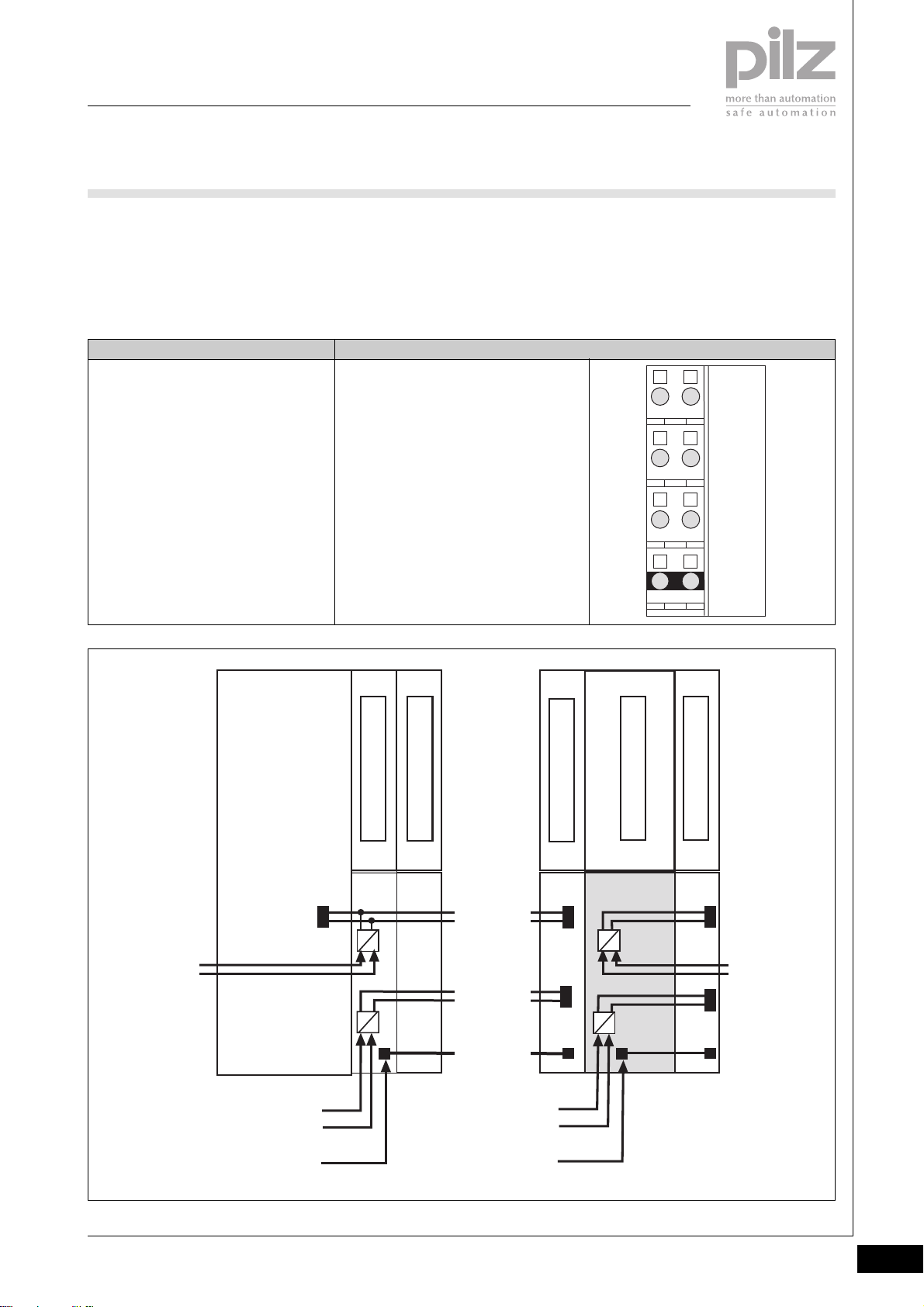
PSSuniversal
Supply voltage
PSSu E F PS1
- Supply module
- To refresh the module supply
and periphery supply
plus
supply module to form
supply groups
Base module Terminal configuration
Screw terminals:
PSSu BS-R 2/8S
Cage clamp terminals:
PSSu BS-R 2/8C
- To interrupt the incoming
(left-hand) module supply,
periphery supply, C-rail
11: + 24 V Module supply,
interrupted to the left
21: 0 V Module supply,
interrupted to the left
12-22: 0 V Periphery supply,
interrupted to the left
(12-22 linked internally)
13-23: + 24 V Periphery supply,
interrupted to the left
(13-23 linked internally)
14-24: C-rail infeed, interrupted to the left
(14-24 linked internally)
- To provide subsequent
(right-hand) modules with
the module supply, periphery
supply and C-rail supply
2111
2
2212
2313
2414
Module Supply
(24 V DC)
Head Module
Periphery Supply
(24 V DC)
C-rail
Supply
Power Supply
I/O Module
5 V DC
Module Bus
24 V DC
Periphery Supply
(24 V DC)
- Refresh
- Supply group
C-rail
Supply
[ . . . ]
[ . . . ]
I/O Module
5 V DC
24 V DC
PSSu E F PS1
I/O Module
Module Supply
(24 V DC)
- Refresh
- Supply group
Pilz GmbH & Co. KG, Sichere Automation, Felix-Wankel-Straße 2, 73760 Ostfildern, Germany
Telephone +49 711 3409-0, Telefax +49 711 3409-133, E-Mail: [email protected]
Status 01/05
2.2-15
Page 57
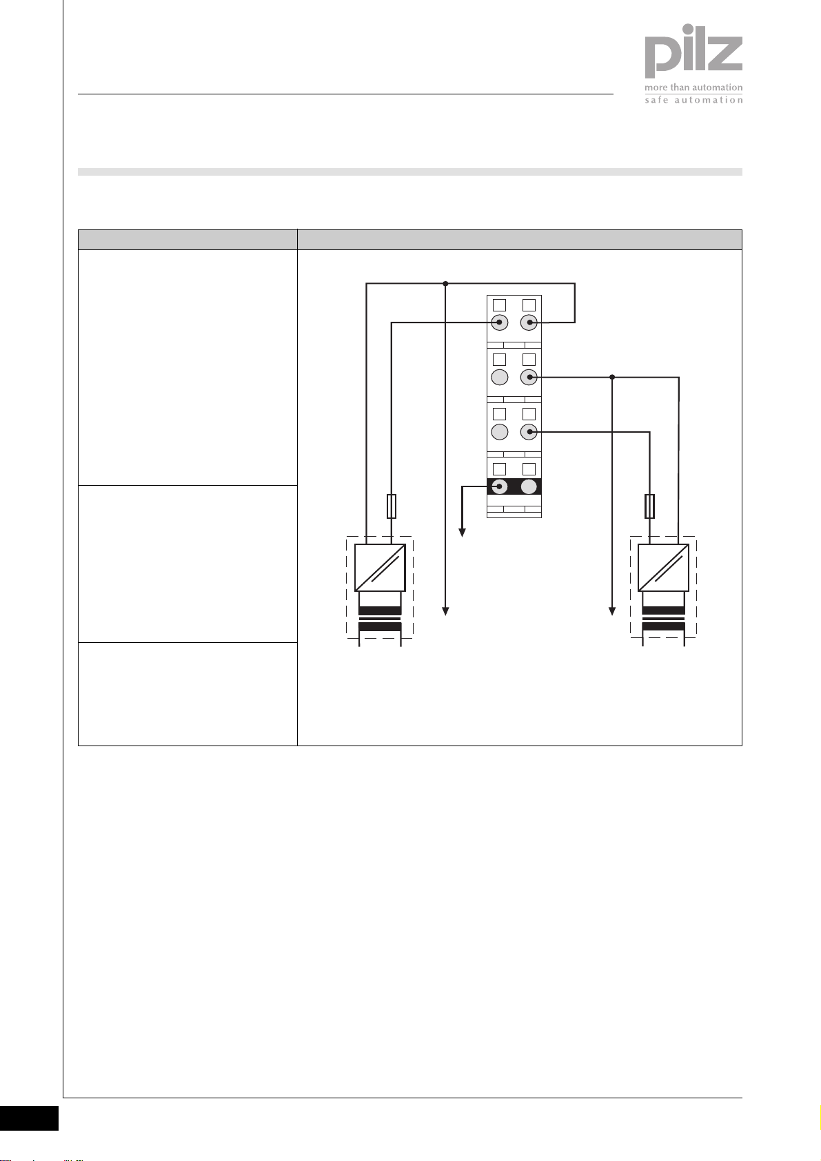
PSSuniversal
Supply voltage
PSSu E F PS1
` Connection
ConnectionSupply type
General supply
with base module
- PSSu BS 2/8S or
- PSSu BS 2/8C
Note:
When the electronic module
PSSu E F PS1 is used with the listed
base modules it may only be used as the
first module to the right of the head
module!
Supply to refresh the
- module supply
- periphery supply
- C-rail supply
with base module
- PSSu BS-R 2/8S or
- PSSu BS-R 2/8C
Supply to form supply groups
with base module
- PSSu BS-R 2/8S or
- PSSu BS-R 2/8C
0 V DC
+24 V DC
Fuse Fuse
=
~
NL1
Module Supply
2111
0 V DC
2212
+24 V DC
2313
2414
C-rail Supply
Connect to the 0 V supply and
earth this at a single point
=
~
NL1
Periphery Supply
2.2-16
Pilz GmbH & Co. KG, Sichere Automation, Felix-Wankel-Straße 2, 73760 Ostfildern, Germany
Telephone +49 711 3409-0, Telefax +49 711 3409-133, E-Mail: [email protected]
Status 01/05
Page 58
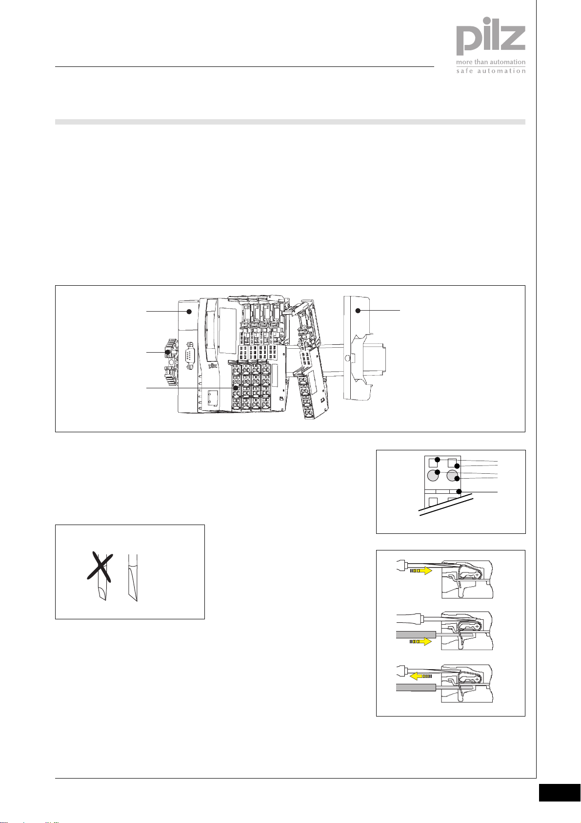
PSSuniversal
Supply voltage
PSSu E F PS1
Installation
` Horizontal installation is
preferable!
Vertical installation is possible, but
involves restrictions in terms of
temperature and vibration
resistance.
` The head module must already be
installed.
` General supply:
- Attach the base module to the
DIN rail as the first module to
[1]
[2]
[3]
the right of the head module
and click into position on the
rail.
- Slide the base module to the
left until you hear it click into
the head module.
` Supply to refresh/form supply
groups
- Attach the base module to the
DIN rail to the right of the head
module [1] and click into
position on the rail [2].
- Slide the base module to the
left until you hear it click into
the last base module to be
installed.
` If necessary:
- Label the connection levels
with coloured markers. To do
this, push the markers into the
recess below the fixing holes.
` Secure the final module on the
mounting rail with the appropriate
fixing bracket [4].
2
[4]
Wiring the module
` Refer also to the sections entitled
“Wiring” and “Base modules”!
` Use a flat blade screwdriver (DIN
5264-A)!
DIN 5264-A
` Strip the wire back 8 mm
` Actuators may be connected
using unscreened cables.
` If necessary, label the connection
level with a colour marker [7]
` Base module with cage clamp
terminals:
- Insert the screwdriver [8] into
the square opening [5]
- Insert the stripped cable into
the round fixing hole [6], as far
as it will go [9]
- Pull out the screwdriver [10]
` Base module with screw terminals:
- Use a screwdriver to open the
screw on the screw terminal [5]
- Insert the stripped cable into
the round fixing hole [6], as far
as it will go
- Use a screwdriver to tighten up
the screw on the screw
terminal.
[5]
2111
[6]
[7]
[8]
[9]
[10]
Pilz GmbH & Co. KG, Sichere Automation, Felix-Wankel-Straße 2, 73760 Ostfildern, Germany
Telephone +49 711 3409-0, Telefax +49 711 3409-133, E-Mail: [email protected]
Status 01/05
2.2-17
Page 59
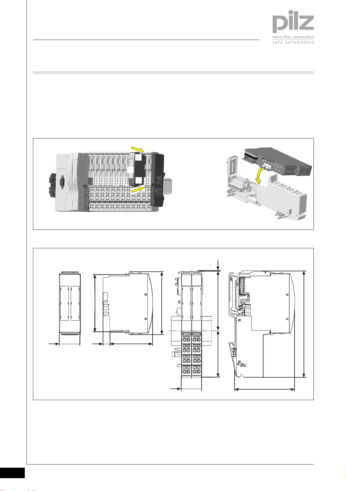
PSSuniversal
Supply voltage
PSSu E F PS1
Inserting an electronic module
NOTICE
Ensure that a correct contact is
made. A correct contact can no
longer be guaranteed when modules
have been inserted and removed
more than 20 times.
Dimensions
` Electronic modules should
preferably be inserted on to base
modules that are already installed
and wired.
` The electronic module must
audibly lock into position [1].
` Label the electronic module using
the labelling strips [2]
[1]
[2]
[1]
INFORMATION
The first time an electronic module is
inserted on to a base module, the
base module is protected from
plugging errors via a mechanical
coding element [3].
[3]
67,7 mm
25,2 mm
Using this data sheet
This data sheet is only intended for
use during configuration.
NOTICE
Please refer to the operating
manual during commissioning and
operation.
0,8 mm
76 mm
52,1 mm8,1 mm
56,1 mm 71,8 mm
25,2 mm
72,7 mm
128,9 mm
2.2-18
Pilz GmbH & Co. KG, Sichere Automation, Felix-Wankel-Straße 2, 73760 Ostfildern, Germany
Telephone +49 711 3409-0, Telefax +49 711 3409-133, E-Mail: [email protected]
Status 01/05
Page 60
PSSuniversal
Supply voltage
PSSu E F PS1
Technical details
Function
Application range
Electrical data
Supply voltage
Module supply
Periphery supply
Current consumption
Module supply
Periphery supply at < +50 °C
Load current, module supply
Load current, periphery supply at < +50 °C
C-rail infeed
Total current on C-rail at +24 VDC, +25 °C/+60 °C
Module supply buffer in the case of a power supply failure
Periphery supply buffer in the case of a power supply failure
Mechanical data
Weight
Electronic module
Base module with cage clamp terminals
Base module with screw terminals
Mechanical coding
Plug in/out cycles
Electronic module
Base module
Max. cross section of external conductors with screw terminals
Flexible with crimp connectors
Flexible or rigid without crimp connectors
Max. cross section of external conductors with cage clamp
terminals
Flexible with crimp connectors
Flexible or rigid without crimp connectors
Torque setting with screw terminals
Environmental data
Protection type (EN 60529, 02/00)
Ambient temperature
(EN 60068-2-14, 11/99)
Storage temperature (EN 60068-2-1/-2, 07/94)
Climatic suitability
(EN 60068-2-78, 10/01)
Condensation
Vibration (EN 60068-2-6, 04/95)
Shock (EN 60068-2-27, 03/93)
Continuous shock (EN 60068-2-29, 04/93)
EMC
PSSu E F PS1
Supply voltage for decentralised applications of the PSSu series
Failsafe applications conforming to
EN 954-1, 03/97,
DIN V 19 250, 05/94,
DIN VDE 0116, 09/97,
EN IEC 61508, 12/98
+18 VDC ... +30 VDC
+18 VDC ... +30 VDC
Max. 0.7 A
Max. 10 A
Max. 2 A
Max. 10 A
PE, screening, 0 V or 24 VDC ... +24 DC
Max. 10 A/ max. 8 A
> 20 ms
None
< 40 g
40 g
50 g
Yellow, C
Max. 20
Max. 20
0.5 ... 1.5 mm
0.5 ... 2.5 mm
0.5 ... 1.5 mm
0.5 ... 1.5 mm
0.8 Nm
IP20
0 ... +60 °C
-25 ... +70 °C
93 % r.h. at 40 °C
Not permitted
Frequency range: 10 ... 57 Hz
Amplitude: 0.075 mm
Frequency range: 57 ... 150 Hz
Acceleration: 1g
15g, 11 ms
10g, 16 ms
EN 61000-6-2, 08/02
EN 61000-6-4, 08/02
2
2
2
2
2
Pilz GmbH & Co. KG, Sichere Automation, Felix-Wankel-Straße 2, 73760 Ostfildern, Germany
Telephone +49 711 3409-0, Telefax +49 711 3409-133, E-Mail: [email protected]
Status 01/05
2.2-19
Page 61
PSSuniversal
Supply voltage
PSSu E F PS1
Order reference
Description
PSSu E F PS1
(Electronic module)
PSSu BS 2/8S
(Base module with screw terminals, to be used only as the first
module after the head module)
PSSu BS 2/8C
(Base module with cage clamp terminals, to be used only as the
first module after the head module)
PSSu BS-R 2/8S
(Base module with screw terminals, to be used to refresh the
voltage or form supply groups)
PSSu BS-R 2/8C
(Base module with cage clamp terminals, to be used to refresh
the voltage or form supply groups)
Order reference for accessories
Description
Operating manual in German
Operating manual in English
Operating manual in French
Operating manual in Spanish
Operating manual in Italian
Operating manual in Dutch
Order no.
312 191
312 656
312 657
312 654
312 655
Order no.
In progress
In progress
In progress
In progress
In progress
In progress
2.2-20
Pilz GmbH & Co. KG, Sichere Automation, Felix-Wankel-Straße 2, 73760 Ostfildern, Germany
Telephone +49 711 3409-0, Telefax +49 711 3409-133, E-Mail: [email protected]
Status 01/05
Page 62
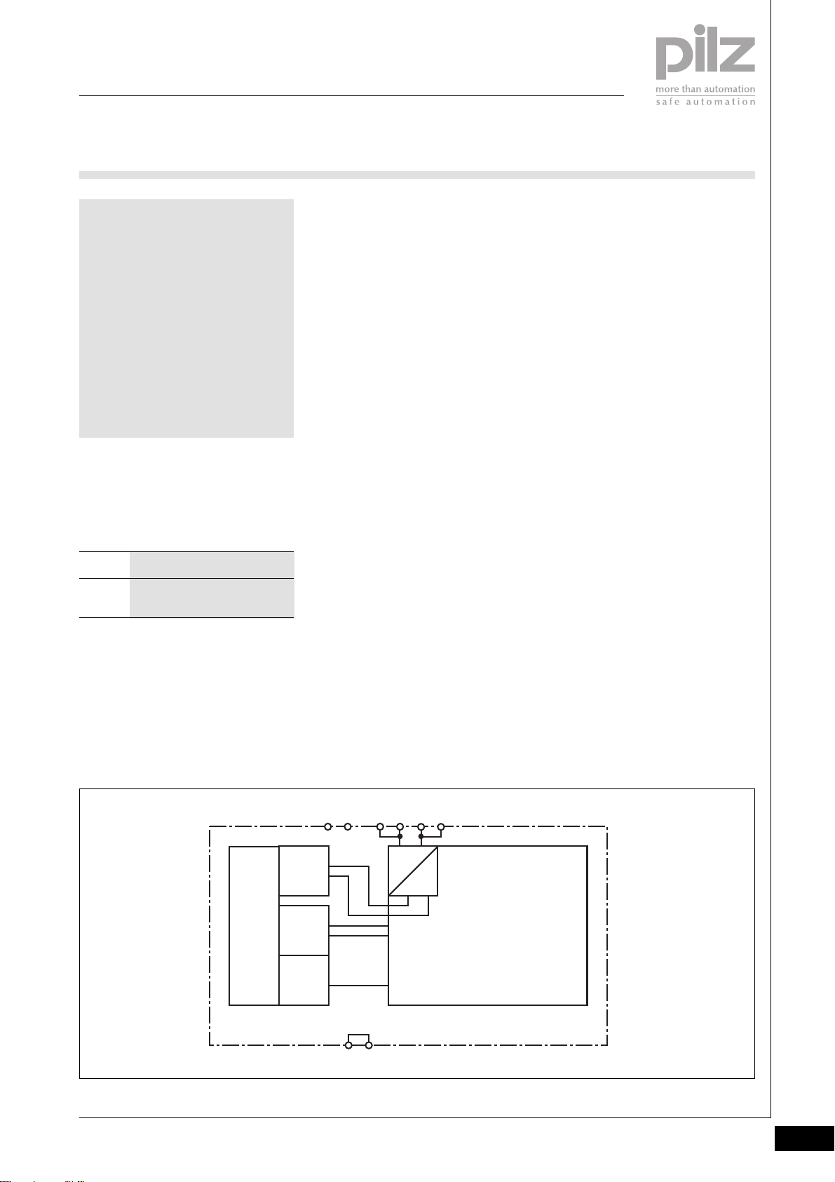
PSSuniversal
Supply voltage
PSSu E F PS-P
PSSu E F PS-P
not shown
Electronic module to provide the
system with the periphery supply and
C-rail supply.
Approvals
PSSu E F PS-P
In progress
Module features
` Housing width: 12.6 mm
(1 x grid width)
` Provides the module with the
module supply (5 VDC) via the
module bus
` 24 VDC infeed for periphery
supply (24 VDC)
` Infeed for C-rail supply (if
required)
` LED indicators for:
- Module error
` Details of the base modules that
can be used are available under
“Base modules” and “Order
reference”.
Module description
The module meets the requirements
of EN IEC 61508 and EN 954-1
Category 4. It provides the periphery
supply within the system.
Depending on which base module is
used, the module may be used as a:
` Supply module to refresh the
periphery supply
Safety features
The module meets the following
safety requirements:
` Protection against over-
temperature
` Periphery supply
- Integral voltage monitoring
(exceeding upper/lower limit)
- Integral current monitoring
(exceeding upper/lower limit)
- Integral thermistor monitoring
` Diagnostic capabilities
2
Block diagram
11 21 12 22
Periphery
Supply
+ 24 V DC
Module
Supply
+ 5 V DC
Mo dule Bus
Data
(FS)
cross connection
14 24
Pilz GmbH & Co. KG, Sichere Automation, Felix-Wankel-Straße 2, 73760 Ostfildern, Germany
Telephone +49 711 3409-0, Telefax +49 711 3409-133, E-Mail: [email protected]
13 23
=
=
Status 01/05
2.2-21
Page 63

PSSuniversal
Supply voltage
PSSu E F PS-P
Function description
` Module supply (5 VDC)
The electronics are supplied via
the module bus.
` Using the module to refresh the
periphery supply
The connection to the incoming
(left-hand) periphery supply and
C-rail is interrupted on the module
bus through the base module. The
following supply is then provided
on the module bus for subsequent
(right-hand) modules:
- Periphery supply (24 VDC,
10 A) for subsequent modules
(right-hand side)
- C-rail supply for subsequent
modules (right-hand side)
` If galvanic isolation is required
between the module supply and
periphery supply, this is achieved
by feeding the voltages separately
(2 x 24 VDC). If this is not
required, one power supply is
sufficient for periphery supply and
module supply.
` It is not possible to switch off the
periphery supply if the upper/
lower limits of the monitored
parameters are exceeded.
However, there will be a visual
signal (LED “24 V”) and a
message will be sent to the head
module.
2.2-22
Pilz GmbH & Co. KG, Sichere Automation, Felix-Wankel-Straße 2, 73760 Ostfildern, Germany
Telephone +49 711 3409-0, Telefax +49 711 3409-133, E-Mail: [email protected]
Status 01/05
Page 64

PSSuniversal
Supply voltage
PSSu E F PS-P
Module diagnostics
` The module has various LEDs to
display
-
Periphery supply status (“24 V”)
- Module error (“Err”)
(see table below)
` Error reaction:
- Periphery supply error
If the upper/lower limits of the
monitored parameters are
exceeded, a status message is
sent to the head module and
the “24 V” module LED (see
table)
- Module error
If a module error occurs (e.g.:
error at the inputs, error in
programming mode,
communication error), a status
message is sent to the head
module and the “Err” module
LED (see table)
- SafetyBUS p error
All the outputs in the affected
I/O-Group are shut down safely
and the I/O-Group switches to
a STOP condition. The error is
entered in the head module’s
error buffer.
Supply voltage
` The supply voltage for periphery
supply may be in the range of +18
VDC ... +30 VDC. Safe operation
cannot be guaranteed outside this
range.
` Safe electrical isolation must be
ensured for the external 24 V
supply. Failure to do so could
result in electric shock.
` The power supply must conform
to EN 60950, 03/97, section 2.3,
EN 60742, 9/95 or EN 50178,
10/97.
` To achieve the lowest possible
residual ripple (< ± 1.2 V), we
recommend that you install a
three-phase bridge rectifier or an
electronically regulated supply.
` If failsafe inputs are used, the
connection between “Ground”
(0 V periphery supply) and the
earth bar or earth fault monitor
must be in accordance with
relevant national regulations (e.g.
EN 60204-1, NFPA 79:17-7, NEC:
Article 250, for example).
` On the module bus, the load
current of max. 10 A must not be
exceeded for the periphery
supply.
` A total current of max. 10 A must
not be exceeded on the C-rail.
Wiring
` Connect together the 0 V
connections on all the 24 V power
supplies and earth the 0 V supply
at a single point.
` The connection of the 0 V supply
to the central earth bar or earth
fault monitor must be in accordance with relevant national
regulations (e.g. EN 60204-1,
NFPA 79:17-7, NEC: Article 250).
` Minimum range for cable cross
sections on connection terminals
in mm2, in accordance with EN
61131-2, 07/00:
- Power supply:
1.5 (AWG16) ... 2.5 (AWG12)
- Functional earth:
1.5 (AWG16) ... 2.5 (AWG12)
` Use copper wiring.
2
LED
Err
Err
24V
312185
11 21
120V22
0V
13 23
24V 24V
14C24
C
PSSu E F
PS-P
Pilz GmbH & Co. KG, Sichere Automation, Felix-Wankel-Straße 2, 73760 Ostfildern, Germany
Telephone +49 711 3409-0, Telefax +49 711 3409-133, E-Mail: [email protected]
Err
24V
24 V
LED statusElectronic module
Lights red
Off
Lights green
Key
Module error
(e.g.: error at the inputs, error in
programming mode, communication
error)
No supply voltage or
error in the supply voltage
for periphery supply
Supply voltage for periphery supply is
error-free
Status 01/05
2.2-23
Page 65
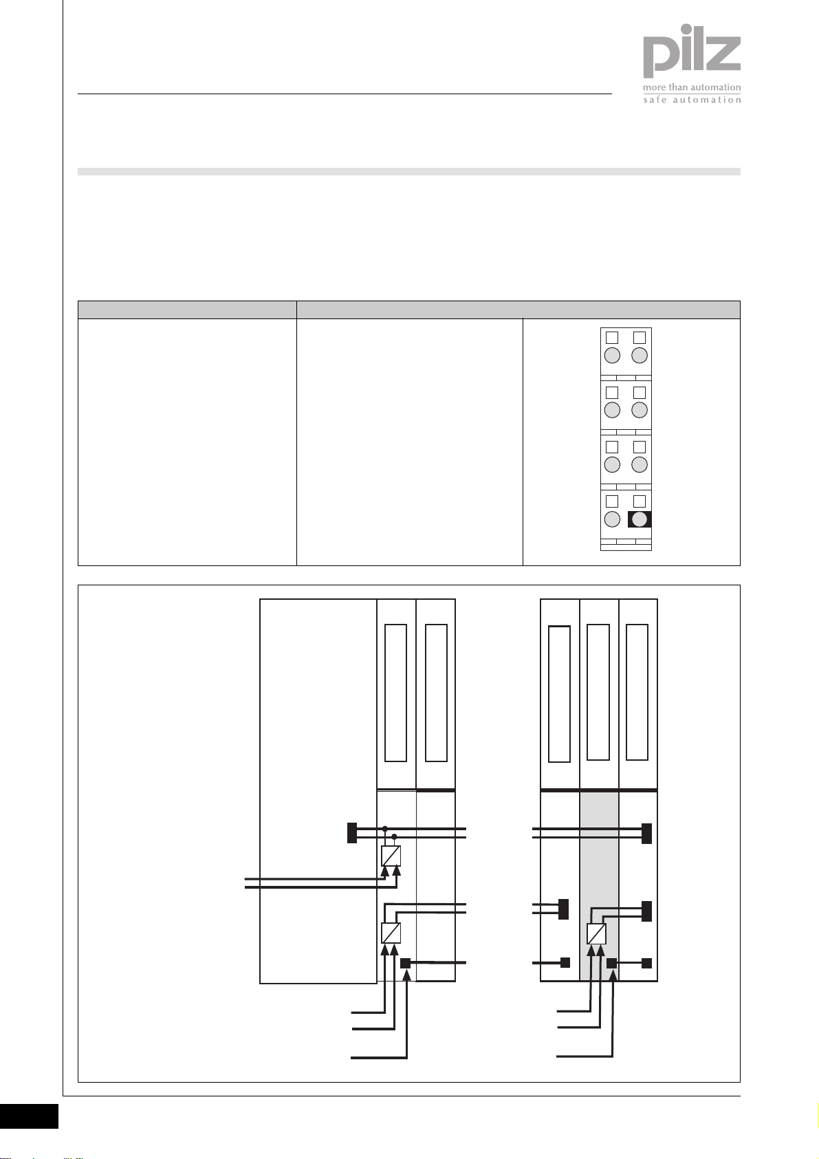
PSSuniversal
Supply voltage
PSSu E F PS-P
Base modules
` Terminal configuration
Supply module
- To refresh the periphery supply
Base module Terminal configuration
Screw terminals:
PSSu BS 1/8S
Cage clamp terminals:
PSSu BS 1/8C
- To interrupt the incoming (lefthand) periphery supply and Crail
11: Not assigned
21: Not assigned
12-22: 0 V Periphery supply,
interrupted to the left
(12-22 linked internally)
13-23: +24 V Periphery supply,
interrupted to the left
(13-23 linked internally)
14-24: Infeed for C-rail supply, interrupted
to the left:
- PE
- Screening
- 0 V
- - 24 VDC ... + 24 VDC, 10 A
(14-24 linked internally)
- To provide the subsequent
(right-hand) modules with the
periphery supply and C-rail
supply
2111
2212
2313
2414
Module Supply
(24 V DC)
Head Module
Periphery Supply
(24 V DC)
C-rail
Supply
I/O Module
Power Supply
5 V DC
24 V DC
Periphery Supply
(24 V DC)
- Refresh
- Supply group
C-rail
Supply
[ . . . ]
Module Bus
[ . . . ]
I/O Module
PSSu E F PS-P
24 V DC
I/O Module
2.2-24
Pilz GmbH & Co. KG, Sichere Automation, Felix-Wankel-Straße 2, 73760 Ostfildern, Germany
Telephone +49 711 3409-0, Telefax +49 711 3409-133, E-Mail: [email protected]
Status 01/05
Page 66
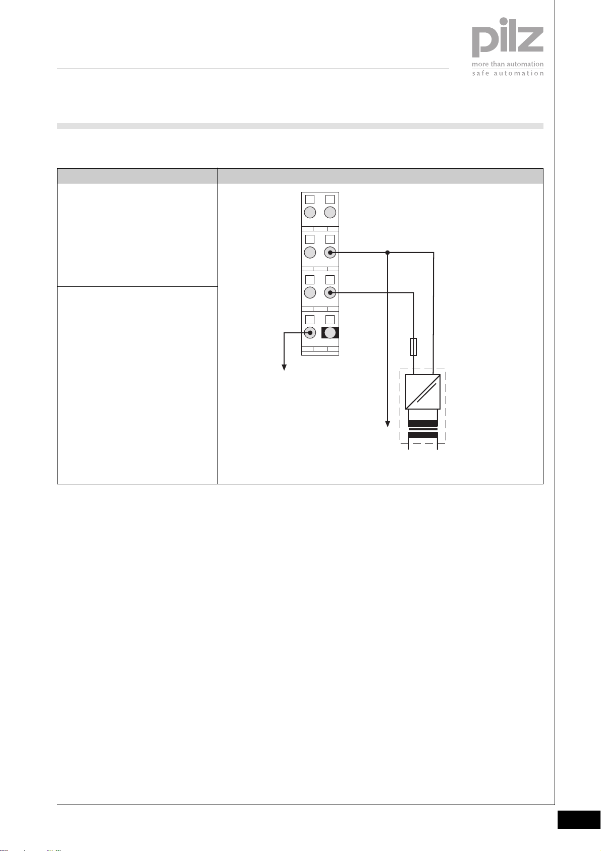
PSSuniversal
Supply voltage
PSSu E F PS-P
` Connection
Supply to refresh the
- Periphery supply
- C-rail supply
with base module
- PSSu BS 1/8S or
- PSSu BS 1/8C
Supply to form supply groups
with base module
- PSSu BS 1/8S or
- PSSu BS 1/8C
ConnectionSupply type
2111
0 V DC
2212
+24 V DC
2313
2414
Fuse
2
C-rail
Supply
Connect to the 0 V supply and
earth this at a single point
Periphery Supply
=
~
NL1
Pilz GmbH & Co. KG, Sichere Automation, Felix-Wankel-Straße 2, 73760 Ostfildern, Germany
Telephone +49 711 3409-0, Telefax +49 711 3409-133, E-Mail: [email protected]
Status 01/05
2.2-25
Page 67
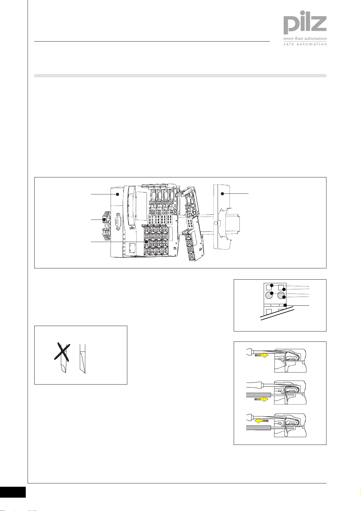
PSSuniversal
Supply voltage
PSSu E F PS-P
Installation
` Horizontal installation is
preferable!
Vertical installation is possible, but
involves restrictions in terms of
temperature and vibration
resistance.
` The head module must already be
installed.
` Attach the base module to the DIN
[1]
[2]
[3]
rail to the right of the head module
[1] and click into position on the
rail [2].
` Slide the base module to the left
until you hear it click into the last
base module to be installed.
` If necessary:
- Label the connection levels
with coloured markers. To do
this, push the markers into the
recess below the fixing holes.
` Secure the final module on the
mounting rail with the appropriate
fixing bracket [4].
[4]
Wiring the module
` Refer also to the sections entitled
“Wiring” and “Base modules”
` Use a flat blade screwdriver (DIN
5264-A)
DIN 5264-A
` Strip the wire back 8 mm
` Actuators may be connected
using unscreened cables.
` If necessary, label the connection
level with a colour marker [7]
` Base module with cage clamp
terminals:
- Insert the screwdriver [8] into
the square opening [5]
- Insert the stripped cable into
the round fixing hole [6], as far
as it will go [9]
- Pull out the screwdriver [10]
` Base module with screw terminals:
- Use a screwdriver to open the
screw on the screw terminal [5]
- Insert the stripped cable into
the round fixing hole [6], as far
as it will go
- Use a screwdriver to tighten up
the screw on the screw
terminal.
[5]
2111
[6]
[7]
[8]
[9]
[10]
2.2-26
Pilz GmbH & Co. KG, Sichere Automation, Felix-Wankel-Straße 2, 73760 Ostfildern, Germany
Telephone +49 711 3409-0, Telefax +49 711 3409-133, E-Mail: [email protected]
Status 01/05
Page 68
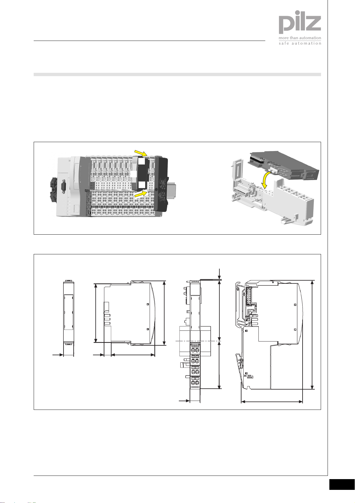
PSSuniversal
Supply voltage
PSSu E F PS-P
Inserting an electronic module
NOTICE
Ensure that a correct contact is
made. A correct contact can no
longer be guaranteed when modules
have been inserted and removed
more than 20 times.
Dimensions
` Electronic modules should
preferably be inserted on to base
modules that are already installed
and wired.
` The electronic module must
audibly lock into position [1].
` Label the electronic module using
the labelling strips [2]
[1]
[2]
[1]
INFORMATION
The first time an electronic module is
inserted on to a base module, the
base module is protected from
plugging errors via a mechanical
coding element [3].
2
[3]
67,7 mm
12,6 mm
Using this data sheet
This data sheet is only intended for
use during configuration.
NOTICE
Please refer to the operating
manual during commissioning and
operation.
0,8 mm
76 mm
52,1 mm8,1 mm
56,1 mm 71,8 mm
12,6 mm
72,6 mm
128,9 mm
Pilz GmbH & Co. KG, Sichere Automation, Felix-Wankel-Straße 2, 73760 Ostfildern, Germany
Telephone +49 711 3409-0, Telefax +49 711 3409-133, E-Mail: [email protected]
Status 01/05
2.2-27
Page 69
PSSuniversal
Supply voltage
PSSu E F PS-P
Technical details
Function
Application range
Electrical data
Supply voltage
Periphery supply
Current consumption
Module supply
Periphery supply at < +50 °C
Load current, periphery supply at < +50 °C
C-rail supply
Total current on C-rail at +24 VDC, +25 °C/+60 °C
Module supply buffer in the case of a power supply failure
Periphery supply buffer in the case of a power supply failure
Mechanical data
Weight
Electronic module
Base module with cage clamp terminals
Base module with screw terminals
Mechanical coding
Plug in/out cycles
Electronic module
Base module
Max. cross section of external conductors with screw terminals
Flexible with crimp connectors
Flexible or rigid without crimp connectors
Max. cross section of external conductors with cage clamp
terminals
Flexible with crimp connectors
Flexible or rigid without crimp connectors
Torque setting with screw terminals
Environmental data
Protection type (EN 60529, 02/00)
Ambient temperature
(EN 60068-2-14, 11/99)
Storage temperature (EN 60068-2-1/-2, 07/94)
Climatic suitability
(EN 60068-2-78, 10/01)
Condensation
Vibration (EN 60068-2-6, 04/95)
Shock (EN 60068-2-27, 03/93)
Continuous shock (EN 60068-2-29, 04/93)
EMC
PSSu E F PS-P
Supply voltage for decentralised applications of the PSSu series
Failsafe applications conforming to
EN 954-1, 03/97,
DIN V 19 250, 05/94,
DIN VDE 0116, 09/97,
EN IEC 61508, 12/98
+18 VDC ... +30 VDC
< 30 mA
Max. 10 A
Max. 10 A
PE, screening, 0 V or 24 VDC ... +24 DC
Max. 10 A/ max. 8 A
None
None
< 40 g
40 g
50 g
Yellow, A
Max. 20
Max. 20
0.5 ... 1.5 mm
0.5 ... 2.5 mm
0.5 ... 1.5 mm
0.5 ... 1.5 mm
0.8 Nm
IP20
0 ... +60 °C
-25 ... +70 °C
93 % r.h. at 40 °C
Not permitted
Frequency range: 10 ... 57 Hz
Amplitude: 0.075 mm
Frequency range: 57 ... 150 Hz
Acceleration: 1g
15g, 11 ms
10g, 16 ms
EN 61000-6-2, 08/02
EN 61000-6-4, 08/02
2
2
2
2
2.2-28
Pilz GmbH & Co. KG, Sichere Automation, Felix-Wankel-Straße 2, 73760 Ostfildern, Germany
Telephone +49 711 3409-0, Telefax +49 711 3409-133, E-Mail: [email protected]
Status 01/05
Page 70
PSSuniversal
Supply voltage
PSSu E F PS-P
Order reference
Description
PSSu E F PS-P
(Electronic module)
PSSu BS 1/8S
(Base module with screw terminals)
PSSu BS 1/8C
(Base module with cage clamp terminals)
Order reference for accessories
Description
Operating manual in German
Operating manual in English
Operating manual in French
Operating manual in Spanish
Operating manual in Italian
Operating manual in Dutch
Order no.
312 185
312 650
312 651
2
Order no.
In progress
In progress
In progress
In progress
In progress
In progress
Pilz GmbH & Co. KG, Sichere Automation, Felix-Wankel-Straße 2, 73760 Ostfildern, Germany
Telephone +49 711 3409-0, Telefax +49 711 3409-133, E-Mail: [email protected]
Status 01/05
2.2-29
Page 71

PSSuniversal
Supply voltage
PSSu E F PS-P
Notes
2.2-30
Pilz GmbH & Co. KG, Sichere Automation, Felix-Wankel-Straße 2, 73760 Ostfildern, Germany
Telephone +49 711 3409-0, Telefax +49 711 3409-133, E-Mail: [email protected]
Status 01/05
Page 72
PSSuniversal
Supply voltage
PSSu E F BSW
PSSu E F BSW
not shown
Electronic module for switching the
periphery supply on non-safetyrelated input/output modules
arranged in blocks. For safetyrelated functions
Approvals
PSSu E F BSW
In progress
Module features
` Housing width: 25.2 mm
(2 x grid width)
` 24 VDC infeed for periphery
supply (24 VDC)
` Infeed to C-rail supply (if required)
` Failsafe switching on/off of the
periphery supply (+24 VDC, 0 V)
(block switching)
` LED indicators for:
Module error
` Details of the base modules that
can be used are available under
“Base modules” and “Order
reference”
Module description
The module meets the requirements
of EN IEC 61508 and EN 954-1
Category 3. The module may be
used for safety-related switching of
the periphery supply on non-safetyrelated output modules (standard
modules).
If the module is used in conjunction
with non-safety-related modules it is
possible to achieve Category 3 in
accordance with EN IEC 61508 and
EN 954-1.
` Max. switchable current at 25°C:
8 A
Safety features
The module meets the following
safety requirements:
` 2 N/O relay contacts connected in
series to feed the periphery
supply:
+24 VDC
` 1 N/O contact to feed the
periphery supply:
0 VDC
` Protection against over-
temperature
` Diagnostic capabilities
2
Block diagram
K2
K1
12
22 23
11 21
Periphery
Supply
+ 24 V DC
Module
Supply
+ 5 V DC
Mo dule Bus
Data
(FS)
cross connection
14 24
Pilz GmbH & Co. KG, Sichere Automation, Felix-Wankel-Straße 2, 73760 Ostfildern, Germany
Telephone +49 711 3409-0, Telefax +49 711 3409-133, E-Mail: [email protected]
K0
13
Status 01/05
2.2-31
Page 73
PSSuniversal
Supply voltage
PSSu E F BSW
Function description
` Module supply (5 VDC)
The electronics are supplied via
the module bus.
` Periphery supply (24 VDC)
When the relevant base module is
used, the connection to the
incoming (left-hand) periphery
supply and C-rail is interrupted on
the module bus. The following
supply is then provided on the
module bus for subsequent (righthand) modules:
- Periphery supply (24 VDC, max.
8 A) for subsequent modules
(right-hand side)
- C-rail supply for subsequent
modules (right-hand side)
` Each output block requires its
own block switching module.
` The relationship between the
switchable load current and the
operating temperature is
illustrated in the derating curve
below (see graph). The operating
point should be on or below the
characteristic curve.
` The periphery supply is switched
on/off via the controller’s user
program.
` The periphery supply is switched
off if a module error is detected.
` The module is generally used to
switch the periphery supply safely
on standard modules that are
arranged in blocks.
` Any modules following an output
block (on the right-hand side) will
require a new voltage supply of
their own.
Derating curve
100
80
60
Temperature in °C
40
20
0
t
25
12345678910
Load current in A
I
2.2-32
Pilz GmbH & Co. KG, Sichere Automation, Felix-Wankel-Straße 2, 73760 Ostfildern, Germany
Telephone +49 711 3409-0, Telefax +49 711 3409-133, E-Mail: [email protected]
Status 01/05
Page 74
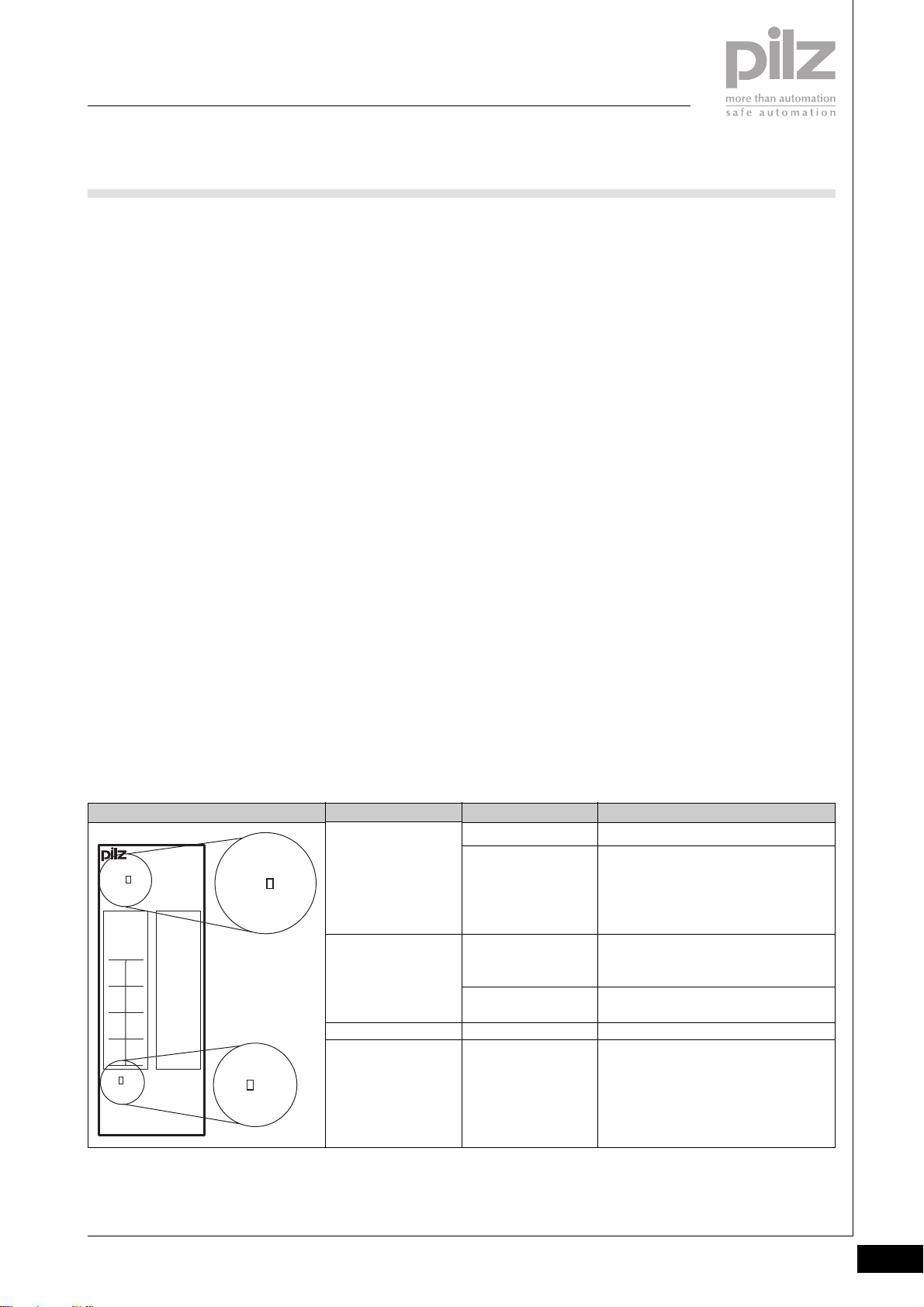
PSSuniversal
Supply voltage
PSSu E F BSW
Module diagnostics
` The module has various LEDs to
display
- Module errors (Err)
(see table)
` Error reaction:
- If an error occurs, the block
switching module switches off
the periphery supply to
subsequent (right-hand)
modules.
` SafetyBUS p error reaction:
If an error occurs, all the outputs
in the affected I/O-Group are shut
down safely and the I/O-Group
switches to a STOP condition. The
error is entered in the head
module’s error buffer.
System configuration
The system is configured using Pilz
configuration software.
Addressing the outputs
The outputs are addressed using Pilz
PSS WIN-PRO system software.
Supply voltage
` The supply voltages for module
supply and periphery supply may
be in the range of +18 VDC ... +30
VDC. Safe operation cannot be
guaranteed outside this range.
` Safe electrical isolation must be
ensured for the external 24 V
supplies. Failure to do so could
result in electric shock.
` The power supply must conform
to EN 60950, 03/97, section 2.3,
EN 60742, 9/95 or EN 50178,
10/97.
` To achieve the lowest possible
residual ripple (< ± 1.2 V), we
recommend that you install a
three-phase bridge rectifier or an
electronically regulated supply.
` The external periphery supply
must be able to provide a load
current of max. 10 A. On the
module bus, the load current of
max. 8 A must not be exceeded
for the periphery supply.
` The load current of max. 10 A
must not be exceeded on the Crail.
Wiring
` Connect together the 0 V
connections on all the 24 V power
supplies and earth the 0 V supply
at a single point.
` The connection of the 0 V supply
to the central earth bar or earth
fault monitor must be in accordance with relevant national
regulations (e.g. EN 60204-1,
NFPA 79:17-7, NEC: Article 250).
` Minimum range for cable cross
sections on connection terminals
in mm2, in accordance with EN
61131-2, 07/00:
- Power supply:
1.5 (AWG16) ... 2.5 (AWG12)
- Functional earth:
1.5 (AWG16) ... 2.5 (AWG12)
` Use copper wiring.
NOTICE
To prevent contact welding, a fuse
should be connected before the
output contacts (see technical
details).
2
LED
Err
Err
24V
312230
11 21
120V22
0V
13 23
24V 24V
14C24
C
SW
PSSu E F
BSW
Pilz GmbH & Co. KG, Sichere Automation, Felix-Wankel-Straße 2, 73760 Ostfildern, Germany
Telephone +49 711 3409-0, Telefax +49 711 3409-133, E-Mail: [email protected]
SW
Err
24V
24 V
SW
Off
Lights red
Off
Lights green
Off
Lights green
KeyLED statusElectronic module
Module is operating without error
Module error
(e.g.: error at the inputs, error in
programming mode, communication
error)
No supply voltage or
error in the supply voltage
for periphery supply
Supply voltage for periphery supply is
error-free
Periphery supply switched off
Periphery supply switched on
Status 01/05
2.2-33
Page 75
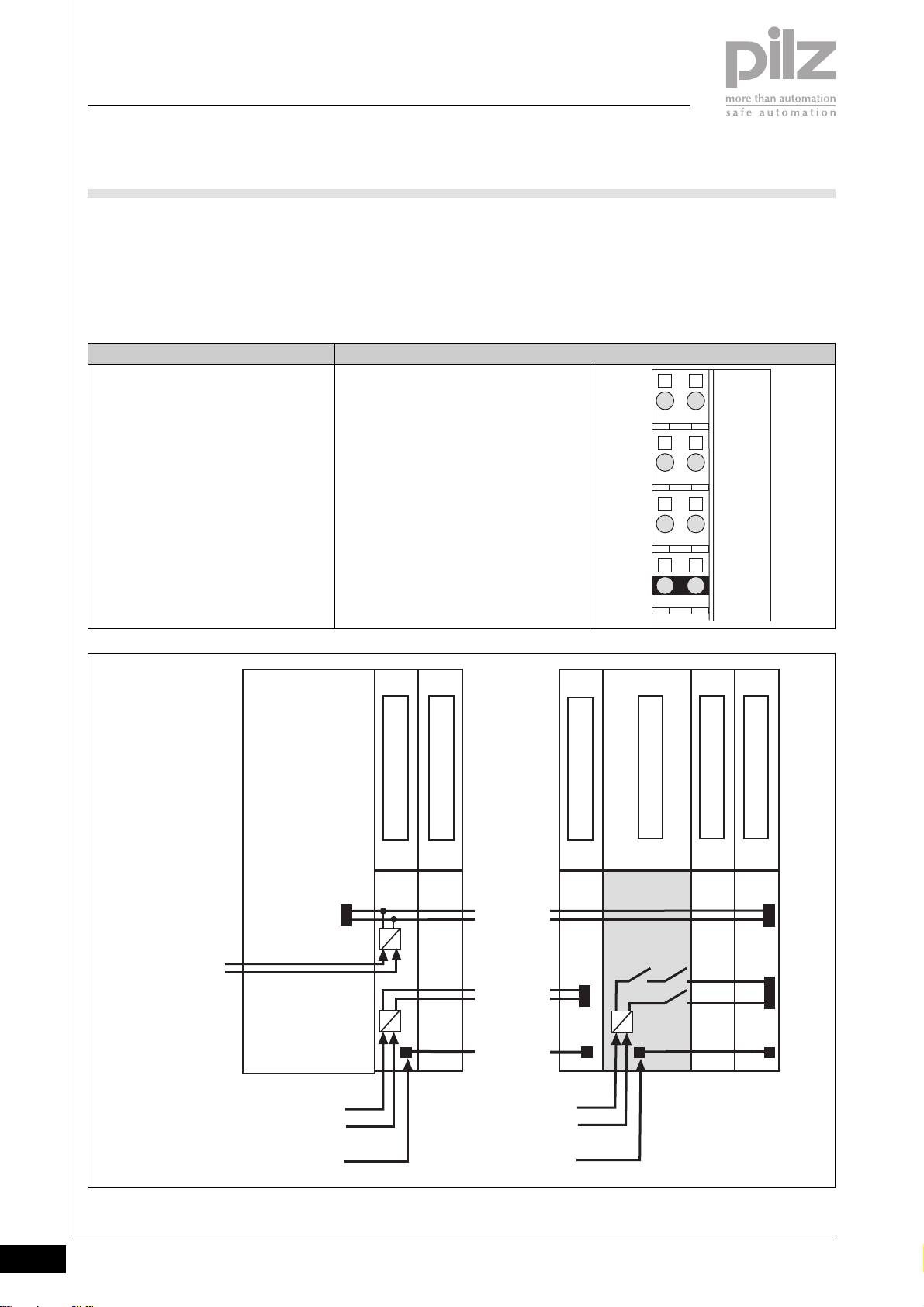
PSSuniversal
Supply voltage
PSSu E F BSW
Base modules
` Terminal configuration
Supply module
- To switch on/off the periphery
Base module Terminal configuration
Screw terminals:
PSSu BS 2/8S
Cage clamp terminals:
PSSu BS 2/8C
supply to input/output blocks
(block switching)
- To interrupt the incoming (lefthand) periphery supply and Crail supply
11: Not assigned
21: Not assigned
12-22: 0 V Periphery supply,
interrupted to the left
(12-22 linked internally)
13-23: +24 V Periphery supply,
interrupted to the left
(13-23 linked internally)
14-24: Infeed for C-rail supply, interrupted
to the left
(14-24 linked internally)
- To provide subsequent (righthand) modules with the
periphery supply and C-rail
supply
2111
2212
2313
2414
Module Supply
(24 V DC)
Head Module
Periphery Supply
(24 V DC)
C-rail
Supply
I/O Module
Power Supply
5 V DC
24 V DC
Periphery Supply
(24 V DC)
Block Switching
C-rail
Supply
[ . . . ]
Module Bus
[ . . . ]
I/O Module
24 V DC
PSSu E F BSW
I/O Module (ST)
I/O Module (ST)
2.2-34
Pilz GmbH & Co. KG, Sichere Automation, Felix-Wankel-Straße 2, 73760 Ostfildern, Germany
Telephone +49 711 3409-0, Telefax +49 711 3409-133, E-Mail: [email protected]
Status 01/05
Page 76
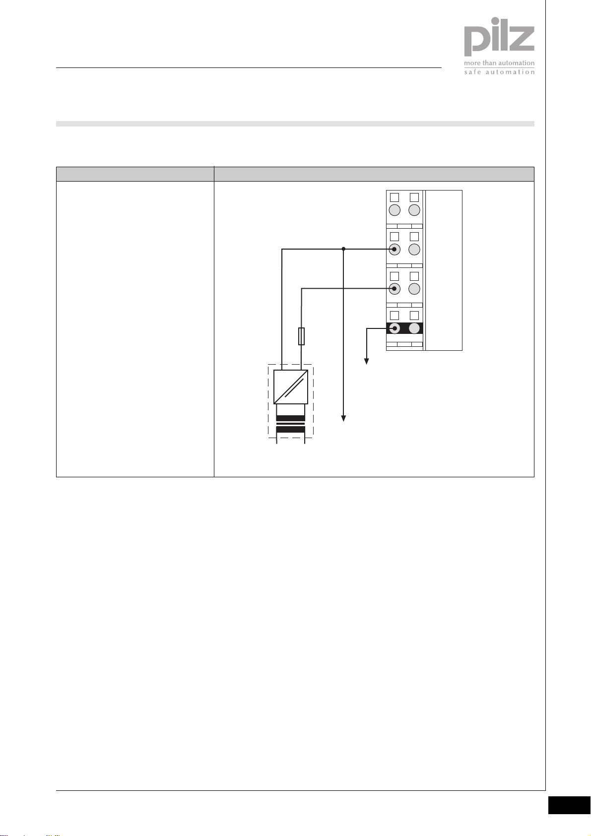
PSSuniversal
Supply voltage
PSSu E F BSW
` Connection
Supply to input/output blocks (block
switching)
with base module
- PSSu BS 2/8S or
- PSSu BS 2/8C
ConnectionSupply type
2111
0 V DC
2212
2
+24 V DC
2313
Fuse
10 A
=
~
NL1
Periphery Supply
2414
C-rail Supply
Connect to the 0 V supply and
earth this at a single point
Pilz GmbH & Co. KG, Sichere Automation, Felix-Wankel-Straße 2, 73760 Ostfildern, Germany
Telephone +49 711 3409-0, Telefax +49 711 3409-133, E-Mail: [email protected]
Status 01/05
2.2-35
Page 77

PSSuniversal
Supply voltage
PSSu E F BSW
Installation
` Horizontal installation is
preferable!
Vertical installation is possible, but
involves restrictions in terms of
temperature and vibration
resistance.
` The head module and supply
voltage module must already be
installed.
[1]
[2]
[3]
` Attach the base module to the DIN
rail to the right of the supply
voltage module [1] and click into
position on the rail [2].
` Slide the base module to the left
until you hear it click into the last
base module to be installed [3].
` If necessary:
- Label the connection levels
with coloured markers. To do
this, push the markers into the
recess below the fixing holes.
` Secure the final module on the
mounting rail with the appropriate
fixing bracket [4].
[4]
Wiring the module
` Refer also to the sections entitled
“Wiring” and “Base modules”
` Use a flat blade screwdriver (DIN
5264-A)
DIN 5264-A
` Strip the wire back 8 mm
` Actuators may be connected
using unscreened cables.
` If necessary, label the connection
level with a colour marker [7]
` Base module with cage clamp
terminals:
- Insert the screwdriver [8] into
the square opening [5]
- Insert the stripped cable into
the round fixing hole [6], as far
as it will go [9]
- Pull out the screwdriver [10]
` Base module with screw terminals:
- Use a screwdriver to open the
screw on the screw terminal [5]
- Insert the stripped cable into
the round fixing hole [6], as far
as it will go
- Use a screwdriver to tighten up
the screw on the screw terminal
[5].
[5]
2111
[6]
[7]
[8]
[9]
[10]
2.2-36
Pilz GmbH & Co. KG, Sichere Automation, Felix-Wankel-Straße 2, 73760 Ostfildern, Germany
Telephone +49 711 3409-0, Telefax +49 711 3409-133, E-Mail: [email protected]
Status 01/05
Page 78
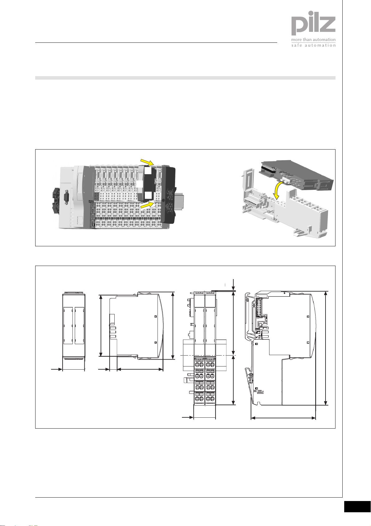
PSSuniversal
Supply voltage
PSSu E F BSW
Inserting an electronic module
NOTICE
Ensure that a correct contact is
made. A correct contact can no
longer be guaranteed when modules
have been inserted and removed
more than 20 times.
Dimensions
` Electronic modules should
preferably be inserted on to base
modules that are already installed
and wired.
` The electronic module must
audibly lock into position [1].
` Label the electronic module using
the labelling strips [2]
[1]
[2]
[1]
INFORMATION
The first time an electronic module is
inserted on to a base module, the
base module is protected from
plugging errors via a mechanical
coding element [3].
2
[3]
67,7 mm
25,2 mm
Using this data sheet
This data sheet is only intended for
use during configuration.
NOTICE
Please refer to the operating
manual during commissioning and
operation.
0,8 mm
76 mm
52,1 mm8,1 mm
56,1 mm 71,8 mm
25,2 mm
72,7 mm
128,9 mm
Pilz GmbH & Co. KG, Sichere Automation, Felix-Wankel-Straße 2, 73760 Ostfildern, Germany
Telephone +49 711 3409-0, Telefax +49 711 3409-133, E-Mail: [email protected]
Status 01/05
2.2-37
Page 79
PSSuniversal
Supply voltage
PSSu E F BSW
Technical details
Function
Application range
Electrical data
Supply voltage
Current consumption
Periphery supply
Load current, periphery supply
Max. switchable current at 25°C/60 °C
C-rail supply
Total current on C-rail at 24 VDC, +25 °C/+60 °C
Periphery supply buffer in the case of a power supply failure
Contact fuse protection on the external blow-out fuse
(VDE 0660)
Mechanical data
Weight
Electronic module
Base module with cage clamp terminals
Base module with screw terminals
Mechanical coding
Plug in/out cycles
Environmental data
Protection type (EN 60529, 02/00)
Ambient temperature
(EN 60068-2-14, 11/99)
Storage temperature (EN 60068-2-1/-2, 07/94)
Climatic suitability
(EN 60068-2-78, 10/01)
Condensation
Vibration (EN 60068-2-6, 04/95)
Shock
EN 60068-2-27, 03/93
EN 60068-2-29, 04/93
EMC
PSSu E F BSW
Block switching of the periphery supply for decentralised standard
applications of the PSSu series
Failsafe applications conforming to
EN 954-1, 03/97,
DIN V 19 250, 05/94,
DIN VDE 0116, 09/97,
EN IEC 61508, 12/98
From module supply: +5 VDC
From module supply: Max. 220 mA
+24 VDC
Max. 10 A
Max. 8 A/ max. 7 A
PE, screening, 0 V or 24 VDC ... +24 DC
Max. 10 A/ max. 8 A
None
10 A
90 g
Yellow, I
Max. 20
IP20
0 ... +60 °C
-25 ... +70 °C
93 % r.h. at 40 °C
Not permitted
Frequency range: 10 ... 57 Hz
Amplitude: 0.075 mm
Frequency range: 57 ... 150 Hz
Acceleration: 1g
15g, 11 ms
10g, 16 ms
EN 61000-6-2, 08/02
EN 61000-6-4, 08/02
2.2-38
Pilz GmbH & Co. KG, Sichere Automation, Felix-Wankel-Straße 2, 73760 Ostfildern, Germany
Telephone +49 711 3409-0, Telefax +49 711 3409-133, E-Mail: [email protected]
Status 01/05
Page 80
PSSuniversal
Supply voltage
PSSu E F BSW
Order reference
Description
PSSu E F BSW
(Electronic module)
PSSu BS 2/8S
(Base module with C-rail with screw terminals)
PSSu BS 2/8C
(Base module with C-rail with cage clamp terminals)
Order reference for accessories
Description
Operating manual in German
Operating manual in English
Operating manual in French
Operating manual in Spanish
Operating manual in Italian
Operating manual in Dutch
Order no.
312 230
312 656
312 657
Order no.
2
In progress
In progress
In progress
In progress
In progress
In progress
Pilz GmbH & Co. KG, Sichere Automation, Felix-Wankel-Straße 2, 73760 Ostfildern, Germany
Telephone +49 711 3409-0, Telefax +49 711 3409-133, E-Mail: [email protected]
Status 01/05
2.2-39
Page 81

PSSuniversal
Supply voltage
PSSu E F BSW
Notes
2.2-40
Pilz GmbH & Co. KG, Sichere Automation, Felix-Wankel-Straße 2, 73760 Ostfildern, Germany
Telephone +49 711 3409-0, Telefax +49 711 3409-133, E-Mail: [email protected]
Status 01/05
Page 82
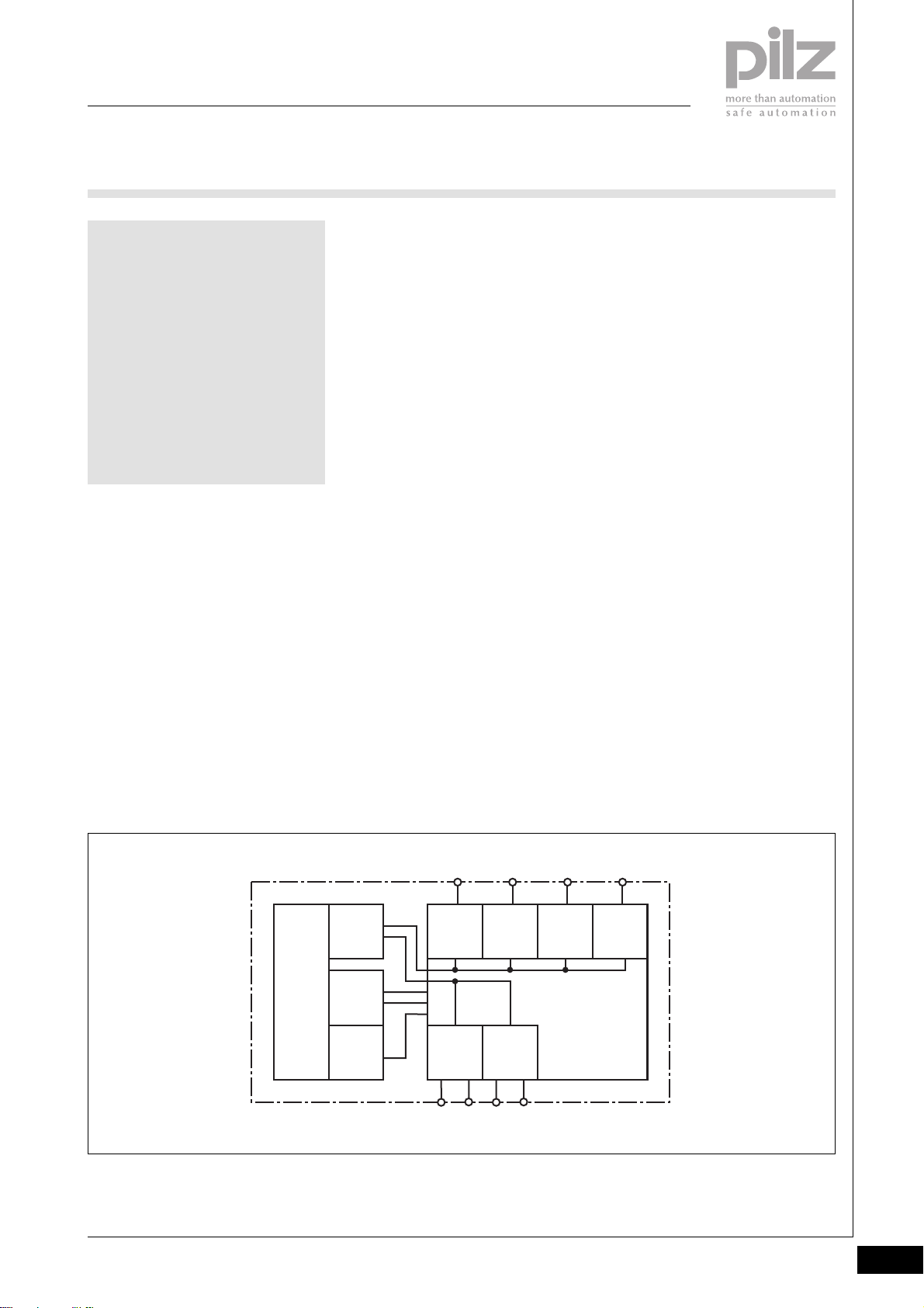
PSSuniversal
Digital input/output
PSSu E S 4DI
PSSu E S 4DI
not shown
Electronic module to detect 24 VDC
digital input signals. Suitable for nonsafety-related functions.
Module features
` Housing width: 12.6 mm
(1 x grid width)
` 4 digital inputs
` 2 outputs, with constant voltage of
+ 24 VDC
(Periphery supply)
` LED indicators for:
- Switch status of each input
- Module error
` Communication via
- Standard bus system
` Details of the base modules that
can be used are available under
“Terminal configuration” and
“Order reference”
Module description
The module may be used with input
devices for non-safety-related
functions.
Properties
` When the module supply is
interrupted, the electronics are
buffered for 20 ms, provided the
PSSu E F PS1 is used to supply
the system.
` Limited diagnostic capabilities
Block diagram
Periphery
Supply
+ 24 V DC
Module
Supply
+ 5 V DC
Mo dule Bus
Data
(ST)
Pilz GmbH & Co. KG, Sichere Automation, Felix-Wankel-Straße 2, 73760 Ostfildern, Germany
Telephone +49 711 3409-0, Telefax +49 711 3409-133, E-Mail: [email protected]
Input11Input21Input14Input
+ 24 V DC
12 22
+ 24 V DC
13 23
24
2.3-1
Page 83

PSSuniversal
Digital input/output
PSSu E S 4DI
Function description
` Module supply (5 VDC)
The electronics are supplied via
the module bus.
` Periphery supply (24 VDC)
The supply for the periphery (input
devices) is galvanically isolated
from the module supply. It is fed
from the module bus to terminals
on the base module (connection
level 2 and 3).
The periphery supply is not
switchable and has no current
limitation.
` Inputs
- Short circuit-proof
- The inputs have input filters.
- The head module signals the
input status to the relevant
controller via the bus system.
Signal detection at the inputs
To guarantee that a signal at an input
(“0” signal or “1” signal) is detected,
it must be present for a certain time
period.
If a signal (“0” signal or “1” signal)
does not exceed the pulse
suppression time, it is ignored. The
pulse suppression time depends on
the standard bus system.
2.3-2
Pilz GmbH & Co. KG, Sichere Automation, Felix-Wankel-Straße 2, 73760 Ostfildern, Germany
Telephone +49 711 3409-0, Telefax +49 711 3409-133, E-Mail: [email protected]
Page 84

PSSuniversal
Digital input/output
PSSu E S 4DI
Module diagnostics
` The module has various LEDs to
display
- Module errors (Err)
- Input status
(see table below)
` Error reaction:
The error reaction is determined
by the standard bus system.
Err
312400
11I021
I1
12 22
24V 24V
13 23
24V 24V
14I224
I3
111421
PSSu E S
4DI
24
Err
111421
24
System configuration
The system is configured using Pilz
configuration software and via the
standard bus system.
Addressing the inputs
The inputs are addressed via the
standard bus system.
LED KeyLED statusElectronic module
Err
11
14
21
24
Off
Lights red
Off
Lights green
Off
Lights green
Off
Lights green
Off
Lights green
Wiring
` Signals may be connected using
unscreened cables.
` Current limitation is required (e.g.
fuse) when the input devices are
supplied (periphery supply) via the
terminals on connection level 2
and 3.
Module is operating without error
Module error
(e.g.: error at the inputs, error in
programming mode, communication
error)
I0 = 0 signal (0 V)
I0 = 1 signal (min. 10 V)
I1 = 0 signal (0 V)
I1 = 1 signal (min. 10 V)
I2 = 0 signal (0 V)
I2 = 1 signal (min. 10 V)
I3 = 0 signal (0 V)
I3 = 1 signal (min. 10 V)
Pilz GmbH & Co. KG, Sichere Automation, Felix-Wankel-Straße 2, 73760 Ostfildern, Germany
Telephone +49 711 3409-0, Telefax +49 711 3409-133, E-Mail: [email protected]
2.3-3
Page 85
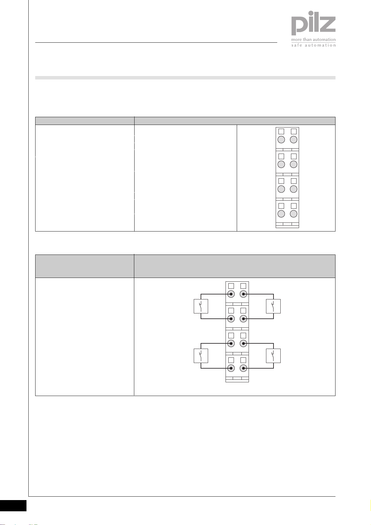
PSSuniversal
Digital input/output
PSSu E S 4DI
Base modules
` Terminal configuration
Base module Terminal configuration
Screw terminals:
PSSu BP 1/8S
Cage clamp terminals:
PSSu BP 1/8C
` Connection
Input circuit
Supplying the input devices via the
module’s periphery supply
Without C-rail:
11: I0 Input 1
21: I1 Input 2
12-22: 24 V + 24 V output
(Periphery supply
(12-22 linked internally)
13-23: 24 V + 24 V output
(Periphery supply
(13-23 linked internally)
14: I2 Input 3
24: I3 Input 4
Single-channel input device
PSSu BP 1/8S
PSSu BP 1/8C
2111
2212
2313
2414
I0
I1
2111
+ 24 V + 24 V
+ 24 V + 24 V
I2
2212
2313
I3
2414
2.3-4
Pilz GmbH & Co. KG, Sichere Automation, Felix-Wankel-Straße 2, 73760 Ostfildern, Germany
Telephone +49 711 3409-0, Telefax +49 711 3409-133, E-Mail: [email protected]
Page 86
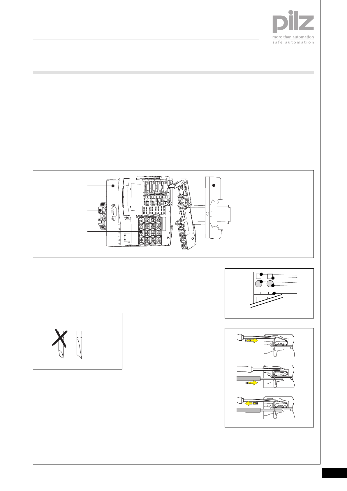
PSSuniversal
Digital input/output
PSSu E S 4DI
Installation
` Horizontal installation is
preferable!
Vertical installation is possible, but
involves restrictions in terms of
temperature and vibration
resistance.
` The head module and supply
voltage module must already be
installed.
[1]
[2]
[3]
` Attach the base module to the DIN
rail to the right of the supply
voltage module [1] and click into
position on the rail [2].
` Slide the base module to the left
until you hear it click into the last
base module to be installed [3].
` If necessary:
- Label the connection levels
with coloured markers. To do
this, push the markers into the
recess below the fixing holes.
` Secure the final module on the
mounting rail with the appropriate
fixing bracket [4].
[4]
Wiring the module
` Refer also to the sections entitled
“Wiring” and “Base modules”
` Use a flat blade screwdriver (DIN
5264-A)
DIN 5264-A
` Strip the wire back 8 mm
` Actuators may be connected
using unscreened cables.
` If necessary, label the connection
level with a colour marker [7]
` Base module with cage clamp
terminals:
- Insert the screwdriver [8] into
the square opening [5]
- Insert the stripped cable into
the round fixing hole [6], as far
as it will go [9]
- Pull out the screwdriver [10]
` Base module with screw terminals:
- Use a screwdriver to open the
screw on the screw terminal [5]
- Insert the stripped cable into
the round fixing hole [6], as far
as it will go
- Use a screwdriver to tighten up
the screw on the screw
terminal.
[5]
2111
[6]
[7]
[8]
[9]
[10]
Pilz GmbH & Co. KG, Sichere Automation, Felix-Wankel-Straße 2, 73760 Ostfildern, Germany
Telephone +49 711 3409-0, Telefax +49 711 3409-133, E-Mail: [email protected]
2.3-5
Page 87
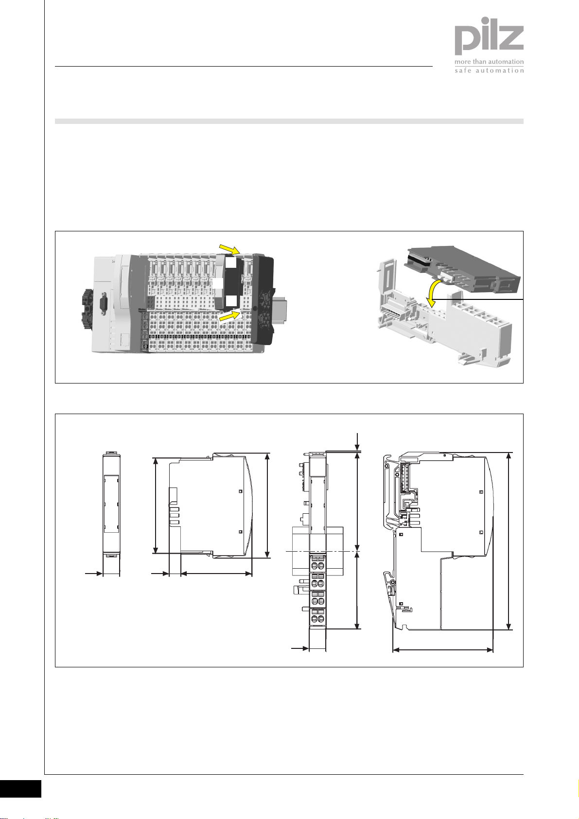
PSSuniversal
Digital input/output
PSSu E S 4DI
Inserting an electronic module
NOTICE
Ensure that a correct contact is
made. A correct contact can no
longer be guaranteed when modules
have been inserted and removed
more than 20 times.
Dimensions
` Electronic modules should
preferably be inserted on to base
modules that are already installed
and wired.
` The electronic module must
audibly lock into position [1].
` Label the electronic module using
the labelling strips [2]
[1]
[2]
[1]
INFORMATION
The first time an electronic module is
inserted on to a base module, the
base module is protected from
plugging errors via a mechanical
coding element [3].
[3]
67,7 mm
12,6 mm
Using this data sheet
This data sheet is only intended for
use during configuration.
NOTICE
Please refer to the operating
manual during commissioning and
operation.
0,8 mm
76 mm
52,1 mm8,1 mm
56,1 mm 71,8 mm
12,6 mm
72,6 mm
128,9 mm
2.3-6
Pilz GmbH & Co. KG, Sichere Automation, Felix-Wankel-Straße 2, 73760 Ostfildern, Germany
Telephone +49 711 3409-0, Telefax +49 711 3409-133, E-Mail: [email protected]
Page 88
PSSuniversal
Digital input/output
PSSu E S 4DI
Technical details
Function
Application range
Electrical data
Supply voltage
Current consumption
Integral on-board inputs
Number
Signal level at “0”
Signal level at “1”
Input current
Pulse suppression
Status indicator
Mechanical data
Weight
Electronic module
Base module with cage clamp terminals
Base module with screw terminals
Mechanical coding
Plug in/out cycles
Electronic module
Base module
Max. cross section of external conductors with screw terminals
Flexible with crimp connectors
Flexible or rigid without crimp connectors
Max. cross section of external conductors with cage clamp
terminals
Flexible with crimp connectors
Flexible or rigid without crimp connectors
Torque setting with screw terminals
Environmental data
Protection type (EN 60529, 02/00)
Ambient temperature
(EN 60068-2-14, 11/99)
Storage temperature (EN 60068-2-1/-2, 07/94)
Climatic suitability
(EN 60068-2-78, 10/01)
Condensation
Vibration (EN 60068-2-6, 04/95)
Shock (EN 60068-2-27, 03/93)
Continuous shock (EN 60068-2-29, 04/93)
EMC
PSSu E S 4DI
Compact programmable safety system for decentralised
applications
Standard applications
From module supply: 5 VDC
From module supply: ≤ 25 mA
4
-3 ... +5 VDC
+15 ... +30 VDC
2.5 ... 8 mA
< 3 ms
LED
35 g
40 g
50 g
Dark grey, A
Max. 20
Max. 20
0.5 ... 1.5 mm
0.5 ... 2.5 mm
0.5 ... 1.5 mm
0.5 ... 1.5 mm
0.8 Nm
IP20
0 ... +60 °C
-25 ... +70 °C
93 % r.h. at 40 °C
Not permitted
Frequency range: 10 ... 57 Hz
Amplitude: 0.075 mm
Frequency range: 57 ... 150 Hz
Acceleration: 1g
15g, 11 ms
10g, 16 ms
EN 61000-6-2, 08/02
EN 61000-6-4, 08/02
2
2
2
2
Pilz GmbH & Co. KG, Sichere Automation, Felix-Wankel-Straße 2, 73760 Ostfildern, Germany
Telephone +49 711 3409-0, Telefax +49 711 3409-133, E-Mail: [email protected]
2.3-7
Page 89
PSSuniversal
Digital input/output
PSSu E S 4DI
Order reference
Description
PSSu E S 4DI
(Electronic module)
PSSu BP 1/8S
(Base module without C-rail with screw terminals)
PSSu BP 1/8C
(Base module without C-rail with cage clamp terminals)
Order reference for accessories
Description
Operating manual in German
Operating manual in English
Operating manual in French
Operating manual in Spanish
Operating manual in Italian
Operating manual in Dutch
Order no.
312 400
312 600
312 601
Order no.
In progress
In progress
In progress
In progress
In progress
In progress
2.3-8
Pilz GmbH & Co. KG, Sichere Automation, Felix-Wankel-Straße 2, 73760 Ostfildern, Germany
Telephone +49 711 3409-0, Telefax +49 711 3409-133, E-Mail: [email protected]
Page 90

PSSuniversal
Digital input/output
PSSu E S 4DO 0.5
PSSu E S 4DO 0.5
not shown
Electronic module to output 24 VDC
digital output signals. Suitable for
non-safety-related functions.
Module features
` Housing width: 12.6 mm
(1 x grid width)
` 4 single-pole digital outputs
- Positive-switching
- Current load capacity per
output: max. 0.5 A
- Short circuit-proof
- Overload-proof
` LED indicators for:
- Switch status of each output
- Module error
` Communication via
- Standard bus system
` Details of the base modules that
can be used are available under
“Base modules” and “Order
reference”.
Module description
The module may be used for nonsafety-related switching of
` Resistive loads with max. 0.5 A
per output
` Inductive loads with max. 0.5 A
per output
Properties
` When the module supply is
interrupted, the electronics are
buffered for 20 ms, provided the
PSSu E F PS1 is used to supply
the system.
` Limited diagnostic capabilities
2
Block diagram
12 22
Periphery
Supply
+ 24 V DC
Module
Supply
+ 5 V DC
Mo dule Bus
Data
(FS)
0 V Periphery Supply/cross connection
13 23
Pilz GmbH & Co. KG, Sichere Automation, Felix-Wankel-Straße 2, 73760 Ostfildern, Germany
Telephone +49 711 3409-0, Telefax +49 711 3409-133, E-Mail: [email protected]
Output11Output21Output14Output
24
Status 01/05
2.3-9
Page 91

PSSuniversal
Digital input/output
PSSu E S 4DO 0.5
Function description
` Module supply (5 VDC)
The electronics are supplied via
the module bus.
` Periphery supply (24 VDC)
The supply to the outputs is
galvanically isolated from the
module supply.
` “0” signal (0 V) at the output:
- Output is high impedance
- No current to the load
` “1” signal (+24 V) at the output:
- Output is low impedance
- Current is supplied to the load
2.3-10
Pilz GmbH & Co. KG, Sichere Automation, Felix-Wankel-Straße 2, 73760 Ostfildern, Germany
Telephone +49 711 3409-0, Telefax +49 711 3409-133, E-Mail: [email protected]
Status 01/05
Page 92
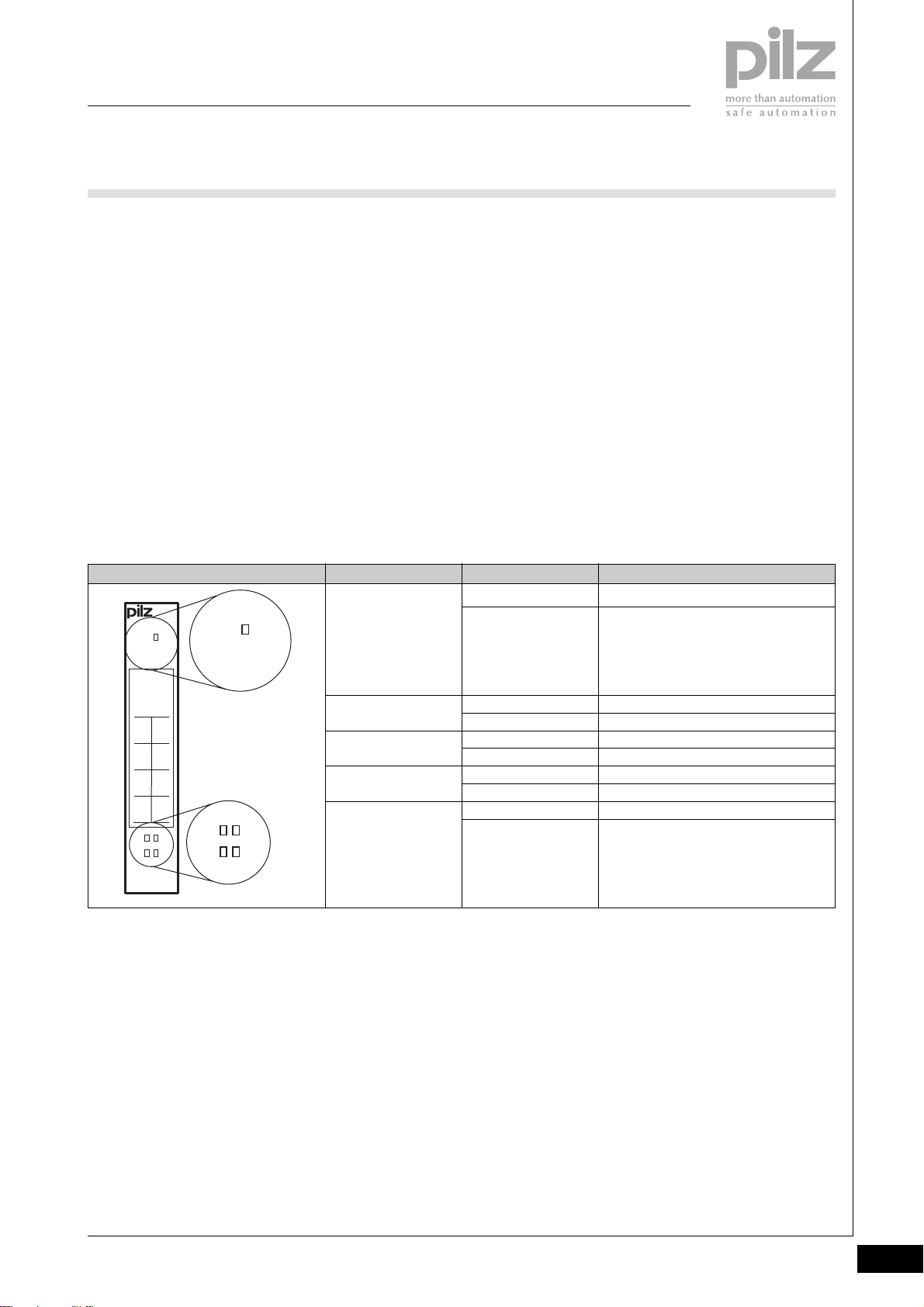
PSSuniversal
Digital input/output
PSSu E S 4DO 0.5
Module diagnostics
` The module has various LEDs to
display
- Module errors (Err)
- Output status
(see table below)
` Error reaction:
The error reaction is determined
by the standard bus system.
Err
312405
Err
System configuration
The system is configured using Pilz
configuration software and via the
standard bus system.
Addressing the outputs
The outputs are addressed via the
standard bus system.
LED KeyLED statusElectronic module
Err
Off
Lights red
Wiring
` Actuators may be connected
using unscreened cables.
` When switching inductive loads,
suppression should not be used to
protect the semiconductor
outputs. If suppression cannot be
avoided (e.g. on contactors with
integral suppression), errors may
occur, particulary with RC
elements, depending on their
capacitive share.
Module is operating without error
Module error
(e.g.: error at the inputs, error in
programming mode, communication
error)
2
11O021
O1
120V22
0V
13
(C)23(C)
14O224
O3
111421
24
PSSu E S
4DO 0.5
111421
24
11
14
21
24
Off
Lights green
Off
Lights green
Off
Lights green
Off
Lights green
O0 = 0 signal (0 V)
O0 = 1 signal (min. 10 V)
O1 = 0 signal (0 V)
O1 = 1 signal (min. 10 V)
O2 = 0 signal (0 V)
O2 = 1 signal (min. 10 V)
O3 = 0 signal (0 V)
O3 = 1 signal (min. 10 V)
Pilz GmbH & Co. KG, Sichere Automation, Felix-Wankel-Straße 2, 73760 Ostfildern, Germany
Telephone +49 711 3409-0, Telefax +49 711 3409-133, E-Mail: [email protected]
Status 01/05
2.3-11
Page 93
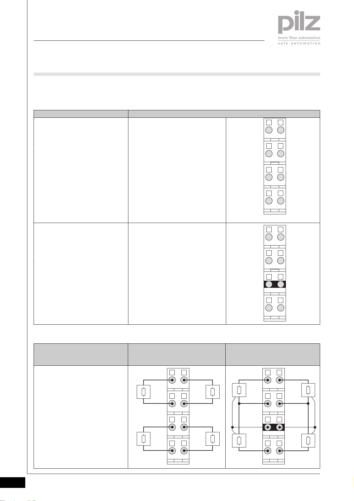
PSSuniversal
Digital input/output
PSSu E S 4DO 0.5
Base modules
` Terminal configuration
Base module Terminal configuration
Screw terminals:
PSSu BP 1/8S
Cage clamp terminals:
PSSu BP 1/8C
Screw terminals:
PSSu BP-C 1/8S
Cage clamp terminals:
PSSu BP-C 1/8C
Without C-rail:
11: O0 Output 1, single-pole
21: O1 Output 2, single-pole
12-22: 0 V Periphery supply
(12-22 linked internally)
13-23: 0 V Periphery supply
(13-23 linked internally)
14: O2 Output 3, single-pole
24: O3 Output 4, single-pole
With C-rail:
11: O0 Output 1, single-pole
21: O1 Output 2, single-pole
12-22: 0 V Periphery supply
(12-22 linked internally)
13-23: C-rail supply
(13-23 linked internally)
14: O2 Output 3, single-pole
24: O3 Output 4, single-pole
2111
2212
2313
2414
2111
2212
2313
2.3-12
` Connection
Output circuit
` Resistive load/capacitive load
` Single-channel actuator
Pilz GmbH & Co. KG, Sichere Automation, Felix-Wankel-Straße 2, 73760 Ostfildern, Germany
Telephone +49 711 3409-0, Telefax +49 711 3409-133, E-Mail: [email protected]
Without C-rail
PSSu BP 1/8S
PSSu BP 1/8C
O0 O1
0 V
0 V 0 V
O2
2111
0 V
2212
2313
O3
2414
With C-rail
PSSu BP 1/8S
PSSu BP 1/8C
2414
O0
0 V
PE PE
O2
O1
2111
2212
0 V
2313
O3
2414
Status 01/05
Page 94
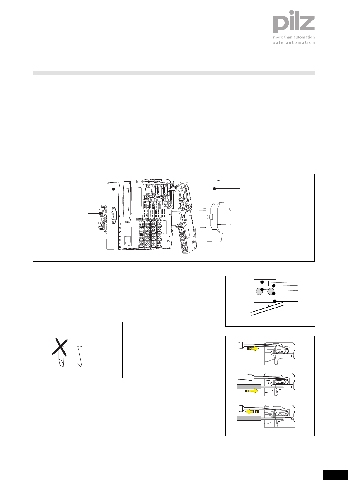
PSSuniversal
Digital input/output
PSSu E S 4DO 0.5
Installation
` Horizontal installation is
preferable!
Vertical installation is possible, but
involves restrictions in terms of
temperature and vibration
resistance.
` The head module and supply
voltage module must already be
installed.
[1]
[2]
[3]
` Attach the base module to the DIN
rail to the right of the supply
voltage module [1] and click into
position on the rail [2].
` Slide the base module to the left
until you hear it click into the last
base module to be installed [3].
` If necessary:
- Label the connection levels
with coloured markers. To do
this, push the markers into the
recess below the fixing holes.
` Secure the final module on the
mounting rail with the appropriate
fixing bracket [4].
2
[4]
Wiring the module
` Refer also to the sections entitled
“Wiring” and “Base modules”
` Use a flat blade screwdriver (DIN
5264-A)
DIN 5264-A
` Strip the wire back 8 mm
` Actuators may be connected
using unscreened cables.
` If necessary, label the connection
level with a colour marker [7]
` Base module with cage clamp
terminals:
- Insert the screwdriver [8] into
the square opening [5]
- Insert the stripped cable into
the round fixing hole [6], as far
as it will go [9]
- Pull out the screwdriver [10]
` Base module with screw terminals:
- Use a screwdriver to open the
screw on the screw terminal [5]
- Insert the stripped cable into
the round fixing hole [6], as far
as it will go
- Use a screwdriver to tighten up
the screw on the screw terminal
[5].
[5]
2111
[6]
[7]
[8]
[9]
[10]
Pilz GmbH & Co. KG, Sichere Automation, Felix-Wankel-Straße 2, 73760 Ostfildern, Germany
Telephone +49 711 3409-0, Telefax +49 711 3409-133, E-Mail: [email protected]
Status 01/05
2.3-13
Page 95
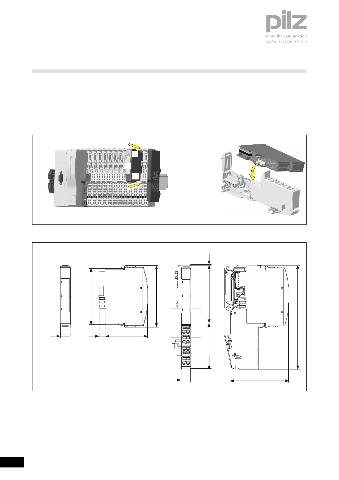
PSSuniversal
Digital input/output
PSSu E S 4DO 0.5
Inserting an electronic module
NOTICE
Ensure that a correct contact is
made. A correct contact can no
longer be guaranteed when modules
have been inserted and removed
more than 20 times.
Dimensions
` Electronic modules should
preferably be inserted on to base
modules that are already installed
and wired.
` The electronic module must
audibly lock into position [1].
` Label the electronic module using
the labelling strips [2]
[1]
[2]
[1]
INFORMATION
The first time an electronic module is
inserted on to a base module, the
base module is protected from
plugging errors via a mechanical
coding element [3].
[3]
67,7 mm
12,6 mm
Using this data sheet
This data sheet is only intended for
use during configuration.
NOTICE
Please refer to the operating
manual during commissioning and
operation.
0,8 mm
76 mm
52,1 mm8,1 mm
56,1 mm 71,8 mm
12,6 mm
72,6 mm
128,9 mm
2.3-14
Pilz GmbH & Co. KG, Sichere Automation, Felix-Wankel-Straße 2, 73760 Ostfildern, Germany
Telephone +49 711 3409-0, Telefax +49 711 3409-133, E-Mail: [email protected]
Status 01/05
Page 96
PSSuniversal
Digital input/output
PSSu E S 4DO 0.5
Technical details
Function
Application range
Electrical data
Supply voltage
Current consumption
Outputs – single-pole
Number
Potential isolation
Output current at “1”
Permitted range
Short circuit protection
Residual current at “0” signal
Signal level at “0”
Signal level at “1”
Status indicator
Mechanical data
Weight
Electronic module
Base module with cage clamp terminals
Base module with screw terminals
Mechanical coding
Plug in/out cycles
Electronic module
Base module
Max. cross section of external conductors with screw terminals
Flexible with crimp connectors
Flexible or rigid without crimp connectors
Max. cross section of external conductors with cage clamp
terminals
Flexible with crimp connectors
Flexible or rigid without crimp connectors
Torque setting with screw terminals
Environmental data
Protection type (EN 60529, 02/00)
Ambient temperature
(EN 60068-2-14, 11/99)
Storage temperature (EN 60068-2-1/-2, 07/94)
Climatic suitability
(EN 60068-2-78, 10/01)
Condensation
Vibration (EN 60068-2-6, 04/95)
Shock
EN 60068-2-27, 03/93
EN 60068-2-29, 04/93
EMC
PSSu E F 4DO 0.5
Compact programmable safety system for decentralised
applications
Standard applications
From module supply: 5 VDC
From module supply: ≤ 60 mA
4
Yes (optocoupler)
0.5 A
0 ... 0.75 A
Electronic
0 mA
0 VDC
UB -0.2 VDC at 0.5 A
LED
< 40 g
40 g
50 g
Dark grey, B
Max. 20
Max. 20
0.5 ... 1.5 mm
0.5 ... 2.5 mm
0.5 ... 1.5 mm
0.5 ... 1.5 mm
0.8 Nm
IP20
0 ... +60 °C
-25 ... +70 °C
93 % r.h. at 40 °C
Not permitted
Frequency range: 10 ... 57 Hz
Amplitude: 0.075 mm
Frequency range: 57 ... 150 Hz
Acceleration: 1g
15g, 11 ms
10g, 16 ms
EN 61000-6-2, 08/02
EN 61000-6-4, 08/02
2
2
2
2
2
Pilz GmbH & Co. KG, Sichere Automation, Felix-Wankel-Straße 2, 73760 Ostfildern, Germany
Telephone +49 711 3409-0, Telefax +49 711 3409-133, E-Mail: [email protected]
Status 01/05
2.3-15
Page 97
PSSuniversal
Digital input/output
PSSu E S 4DO 0.5
Order reference
Description
PSSu E S 4DO 0.5
(Electronic module)
PSSu BP 1/8S
(Base module without C-rail with screw terminals)
PSSu BP 1/8C
(Base module without C-rail with cage clamp terminals)
PSSu BP-C 1/8S
(Base module with C-rail with screw terminals)
PSSu BP-C 1/8C
(Base module with C-rail with cage clamp terminals)
Order reference for accessories
Description
Operating manual in German
Operating manual in English
Operating manual in French
Operating manual in Spanish
Operating manual in Italian
Operating manual in Dutch
Order no.
312 405
312 600
312 601
312 610
312 611
Order no.
In progress
In progress
In progress
In progress
In progress
In progress
2.3-16
Pilz GmbH & Co. KG, Sichere Automation, Felix-Wankel-Straße 2, 73760 Ostfildern, Germany
Telephone +49 711 3409-0, Telefax +49 711 3409-133, E-Mail: [email protected]
Status 01/05
Page 98
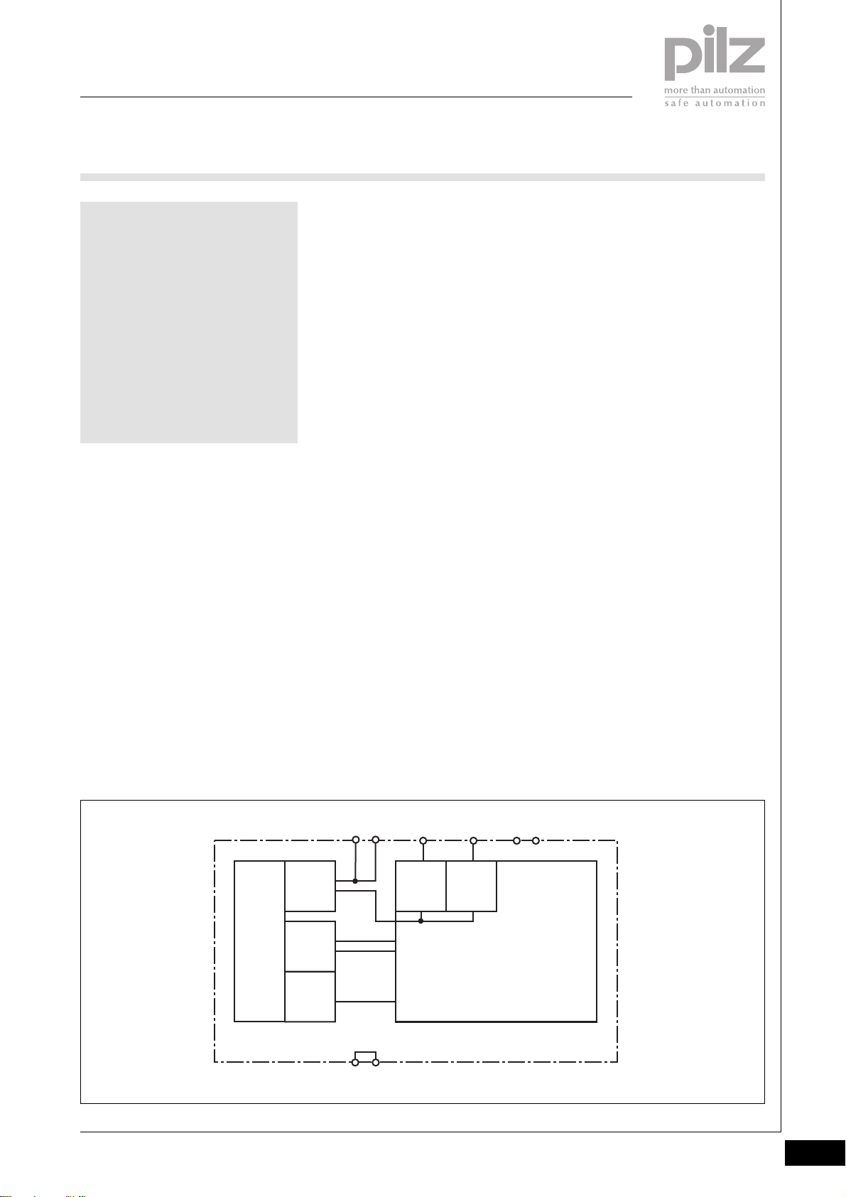
PSSuniversal
Digital input/output
PSSu E S 2DO 2
PSSu E S 2DO 2
not shown
Electronic module to output 24 VDC
digital output signals. Suitable for
non-safety-related functions.
Module features
` Housing width: 12.6 mm
(1 x grid width)
` 2 single-pole digital outputs
- Positive-switching
- Current load capacity per
output: max. 2 A
- Short circuit-proof
- Overload-proof
` LED indicators for:
- Switch status of each output
- Module error
` Communication via
- Standard bus system
` Details of the base modules that
can be used are available under
“Base modules” and “Order
reference”.
Module description
The module may be used for nonsafety-related switching of
` Resistive loads with max. 2 A per
output
` Inductive loads with max. 2 A per
output
Properties
` When the module supply is
interrupted, the electronics are
buffered for 20 ms, provided the
PSSu E F PS1 is used to supply
the system.
` Limited diagnostic capabilities
2
Block diagram
12 22
Periphery
Supply
+ 24 V DC
Module
Supply
+ 5 V DC
Mo dule Bus
Data
(ST)
0V Periphery Supply/cross connection
13 23
Pilz GmbH & Co. KG, Sichere Automation, Felix-Wankel-Straße 2, 73760 Ostfildern, Germany
Telephone +49 711 3409-0, Telefax +49 711 3409-133, E-Mail: [email protected]
Output11Output
21
14 24
Status 01/05
2.3-17
Page 99

PSSuniversal
Digital input/output
PSSu E S 2DO 2
Function description
` Module supply (5 VDC)
The electronics are supplied via
the module bus.
` Periphery supply (24 VDC)
The supply to the outputs is
galvanically isolated from the
module supply.
` “0” signal (0 V) at the output:
- Output is high impedance
- No current to the load
` “1” signal (+24 V) at the output:
- Output is low impedance
- Current is supplied to the load
2.3-18
Pilz GmbH & Co. KG, Sichere Automation, Felix-Wankel-Straße 2, 73760 Ostfildern, Germany
Telephone +49 711 3409-0, Telefax +49 711 3409-133, E-Mail: [email protected]
Status 01/05
Page 100
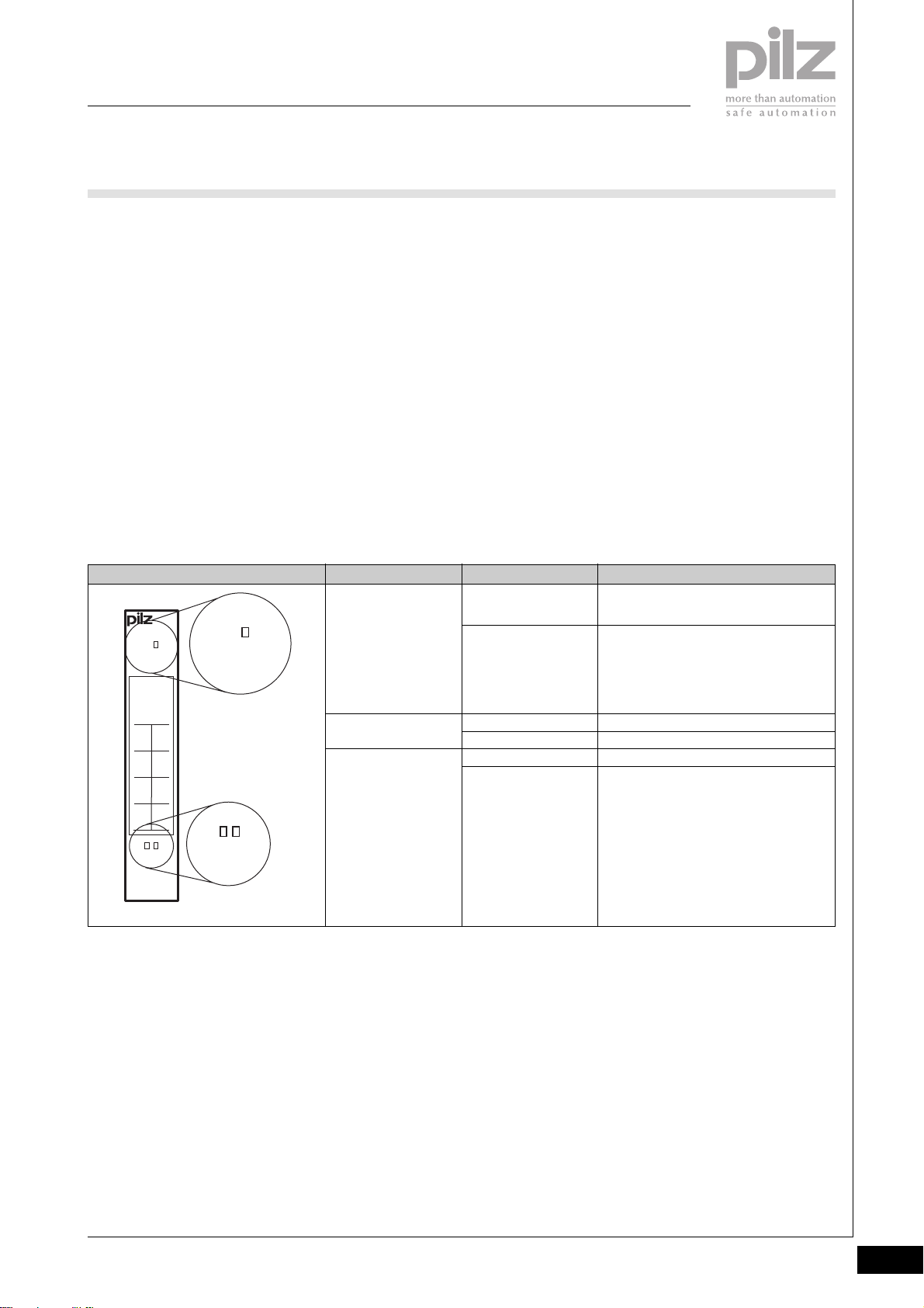
PSSuniversal
Digital input/output
PSSu E S 2DO 2
Module diagnostics
` The module has various LEDs to
display
- Module errors (Err/FS1)
- Output status
(see table below)
` Error reaction:
The error reaction is determined
by the standard bus system.
Err
Err
312410
System configuration
The system is configured using Pilz
configuration software and via the
standard bus system.
Addressing the outputs
The inputs are addressed via the
standard bus system.
LED KeyLED statusElectronic module
Err
Off
Lights red
Wiring
` Actuators may be connected
using unscreened cables.
` When switching inductive loads,
suppression should not be used to
protect the semiconductor
outputs. If suppression cannot be
avoided (e.g. on contactors with
integral suppression), errors may
occur, particulary with RC
elements, depending on their
capacitive share.
Module is operating without error,
No FS enable for output O1
Module error
(e.g.: error at the inputs, error in
programming mode, communication
error)
2
11O021
O1
120V22
0V
13
(C)23(C)
14 24
11 21
PSSu E S
2DO 2
11 21
11
14
Off
Lights green
Off
Lights green
O0 = 0 signal (0 V)
O0 = 1 signal (min. 10 V)
O1 = 0 signal (0 V)
O1 = 1 signal (min. 10 V)
Pilz GmbH & Co. KG, Sichere Automation, Felix-Wankel-Straße 2, 73760 Ostfildern, Germany
Telephone +49 711 3409-0, Telefax +49 711 3409-133, E-Mail: [email protected]
Status 01/05
2.3-19
 Loading...