

Page 1

Operating Manual PSSu K S RS232 Modbus AS CII
Operating Manual PSSu K S RS232 Modbus ASCII
PSSu K S RS232 Modbus ASCII
Decentralised system PSSuniversal I/O
Operating Manual — No. 1001689-EN-04
Page 2

This document is a translation of the original document.
All rights to this documentation are reserved by Pilz GmbH & Co. KG. Copies may be made
for internal purposes.
Suggestions and comments for improving this documentation will be gratefully received.
Pilz®, PIT®, PMI®, PNOZ®, Primo®, PSEN®, PSS®, PVIS®, SafetyBUS p®, SafetyEYE®,
SafetyNET p®, the spirit of safety® are registered and protected trademarks of
Pilz GmbH & Co. KG in some countries.
SD means Secure Digital.
Preface
Page 3

Contents
Contents
Contents Page
Chapter 1 Introduction
1.1 Validity of documentation 1-1
1.1.1 Retaining the documentation 1-1
1.1.2 Terminology: System environment A and B 1-1
1.2 Overview of documentation 1-2
1.3 Definition of symbols 1-3
Chapter 2 Overview
2.1 Module structure 2-1
2.1.1 Module features 2-1
2.2 Front view 2-2
Chapter 3 Safety
3.1 Intended use 3-1
3.2 Safety regulations 3-2
3.2.1 Use of qualified personnel 3-2
3.2.2 Warranty and liability 3-2
3.2.3 Disposal 3-2
Chapter 4 Function description
4.1 Module features 4-1
4.1.1 Function description 4-1
4.1.2 Integrated protection mechanisms 4-1
4.2 Data exchange 4-2
4.3 Configuration 4-3
4.3.1 Interface parameters 4-3
4.3.2 Receive buffer threshold 4-3
Chapter 5 Installation
5.1 General installation guidelines 5-1
5.1.1 Dimensions 5-1
5.2 Install compact module 5-2
Chapter 6 Wiring
6.1 Interface configuration 6-1
6.1.1 RS232 interface 6-1
Chapter 7 Operation
7.1 Messages 7-1
7.2 Display elements 7-2
7.2.1 Display element for operational readiness 7-2
7.2.2 Display element for module error 7-2
7.2.3 Display elements for data transmission 7-3
Pilz GmbH & Co. KG, Felix-Wankel-Straße 2, 73760 Ostfildern, Germany
Telephone: +49 711 3409-0, Telefax: +49 711 3409-133, E-Mail: pilz.gmbh@pilz.de
1
Page 4

Contents
Chapter 8 Technical details
8.1 Technical details 8-1
8.2 Order reference 8-3
Pilz GmbH & Co. KG, Felix-Wankel-Straße 2, 73760 Ostfildern, Germany
2
Telephone: +49 711 3409-0, Telefax: +49 711 3409-133, E-Mail: pilz.gmbh@pilz.de
Page 5

1 Introduction
1.1 Validity of documentation
11000IntroductionIntroduction1-1.1Validity of docume ntation1100Validity of documenta tion1-Einf Gltigkeit der Dokumentation
This documentation is valid for the product PSSu K S RS232 Modbus
Einf Einleitung
1.1.1 Retaining the documentation
Retaining the documentation1-Einf Aufbewahren
ASCII. It is valid until new documentation is published.
This operating manual explains the function and operation, describes
the installation and provides guidelines on how to connect the product.
This documentation is intended for instruction and should be retained
for future reference.
1.1.2 Terminology: System environment A and B
Terminology: System environment A and B1-][BA Einf Begriffsdefinition Sys A + B
The PSSu system can be used in two different system environments.
The module's application area is described in the chapter "Intended
Use" of the manual.
The distinction is made between
PSSu in system environment A
PSSu in system environment B
The distinction is based on the application area of the PSSu system.
PSSu in system environment A may be used in the
Decentralised system PSSu I/O with SafetyBUS p
Decentralised system PSSu I/O with ST fieldbuses such as CANopen,
DeviceNet
Not in the automation system PSS 4000
PSSu in system environment B may be used in the
Automation system PSS 4000, e.g. with the
– Decentralised system PSSu I/O with SafetyNET p
– Control system PSSu PLC
– Control system PSSu multi
][BA Einf Begriffsdefinition Zusatz Sys B
The module PSSu K S RS232 Modbus ASCII is exclusively for use in
system environment B (automation system PSS 4000).
Pilz GmbH & Co. KG, Felix-Wankel-Straße 2, 73760 Ostfildern, Germany
Telephone: +49 711 3409-0, Telefax: +49 711 3409-133, E-Mail: pilz.gmbh@pilz.de
1-1
Page 6

1 Introduction
1.2 Overview of documentation
1.2Overview of documentation1200Overview of documentation1-][BA Einf Übersicht E-Modul
1 Introduction
The introduction is designed to familiarise you with the contents, structure and specific order of this manual.
2 Overview
This chapter provides information on the product's most important features.
3 Safety
This chapter must be read as it contains important information on safety
and intended use.
4 Function Description
This chapter describes the product's individual components.
5 Installation
This chapter explains how to install the product.
6 Wiring
This chapter describes the product's wiring.
7 Operation
This chapter explains the display elements and advises on what to do if
a fault occurs.
8 Technical Details
This chapter contains the product's technical details and order reference.
1-2
Pilz GmbH & Co. KG, Felix-Wankel-Straße 2, 73760 Ostfildern, Germany
Telephone: +49 711 3409-0, Telefax: +49 711 3409-133, E-Mail: pilz.gmbh@pilz.de
Page 7
1 Introduction
1.3 Definition of symbols
1.3Definition of symbols1300Definition of symbols1-Einfhrung Zeichen
Information that is particularly important is identified as follows:
DANGER!
This warning must be heeded! It warns of a hazardous situation
that poses an immediate threat of serious injury and death and
indicates preventive measures that can be taken.
WARNING!
This warning must be heeded! It warns of a hazardous situation
that could lead to serious injury and death and indicates preventive measures that can be taken.
CAUTION!
This refers to a hazard that can lead to a less serious or minor
injury plus material damage, and also provides information on
preventive measures that can be taken.
NOTICE
This describes a situation in which the unit(s) could be damaged
and also provides information on preventive measures that can
be taken. It also highlights areas within the text that are of particular importance.
INFORMATION
This gives advice on applications and provides information on
special features.
Pilz GmbH & Co. KG, Felix-Wankel-Straße 2, 73760 Ostfildern, Germany
Telephone: +49 711 3409-0, Telefax: +49 711 3409-133, E-Mail: pilz.gmbh@pilz.de
1-3
Page 8

1 Introduction
1-4
Pilz GmbH & Co. KG, Felix-Wankel-Straße 2, 73760 Ostfildern, Germany
Telephone: +49 711 3409-0, Telefax: +49 711 3409-133, E-Mail: pilz.gmbh@pilz.de
Page 9

2 Overview
2.1 Module structure
22000OverviewOverview2-2.1Module structure2100Module structure2-][BA Übersicht Aufbau K Trumph
The module combines the function unit (inputs or outputs, interfaces)
and connection levels in one housing.
Wiring is via Sub-D female and male connectors
2.1.1 Module features
Module features2-Geraetemerkmale_Zusatz BA Einleitung
Merkmale_Ein_Aus
][Merkmale_Ein_Aus RS232 Ser
][Merkmale_LED ST Ser
][Merkmale_Zusatz ST-Module Sys B
The product has the following features:
Data exchange based on the Modbus ASCII protocol
Serial interface: RS 232
Communication channels: 2 (Tx/Rx, full duplex)
Configurable transmission rates
Receive buffer: 1023 Byte
Send buffer: 127 Byte
Max. number per system: 6
LEDs for:
– Operational readiness
– Module error
– Data transmission
For standard applications in system environment B (automation sys-
tem PSS 4000)
Pilz GmbH & Co. KG, Felix-Wankel-Straße 2, 73760 Ostfildern, Germany
Telephone: +49 711 3409-0, Telefax: +49 711 3409-133, E-Mail: pilz.gmbh@pilz.de
2-1
Page 10
2 Overview
RS232
Modbus
ASCII
PSSu K S RS232
Modbus ASCII
1
2
3
4
2.2 Front view
2.2Front view2200Front view2-BA_Fron tansicht
][BA_Frontansicht PSSu K S RS232 Trumph
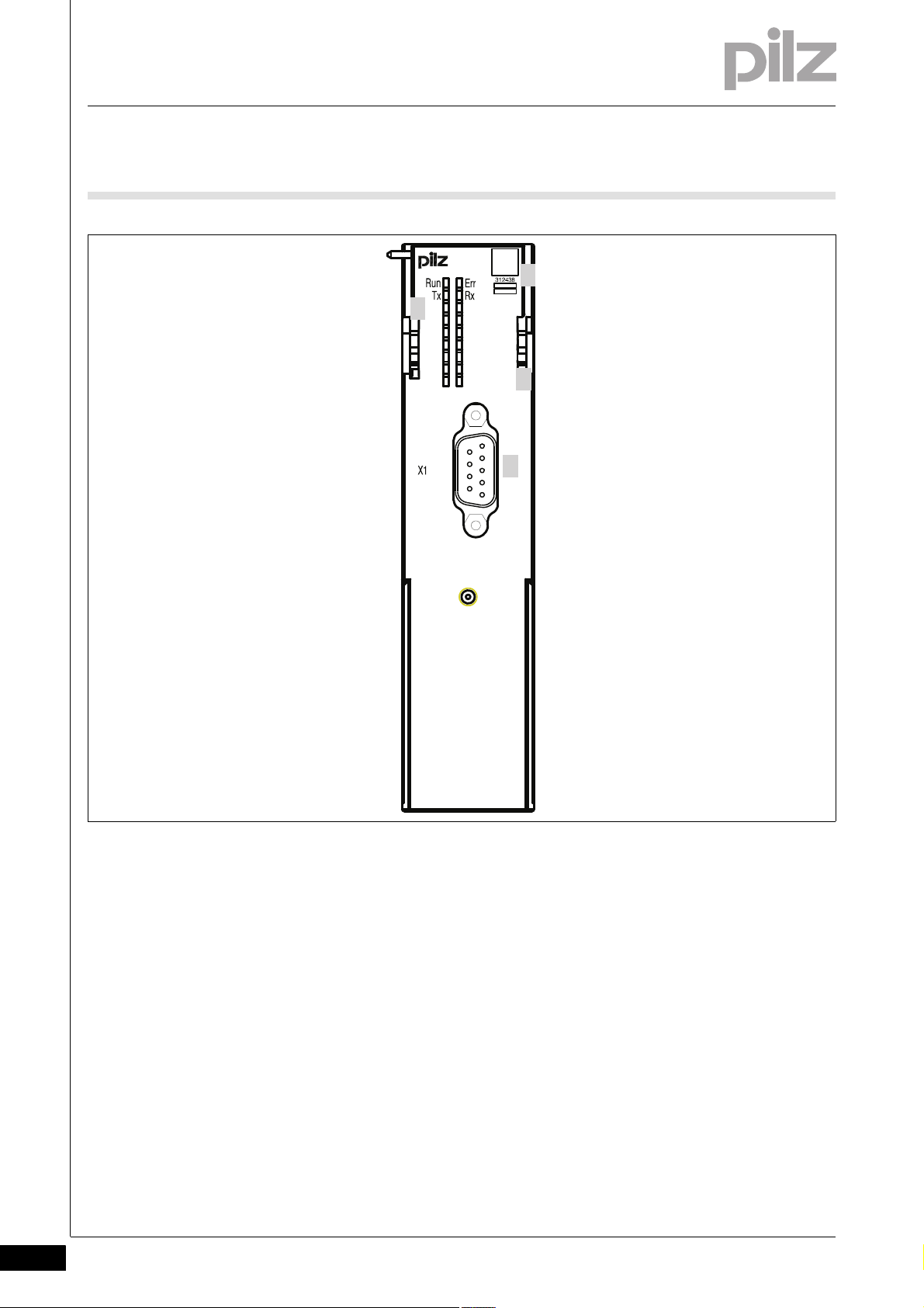
Key:
1: Labelling strip with:
–2D code
– Order Number
– Serial Number
– Hardware version number
2: Name of compact module
3: D-Sub connector (male) X1
4: LEDs for status display and module diagnostics
2-2
Pilz GmbH & Co. KG, Felix-Wankel-Straße 2, 73760 Ostfildern, Germany
Telephone: +49 711 3409-0, Telefax: +49 711 3409-133, E-Mail: pilz.gmbh@pilz.de
Page 11
3 Safety
3.1 Intended use
33000SafetySafety3-3.1Intended use3100Intended use3-][Gertebeschreibung ST Ser K Modul Trumph Sys B
Bestimmung/Gertebeschreibung_Ausschluss
Bestimm_Verwend_Info_PAS4000_ab_1.1.1
The module provides a serial interface. It is designed for communication
in non-safety-related applications in system environment B (automation
system PSS 4000).
Intended use includes making the electrical installation EMC-compliant.
Please refer to the guidelines stated in the "PSSuniversal Installation
Manual". The module is designed for use in an industrial environment. It
is not suitable for use in a domestic environment, as this can lead to interference.
The following is deemed improper use in particular:
Any component, technical or electrical modification to the module
Use of the module outside the areas described in this manual
Use of the module outside the technical details (see chapter entitled
"Technical Details")
INFORMATION
The module is supported by PAS4000 from Version 1.1.1. We
recommend that you always use the latest version (download
from www.pilz.de).
Pilz GmbH & Co. KG, Felix-Wankel-Straße 2, 73760 Ostfildern, Germany
Telephone: +49 711 3409-0, Telefax: +49 711 3409-133, E-Mail: pilz.gmbh@pilz.de
3-1
Page 12

3 Safety
3.2 Safety regulations
3.2Safety regulations3200Safety regulation s3-
3.2.1 Use of qualified personnel
Use of qualified personnel3-Sich Qualif. Personal
The products may only be assembled, installed, programmed, commissioned, operated, maintained and decommissioned by competent persons.
A competent person is someone who, because of their training, experience and current professional activity, has the specialist knowledge required to test, assess and operate the work equipment, devices,
systems, plant and machinery in accordance with the general standards
and guidelines for safety technology.
It is the company's responsibility only to employ personnel who:
Are familiar with the basic regulations concerning health and safety /
accident prevention
Have read and understood the safety guidelines given in this descrip-
tion
Have a good knowledge of the generic and specialist standards ap-
plicable to the specific application.
3.2.2 Warranty and liability
Warranty and liability3-Sich Gewhrleistung
3.2.3 Disposal
Disposal3-Si ch Entsorgung
All claims to warranty and liability will be rendered invalid if:
The product was used contrary to the purpose for which it is intended
Damage can be attributed to not having followed the guidelines in the
manual
Operating personnel are not suitably qualified
Any type of modification has been made (e.g. exchanging compo-
nents on the PCB boards, soldering work etc.).
In safety-related applications, please comply with the mission time t
M
in the safety-related characteristic data.
When decommissioning, please comply with local regulations regard-
ing the disposal of electronic devices (e.g. Electrical and Electronic
Equipment Act).
3-2
Pilz GmbH & Co. KG, Felix-Wankel-Straße 2, 73760 Ostfildern, Germany
Telephone: +49 711 3409-0, Telefax: +49 711 3409-133, E-Mail: pilz.gmbh@pilz.de
Page 13

4 Function description
Ext. device
with serial
interface
RS232
PSSu K S RS232
Modbus ASCII
Head
module
with
control
system
Module
bus
4.1 Module features
44000Function descriptionFunction description4-4.1Module features4100Module features4-
4.1.1 Function description
Function description4-][Funktionsbeschreibung BA Einleitung Ser
][Funktionsbeschreibung Module Supply
][Funktionsbeschreibung_Peri Ser
][Funktionsbeschreibung Datenaustausch Ser
][Funktionsdiagramm ST RS232 Modbus ASCII
The module enables communication via a serial interface.
Module supply
The module supply provides the module with voltage.
Periphery supply
The periphery supply provides the serial interface with voltage.
Signal processing
In each cycle, a max. of 8 Bytes of data can be transferred in both di-
rections between control system and module. The data to be transferred is stored temporarily in a send and receive buffer.
Two additional status bytes and control bytes are available in the
process image for data exchange between control system and module.
All the configuration data is stored in the head module and is assigned
to the module on restart. This way the configuration data is retained
even if you change the module.
Schematic representation of signal processing with the control system
PSSu PLC/PSSu multi:
4.1.2 Integrated protection mechanisms
Integrated protection mechanisms4-][Schutzmechanismen E/A-Module
When the PSSu E F PS1(-T) is used to supply the system, the module
supply is buffered for 20 ms if the supply voltage is interrupted.
][Schutzmechanismen ST-Module
The module detects the following errors:
Start-up error
Configuration error
ST communication error
Bus termination error
Pilz GmbH & Co. KG, Felix-Wankel-Straße 2, 73760 Ostfildern, Germany
Telephone: +49 711 3409-0, Telefax: +49 711 3409-133, E-Mail: pilz.gmbh@pilz.de
4-1
Page 14

4 Function description
4.2 Data exchange
4.2Data exchange4200Data exchange4-][Funktionsbeschreibung_Zusatz Ser
Data is exchanged between subscribers via a special protocol based on
the Modbus ASCII protocol.
INFORMATION
The necessary function block is available from Technical Support (telephone: +49 711 3409-444).
4-2
Pilz GmbH & Co. KG, Felix-Wankel-Straße 2, 73760 Ostfildern, Germany
Telephone: +49 711 3409-0, Telefax: +49 711 3409-133, E-Mail: pilz.gmbh@pilz.de
Page 15

4 Function description
4.3 Configuration
4.3Configuration4300Configuration4-][Funktionsbeschreibung_BA_Konfig Einf Ser
The module has the following configuration options:
Interface parameter
Threshold receive buffer
4.3.1 Interface parameters
Interface parameters4-][Funktionsbeschreibung_BA_Konfig K-Modul Trumph Ser
The following interface parameters can be configured:
Transmission rate
Xon/Xoff when sending
Xon/Xoff when receiving
RTS and CTS enabled
4.3.2 Receive buffer threshold
Receive buffer threshold 4-][Funktionsbeschrei bung_BA_Konfig Schwell Ser
The number of Bytes in a receive buffer of the module is defined with this
value, from which the status bit "Receive buffer full" is set (default value:
512).
Pilz GmbH & Co. KG, Felix-Wankel-Straße 2, 73760 Ostfildern, Germany
Telephone: +49 711 3409-0, Telefax: +49 711 3409-133, E-Mail: pilz.gmbh@pilz.de
4-3
Page 16

4 Function description
4-4
Pilz GmbH & Co. KG, Felix-Wankel-Straße 2, 73760 Ostfildern, Germany
Telephone: +49 711 3409-0, Telefax: +49 711 3409-133, E-Mail: pilz.gmbh@pilz.de
Page 17

5 Installation
49,2 mm
128,9 mm
5,07"
1,94"
30 mm
1,18"
5.1 General installation guidelines
55000InstallationInstallation5-5.1General installation guidelines5100General installation guidelines5-][Montage BA E-Modul Allgemein
Montage_EMV ESD
5.1.1 Dimensions
Dimensions5-][Abmessungen K-T rumph
Please also refer to the PSSuniversal Installation Manual.
CAUTION!
Damage due to electrostatic discharge!
Electrostatic discharge can damage components. Ensure
against discharge before touching the product, e.g. by touching
an earthed, conductive surface or by wearing an earthed armband.
Schematic representation:
Pilz GmbH & Co. KG, Felix-Wankel-Straße 2, 73760 Ostfildern, Germany
Telephone: +49 711 3409-0, Telefax: +49 711 3409-133, E-Mail: pilz.gmbh@pilz.de
5-1
Page 18
5 Installation
5.2 Install compact module
5.2Install compact module5200Install compact module5-][Montage Kompaktmodul Trumph
Prerequisite:
The head module must be installed.
If the head module does not have an integrated power supply, a sup-
ply voltage module must be installed to the right of the head module.
A base module with screw terminals may not be installed to the left of
the compact module.
Please note:
All contacts should be protected from contamination.
The mechanics of the compact modules are designed for 50 plug in/
out cycles.
Procedure:
Slot the groove on the compact module on to the mounting rail from
below [1].
Push the compact module back as far as it will go [2].
Make sure that the locking mechanism [3] is pushed downwards, con-
necting the module firmly to the mounting rail.
On the mounting rail, slide the compact module to the left.
NOTICE
Potential contact damage due to twisting!
The contacts for the Module Supply and Periphery Supply can
be bent by twisting the compact modules on the mounting rail.
On the mounting rail, carefully slide the compact module to the
left, in parallel to the adjoining module, until you hear the lateral
mounting hooks on the adjacent module lock into position [4].
5-2
Pilz GmbH & Co. KG, Felix-Wankel-Straße 2, 73760 Ostfildern, Germany
Telephone: +49 711 3409-0, Telefax: +49 711 3409-133, E-Mail: pilz.gmbh@pilz.de
Page 19

5 Installation
[1]
[3]
[4]
[2]
[4]
5.2 Install compact module
Schematic representation:
Pilz GmbH & Co. KG, Felix-Wankel-Straße 2, 73760 Ostfildern, Germany
Telephone: +49 711 3409-0, Telefax: +49 711 3409-133, E-Mail: pilz.gmbh@pilz.de
5-3
Page 20

5 Installation
5-4
Pilz GmbH & Co. KG, Felix-Wankel-Straße 2, 73760 Ostfildern, Germany
Telephone: +49 711 3409-0, Telefax: +49 711 3409-133, E-Mail: pilz.gmbh@pilz.de
Page 21

6 Wiring
1
5
6
9
6.1 Interface configuration
66000WiringWiring6-6.1Interface configuration6100Interface configuration6-
6.1.1 RS232 interface
RS232 interface6-][Schnittstelle RS232 K Trumph
RS 232 Layout X1
Male D-Sub connector 1: n.c.
2: Input Rx (receive data)
3: Output Tx (send data)
4: n.c.
5: GND
6: n.c.
7: Output RTS
8: Input CTS
9: n.c.
n.c. = not connected
Pilz GmbH & Co. KG, Felix-Wankel-Straße 2, 73760 Ostfildern, Germany
Telephone: +49 711 3409-0, Telefax: +49 711 3409-133, E-Mail: pilz.gmbh@pilz.de
6-1
Page 22

6 Wiring
6-2
Pilz GmbH & Co. KG, Felix-Wankel-Straße 2, 73760 Ostfildern, Germany
Telephone: +49 711 3409-0, Telefax: +49 711 3409-133, E-Mail: pilz.gmbh@pilz.de
Page 23

7 Operation
7.1 Messages
77000OperationOperation7-7.1Messages71 00Messages7-][BA_Betrie b Störung LED "Err" Sys B
A module error is displayed via the "Err" LED (see section entitled "Display elements"), signalled to the head module and then entered in the
][BA_Betrieb Fehler Ser
Errors Statement Remedy
Start-up error Error as the PSSu system starts up Change faulty module.
Configuration error Wrong module type selected or invalid
ST communication error Error during ST communication Change faulty module
Bus termination error There is no terminating plate or there is
head module's diagnostic log.
The module can detect the following errors:
Adjust the configured hardware regis-
module configuration
a bad contact with the module bus.
try to the actual hardware registry so
that they match, or correct the module
configuration.
Install a terminating plate with integrated end bracket or insert the base
modules together correctly.
Pilz GmbH & Co. KG, Felix-Wankel-Straße 2, 73760 Ostfildern, Germany
Telephone: +49 711 3409-0, Telefax: +49 711 3409-133, E-Mail: pilz.gmbh@pilz.de
7-1
Page 24

7 Operation
Run
Run
Err
Err
7.2 Display elements
7.2Display elements7200Display elements7-Anzeige Legende 2x
Key:
LED on
LED off
7.2.1 Display element for operational readiness
Display element for operational readiness7-BA_Anzeige
The module has an LED for displaying that the system is ready for operation (LED "Run").
LED Key
Description Colour Status
Run - - - Module not
7.2.2 Display element for module error
Display element for module error7-][BA_Anzeige LED Err K Trum ph
The module has an LED for displaying module errors ("Err" LED).
ready for operation
green Module ready
for operation
7-2
LED Key
Description Colour Status
Err - - - No fault
Red Module is faulty
Pilz GmbH & Co. KG, Felix-Wankel-Straße 2, 73760 Ostfildern, Germany
Telephone: +49 711 3409-0, Telefax: +49 711 3409-133, E-Mail: pilz.gmbh@pilz.de
Page 25
7 Operation
Rx
Tx
Tx
Rx
7.2 Display elements
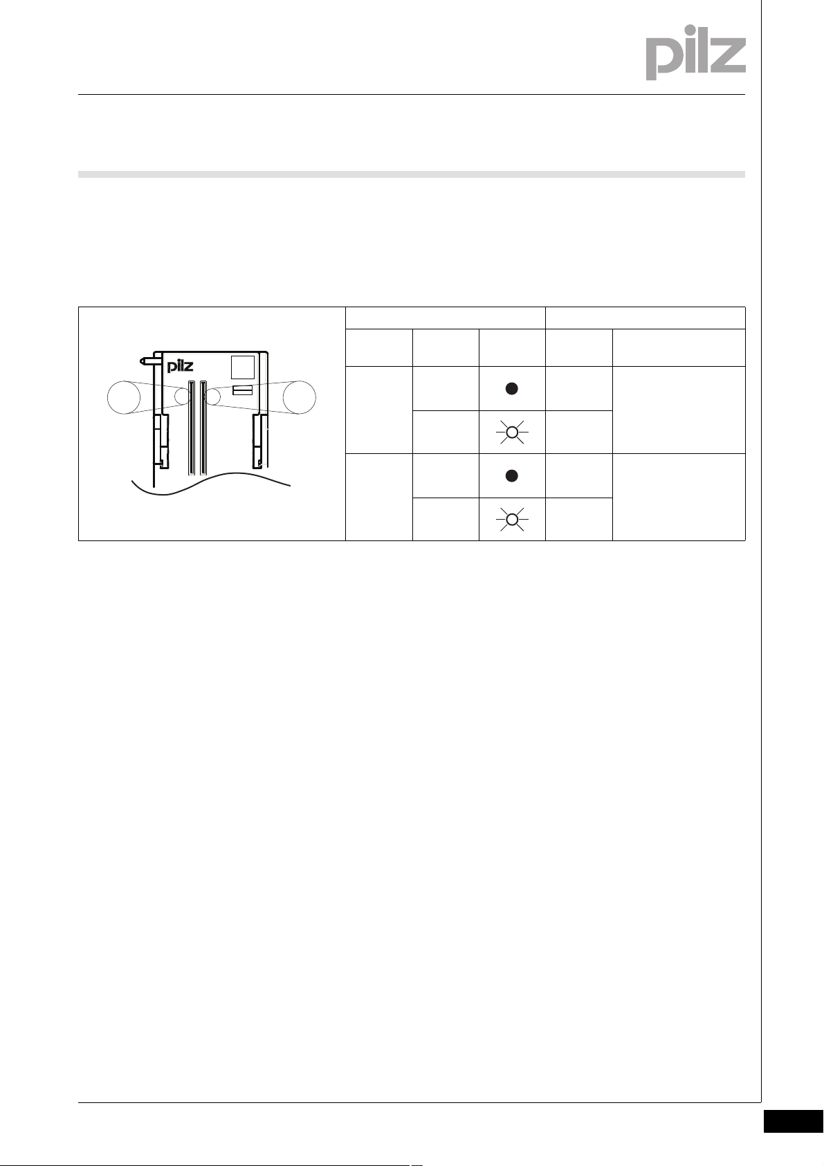
7.2.3 Display elements for data transmission
Display elements for data transmission7-BA_Anzeige
The module has the LEDs Tx and Rx for displaying the data transfer
(LEDs "Tx" and "Rx").
LED Key
Descrip-
tion
Tx - - - No data
Colour Status Signal Pin
green Send
2
transfer
data
Rx - - - No data
transfer
green Receive
data
3
Pilz GmbH & Co. KG, Felix-Wankel-Straße 2, 73760 Ostfildern, Germany
Telephone: +49 711 3409-0, Telefax: +49 711 3409-133, E-Mail: pilz.gmbh@pilz.de
7-3
Page 26

7 Operation
7-4
Pilz GmbH & Co. KG, Felix-Wankel-Straße 2, 73760 Ostfildern, Germany
Telephone: +49 711 3409-0, Telefax: +49 711 3409-133, E-Mail: pilz.gmbh@pilz.de
Page 27

8 Technical details
8.1 Technical details
88000Technical detailsTechnical details8-8.1Technical details8100Technical details8-][Technische Daten PSSu seriell(-T) Kompakt
Technical details
Application range Standard
Module's device code 0720h
Support in system environment A no
Support in system environment B yes
from head module ST firmware version 1.0.0
Electrical data
Internal supply voltage (module supply)
Supply voltage range of module supply 4.8 - 5.4 V
Module's current consumption 125 mA
Module's power consumption 0.63 W
Periphery's supply voltage (periphery supply)
Voltage range 16.8 - 30.0 V
Module's current consumption 20 mA
Module's power consumption 0.48 W
Max. power dissipation of the module 1.20 W
Serial interface
Number of RS232 interfaces 1
Transmission rate (configurable) 1.2 kBit/s, 19.2 kBit/s, 2.4 kBit/s, 300 Bit/s, 4.8 kBit/s,
600 Bit/s, 9.6 kBit/s
Max. cable run 15 m
Size of receive buffer 1,023 Byte
Size of send buffer 127 Byte
Potential isolation between interface and Module Supply yes
Potential isolation between interface and Periphery Supply yes
Environmental data
Climatic suitability EN 60068-2-14, EN 60068-2-1, EN 60068-2-2, EN 60068-
2-30, EN 60068-2-78
Ambient temperature in accordance with EN 60068-2-14 0 - 60 °C
Storage temperature in accordance with EN 60068-2-1/-2 -25 - 70 °C
Climatic suitability in accordance with EN 60068-2-30, EN
60068-2-78
Condensation not permitted
Max. operating height above sea level 2000 m
EMC EN 61000-4-2, EN 61000-4-3, EN 61000-4-4, EN 61000-
Vibration to EN 60068-2-6
Frequency 10.0 - 150.0 Hz
Max. acceleration 1g
Shock stress
EN 60068-2-27 15g
EN 60068-2-29 10g
Protection type in accordance with EN 60529
Mounting (e.g. cabinet) IP54
Housing IP20
Airgap creepage in accordance with EN 61131-2, IEC
60664-1
Overvoltage category II
Pollution degree 2
93 % r. h. at 40 °C
4-5, EN 61000-4-6, EN 61131-2
11 ms
16 ms
Pilz GmbH & Co. KG, Felix-Wankel-Straße 2, 73760 Ostfildern, Germany
Telephone: +49 711 3409-0, Telefax: +49 711 3409-133, E-Mail: pilz.gmbh@pilz.de
8-1
Page 28

8 Technical details
8.1 Technical details
Mechanical data
Housing material
Front PC
Bottom PC
Dimensions
Height 128.9 mm
Width 30.0 mm
Depth 56.0 mm
Weight 81 g
Technische Daten_Satz No rmen
The standards current on 2009-03 apply.
8-2
Pilz GmbH & Co. KG, Felix-Wankel-Straße 2, 73760 Ostfildern, Germany
Telephone: +49 711 3409-0, Telefax: +49 711 3409-133, E-Mail: pilz.gmbh@pilz.de
Page 29
8 Technical details
8.2 Order reference
8.2Order reference8200Order reference8-Best elldaten Mod ul
Order reference
Description Order no.
PSSu K S RS232 Modbus ASCII
(Compact module without connector, labelling bracket and labelling strips)
][Bestelldaten Zubehör K
Accessories Order no.
PSSu A Con 1/10 C, Scope of delivery: 2 pieces
(Connector with spring-loaded terminals, 1-row/10-pin)
PSSu A Con 3/30 C, Scope of delivery: 2 pieces
(Connector with spring-loaded terminals, 3-row/30-pin)
PSSu A LC 0.1, Scope of delivery: 5 pieces
(Labelling bracket)
PSSu A LA0, Scope of delivery: 1080 pieces (10 x DIN A4 sheet, 108 on each)
(Labelling strips, laser printable)
312 438
313 115
313 116
312 966
312 958
Pilz GmbH & Co. KG, Felix-Wankel-Straße 2, 73760 Ostfildern, Germany
Telephone: +49 711 3409-0, Telefax: +49 711 3409-133, E-Mail: pilz.gmbh@pilz.de
8-3
Page 30

8 Technical details
8-4
Pilz GmbH & Co. KG, Felix-Wankel-Straße 2, 73760 Ostfildern, Germany
Telephone: +49 711 3409-0, Telefax: +49 711 3409-133, E-Mail: pilz.gmbh@pilz.de
Page 31

...
1001689-EN-04, 2012-06 Printed in Germany
© Pilz GmbH & Co. KG, 2011
+49 711 3409-444
support@pilz.com
Pilz GmbH & Co. KG
Felix-Wankel-Straße 2
73760 Ostfildern, Germany
Telephone: +49 711 3409-0
Telefax: +49 711 3409-133
E-Mail: pilz.gmbh@pilz.de
Internet: www.pilz.com
Technical support
In many countries we are
represented by our subsidiaries
and sales partners.
Please refer to our homepage
for further details or contact our
headquarters.
InduraNET p
®
, Pilz
®
, PIT
®
, PMCprotego
®
, PMI
®
, PNOZ
®
, Primo
®
, PSEN
®
, PSS
®
, PVIS
®
, SafetyBUS p
®
, SafetyEYE
®
, SafetyNET p
®
, the spirit of safety
®
are registered and protected trademarks
of Pilz GmbH & Co. KG in some countries. We would point out that product features may vary from the details stated in this document, depending on the status at the time of publication and the scope
of the equipment. We accept no responsibility for the validity, accuracy and entirety of the text and graphics presented in this information. Please contact our Technical Support if you have any questions.
Contact address
 Loading...