

Page 1

Operating Manual PSSu H SB IBSe
Operating Manual PSSu H SB IBSe
PSSu H SB IBSe
Decentralised system PSSuniversal I/O
Operating Manual — No. 21709-EN-02
Page 2

This document is a translation of the original document.
All rights to this documentation are reserved by Pilz GmbH & Co. KG. Copies may be made
for internal purposes.
Suggestions and comments for improving this documentation will be gratefully received.
Pilz®, PIT®, PMI®, PNOZ®, Primo®, PSEN®, PSS®, PVIS®, SafetyBUS p®, SafetyEYE®,
SafetyNET p®, the spirit of safety® are registered and protected trademarks of
Pilz GmbH & Co. KG in some countries.
SD means Secure Digital.
Preface
Page 3

Contents
Contents
Contents Page
Chapter 1 Introduction
1.1 Validity of documentation 1-1
1.1.1 Retaining the documentation 1-1
1.2 Overview of documentation 1-2
1.3 Definition of symbols 1-3
Chapter 2 Overview
2.1 Module features 2-1
2.2 Front view 2-2
Chapter 3 Safety
3.1 Intended use 3-1
3.2 Safety regulations 3-3
3.2.1 Use of qualified personnel 3-3
3.2.2 Warranty and liability 3-3
3.2.3 Disposal 3-3
Chapter 4 Function description
4.1 Module features 4-1
4.1.1 Integrated protection mechanisms 4-1
4.1.2 Supply voltage 4-1
4.2 SafetyBUS p 4-2
4.2.1 Connection to SafetyBUS p 4-2
4.2.2 Selector switch for setting the device
address
4.3 INTERBUS 4-3
4.3.1 Connection to INTERBUS 4-3
4.3.2 Selector switch for setting the
transmission rate
4.3.3 Selector switch for setting the INTERBUS
parameters
4.4 USB port 4-5
Chapter 5 Installation
5.1 General installation guidelines 5-1
5.1.1 Dimensions 5-1
5.2 Installing the head module 5-2
Chapter 6 Interfaces
6.1 Interface assignment 6-1
6.1.1 Connection to SafetyBUS p 6-2
6.1.2 Connection to INTERBUS 6-2
6.1.3 Connection via USB 6-2
4-2
4-3
4-4
Pilz GmbH & Co. KG, Felix-Wankel-Straße 2, 73760 Ostfildern, Germany
Telephone: +49 711 3409-0, Telefax: +49 711 3409-133, E-Mail: pilz.gmbh@pilz.de
1
Page 4
Contents
Chapter 7 Operation
7.1 Messages 7-1
7.2 Display elements 7-3
7.2.1 Display elements for system diagnostics 7-3
7.2.2 Display elements for SafetyBUS p
7.2.3 Display elements for INTERBUS
7.3 Diagnostic bytes 7-8
7.3.1 Structure and contents of the status byte
7.3.2 Structure and contents of the slot byte
7.3.3 Structure and contents of the channel byte
7.3.4 Structure and contents of the module byte
7-5
diagnostics
7-6
diagnostics
7-8
(Byte 0)
7-8
(Byte 1)
7-8
(Byte 2)
7-9
(Byte 3)
Chapter 8 Technical details
8.1 Technical details 8-1
8.2 Order reference 8-3
Pilz GmbH & Co. KG, Felix-Wankel-Straße 2, 73760 Ostfildern, Germany
2
Telephone: +49 711 3409-0, Telefax: +49 711 3409-133, E-Mail: pilz.gmbh@pilz.de
Page 5

1 Introduction
1.1 Validity of documentation
11000IntroductionIntroduction1-1.1Validity of docume ntation1100Validity of documenta tion1-][BA Einf Gültigkeit Kopfmodul mit SB
This documentation is valid for the product PSSu H SB IBSe. It is valid
until new documentation is published.
Please also refer to the following documents:
SafetyBUS p System Description
SafetyBUS p Installation Manual
PSSuniversal System Description
Einf Einleitung
PSSuniversal Installation Manual
This operating manual explains the function and operation, describes
the installation and provides guidelines on how to connect the product .
1.1.1 Retaining the documentation
Retaining the documentation1-Einf Aufbewahren
This documentation is intended for instruction and should be retained
for future reference.
Pilz GmbH & Co. KG, Felix-Wankel-Straße 2, 73760 Ostfildern, Germany
Telephone: +49 711 3409-0, Telefax: +49 711 3409-133, E-Mail: pilz.gmbh@pilz.de
1-1
Page 6

1 Introduction
1.2 Overview of documentation
1.2Overview of documentation1200Overview of documentation1-][BA_Einführung Übersicht Kopfmodule
1 Introduction
The introduction is designed to familiarise you with the contents, structure and specific order of this manual.
2 Overview
This chapter provides information on the module's most important features.
3 Safety
This chapter must be read as it contains important information on safety
and intended use.
4 Function Description
This chapter describes the module's individual components.
5 Installation
This chapter explains how to install the module.
6 Interfaces
This chapter describes the module's interfaces.
7 Operation
This chapter explains the display elements and advises on what to do if
a fault occurs.
8 Technical Details
This chapter contains the product's technical details and order reference.
1-2
Pilz GmbH & Co. KG, Felix-Wankel-Straße 2, 73760 Ostfildern, Germany
Telephone: +49 711 3409-0, Telefax: +49 711 3409-133, E-Mail: pilz.gmbh@pilz.de
Page 7
1 Introduction
1.3 Definition of symbols
1.3Definition of symbols1300Definition of symbols1-Einfhrung Zeichen
Information that is particularly important is identified as follows:
DANGER!
This warning must be heeded! It warns of a hazardous situation
that poses an immediate threat of serious injury and death and
indicates preventive measures that can be taken.
WARNING!
This warning must be heeded! It warns of a hazardous situation
that could lead to serious injury and death and indicates preventive measures that can be taken.
CAUTION!
This refers to a hazard that can lead to a less serious or minor
injury plus material damage, and also provides information on
preventive measures that can be taken.
NOTICE
This describes a situation in which the unit(s) could be damaged
and also provides information on preventive measures that can
be taken. It also highlights areas within the text that are of particular importance.
INFORMATION
This gives advice on applications and provides information on
special features.
Pilz GmbH & Co. KG, Felix-Wankel-Straße 2, 73760 Ostfildern, Germany
Telephone: +49 711 3409-0, Telefax: +49 711 3409-133, E-Mail: pilz.gmbh@pilz.de
1-3
Page 8

1 Introduction
1-4
Pilz GmbH & Co. KG, Felix-Wankel-Straße 2, 73760 Ostfildern, Germany
Telephone: +49 711 3409-0, Telefax: +49 711 3409-133, E-Mail: pilz.gmbh@pilz.de
Page 9

2 Overview
2.1 Module features
22000OverviewOverview2-2.1Module features2100Module features2-Geraetemerkmale_Zusatz BA Einleitung
][Merkmale_Schnittstelle SB p und ST-Bus oZust
][Merkmale_LED SB p und ST-Bus
][Merkmale_E-Module SB p und ST-Bus
The product has the following features:
SafetyBUS p interface for
– Failsafe inputs/outputs
INTERBUS-Interface for
– Standard inputs/outputs
USB port for connection to a PC for
– Commissioning
– Service
LEDs for:
– System status
– SafetyBUS p status
–USB status
– Status of the INTERBUS interface
Electronic modules that can be used for input/output:
– All failsafe modules
(PSSu E F...)
– All standard modules
(PSSu E S...)
Pilz GmbH & Co. KG, Felix-Wankel-Straße 2, 73760 Ostfildern, Germany
Telephone: +49 711 3409-0, Telefax: +49 711 3409-133, E-Mail: pilz.gmbh@pilz.de
2-1
Page 10
2 Overview
PSSu H
SB IBSe
Usb Dev
SB I/O
SB ADDRESS
USB
2
D -
3
D +
5
G N D
USB
0
3
6
9
x 10
0
3
6
9
x 1
312 015
0000000
HW 000
000 000
RCRDUL
BA
ON
OFF
DIAG
FS IN
FS OUT
500k
2M
REMOTE OUTREMOTE IN
1
2
3
4
5
6
7
8
12
10
9
11
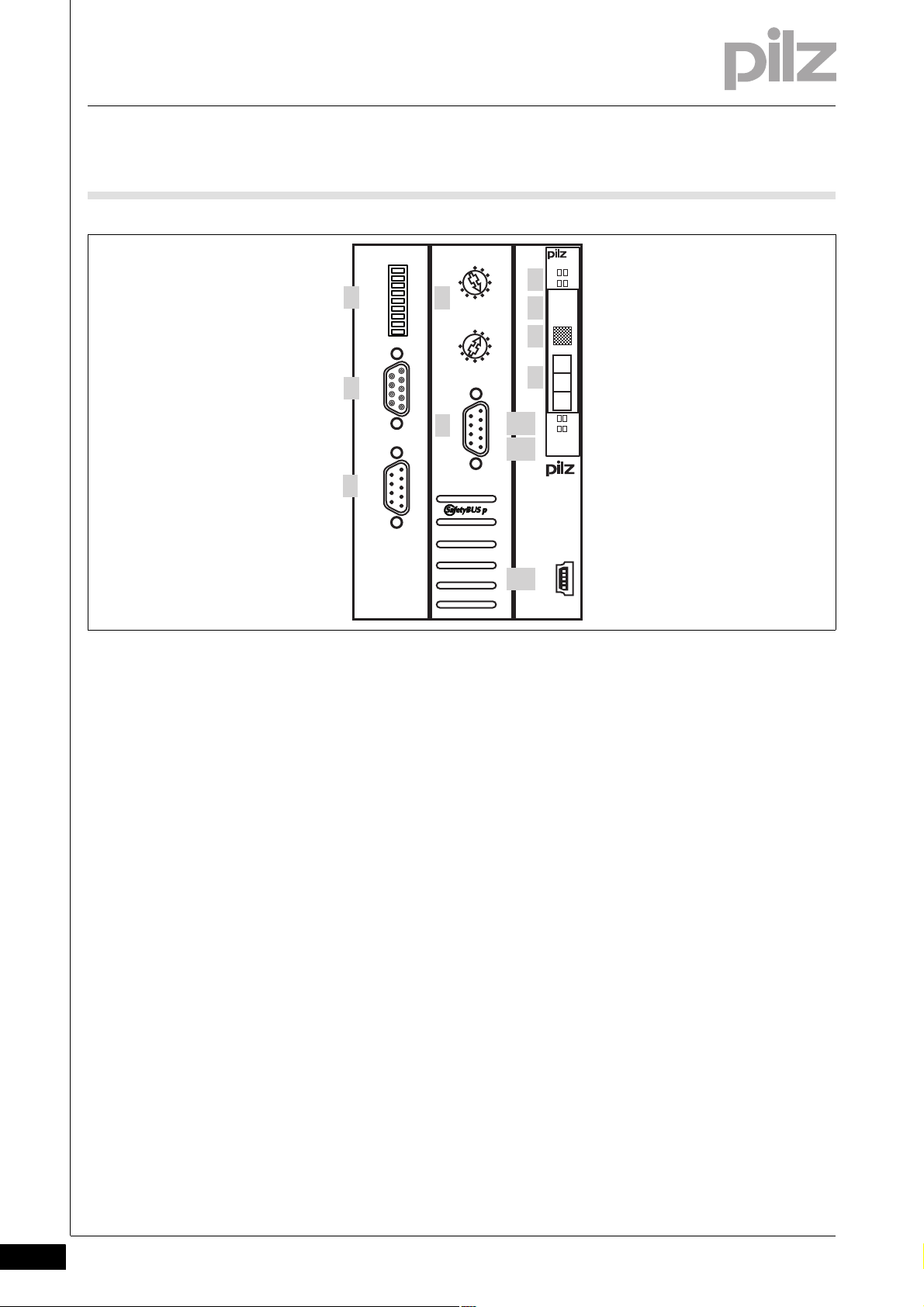
2.2 Front view
2.2Front view2200Front view2-BA_Fron tansicht
Key:
1: Selector switch for setting the transmission rate and other Interbus
parameters
2: Interbus interface for remote bus OUT
3: Interbus interface for remote bus IN
4: Two selector switches for setting the device address (SafetyBUS p)
5: SafetyBUS p interface
6: LEDs for system diagnostics and SafetyBUS p diagnostics
7: Labelling strip with:
– Order number
– Serial number
– Hardware version number
– Firmware version number on delivery
8: Field for 2D code
9: Labelling strip with interface configuration of the USB port
10: LEDs for Interbus diagnostics
11: Description of head module
12: USB port (Mini-B)
2-2
Pilz GmbH & Co. KG, Felix-Wankel-Straße 2, 73760 Ostfildern, Germany
Telephone: +49 711 3409-0, Telefax: +49 711 3409-133, E-Mail: pilz.gmbh@pilz.de
Page 11
3 Safety
3.1 Intended use
33000SafetySafety3-3.1Intended use3100Intended use3-][Bestimmu ng SB p und ST-Bus oZust
Bestimmung/Gertebeschreibung Kat./SIL_PSSu
Bestimmung/Gertebeschreibung_Ausschluss
The module is designed for use in:
Safety-related applications with
– SafetyBUS p
Non-safety-related applications with
– INTERBUS
The module meets the requirements of EN IEC 61508 up to SIL3 and
EN 954-1 up to Category 4.
Intended use includes making the electrical installation EMC-compliant.
Please refer to the guidelines stated in the "PSSuniversal Installation
Manual". The module is designed for use in an industrial environment. It
is not suitable for use in a domestic environment, as this can lead to interference.
Bestimm_Verwend_Info_PSSu_ab_1.4.0_Kopf FS50/18
BA_Bestimmung Ausschluss Zusatz Kopf - E-Modul
The following is deemed improper use in particular:
Any component, technical or electrical modification to the module
Use of the module outside the areas described in this manual
Use of the module outside the technical details (see chapter entitled
"Technical Details")
INFORMATION
The module is supported by the PSSuniversal Configurator and
PSSuniversal Assistant from Version 1.4.0. We recommend that
you always use the latest version (download from www.pilz.de).
The module is supported by programmable safety systems with
SafetyBUS p interface, from FS operating system version 50/18.
Programmable safety systems with an older FS operating system version will have a restricted function range.
Pilz GmbH & Co. KG, Felix-Wankel-Straße 2, 73760 Ostfildern, Germany
Telephone: +49 711 3409-0, Telefax: +49 711 3409-133, E-Mail: pilz.gmbh@pilz.de
3-1
Page 12
3 Safety
3.1 Intended use
The head module may be used in conjunction with the following elec-
][BA_Sicherheit E-Module FS /ST
Module type Module name
Voltage supply PSSu E F PS(-T)
Digital input/output modules PSSu E S 4DI(-T)
Analogue input/output modules PSSu E S 2AI I se(-T)
Counter modules PSSu E S ABS SSI(-T)
Voltage distribution PSSu E PD(-T)
][BA Bestimmung Firmware
tronic modules:
PSSu E F PS1(-T)
PSSu E F PS-P(-T)
PSSu E F BSW(-T)
PSSu E S 4DO 0.5(-T)
PSSu E S 2DO 2(-T)
PSSu E F 4DI(-T)
PSSu E F 4DO 0.5(-T)
PSSu E F 2DO 2(-T)
PSSu E F 2DOR 8(-T)
PSSu E F DI OZ 2(-T)
PSSu E S 4AI U(-T)
PSSu E S 2AI U(-T)
PSSu E S 2AO I(-T)
PSSu E S 4AO U(-T)
PSSu E S 2AO U(-T)
PSSu E S INC(-T)
PSSu E PD1(-T)
The module's firmware can be updated to a later version using the
Firmware Manager on the PSSuniversal Assistant. For the reason, the
module's actual firmware version may not always match the firmware
version printed on the front of the unit. Updating the firmware can also
expand the module's functionality.
INFORMATION
The module's actual firmware version can only be established
using the Firmware Manager on the PSSuniversal Assistant.
3-2
Pilz GmbH & Co. KG, Felix-Wankel-Straße 2, 73760 Ostfildern, Germany
Telephone: +49 711 3409-0, Telefax: +49 711 3409-133, E-Mail: pilz.gmbh@pilz.de
Page 13

3 Safety
3.2 Safety regulations
3.2Safety regulations3200Safety regulations3-
3.2.1 Use of qualified personnel
Use of qualified personnel3-Sich Qualif. Personal
The products may only be assembled, installed, programmed, commissioned, operated, maintained and decommissioned by competent persons.
A competent person is someone who, because of their training, experience and current professional activity, has the specialist knowledge required to test, assess and operate the work equipment, devices,
systems, plant and machinery in accordance with the general standards
and guidelines for safety technology.
It is the company's responsibility only to employ personnel who:
Are familiar with the basic regulations concerning health and safety /
accident prevention
Have read and understood the safety guidelines given in this descrip-
tion
Have a good knowledge of the generic and specialist standards ap-
plicable to the specific application.
3.2.2 Warranty and liability
Warranty and liability3-Sich Gewhrleistung
3.2.3 Disposal
Disposal3-Si ch Entsorgung
All claims to warranty and liability will be rendered invalid if:
The product was used contrary to the purpose for which it is intended
Damage can be attributed to not having followed the guidelines in the
manual
Operating personnel are not suitably qualified
Any type of modification has been made (e.g. exchanging compo-
nents on the PCB boards, soldering work etc.).
In safety-related applications, please comply with the mission time t
M
in the safety-related characteristic data.
When decommissioning, please comply with local regulations regard-
ing the disposal of electronic devices (e.g. Electrical and Electronic
Equipment Act).
Pilz GmbH & Co. KG, Felix-Wankel-Straße 2, 73760 Ostfildern, Germany
Telephone: +49 711 3409-0, Telefax: +49 711 3409-133, E-Mail: pilz.gmbh@pilz.de
3-3
Page 14

3 Safety
3-4
Pilz GmbH & Co. KG, Felix-Wankel-Straße 2, 73760 Ostfildern, Germany
Telephone: +49 711 3409-0, Telefax: +49 711 3409-133, E-Mail: pilz.gmbh@pilz.de
Page 15

4 Function description
4.1 Module features
44000Function descriptionFunction description4-4.1Module features4100Module features4-
4.1.1 Integrated protection mechanisms
Integrated protection mechanisms4-][Schutzmechanismen H SBUS + ST-BUS
The module has the following protection mechanisms:
Multi-channel diverse processor section
Cyclical self tests
Potentially isolated SafetyBUS p interface
Potentially isolated INTERBUS interface
When the PSSu E F PS1(-T) is used to supply the system, the module
supply is buffered for 20 ms if the supply voltage is interrupted.
4.1.2 Supply voltage
Supply voltage4-][Funktionsbeschreibung Module Supply
Module supply
The module supply provides the module with voltage.
Pilz GmbH & Co. KG, Felix-Wankel-Straße 2, 73760 Ostfildern, Germany
Telephone: +49 711 3409-0, Telefax: +49 711 3409-133, E-Mail: pilz.gmbh@pilz.de
4-1
Page 16

4 Function description
SB ADDRESS
0
3
6
9
x 10
0
3
6
9
x 1
4.2 SafetyBUS p
4.2SafetyBUS p4200SafetyBUS p4-
4.2.1 Connection to SafetyBUS p
Connection to SafetyBU S p4-][Funktion_BA_Zusatz SB p Kopplung
A PSSu with SafetyBUS p interface is regarded as a bus subscriber in a
SafetyBUS p network.
The “SafetyBUS p Installation Manual” and the “SafetyBUS p System
Description” apply for subscribers in a SafetyBUS p network.
Detailed descriptions for commissioning are available in the online help
for the PSS WIN-PRO system software. Step-by-step instructions can
be found in the manual: "Getting Started: Full version of PSS WIN-PRO".
4.2.2 Selector switch for setting the device address
Selector switch for setting the device address4-][Funktion_BA_Zusatz SB p Wahlschalter
The device address of a PSSu is set via the two rotary switches “x 10”
and “x 1”.
Permitted device addresses are in the range 32
plies if the PSSu system is configured for SafetyBUS p 1 in the Safety-
BUS p Configurator on the PSS WIN-PRO system software. The offset
of 100
for device addresses on SafetyBUS p 1 is calculated automati-
D
cally from the bus configuration.
Rotary switch “SB ADDRESS”:
Switch designation
x 10 Set the tens
x 1 Set the units
Key Example:
... 95D. The same ap-
D
Device address 51
D
4-2
Pilz GmbH & Co. KG, Felix-Wankel-Straße 2, 73760 Ostfildern, Germany
Telephone: +49 711 3409-0, Telefax: +49 711 3409-133, E-Mail: pilz.gmbh@pilz.de
Page 17

4 Function description
INTERBUS
Master
INTERBUS
Slave 1
PSSu
INTERBUS
Slave 2
INTERBUS
Slave n
PSSu H
SB IBSe
Usb Dev
SB I/O
USB
2
D 3
D +
5
G N D
USB
312 015
0000000
HW 000
000
RCRDUL
BA
ON
OFF
DIAG
FS 1
FS 0
500k 2M
REMOTE OUTREMOTE IN
OFF
ON
2M
DIAG
FS OUT
FS IN
500k
4.3 INTERBUS
4.3INTERBUS4300INTERBUS4-
4.3.1 Connection to INTERBUS
Connection to INTERBUS4-][ Funktionsbeschreibu ng_BA_Zusatz IBSe Kop plung
A PSSu system with INTERBUS interface is a passive subscriber (Slave)
of the INTERBUS remote bus without PCP channel.
4.3.2 Selector switch for setting the transmission rate
Selector switch for setting the transmission rate4-][Funktionsbeschreibung_BA_Zusatz IBS-FS bertragung
The INTERBUS transmission rate of a PSSu is set via the DIP switch labelled “500k” and “2M”.
Switch designation Position
off on
“500k”/“2M” 500 kBit/s 2 Mbit/s
DIAG Parameter
FS IN
FS OUT
- - Not assigned
INFORMATION
The INTERBUS transmission rate should only be set when the
module is switched off (no voltage applied).
The settings are only transferred when booting. Any changes
made to the settings during operation will not be transferred.
Pilz GmbH & Co. KG, Felix-Wankel-Straße 2, 73760 Ostfildern, Germany
Telephone: +49 711 3409-0, Telefax: +49 711 3409-133, E-Mail: pilz.gmbh@pilz.de
4-3
Page 18

4 Function description
OFF
ON
2M
DIAG
FS OUT
FS IN
500k
4.3 INTERBUS
4.3.3 Selector switch for setting the INTERBUS parameters
Selector switch for setting the INTERBUS parameters4-][Funktionsbeschreibung_BA_Zusatz IBS-FS Parameter
The INTERBUS parameters can be used to display diagnostic data and
FS section data in the ST-PII. These INTERBUS parameters are set via
the DIP switches labelled “DIAG”, “FS IN” and “FS OUT”.
The INTERBUS parameter “DIAG” determines whether the diagnostic
bytes are transferred. The four diagnostic bytes are displayed in the STPII.
INFORMATION
Further information on the structure and contents of the diagnostic byte can be found under “Operation”.
The INTERBUS parameters “FS IN” and “FS OUT” determine whether
the FS inputs and the switch status of the FS outputs on the PSSu system are transferred. The FS inputs and the status of the FS outputs are
displayed in the ST-PII. The FS inputs/outputs cannot be selected individually per module.
Switch designation Position
off on
“500k”/“2M” Transmission rate
DIAG Do not transfer
diagnostic bytes
FS IN Do not transfer
FS inputs
FS OUT Do not transfer
FS outputs
- - Not assigned
INFORMATION
INTERBUS parameters can be modified during operation. In the
ST-PII, the corresponding bits are added or hidden via the
switches “DIAG”, “FS IN” and “FS OUT”. As a result, the position of all the subsequent bits in the ST-PII may be shifted.
You can view the current process image in the PSSuniversal
Assistant.
Transfer diagnostic bytes
Transfer FS inputs
Transfer FS outputs
4-4
Pilz GmbH & Co. KG, Felix-Wankel-Straße 2, 73760 Ostfildern, Germany
Telephone: +49 711 3409-0, Telefax: +49 711 3409-133, E-Mail: pilz.gmbh@pilz.de
Page 19

4 Function description
4.4 USB port
4.4USB port4400USB port4-][Funktion_BA_Zusatz USB
The following functions are available via the USB port:
Show actual hardware
Comparison of actual/registered hardware
Display and update firmware versions
Setting the parameters for the ST section
Parameters for the module's ST section can either be set via the fieldbus
interface or via the USB port. Parameter setting via the USB port has priority over parameter setting via the fieldbus interface. Once parameters
for the the head module have been set via the USB port, the ability to set
parameters for the module via the fieldbus interface is disabled. The disable can be lifted in the PSSuniversal Assistant.
Procedure for connecting the head module via the USB port:
Connect PC to head module via USB cable.
Install USB driver.
View the actual hardware registry in the PSSuniversal Assistant and
call up other functions.
This way it is possible to copy and edit an existing configuration in the
PSSuniversal Assistant.
INFORMATION
The USB driver can be found on the PSSuniversal Assistant
CD-ROM, in the subdirectory \bin\PILZ_USB_DRIVER
Pilz GmbH & Co. KG, Felix-Wankel-Straße 2, 73760 Ostfildern, Germany
Telephone: +49 711 3409-0, Telefax: +49 711 3409-133, E-Mail: pilz.gmbh@pilz.de
4-5
Page 20

4 Function description
4-6
Pilz GmbH & Co. KG, Felix-Wankel-Straße 2, 73760 Ostfildern, Germany
Telephone: +49 711 3409-0, Telefax: +49 711 3409-133, E-Mail: pilz.gmbh@pilz.de
Page 21

5 Installation
56,4 mm
125,6 mm
72,6 mm
75,2 mm
69,2 mm
2,8 mm
21,6 mm
(2.448")(2.22")
(0.11")
(4.945")
(2.858")
(0.85")
(2.96")
5.1 General installation guidelines
55000InstallationInstallation5-5.1General installation guidelines5100General installation guidelines5-][Montage BA Kopfmodul Allgemein
Please also refer to the PSSuniversal Installation Manual.
The description below assumes that the mounting rail is already in-
Montage_EMV ESD
stalled.
CAUTION!
Damage due to electrostatic discharge!
Electrostatic discharge can damage components. Ensure
against discharge before touching the product, e.g. by touching
an earthed, conductive surface or by wearing an earthed armband.
5.1.1 Dimensions
Dimensions5-][Abmessungen SB p und ST-Bus
Pilz GmbH & Co. KG, Felix-Wankel-Straße 2, 73760 Ostfildern, Germany
Telephone: +49 711 3409-0, Telefax: +49 711 3409-133, E-Mail: pilz.gmbh@pilz.de
5-1
Page 22

5 Installation
[2]
[1]
5.2 Installing the head module
5.2Installing the head module5200Installing the head module5-][Montage Kopfmodul
Prerequisite:
The mounting rail must be installed.
Procedure:
Install an end bracket to the left of the head module or leave enough
space for one.
Slot the groove on the head module on to the mounting rail from be-
low [1].
Push the head module back [2] until you hear it lock into position.
Schematic representation:
5-2
Pilz GmbH & Co. KG, Felix-Wankel-Straße 2, 73760 Ostfildern, Germany
Telephone: +49 711 3409-0, Telefax: +49 711 3409-133, E-Mail: pilz.gmbh@pilz.de
Page 23

6 Interfaces
1
5
6
9
1
5
6
9
1
5
9
6
1
5
6.1 Interface assignment
66000InterfacesInterfaces6-6.1Interface assignment6100Interface assignment6-][Anschluss SB IBSe
SafetyBUS p Layout
Male 9-pin D-SUB connector 1: n.c.
2: CAN_L (brown)
3: CAN_GND (white)
4: n.c.
5: CAN_SHLD
6: n.c.
7: CAN_H (green)
8: Supply voltage for fibre-optic couplers from Pilz
9: n.c.
INTERBUS IBS IN Layout
Male 9-pin D-SUB connector conforms to the guidelines of the INTERBUS User Group
INTERBUS IBS OUT Layout
Female 9-pin D-SUB connector conforms to the guidelines of the INTERBUS User Group
USB Layout
Mini-B USB connector 1: n.c.
1: DO
2: DI
3: GND
4: GND
5: n.c.
6: DO7: DI8: + 5 V
9: n.c.
1: DO
2: DI
3: GND
4: GND
5: + 5 V
6: DO7: DI8: + 5 V
9: n.c.
2: D- USB Data –
3: D+ USB Data +
4: n.c.
5: GND Ground
n.c. = not connected
Pilz GmbH & Co. KG, Felix-Wankel-Straße 2, 73760 Ostfildern, Germany
Telephone: +49 711 3409-0, Telefax: +49 711 3409-133, E-Mail: pilz.gmbh@pilz.de
6-1
Page 24

6 Interfaces
6.1 Interface assignment
6.1.1 Connection to SafetyBUS p
Connection to SafetyBU S p6-][BA_Verdrah tung SB p
Please refer to the SafetyBUS p Installation Manual.
6.1.2 Connection to INTERBUS
Connection to INTERBUS6-][ BA_Verdrahtung IB Se
The connection to INTERBUS is made via a male 9-pin D-SUB connector "IBS-IN" and a female 9-pin D-SUB connector "IBS-OUT". Please refer to the guidelines issued by the INTERBUS Club.
The INTERBUS specification stipulates equipotential bonding between
the INTERBUS subscribers. Connect the screen from the incoming interface on the PSS ('IBS-IN') to the screen on the outgoing interface of
the INTERBUS subscriber immediately before it in the bus topology.
6.1.3 Connection via USB
Connection via USB6-][ BA_Verdrahtung USB
This equipotential bonding cable must have a cross section of at least
10 mm
2
. The equipotential bonding cable can also be connected to the
functional earth of the PSSu, e.g. via the C-rail.
Please note the requirements of the USB standard for USB 2.0 and for
Mini-B USB ports.
The maximum cable runs for USB connection cable are 5 m.
6-2
Pilz GmbH & Co. KG, Felix-Wankel-Straße 2, 73760 Ostfildern, Germany
Telephone: +49 711 3409-0, Telefax: +49 711 3409-133, E-Mail: pilz.gmbh@pilz.de
Page 25

7 Operation
7.1 Messages
77000OperationOperation7-7.1Messages71 00Messages7-][BA_ Betrieb Meldungen SB p
All errors and faults detected by the electronic modules on a PSSu are
signalled to the head module and entered in the head module's error
stack. You can read the head module's error stack using the
][BA_Betrieb Tabelle Meldungen FS+ST Sys A
Module error Statement Remedy
Start-up error Error as the PSSu system starts up Change faulty module
Configuration error Incorrect module type configured The configured hardware registry does
FS communication error Error during FS communication Change faulty module
ST communication error Error during ST communication Change faulty module
Bus termination error There is no terminating plate or there is
Temperature error: too warm (
Temperature error: too hot (1) Ambient temperature too high:
Output error Error during cyclical output test for
Test pulse error Possible causes: Short circuit be-
Relay control error Error during cyclical monitoring test of
Relay error A relay position is faulty;
Block switching output error Error during cyclical monitoring test of
Error in the feedback loop FS input detects an error in the feed-
Error in the local enable principle FS output has reacted incorrectly or
Input error Error during the cyclical input test;
Overload/short circuit Load on output too high Rectify overload or short circuit
1
) Ambient temperature too high:
PSS WIN-PRO system software (SafetyBUS p, Domain 0).
not match the actual hardware registry
Install a terminating plate with inte-
a bad contact with the module bus
Error stack entry
Reset the module and stop the affected I/O-Groups (SafetyBUS p)
short circuit. Possible causes: Short
circuit, or output defective
tween a test pulse and a supply voltage, or a defective module
the relay coils
possible cause: Defective relay contact
the relay contacts;
possible external cause: Voltages being fed back to the relay contacts
back loop or FS input is defective
unexpectedly
possible cause: Input defective
grated end bracket or insert the base
modules together correctly
Ensure there is sufficient ventilation in
the control cabinet or prevent overload
Ensure there is sufficient ventilation in
the control cabinet or prevent overload
Rectify the short circuit or change the
faulty module
Rectify the short circuit or change the
faulty module
Change faulty relay module
Change faulty relay module
Check the supply voltage and the wiring
Check FS input, check the configuration of the feedback loop, check the
signals, or check the wiring and contacts
Check the configuration of the FS output, or check the fieldbus signals in
the FS and ST section
Change faulty module
Pilz GmbH & Co. KG, Felix-Wankel-Straße 2, 73760 Ostfildern, Germany
Telephone: +49 711 3409-0, Telefax: +49 711 3409-133, E-Mail: pilz.gmbh@pilz.de
7-1
Page 26

7 Operation
7.1 Messages
Module error Statement Remedy
Overload of the supply voltage for encoder
Overvoltage error A system voltage or infeed is too high Stabilise the supply or change the
Undervoltage error A system voltage or infeed is too low Stabilise the supply or change the
Error in the overvoltage protection diodes
Timeout error on the output No data has been received for the out-
Polarity error Polarity of the periphery supply Correct the polarity
Error in the periphery supply Lower voltage limit exceeded on the
Supply voltage for encoder overloaded or short-circuited
Overvoltage protection diodes are defective
put from the module bus for longer
than 50 ms.
periphery supply
Rectify overload or short circuit
faulty supply voltage module
faulty supply voltage module
Change faulty supply voltage module
Check ST communication or configuration
Ensure there is a sufficient supply
(1) There are two levels of overtemperature.
Too warm:
If a module's temperature exceeds a threshold value, the module
sends a warning to the head module. If the temperature drops back
below the threshold value, the module sends an all-clear.
Too hot:
If a module's temperature exceeds a further threshold value, the module sends an error message to the head module and triggers an I/OGroup stop.
Further information on PSSu error messages is available in the online
help for the system software.
7-2
Pilz GmbH & Co. KG, Felix-Wankel-Straße 2, 73760 Ostfildern, Germany
Telephone: +49 711 3409-0, Telefax: +49 711 3409-133, E-Mail: pilz.gmbh@pilz.de
Page 27

7 Operation
Usb Dev
--- -- -
DevUsb
7.2 Display elements
7.2Display elements72 00Display elements7-Anzeige Legende 3x
Legend:
7.2.1 Display elements for system diagnostics
Display elements for system diagnostics7-][BA_Anzeige System
The module has LEDs to display various PSSu states (“Usb” LED and
“Dev” LED).
LED on
LED flashes
LED off
LED Key
Description Colour Status
Usb - - - No data is being
transmitted via
the USB port
Green Data is being
transmitted via
the USB port
Dev - - - PSSu system
error, no startup
Green PSSu running
without error
Red Error in the
head module
Red Error on the
module bus (*1)
1
) An error on the module bus (flashing red LED) may be due to one of
(*
the following reasons, which are stored in the error stack:
1. The head module cannot determine the registered hardware. Possible
causes:
Module bus is incomplete
Terminating resistor is missing.
A module is defective
Pilz GmbH & Co. KG, Felix-Wankel-Straße 2, 73760 Ostfildern, Germany
Telephone: +49 711 3409-0, Telefax: +49 711 3409-133, E-Mail: pilz.gmbh@pilz.de
A module does not have valid software.
Invalid hardware registry
Too many modules
7-3
Page 28

7 Operation
7.2 Display elements
Remedy: Correct the hardware registry.
2. Error: A module is missing. Possible cause:
The module has been removed.
The module has an error and is no longer registering after a reset.
The module has an error and switches to a system stop.
The module no longer has a voltage supply.
Remedy: Rectify the above points.
7-4
Pilz GmbH & Co. KG, Felix-Wankel-Straße 2, 73760 Ostfildern, Germany
Telephone: +49 711 3409-0, Telefax: +49 711 3409-133, E-Mail: pilz.gmbh@pilz.de
Page 29

7 Operation
SB ADDRESS
0
3
6
9
x 10
Usb Dev
SB I/O
I/OSB
7.2 Display elements
7.2.2 Display elements for SafetyBUS p diagnostics
Display elements for SafetyBUS p diagnostics7-][BA_ Anzeige SB p
The module has LEDs to display various SafetyBUS p states (“SB” LED
and “I/O” LED).
LED Key
Designation Colour
SB - - - No contact with
Green There is contact
I/O - - - All the SBp-De-
Green One of the SBp-
SafetyBUS p
(MD is not running or SBp wiring is faulty)
with
SafetyBUS p,
but the MD
does not recognise the SBpDevice. (faulty
device address
or SBp configuration)
Connection to
MD is running
correctly.
vice's I/OGroups are in a
STOP condition.
Device's I/OGroups is in a
STOP condition.
All the SBp-Device's I/OGroups are in a
RUN condition
Pilz GmbH & Co. KG, Felix-Wankel-Straße 2, 73760 Ostfildern, Germany
Telephone: +49 711 3409-0, Telefax: +49 711 3409-133, E-Mail: pilz.gmbh@pilz.de
7-5
Page 30

7 Operation
PSSu H
xx IBSe x
Usb Dev
SB I/O
SB ADDRESS
USB
2
D -
3
D +
5
G N D
USB
0
3
6
9
x 10
0
3
6
9
x 1
31...
0000000
HW 000
000 000
RCRDUL
BA
ON
OFF
DIAG
FS I
FS O
500k 2M
REMOTE OUTREMOTE IN
RCUL
7.2 Display elements
7.2.3 Display elements for INTERBUS diagnostics
Display elements for INTERBUS diagnostics7-][BA_Anzeige IBS Versorgung/Daten
The module has two LEDs to display the status of the supply (“RC” and
“UL” LED).
LED for INTERBUS diagnostics
Status of the supply
"UL" "RC"
Key
No supply voltage to the INTERBUS interface.
The INTERBUS interface is not
ready for operation.
The supply voltage to the INTERBUS interface is switched on.
The cable connection of the remote bus IN is defective or the Interbus master is in a reset
condition.
The supply voltage to the INTERBUS interface is switched on.
The INTERBUS interface is ready
for operation.
7-6
Pilz GmbH & Co. KG, Felix-Wankel-Straße 2, 73760 Ostfildern, Germany
Telephone: +49 711 3409-0, Telefax: +49 711 3409-133, E-Mail: pilz.gmbh@pilz.de
Page 31

7 Operation
PSSu H
xx IBSe x
Usb Dev
SB I/O
SB ADDRESS
USB
2
D -
3
D +
5
G N D
USB
0
3
6
9
x 10
0
3
6
9
x 1
31...
0000000
HW 000
000 000
RCRDUL
BA
ON
OFF
DIAG
FS I
FS O
500k 2M
REMOTE OUTREMOTE IN
RDBA
7.2 Display elements
The module has two LEDs to display the status of the data transfer (“RD”
and “BA” LED).
LED for INTERBUS diagnostics
Key
Status of the data transfer
Description Status
RD The remote bus OUT is switched
on.
The remote bus OUT is switched
off.
BA No data transfer
Data is being transmitted
Pilz GmbH & Co. KG, Felix-Wankel-Straße 2, 73760 Ostfildern, Germany
Telephone: +49 711 3409-0, Telefax: +49 711 3409-133, E-Mail: pilz.gmbh@pilz.de
7-7
Page 32

7 Operation
7.3 Diagnostic bytes
7.3Diagnostic bytes7300Diagnosti c bytes7-
7.3.1 Structure and contents of the status byte (Byte 0)
Structure and contents of the status byte (Byte 0)7-][BA_Betrieb ST-Bus Sta tus-Bytes
Bit number Signal Key
0 0 SafetyBUS p is not ready
1 SafetyBUS p is ready
1 0 SafetyBUS p input group is in a STOP condition.
1 SafetyBUS p input group is in a RUN condition.
2 0 SafetyBUS p output group is in a STOP condition.
1 SafetyBUS p output group is in a RUN condition.
3 0 No error in the PSSu FS section
1 Error in the PSSu FS section
4 0 No error in the PSSu ST section
1 Error in the PSSu ST section
5 Reserved
6 Reserved
7Not defined
7.3.2 Structure and contents of the slot byte (Byte 1)
Structure and contents of the slot byte (Byte 1)7-][BA_Betrieb ST-Bus Steck platz-Bytes
The slot byte (Byte 1) contains the slot number for the following diagnostic bytes (Byte 2/ Byte 3).
7.3.3 Structure and contents of the channel byte (Byte 2)
Structure and contents of the channel byte (Byte 2)7-][BA_Betrieb ST-Bus Kanal-Bytes
The channel byte (Byte 2) contains the following bits:
0 – 3: Channel number of the subsequent diagnostics
0xFF: Module diagnostics
7-8
Pilz GmbH & Co. KG, Felix-Wankel-Straße 2, 73760 Ostfildern, Germany
Telephone: +49 711 3409-0, Telefax: +49 711 3409-133, E-Mail: pilz.gmbh@pilz.de
Page 33

7 Operation
7.3 Diagnostic bytes
7.3.4 Structure and contents of the module byte (Byte 3)
Structure and contents of the module byte (Byte 3)7-][BA_Betrieb ST-Bus Modul-Bytes
Diagnostic value Description
0 No diagnostic value available
1 Short circuit
2 Undervoltage error (supply voltage modules)
3 Overvoltage error (supply voltage modules)
4 Overload
5 Temperature error: Too warm
6 Open circuit
7 Input value greater than limit value 2 (limit value monitoring, analogue modules)
8 Input value less than limit value 1 (limit value monitoring, analogue modules)
9 General module error
10 Reserved
11 Reserved
12 Reserved
13 Reserved
14 Reserved
15 Reserved
16 Protocol error
17 Error in the local enable principle (FS output modules)
18 Error in the parameter setup
19 Value below the lower limit value (range monitoring, analogue modules)
20 Value exceeds the upper limit value (range monitoring, analogue modules)
21 Configuration error
22-255 Not defined
Pilz GmbH & Co. KG, Felix-Wankel-Straße 2, 73760 Ostfildern, Germany
Telephone: +49 711 3409-0, Telefax: +49 711 3409-133, E-Mail: pilz.gmbh@pilz.de
7-9
Page 34

7 Operation
7-10
Pilz GmbH & Co. KG, Felix-Wankel-Straße 2, 73760 Ostfildern, Germany
Telephone: +49 711 3409-0, Telefax: +49 711 3409-133, E-Mail: pilz.gmbh@pilz.de
Page 35

8 Technical details
8.1 Technical details
88000Technical detailsTechnical details8-8.1Technical details8100Technical details8-][Technische Daten PSSu Kopf SBUS+ST-BUS oZust
Technical details
Application range Standard/Failsafe
Maximum achievable category in accordance with
EN 954-1
Maximum achievable SIL value SIL3
Module's device code 0223h
Electrical data
Internal supply voltage
Supply voltage range of module supply 4.9 - 5.1 V
Current and power consumption from module supply
Module's current consumption without FO connection 620 mA
FO connection's current consumption 120 mA
Module's power consumption without FO connection 3.10 W
FO connection's power consumption 0.60 W
Max. power dissipation of the module 3.10 W
Potential isolation between module supply and
INTERBUS
Potential isolation between module supply and
SafetyBUS p
SafetyBUS p
Application range Failsafe applications
Device address 32d ... 95d
Max. transmission rate 500 kBit/s
Cable runs 3,500 m
Transmission type differential two-wire cable
Connection Male 9-pin D-SUB connector
INTERBUS
Application range Standard applications
Device type Slave
Maximum data length of the fieldbus interface: Input 64 Byte
Maximum data length of the fieldbus interface: Output 64 Byte
Maximum data length of the fieldbus interface: Diagnostics 4 Byte
Transmission rates 2 MBit/s, 500 kBit/s
Set via DIP switch
Connection Male 9-pin D-SUB connector/female 9-pin D-SUB con-
Protocol INTERBUS-Protokoll
Operating modes Slave Mode
Manufacturer's ID 248h
USB
Connection Mini-B connector
Environmental data
Climatic suitability EN 60068-2-14, EN 60068-2-1, EN 60068-2-2,
Ambient temperature 0 - 60 °C
Storage temperature -25 - 70 °C
Climatic suitability in accordance with EN 60068-2-78 93 % r. h. at 40 °C
Condensation no
EMC EN 61000-4-2, EN 61000-4-3, EN 61000-4-4,
4
700 V
700 V
nector
EN 60068-2-30, EN 60068-2-78
EN 61000-4-5, EN 61000-4-6, EN 61000-6-2,
EN 61000-6-4
Pilz GmbH & Co. KG, Felix-Wankel-Straße 2, 73760 Ostfildern, Germany
Telephone: +49 711 3409-0, Telefax: +49 711 3409-133, E-Mail: pilz.gmbh@pilz.de
8-1
Page 36

8 Technical details
8.1 Technical details
Environmental data
Vibration to EN 60068-2-6
Frequency 10 - 150 Hz
Max. acceleration 1g
Shock stress
EN 60068-2-27 15g
11 ms
EN 60068-2-29 10g
16 ms
Protection type
Mounting (e.g. cabinet) IP54
Housing IP20
Airgap creepage in accordance with EN 60664-1
Overvoltage category II
Pollution degree 2
Mechanical data
Housing material
Front PC
Bottom PC
Dimensions
Height 128.4 mm
Width 75.2 mm
Depth 79.4 mm
Weight 170 g
SI-Kennzahlen_PSSu_Kop f
Safety characteristic data
Unit Operating mode
EN ISO 13849-1PLEN 954-1
Category
EN IEC 62061
SIL CL PFH [1/h] tM [year]
Logic --- PL e (Cat. 4) Cat. 4 SIL CL 3 2.88E-09 20
Si_Kennzahlen_Erläuterung
All the units used within a safety function must be considered when cal-
Technische Daten_Satz No rmen
culating the safety characteristic data.
8-2
Pilz GmbH & Co. KG, Felix-Wankel-Straße 2, 73760 Ostfildern, Germany
Telephone: +49 711 3409-0, Telefax: +49 711 3409-133, E-Mail: pilz.gmbh@pilz.de
Page 37

8 Technical details
8.2 Order reference
8.2Order reference8200Order reference8-Bestelldaten
Order reference
Description Order no.
PSSu H SB IBSe
(Head module with SafetyBUS p interface and INTERBUS
interface via copper cable)
312 015
Pilz GmbH & Co. KG, Felix-Wankel-Straße 2, 73760 Ostfildern, Germany
Telephone: +49 711 3409-0, Telefax: +49 711 3409-133, E-Mail: pilz.gmbh@pilz.de
8-3
Page 38

8 Technical details
8-4
Pilz GmbH & Co. KG, Felix-Wankel-Straße 2, 73760 Ostfildern, Germany
Telephone: +49 711 3409-0, Telefax: +49 711 3409-133, E-Mail: pilz.gmbh@pilz.de
Page 39

...
21709-EN-02, 2011-06 Printed in Germany
© Pilz GmbH & Co. KG, 2011
+49 711 3409-444
support@pilz.com
Pilz GmbH & Co. KG
Felix-Wankel-Straße 2
73760 Ostfildern, Germany
Telephone: +49 711 3409-0
Telefax: +49 711 3409-133
E-Mail: pilz.gmbh@pilz.de
Internet: www.pilz.com
Technical support
In many countries we are
represented by our subsidiaries
and sales partners.
Please refer to our homepage
for further details or contact our
headquarters.
InduraNET p
®
, Pilz
®
, PIT
®
, PMCprotego
®
, PMI
®
, PNOZ
®
, Primo
®
, PSEN
®
, PSS
®
, PVIS
®
, SafetyBUS p
®
, SafetyEYE
®
, SafetyNET p
®
, the spirit of safety
®
are registered and protected trademarks
of Pilz GmbH & Co. KG in some countries. We would point out that product features may vary from the details stated in this document, depending on the status at the time of publication and the scope
of the equipment. We accept no responsibility for the validity, accuracy and entirety of the text and graphics presented in this information. Please contact our Technical Support if you have any questions.
Contact address
 Loading...