

Page 1

Operating Manual PSSu H SB CAN(-T)
Operating Manual PSSu H SB CAN(-T)
PSSu H SB CAN(-T)
Decentralised system PSSuniversal I/O
Operating Manual — No. 21459-EN-02
Page 2

This document is a translation of the original document.
All rights to this documentation are reserved by Pilz GmbH & Co. KG. Copies may be made
for internal purposes.
Suggestions and comments for improving this documentation will be gratefully received.
Pilz®, PIT®, PMI®, PNOZ®, Primo®, PSEN®, PSS®, PVIS®, SafetyBUS p®, SafetyEYE®,
SafetyNET p®, the spirit of safety® are registered and protected trademarks of
Pilz GmbH & Co. KG in some countries.
SD means Secure Digital.
Preface
Page 3

Contents
Contents
Contents Page
Chapter 1 Introduction
1.1 Validity of documentation 1-1
1.1.1 Retaining the documentation 1-1
1.2 Overview of documentation 1-2
1.3 Definition of symbols 1-3
Chapter 2 Overview
2.1 Module features 2-1
2.2 Front view 2-2
Chapter 3 Safety
3.1 Intended use 3-1
3.2 Safety regulations 3-3
3.2.1 Use of qualified personnel 3-3
3.2.2 Warranty and liability 3-3
3.2.3 Disposal 3-3
Chapter 4 Function description
4.1 Module features 4-1
4.1.1 Integrated protection mechanisms 4-1
4.1.2 Supply voltage 4-1
4.2 SafetyBUS p 4-2
4.2.1 Connection to SafetyBUS p 4-2
4.2.2 Selector switch for setting the device
address
4.3 CANopen 4-3
4.3.1 Connection to CANopen 4-3
4.3.2 Selector switch for setting the
transmission rate
4.3.3 Selector switch for setting the station
address
4.4 USB port 4-6
Chapter 5 Installation
5.1 General installation guidelines 5-1
5.1.1 Dimensions 5-1
5.2 Installing the head module 5-2
Chapter 6 Interfaces
6.1 Interface configuration 6-1
6.1.1 Connection to SafetyBUS p 6-1
6.1.2 Connection to CANopen 6-1
6.1.3 Connection via USB 6-2
4-2
4-4
4-5
Pilz GmbH & Co. KG, Felix-Wankel-Straße 2, 73760 Ostfildern, Germany
Telephone: +49 711 3409-0, Telefax: +49 711 3409-133, E-Mail: pilz.gmbh@pilz.de
1
Page 4

Contents
Chapter 7 Operation
7.1 Messages 7-1
7.2 Display elements 7-3
7.2.1 Display elements for system diagnostics 7-3
7.2.2 Display elements for SafetyBUS p
7.2.3 Display elements for CANopen diagnostics 7-6
7.3 CANopen object description 7-9
7.3.1 Communication profile 7-9
7.3.2 Device profile 7-10
7.3.3 Manufacturer-specific objects 7-11
7.3.4 Object overview 7-13
7-5
diagnostics
Chapter 8 Technical details
8.1 Technical details 8-1
8.2 Order reference 8-3
Pilz GmbH & Co. KG, Felix-Wankel-Straße 2, 73760 Ostfildern, Germany
2
Telephone: +49 711 3409-0, Telefax: +49 711 3409-133, E-Mail: pilz.gmbh@pilz.de
Page 5

1 Introduction
1.1 Validity of documentation
11000IntroductionIntroduction1-1.1Validity of docume ntation1100Validity of documenta tion1-][BA Einf Gültigkeit Kopfmodul mit SB mit T-Variante
This documentation is valid for the product PSSu H SB CAN and
PSSu H SB CAN-T. It is valid until new documentation is published.
Please also refer to the following documents:
SafetyBUS p System Description
SafetyBUS p Installation Manual
PSSuniversal System Description
Einf Einleitung
PSSuniversal Installation Manual
This operating manual explains the function and operation, describes
the installation and provides guidelines on how to connect the product .
1.1.1 Retaining the documentation
Retaining the documentation1-Einf Aufbewahren
This documentation is intended for instruction and should be retained
for future reference.
Pilz GmbH & Co. KG, Felix-Wankel-Straße 2, 73760 Ostfildern, Germany
Telephone: +49 711 3409-0, Telefax: +49 711 3409-133, E-Mail: pilz.gmbh@pilz.de
1-1
Page 6

1 Introduction
1.2 Overview of documentation
1.2Overview of documentation1200Overview of documentation1-][BA_Einführung Übersicht Kopfmodule
1 Introduction
The introduction is designed to familiarise you with the contents, structure and specific order of this manual.
2 Overview
This chapter provides information on the module's most important features.
3 Safety
This chapter must be read as it contains important information on safety
and intended use.
4 Function Description
This chapter describes the module's individual components.
5 Installation
This chapter explains how to install the module.
6 Interfaces
This chapter describes the module's interfaces.
7 Operation
This chapter explains the display elements and advises on what to do if
a fault occurs.
8 Technical Details
This chapter contains the product's technical details and order reference.
1-2
Pilz GmbH & Co. KG, Felix-Wankel-Straße 2, 73760 Ostfildern, Germany
Telephone: +49 711 3409-0, Telefax: +49 711 3409-133, E-Mail: pilz.gmbh@pilz.de
Page 7
1 Introduction
1.3 Definition of symbols
1.3Definition of symbols1300Definition of symbols1-Einfhrung Zeichen
Information that is particularly important is identified as follows:
DANGER!
This warning must be heeded! It warns of a hazardous situation
that poses an immediate threat of serious injury and death and
indicates preventive measures that can be taken.
WARNING!
This warning must be heeded! It warns of a hazardous situation
that could lead to serious injury and death and indicates preventive measures that can be taken.
CAUTION!
This refers to a hazard that can lead to a less serious or minor
injury plus material damage, and also provides information on
preventive measures that can be taken.
NOTICE
This describes a situation in which the unit(s) could be damaged
and also provides information on preventive measures that can
be taken. It also highlights areas within the text that are of particular importance.
INFORMATION
This gives advice on applications and provides information on
special features.
Pilz GmbH & Co. KG, Felix-Wankel-Straße 2, 73760 Ostfildern, Germany
Telephone: +49 711 3409-0, Telefax: +49 711 3409-133, E-Mail: pilz.gmbh@pilz.de
1-3
Page 8

1 Introduction
1-4
Pilz GmbH & Co. KG, Felix-Wankel-Straße 2, 73760 Ostfildern, Germany
Telephone: +49 711 3409-0, Telefax: +49 711 3409-133, E-Mail: pilz.gmbh@pilz.de
Page 9

2 Overview
2.1 Module features
22000OverviewOverview2-2.1Module features2100Module features2-Geraetemerkmale_Zusatz BA Einleitung
][Merkmale_Schnittstelle SB p und ST-Bus
][Merkmale_LED SB p und ST-Bus
][Merkmale_E-Module SB p und ST-Bus
][Geraetemerkmal_T
The product has the following features:
SafetyBUS p interface for
– Failsafe inputs/outputs
CANopen interface for
– Standard inputs/outputs
– Failsafe outputs with the local enable principle
USB port for connection to a PC for
– Commissioning
– Service
LEDs for:
– System status
– SafetyBUS p status
–USB status
– Status of the CANopen interface
Electronic modules that can be used for input/output:
– All failsafe modules
(PSSu E F...)
– All standard modules
(PSSu E S...)
Coated version of the module:
PSSu H SB CAN-T: for increased environmental requirements
Pilz GmbH & Co. KG, Felix-Wankel-Straße 2, 73760 Ostfildern, Germany
Telephone: +49 711 3409-0, Telefax: +49 711 3409-133, E-Mail: pilz.gmbh@pilz.de
2-1
Page 10
2 Overview
CANopen
PSSu H
SB CAN
Usb Dev
SB I/O
SB ADDRESS
USB
2
D -
3
D +
5
G N D
USB
0
3
6
9
x 10
0
3
6
9
x 1
312 035
0000000
HW 000
000 000
ADDRESS
OFF
ON
S1
64
32
16
8
4
2
1
S2
S2
BAUD
AUTO
OFF
500K
OFF
250K
OFF
ON
S1 OFF ONONON
BAUD
125K
Run
Err
1
2
3
4
5
6
7
8
12
10
9
11
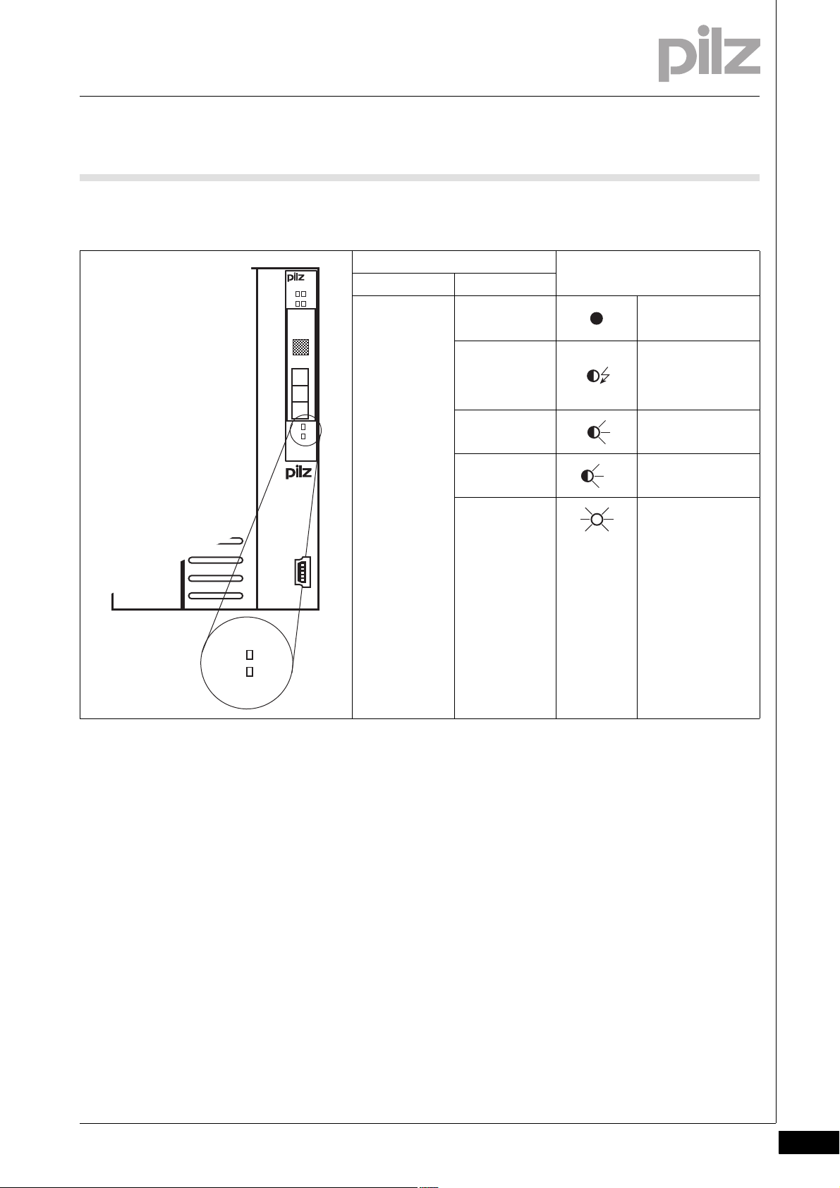
2.2 Front view
2.2Front view2200Front view2-BA_Fron tansicht
Key:
1: Selector switch for setting the station address and transmission
rate (CANopen)
2: Labelling strip with guidelines for setting the transmission rate
(CANopen)
3: CANopen interface
4: Two selector switches for setting the device address (SafetyBUS p)
5: SafetyBUS p interface
6: LEDs for system diagnostics and SafetyBUS p diagnostics
7: Labelling strip with:
– Order number
– Serial number
– Hardware version number
– Firmware version number on delivery
8: Field for 2D code
9: Labelling strip with interface configuration of the USB port
10: LEDs for CANopen diagnostics
11: Description of head module
12: USB port (Mini-B)
2-2
Pilz GmbH & Co. KG, Felix-Wankel-Straße 2, 73760 Ostfildern, Germany
Telephone: +49 711 3409-0, Telefax: +49 711 3409-133, E-Mail: pilz.gmbh@pilz.de
Page 11

3 Safety
3.1 Intended use
33000SafetySafety3-3.1Intended use3100Intended use3-][Bestimmu ng SB p und ST-Bus mZust
Bestimm_Verwend_ Zusatz-(T)
Bestimmung/Gertebeschreibung Kat./SIL_PSSu
Bestimmung/Gertebeschreibung_Ausschluss
The module is designed for use in:
Safety-related applications with
– SafetyBUS p
– CANopen With local enable principle
Non-safety-related applications with
–CANopen
The module PSSu H SB CAN-T is suitable for use where there are increased environmental requirements (see Technical Details).
The module meets the requirements of EN IEC 61508 up to SIL3 and
EN 954-1 up to Category 4.
Bestimm_Verwend_Info_PSSu_ab_1.4.0_Kopf FS50/18
BA_Bestimmung Ausschluss Zusatz Kopf - E-Modul
Intended use includes making the electrical installation EMC-compliant.
Please refer to the guidelines stated in the "PSSuniversal Installation
Manual". The module is designed for use in an industrial environment. It
is not suitable for use in a domestic environment, as this can lead to interference.
The following is deemed improper use in particular:
Any component, technical or electrical modification to the module
Use of the module outside the areas described in this manual
Use of the module outside the technical details (see chapter entitled
"Technical Details")
INFORMATION
The module is supported by the PSSuniversal Configurator and
PSSuniversal Assistant from Version 1.4.0. We recommend that
you always use the latest version (download from www.pilz.de).
The module is supported by programmable safety systems with
SafetyBUS p interface, from FS operating system version 50/18.
Programmable safety systems with an older FS operating system version will have a restricted function range.
Pilz GmbH & Co. KG, Felix-Wankel-Straße 2, 73760 Ostfildern, Germany
Telephone: +49 711 3409-0, Telefax: +49 711 3409-133, E-Mail: pilz.gmbh@pilz.de
3-1
Page 12

3 Safety
3.1 Intended use
The head module may be used in conjunction with the following elec-
][BA_Sicherheit E-Module FS /ST
Module type Module name
Voltage supply PSSu E F PS(-T)
Digital input/output modules PSSu E S 4DI(-T)
Analogue input/output modules PSSu E S 2AI I se(-T)
Counter modules PSSu E S ABS SSI(-T)
Voltage distribution PSSu E PD(-T)
][BA Bestimmung Firmware
tronic modules:
PSSu E F PS1(-T)
PSSu E F PS-P(-T)
PSSu E F BSW(-T)
PSSu E S 4DO 0.5(-T)
PSSu E S 2DO 2(-T)
PSSu E F 4DI(-T)
PSSu E F 4DO 0.5(-T)
PSSu E F 2DO 2(-T)
PSSu E F 2DOR 8(-T)
PSSu E F DI OZ 2(-T)
PSSu E S 4AI U(-T)
PSSu E S 2AI U(-T)
PSSu E S 2AO I(-T)
PSSu E S 4AO U(-T)
PSSu E S 2AO U(-T)
PSSu E S INC(-T)
PSSu E PD1(-T)
The module's firmware can be updated to a later version using the
Firmware Manager on the PSSuniversal Assistant. For the reason, the
module's actual firmware version may not always match the firmware
version printed on the front of the unit. Updating the firmware can also
expand the module's functionality.
INFORMATION
The module's actual firmware version can only be established
using the Firmware Manager on the PSSuniversal Assistant.
3-2
Pilz GmbH & Co. KG, Felix-Wankel-Straße 2, 73760 Ostfildern, Germany
Telephone: +49 711 3409-0, Telefax: +49 711 3409-133, E-Mail: pilz.gmbh@pilz.de
Page 13

3 Safety
3.2 Safety regulations
3.2Safety regulations3200Safety regulations3-
3.2.1 Use of qualified personnel
Use of qualified personnel3-Sich Qualif. Personal
The products may only be assembled, installed, programmed, commissioned, operated, maintained and decommissioned by competent persons.
A competent person is someone who, because of their training, experience and current professional activity, has the specialist knowledge required to test, assess and operate the work equipment, devices,
systems, plant and machinery in accordance with the general standards
and guidelines for safety technology.
It is the company's responsibility only to employ personnel who:
Are familiar with the basic regulations concerning health and safety /
accident prevention
Have read and understood the safety guidelines given in this descrip-
tion
Have a good knowledge of the generic and specialist standards ap-
plicable to the specific application.
3.2.2 Warranty and liability
Warranty and liability3-Sich Gewhrleistung
3.2.3 Disposal
Disposal3-Si ch Entsorgung
All claims to warranty and liability will be rendered invalid if:
The product was used contrary to the purpose for which it is intended
Damage can be attributed to not having followed the guidelines in the
manual
Operating personnel are not suitably qualified
Any type of modification has been made (e.g. exchanging compo-
nents on the PCB boards, soldering work etc.).
In safety-related applications, please comply with the mission time t
M
in the safety-related characteristic data.
When decommissioning, please comply with local regulations regard-
ing the disposal of electronic devices (e.g. Electrical and Electronic
Equipment Act).
Pilz GmbH & Co. KG, Felix-Wankel-Straße 2, 73760 Ostfildern, Germany
Telephone: +49 711 3409-0, Telefax: +49 711 3409-133, E-Mail: pilz.gmbh@pilz.de
3-3
Page 14

3 Safety
3-4
Pilz GmbH & Co. KG, Felix-Wankel-Straße 2, 73760 Ostfildern, Germany
Telephone: +49 711 3409-0, Telefax: +49 711 3409-133, E-Mail: pilz.gmbh@pilz.de
Page 15

4 Function description
4.1 Module features
44000Function descriptionFunction description4-4.1Module features4100Module features4-
4.1.1 Integrated protection mechanisms
Integrated protection mechanisms4-][Schutzmechanismen H SBUS + ST-BUS
The module has the following protection mechanisms:
Multi-channel diverse processor section
Cyclical self tests
Potentially isolated SafetyBUS p interface
Potentially isolated CANopen interface
When the PSSu E F PS1(-T) is used to supply the system, the module
supply is buffered for 20 ms if the supply voltage is interrupted.
4.1.2 Supply voltage
Supply voltage4-][Funktionsbeschreibung Module Supply
Module supply
The module supply provides the module with voltage.
Pilz GmbH & Co. KG, Felix-Wankel-Straße 2, 73760 Ostfildern, Germany
Telephone: +49 711 3409-0, Telefax: +49 711 3409-133, E-Mail: pilz.gmbh@pilz.de
4-1
Page 16

4 Function description
SB ADDRESS
0
3
6
9
x 10
0
3
6
9
x 1
4.2 SafetyBUS p
4.2SafetyBUS p4200SafetyBUS p4-
4.2.1 Connection to SafetyBUS p
Connection to SafetyBU S p4-][Funktion_BA_Zusatz SB p Kopplung
A PSSu with SafetyBUS p interface is regarded as a bus subscriber in a
SafetyBUS p network.
The “SafetyBUS p Installation Manual” and the “SafetyBUS p System
Description” apply for subscribers in a SafetyBUS p network.
Detailed descriptions for commissioning are available in the online help
for the PSS WIN-PRO system software. Step-by-step instructions can
be found in the manual: "Getting Started: Full version of PSS WIN-PRO".
4.2.2 Selector switch for setting the device address
Selector switch for setting the device address4-][Funktion_BA_Zusatz SB p Wahlschalter
The device address of a PSSu is set via the two rotary switches “x 10”
and “x 1”.
Permitted device addresses are in the range 32
plies if the PSSu system is configured for SafetyBUS p 1 in the Safety-
BUS p Configurator on the PSS WIN-PRO system software. The offset
of 100
for device addresses on SafetyBUS p 1 is calculated automati-
D
cally from the bus configuration.
Rotary switch “SB ADDRESS”:
Switch designation
x 10 Set the tens
x 1 Set the units
Key Example:
... 95D. The same ap-
D
Device address 51
D
4-2
Pilz GmbH & Co. KG, Felix-Wankel-Straße 2, 73760 Ostfildern, Germany
Telephone: +49 711 3409-0, Telefax: +49 711 3409-133, E-Mail: pilz.gmbh@pilz.de
Page 17

4 Function description
CANopen
Master
CANopen
Slave 1
PSSu
CANopen
Slave 2
CANopen
Slave n
4.3 CANopen
4.3CANopen4300CANopen4-
4.3.1 Connection to CANopen
Connection to CANopen4-][Funktionsbeschreibung_BA_Zusatz CAN Kopplung
A PSSu system with CANopen interface is a passive subscriber (Slave)
of the CANopen fieldbus.
The basic communication functions with CANopen conform to CiA DS301 V3.0. The central controller (Master) reads input information from
the slaves and writes output information to the slaves as part of each
cycle.
Bus termination must be activated on both ends of the bus.
Pilz GmbH & Co. KG, Felix-Wankel-Straße 2, 73760 Ostfildern, Germany
Telephone: +49 711 3409-0, Telefax: +49 711 3409-133, E-Mail: pilz.gmbh@pilz.de
4-3
Page 18
4 Function description
ADDRESS
OFF
ON
S2
S1
32
16
8
4
2
1
BAUD
64
4.3 CANopen
4.3.2 Selector switch for setting the transmission rate
Selector switch for setting the transmission rate4-][Funktionsbeschreibung_BA_Zusatz CAN Übertragung
The transmission rate of a PSSu is set via the “BAUD” DIP switches S1
and S2.
“BAUD” DIP switch Key Example:
Switch designation AUTO 500
KBit/s
S2 OFF OFF ON ON
S1 OFF ON OFF ON
64
32
16
8
4
2
1
Station address
250
kBit/s
125
kBit/s
Transmission rate
500 kBit/s
INFORMATION
The transmission rate should only be set when the module is
switched off (no voltage applied).
The settings are only transferred when booting. Any changes
made to the settings during operation will not be transferred.
If the PSSu station has lots of telegrams to send via the CANopen fieldbus, make sure that the transmission rate is high enough, e.g. when several analogue input/output modules are used. If the transmission rate is
too low, the PSSu may not be able to establish a connection to the
CANopen fieldbus.
4-4
Pilz GmbH & Co. KG, Felix-Wankel-Straße 2, 73760 Ostfildern, Germany
Telephone: +49 711 3409-0, Telefax: +49 711 3409-133, E-Mail: pilz.gmbh@pilz.de
Page 19

4 Function description
ADDRESS
OFF
ON
S2
S1
32
16
8
4
2
1
BAUD
64
4.3 CANopen
4.3.3 Selector switch for setting the station address
Selector switch for setting the station address4-][Funktionsbeschreibung_BA_Zusatz CAN Station
The station address of a PSSu (“Node ID”) is set via the “ADDRESS” DIP
switches (“1”, “2”, “4”, “8”, “16”, “32” and “64”). The DIP switches are
binary coded. Permitted station addresses are in the range 0
A station address is set via a combination of the relevant binary coded
switches:
“ADDRESS” DIP switch Key Example
Switch designation OFF ON Station address 116
S2 Transmission rate
S1
64 0 64
32 0 32
16 0 16
808
404
202
101
D
D
D
D
D
D
D
... 127D.
D
D
INFORMATION
The station address should only be set when the module is
switched off (no voltage applied).
The settings are only transferred when booting. Any changes
made to the settings during operation will not be transferred.
Each station address on a CANopen network must be unique.
Pilz GmbH & Co. KG, Felix-Wankel-Straße 2, 73760 Ostfildern, Germany
Telephone: +49 711 3409-0, Telefax: +49 711 3409-133, E-Mail: pilz.gmbh@pilz.de
4-5
Page 20

4 Function description
4.4 USB port
4.4USB port4400USB port4-][Funktion_BA_Zusatz USB
The following functions are available via the USB port:
Show actual hardware
Comparison of actual/registered hardware
Display and update firmware versions
Setting the parameters for the ST section
Parameters for the module's ST section can either be set via the fieldbus
interface or via the USB port. Parameter setting via the USB port has priority over parameter setting via the fieldbus interface. Once parameters
for the the head module have been set via the USB port, the ability to set
parameters for the module via the fieldbus interface is disabled. The disable can be lifted in the PSSuniversal Assistant.
Procedure for connecting the head module via the USB port:
Connect PC to head module via USB cable.
Install USB driver.
View the actual hardware registry in the PSSuniversal Assistant and
call up other functions.
This way it is possible to copy and edit an existing configuration in the
PSSuniversal Assistant.
INFORMATION
The USB driver can be found on the PSSuniversal Assistant
CD-ROM, in the subdirectory \bin\PILZ_USB_DRIVER
4-6
Pilz GmbH & Co. KG, Felix-Wankel-Straße 2, 73760 Ostfildern, Germany
Telephone: +49 711 3409-0, Telefax: +49 711 3409-133, E-Mail: pilz.gmbh@pilz.de
Page 21

5 Installation
56,4 mm
125,6 mm
72,6 mm
75,2 mm
69,2 mm
2,8 mm
21,6 mm
(2.448")(2.22")
(0.11")
(4.945")
(2.858")
(0.85")
(2.96")
5.1 General installation guidelines
55000InstallationInstallation5-5.1General installation guidelines5100General installation guidelines5-][Montage BA Kopfmodul Allgemein
Please also refer to the PSSuniversal Installation Manual.
The description below assumes that the mounting rail is already in-
Montage_EMV ESD
stalled.
CAUTION!
Damage due to electrostatic discharge!
Electrostatic discharge can damage components. Ensure
against discharge before touching the product, e.g. by touching
an earthed, conductive surface or by wearing an earthed armband.
5.1.1 Dimensions
Dimensions5-][Abmessungen SB p und ST-Bus
Pilz GmbH & Co. KG, Felix-Wankel-Straße 2, 73760 Ostfildern, Germany
Telephone: +49 711 3409-0, Telefax: +49 711 3409-133, E-Mail: pilz.gmbh@pilz.de
5-1
Page 22

5 Installation
[2]
[1]
5.2 Installing the head module
5.2Installing the head module5200Installing the head module5-][Montage Kopfmodul
Prerequisite:
The mounting rail must be installed.
Procedure:
Install an end bracket to the left of the head module or leave enough
space for one.
Slot the groove on the head module on to the mounting rail from be-
low [1].
Push the head module back [2] until you hear it lock into position.
Schematic representation:
5-2
Pilz GmbH & Co. KG, Felix-Wankel-Straße 2, 73760 Ostfildern, Germany
Telephone: +49 711 3409-0, Telefax: +49 711 3409-133, E-Mail: pilz.gmbh@pilz.de
Page 23

6 Interfaces
1
5
6
9
1
5
6
9
1
5
6.1 Interface configuration
66000InterfacesInterfaces6-6.1Interface configuration6100Interface configuration6-][A nschluss SB CAN
SafetyBUS p Layout
Male 9-pin D-SUB connector 1: n.c.
2: CAN_L (brown)
3: CAN_GND (white)
4: n.c.
5: CAN_SHLD
6: n.c.
7: CAN_H (green)
8: Supply voltage for fibre-optic couplers from Pilz
9: n.c.
CANopen Layout
Male 9-pin D-SUB connector 1: n.c.
2: CAN_L
3: CAN_GND
4: n.c.
5: CAN_SHLD
6: GND
7: CAN_H
8: n.c.
9: n.c.
USB Layout
Mini-B USB connector 1: n.c.
2: D- USB Data –
3: D+ USB Data +
4: n.c.
5: GND Ground
n.c. = not connected
(1)
(1)
Not required for operation
6.1.1 Connection to SafetyBUS p
Connection to SafetyBU S p6-][BA_Verdrah tung SB p
Please refer to the SafetyBUS p Installation Manual.
6.1.2 Connection to CANopen
Connection to CANopen6-][BA_Ve rdrahtung CAN
The connection cable must conform to the requirements of CiA DS 102
V2.0.
Only shielded cable should be used as the CANopen connection cable.
Connect the cable shield on the CANopen connection cable to Pin 5 of
the 9-pin D-Sub connector. The relationship of the cable runs to the bit
rate must be maintained.
Pilz GmbH & Co. KG, Felix-Wankel-Straße 2, 73760 Ostfildern, Germany
Telephone: +49 711 3409-0, Telefax: +49 711 3409-133, E-Mail: pilz.gmbh@pilz.de
6-1
Page 24

6 Interfaces
6.1 Interface configuration
6.1.3 Connection via USB
Connection via USB6-][ BA_Verdrahtung USB
Please note the requirements of the USB standard for USB 2.0 and for
Mini-B USB ports.
The maximum cable runs for USB connection cable are 5 m.
6-2
Pilz GmbH & Co. KG, Felix-Wankel-Straße 2, 73760 Ostfildern, Germany
Telephone: +49 711 3409-0, Telefax: +49 711 3409-133, E-Mail: pilz.gmbh@pilz.de
Page 25

7 Operation
7.1 Messages
77000OperationOperation7-7.1Messages71 00Messages7-][BA_ Betrieb Meldungen SB p
All errors and faults detected by the electronic modules on a PSSu are
signalled to the head module and entered in the head module's error
stack. You can read the head module's error stack using the
][BA_Betrieb Tabelle Meldungen FS+ST Sys A
Module error Statement Remedy
Start-up error Error as the PSSu system starts up Change faulty module
Configuration error Incorrect module type configured The configured hardware registry does
FS communication error Error during FS communication Change faulty module
ST communication error Error during ST communication Change faulty module
Bus termination error There is no terminating plate or there is
Temperature error: too warm (
Temperature error: too hot (1) Ambient temperature too high:
Output error Error during cyclical output test for
Test pulse error Possible causes: Short circuit be-
Relay control error Error during cyclical monitoring test of
Relay error A relay position is faulty;
Block switching output error Error during cyclical monitoring test of
Error in the feedback loop FS input detects an error in the feed-
Error in the local enable principle FS output has reacted incorrectly or
Input error Error during the cyclical input test;
Overload/short circuit Load on output too high Rectify overload or short circuit
1
) Ambient temperature too high:
PSS WIN-PRO system software (SafetyBUS p, Domain 0).
not match the actual hardware registry
Install a terminating plate with inte-
a bad contact with the module bus
Error stack entry
Reset the module and stop the affected I/O-Groups (SafetyBUS p)
short circuit. Possible causes: Short
circuit, or output defective
tween a test pulse and a supply voltage, or a defective module
the relay coils
possible cause: Defective relay contact
the relay contacts;
possible external cause: Voltages being fed back to the relay contacts
back loop or FS input is defective
unexpectedly
possible cause: Input defective
grated end bracket or insert the base
modules together correctly
Ensure there is sufficient ventilation in
the control cabinet or prevent overload
Ensure there is sufficient ventilation in
the control cabinet or prevent overload
Rectify the short circuit or change the
faulty module
Rectify the short circuit or change the
faulty module
Change faulty relay module
Change faulty relay module
Check the supply voltage and the wiring
Check FS input, check the configuration of the feedback loop, check the
signals, or check the wiring and contacts
Check the configuration of the FS output, or check the fieldbus signals in
the FS and ST section
Change faulty module
Pilz GmbH & Co. KG, Felix-Wankel-Straße 2, 73760 Ostfildern, Germany
Telephone: +49 711 3409-0, Telefax: +49 711 3409-133, E-Mail: pilz.gmbh@pilz.de
7-1
Page 26
7 Operation
7.1 Messages
Module error Statement Remedy
Overload of the supply voltage for encoder
Overvoltage error A system voltage or infeed is too high Stabilise the supply or change the
Undervoltage error A system voltage or infeed is too low Stabilise the supply or change the
Error in the overvoltage protection diodes
Timeout error on the output No data has been received for the out-
Polarity error Polarity of the periphery supply Correct the polarity
Error in the periphery supply Lower voltage limit exceeded on the
Supply voltage for encoder overloaded or short-circuited
Overvoltage protection diodes are defective
put from the module bus for longer
than 50 ms.
periphery supply
Rectify overload or short circuit
faulty supply voltage module
faulty supply voltage module
Change faulty supply voltage module
Check ST communication or configuration
Ensure there is a sufficient supply
(1) There are two levels of overtemperature.
Too warm:
If a module's temperature exceeds a threshold value, the module
sends a warning to the head module. If the temperature drops back
below the threshold value, the module sends an all-clear.
Too hot:
If a module's temperature exceeds a further threshold value, the module sends an error message to the head module and triggers an I/OGroup stop.
Further information on PSSu error messages is available in the online
help for the system software.
7-2
Pilz GmbH & Co. KG, Felix-Wankel-Straße 2, 73760 Ostfildern, Germany
Telephone: +49 711 3409-0, Telefax: +49 711 3409-133, E-Mail: pilz.gmbh@pilz.de
Page 27

7 Operation
Usb Dev
--- - --
DevUsb
7.2 Display elements
7.2Display elements72 00Display elements7-Anzeige Legende 3x
Legend:
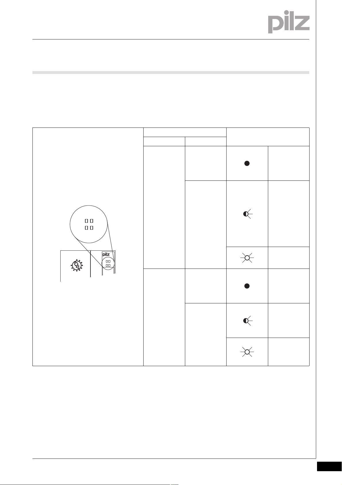
7.2.1 Display elements for system diagnostics
Display elements for system diagnostics7-][BA_Anzeige System
The module has LEDs to display various PSSu states (“Usb” LED and
“Dev” LED).
LED on
LED flashes
LED off
LED Key
Description Colour Status
Usb - - - No data is being
transmitted via
the USB port
Green Data is being
transmitted via
the USB port
Dev - - - PSSu system
error, no startup
Green PSSu running
without error
Red Error in the
head module
Red Error on the
module bus (*1)
1
) An error on the module bus (flashing red LED) may be due to one of
(*
the following reasons, which are stored in the error stack:
1. The head module cannot determine the registered hardware. Possible
causes:
Module bus is incomplete
Terminating resistor is missing.
A module is defective
Pilz GmbH & Co. KG, Felix-Wankel-Straße 2, 73760 Ostfildern, Germany
Telephone: +49 711 3409-0, Telefax: +49 711 3409-133, E-Mail: pilz.gmbh@pilz.de
A module does not have valid software.
Invalid hardware registry
Too many modules
7-3
Page 28

7 Operation
7.2 Display elements
Remedy: Correct the hardware registry.
2. Error: A module is missing. Possible cause:
The module has been removed.
The module has an error and is no longer registering after a reset.
The module has an error and switches to a system stop.
The module no longer has a voltage supply.
Remedy: Rectify the above points.
7-4
Pilz GmbH & Co. KG, Felix-Wankel-Straße 2, 73760 Ostfildern, Germany
Telephone: +49 711 3409-0, Telefax: +49 711 3409-133, E-Mail: pilz.gmbh@pilz.de
Page 29
7 Operation
SB ADDRESS
0
3
6
9
x 10
Usb Dev
SB I/O
I/OSB
7.2 Display elements
7.2.2 Display elements for SafetyBUS p diagnostics
Display elements for SafetyBUS p diagnostics7-][BA_ Anzeige SB p
The module has LEDs to display various SafetyBUS p states (“SB” LED
and “I/O” LED).
LED Key
Designation Colour
SB - - - No contact with
Green There is contact
I/O - - - All the SBp-De-
Green One of the SBp-
SafetyBUS p
(MD is not running or SBp wiring is faulty)
with
SafetyBUS p,
but the MD
does not recognise the SBpDevice. (faulty
device address
or SBp configuration)
Connection to
MD is running
correctly.
vice's I/OGroups are in a
STOP condition.
Device's I/OGroups is in a
STOP condition.
All the SBp-Device's I/OGroups are in a
RUN condition
Pilz GmbH & Co. KG, Felix-Wankel-Straße 2, 73760 Ostfildern, Germany
Telephone: +49 711 3409-0, Telefax: +49 711 3409-133, E-Mail: pilz.gmbh@pilz.de
7-5
Page 30

7 Operation
1
2
3
4
7.2 Display elements
7.2.3 Display elements for CANopen diagnostics
Display elements for CANopen diagnostics7-][BA_Anzeige CAN
The module has LEDs to display various CANopen states (“Run” LED
and “Err” LED).
Key:
LED off Permanently off
LED flashes once 50 ms on, 50 ms off
LED flashes once 200 ms on, 1000 ms off
LED flashes twice On twice for 200 ms, off for 200 ms in between, then off for 1000 ms
LED flashes three times On three times for 200 ms, off for 200 ms in between, then off for 1000 ms
LED flashes four times On four times for 200 ms, off for 200 ms in between, then off for 1000 ms
LED flashes 200 ms on, 200 ms off
LED on Permanently on
7-6
Pilz GmbH & Co. KG, Felix-Wankel-Straße 2, 73760 Ostfildern, Germany
Telephone: +49 711 3409-0, Telefax: +49 711 3409-133, E-Mail: pilz.gmbh@pilz.de
Page 31
7 Operation
Run
Err
SB ADDRESS
0
3
6
9
x 10
0
3
6
9
x 1
PSSu H
xx CAN x
Usb Dev
SB I/O
USB
2
D -
3
D +
5
G N D
USB
Run
Err
31...
0000000
HW 000
000 000
CANopen
ADDRESS
OFF
ON
S1
64
32
16
8
4
2
1
S2
S2
BAUD
AUTO
OFF
500K
OFF
250K
OFF
ON
S1 OFF ONONON
BAUD
125K
1
7.2 Display elements
“RUN” LED
LED Key
Designation Colour
Run - - - No data transfer
green Automatic bit rate
detection is running
(together with “Err”
LED).
green Module in “Pre-Op-
erational” status
green Module in
“STOPPED” status
green Module in “Opera-
tional” status
Pilz GmbH & Co. KG, Felix-Wankel-Straße 2, 73760 Ostfildern, Germany
Telephone: +49 711 3409-0, Telefax: +49 711 3409-133, E-Mail: pilz.gmbh@pilz.de
7-7
Page 32

7 Operation
Run
Err
SB ADDRESS
0
3
6
9
x 10
0
3
6
9
x 1
PSSu H
xx CAN x
Usb Dev
SB I/O
USB
2
D -
3
D +
5
G N D
USB
Run
Err
31...
0000000
HW 000
000 000
CANopen
ADDRESS
OFF
ON
S1
64
32
16
8
4
2
1
S2
S2
BAUD
AUTO
OFF
500K
OFF
250K
OFF
ON
S1 OFF ONONON
BAUD
125K
1
2
3
4
7.2 Display elements
“Err” LED
LED Key
Designation Colour
Err - - - No fault
red Automatic bit rate
detection is running
(together with
“Run” LED).
red Invalid configura-
tion
red Error threshold val-
ue has been
reached, the CAN
controller has received too many error telegrams.
red Monitoring error,
addressing MasterSlave monitoring
error, e.g. heartbeat
monitoring
red Error in “Synchroni-
sation” status, synchronisation
telegram not within
the configured time.
red Error in event timer
7-8
Pilz GmbH & Co. KG, Felix-Wankel-Straße 2, 73760 Ostfildern, Germany
Telephone: +49 711 3409-0, Telefax: +49 711 3409-133, E-Mail: pilz.gmbh@pilz.de
red CANopen isn't run-
ning
Page 33

7 Operation
7.3 CANopen object description
7.3CANopen object description7300CANopen ob ject description7-
7.3.1 Communication profile
Communication profile7-][BA_Betrieb CANopen Kommunikation
In accordance with CiA 301 Application Layer and Communication Profile Version 4.1
Object Index Description
Device Type 1000 Device Classification
Error Register 1001 1-Byte error register, indicates the presence of a device error and its
type.
Manufacturer Status Register 1002 Error register for displaying the manufacturer-specific error
COB-ID-SYNC 1005 CAN identifier for the SYNC message
Manufacturer Device Name 1008 Manufacturer-specific details
Manufacturer HW Version 1009 Manufacturer-specific details
Manufacturer SW Version 100A Manufacturer-specific details
Guard Time 100C Time interval for the node guarding protocol
Life Time Factor 100D Timeout for the node guarding protocol
COB-ID EMCY 1014 CAN identifier for the EMCY message
Consumer Heartbeat Time 1016 Time interval for the heartbeat protocol
Producer Heartbeat Time 1017 Timeout for the heartbeat protocol
Identity Objekt 1018 Contains general information about the device (e.g. CANopen Ven-
dor ID).
Module List 1027 List of the module identifiers in slot sequence
(actual configuration)
Error Behaviour 1029 Specifies the status in which a device should be set if a device error
or communication error occurs.
Server SDO Parameter 1200–127F Parameter für Server-SDO
Rx PDO Parameter 1400–15FF Communication parameter for Receive-PDO
Rx PDO Mapping 1600–17FF Mapping parameter for Receive-PDO
Tx PDO Parameter 1800–19FF Communication parameter for Send-PDO
Tx PDO Mapping 1A00–1BFF Mapping parameter for Send-PDO
Pilz GmbH & Co. KG, Felix-Wankel-Straße 2, 73760 Ostfildern, Germany
Telephone: +49 711 3409-0, Telefax: +49 711 3409-133, E-Mail: pilz.gmbh@pilz.de
7-9
Page 34

7 Operation
7.3 CANopen object description
7.3.2 Device profile
Device profile7-][BA_Betrieb CANopen Gerte
In accordance with CiA 401 Device Profile for Generic I/O Modules Version 3.0
Object Index Description
8-Bit Digital Input 6000 Digital input data: Grouping 8 input channels into one byte
Global Interrupt Enable 6005 Global interrupt enable, without having to adapt the interrupt masks
Interrupt Mask Any Change 8-Bit 6006 Specifies which I/O channels trigger an interrupt at any signal change.
Interrupt Mask Low-to-High 8-Bit 6007 Specifies which I/O channels trigger an interrupt when the signal
changes from low to high.
Interrupt Mask High-to-Low 8-Bit 6008 Specifies which I/O channels trigger an interrupt when the signal
changes from high to low.
8-Bit Digital Output 6200 Digital output data: Grouping 8 output channels into one byte
Error Mode Output 8-Bit 6206 Defines whether an output is to assume a predefined error value in the
case of an error or "Stop Remote Node".
Error Value Output 8-Bit 6207 If the corresponding error mode is activated, the outputs are set to the
preset values in the case of an error.
Analogue Input 16-Bit 6401 Object for up to 16 Bit wide analogue input values
Analogue Input Interrupt Trigger Se-
lection
Analogue Input Interrupt Source 6422 Determines which channels have triggered an interrupt.
Analogue Input Global Interrupt Ena-
ble
Analogue Input Interrupt Upper Limit
Integer
Analogue Input Interrupt Lower Limit
Integer
Analogue Input Interrupt Delta Un-
signed
Analog Input Interrupt Negative Delta
Unsigned
Analog Input Interrupt Positive Delta
Unsigned
Analogue Output 16-Bit 6411 Object for up to 16 Bit wide analogue output values
Analogue Output Error Mode 6443 Object defines whether an output is to assume a predefined error val-
Analogue Output Error Value Integer 6444 If the corresponding error mode is activated, the outputs are set to the
6421 Determines the events/triggers that initiate an interrupt for a specific
channel.
6423 Global interrupt enable, without having to adapt the interrupt masks
6424 If activated, an interrupt is triggered if the input value is equal to or
greater than the specified value.
6425 If activated, an interrupt is triggered if the input value is lower than the
specified value.
6426 Indicates the relative difference to the last reference value, where an
interrupt is triggered if the value exceeds or drops below that refer-
ence value.
6427 Indicates the relative difference to the last reference value, where an
interrupt is triggered if the value drops below that reference value.
6428 Indicates the relative difference to the last reference value, where an
interrupt is triggered if that reference value is exceeded.
ue in the case of an error or "Stop Remote Node".
preset values in the integer format.
7-10
Pilz GmbH & Co. KG, Felix-Wankel-Straße 2, 73760 Ostfildern, Germany
Telephone: +49 711 3409-0, Telefax: +49 711 3409-133, E-Mail: pilz.gmbh@pilz.de
Page 35

7 Operation
7.3 CANopen object description
7.3.3 Manufacturer-specific objects
Manufacturer-specific objects7-][BA_Betrieb CANopen Herstellerspez.
Manufacturer-specific
Object Index
(hex)
2000 1–64 Digital FS input byte 1–64 Input byte for FS module on slot 0–63
2200 1–64 Digital FS output byte 1–64 Output byte for FS module on slot 0–63
2300 1–32 Analogue ST inputs status channel 1–32 Status byte for ST analog input channel 1–32
2500 (1) 1–12 Absolute encoder ST input status 1–12 Status byte for absolute encoder 1–12
2501 (
2510 (1) 1–7 Incremental encoder ST input status 1-7 Status byte for incremental encoder input 1–7
2511 (
2512 (1) 1–7 Incremental encoder ST output function 1-7 Byte for function calls from the incremental en-
2513 (1) 1–7 Incremental encoder ST output value 1-7 4 Bytes of counter data each for incremental
2F01 1–64 PII (complete) Byte 1–64 Byte 1–64 of the process image of all inputs
2F11 1–64 PIO (complete) Byte 1–64 Byte 1–64 of the process image of all outputs
3001 (
3100 Output format 1. Head parameter (Intel/Motorola)
3101 Output sequence 2. Head parameter (slot-oriented)
3200 1–64 Open circuit diagn. Byte 1–64 Open circuit diagnostics for slot 0–63
3300 (
3301 1–32 Channel operating mode analogue input
3302 1–32 Channel operating mode analogue output
3303 (1) 1–12 Channel operating mode absolute encoder
3304 (1) 1–7 Channel operating mode incremental en-
3320 1–32 ADC-HW Preset Word 1–32 ADC hardware preset for analogue input chan-
3321 1–32 Manufacturer switch-on value word 1–32 Manufacturer switch-on value for analogue out-
3322 1 User switch-on value word 1–32 User switch-on value for analogue output chan-
3330 1–32 Underrange-Limit Word 1–32 Underrange limit for analogue input channel
3331 1–32 Overrange-Limit Word 1–32 Overrange limit for analogue input channel
Object
Subindex
(decimal)
1
) 1–12 Absolute encoder ST input value 1–12 4 Bytes of counter data each for absolute en-
1
) 1–7 Incremental encoder ST input value 1 8 Bytes of counter data each for incremental
2
) 1–64 Set configuration word 1–64 Registered hardware for slot 0–63
3
) 1–64 Module operating mode Byte 1–64 Module operating mode for slot 0–63
Contents Description
coders 1–12
encoder input 1–7
coder output 1–7
encoder output 1–7
Channel operating mode for analogue input
word 1–32
word 1–32
word 1–12
coder word 1-7
channel 1–32
Channel operating mode for analogue output
channel 1–32
Channel operating mode for absolute encoder
1–12
Channel operating mode for incremental en-
coder 1-7
nel 1–32
put channel 1–32
nel 1–32
1–32
1–32
Pilz GmbH & Co. KG, Felix-Wankel-Straße 2, 73760 Ostfildern, Germany
Telephone: +49 711 3409-0, Telefax: +49 711 3409-133, E-Mail: pilz.gmbh@pilz.de
7-11
Page 36

7 Operation
7.3 CANopen object description
Manufacturer-specific (continued)
Object Index
(hex)
3332 1–32 Limit value1 Word 1–32 Lower limit value for analogue input channel 1–
3333 1–32 Limit value2 Word 1–32 Upper limit value for analogue input channel 1–
3340 1–32 Manufacturer Scaling Offset Analogue Input
3341 1–32 Manufacturer Scaling Offset Analogue Out-
3345 1–32 Manufacturer Scaling Gain Analogue Input
3346 1–32 Manufacturer Scaling Gain Analogue Output
3350 1–32 User Scaling Offset Analogue Input Word 1–32User scaling offset for analogue input channel
3351 1–32 User Scaling Offset Analogue Output Word
3355 1–32 User Scaling Gain Analogue Input Word 1–32User scaling gain for analogue input channel 1–
3356 1–32 User Scaling Gain Analogue Output Word 1–32User scaling gain for 1–32 analogue output
4000 Fieldbus diagnostics 5 Byte fieldbus diagnostic data
Object
Subindex
(decimal)
Contents Description
32
32
Manufacturer scaling offset for analogue input
Word 1–32
put Word 1–32
Word 1–32
Word 1–32
1–32
channel 1–32
Manufacturer scaling offset for analogue output
channel 1–32
Manufacturer scaling gain for analogue input
channel 1–32
Manufacturer scaling gain for analogue output
channel 1–32
1–32
User scaling offset for analogue output channel
1–32
32
channel 1–32
(1) in development
2
(
) You can find the configuration of the electronic modules in the EDS
file for the PSSuniversal CANopen interface under [3001sub0].
3
(
) You can find the operating modes of the analogue electronic modules
in the EDS file for the PSSuniversal CANopen interface under [3300].
7-12
Pilz GmbH & Co. KG, Felix-Wankel-Straße 2, 73760 Ostfildern, Germany
Telephone: +49 711 3409-0, Telefax: +49 711 3409-133, E-Mail: pilz.gmbh@pilz.de
Page 37

7 Operation
7.3 CANopen object description
7.3.4 Object overview
Object overview7-][BA_Betrieb CANopen Objekt bersicht
Inputs/outputs
Object Index Object Subind-exContents Description
6000 1–64 Digital ST inputs 64 x PII Byte (digital) for ST modules
6200 1–64 Digital ST outputs 64 x PIO Byte (digital) for ST modules
2300 1–32 Analogue ST inputs (status) Analogue PII for 32 ST word channels
6401 1–32 Analogue ST inputs (value) Status bytes for 32 ST/FS word channels
6411 1–32 Analogue ST outputs Analogue PIO for 32 ST word channels
2000 1–64 Digital FS inputs 64 x PII Byte (digital) for FS modules
2200 1–64 Digital FS outputs 64 x PIO Byte (digital) for FS modules
2500 1–12 (
2501 1–12 (1) ST absolute encoder (value) 12 x 4 Bytes counter data
2510 1–7 (
2511 1–7 (1) ST incr. encoder input (value) 7 x 8 Bytes counter data
2512 1–7 (1) ST incr. encoder output (function) 7 x 1 Byte for function calls
2513 1–7 (
1
) ST absolute encoder (status) 12 x 1 status byte
1
) ST incr. encoder input (status) 7 x 1 Status Byte
1
) ST incr. encoder output (value) 7 x 4 Bytes counter data
Complete process images
Object Index Object Subind-exContents Description
2F01 1–64 PII (complete) 64 x PII Byte
2F11 1–64 PIO (complete) 64 x PIO Byte
Configurations
Object Index Object Subind-exContents Description
1027 1–64 Actual configuration 64 x Word actual hardware registry
3001 1–64 Set configuration 64 x Word set hardware registry
Pilz GmbH & Co. KG, Felix-Wankel-Straße 2, 73760 Ostfildern, Germany
Telephone: +49 711 3409-0, Telefax: +49 711 3409-133, E-Mail: pilz.gmbh@pilz.de
7-13
Page 38

7 Operation
7.3 CANopen object description
Parameters
Object Index Object Subind-exContents Description
3100 Output format
3101 Output sequence
3200 1–64 Open circuit diagnostics Open circuit diagnostics for max. 64 slots
3300 1–64 Module operating mode Module operating mode for max. 64 slots
3301 1–32 Channel operating mode AI Parameter for max 32 i/p analogue channels
3302 1–32 Channel operating mode AO Parameter for max 32 o/p analogue channels
3303 1–12 (
3304 1–7 (1) Channel operating mode INC Parameter for max 7 INC modules
3320 1–32 ADC Hardware Preset Parameter for max 32 i/p analogue channels
3321 1–32 Manufacturer switch-on value Parameter for max 32 o/p analogue channels
3322 1–32 User switch-on value Parameter for max 32 o/p analogue channels
3330 1–32 Underrange Limit Parameter for max 32 i/p analogue channels
3331 1–32 Overrange Limit Parameter for max 32 i/p analogue channels
3332 1–32 Limit value 1 Parameter for max 32 i/p analogue channels
3333 1–32 Limit value 2 Parameter for max 32 i/p analogue channels
3340 1–32 Manufacturer Scaling Offset AI Parameter for max 32 i/p analogue channels
3341 1–32 Manufacturer Scaling Offset AO Parameter for max 32 o/p analogue channels
3345 1–32 Manufacturer Scaling Gain AI Parameter for max 32 i/p analogue channels
3346 1–32 Manufacturer Scaling Gain AO Parameter for max 32 o/p analogue channels
3350 1–32 User Scaling Offset AI Parameter for max 32 i/p analogue channels
3351 1–32 User Scaling Offset AO Parameter for max 32 o/p analogue channels
3355 1–32 User Scaling Gain AI Parameter for max 32 i/p analogue channels
3356 1–32 User Scaling Gain AO Parameter for max 32 o/p analogue channels
1
) Channel operating mode ABS Parameter for max 12 ABS modules
7-14
Status information
Object Index Object Subind-exContents Description
1002 Device status Status byte
4000 1–5 Fieldbus diagnostics 5 Byte diagnostic data
(1) in development
Pilz GmbH & Co. KG, Felix-Wankel-Straße 2, 73760 Ostfildern, Germany
Telephone: +49 711 3409-0, Telefax: +49 711 3409-133, E-Mail: pilz.gmbh@pilz.de
Page 39

8 Technical details
8.1 Technical details
88000Technical detailsTechnical details8-8.1Technical details8100Technical details8-][Technische Daten PSSu Kopf SBUS+ST-BUS mZust
Technical details
Application range Standard/Failsafe
Maximum achievable category in accordance with
EN 954-1
Maximum achievable SIL value SIL3
Module's device code 0224h
Electrical data
Internal supply voltage
Supply voltage range of module supply 4.9 - 5.1 V
Current and power consumption from module supply
Module's current consumption without FO connection 320 mA
FO connection's current consumption 120 mA
Module's power consumption without FO connection 1.60 W
FO connection's power consumption 0.60 W
Max. power dissipation of the module 1.60 W
Potential isolation between module supply and CANopen 700 V
Potential isolation between module supply and
SafetyBUS p
SafetyBUS p
Application range Failsafe applications
Device address 32d ... 95d
Max. transmission rate 500 kBit/s
Cable runs 3,500 m
Transmission type differential two-wire cable
Connection Male 9-pin D-SUB connector
CANopen
Application range Standard applications
Device type Slave
Station address 1 .. 127d
Set via DIP switch
Maximum data length of the fieldbus interface: Input 64 Byte
Maximum data length of the fieldbus interface: Output 64 Byte
Maximum data length of the fieldbus interface: Diagnostics 5 Byte
Transmission rates 1 MBit/s, 10 kbit/s, 100 kBit/s, 125 kBit/s, 20 kbit/s,
Set via automatic/DIP switch
Connection Male 9-pin D-SUB connector
Protocol CANopen Standard 4,0
Operating modes Slave Mode
Certification CiA
Description file PSSuCO.eds
Manufacturer's ID 0189h
USB
Connection Mini-B connector
4
700 V
Failsafe applications with local enable principle
250 kBit/s, 50 kbit/s, 500 kBit/s, 800 kbit/s
Pilz GmbH & Co. KG, Felix-Wankel-Straße 2, 73760 Ostfildern, Germany
Telephone: +49 711 3409-0, Telefax: +49 711 3409-133, E-Mail: pilz.gmbh@pilz.de
8-1
Page 40

8 Technical details
8.1 Technical details
Environmental data
Climatic suitability EN 60068-2-14, EN 60068-2-1, EN 60068-2-2,
EN 60068-2-30, EN 60068-2-78
Ambient temperature 0 - 60 °C
-40 - 70 °C coated version (-T)
Storage temperature -25 - 70 °C
-40 - 70 °C coated version (-T)
Climatic suitability in accordance with EN 60068-2-78 93 % r. h. at 40 °C
Condensation no
yes coated version (-T)
Max. operating height above sea level 5000 m coated version (-T)
EMC EN 61000-4-2, EN 61000-4-3, EN 61000-4-4,
EN 61000-4-5, EN 61000-4-6, EN 61000-6-2,
EN 61000-6-4
Vibration to EN 60068-2-6
Frequency 10 - 150 Hz
Max. acceleration 1g
Shock stress
EN 60068-2-27 15g
11 ms
EN 60068-2-29 10g
16 ms
Protection type
Mounting (e.g. cabinet) IP54
Housing IP20
Airgap creepage in accordance with EN 60664-1
Overvoltage category II
Pollution degree 2
Mechanical data
Housing material
Front PC
Bottom PC
Dimensions
Height 128.4 mm
Width 75.2 mm
Depth 79.4 mm
Weight 170 g
8-2
SI-Kennzahlen_PSSu_Kop f
Safety characteristic data
Unit Operating mode
EN ISO 13849-1PLEN 954-1
Category
EN IEC 62061
SIL CL PFH [1/h] tM [year]
Logic --- PL e (Cat. 4) Cat. 4 SIL CL 3 2.88E-09 20
Si_Kennzahlen_Erläuterung
All the units used within a safety function must be considered when cal-
Technische Daten_Satz No rmen
Pilz GmbH & Co. KG, Felix-Wankel-Straße 2, 73760 Ostfildern, Germany
Telephone: +49 711 3409-0, Telefax: +49 711 3409-133, E-Mail: pilz.gmbh@pilz.de
culating the safety characteristic data.
Page 41

8 Technical details
8.2 Order reference
8.2Order reference8200Order reference8-Bestelldaten
Order reference
Description Order no.
PSSu H SB CAN
(Head module with SafetyBUS p interface and CANopen
interface)
PSSu H SB CAN-T
(Head module with SafetyBUS p interface and CANopen
interface, coated version)
312 035
314 035
Pilz GmbH & Co. KG, Felix-Wankel-Straße 2, 73760 Ostfildern, Germany
Telephone: +49 711 3409-0, Telefax: +49 711 3409-133, E-Mail: pilz.gmbh@pilz.de
8-3
Page 42

8 Technical details
8-4
Pilz GmbH & Co. KG, Felix-Wankel-Straße 2, 73760 Ostfildern, Germany
Telephone: +49 711 3409-0, Telefax: +49 711 3409-133, E-Mail: pilz.gmbh@pilz.de
Page 43

...
21459-EN-02, 2011-06 Printed in Germany
© Pilz GmbH & Co. KG, 2011
+49 711 3409-444
support@pilz.com
Pilz GmbH & Co. KG
Felix-Wankel-Straße 2
73760 Ostfildern, Germany
Telephone: +49 711 3409-0
Telefax: +49 711 3409-133
E-Mail: pilz.gmbh@pilz.de
Internet: www.pilz.com
Technical support
In many countries we are
represented by our subsidiaries
and sales partners.
Please refer to our homepage
for further details or contact our
headquarters.
InduraNET p
®
, Pilz
®
, PIT
®
, PMCprotego
®
, PMI
®
, PNOZ
®
, Primo
®
, PSEN
®
, PSS
®
, PVIS
®
, SafetyBUS p
®
, SafetyEYE
®
, SafetyNET p
®
, the spirit of safety
®
are registered and protected trademarks
of Pilz GmbH & Co. KG in some countries. We would point out that product features may vary from the details stated in this document, depending on the status at the time of publication and the scope
of the equipment. We accept no responsibility for the validity, accuracy and entirety of the text and graphics presented in this information. Please contact our Technical Support if you have any questions.
Contact address
 Loading...