

Page 1

PSEN opII3F Series
Operating Manual 1003504-EN-01
} PSEN sensor technology
Page 2

Preface
This document is a translation of the original document.
All rights to this documentation are reserved by Pilz GmbH & Co. KG. Copies may be made
for internal purposes. Suggestions and comments for improving this documentation will be
gratefully received.
Source code from third-party manufacturers or open source software has been used for
some components. The relevant licence information is available on the Internet on the Pilz
homepage.
Pilz®, PIT®, PMI®, PNOZ®, Primo®, PSEN®, PSS®, PVIS®, SafetyBUS p®,
SafetyEYE®, SafetyNET p®, the spirit of safety® are registered and protected trademarks
of Pilz GmbH & Co. KG in some countries.
SD means Secure Digital
Page 3

Contents
Operating Manual PSEN opII3F Series
1003504-EN-01
3
Introduction 5
Validity of documentation 5
Using the documentation 5
Definition of symbols 5
Overview 6
Unit view 8
Scope 10
Safety 11
Intended use 11
Safety regulations 12
Safety assessment 12
Use of qualified personnel 12
Warranty and liability 12
Disposal 12
Function description 13
Basic function 13
Automatic start and restart 13
Project configuration 15
Maintaining the safety distance 15
Resolution 16
Protected field perimeters 16
Ambient conditions 16
Distance from reflective surfaces 17
Minimum distance between parallel, aligned safety light grids 20
Installation of several adjacent safety light grids 21
Use of deviating mirrors 21
Dead zones 22
Installation and orientation 24
Attach the safety light grid to the installation surface 25
Orientation 28
General guidelines 28
Safety light grid alignment 29
Wiring 30
General guidelines 30
Connector pin assignment 31
Earthing the safety light grid 31
Commissioning 32
System connection 32
Checking the safety light grid 33
Page 4

Contents
Operating Manual PSEN opII3F Series
1003504-EN-01
4
Operation 35
Display elements 35
Status information 36
Safety light grid restart 38
Malfunction 38
Regular checks and maintenance 38
Checks 38
Regular check 38
Check after plant/machine modification 39
Maintenance 39
Dimensions 40
Technical details Order no. 632040-632042 42
Technical details Order no. 632043-632045 44
Technical details Order no. 632046-632048 47
Technical details Order no. 632049-632051 49
Safety characteristic data 52
Order reference 52
Order reference for safety light grids 52
Order reference for accessories 53
Order reference: Component parts 55
Appendix 56
Check list 56
EC declaration of conformity 58
Page 5
PSEN opII3F Series
Operating Manual PSEN opII3F Series
1003504-EN-01
5
Introduction
Validity of documentation
This documentation is valid for the product PSEN opII3F Series. It is valid until new documentation is published.
This operating manual explains the function and operation, describes the installation and
provides guidelines on how to connect the product.
Using the documentation
This document is intended for instruction. Only install and commission the product if you
have read and understood this document. The document should be retained for future reference.
Definition of symbols
Information that is particularly important is identified as follows:
DANGER!
This warning must be heeded! It warns of a hazardous situation that poses
an immediate threat of serious injury and death and indicates preventive
measures that can be taken.
WARNING!
This warning must be heeded! It warns of a hazardous situation that could
lead to serious injury and death and indicates preventive measures that can
be taken.
CAUTION!
This refers to a hazard that can lead to a less serious or minor injury plus
material damage, and also provides information on preventive measures
that can be taken.
NOTICE
This describes a situation in which the product or devices could be damaged and also provides information on preventive measures that can be
taken. It also highlights areas within the text that are of particular importance.
Page 6

PSEN opII3F Series
Operating Manual PSEN opII3F Series
1003504-EN-01
6
INFORMATION
This gives advice on applications and provides information on special features.
Overview
Safety light grids in the PSEN opII3F Series constitute electrosensitive protective equipment (ESPE type: 3) in accordance with DIN EN 61496-1 for work areas in which machines, robots, and automated systems could endanger the physical integrity of operators.
Unit features
} Resolution: 14 mm
} Infrared protected field is generated
} LED indicator for status information
} Optical synchronisation of transmitters and receivers
} Connection to evaluation devices
– PDP67 ION and PDP67 ION HP: 5-pin M12 two-sided connector (see Order refer-
ence for accessories, connection to PDP67 [ 54])
– all other suitable evaluation devices (see System connection [ 32]): 5-pin M12
one-sided connector and open cable end connection to clamping sleeves (see Or-
der reference for accessories, connection to other evaluation devices [ 54])
} Aluminium alloy housing
} Die-cast zinc end caps
} Shock resistance
– Bracket Swivel-Mount : 10g
– Bracket Adv Bracket Kit : 50g
} Front panel of PC
} Standard installation kit with flexible bracket (swivel mount) (included in delivery) to hold
the transmitter/receiver
– For standard application
– Transmitter/receiver remains rotatable for proper orientation
} Dead-zone-free safety light grid installation [ 22] with the
PSENopIIAdvBracketKit (available as an accessory [ 53]) as a bracket for a
transmitter/receiver
– Dead-zone-free on both sides for protected field height of 300 mm or more
– Dead-zone-free on one side for protected field height of 150 mm
– Transmitter/receiver remains rotatable for proper orientation
– Protected field heights of 150-600 mm, including: 1PSENopIIAdvBracketKit-2
(=2clamping units per transmitter and receiver)
Page 7

PSEN opII3F Series
Operating Manual PSEN opII3F Series
1003504-EN-01
7
– Protected field heights of 750-1200 mm, including: 1PSENopIIAdvBracketKit-3
(=3clamping units per transmitter and receiver)
– Protected field heights of 1350-1800 mm, including: 2PSENopIIAdvBracketKit-2
(=4clamping units per transmitter and receiver)
Page 8
PSEN opII3F Series
Operating Manual PSEN opII3F Series
1003504-EN-01
8
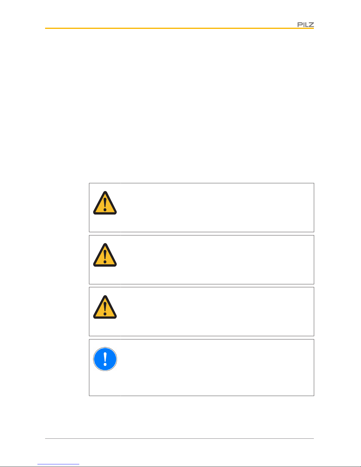
Unit view
[5]
[3]
[1]
[4] [4] [4] [4]
[5]
[3]
[6]
[2]
[1]
Receiver Transmitter
Fig.: Front view of the safety light grid transmitter and receiver, protected field height 300-1800 mm
with connection cable
Legende
[1] Protected field height
[2] Effective protected field height
[3] Tinted front panel
[4] LEDs for status information
Page 9
PSEN opII3F Series
Operating Manual PSEN opII3F Series
1003504-EN-01
9
[5] Connection cable, M12 connector
[6] Optical centre axis
[5]
[3]
[1]
[4] [4] [4] [4]
[5]
[3]
[7]
[6]
[2]
[1]
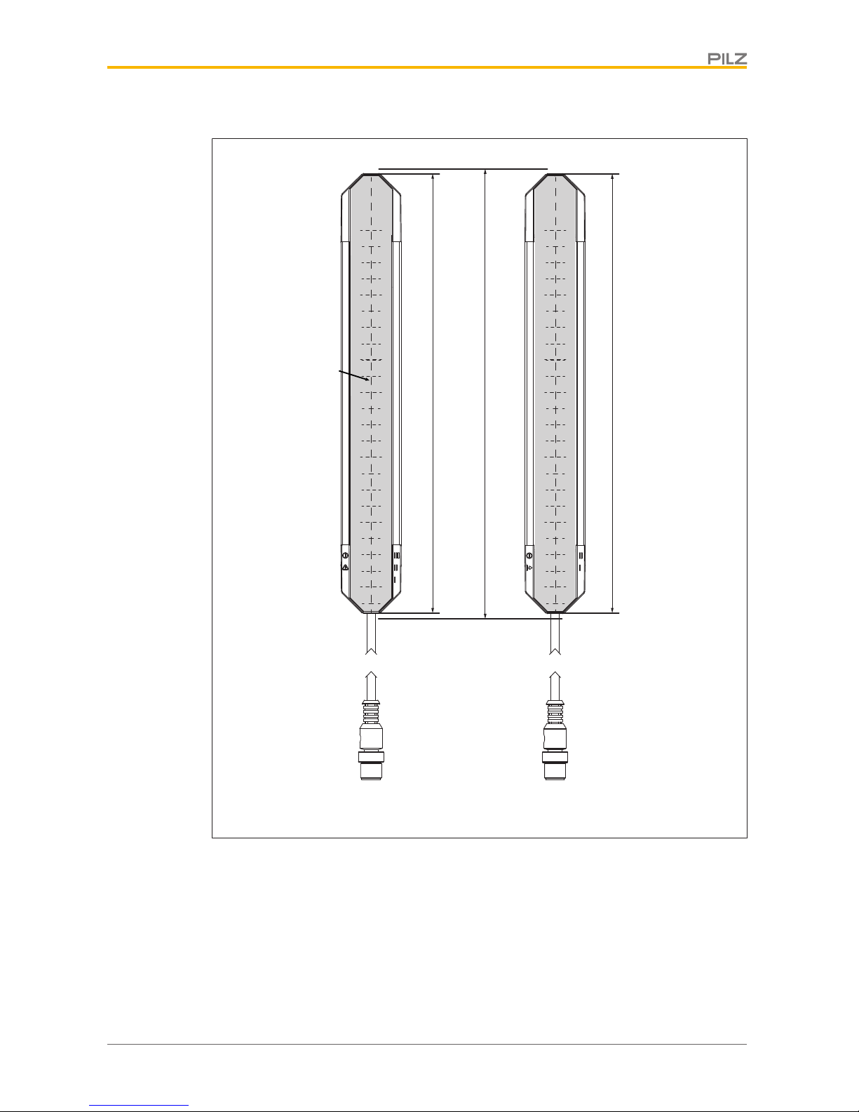
Receiver Transmitter
Fig.: Front view of the safety light grid transmitter and receiver, protected field height 150 mm with
connection cable
Legende
[1] Protected field height
[2] Effective protected field height
[3] Tinted front panel
[4] LEDs for status information
[5] Connection cable, M12 connector
[6] Optical centre axis
Page 10
PSEN opII3F Series
Operating Manual PSEN opII3F Series
1003504-EN-01
10
[7] Dead zone
The beginning of the dead zone is indicated by black lines on both sides of the
front panel
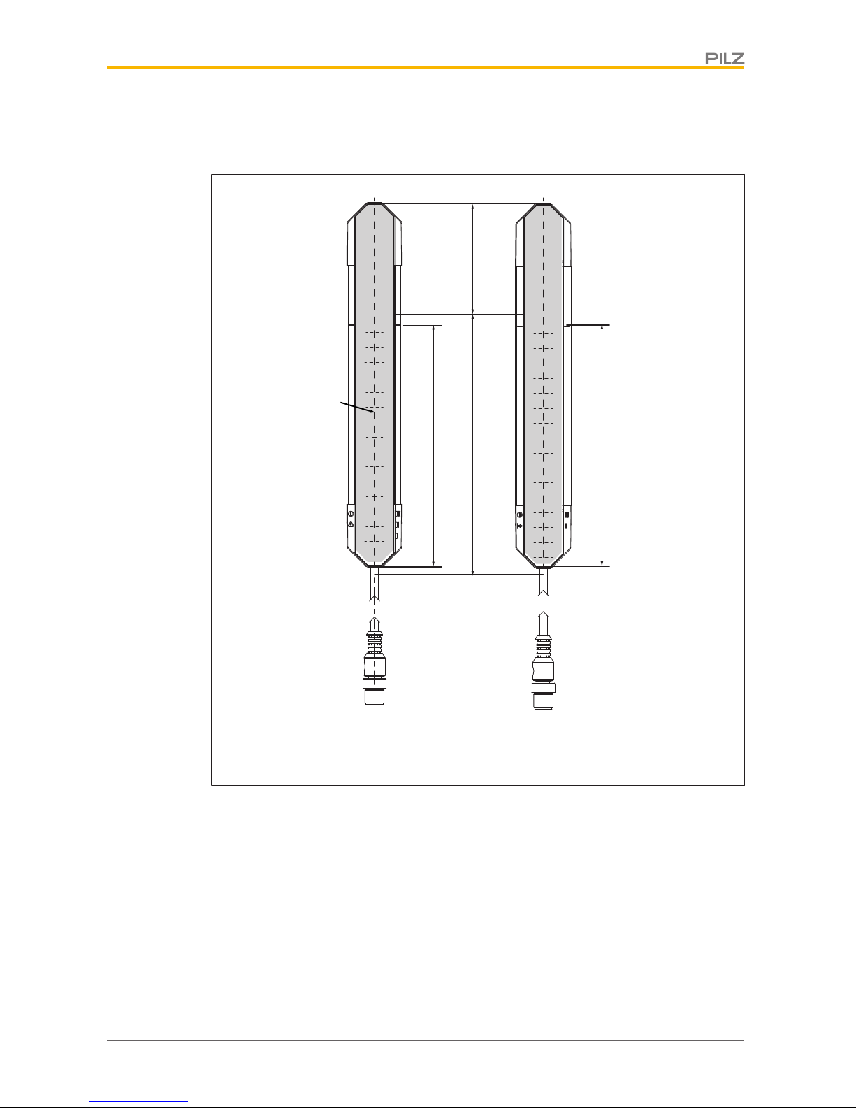
Scope
Qty Description Diagram
1 Transmitter
1 Receiver
4 Standard installation kit
consisting of:
4
} Flexible bracket
(swivel mount) in
which transmitters/receivers can be
fastened and rotated
to the proper orientation
4
} Holder for connecting
the transmitter/receiver end caps to
the flexible bracket
16
} Tightening screw
M3x33.4 oval-head
screw, self-tapping
4
} Clamping screw with
nut
ISO4762 M4x10 8.8
cylinder screw with
nut
8
} Mounting screw
ISO4762 M6x20 8.8
cylinder screw with
washer
Page 11

PSEN opII3F Series
Operating Manual PSEN opII3F Series
1003504-EN-01
11
Safety
Intended use
Safety light grids of the PSEN opII3F Series are electrosensitive protective equipment of
the 3. They are used to protect personnel and systems. The safety light grids are designed
for
} securing hazardous areas within buildings and
} securing access within buildings with a resolution of 14 mm.
The safety light grid may only be used for personal protection on machinery if
} the hazardous state can be removed by the safety light grid and
} the starting of the machine is controlled by the safety light grid and
} the safety assessment prescribes no better resolution than 14 mm.
The safety level PL d (Cat. 3 )/SIL CL 2 is only achieved if
} the safety outputs use 2-channel processing.
The safety light grid is not equipped with a restart interlock.
If the safety assessment necessitates a restart interlock, this feature must be ensured
within the plant’s programmable safety system. The system may not be started in the hazardous area following a protection violation if personnel are still in the hazardous area.
Prevent circumvention of the protected field. This means that other safety devices and safeguards may be required in addition to the safety light grid. These should be determined via
a safety assessment based on the specific application area and specific local conditions
(e.g. official specifications).
Refer to IEC/TS 62046 to determine other necessary safeguards for securing the hazardous area.
Their application must fulfil the site’s relevant national regulations (e.g.EN60204-1,
NFPA79:17-7).
The following is deemed improper use in particular:
} Any component, technical or electrical modification to the product
} Use of the product outside the areas described in this manual
} Use of the product outside the technical details (see Technical details [ 42]).
NOTICE
EMC-compliant electrical installation
The product is designed for use in an industrial environment. The product
may cause interference if installed in other environments. If installed in other
environments, measures should be taken to comply with the applicable
standards and directives for the respective installation site with regard to interference.
Page 12

PSEN opII3F Series
Operating Manual PSEN opII3F Series
1003504-EN-01
12
Safety regulations
Safety assessment
Before using a unit it is necessary to perform a safety assessment in accordance with the
Machinery Directive.
Functional safety is guaranteed for the product as a single component. However, this does
not guarantee the functional safety of the overall plant/machine. In order to achieve the required safety level for the overall plant/machine, define the safety requirements for the
plant/machine and then define how these must be implemented from a technical and organisational standpoint.
Use of qualified personnel
The products may only be assembled, installed, programmed, commissioned, operated,
maintained and decommissioned by competent persons.
A competent person is someone who, because of their training, experience and current professional activity, has the specialist knowledge required to test, assess and operate the
work equipment, devices, systems, plant and machinery in accordance with the general
standards and guidelines for safety technology.
It is the company’s responsibility only to employ personnel who:
} Are familiar with the basic regulations concerning health and safety / accident preven-
tion
} Have read and understood the information provided in this description under "Safety"
} And have a good knowledge of the generic and specialist standards applicable to the
specific application.
Warranty and liability
All claims to warranty and liability will be rendered invalid if
} The product was used contrary to the purpose for which it is intended
} Damage can be attributed to not having followed the guidelines in the manual
} Operating personnel are not suitably qualified
} Any type of modification has been made (e.g. exchanging components on the PCB
boards, soldering work etc.).
Disposal
} In safety-related applications, please comply with the mission time TM in the safety-re-
lated characteristic data.
} When decommissioning, please comply with local regulations regarding the disposal of
electronic devices (e.g. Electrical and Electronic Equipment Act).
Page 13

PSEN opII3F Series
Operating Manual PSEN opII3F Series
1003504-EN-01
13
Function description
Basic function
The safety light grid consists of a transmitter and a receiver.
Their shape and design
} protect the transmitter and receiver from external damage
} protect the safety light grid from malfunctions caused by vibration (see Technical de-
tails, environmental data section [ 42]).
The protected area is covered by infrared light beams, which are emitted from the transmitter to the receiver. The protected field thus produced is able to detect an opaque object.
The control and monitoring of the transmitted and received infrared rays is performed by
microprocessors.
The output signal switching devices (OSSDs) switch to the OFF state when one of the following conditions is met:
} one or more light beams are interrupted by an object, a body part, or an opaque object
that is at least as large as the resolution (14 mm) covered by the safety light grid,
} an error is detected by one of the OSSDs,
} or interfering light is detected.
If an error occurs, the OSSDs remain in the OFF state. The state can be returned to the ON
state only after a successful restart [ 38] of the safety light grid.
The safety light grid of the PSEN opII3F Series offers the following functions:
} automatic start
} automatic restart
} Operation of 2 safety light grids that are parallel to one another and are installed with
the same orientation (noting the information in ambient conditions [ 20] and min-
imum separation of parallel, aligned safety light grids [ 20])
Transmitters and receivers are each electrically connected with a cable with an M12 connector that is assigned to the transmitter and receiver on the LED side.
The transmitter and receiver are optically synchronised and therefore need not be directly
connected to each other.
Information about the operating status of the safety light grid and any error state is provided
by means of LEDs.
The indicators are described in the Status Information [ 35] section.
Automatic start and restart
Automatic start
During safety light grid commissioning, the safety light grid starts automatically, and the
OSSDs switch to the ON state under the following conditions:
} both OSSDs are wired correctly and
} no error has occurred and
} the protected field is clear.
If the protected field is violated, the OSSDs switch to the OFF state.
Page 14
PSEN opII3F Series
Operating Manual PSEN opII3F Series
1003504-EN-01
14
Automatic restart
The OSSDs automatically switch to the ON state during operation under the following conditions:
} both OSSDs are wired correctly and
} no error has occurred and
} the protected field is clear and
} at least 80 ms have elapsed since the switch to the OFF state.
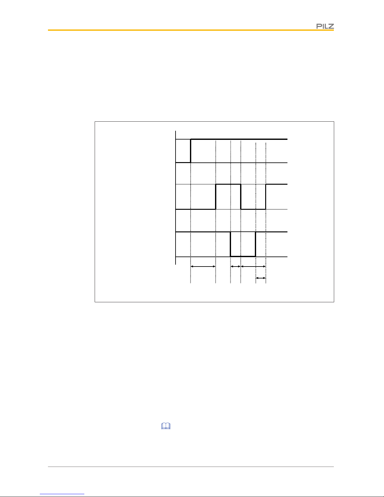
[1] [2] [3] [4] [5]
POWER
OSSD
2 3
4
[6]
t
1
tt
t
Protected
field
Free
Interrupted
ON
OFF
ON
OFF
Fig.: Automatic start and restart timing diagram
Legende
[1] Safety light grid is switched on
[2] Check completed successfully, OSSDs in the ON state
[3] Protected field broken
[4] OSSDs in the OFF state
[5] Protected field is clear again, check for errors is restarted
[6] OSSDs in the ON state
t
1
Check is begun to determine whether the protected field is clear and whether
there are errors
t
2
Response time required for the OSSDs to switch to the OFF state (see Tech-
nical details [ 42])
t
3
Minimum time that the OSSDs remain in the OFF state: 80ms
Page 15

PSEN opII3F Series
Operating Manual PSEN opII3F Series
1003504-EN-01
15
t
4
Interval between enabling of the protected field and the OSSD’s change to the
ON state
} If a synchronisation beam pair is interrupted: Response time+10ms
} If both synchronisation beam pairs (first and last light beam pair) are inter-
rupted: typically600ms (no more than4s)
Project configuration
Maintaining the safety distance
The minimum distance between the safety light grid and the hazardous machine component should be such that the operator cannot reach the hazardous area until the hazardous
machine part has come to a standstill.
In accordance with the standard
} ENISO13855
this distance depends on three factors:
} Response time of the safety light grid
Interval between interruption of the beams and the OSSD’s change to the OFF state
} Machine's stopping time
Interval between the change of the OSSD to the OFF state and the stopping of the hazardous machine movement (including the reaction time of the connected relay)
} Approach speed
The speed with which the object to be detected is nearing the hazardous area in mm/s
The general formula for calculating the minimum distance in accordance with
ENISO13855 is as follows:
S = K * (t1 + t2) + C
S Minimum distance in mm, measured from the start of the protected field to the
danger source
K Approach speed with which the object to be detected is nearing the hazardous area
in mm/s
K = 1600 mm/s when S > 500 mm
K = 2000 mm/s when S ≤ 500 mm
t1Response time of the safety light grid in seconds
Time it takes for the signal at the OSSD output on the safety light grid to change
once a protected field has been violated
t2Machine's stopping time in seconds
The time required for the machine to stop after the signal at the OSSD output
changes
C Additional distance of 0 mm for safety light grids with finger protection
Page 16

PSEN opII3F Series
Operating Manual PSEN opII3F Series
1003504-EN-01
16
Resolution
The safety light grids may only be used for protected fields in which a detection capability of
14 mm is sufficient.
Protected field perimeters
During planning, ensure sufficient protected field height to secure the hazardous area.
The protected field perimeter is defined in dimensions [ 40].
Ambient conditions
} Install the safety light grids in an environment that corresponds to the environmental
data provided in the Technical details [ 42].
} Do not install the safety light grid near particularly intense and/or flashing light sources;
this applies to the receiver in particular.
} The transmitter of one safety light grid must not interfere with the receiver of another
safety light grid.
} The transmitters and receivers of two different safety light grids must not be synchron-
ised.
} Avoid strong electromagnetic interference when operating the safety light grid.
} When operating the safety light grid, avoid the development of smoke, mist, or dust that
would reduce the grid’s operating range.
Page 17
PSEN opII3F Series
Operating Manual PSEN opII3F Series
1003504-EN-01
17
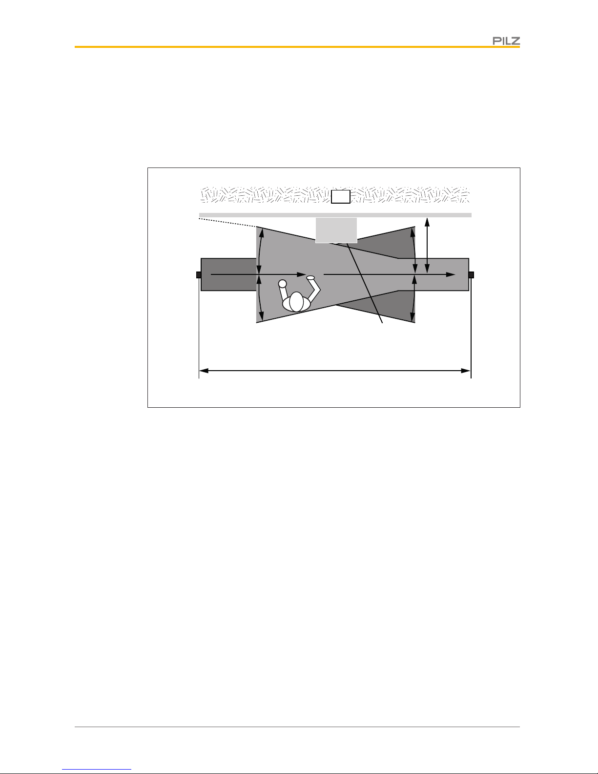
Distance from reflective surfaces
If there are reflective surfaces near the beams emitted from the safety light grid (whether
from above, below, or from the side), passive reflections can cause an object within the protected field to remain undetected (see diagrams).
This means that there must be a certain minimum distance between the safety light grid
and reflective surfaces.
[1]
[2]
[3]
[5]
[6]
[4]
[4] [4]
[4]
[7]
[8]
Fig.: Interference with the function of the safety light grid due to reflective surfaces – top view
Page 18

PSEN opII3F Series
Operating Manual PSEN opII3F Series
1003504-EN-01
18
[1]
[2] [3]
[4]
[4]
[4]
[4]
[5]
[1]
[5]
Legend
[1] Reflective surface
[2] Transmitter
[3] Receiver
[4] Half of the opening angle [ 42] (= ⍺) of the light beams emitted by the safety
light grid
[5] Minimum distance D between the safety light grid and the reflective surface
[6] Passive reflections on the surface
[7] Distance between transmitter and receiver (working distance)
[8] Hazardous area
The minimum distance D depends on two factors:
} Working distance between transmitter and receiver
} the maximum opening angle [ 42] of the light beams emitted by the safety light grid
at:
5° = ± 2.5° in relation to the optical axis
Page 19

PSEN opII3F Series
Operating Manual PSEN opII3F Series
1003504-EN-01
19
Minimum distance of the safety light grid to reflective surfaces
The formula for calculating the minimum distance D is:
} For a working distance of less than 3 m: D = 0.131 m
} For a working distance of 3 m or more: D = working distance in m x tan ⍺
[2]
0,35
0,174
0,131
0 3 4 8 [1]
Fig.: Relationship between minimum distance and working distance
Legende
[1] Working distance in m
[2] Minimum distance D to reflective surfaces in m
Page 20

PSEN opII3F Series
Operating Manual PSEN opII3F Series
1003504-EN-01
20
Minimum distance between parallel, aligned safety light grids
Please note:
Safety light grids that are installed so as to be parallel and aligned must have a minimum
spacing corresponding to the information in distance to reflective surfaces.
[1]
[2]
[3]
[4]
[5]
[6]
[7]
[8]
[7]
Legend
[1] Transmitter from the first safety light grid
[2] Receiver from the first safety light grid
[3] Transmitter from the second safety light grid
[4] Receiver from the second safety light grid
[5] Minimum distance of 2 x D between two safety light grids that are aligned
[6] Working distance
[7] Minimum distance D, dependent on the working distance
[8] Working distance (= 3m) with constant minimum distance D=0.131m
Page 21

PSEN opII3F Series
Operating Manual PSEN opII3F Series
1003504-EN-01
21
Installation of several adjacent safety light grids
An arrangement of several adjacent safety light grids can be achieved by various methods.
When installing of several adjacent safety light grids, note the ambient conditions [ 16].
[1] [2] [3]
[4]
[5]
[4]
[5]
[4]
[5]
Hazardous area
Fig.: Using several adjacent safety light grids
Legende
[1] Connecting the safety light grid with an opaque surface to shield the safety light
grid on the right
[2] Connection of the safety light grid aligned with [1]
[3] Connection of safety light grid without shielding, but in the orientation opposite to
[2]
[4] Receiver
[5] Transmitter
Use of deviating mirrors
Hazardous areas with different but adjacent access sides can be monitored using a safety
light grid in conjunction with deviating mirrors [ 53].
The diagram below shows an example solution for monitoring three different access sides
using two deviating mirrors. The deviating mirrors must be positioned at an angle of 45° to
the beams from the safety light grid.
When using deviating mirrors, please note:
} Even a minor angular displacement of the mirror can lead to misalignment, adversely
affecting or preventing the function of the safety light grid. Use the laser pointer PSEN
opII for alignment (see Order reference for accessories [ 53]).
} The minimum safety distance to the hazardous area must be maintained for all sections
of the light path.
} Use of a single deviating mirror reduces the operating range by about 20%. This per-
centage increases when an additional deviating mirror is used (more detailed information is provided in the technical data for the relevant mirror). Please consider this reduction when positioning the safety light grid.
} You should not use more than two mirrors per device.
} Any dust or dirt on the mirror’s reflective surface will drastically reduce the operating
range.
Page 22

PSEN opII3F Series
Operating Manual PSEN opII3F Series
1003504-EN-01
22
[1][2]
[5]
[6]
[4]
[7][8]
[3]
[4]
[5]
[5]
Fig.: Example for using deviating mirrors
Legende
[1] Transmitter
[2] Receiver
[3] Hazardous area
[4] Deviating mirrors
[5] Minimum safety distance
[6] Distance between the deviating mirrors (see the following table)
[7] Distance from transmitter to deviating mirror
[8] Distance from deviating mirror to receiver
Number of mirrors per device
Maximum operating range [ 42] in
m
1 6.4 m (8 m – 20%)
2 5.12 m (8 m – 2 x 20%)
Dead zones
Use of the standard installation kit results in a dead zone of 15.4mm on both sides of the
safety light grid.
If you want to use the safety light grid without dead zones, use the
PSENopIIAdvBracketKit for safety light grid installation (see Dead-zone-free
installation [ 6]).
Page 23

PSEN opII3F Series
Operating Manual PSEN opII3F Series
1003504-EN-01
23
Use the installation information provided in the PSENopIIAdvBracketKit operating
manual.
[1]
[2]
[3]
[4]
Fig.: Placement of the dead zones in vertical safety light grid installation
Legende
[1] Last light beam (wiring side)
[2] Last light beam (cable side)
[3] Wiring-side dead zone
[4] Cable-side dead zone
Page 24

PSEN opII3F Series
Operating Manual PSEN opII3F Series
1003504-EN-01
24
Installation and orientation
Please note:
} The optical surfaces of the transmitter and receiver must be parallel to each other and
oriented opposite to each other.
} The connection sides of the transmitter and receiver must be on the same side and at
the same height (see diagram).
[1] [2] [1] [2]
[3]
[3]
[3]
[3]
True False
Legend
[1] Transmitter
[2] Receiver
[3] Connection cable
} The distance between the transmitter and receiver must be within the operating range
of the safety light grid used (see Technical details [ 42]).
} The installation surface must be at least as wide as the standard installation kit
} The installation surface may have a flatness imperfection of no more than 1.5mm.
Page 25

PSEN opII3F Series
Operating Manual PSEN opII3F Series
1003504-EN-01
25
Attach the safety light grid to the installation surface
[2]
[3]
[1]
Please note the following when installing the
safety light grid [1]:
If the standard installation kit is used, the gap [2]
between the safety light grid [1] and the installation
surface [3] must be smaller than the safety light grid
resolution.
Prepare the installation surface.
Clean the installation surface. The installation surface must be free of dust and grease.
[1]
[1]
[2]
Mount the holder on the end cap on the connection side of the safety light grid
Feed the cable [2] through the opening in the holder.
Ensure that the holder is flush with the end cap (see
diagram).
Attach the holder to the end cap with the tightening
screws included in delivery.
[1] Torque setting 0,7 Nm
Page 26

PSEN opII3F Series
Operating Manual PSEN opII3F Series
1003504-EN-01
26
[1]
[1]
Mount the holder on the end cap on the wiring side
of the safety light grid
Ensure that the holder is flush with the end cap (see
diagram).
Attach the holder to the end cap with the tightening
screws included in delivery.
[1] Torque setting 0,7 Nm
[1]
[2]
Mount the flexible bracket (swivel mount) on the
holder on both the connection and wiring sides of
the safety light grid.
Push the flexible bracket over the holder. The flexible
bracket must lie flush with the holder.
Fix the flexible bracket in place with the clamping
screw [1] and the nut [2].
The screw connection is only tightened to the final
torque when the assembly is orientated.
[1]
[2]
[3]
[4]
a
Uneven installation surfaces can be compensated for
with the standard installation kit to a limited extent
only.
Please note the following when installing the
safety light grid [1]:
} The angle [4] of the flexible bracket [3] on the
holder [2] may not be more than 2°.
} The flexible bracket [3] must be seated on one side
of the holder [2].
Page 27

PSEN opII3F Series
Operating Manual PSEN opII3F Series
1003504-EN-01
27
14,5
6
6,3
19
Bore holes in the installation surface (two M6 screw
boreholes per flexible bracket) for mounting the flexible
brackets for the transmitter and receiver.
[1]
Fix the transmitter and receiver and their flexible
brackets in place on the installation surface.
For each bracket, use two mounting screws with washers [1] included in delivery [ 10]. If necessary,
mounting screws with deviating lengths can be used.
Transmitters and receivers can be shifted vertically
and horizontally.
The screw connection is only tightened to the final
torque when the assembly is orientated.
Ensure that the transmitters and receivers are properly
installed in a suitable place.
Ensure that the transmitters and receivers are positioned at the same height and parallel to one another.
Page 28

PSEN opII3F Series
Operating Manual PSEN opII3F Series
1003504-EN-01
28
Orientation
General guidelines
For the safety light grid to function properly, the transmitter and receiver must be correctly
aligned.
The transmitter and receiver on the safety light grid can be aligned with our without the help
of a laser alignment aid.
} Alignment with laser alignment aid: the safety light grid does not need to be switched on
} Alignment without laser alignment aid: the safety light grid must already be wired (see
chapter entitled "Wiring" in the safety grid's operating manual) and must be switched on
For alignment Pilz recommends the PSEN opII Laserpointer (see Order references for
accessories [ 53]) or another laser alignment aid.
[3]
[1]
[2]
Fig.: Transmitter/receiver modification directions during orientation
Legende
[1] Vertical: by vertical shifting of position in the elongated holes in the top and bottom
flexible brackets
[2] Horizontal: by horizontal shifting of position in the elongated holes in the top and bot-
tom flexible brackets
[3] The axis orientation can be changed by rotating the flexible bracket right or left
Pilz recommends that modifications to the orientation of the transmitter/receiver be made in
the following sequence:
1. Vertical modification
2. Horizontal modification
3. Axis orientation modification
Page 29

PSEN opII3F Series
Operating Manual PSEN opII3F Series
1003504-EN-01
29
Safety light grid alignment
Optimum alignment using a laser alignment aid
Optimum alignment with a laser alignment aid is achieved when the following conditions apply:
} Beam from the laser alignment aid on the transmitter strikes the receiver and
} Beam from the laser alignment aid on the receiver strikes the transmitter
Perform the orientation as described in the laser orientation aid’s operating manual.
WARNING!
The laser beam of the laser orientation aid is harmful to the human eye
The human eye may be injured.
– Ensure that the laser beam is not directed at a human eye.
Optimal orientation without a laser orientation aid
1. Determine the maximum rotation range in when the protected field LED (OSSD status)
illuminates green.
Rotate the transmitter and receiver until the protected field LED (OSSD status) changes
from red to green.
2. Rotate the transmitter to the centre of the rotation range in which the protected field
LED illuminates green.
3. Rotate the receiver to the centre of the rotation range in which the protected field LED
illuminates green.
After the safety light grid’s transmitter and receiver have been orientated, the clamping
screws and nuts and the mounting screws must be tightened to their final torques.
} Tighten the clamping screws [1] and the nuts [2] on the flexible bracket to a torque of
1,1 Nm.
} Tighten the brackets’ mounting screws [3] on the installation surface to a torque of 3
Nm.
Page 30

PSEN opII3F Series
Operating Manual PSEN opII3F Series
1003504-EN-01
30
[1]
[2]
[3]
Legend
[1] Clamping screw
[2] Nut
[3] Mounting screws
Wiring
General guidelines
} Do not lay the connecting cable near or in contact with cables that carry high or highly
volatile currents.
} Use separate cables to connect the wires to the OSSDs on different safety light grids or
safety switches.
} Do not connect contacts OSSD1 and OSSD2 in series or in parallel.
} For supply voltage, use only PELV/SELV power supplies that have a voltage buffer in
accordance with EN60204-1.
} The power supply must be able to bridge a short (20ms) supply voltage failure in ac-
cordance with EN61496-1.
} SELV power supply
– Do not connect the safety light grid housing to the earth conductor or the protective
conductor. The transmitters and receivers must be electrically isolated from the machine/system. The use of the flexible bracket (swivel mount) provides this electrical
isolation.
} Connection to PDP67
– Use the order reference of the cable listed (see Accessories, connection to
PDP67 [ 54])
Page 31

PSEN opII3F Series
Operating Manual PSEN opII3F Series
1003504-EN-01
31
} Connection to other evaluation devices
– Use the order reference of the cable listed (see Accessories, connection to other
evaluation devices [ 54])
– The clamps for connection to the evaluation device must be kept in a locked control
cabinet. This prevents unauthorised modifications.
} Ensure compliance with permissible cable bending radii (see Technical
details [ 42]).
Connector pin assignment
Transmitter and receiver electrical connections are made with M12 connectors. These connectors are located on the bottom of the transmitters and receivers.
} Ensure that the wiring has been performed as indicated. Pins 1 and 5 must be connec-
ted to 24VDC, otherwise, the correct functionality is not guaranteed.
5-pin connector on the transmitter PIN Assignment Cable colour
1
2
3
4
5
1 +24 VDC brown
2 reserved white
3 0 VDC blue
4 reserved black
5 +24 VDC grey
5-pin connector on the receiver PIN Assignment Cable colour
1
2
3
4
5
1 +24 VDC brown
2 OSSD 1 white
3 0 VDC blue
4 OSSD 2 black
5 +24 VDC grey
Earthing the safety light grid
Please note:
} Connect the 0 V connections on all the 24 V power supplies and earth the 0 V mains at
a single point, or ensure that measures are in place to monitor for earth faults.
} The connection of the 0 V supply to the central earth bar or earth fault monitor must be
in accordance with relevant national regulations (such as EN60204-1, NFPA79:17-7,
NEC:Article250).
} Connections should be protected from corrosion.
} Flexible earthing straps should be used on moving earth parts (e.g. machine parts,
gates). Ensure these earthing straps are as short and wide as possible.
Page 32

PSEN opII3F Series
Operating Manual PSEN opII3F Series
1003504-EN-01
32
} For PELV power supplies
Connect the power supply circuit to the earth conductor.
Commissioning
System connection
Make sure that the selected evaluation device has the following properties:
} 2-channel with feasibility monitoring
} OSSD signals are evaluated
} A test pulse lasting no longer than 300 µs is bridged
Suitable Pilz evaluation devices are, for example:
} PNOZelog for monitoring safety light grids
} PNOZsigma for monitoring safety light grids
} PNOZ X for monitoring safety light grids
} PDP67 ION and PDP67 ION HP
Make the connection using one of the cables listed in the order reference (see Order
reference for accessories, connection to PDP67 [ 54]).
} PNOZmulti for safety light grid monitoring
Configure the safety light grid in the PNOZmulti Configurator with switch type 3.
} Automation system PSS 4000 for monitoring safety light grids with the FS_LightCurtain
function block
The correct connection to the respective evaluation device is described in the operating
manual for the evaluation device. Connect the evaluation device according to the specifications in the selected evaluation device’s operating manual.
Page 33

PSEN opII3F Series
Operating Manual PSEN opII3F Series
1003504-EN-01
33
5
3
1
2
4
5
3
1
0 V 24 V
24 V
0 V
24 V
OSSD 1
OSSD 2
24 V
0 V
24 V
PSENopII
receiver
PSENopII
transmitter
Evaluation device
Input circuit
External
supply voltage
Fig.: Dual-channel connection of the safety light grid to the input circuit of an evaluation device
CAUTION!
When considering the examples, please note that Pilz accepts no responsibility for the specific application. In particular, they may not be used without
testing and approval.
The system manufacturer is responsible for creating appropriate safety concepts for the overall plant and for connection to the programmable safety
system (including the user program). The applicable standards and regulations must be considered and observed.
Checking the safety light grid
Once the safety light grid has been installed and aligned, final inspections must be carried
out before it can be put into service.
INFORMATION
This inspection may only be carried out by qualified personnel.
Page 34

PSEN opII3F Series
Operating Manual PSEN opII3F Series
1003504-EN-01
34
Check the safety function of the safety light grid
Procedure
In each of the indicated checks, the OSSDs must switch to the OFF state.
The OSSD status LED on the left side of the receiver must illuminate red.
1. Move the test rod slowly through the protected field (see diagram):
– In the vicinity of the transmitter
– In the vicinity of the receiver
– In the centre of the protected field
2. Place the test rod at rest in a position in the protected field that is considered critical for
the safety assessment results
[1]
Legend
[1] Test rod
Page 35

PSEN opII3F Series
Operating Manual PSEN opII3F Series
1003504-EN-01
35
Check ambient conditions and installation
} Correct orientation and attachment
Check the seating of the mounting screw by applying pressure to edge of the safety
light grid. Neither the device status LED of the transmitter nor that of the receiver
may illuminate.
} Safety distance
The safety distance must comply with the requirements in Maintaining the safety
distance [ 15].
} Circumvention of the protected field
The hazardous zone must be secured so that it is impossible to access by circumventing the protected field
} Protected field perimeters
The protected field perimeters (see Dimensions [ 40]) must completely secure the
hazardous area, making it inaccessible.
} Response and stopping times must fulfil the requirements in Maintaining the safety
distance [ 15]
Ensure that the safety light grid's response time and the machine's stopping time fulfil
the requirements in Maintaining the safety distance [ 15].
} No intense or flashing light sources in the vicinity
There may be no especially intense or flashing light sources in the vicinity of the safety
light grid.
} Ambient conditions
Please observe the environmental conditions [ 16].
} Use of deviating mirrors
Check all areas that are bounded by a deviating mirror.
Operation
Display elements
The safety light grid’s operating status is indicated with LEDs in the end caps of the connection side of the receiver and on the transmitter.
Device status Reception quality:
III: best quality
I: worst quality
OSSD status (protected field LED)
LED indicator on the receiver
Page 36

PSEN opII3F Series
Operating Manual PSEN opII3F Series
1003504-EN-01
36
Device status Light beam error information
Light beam status
LED indicators on the transmitter
Status information
Legend
LED on
LED flashes
LED off
Displays on the receiver
Meaning
green green
Ready for operation
The current reception quality
status is indicated
green red green green green
Safety light grid is started
green red
Protected field is interrupted
red red
OSSD error.
Perform a safety light grid
restart [ 38].
red red
An error has occurred.
Perform a safety light grid
restart [ 38].
green
green
green green green
Interfering light warning
Warns of the OSSDs’ change to
the OFF state due to incident interfering light.
Page 37

PSEN opII3F Series
Operating Manual PSEN opII3F Series
1003504-EN-01
37
Meaning
red
red
green green green
Interfering light error
OSSDs have changed to the OFF
state due to incident interfering
light.
1. Install an opaque surface on
the side facing the interfering
light source or
reverse the positions of the
safety light grid’s transmitter
and receiver.
2. Perform a safety light grid
restart [ 38].
red
red
green
Overtemperature; OSSD in the
OFF state
1. Ensure that the ambient temperature corresponds to the information in the Technical
details [ 42].
2. Perform a safety light grid
restart [ 38].
red
red
green
Undervoltage; OSSD in the OFF
state
1. Ensure that the supply voltage
corresponds to the information
in the Technical
details [ 42].
2. Perform a safety light grid
restart [ 38].
Indicators on the transmitter
Meaning
green red green green
Safety light grid is started
green green
Safety light grid in operation
red red
An error has occurred.
Perform a safety light grid
restart [ 38].
Page 38

PSEN opII3F Series
Operating Manual PSEN opII3F Series
1003504-EN-01
38
Meaning
red
red
green
Overtemperature; OSSD in the OFF
state
1. Ensure that the ambient temperature
corresponds to the information in the
Technical details [ 42].
2. Perform a safety light grid
restart [ 38].
red
red
green
Undervoltage; OSSD in the OFF state
1. Ensure that the supply voltage corresponds to the information in the
Technical details [ 42].
2. Perform a safety light grid
restart [ 38].
Safety light grid restart
a Disconnect the supply voltage from the safety light grid and reconnect it. The automatic
restart [ 14] begins.
Malfunction
DANGER!
Loss of safety function due to a malfunction of the safety light grid
A safety light grid malfunction may lead to serious injury or death.
If there is a safety light grid malfunction, immediately discontinue operation
of the system components whose hazardous area the grid secures.
Regular checks and maintenance
Checks
Regular checks can bring to light changes to the plant/machine, safeguards and ambient
conditions.
Regular check
Pilz recommends that the safety light grid be checked every six months.
} Check the safety light grid’s front panel.
– Scratched front panel: Replace the safety light grid.
– Dirty front panel: Clean the front panel [ 39].
In a particularly dirty environment, front panel cleanliness should be checked more
frequently.
Page 39

PSEN opII3F Series
Operating Manual PSEN opII3F Series
1003504-EN-01
39
} Check the tightness of the safety light grid’s front panel.
All screws must be tightened to the torque specified in the Technical details [ 42].
} Check the safety function of the safety light grid (see Check the safety function of the
safety light grid [ 34]).
Check after plant/machine modification
Check the safety light grid each time the plant/machine is modified. Changing the safety
light grid or swapping safety light grid components should be regarded as a modification.
The requirements of the applicable national regulations must be observed absolutely.
INFORMATION
This inspection may only be carried out by qualified personnel.
The Appendix contains a Checklist [ 56] which should help you perform the safety
check.
Maintenance
Other than cleaning the lens covers, the safety light grids requires no other form of maintenance.
CAUTION!
Improper cleaning agents can damage the safety light grid and lead to malfunctions
Moist cotton cloths should be used for cleaning.
Avoid using
} Alcohol,
} Solvents,
} Cloths made of wool,
} Cloths made of synthetic material.
Clean the lens covers during the regular check of the safety light grid [ 38].
Page 40

PSEN opII3F Series
Operating Manual PSEN opII3F Series
1003504-EN-01
40
Dimensions
M12x1
35
17,5 17,5
13,5
4,7 ±1
13,5
[1]
[2]
4,7 ±1
[3]
ø14,5
ø5
42
[4]
[5]
[6]
[7]
Fig.: Front view of the safety light grid transmitter, protected field height 300-1800 mm with connection cable
Legende
[1] Total length of transmitter (without cable)
[2] Effective protected field height
[3] Protected field height (see Technical details [ 42])
[4] Optical centre axis
[5] Cable-side beam pair for beam synchronisation
[6] Wiring-side beam pair for beam synchronisation
[7] Eye shield
35
17,5 17,5
13,5
13,5
[1]
[2]
4,7 ±1
[3]
[4]
[5]
[6]
[7]
[8]
[9]
Fig.: Front view of the safety light grid transmitter, protected field height 150 mm with connection cable
Legende
[1] Total length of transmitter (without cable)
[2] Effective protected field height
[3] Protected field height (see Technical details [ 42])
Page 41

PSEN opII3F Series
Operating Manual PSEN opII3F Series
1003504-EN-01
41
[4] Optical centre axis
[5] Cable-side beam pair for beam synchronisation
[6] Wiring-side beam pair for beam synchronisation
[7] Eye shield
[8] Dead zone 70.3 mm
[9] Protected field perimeter markings
Schematic representation of the relationship between the safety light grid
dimensions and the effective protected field height
[1]
[2]
[3][4] [5][6]
[1]
Fig.: Relationship between the effective protected field height and the safety light grid dimensions
(schematic representation)
Legende
[1] Resolution
[2] Last light beams on the connection and wiring sides
[3] Protected field height
[4] Effective protected field height
[5] Transmitter
[6] Receiver
Page 42

PSEN opII3F Series
Operating Manual PSEN opII3F Series
1003504-EN-01
42
Technical details Order no. 632040-632042
General 632040 632041 632042
Approvals CE, TÜV CE, TÜV CE, TÜV
ESPE type 3 3 3
Sensor's mode of operation Infrared Infrared Infrared
Height of protected field 150 mm 300 mm 450 mm
Resolution
Operating range 0,2 - 8 m 0,2 - 8 m 0,2 - 8 m
Detection capability 14 mm 14 mm 14 mm
Electrical data 632040 632041 632042
Supply voltage
Voltage 24 V 24 V 24 V
Kind DC DC DC
Voltage tolerance -25 %/+20 % -25 %/+20 % -25 %/+20 %
Residual ripple DC 5 % 5 % 5 %
Max. power consumption
receiver 12 W 12 W 12 W
Max. power consumption
transmitter 7,2 W 7,2 W 7,2 W
Max. inductive load per
output 1 H 1 H 1 H
Optical data 632040 632041 632042
Opening angle -2,5 - 2,5 deg -2,5 - 2,5 deg -2,5 - 2,5 deg
Used wavelength range 850 nm 850 nm 850 nm
Inputs 632040 632041 632042
Max. overall line capacitance Clmax 40 nF 40 nF 40 nF
Semiconductor outputs 632040 632041 632042
OSSD safety outputs 2 2 2
Switching current per output 100 mA 100 mA 100 mA
Times 632040 632041 632042
Test pulse duration, safety
outputs 300 µs 300 µs 300 µs
Supply interruption before
de-energisation 600 µs 600 µs 600 µs
Response time t1 14 ms 14 ms 15 ms
Page 43

PSEN opII3F Series
Operating Manual PSEN opII3F Series
1003504-EN-01
43
Environmental data 632040 632041 632042
Ambient temperature
Temperature range -10 - 60 °C -10 - 60 °C -10 - 60 °C
Storage temperature
Temperature range -25 - 70 °C -25 - 70 °C -25 - 70 °C
Climatic suitability
Humidity 95 % r. h. at 50 °C 95 % r. h. at 50 °C 95 % r. h. at 50 °C
Condensation during operation Not permitted Not permitted Not permitted
EMC EN 61496-1 EN 61496-1 EN 61496-1
Vibration
In accordance with the
standard EN 60068-2-6 EN 60068-2-6 EN 60068-2-6
Frequency 10 - 150 Hz 10 - 150 Hz 10 - 150 Hz
Amplitude 0,75 mm 0,75 mm 0,75 mm
Shock stress
In accordance with the
standard EN 60068-2-27 EN 60068-2-27 EN 60068-2-27
Number of shocks 1000 1000 1000
Acceleration 10g 10g 10g
Duration 16 ms 16 ms 16 ms
Bracket Swivel-Mount Swivel-Mount Swivel-Mount
In accordance with the
standard EN 60068-2-27 EN 60068-2-27 EN 60068-2-27
Number of shocks 3 3 3
Acceleration 50g 50g 50g
Duration 11 ms 11 ms 11 ms
Bracket Adv Bracket Kit Adv Bracket Kit Adv Bracket Kit
Protection type
Housing IP65 IP65 IP65
Mechanical data 632040 632041 632042
Min. bending radius (fixed
permanently) K1 5 x Ø 5 x Ø 5 x Ø
Min. bending radius (moving) K1 10 x Ø 10 x Ø 10 x Ø
Connection type
Receiver
M12, 5-pin male connector
M12, 5-pin male connector
M12, 5-pin male connector
Transmitter M12, 5-pin male con-
nector
M12, 5-pin male connector
M12, 5-pin male connector
Max. cable length 50 m 50 m 50 m
Page 44

PSEN opII3F Series
Operating Manual PSEN opII3F Series
1003504-EN-01
44
Mechanical data 632040 632041 632042
Material
Housing Aluminium Aluminium Aluminium
End caps Zn Zn Zn
Front screen PC PC PC
Max. torque setting
Clamping screw 1,1 Nm 1,1 Nm 1,1 Nm
Installation screw 3 Nm 3 Nm 3 Nm
Fixing screw 0,7 Nm 0,7 Nm 0,7 Nm
Dimensions
Height 229 mm 304 mm 454 mm
Width 35 mm 35 mm 35 mm
Depth 40 mm 40 mm 40 mm
Weight 780 g 1.025 g 1.438 g
Where standards are undated, the 2015-12 latest editions shall apply.
Technical details Order no. 632043-632045
General 632043 632044 632045
Approvals CE, TÜV CE, TÜV CE, TÜV
ESPE type 3 3 3
Sensor's mode of operation Infrared Infrared Infrared
Height of protected field 600 mm 750 mm 900 mm
Resolution
Operating range 0,2 - 8 m 0,2 - 8 m 0,2 - 8 m
Detection capability 14 mm 14 mm 14 mm
Electrical data 632043 632044 632045
Supply voltage
Voltage 24 V 24 V 24 V
Kind DC DC DC
Voltage tolerance -25 %/+20 % -25 %/+20 % -25 %/+20 %
Residual ripple DC 5 % 5 % 5 %
Max. power consumption
receiver 12 W 12 W 12 W
Max. power consumption
transmitter 7,2 W 7,2 W 7,2 W
Max. inductive load per
output 1 H 1 H 1 H
Page 45

PSEN opII3F Series
Operating Manual PSEN opII3F Series
1003504-EN-01
45
Optical data 632043 632044 632045
Opening angle -2,5 - 2,5 deg -2,5 - 2,5 deg -2,5 - 2,5 deg
Used wavelength range 850 nm 850 nm 850 nm
Inputs 632043 632044 632045
Max. overall line capacitance Clmax 40 nF 40 nF 40 nF
Semiconductor outputs 632043 632044 632045
OSSD safety outputs 2 2 2
Switching current per output 100 mA 100 mA 100 mA
Times 632043 632044 632045
Test pulse duration, safety
outputs 300 µs 300 µs 300 µs
Supply interruption before
de-energisation 600 µs 600 µs 600 µs
Response time t1 15 ms 16 ms 17 ms
Environmental data 632043 632044 632045
Ambient temperature
Temperature range -10 - 60 °C -10 - 60 °C -10 - 60 °C
Storage temperature
Temperature range -25 - 70 °C -25 - 70 °C -25 - 70 °C
Climatic suitability
Humidity 95 % r. h. at 50 °C 95 % r. h. at 50 °C 95 % r. h. at 50 °C
Condensation during operation Not permitted Not permitted Not permitted
EMC EN 61496-1 EN 61496-1 EN 61496-1
Vibration
In accordance with the
standard EN 60068-2-6 EN 60068-2-6 EN 60068-2-6
Frequency 10 - 150 Hz 10 - 150 Hz 10 - 150 Hz
Amplitude 0,75 mm 0,75 mm 0,75 mm
Page 46

PSEN opII3F Series
Operating Manual PSEN opII3F Series
1003504-EN-01
46
Environmental data 632043 632044 632045
Shock stress
In accordance with the
standard EN 60068-2-27 EN 60068-2-27 EN 60068-2-27
Number of shocks 1000 1000 1000
Acceleration 10g 10g 10g
Duration 16 ms 16 ms 16 ms
Bracket Swivel-Mount Swivel-Mount Swivel-Mount
In accordance with the
standard EN 60068-2-27 EN 60068-2-27 EN 60068-2-27
Number of shocks 3 3 3
Acceleration 50g 50g 50g
Duration 11 ms 11 ms 11 ms
Bracket Adv Bracket Kit Adv Bracket Kit Adv Bracket Kit
Protection type
Housing IP65 IP65 IP65
Mechanical data 632043 632044 632045
Min. bending radius (fixed
permanently) K1 5 x Ø 5 x Ø 5 x Ø
Min. bending radius (moving) K1 10 x Ø 10 x Ø 10 x Ø
Connection type
Receiver
M12, 5-pin male connector
M12, 5-pin male connector
M12, 5-pin male connector
Transmitter M12, 5-pin male con-
nector
M12, 5-pin male connector
M12, 5-pin male connector
Max. cable length 50 m 50 m 50 m
Material
Housing Aluminium Aluminium Aluminium
End caps Zn Zn Zn
Front screen PC PC PC
Max. torque setting
Clamping screw 1,1 Nm 1,1 Nm 1,1 Nm
Installation screw 3 Nm 3 Nm 3 Nm
Fixing screw 0,7 Nm 0,7 Nm 0,7 Nm
Dimensions
Height 604 mm 754 mm 904 mm
Width 35 mm 35 mm 35 mm
Depth 40 mm 40 mm 40 mm
Weight 1.850 g 2.263 g 2.675 g
Where standards are undated, the 2015-12 latest editions shall apply.
Page 47

PSEN opII3F Series
Operating Manual PSEN opII3F Series
1003504-EN-01
47
Technical details Order no. 632046-632048
General 632046 632047 632048
Approvals CE, TÜV CE, TÜV CE, TÜV
ESPE type 3 3 3
Sensor's mode of operation Infrared Infrared Infrared
Height of protected field 1.050 mm 1.200 mm 1.350 mm
Resolution
Operating range 0,2 - 8 m 0,2 - 8 m 0,2 - 8 m
Detection capability 14 mm 14 mm 14 mm
Electrical data 632046 632047 632048
Supply voltage
Voltage 24 V 24 V 24 V
Kind DC DC DC
Voltage tolerance -25 %/+20 % -25 %/+20 % -25 %/+20 %
Residual ripple DC 5 % 5 % 5 %
Max. power consumption
receiver 12 W 12 W 12 W
Max. power consumption
transmitter 7,2 W 7,2 W 7,2 W
Max. inductive load per
output 1 H 1 H 1 H
Optical data 632046 632047 632048
Opening angle -2,5 - 2,5 deg -2,5 - 2,5 deg -2,5 - 2,5 deg
Used wavelength range 850 nm 850 nm 850 nm
Inputs 632046 632047 632048
Max. overall line capacitance Clmax 40 nF 40 nF 40 nF
Semiconductor outputs 632046 632047 632048
OSSD safety outputs 2 2 2
Switching current per output 100 mA 100 mA 100 mA
Times 632046 632047 632048
Test pulse duration, safety
outputs 300 µs 300 µs 300 µs
Supply interruption before
de-energisation 600 µs 600 µs 600 µs
Response time t1 17 ms 18 ms 19 ms
Page 48

PSEN opII3F Series
Operating Manual PSEN opII3F Series
1003504-EN-01
48
Environmental data 632046 632047 632048
Ambient temperature
Temperature range -10 - 60 °C -10 - 60 °C -10 - 60 °C
Storage temperature
Temperature range -25 - 70 °C -25 - 70 °C -25 - 70 °C
Climatic suitability
Humidity 95 % r. h. at 50 °C 95 % r. h. at 50 °C 95 % r. h. at 50 °C
Condensation during operation Not permitted Not permitted Not permitted
EMC EN 61496-1 EN 61496-1 EN 61496-1
Vibration
In accordance with the
standard EN 60068-2-6 EN 60068-2-6 EN 60068-2-6
Frequency 10 - 150 Hz 10 - 150 Hz 10 - 150 Hz
Amplitude 0,75 mm 0,75 mm 0,75 mm
Shock stress
In accordance with the
standard EN 60068-2-27 EN 60068-2-27 EN 60068-2-27
Number of shocks 1000 1000 1000
Acceleration 10g 10g 10g
Duration 16 ms 16 ms 16 ms
Bracket Swivel-Mount Swivel-Mount Swivel-Mount
In accordance with the
standard EN 60068-2-27 EN 60068-2-27 EN 60068-2-27
Number of shocks 3 3 3
Acceleration 50g 50g 50g
Duration 11 ms 11 ms 11 ms
Bracket Adv Bracket Kit Adv Bracket Kit Adv Bracket Kit
Protection type
Housing IP65 IP65 IP65
Mechanical data 632046 632047 632048
Min. bending radius (fixed
permanently) K1 5 x Ø 5 x Ø 5 x Ø
Min. bending radius (moving) K1 10 x Ø 10 x Ø 10 x Ø
Connection type
Receiver
M12, 5-pin male connector
M12, 5-pin male connector
M12, 5-pin male connector
Transmitter M12, 5-pin male con-
nector
M12, 5-pin male connector
M12, 5-pin male connector
Max. cable length 50 m 50 m 50 m
Page 49

PSEN opII3F Series
Operating Manual PSEN opII3F Series
1003504-EN-01
49
Mechanical data 632046 632047 632048
Material
Housing Aluminium Aluminium Aluminium
End caps Zn Zn Zn
Front screen PC PC PC
Max. torque setting
Clamping screw 1,1 Nm 1,1 Nm 1,1 Nm
Installation screw 3 Nm 3 Nm 3 Nm
Fixing screw 0,7 Nm 0,7 Nm 0,7 Nm
Dimensions
Height 1.054 mm 1.204 mm 1.354 mm
Width 35 mm 35 mm 35 mm
Depth 40 mm 40 mm 40 mm
Weight 3.088 g 3.500 g 3.913 g
Where standards are undated, the 2015-12 latest editions shall apply.
Technical details Order no. 632049-632051
General 632049 632050 632051
Approvals CE, TÜV CE, TÜV CE, TÜV
ESPE type 3 3 3
Sensor's mode of operation Infrared Infrared Infrared
Height of protected field 1.500 mm 1.650 mm 1.800 mm
Resolution
Operating range 0,2 - 8 m 0,2 - 8 m 0,2 - 8 m
Detection capability 14 mm 14 mm 14 mm
Electrical data 632049 632050 632051
Supply voltage
Voltage 24 V 24 V 24 V
Kind DC DC DC
Voltage tolerance -25 %/+20 % -25 %/+20 % -25 %/+20 %
Residual ripple DC 5 % 5 % 5 %
Max. power consumption
receiver 12 W 12 W 12 W
Max. power consumption
transmitter 7,2 W 7,2 W 7,2 W
Max. inductive load per
output 1 H 1 H 1 H
Page 50

PSEN opII3F Series
Operating Manual PSEN opII3F Series
1003504-EN-01
50
Optical data 632049 632050 632051
Opening angle -2,5 - 2,5 deg -2,5 - 2,5 deg -2,5 - 2,5 deg
Used wavelength range 850 nm 850 nm 850 nm
Inputs 632049 632050 632051
Max. overall line capacitance Clmax 40 nF 40 nF 40 nF
Semiconductor outputs 632049 632050 632051
OSSD safety outputs 2 2 2
Switching current per output 100 mA 100 mA 100 mA
Times 632049 632050 632051
Test pulse duration, safety
outputs 300 µs 300 µs 300 µs
Supply interruption before
de-energisation 600 µs 600 µs 600 µs
Response time t1 19 ms 20 ms 20 ms
Environmental data 632049 632050 632051
Ambient temperature
Temperature range -10 - 60 °C -10 - 60 °C -10 - 60 °C
Storage temperature
Temperature range -25 - 70 °C -25 - 70 °C -25 - 70 °C
Climatic suitability
Humidity 95 % r. h. at 50 °C 95 % r. h. at 50 °C 95 % r. h. at 50 °C
Condensation during operation Not permitted Not permitted Not permitted
EMC EN 61496-1 EN 61496-1 EN 61496-1
Vibration
In accordance with the
standard EN 60068-2-6 EN 60068-2-6 EN 60068-2-6
Frequency 10 - 150 Hz 10 - 150 Hz 10 - 150 Hz
Amplitude 0,75 mm 0,75 mm 0,75 mm
Page 51

PSEN opII3F Series
Operating Manual PSEN opII3F Series
1003504-EN-01
51
Environmental data 632049 632050 632051
Shock stress
In accordance with the
standard EN 60068-2-27 EN 60068-2-27 EN 60068-2-27
Number of shocks 1000 1000 1000
Acceleration 10g 10g 10g
Duration 16 ms 16 ms 16 ms
Bracket Swivel-Mount Swivel-Mount Swivel-Mount
In accordance with the
standard EN 60068-2-27 EN 60068-2-27 EN 60068-2-27
Number of shocks 3 3 3
Acceleration 50g 50g 50g
Duration 11 ms 11 ms 11 ms
Bracket Adv Bracket Kit Adv Bracket Kit Adv Bracket Kit
Protection type
Housing IP65 IP65 IP65
Mechanical data 632049 632050 632051
Min. bending radius (fixed
permanently) K1 5 x Ø 5 x Ø 5 x Ø
Min. bending radius (moving) K1 10 x Ø 10 x Ø 10 x Ø
Connection type
Receiver
M12, 5-pin male connector
M12, 5-pin male connector
M12, 5-pin male connector
Transmitter M12, 5-pin male con-
nector
M12, 5-pin male connector
M12, 5-pin male connector
Max. cable length 50 m 50 m 50 m
Material
Housing Aluminium Aluminium Aluminium
End caps Zn Zn Zn
Front screen PC PC PC
Max. torque setting
Clamping screw 1,1 Nm 1,1 Nm 1,1 Nm
Installation screw 3 Nm 3 Nm 3 Nm
Fixing screw 0,7 Nm 0,7 Nm 0,7 Nm
Dimensions
Height 1.504 mm 1.654 mm 1.804 mm
Width 35 mm 35 mm 35 mm
Depth 40 mm 40 mm 40 mm
Weight 4.325 g 4.738 g 5.150 g
Where standards are undated, the 2015-12 latest editions shall apply.
Page 52

PSEN opII3F Series
Operating Manual PSEN opII3F Series
1003504-EN-01
52
Safety characteristic data
NOTICE
You must comply with the safety-related characteristic data in order to
achieve the required safety level for your plant/machine.
Operating
Mode
EN ISO
13849-1:
2015
PL
EN ISO
13849-1:
2015
Category
EN 62061
SIL CL
EN 62061
PFHD [1/h]
IEC 61511
SIL
IEC 61511
PFD
EN ISO
13849-1:
2015
TM [year]
Sensor with
N/C contacts PL d Cat. 3 SIL CL 2 2,00E-07
–
2,00E-03 20
All the units used within a safety function must be considered when calculating the safety
characteristic data.
INFORMATION
A safety function's SIL/PL values are not identical to the SIL/PL values of
the units that are used and may be different. We recommend that you use
the PAScal software tool to calculate the safety function's SIL/PL values.
Order reference
Order reference for safety light grids
Product type Features Order no.
PSEN opII3FS-14-015
Safety light grid for finger protection, protected field height of 150 mm 632 040
PSEN opII3FS-14-030
Safety light grid for finger protection, protected field height of 300 mm 632 041
PSEN opII3FS-14-045
Safety light grid for finger protection, protected field height of 450 mm 632 042
PSEN opII3FS-14-060
Safety light grid for finger protection, protected field height of 600 mm 632 043
PSEN opII3FS-14-075
Safety light grid for finger protection, protected field height of 750 mm 632 044
PSEN opII3FS-14-090
Safety light grid for finger protection, protected field height of 900 mm 632 045
Page 53

PSEN opII3F Series
Operating Manual PSEN opII3F Series
1003504-EN-01
53
Product type Features Order no.
PSEN opII3FS-14-105
Safety light grid for finger protection, protected field height of 1050
mm
632 046
PSEN opII3FS-14-120
Safety light grid for finger protection, protected field height of 1200
mm
632 047
PSEN opII3FS-14-135
Safety light grid for finger protection, protected field height of 1350
mm
632 048
PSEN opII3FS-14-150
Safety light grid for finger protection, protected field height of 1500
mm
632 049
PSEN opII3FS-14-165
Safety light grid for finger protection, protected field height of 1650
mm
632 050
PSEN opII3FS-14-180
Safety light grid for finger protection, protected field height of 1800
mm
632 051
Order reference for accessories
Standard installation kit
Product type Features Order No.
PSEN opII Bracket
Kit
Standard installation with flexible bracket 632 015
Expanded mounting kit
Product type Features Order No.
PSEN opII Adv
Bracket Kit-2
Four-piece expanded mounting kit with three degrees of freedom for
dead-zone-free conditions for protected field heights between 150 mm
and 600 mm (inclusive)
632 016
PSEN opII Adv
Bracket Kit-3
Six-piece expanded mounting kit with three degrees of freedom for
dead-zone-free conditions for protected field heights between 750mm
and 1200mm (inclusive)
632 017
Laser orientation aid
Product type Features Order No.
PSEN opII laser
pointer
Laser orientation aid for safety light grids from the PSENopII series 632 014
Page 54

PSEN opII3F Series
Operating Manual PSEN opII3F Series
1003504-EN-01
54
Protective columns
Product type Features Order No.
PSEN op Protective
Column-060/1
Protective column for safety light grid, H=600mm 630 950
PSEN op Protective
Column-090/1
Protective column for safety light grid, H=900mm 630 951
PSEN op Protective
Column-120/1
Protective column for safety light grid, H=1200mm 630 952
PSEN op Protective
Column-165/1
Protective column for safety light grid, H=1650mm 630 953
PSEN op Protective
Column-190/1
Protective column for safety light grid, H=1900mm 630 954
Test object
Product type Features Order no.
PSEN opII Testpiece F 14 mm
Test rod for safety light grid with finger protection, ⌀14 mm 632 018
Connection to PDP67
Product type Connection 1 Connection 2 Length Order No.
PSS67/PDP67 cable
M12-5sf M12-5sm
straight, M12, 5-pin, socket straight, M12, 5-pin, con-
nector
3 m 380 208
5 m 380 209
10 m 380 210
20 m 380 220
30 m 380 211
Connection to other evaluation devices
Product type Connection 1 Connection 2 Length Order No.
PSEN op cable
M12-5sf
unshielded, straight,
M12, 5-pin, socket
Open cable 3 m 630 310
5 m 630 311
10 m 630 312
20 m 630 298
30 m 630 297
50 m 630 364
Page 55

PSEN opII3F Series
Operating Manual PSEN opII3F Series
1003504-EN-01
55
Order reference: Component parts
Transmitter
Product type Features Order No.
PSEN opII3Fs-14-015 emitter
For safety light grid for finger protection, protected field height of 150mm632240
PSEN opII3Fs-14-030 emitter
For safety light grid for finger protection, protected field height of 300mm632241
PSEN opII3Fs-14-045 emitter
For safety light grid for finger protection, protected field height of 450mm632242
PSEN opII3Fs-14-060 emitter
For safety light grid for finger protection, protected field height of 600mm632243
PSEN opII3Fs-14-075 emitter
For safety light grid for finger protection, protected field height of 750mm632244
PSEN opII3Fs-14-090 emitter
For safety light grid for finger protection, protected field height of 900mm632245
PSEN opII3Fs-14-105 emitter
For safety light grid for finger protection, protected field height of 1050mm632246
PSEN opII3Fs-14-120 emitter
For safety light grid for finger protection, protected field height of 1200mm632247
PSEN opII3Fs-14-135 emitter
For safety light grid for finger protection, protected field height of 1350mm632248
PSEN opII3Fs-14-150 emitter
For safety light grid for finger protection, protected field height of 1500mm632249
PSEN opII3Fs-14-165 emitter
For safety light grid for finger protection, protected field height of 1650mm632250
PSEN opII3Fs-14-180 emitter
For safety light grid for finger protection, protected field height of 1800mm632251
Receiver
Product type Features Order No.
PSEN opII3Fs-14-015 receiver
For safety light grid for finger protection, protected field height of 150mm632340
PSEN opII3Fs-14-030 receiver
For safety light grid for finger protection, protected field height of 300mm632341
PSEN opII3Fs-14-045 receiver
For safety light grid for finger protection, protected field height of 450mm632342
PSEN opII3Fs-14-060 receiver
For safety light grid for finger protection, protected field height of 600mm632343
Page 56

PSEN opII3F Series
Operating Manual PSEN opII3F Series
1003504-EN-01
56
Product type Features Order No.
PSEN opII3Fs-14-075 receiver
For safety light grid for finger protection, protected field height of 750mm632344
PSEN opII3Fs-14-090 receiver
For safety light grid for finger protection, protected field height of 900mm632345
PSEN opII3Fs-14-105 receiver
For safety light grid for finger protection, protected field height of 1050mm632346
PSEN opII3Fs-14-120 receiver
For safety light grid for finger protection, protected field height of 1200mm632347
PSEN opII3Fs-14-135 receiver
For safety light grid for finger protection, protected field height of 1350mm632348
PSEN opII3Fs-14-150 receiver
For safety light grid for finger protection, protected field height of 1500mm632349
PSEN opII3Fs-14-165 receiver
For safety light grid for finger protection, protected field height of 1650mm632350
PSEN opII3Fs-14-180 receiver
For safety light grid for finger protection, protected field height of 1800mm632351
Appendix
Check list
The checklist below is intended as an aid in for the following work on a safety light grid of
PSEN opII3F Series:
} commissioning,
} recommissioning, and
} running the specified regular check.
Note that the check list is not intended to replace the plant-specific safety analysis required
for commissioning/recommissioning, nor the resulting inspections and actions.
INFORMATION
Commissioning, recommissioning and regular inspection may only be carried out by qualified personnel.
We recommend that you keep the completed check list and store it with the machine documentation for reference.
Page 57

PSEN opII3F Series
Operating Manual PSEN opII3F Series
1003504-EN-01
57
No. Action OK NOT OK Notes
1 Check the category/standards
Does the category of the safety light grid
match the category required for the plant/
machine?
Have the standards applicable for the plant/
machine been considered?
2 Check the safety light grid ambient con-
ditions
Have the environmental conditions been
met (see Ambient conditions [ 16])?
Have the technical details been met for all
the safety light grid components?
3 Check access to the hazardous area
Are all access points to the danger zone
safeguarded by either safety light grids or
mechanical safeguards?
4 Check the minimum distance to hazard-
ous area
Has the minimum distance been calculated
in accordance with the applicable standards?
Has the calculated minimum distance been
maintained at all points?
5 Check protected field
Has the ability to creep underneath the protected field undetected been excluded?
6 Check safety light grid
Make sure that there are no objects in front
of the safety light grid (trailing cable, crossbeams, struts, covers, etc.).
Make sure that there are no transparent materials between the monitored protected
field and the safety light grid (such as the
glass panel).
Are all the mechanical connections on the
safety light grid attached correctly?
Are all the electrical connections to the
safety light grid wired correctly?
Page 58

PSEN opII3F Series
Operating Manual PSEN opII3F Series
1003504-EN-01
58
No. Action OK NOT OK Notes
7 Check the effectiveness of the safety
light grid during the hazardous movement
Is the safety light grid effective throughout
the whole of the plant/machine's hazardous
movement?
8 Check the output circuitry of the pro-
grammable safety and control system
Have OSSDs been incorporated as required
for the desired safety category?
Are the switching elements that are connected to the OSSDs (valves, contactors, etc.)
monitored with feedback loops?
Does the wiring of the OSSDs match the circuit diagram?
9 Check guard function for protected field
of the safety light grid:
Violate the protected field at various points:
The hazardous movement must be shut
down.
10 Switch off safety light grid
Is the hazardous movement stopped immediately when you switch off?
EC declaration of conformity
This product/these products meet the requirements of the directive 2006/42/EC for machinery of the European Parliament and of the Council. The complete EC Declaration of
Conformity is available on the Internet at www.pilz.com/downloads.
Representative: Norbert Fröhlich, Pilz GmbH & Co. KG, Felix-Wankel-Str. 2, 73760 Ostfildern, Germany
Page 59

The Best of
German
En
gineering
Partner of:
Support
Technical support is available from Pilz round the clock.
Americas
Brazil
+55 11 97569-2804
Canada
+1 888-315-PILZ (315-7459)
Mexico
+52 55 5572 1300
USA (toll-free)
+1 877-PILZUSA (745-9872)
Asia
China
+86 21 60880878-216
Japan
+81 45 471-2281
South Korea
+82 31 450 0680
Australia
+61 3 95446300
Europe
Austria
+43 1 7986263-0
Belgium, Luxembourg
+32 9 3217575
France
+33 3 88104000
Germany
+49 711 3409-444
Ireland
+353 21 4804983
Italy
+39 0362 1826711
Scandinavia
+45 74436332
Spain
+34 938497433
Switzerland
+41 62 88979-30
The Netherlands
+31 347 320477
Turkey
+90 216 5775552
United Kingdom
+44 1536 462203
You can reach our
international hotline on:
+49 711 3409-444
support@pilz.com
CMSE
®
, InduraNET p
®
, PAS4000
®
, PAScal
®
, PASconfig
®
, Pilz
®
, PIT
®
, PLID
®
, PMCprimo
®
, PMCprotego
®
, PMCtendo
®
, PMD
®
, PMI
®
, PNOZ
®
, Primo
®
, PSEN
®
, PSS
®
, PVIS
®
, SafetyBUS p
®
,
SafetyEYE
®
, SafetyNET p
®
, THE SPIRIT OF SAFETY
®
are registered and protected trademarks of Pilz GmbH & Co. KG in some countries. We would point out that product features may vary
from the details stated in this document, depending on the status at the time of publication and the scope of the equipment. We accept no responsibility for the validity, accuracy
and entirety of the text and graphics presented in this information. Please contact our Technical Support if you have any questions.
Pilz develops environmentally-friendly products using
ecological materials and energy-saving technologies.
Oces and production facilities are ecologically designed,
environmentally-aware and energy-saving. So Pilz oers
sustainability, plus the security of using energy-ecient
products and environmentally-friendly solutions.
Pilz GmbH & Co. KG
Felix-Wankel-Straße 2
73760 Ostfildern, Germany
Tel.: +49 711 3409-0
Fax: +49 711 3409-133
info@pilz.com
www.pilz.com
100XXXX-DE-0X
0-0-1-3-000, 2015-00 Printed in Germany
© Pilz GmbH & Co. KG, 2015
1003504-EN-01, 2016-08 Printed in Germany
© Pilz GmbH & Co. KG, 2015
Back cover
 Loading...