

Pilz PSEN opII3F Series, 632046, 632047, 632048 Operating Manual

PSEN opII3F Series
Operating Manual 1003504-EN-01
} PSEN sensor technology

Preface
This document is a translation of the original document.
All rights to this documentation are reserved by Pilz GmbH & Co. KG. Copies may be made
for internal purposes. Suggestions and comments for improving this documentation will be
gratefully received.
Source code from third-party manufacturers or open source software has been used for
some components. The relevant licence information is available on the Internet on the Pilz
homepage.
Pilz®, PIT®, PMI®, PNOZ®, Primo®, PSEN®, PSS®, PVIS®, SafetyBUS p®,
SafetyEYE®, SafetyNET p®, the spirit of safety® are registered and protected trademarks
of Pilz GmbH & Co. KG in some countries.
SD means Secure Digital

Contents
Operating Manual PSEN opII3F Series
1003504-EN-01
3
Introduction 5
Validity of documentation 5
Using the documentation 5
Definition of symbols 5
Overview 6
Unit view 8
Scope 10
Safety 11
Intended use 11
Safety regulations 12
Safety assessment 12
Use of qualified personnel 12
Warranty and liability 12
Disposal 12
Function description 13
Basic function 13
Automatic start and restart 13
Project configuration 15
Maintaining the safety distance 15
Resolution 16
Protected field perimeters 16
Ambient conditions 16
Distance from reflective surfaces 17
Minimum distance between parallel, aligned safety light grids 20
Installation of several adjacent safety light grids 21
Use of deviating mirrors 21
Dead zones 22
Installation and orientation 24
Attach the safety light grid to the installation surface 25
Orientation 28
General guidelines 28
Safety light grid alignment 29
Wiring 30
General guidelines 30
Connector pin assignment 31
Earthing the safety light grid 31
Commissioning 32
System connection 32
Checking the safety light grid 33

Contents
Operating Manual PSEN opII3F Series
1003504-EN-01
4
Operation 35
Display elements 35
Status information 36
Safety light grid restart 38
Malfunction 38
Regular checks and maintenance 38
Checks 38
Regular check 38
Check after plant/machine modification 39
Maintenance 39
Dimensions 40
Technical details Order no. 632040-632042 42
Technical details Order no. 632043-632045 44
Technical details Order no. 632046-632048 47
Technical details Order no. 632049-632051 49
Safety characteristic data 52
Order reference 52
Order reference for safety light grids 52
Order reference for accessories 53
Order reference: Component parts 55
Appendix 56
Check list 56
EC declaration of conformity 58
PSEN opII3F Series
Operating Manual PSEN opII3F Series
1003504-EN-01
5
Introduction
Validity of documentation
This documentation is valid for the product PSEN opII3F Series. It is valid until new documentation is published.
This operating manual explains the function and operation, describes the installation and
provides guidelines on how to connect the product.
Using the documentation
This document is intended for instruction. Only install and commission the product if you
have read and understood this document. The document should be retained for future reference.
Definition of symbols
Information that is particularly important is identified as follows:
DANGER!
This warning must be heeded! It warns of a hazardous situation that poses
an immediate threat of serious injury and death and indicates preventive
measures that can be taken.
WARNING!
This warning must be heeded! It warns of a hazardous situation that could
lead to serious injury and death and indicates preventive measures that can
be taken.
CAUTION!
This refers to a hazard that can lead to a less serious or minor injury plus
material damage, and also provides information on preventive measures
that can be taken.
NOTICE
This describes a situation in which the product or devices could be damaged and also provides information on preventive measures that can be
taken. It also highlights areas within the text that are of particular importance.

PSEN opII3F Series
Operating Manual PSEN opII3F Series
1003504-EN-01
6
INFORMATION
This gives advice on applications and provides information on special features.
Overview
Safety light grids in the PSEN opII3F Series constitute electrosensitive protective equipment (ESPE type: 3) in accordance with DIN EN 61496-1 for work areas in which machines, robots, and automated systems could endanger the physical integrity of operators.
Unit features
} Resolution: 14 mm
} Infrared protected field is generated
} LED indicator for status information
} Optical synchronisation of transmitters and receivers
} Connection to evaluation devices
– PDP67 ION and PDP67 ION HP: 5-pin M12 two-sided connector (see Order refer-
ence for accessories, connection to PDP67 [ 54])
– all other suitable evaluation devices (see System connection [ 32]): 5-pin M12
one-sided connector and open cable end connection to clamping sleeves (see Or-
der reference for accessories, connection to other evaluation devices [ 54])
} Aluminium alloy housing
} Die-cast zinc end caps
} Shock resistance
– Bracket Swivel-Mount : 10g
– Bracket Adv Bracket Kit : 50g
} Front panel of PC
} Standard installation kit with flexible bracket (swivel mount) (included in delivery) to hold
the transmitter/receiver
– For standard application
– Transmitter/receiver remains rotatable for proper orientation
} Dead-zone-free safety light grid installation [ 22] with the
PSENopIIAdvBracketKit (available as an accessory [ 53]) as a bracket for a
transmitter/receiver
– Dead-zone-free on both sides for protected field height of 300 mm or more
– Dead-zone-free on one side for protected field height of 150 mm
– Transmitter/receiver remains rotatable for proper orientation
– Protected field heights of 150-600 mm, including: 1PSENopIIAdvBracketKit-2
(=2clamping units per transmitter and receiver)

PSEN opII3F Series
Operating Manual PSEN opII3F Series
1003504-EN-01
7
– Protected field heights of 750-1200 mm, including: 1PSENopIIAdvBracketKit-3
(=3clamping units per transmitter and receiver)
– Protected field heights of 1350-1800 mm, including: 2PSENopIIAdvBracketKit-2
(=4clamping units per transmitter and receiver)
PSEN opII3F Series
Operating Manual PSEN opII3F Series
1003504-EN-01
8
Unit view
[5]
[3]
[1]
[4] [4] [4] [4]
[5]
[3]
[6]
[2]
[1]
Receiver Transmitter
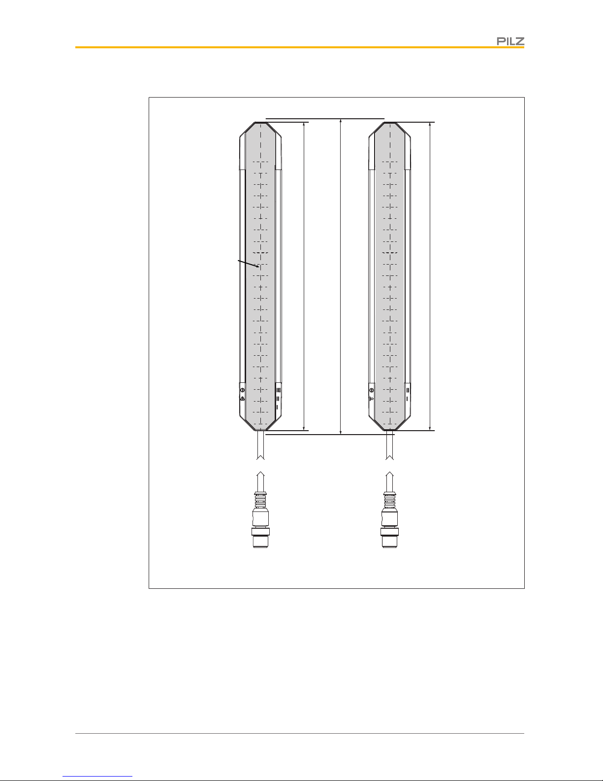
Fig.: Front view of the safety light grid transmitter and receiver, protected field height 300-1800 mm
with connection cable
Legende
[1] Protected field height
[2] Effective protected field height
[3] Tinted front panel
[4] LEDs for status information
PSEN opII3F Series
Operating Manual PSEN opII3F Series
1003504-EN-01
9
[5] Connection cable, M12 connector
[6] Optical centre axis
[5]
[3]
[1]
[4] [4] [4] [4]
[5]
[3]
[7]
[6]
[2]
[1]
Receiver Transmitter
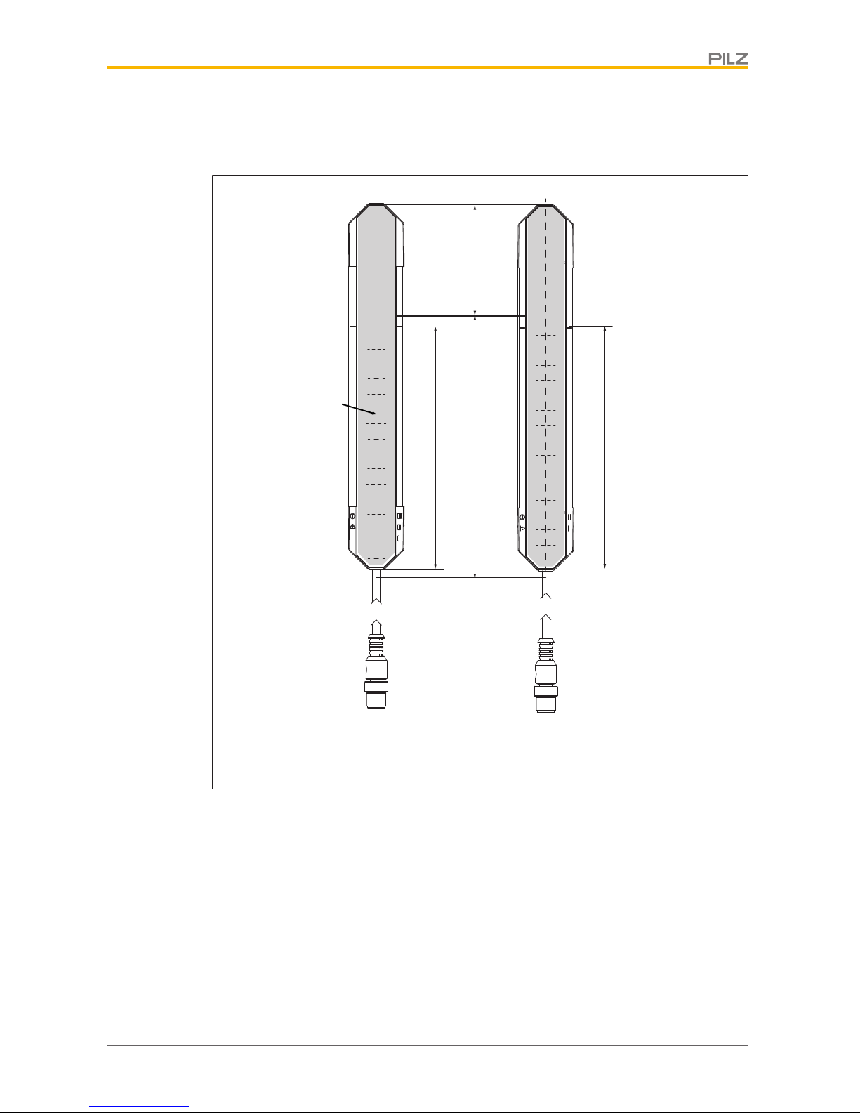
Fig.: Front view of the safety light grid transmitter and receiver, protected field height 150 mm with
connection cable
Legende
[1] Protected field height
[2] Effective protected field height
[3] Tinted front panel
[4] LEDs for status information
[5] Connection cable, M12 connector
[6] Optical centre axis
PSEN opII3F Series
Operating Manual PSEN opII3F Series
1003504-EN-01
10
[7] Dead zone
The beginning of the dead zone is indicated by black lines on both sides of the
front panel
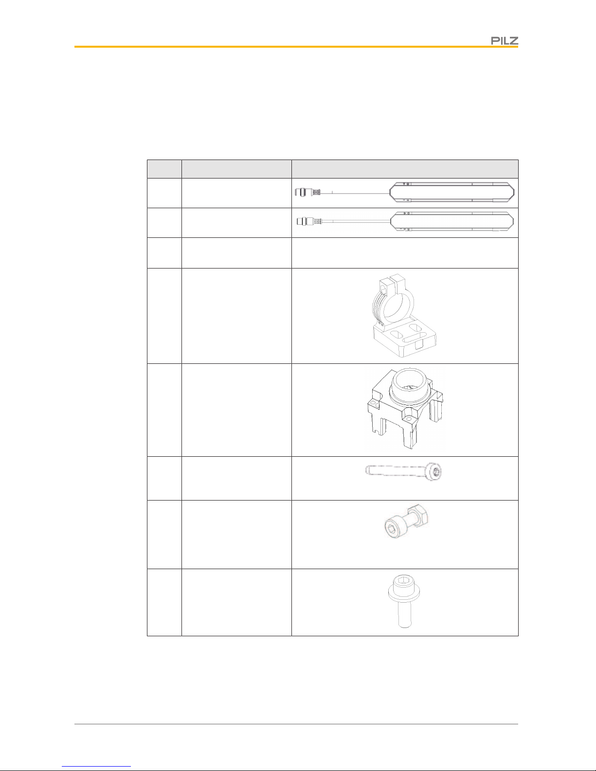
Scope
Qty Description Diagram
1 Transmitter
1 Receiver
4 Standard installation kit
consisting of:
4
} Flexible bracket
(swivel mount) in
which transmitters/receivers can be
fastened and rotated
to the proper orientation
4
} Holder for connecting
the transmitter/receiver end caps to
the flexible bracket
16
} Tightening screw
M3x33.4 oval-head
screw, self-tapping
4
} Clamping screw with
nut
ISO4762 M4x10 8.8
cylinder screw with
nut
8
} Mounting screw
ISO4762 M6x20 8.8
cylinder screw with
washer

PSEN opII3F Series
Operating Manual PSEN opII3F Series
1003504-EN-01
11
Safety
Intended use
Safety light grids of the PSEN opII3F Series are electrosensitive protective equipment of
the 3. They are used to protect personnel and systems. The safety light grids are designed
for
} securing hazardous areas within buildings and
} securing access within buildings with a resolution of 14 mm.
The safety light grid may only be used for personal protection on machinery if
} the hazardous state can be removed by the safety light grid and
} the starting of the machine is controlled by the safety light grid and
} the safety assessment prescribes no better resolution than 14 mm.
The safety level PL d (Cat. 3 )/SIL CL 2 is only achieved if
} the safety outputs use 2-channel processing.
The safety light grid is not equipped with a restart interlock.
If the safety assessment necessitates a restart interlock, this feature must be ensured
within the plant’s programmable safety system. The system may not be started in the hazardous area following a protection violation if personnel are still in the hazardous area.
Prevent circumvention of the protected field. This means that other safety devices and safeguards may be required in addition to the safety light grid. These should be determined via
a safety assessment based on the specific application area and specific local conditions
(e.g. official specifications).
Refer to IEC/TS 62046 to determine other necessary safeguards for securing the hazardous area.
Their application must fulfil the site’s relevant national regulations (e.g.EN60204-1,
NFPA79:17-7).
The following is deemed improper use in particular:
} Any component, technical or electrical modification to the product
} Use of the product outside the areas described in this manual
} Use of the product outside the technical details (see Technical details [ 42]).
NOTICE
EMC-compliant electrical installation
The product is designed for use in an industrial environment. The product
may cause interference if installed in other environments. If installed in other
environments, measures should be taken to comply with the applicable
standards and directives for the respective installation site with regard to interference.

PSEN opII3F Series
Operating Manual PSEN opII3F Series
1003504-EN-01
12
Safety regulations
Safety assessment
Before using a unit it is necessary to perform a safety assessment in accordance with the
Machinery Directive.
Functional safety is guaranteed for the product as a single component. However, this does
not guarantee the functional safety of the overall plant/machine. In order to achieve the required safety level for the overall plant/machine, define the safety requirements for the
plant/machine and then define how these must be implemented from a technical and organisational standpoint.
Use of qualified personnel
The products may only be assembled, installed, programmed, commissioned, operated,
maintained and decommissioned by competent persons.
A competent person is someone who, because of their training, experience and current professional activity, has the specialist knowledge required to test, assess and operate the
work equipment, devices, systems, plant and machinery in accordance with the general
standards and guidelines for safety technology.
It is the company’s responsibility only to employ personnel who:
} Are familiar with the basic regulations concerning health and safety / accident preven-
tion
} Have read and understood the information provided in this description under "Safety"
} And have a good knowledge of the generic and specialist standards applicable to the
specific application.
Warranty and liability
All claims to warranty and liability will be rendered invalid if
} The product was used contrary to the purpose for which it is intended
} Damage can be attributed to not having followed the guidelines in the manual
} Operating personnel are not suitably qualified
} Any type of modification has been made (e.g. exchanging components on the PCB
boards, soldering work etc.).
Disposal
} In safety-related applications, please comply with the mission time TM in the safety-re-
lated characteristic data.
} When decommissioning, please comply with local regulations regarding the disposal of
electronic devices (e.g. Electrical and Electronic Equipment Act).

PSEN opII3F Series
Operating Manual PSEN opII3F Series
1003504-EN-01
13
Function description
Basic function
The safety light grid consists of a transmitter and a receiver.
Their shape and design
} protect the transmitter and receiver from external damage
} protect the safety light grid from malfunctions caused by vibration (see Technical de-
tails, environmental data section [ 42]).
The protected area is covered by infrared light beams, which are emitted from the transmitter to the receiver. The protected field thus produced is able to detect an opaque object.
The control and monitoring of the transmitted and received infrared rays is performed by
microprocessors.
The output signal switching devices (OSSDs) switch to the OFF state when one of the following conditions is met:
} one or more light beams are interrupted by an object, a body part, or an opaque object
that is at least as large as the resolution (14 mm) covered by the safety light grid,
} an error is detected by one of the OSSDs,
} or interfering light is detected.
If an error occurs, the OSSDs remain in the OFF state. The state can be returned to the ON
state only after a successful restart [ 38] of the safety light grid.
The safety light grid of the PSEN opII3F Series offers the following functions:
} automatic start
} automatic restart
} Operation of 2 safety light grids that are parallel to one another and are installed with
the same orientation (noting the information in ambient conditions [ 20] and min-
imum separation of parallel, aligned safety light grids [ 20])
Transmitters and receivers are each electrically connected with a cable with an M12 connector that is assigned to the transmitter and receiver on the LED side.
The transmitter and receiver are optically synchronised and therefore need not be directly
connected to each other.
Information about the operating status of the safety light grid and any error state is provided
by means of LEDs.
The indicators are described in the Status Information [ 35] section.
Automatic start and restart
Automatic start
During safety light grid commissioning, the safety light grid starts automatically, and the
OSSDs switch to the ON state under the following conditions:
} both OSSDs are wired correctly and
} no error has occurred and
} the protected field is clear.
If the protected field is violated, the OSSDs switch to the OFF state.
PSEN opII3F Series
Operating Manual PSEN opII3F Series
1003504-EN-01
14
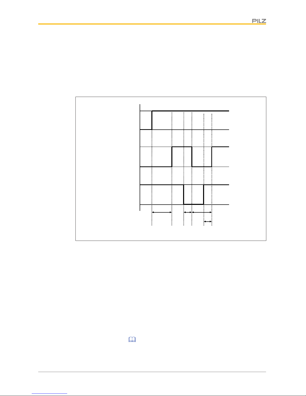
Automatic restart
The OSSDs automatically switch to the ON state during operation under the following conditions:
} both OSSDs are wired correctly and
} no error has occurred and
} the protected field is clear and
} at least 80 ms have elapsed since the switch to the OFF state.
[1] [2] [3] [4] [5]
POWER
OSSD
2 3
4
[6]
t
1
tt
t
Protected
field
Free
Interrupted
ON
OFF
ON
OFF
Fig.: Automatic start and restart timing diagram
Legende
[1] Safety light grid is switched on
[2] Check completed successfully, OSSDs in the ON state
[3] Protected field broken
[4] OSSDs in the OFF state
[5] Protected field is clear again, check for errors is restarted
[6] OSSDs in the ON state
t
1
Check is begun to determine whether the protected field is clear and whether
there are errors
t
2
Response time required for the OSSDs to switch to the OFF state (see Tech-
nical details [ 42])
t
3
Minimum time that the OSSDs remain in the OFF state: 80ms

PSEN opII3F Series
Operating Manual PSEN opII3F Series
1003504-EN-01
15
t
4
Interval between enabling of the protected field and the OSSD’s change to the
ON state
} If a synchronisation beam pair is interrupted: Response time+10ms
} If both synchronisation beam pairs (first and last light beam pair) are inter-
rupted: typically600ms (no more than4s)
Project configuration
Maintaining the safety distance
The minimum distance between the safety light grid and the hazardous machine component should be such that the operator cannot reach the hazardous area until the hazardous
machine part has come to a standstill.
In accordance with the standard
} ENISO13855
this distance depends on three factors:
} Response time of the safety light grid
Interval between interruption of the beams and the OSSD’s change to the OFF state
} Machine's stopping time
Interval between the change of the OSSD to the OFF state and the stopping of the hazardous machine movement (including the reaction time of the connected relay)
} Approach speed
The speed with which the object to be detected is nearing the hazardous area in mm/s
The general formula for calculating the minimum distance in accordance with
ENISO13855 is as follows:
S = K * (t1 + t2) + C
S Minimum distance in mm, measured from the start of the protected field to the
danger source
K Approach speed with which the object to be detected is nearing the hazardous area
in mm/s
K = 1600 mm/s when S > 500 mm
K = 2000 mm/s when S ≤ 500 mm
t1Response time of the safety light grid in seconds
Time it takes for the signal at the OSSD output on the safety light grid to change
once a protected field has been violated
t2Machine's stopping time in seconds
The time required for the machine to stop after the signal at the OSSD output
changes
C Additional distance of 0 mm for safety light grids with finger protection

PSEN opII3F Series
Operating Manual PSEN opII3F Series
1003504-EN-01
16
Resolution
The safety light grids may only be used for protected fields in which a detection capability of
14 mm is sufficient.
Protected field perimeters
During planning, ensure sufficient protected field height to secure the hazardous area.
The protected field perimeter is defined in dimensions [ 40].
Ambient conditions
} Install the safety light grids in an environment that corresponds to the environmental
data provided in the Technical details [ 42].
} Do not install the safety light grid near particularly intense and/or flashing light sources;
this applies to the receiver in particular.
} The transmitter of one safety light grid must not interfere with the receiver of another
safety light grid.
} The transmitters and receivers of two different safety light grids must not be synchron-
ised.
} Avoid strong electromagnetic interference when operating the safety light grid.
} When operating the safety light grid, avoid the development of smoke, mist, or dust that
would reduce the grid’s operating range.
PSEN opII3F Series
Operating Manual PSEN opII3F Series
1003504-EN-01
17
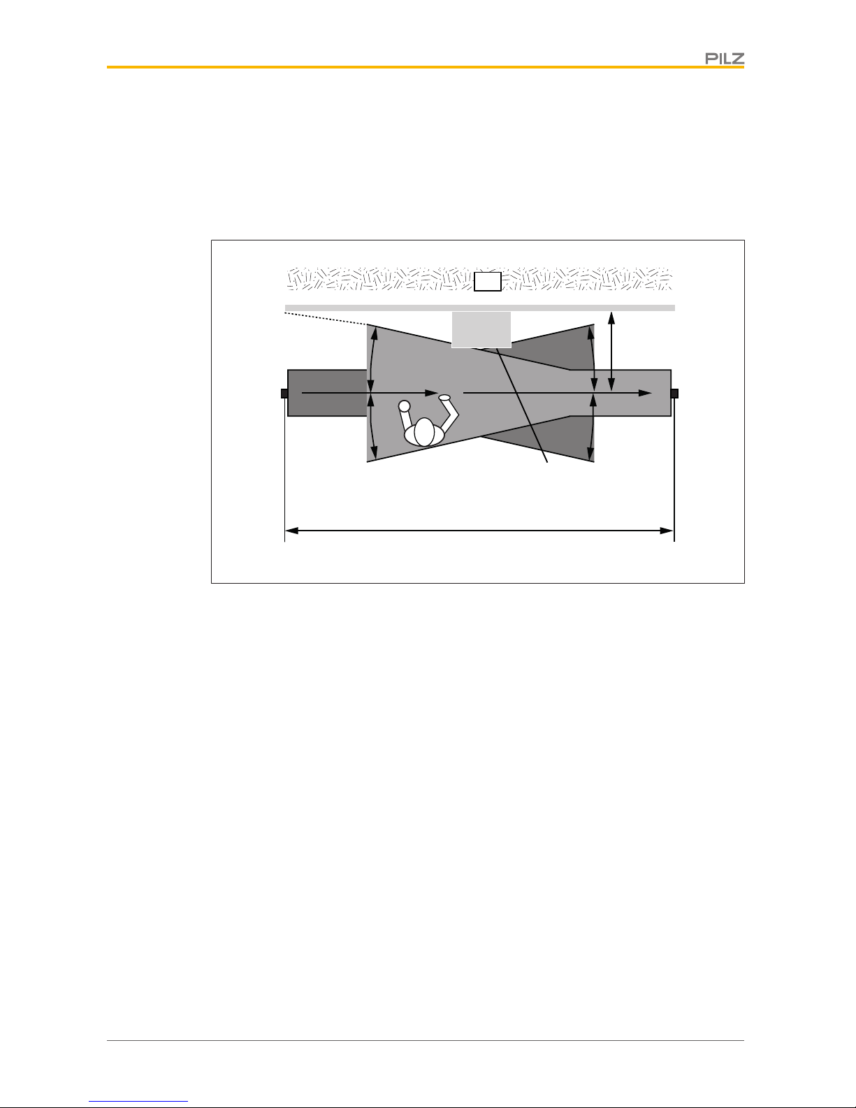
Distance from reflective surfaces
If there are reflective surfaces near the beams emitted from the safety light grid (whether
from above, below, or from the side), passive reflections can cause an object within the protected field to remain undetected (see diagrams).
This means that there must be a certain minimum distance between the safety light grid
and reflective surfaces.
[1]
[2]
[3]
[5]
[6]
[4]
[4] [4]
[4]
[7]
[8]
Fig.: Interference with the function of the safety light grid due to reflective surfaces – top view

PSEN opII3F Series
Operating Manual PSEN opII3F Series
1003504-EN-01
18
[1]
[2] [3]
[4]
[4]
[4]
[4]
[5]
[1]
[5]
Legend
[1] Reflective surface
[2] Transmitter
[3] Receiver
[4] Half of the opening angle [ 42] (= ⍺) of the light beams emitted by the safety
light grid
[5] Minimum distance D between the safety light grid and the reflective surface
[6] Passive reflections on the surface
[7] Distance between transmitter and receiver (working distance)
[8] Hazardous area
The minimum distance D depends on two factors:
} Working distance between transmitter and receiver
} the maximum opening angle [ 42] of the light beams emitted by the safety light grid
at:
5° = ± 2.5° in relation to the optical axis
 Loading...