

Page 1

Operating Manual PMCprimo C
Operating Manual PMCprimo C
PMCprimo C
Motion Controller
Operating Manual — No. 1002242-EN-01
Page 2

This document is a translation of the original document.
All rights to this documentation are reserved by Pilz GmbH & Co. KG. Copies may be made
for internal purposes.
Suggestions and comments for improving this documentation will be gratefully received.
Pilz®, PIT®, PMI®, PNOZ®, Primo®, PSEN®, PSS®, PVIS®, SafetyBUS p®, SafetyEYE®,
SafetyNET p®, the spirit of safety® are registered and protected trademarks of
Pilz GmbH & Co. KG in some countries.
SD means Secure Digital.
Preface
Page 3

Contents
Contents
Contents Page
Chapter 1 Introduction
1.1 Validity of the documentation 1-1
1.1.1 Retaining the documentation 1-1
1.2 Overview of documentation 1-2
1.3 Definition of symbols 1-3
Chapter 2 Overview
2.1 Unit features 2-1
2.2 Front view 2-2
2.3 Type code 2-3
2.4 Scope of supply 2-4
Chapter 3 Security
3.1 Intended use 3-1
3.2 Safety regulations 3-2
3.2.1 Use of qualified personnel 3-2
3.2.2 Warranty and liability 3-2
3.2.3 Disposal 3-2
3.3 Standards 3-3
Chapter 4 Function description
4.1 Device properties 4-1
4.1.1 Controller 4-1
4.1.2 Supply voltage 4-2
4.1.3 Digital inputs 4-3
4.1.4 Digital outputs 4-3
4.1.5 Interfaces 4-3
4.1.5.1 Overview 4-3
4.1.5.2 CANopen 4-5
4.1.5.3 PROFIBUS DP 4-6
4.1.5.4 Ethernet 4-6
4.1.5.5 SafetyNET p (in preparation) 4-7
4.1.6 Encoder 4-7
4.1.7 Reset button 4-8
4.2 Software 4-9
Chapter 5 Installation
5.1 General requirements 5-1
5.2 Dimensions 5-2
5.3 Installing the unit 5-3
5.4 Installing the fieldbus junction box 5-4
Pilz GmbH & Co. KG, Felix-Wankel-Straße 2, 73760 Ostfildern, Germany
Telephone: +49 711 3409-0, Telefax: +49 711 3409-133, E-Mail: pilz.gmbh@pilz.de
1
Page 4

Contents
Chapter 6 Wiring
6.1 Wiring guidelines 6-1
6.2 Connector pin assignment X40 6-2
6.3 Supply voltage 6-3
6.4 Digital inputs 6-4
6.5 Digital outputs 6-5
6.6 Interfaces 6-6
6.6.1 Overview 6-6
6.6.2 CANopen, PROFIBUS DP 6-6
6.6.2.1 Wiring guidelines for the CANopen inter-
6.6.2.2 Two CANopen interfaces 6-8
6.6.2.3 CANopen/PROFIBUS DP interface 6-8
6.6.3 Ethernet 6-9
6.6.4 SafetyNET p (in preparation) 6-9
6.7 Encoder 6-10
6.7.1 Supply voltage 6-10
6.7.2 Incremental encoder with TTL signal 6-11
6.7.3 Absolute encoder with SSI interface 6-12
6-6
face
Chapter 7 Commissioning
7.1 Safety guidelines 7-1
7.2 Commissioning the PMCprimo C 7-2
7.2.1 Preparing for commissioning 7-2
7.2.2 Establish communication PMCprimo C <> PC
7.2.3 Adapt basic configuration of PMCprimo 7-7
7.2.4 Configure servo amplifier 7-8
7.2.5 Operate PMCprimo C 7-9
7.3 Install CoDeSys 7-12
Chapter 8 Operation
8.1 Operating states and changes in operating
status
8.1.1 Status graph 8-1
8.1.2 Operating states 8-2
8.1.2.1 "Power Off" operating status 8-2
8.1.2.2 "Startup" operating status 8-2
8.1.2.3 "Boot Menu" operating status 8-2
8.1.2.4 "RUN" operating status 8-3
8.1.2.5 "STOP" operating status 8-3
8.1.2.6 "Fatal Error" operating status 8-3
8.1.3 Change in operating status 8-4
8.2 Reset, restart, start and stop options 8-7
8.2.1 Overview 8-7
7-3
8-1
Pilz GmbH & Co. KG, Felix-Wankel-Straße 2, 73760 Ostfildern, Germany
2
Telephone: +49 711 3409-0, Telefax: +49 711 3409-133, E-Mail: pilz.gmbh@pilz.de
Page 5

Contents
8.2.2 Cold start, "Startup" 8-7
8.2.3 Reset commands 8-8
8.2.3.1 Warm reset 8-8
8.2.3.2 Cold reset 8-8
8.2.3.3 Original Reset 8-8
8.2.4 Start and stop commands 8-9
8.3 Functions of the reset button 8-10
8.4 Messages 8-11
8.5 Display elements 8-12
Chapter 9 Technical details
Pilz GmbH & Co. KG, Felix-Wankel-Straße 2, 73760 Ostfildern, Germany
Telephone: +49 711 3409-0, Telefax: +49 711 3409-133, E-Mail: pilz.gmbh@pilz.de
3
Page 6

Contents
Pilz GmbH & Co. KG, Felix-Wankel-Straße 2, 73760 Ostfildern, Germany
4
Telephone: +49 711 3409-0, Telefax: +49 711 3409-133, E-Mail: pilz.gmbh@pilz.de
Page 7

1 Introduction
1.1 Validity of the documentation
11000IntroductionIntroduction1-1.1Validity of the documentation1100Validity of th e documentation1-Einf Gltigkeit der Dokumentation
This documentation is valid for the product PMCprimo C. It is valid until
][BA_Einfhrung_Einleitung
Einf_Dokumente
new documentation is published.
This operating manual explains the function and operation, describes
the installation and provides guidelines on how to connect the product
PMCprimo C.
Please also refer to the following documents from the motion control
range:
The online help for the PDrive commissioning software describes how
to set the parameters for the servo amplifiers from the PMC product
area.
Guidelines regarding installation and environmental conditions can be
found in the operating manual for the servo amplifier PMCprotego D.
The configuration and programming software for motion control de-
vices (e.g. CoDeSys, PTerm, PScope, PMotion) can be found on the
CD-ROM "Motion Control Tools".
The manuals for Pilz products from the PMC product area are availa-
ble on the supplied CD-ROM "Documentation Motion Control".
You will need to be conversant with the information in these documents
in order to fully understand this manual.
1.1.1 Retaining the documentation
Retaining the documentation1-Einf Aufbewahren
This documentation is intended for instruction and should be retained
for future reference.
Pilz GmbH & Co. KG, Felix-Wankel-Straße 2, 73760 Ostfildern, Germany
Telephone: +49 711 3409-0, Telefax: +49 711 3409-133, E-Mail: pilz.gmbh@pilz.de
1-1
Page 8

1 Introduction
1.2 Overview of documentation
1.2Overview of documentation1200Overview of documentation1-Einf_Uebersicht_Doku
1 Introduction
The introduction is designed to familiarise you with the contents, structure and specific order of this manual.
2 Overview
This chapter provides information on the product's most important features.
3 Safety
This chapter must be read as it contains important information on safety
and intended use.
4 Function Description
This chapter describes the product's individual functions.
5 Installation
This chapter explains how to install the product.
6 Wiring
This chapter describes the product's wiring.
7 Commissioning
This chapter describes how to commission the product.
8 Operation
This chapter describes the display elements, explaining their operation
and diagnostics.
1-2
9 Technical Details
Pilz GmbH & Co. KG, Felix-Wankel-Straße 2, 73760 Ostfildern, Germany
Telephone: +49 711 3409-0, Telefax: +49 711 3409-133, E-Mail: pilz.gmbh@pilz.de
Page 9
1 Introduction
1.3 Definition of symbols
1.3Definition of symbols1300Definition of symbols1-Einfhrung Zeichen
Information that is particularly important is identified as follows:
DANGER!
This warning must be heeded! It warns of a hazardous situation
that poses an immediate threat of serious injury and death and
indicates preventive measures that can be taken.
WARNING!
This warning must be heeded! It warns of a hazardous situation
that could lead to serious injury and death and indicates preventive measures that can be taken.
CAUTION!
This refers to a hazard that can lead to a less serious or minor
injury plus material damage, and also provides information on
preventive measures that can be taken.
NOTICE
This describes a situation in which the unit(s) could be damaged
and also provides information on preventive measures that can
be taken. It also highlights areas within the text that are of particular importance.
INFORMATION
This gives advice on applications and provides information on
special features.
Pilz GmbH & Co. KG, Felix-Wankel-Straße 2, 73760 Ostfildern, Germany
Telephone: +49 711 3409-0, Telefax: +49 711 3409-133, E-Mail: pilz.gmbh@pilz.de
1-3
Page 10

1 Introduction
1-4
Pilz GmbH & Co. KG, Felix-Wankel-Straße 2, 73760 Ostfildern, Germany
Telephone: +49 711 3409-0, Telefax: +49 711 3409-133, E-Mail: pilz.gmbh@pilz.de
Page 11

2 Overview
2.1 Unit features
22000OverviewOverview2-2.1Unit features2100Unit features2-Uebersicht_System_PMCprimo_C
PMCprimo C is a motion controller used to automate multi-axis motion
sequences. The device contains a PLC with the functionality of a logic
and motion controller.
Logic controller universally programmable in accordance with
IEC 61131-3
Motion controller
– Speed axes
– Positioning axes
– Synchronisation axes (electrical cam disk)
– Path axes (interpolation)
– Technological functions
Digital inputs and outputs
– 6 digital inputs, each one can be used as a quick reference input
– 6 single-pole digital outputs
Encoder
– Incremental encoder with TTL signal
– Absolute encoder with SSI interface
Interfaces
– Ethernet TCP/IP
– SafetyNET p RTFN (in preparation)
– SafetyNET p RTFL (in preparation)
Depends on unit type
– 2 CANopen interfaces
– 1 CANopen/ 1 PROFIBUS DP interface
Supply voltages for
– Device plus digital outputs
–Encoder
Memory for
– Operating system
–Data
– Device project with user program
Reset button
– To change between operating states
– For a hardware reset (cold start)
LED display for device's operating status
Pilz GmbH & Co. KG, Felix-Wankel-Straße 2, 73760 Ostfildern, Germany
Telephone: +49 711 3409-0, Telefax: +49 711 3409-133, E-Mail: pilz.gmbh@pilz.de
2-1
Page 12
2 Overview
1
2
3
4
5
6
7
8
9
10
11
12
13
14
15
16
STAT
RESET
680050 12
100001
X45
X44
X43
X42
X41
X40
1
3
4
5
6
2
7
10
1
4
8
9
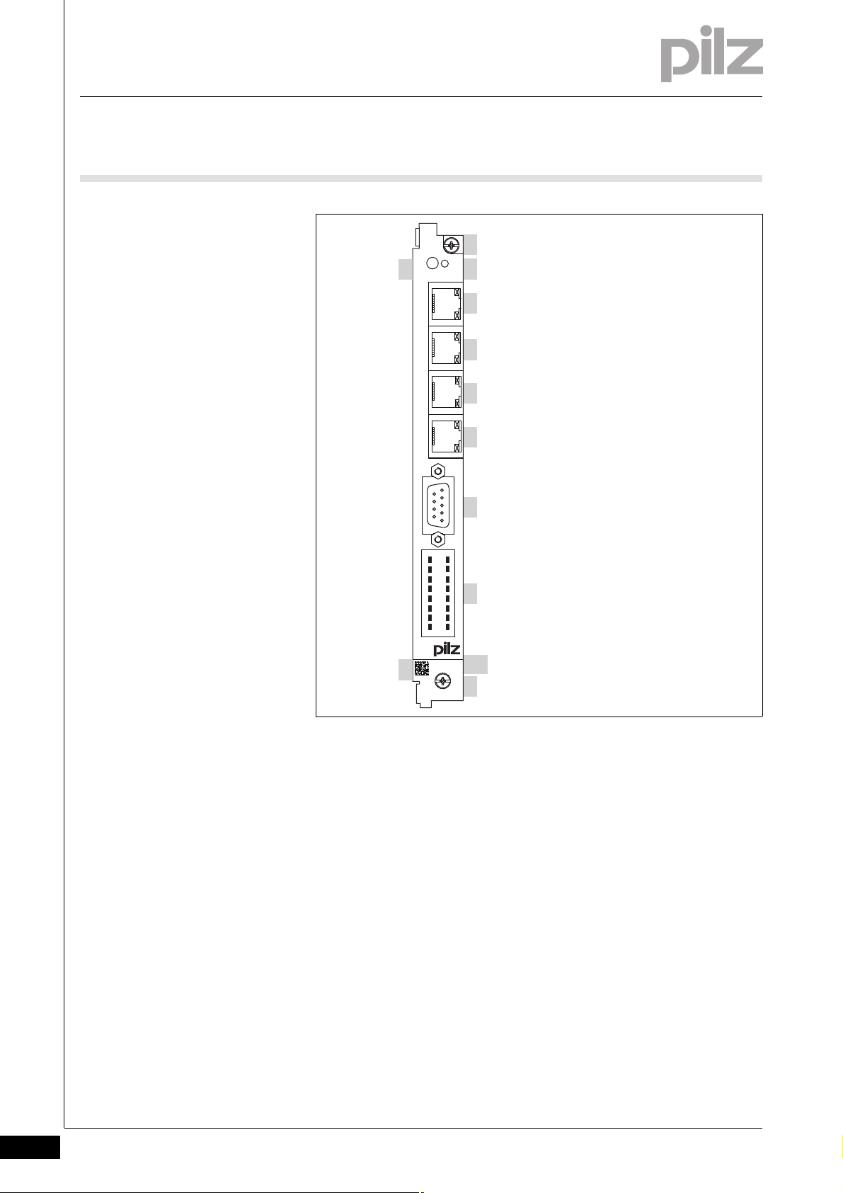
2.2 Front view
2.2Front view2200Front view2-Übersicht_Front
Uebersicht_Front_Legende
Legend:
1: Screw for attachment to the servo amplifier
2: Reset button
3: LED to display operating states
4: SafetyNET p RTFL interface
5: SafetyNET p RTFN/Ethernet TCP/IP interface
6: CANopen/PROFIBUS DP interface
7: Connection for encoder
8: Digital inputs/outputs and supply voltages
9: 2D code
10: Labelling strip with:
– Order number
2-2
Pilz GmbH & Co. KG, Felix-Wankel-Straße 2, 73760 Ostfildern, Germany
Telephone: +49 711 3409-0, Telefax: +49 711 3409-133, E-Mail: pilz.gmbh@pilz.de
– Serial number
– Number of device version
Page 13
2 Overview
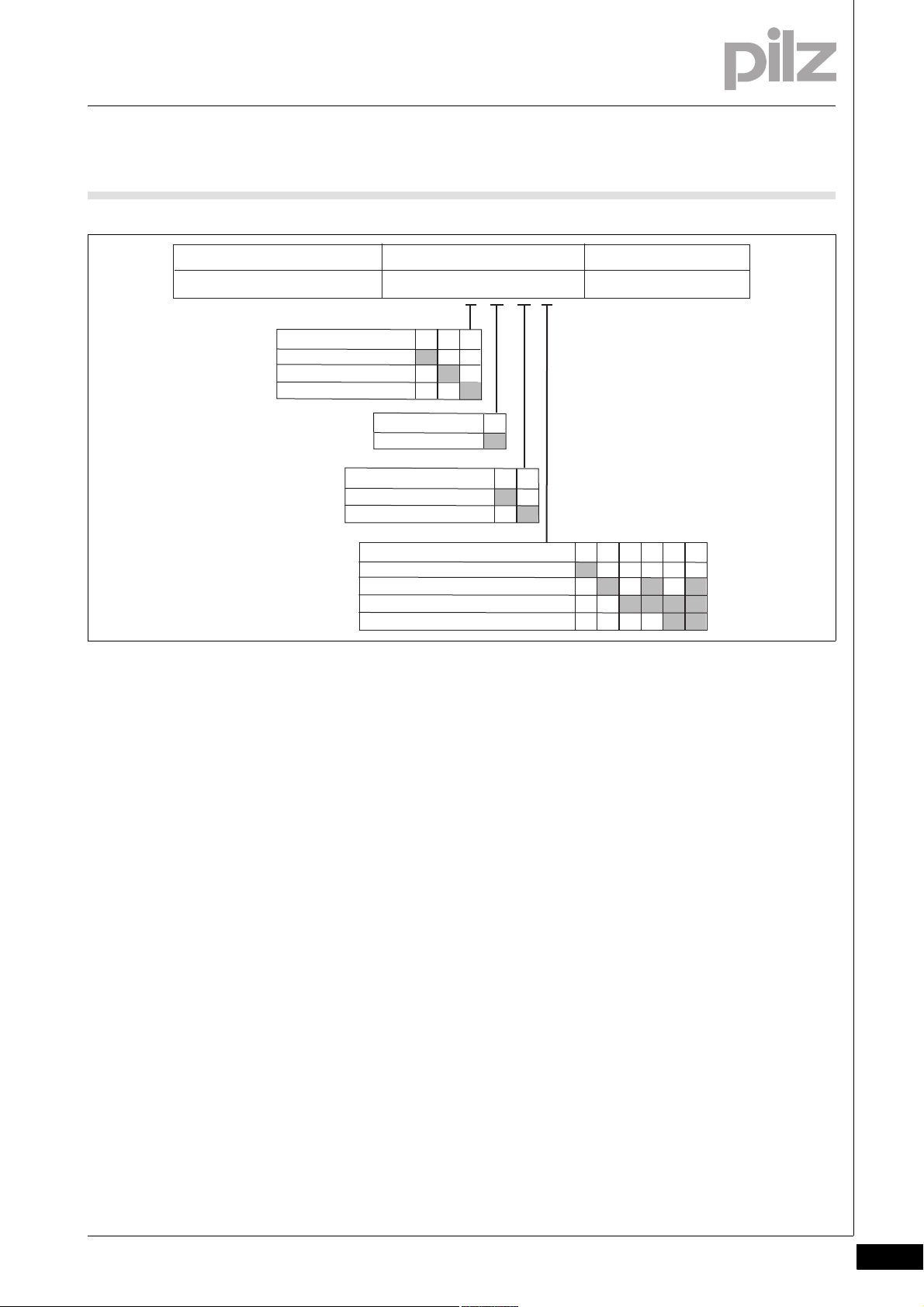
Always state when ordering Type
Supply voltage
Order number PMCprimo C. _ / _ / _ / _ 24 VDC
Hardware
CANopen/CANopen
CANopen/PROFIBUS DP
A B
CPU
0.6 GHz
A
Software
None
Dynamic curve calculation
IEC 61131-3 programming
Path interpolation
2 34567
Servo amplifier
None
PMCprotego D.01-24
PMCprotego D.48-72
012
2.3 Type code
2.3Type code2300Type code2-Typenschlüssel
Fig. 2-1: Type code for PMCprimo C
Explanation of type code
Servo amplifier
Type of servo amplifier in which the PMCprimo C is installed
CPU
Clock frequency of processor
Hardware
– A: Two CANopen interfaces
– B: One CANopen and one PROFIBUS DP Slave interface
Software
– 2: Software options not enabled
– 3, 5, 7: Dynamic curve calculation enabled
The dynamic curve calculation is a calculation program for allocation tables. The allocation table is defined through variables and
scaling. The dynamic curve calculation reads in the variables and
calculates an allocation table.
– 4-7: IEC 61231-3 programming enabled
PLC functionality is programmed with CoDeSys.
– 6, 7: Path interpolation enabled
PLC functionality and path interpolation
Pilz GmbH & Co. KG, Felix-Wankel-Straße 2, 73760 Ostfildern, Germany
Telephone: +49 711 3409-0, Telefax: +49 711 3409-133, E-Mail: pilz.gmbh@pilz.de
2-3
Page 14

2 Overview
2.4 Scope of supply
2.4Scope of supply2400Scope of supply2-Lieferumfang
Order reference Description Order number
PMCprimo C Expansion card for motion controller (for
function range see "Type code")
PMCprotego D.CAN-CANbus Adapter 0124A incl. RJ45 connection cable
PMCprotego D.CAN-CANbus Adapter 4872A incl. RJ45 connection cable
PMCprotego D.CAN-PROFIBUS Adapter
01-24A incl. RJ45 connection cable
PMCprotego D.CAN-PROFIBUS Adapter
48-72A incl. RJ45 connection cable
CD-ROM "Documentation Motion Control" Operating manual PMCprimo C,
Fieldbus junction box with two CANopen
interfaces for PMCprotego D.01 … D.24
Fieldbus junction box with two CANopen
interfaces for PMCprotego D.48/D.72
Fieldbus juction box with one CANopen interface and one PROFIBUS interface for
PMCprotego D.01 … D.24
Fieldbus juction box with one CANopen interface and one PROFIBUS interface for
PMCprotego D.48/D.72
Manuals for Pilz products from the PMC
product area
See "Type code"
680040
680042
680041
680043
---
2-4
Pilz GmbH & Co. KG, Felix-Wankel-Straße 2, 73760 Ostfildern, Germany
Telephone: +49 711 3409-0, Telefax: +49 711 3409-133, E-Mail: pilz.gmbh@pilz.de
Page 15

3 Security
3.1 Intended use
33000SecuritySecurity3-3.1Intended use3100Intended use3-BA_Sicherh eit_Bestimmung
The motion controller PMCprimo C is suitable for use in logic and motion control applications.
Examples of typical application areas for the product are
Clocked production machinery
Continuous manufacturing processes (winding, flying saw, cross cut-
ter)
Machine tools
Packaging machines
Pick and place applications
The motion controller is installed in the servo amplifier PMCprotego D.
Once installed, the environmental conditions of the servo amplifier PMCprotego D apply, e.g. the lower storage temperature (see "Technical
Details" in the operating manual for the servo amplifier).
Bestimmung/Gerätebeschreibung_EMV+Ausschluss
Please note that the PMCprimo C has no internal electrical connection
to the servo amplifier PMCprotego D. When installing and operating the
device, you must refer to the operating manuals for the servo amplifiers,
in particular the safety guidelines.
Intended use includes making the electrical installation EMC-compliant.
The product is designed for use in an industrial environment. It is not
suitable for use in a domestic environment, as this can lead to interference.
The following is deemed improper use in particular:
Any component, technical or electrical modification to the product
Use of the product outside the areas described in this manual
Use of the product outside the technical details (see chapter entitled
“Technical Details”)
Pilz GmbH & Co. KG, Felix-Wankel-Straße 2, 73760 Ostfildern, Germany
Telephone: +49 711 3409-0, Telefax: +49 711 3409-133, E-Mail: pilz.gmbh@pilz.de
3-1
Page 16

3 Security
3.2 Safety regulations
3.2Safety regulations3200Safety regulations3-
3.2.1 Use of qualified personnel
Use of qualified personnel3-Sich Qualif. Personal
The products may only be assembled, installed, programmed, commissioned, operated, maintained and decommissioned by competent persons.
A competent person is someone who, because of their training, experience and current professional activity, has the specialist knowledge required to test, assess and operate the work equipment, devices,
systems, plant and machinery in accordance with the general standards
and guidelines for safety technology.
It is the company's responsibility only to employ personnel who:
Are familiar with the basic regulations concerning health and safety /
accident prevention
Have read and understood the safety guidelines given in this descrip-
tion
Have a good knowledge of the generic and specialist standards ap-
plicable to the specific application.
3.2.2 Warranty and liability
Warranty and liability3-Sich Gewhrleistung
3.2.3 Disposal
Disposal3-Si ch Entsorgung nur Standard
All claims to warranty and liability will be rendered invalid if:
The product was used contrary to the purpose for which it is intended
Damage can be attributed to not having followed the guidelines in the
manual
Operating personnel are not suitably qualified
Any type of modification has been made (e.g. exchanging compo-
nents on the PCB boards, soldering work etc.).
When decommissioning, please comply with local regulations regard-
ing the disposal of electronic devices (e.g. Electrical and Electronic
Equipment Act).
3-2
Pilz GmbH & Co. KG, Felix-Wankel-Straße 2, 73760 Ostfildern, Germany
Telephone: +49 711 3409-0, Telefax: +49 711 3409-133, E-Mail: pilz.gmbh@pilz.de
Page 17

3 Security
3.3 Standards
3.3Standards3300Standards3-BA_Sicherheit_Normen
To use the device correctly you will need to have a good knowledge of
the relevant standards and directives. The following standards are relevant:
EN 61131-1:2003: Programmable controllers – Part 1: General infor-
mation
EN 61131-2:2003: Programmable controllers – Part 2: Equipment re-
quirements and tests
EN 61131-3:2003: Programmable controllers – Part 3: Programming
languages
Please note this is not an exhaustive list of safety standards and directives.
Pilz GmbH & Co. KG, Felix-Wankel-Straße 2, 73760 Ostfildern, Germany
Telephone: +49 711 3409-0, Telefax: +49 711 3409-133, E-Mail: pilz.gmbh@pilz.de
3-3
Page 18

3 Security
3-4
Pilz GmbH & Co. KG, Felix-Wankel-Straße 2, 73760 Ostfildern, Germany
Telephone: +49 711 3409-0, Telefax: +49 711 3409-133, E-Mail: pilz.gmbh@pilz.de
Page 19
4 Function description
X45
X44
X43
X42
715
Power
=
~
X40
1 2 3
Inputs
SafetyNET p
Ethernet
CANopen
PROFIBUS
9 10 11
4 5 6
12 13 14
Outputs
816
Power
Encoder
Logic
Motion Control
Encoder
X40
X41
STAT RE SET
4.1 Device properties
44000Function descriptionFunction description4-4.1Device properties4100Device properties4-
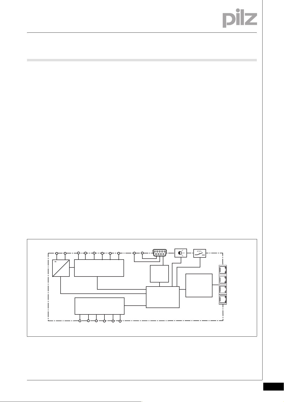
4.1.1 Controller
Controller4-Funktion_PMCprimo_C
The PMCprimo C is a drive-integrated programmable logic controller
with motion control functionalities. The controller has volatile and nonvolatile memory for the operating system, the data and the device
project with the user program.
It can be used for logic and motion control of intelligent drives.
User programs can be programmed in the main IEC 61131-3 languages.
The software CoDeSys is used to program the PLC functionality. The
controller runs as an independent task.
The motion controller has 6 digital inputs and 6 single-pole digital outputs. The inputs and outputs are read cyclically. The cycle times are ≤
1ms. It can also access inputs and outputs on networked servo amplifiers from the PMC product area.
Funktion_PMCprimo_C_Blockschaltbild
The motion controller has fieldbus interfaces for communication with the
periphery.
An additional encoder can be connected (incremental encoder with TTL
signal or absolute encoder with SSI interface).
An LED provides information about the controller's operating states.
Funktion_PMCprimo_C_Umfeld
Pilz GmbH & Co. KG, Felix-Wankel-Straße 2, 73760 Ostfildern, Germany
Telephone: +49 711 3409-0, Telefax: +49 711 3409-133, E-Mail: pilz.gmbh@pilz.de
Fig. 4-1: Block diagram PMCprimo C
4-1
Page 20
4 Function description
1
2
3
4
5
6
7
8
9
10
11
12
13
14
15
16
START
RESET
680050 12
100001
X45
X44
X43
X42
X41
X40
X42
X6B
CANopen 1
CANopen 2
PROFIBUS DP
X6C
1
1
Ethernet
X43
3
2
4.1 Device properties
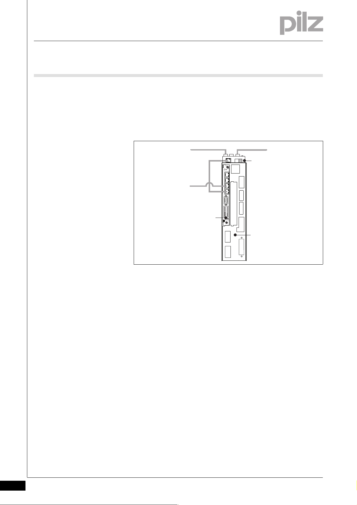
The motion controller PMCprimo C (1) is installed in a servo amplifier
PMCprotego D (3). A fieldbus junction box PMCprotego D.CAN-CANbus Adapter or PMCprotego D.CAN-PROFIBUS Adapter (2) is used for
networking (CANopen, PROFIBUS DP).
4.1.2 Supply voltage
Supply voltage4-Funktion_Versorgung
Fig. 4-2: Installation of the motion controller in a servo amplifier PM-
Cprotego D
The PMCprimo C has two supply voltages:
X40/7,15
Supply voltage for the device and the digital outputs (24 VDC)
X40/8,16
Supply voltage for the encoder (5 V, 24 VDC)
The voltage is connected directly to the female 9-pin D-Sub connec-
tor X41/4,9.
Internally the two supply voltages are galvanically isolated. The two
earths can be connected externally.
4-2
Pilz GmbH & Co. KG, Felix-Wankel-Straße 2, 73760 Ostfildern, Germany
Telephone: +49 711 3409-0, Telefax: +49 711 3409-133, E-Mail: pilz.gmbh@pilz.de
Page 21

4 Function description
4.1 Device properties
4.1.3 Digital inputs
Digital inputs4-Funktion_Eingaenge
The device has 6 digital inputs.
The inputs are compatible with EN 61131-2, Type 1.
The time behaviour of the digital inputs depends on the method of use:
With normal use, the inputs have a filter time of ≤ 600 μs.
If the inputs are used as reference inputs, the reaction time to 0/1 or
1/0 pulse edges is < 5μs.
The inputs can be used as reference inputs, to poll the position of the
encoder for example.
4.1.4 Digital outputs
Digital outputs4-Funktion_Ausgaenge
4.1.5 Interfaces
Interfaces4-
The device has 6 single-pole digital outputs.
Signals at the output
"0" signal (0 V) at the output:
– Output is high impedance
– No current to the load
"1" signal (+24 V) at the output:
– Output is low impedance
– Current is supplied to the load
– The maximum current strength per output is 0.5 A.
All digital outputs are protected against short circuit and overload.
The outputs can be used to connect relays, valves or inputs from another controller, for example.
4.1.5.1 Overview
Overview4-Funktion_Schnittstellen_PMCprimo_C
The motion controller PMCprimo C has various fieldbuses for communication with the periphery. These are available on four RJ45 sockets on
the front of the device. The interfaces are suitable for the following applications:
Pilz GmbH & Co. KG, Felix-Wankel-Straße 2, 73760 Ostfildern, Germany
Telephone: +49 711 3409-0, Telefax: +49 711 3409-133, E-Mail: pilz.gmbh@pilz.de
4-3
Page 22

4 Function description
4.1 Device properties
CANopen
– Real-time capable networking between CAN devices and the mo-
tion controller
– Suitable for applications
–with (≤ 32) subscribers
– with cycle time (≥ 1ms)
– in existing networks (e.g. with PMCtendo DD5).
– Connection to the servo amplifier PMCprotego D via the fieldbus
junction box PMCprotego D.CAN-CANbus Adapter (supplied with
the device)
PROFIBUS DP Slave
– Networking between the motion controller and a PROFIBUS Mas-
ter.
– Suitable for data exchange with a third party controller.
– Connection to the servo amplifier PMCprotego D via the fieldbus
junction box PMCprotego D.CAN-PROFIBUS Adapter (supplied
with the device)
Ethernet
– Ethernet TCP/IP
– Communication between the programming device and the mo-
tion controller
– Suitable for configuration, programming, commissioning
– Modbus TCP/IP
– Communications protocol based on Industrial Ethernet (TCP/IP
over Ethernet).
– Suitable for networking between the motion controller and a vis-
ualisation device or a PSS 4000, for example.
SafetyNET p (in preparation)
– SafetyNET p RTFN
– Communication based on Standard Ethernet.
– Networking between controllers or cells and SafetyNET p RTFL
devices.
– Standard communication
– Basic topology: Star
– SafetyNET p RTFL
– Real-time capable networking between SafetyNET p RTFL de-
vices and the motion controller PMCprimo C and automation
system PSS 4000.
– The RTFL transport layer enables cycle times to be optimised,
enabling it to be used in extremely time-critical applications.
– Standard communication
– Basic topology: Linear
4-4
Pilz GmbH & Co. KG, Felix-Wankel-Straße 2, 73760 Ostfildern, Germany
Telephone: +49 711 3409-0, Telefax: +49 711 3409-133, E-Mail: pilz.gmbh@pilz.de
Page 23

4 Function description
4.1 Device properties
4.1.5.2 CANopen
CANopen4-Funktion_CANopen
The CANopen interface is suitable for networking drive components at
field level. It meets the requirements defined in the communications protocol DS-301.
The following device classes with CANopen device profiles are supported:
I/O modules DS-401
Electrical drives DS-402
Funktion_CANopen_PMCprimo_C
Encoders DS-406
The CAN network is designed as a linear structure. The CANopen communication protocol is based on CAN.
CAN networking with the motion controller is suitable for applications
with a maximum subscriber number of ≤ 32 and a cycle time ≥ 1ms.
Only CAN devices that are known to the controller or support a cor-
responding device profile can be operated in the motion controller's
CAN network.
CAN devices detected by the motion controller are ready for opera-
tion immediately after the initial network run-up. No complex configuration of the CAN devices is required.
The overall cable length and the length of the stub lines depend on the
transmission rate.
Process data objects (PDO) are defined for each CAN device type and
cannot be customised by the user.
For servo amplifiers, the "FS" command can be used to set which
process data is to be exchanged between the motion controller and
the servo amplifier (see "PMCprimo Programming Manual").
The signal lines must be terminated with resistors (120 Ohm) on the
first and last subscriber. The resistors are generally integrated within
the connected devices and can be activated there. For a
PMCprimo C, a terminating resistor can be activated in the fieldbus
junction box PMCprotego D.CAN-CANbus Adapter or
PMCprotego D.CAN-PFOFIBUS Adapter.
Pilz GmbH & Co. KG, Felix-Wankel-Straße 2, 73760 Ostfildern, Germany
Telephone: +49 711 3409-0, Telefax: +49 711 3409-133, E-Mail: pilz.gmbh@pilz.de
4-5
Page 24

4 Function description
4.1 Device properties
4.1.5.3 PROFIBUS DP
PROFIBUS DP4-Funktion_PROFIBUS
PROFIBUS is an open fieldbus standard. Communication is defined in
IEC 61158 and IEC 61784. Further provisions have been defined in
specifications published by the PROFIBUS User Group. These specifications are available from PROFIBUS International.
On a certain unit type, the PROFIBUS interface is available together with
Funktion_PROFIBUS_primo_C
a CANopen interface on an RJ45 socket (X42).
Properties:
The PROFIBUS is configured using the CD command: Slave address,
address range, see PMCprimo Programming Manual.
A total of up to 108 bus variables can be read and written (see PMCp-
rimo Programming Manual):
– Address space of bus variables: $B1 to $Bx108 (can be set using
the CD command).
– Data width: 16 Bit including sign
– Value range: -32768 to 32767 (Hex: 0x0000 to 0x7FFF).
When changing the variable content, any programs can be started if
the bus variables have been defined as trigger variables.
PROFIBUS_Hinweis_Nutzerorganisation
4.1.5.4 Ethernet
Ethernet4-Funktion_Gigabit_Ethernet
INFORMATION
The GSD file is available on the supplied CD-ROM. The name of
the description file can be found in the "Technical Details".
INFORMATION
Please also refer to the installation guidelines published by the
PROFIBUS User Group.
The Gigabit Ethernet interface (X43) connects the PMCprimo C to a pro-
gramming device for configuration, programming and commissioning.
The interface can also be used to connect a visualisation device.
The Gigabit Ethernet interface is compatible with 1000Base-T (Standard
Gigabit Ethernet). Data exchange is possible via Modbus TCP/IP.
4-6
Pilz GmbH & Co. KG, Felix-Wankel-Straße 2, 73760 Ostfildern, Germany
Telephone: +49 711 3409-0, Telefax: +49 711 3409-133, E-Mail: pilz.gmbh@pilz.de
Page 25

4 Function description
4.1 Device properties
4.1.5.5 SafetyNET p (in preparation)
SafetyNET p (in preparation)4-Funktion_SN
The components at field level are connected to the Ethernet-based multi-master bus system SafetyNET p. Higher speeds are required, so the
RTFL transport layer is used. The RTFL transport layer enables scan
times to be optimised and can therefore be used in extremely time-critical applications, such as drive controllers.
Two SafetyNET p interfaces are available for connection to a
SafetyNET p network (X44, X45).
Functions
The PMCprimo C receives signals from other network subscribers; it
processes these signals in the user program and passes them on to
the connected components.
Hinweis_PSS4000
4.1.6 Encoder
Encoder4-Funktion_Geber
MAC address
The MAC address is a factory-set default. The address can be read
with the PTerm software, using the "VN1" command
INFORMATION
Further information is available in the "System Description PSS
4000".
A rotary encoder can be connected to the 9-pin D-Sub socket X41.
The following encoder systems are supported:
Incremental encoder with TTL signal
Absolute encoder with SSI interface
The encoder's supply voltage is connected to separate terminals on the
unit (X40/8,16). The size of the voltage depends on the encoder (e.g. 5 V,
10 - 30 VDC).
INFORMATION
Refer to the chapter entitled "Wiring" for details of how to connect the supply voltage.
Pilz GmbH & Co. KG, Felix-Wankel-Straße 2, 73760 Ostfildern, Germany
Telephone: +49 711 3409-0, Telefax: +49 711 3409-133, E-Mail: pilz.gmbh@pilz.de
4-7
Page 26

4 Function description
4.1 Device properties
4.1.7 Reset button
Reset button4-Funktion_Reset_Taster
The "RESET" button is mounted in a recess on the front of the unit. It can
only be accessed using an appropriate tool (e.g. a pin).
The following actions can be triggered by pressing the "RESET" button:
Change from "Startup" operating status to "Boot Menu"
Hardware reset (cold start): Change from "RUN" or "STOP" operating
status to "Startup"
Change from "RUN" operating status to "STOP"
Change from "STOP" operating status to "RUN"
INFORMATION
Further information on the reset button can be found in the
chapter entitled "Operation".
4-8
Pilz GmbH & Co. KG, Felix-Wankel-Straße 2, 73760 Ostfildern, Germany
Telephone: +49 711 3409-0, Telefax: +49 711 3409-133, E-Mail: pilz.gmbh@pilz.de
Page 27

4 Function description
4.2 Software
4.2Software4200Software4-Uebersicht_System_PMCtools
Various tools are available for planning, configuration, programming and
commissioning. They are used to create a project:
Motion control tools
The motion control tools are a software package used to operate and
commission the motion control systems.
–Terminal program PTerm
PTerm can be used to send commands directly to the hardware. It
can also be used for firmware updates and for basic configuration
of the motion controller.
– Oscilloscope function PScope
PScope is a PC-based oscilloscope with up to 4 channels. It can
be used to record and visualise signals from controllers and servo
amplifiers.
– Elliptical curve construction PMotion
PMotion is a tool for constructing elliptical curves.
– Commissioning software PDrive
PDrive is used to parameterise and commission the servo amplifier
PMCprotego D.
CoDeSys
CoDeSys is a development environment for programming controllers
in accordance with IEC 61131-3. Additional commands for motion
Funktion_Version_CoDeSys_2.3.9
sequences have been added.
INFORMATION
For programming in accordance with IEC 61131-3 you will need
CoDeSys Version 2.3.9. This software is available on the current
CD-ROM "Motion Control Tools".
Pilz GmbH & Co. KG, Felix-Wankel-Straße 2, 73760 Ostfildern, Germany
Telephone: +49 711 3409-0, Telefax: +49 711 3409-133, E-Mail: pilz.gmbh@pilz.de
4-9
Page 28

4 Function description
4-10
Pilz GmbH & Co. KG, Felix-Wankel-Straße 2, 73760 Ostfildern, Germany
Telephone: +49 711 3409-0, Telefax: +49 711 3409-133, E-Mail: pilz.gmbh@pilz.de
Page 29

5 Installation
5.1 General requirements
55000InstallationInstallation5-5.1General requirements5100General requirements5-Montage
Montage_EMV ESD
Montage_Einbau
Please also refer to the operating manual for the servo amplifier.
CAUTION!
Damage due to electrostatic discharge!
Electrostatic discharge can damage components. Ensure
against discharge before touching the product, e.g. by touching
an earthed, conductive surface or by wearing an earthed armband.
NOTICE
The motion controller is installed in the servo amplifier
PMCprotego D. Once installed, the environmental conditions of
the servo amplifier PMCprotego D apply (see "Technical Details"
in the operating manual for the servo amplifier).
Pilz GmbH & Co. KG, Felix-Wankel-Straße 2, 73760 Ostfildern, Germany
Telephone: +49 711 3409-0, Telefax: +49 711 3409-133, E-Mail: pilz.gmbh@pilz.de
5-1
Page 30

5 Installation
18,4
(0.72'')
2,5
(0.098'')
175 (6.89'')
97,4 (3.83'')
5.2 Dimensions
5.2Dimensions5200Dime nsions5-Montage
Fig. 5-1: Dimensions, stated in mm (")
5-2
Pilz GmbH & Co. KG, Felix-Wankel-Straße 2, 73760 Ostfildern, Germany
Telephone: +49 711 3409-0, Telefax: +49 711 3409-133, E-Mail: pilz.gmbh@pilz.de
Page 31

5 Installation
PMCprotego D.01
PMCprotego D.03
PMCprotego D.06
PMCprotego D.12
PMCprotego D.24 PMCprotego D.48
PMCprotego D.72
Slot 1/2
Slot 1/2
Slot 1/2
5.3 Installing the unit
5.3Installing the unit5300Installing the unit5-Montage_primo_C
The PMCprimo C is installed in slots 1 and 2 of the servo amplifier
PMCprotego D. When installing, please note the guidelines given under
"Installation" in the operating manual for the servo amplifier.
Fig. 5-2: Slots 1 and 2 for installing the PMCprimo C
Pilz GmbH & Co. KG, Felix-Wankel-Straße 2, 73760 Ostfildern, Germany
Telephone: +49 711 3409-0, Telefax: +49 711 3409-133, E-Mail: pilz.gmbh@pilz.de
5-3
Page 32

5 Installation
START
RESET
X45
X6D
X6
5.4 Installing the fieldbus junction box
5.4Installing the fieldbus junction box5400Installing the fieldbus junction box5-Montage_Feldbusverteiler
A fieldbus junction box is included with the PMCprimo C. The fieldbus
junction box is plugged into the servo amplifier.
INFORMATION
Pin assignment, wiring and assembly are described in the operating manual for the fieldbus junction box.
To install the fieldbus junction box, follow the instructions below:
Switch off the mains voltages and 24 V supply!
Connect the 9-pin female D-Sub connector X6D to the male connec-
tor X6 on the servo amplifier.
Montage_Feldbusverteiler_Abb
Turn the screws into the thread on the housing.
5-4
Fig. 5-3: Installing the fieldbus junction box on a servo amplifier
Pilz GmbH & Co. KG, Felix-Wankel-Straße 2, 73760 Ostfildern, Germany
Telephone: +49 711 3409-0, Telefax: +49 711 3409-133, E-Mail: pilz.gmbh@pilz.de
Page 33

6 Wiring
6.1 Wiring guidelines
66000WiringWiring6-6.1Wiring guidelines6100Wiring guidelines6-Verdr_Leiterquerschnitte
Please note:
Cable cross sections for field connection terminals in mm
Verdr_Allgemein
Inputs
Appropriate wiring must be used to exclude short circuits between
Cables must be shielded if the signals are used as reference inputs.
Outputs
If short circuits occur between the cable from the output to the load
Use appropriate wiring to exclude short circuits between the outputs!
The actuators may be connected using unshielded cables.
The outputs do not need suppression for inductive loads.
2
:
– Digital inputs/outputs, supply voltage: 0.5 (AWG20) ... 1.0
(AWG18), AEH without plastic collar, in accordance with DIN
46228/1
the inputs or to a supply line!
Other signal lines do not need to be shielded.
and a supply line, it will no longer be possible to switch off the load.
Possible remedy: Use separate multicore cable for supply voltages.
Cable material
Use copper wiring.
Pilz GmbH & Co. KG, Felix-Wankel-Straße 2, 73760 Ostfildern, Germany
Telephone: +49 711 3409-0, Telefax: +49 711 3409-133, E-Mail: pilz.gmbh@pilz.de
6-1
Page 34

6 Wiring
1
2
3
4
5
6
7
8
9
10
11
12
13
14
15
16
6.2 Connector pin assignment X40
6.2Connector pin assignment X406200Connector pi n assignment X406-Verd r_primo_C_X40_Klemmenbelegung
Connector X40 Pin Designation Description
1 I1:1 Digital input 1
2 I1:2 Digital input 2
3 I1:3 Digital input 3
4 O1:1 Digital output 1
5 O1:2 Digital output 2
6 O1:3 Digital output 3
7 +24 V Supply voltage for unit and digital outputs (24
V)
8 Encoder Supply Supply voltage for encoder
9 I1:4 Digital input 4
10 I1:5 Digital input 5
11 I1:6 Digital input 6
12 O1:4 Digital output 4
13 O1:5 Digital output 5
14 O1:6 Digital output 6
15 0 V Supply Supply voltage for unit and digital outputs,
reference earth for digital inputs and outputs
(0 V)
16 0 V Encoder Supply voltage for encoder (0 V)
6-2
Pilz GmbH & Co. KG, Felix-Wankel-Straße 2, 73760 Ostfildern, Germany
Telephone: +49 711 3409-0, Telefax: +49 711 3409-133, E-Mail: pilz.gmbh@pilz.de
Page 35

6 Wiring
1
2
3
4
5
6
7
8
9
10
11
12
13
14
15
16
L3
7
X40
L1
L2
15
+24 V
0 V Supply
PE
+24 V
6.3 Supply voltage
6.3Supply voltage6300Supply voltage6-Verdr_Versorgung
Verdr_Versorgung_Warnung
The digital outputs and the unit need a 24 VDC supply.
When selecting the power supply, please refer to the requirements
stated under “Technical Details”.
The power supply must be able to bridge a power outage of 20 ms.
WARNING!
Electric shock!
Safe electrical isolation must be ensured for the external power
supply that generates the supply voltage. Failure to do so could
result in electric shock. The power supplies must comply with
EN 60950-1, 05/2006, EN 61558-2-6, 11/1997.
Verdr_primo_C_X40_Versorgung
Connector pin assignment
Connector X40 Pin Designation Description
7 +24 V Supply voltage + 24 VDC
15 0 V Supply Earth for supply voltage
Connection
24 V connection isolated from external power supply, e.g. with isolating
transformer
Noise suppression filter integrated
within the unit
Pilz GmbH & Co. KG, Felix-Wankel-Straße 2, 73760 Ostfildern, Germany
Telephone: +49 711 3409-0, Telefax: +49 711 3409-133, E-Mail: pilz.gmbh@pilz.de
6-3
Page 36

6 Wiring
1
2
3
4
5
6
7
8
9
10
11
12
13
14
15
16
1
2
3
9
0V
10
24 V
I/O-GND
X40
11
15
I1:1
I1:6
I1:5
I1:4
I1:3
I1:2
ShieldServo Drive
Shield
6.4 Digital inputs
6.4Digital inputs6400Digital inputs6-Verdr_primo_C_X40_Inputs
Connector pin assignment
Connector X40 Pin Designation Description
1 I1:1 Digital input 1
2 I1:2 Digital input 2
3 I1:3 Digital input 3
9 I1:4 Digital input 4
10 I1:5 Digital input 5
11 I1:6 Digital input 6
15 0 V Supply Reference earth for digital inputs
Connection
Input circuit Digital input
24 VDC, referenced to earth (X40/15)
Cables must be shielded if the signals are used as reference inputs.
Example: Reference inputs I1:1 and
I1:2 (Pin 1, 2)
6-4
Pilz GmbH & Co. KG, Felix-Wankel-Straße 2, 73760 Ostfildern, Germany
Telephone: +49 711 3409-0, Telefax: +49 711 3409-133, E-Mail: pilz.gmbh@pilz.de
Page 37

6 Wiring
1
2
3
4
5
6
7
8
9
10
11
12
13
14
15
16
DI 5
5
6
12
X40
DI 4
4
DI 2
DI 1
DI 3
14
O1:1
13
DI 6
O1:2
O1:3
O1:4
O1:5
O1:6
7
15
+24 V
0 V
+24 V
I/O-GND
6.5 Digital outputs
6.5Digital outputs6500Digital outputs6-Verdr_primo_C_X40_Outputs
Connector pin assignment
Connector X40 Pin Designation Description
4 O1:1 Digital output 1
5 O1:2 Digital output 2
6 O1:3 Digital output 3
7 +24 V Supply voltage for digital outputs
12 O1:4 Digital output 4
13 O1:5 Digital output 5
14 O1:6 Digital output 6
15 0 V Supply Reference earth for digital outputs
Connection
Output circuit Digital output
24 VDC, referenced to earth (X40/15)
Pilz GmbH & Co. KG, Felix-Wankel-Straße 2, 73760 Ostfildern, Germany
Telephone: +49 711 3409-0, Telefax: +49 711 3409-133, E-Mail: pilz.gmbh@pilz.de
6-5
Page 38

6 Wiring
X45
X44
X43
X42
8
1
8
1
8
1
8
1
6.6 Interfaces
6.6Interfaces6600Interfaces6-
6.6.1 Overview
Overview6-Verdr_primo_C_X42_X45_Uebersicht
Four RJ45 sockets with interfaces are available on the front.
Socket assignment
Socket X42 Connector Description
X45 SafetyNET p interface
X44 SafetyNET p interface
X43 Ethernet interface
X42 Depending on the unit type:
- 2 CANopen interfaces
- 1 CANopen/ 1 PROFIBUS DP interface
6.6.2 CANopen, PROFIBUS DP
CANopen, PROFIBUS DP6-Verdr_ primo_C_X42_Varianten
Depending on the unit type, socket X42 is assigned to
A combined CANopen/PROFIBUS DP interface
Two CANopen interfaces
6.6.2.1 Wiring guidelines for the CANopen interface
Wiring guidelines for the CANopen interface6-CANopen_Leitungen
The CAN network is designed in a linear structure.
The overall cable length and the length of the stub lines depend on the
transmission rate and on the cable properties (cable resistance and
cable capacitance).
The signal lines must be terminated with resistors on the first and last
subscriber.
A characteristic impedance of 120 Ohm is acceptable for bus lengths
up to 40 m.
6-6
Pilz GmbH & Co. KG, Felix-Wankel-Straße 2, 73760 Ostfildern, Germany
Telephone: +49 711 3409-0, Telefax: +49 711 3409-133, E-Mail: pilz.gmbh@pilz.de
Page 39

6 Wiring
Node 1
Node 2
Node n-1
Node n
RT [
W
]
l
a
Node 3
A
A
RT [
W
]
6.6 Interfaces
Fig. 6-1: Overall length and length of the stub lines on a CAN net-
work.
Legend:
Node: CANopen subscriber
a: Length of stub line
A: Branch
R
: Terminating resistor
T
Relationship between transmission rate, bus length and length of stub
lines:
Transmission
rate [kBit/s]
1000 25 1,5 7,5
500 100 5,5 27,5
250 250 11 55
125 500 22 110
Bus length l [m] Length of stub
line a [m]
Overall length of
all stub lines [m]
The following table provides an approximate overview of the size of the
terminating resistor R
with different cable lengths. In each specific
T
case, details of the characteristic impedance can be found in the cable
specification .
CANopen_Hinweis_Nutzerorganisation
Pilz GmbH & Co. KG, Felix-Wankel-Straße 2, 73760 Ostfildern, Germany
Telephone: +49 711 3409-0, Telefax: +49 711 3409-133, E-Mail: pilz.gmbh@pilz.de
Bus length l [m] Terminating resistor RT [Ohm]
0 – 40 120
40 – 300 150 - 300
300 - 500 150 - 300
6-7
Page 40

6 Wiring
8
1
8
1
6.6 Interfaces
INFORMATION
Please also refer to the installation guidelines published by the
CANopen User Group.
6.6.2.2 Two CANopen interfaces
Two CANopen interfaces6-Verdr_primo_C_X42_CANopen_CANopen
There are two CANopen interfaces on the same socket. The two CANopen interfaces use the same operating earth (GND).
Socket assignment
Socket X42 Pin Designation Description
1n.c.
2n.c.
3GND Earth
4 CAN2_H CAN2 high signal
5 CAN2_L CAN2 low signal
6GND Earth
7 CAN_H CAN1 high signal
8 CAN_L CAN1 low signal
n.c. = not connected
6.6.2.3 CANopen/PROFIBUS DP interface
CANopen/PROFIBUS DP interface6-Verdr_primo_C_X42_CANopen_PROFIBUS
The PROFIBUS and CANopen interface are on the same socket. The
PROFIBUS and CANopen interface use the same operating earth (GND).
Socket assignment
Socket X42 Pin Designation Description
1 CNTR-P (RTS) PROFIBUS RTS
2 n.c. n.c.
3GND Earth
4 RxD/TxD-N PROFIBUS A-line
5 RxD/TxD-P PROFIBUS B-line
6GND Earth
7 CAN_H CAN high signal
8 CAN_L CAN low signal
n.c. = not connected
PROFIBUS_Hinweis_Nutzerorganisation
6-8
Pilz GmbH & Co. KG, Felix-Wankel-Straße 2, 73760 Ostfildern, Germany
Telephone: +49 711 3409-0, Telefax: +49 711 3409-133, E-Mail: pilz.gmbh@pilz.de
Page 41

6 Wiring
8
1
8
1
6.6 Interfaces
INFORMATION
Please also refer to the installation guidelines published by the
PROFIBUS User Group.
6.6.3 Ethernet
Ethernet6-Verdr_primo_C_X43_Ethernet
Socket assignment
Socket X43 Pin Designation Description
1D1+ TX D1+
2D1- TX D1-
3D2+ RX D2+
4D3+ BI D3+
5D3- BI D3-
6D2- RX D2-
7D4+ BI D4+
8D4- BI D4-
The Ethernet interface is compatible with 1000Base-T (Standard Gigabit
Ethernet)
Recommended cable: Cat 5e SF/UTP
6.6.4 SafetyNET p (in preparation)
SafetyNET p (in preparation)6-Verdr_primo_C_X44_45_SN
SafetyNET p is an Ethernet interface. Further information can be found
in the "System Description PSS 4000".
Socket assignment
Socket X44, X45 Pin Designation Description
1 TD+ (yellow) Transmit+
2 TD- (orange) Transmit-
3 RD+ (white) Receive+
4n.c.
5n.c.
6 RD- (blue) Receive-
7n.c.
8n.c.
n.c. = not connected
Pilz GmbH & Co. KG, Felix-Wankel-Straße 2, 73760 Ostfildern, Germany
Telephone: +49 711 3409-0, Telefax: +49 711 3409-133, E-Mail: pilz.gmbh@pilz.de
6-9
Page 42

6 Wiring
1
2
3
4
5
6
7
8
9
10
11
12
13
14
15
16
8
X40
L1
0 V
16
+V
PE
X41
4
9
0 V
+V
6.7 Encoder
6.7Encoder6700Encoder6-
6.7.1 Supply voltage
Supply voltage6-Verdr_Versorgung_Warnung
WARNING!
Electric shock!
Safe electrical isolation must be ensured for the external power
supply that generates the supply voltage. Failure to do so could
result in electric shock. The power supplies must comply with
EN 60950-1, 05/2006, EN 61558-2-6, 11/1997.
Verdr_primo_C_Encoder_Versorg
Connector pin assignment
Connector X40 Pin Designation Description
8 Encoder Supply Supply voltage for external encoder
16 0 V Encoder Supply Supply voltage for external encoder (0 V)
Supply voltage
Connection
X40/8 is linked internally to X41/4
and X40/16 to X41/9
6-10
Pilz GmbH & Co. KG, Felix-Wankel-Straße 2, 73760 Ostfildern, Germany
Telephone: +49 711 3409-0, Telefax: +49 711 3409-133, E-Mail: pilz.gmbh@pilz.de
Page 43

6 Wiring
1
5
6
9
1
6
2
X41
3
Incremental encoder
7
8
9
V+
0 V
0 V
4
B
B\
A
A\
Z
Z\
B
B\
A
A\
Z
Z\
V+
X40
0 V
V+
8
16
6.7 Encoder
6.7.2 Incremental encoder with TTL signal
Incremental encoder with TTL signal6-Verdr_primo_C_X41_Inkremental
If the cable length is > 50 m, please speak to our Customer Support.
Socket assignment
Socket X41 Pin Designation Description
1 A Channel A
2 B Channel B
3 Z Reference pulse Z
4 V+ Supply voltage
5n. c.
6 A\ Channel A inverted
7B\ Channel B inverted
8 Z\ Reference pulse Z inverted
9 0 V Supply voltage 0 V
n. c. = not connected
Connection
Input circuit Incremental encoder
Twisted pair, shielded
Shield connection in the housing
Pilz GmbH & Co. KG, Felix-Wankel-Straße 2, 73760 Ostfildern, Germany
Telephone: +49 711 3409-0, Telefax: +49 711 3409-133, E-Mail: pilz.gmbh@pilz.de
6-11
Page 44

6 Wiring
1
5
6
9
2
7
1
X41
4
Encoder
6
9
CLOCK
CLOCK\
DATA
DATA\
CLOCK
CLOCK\
DATA
DATA\
0 V
Vcc
V+
0 V
X40
0 V
V+
8
16
6.7 Encoder
6.7.3 Absolute encoder with SSI interface
Absolute encoder with SSI interface6-Verdr_primo_C_X41_SSI
If the cable length is > 50 m, please speak to our Customer Support.
Socket assignment
Socket X41 Pin Designation Description
1 CLOCK Pulse signal
2DATA Data
3n.c. ---
4 V+ Supply voltage
5n.c. ---
6 CLOCK\ Pulse signal inverted
7 DATA\ Data inverted
8n.c. ---
9 0 V Supply voltage 0 V
n c.: not connected
Connection
Input circuit Absolute encoder with SSI interface
Shielded
Shield connection in the housing
6-12
Pilz GmbH & Co. KG, Felix-Wankel-Straße 2, 73760 Ostfildern, Germany
Telephone: +49 711 3409-0, Telefax: +49 711 3409-133, E-Mail: pilz.gmbh@pilz.de
Page 45

7 Commissioning
7.1 Safety guidelines
77000CommissioningComm issioning7-7.1Safety guidelines71 00Safety guidelines7-Inbetrieb_Sicherheit_primo_C
This chapter describes the communication between a PMCprimo C and
a servo amplifier PMCprotego D during initial commissioning.
Further information on commissioning the servo amplifier can be found
in the operating manual.
][Inbetrieb_Sicherheit
Please note the following safety guidelines during commissioning:
When commissioning, you must ensure that the control systems do
To avoid personal injury and material damage, only qualified, trained
Prior to commissioning the machine manufacturer must produce a
Only specialist staff with extensive knowledge of drive technology
Data stored on data media is not protected from unintended changes
Prior to installation and commissioning, information in this operating
It is essential to comply with the technical details and specifications
Life-threatening voltages up to 900 V are present. Check that all live
The heat sink and front plate temperature on the amplifier may reach
CAUTION!
not present a risk to persons, plant or machinery. Appropriate protection and precautionary measures must be put in place.
personnel should work on the devices. Qualified technical staff are
those who are familiar with the transport, installation, commissioning,
maintenance and operation of the device. They will be familiar with
the relevant standards and regulations.
hazard analysis for the machine and take appropriate measures to ensure that unexpected movements do not cause injury to people or
damage to equipment.
and control engineering should be permitted to program a running
drive online.
by third parties. Data must be checked for accuracy before it is downloaded to the control system.
manual, and in particular the safety guidelines, must be carefully read
and considered (see Chapter entitled “Safety”). Personal injury and
material damage may result if devices are handled incorrectly.
(type label and documentation).
connections are safely protected against contact.
80°C during operation. Check (measure) the temperature of the heat
sink. Wait until the heat sink has cooled to 40°C before touching it.
Pilz GmbH & Co. KG, Felix-Wankel-Straße 2, 73760 Ostfildern, Germany
Telephone: +49 711 3409-0, Telefax: +49 711 3409-133, E-Mail: pilz.gmbh@pilz.de
7-1
Page 46

7 Commissioning
1
2
3
4
5
6
7
8
9
10
11
12
13
14
15
16
START
RESET
680050 12
100001
X45
X44
X43
X42
X41
X40
X42
1
X43
X40
+24 V
0 V
L3
7
L1
L2
15
PE
X4A
1
2
4
5
6
3
+24 V
0 V
1
2
PMCprimo C
PMCprotego D
Ethernet
CANopen 2/PROFIBUS DP
PMCprotego D.CAN-CANbus-Adapter
L3
L1
L2
PE
CANopen 1
7.2 Commissioning the PMCprimo C
7.2Commissioning the PMCprimo C7200Commissioning the PMCprimo C7-
7.2.1 Preparing for commissioning
Preparing for commissioning7-Inbetrieb_vorbereiten_primo_C
Install the PMCtools
The following PMCtools are available on the supplied CD-ROM:
PTerm
PDrive
PScope
PMotion
PEdit
PVIS PMC Configurator
CoDeSys with Target Support Package (TSP)
The CD also contains:
Operating manuals for the respective software
ASCII help files from Danaher/Kollmorgen
1. Insert the "Pilz Motion Control" CD into the drive on your PC.
The CD starts automatically.
2. Select the
The software is installed on your PC.
Motion Control Tools
menu.
7-2
Connect PMCprimo C and PMCprotego D
Fig. 7-1: Connect PMCprimo C and PMCprotego D
Prerequisites:
The motion controller PMCprimo C must be installed in a servo am-
plifier.
A fieldbus junction box PMCprotego D.CAN-CANbus Adapter or
PMCprotego D.CAN-PROFIBUS Adapter must be inserted.
Pilz GmbH & Co. KG, Felix-Wankel-Straße 2, 73760 Ostfildern, Germany
Telephone: +49 711 3409-0, Telefax: +49 711 3409-133, E-Mail: pilz.gmbh@pilz.de
Page 47

7 Commissioning
7.2 Commissioning the PMCprimo C
Establish the following connections:
Connect X42 on the motion controller to X6E on the fieldbus junction
box using the supplied RJ45 cable.
Connect the Ethernet interface X43 on the motion controller to the
PC.
Connect the supply voltages
Servo amplifier:
– PMCprotego D.01 … D.24
X4A/1: 24 V
X4A/2: 0 V
– PMCprotego D.48 or PMCprotego D.72
X4/1: 24 V
X4/3: 0 V
PMCprimo C:
– X40/7: 24 V
– X40/15: 0 V
Apply the supply voltages
Switch on the supply voltages for the motion controller and the servo
amplifier's control element.
Start the units. The motion controller PMCprimo C scans the network for
subscribers.
Logical axes are automatically assigned to the servo amplifiers in the
motion controller if
No configuration is stored on the motion controller.
New servo amplifiers are detected in the existing configuration.
7.2.2 Establish communication PMCprimo C <-> PC
Establish communication PMCprimo C <-> PC7-Inbetrieb_primo_C_PC
The following steps describe how to establish a connection between the
PC and motion controller via the Ethernet interface.
Prerequisite:
The motion controller PMCprimo C must be installed in a servo am-
plifier PMCprotego D.
The software tools must be installed on the PC.
The supply voltages (24 VDC) must be present on the servo amplifier
and PMCprimo C.
The configuration PC must be connected to the Ethernet interface
X43 on the PMCprimo C.
Pilz GmbH & Co. KG, Felix-Wankel-Straße 2, 73760 Ostfildern, Germany
Telephone: +49 711 3409-0, Telefax: +49 711 3409-133, E-Mail: pilz.gmbh@pilz.de
7-3
Page 48

7 Commissioning
7.2 Commissioning the PMCprimo C
Establish the connection
1. Open the terminal program
PTerm
.
Inbetrieb_primo_C_PC_alt1
Inbetrieb_primo_C_PC_alt2
2. Select
The
Connect via
File -> Connect
.
… window opens.
You can now connect to a known network subscriber. If you do not
know the IP address, you can browse the network for subscribers.
Alternative 1: The IP settings are known
Prerequisite: The PMCprimo C and PC must be accessible in the
same network or via a Router
1. Select
2. Select
3. Enter the
New…
The
New Connection
Ethernet Connection
The
Select Telnet Connection
The
Connect via…
IP address
and select OK.
window opens. The network subscribers are list-
window opens.
.
window opens.
ed. The network subscriber that has just been entered is highlighted
in the list of connections.
4. Select
Connect
.
The network subscriber is connected
Inbetrieb_primo_C_status
Alternative 2: The IP settings are unknown
Prerequisite: The PMCprimo C and the PC are in the same broadcast
domain.
1. Select
Search…
in the
Connect via…
window
The system searches for network subscribers. The
work Search
window opens.
PMCprimo Net-
2. From the list, select the subscriber to which you wish to connect.
Please note: Click on
3. Select
Configuration…
4. Enter the IP settings and then select
Search
5. Select
window opens.
Connect
Ping
to identify the device's hardware.
The
Device Configuration
OK
. The
window opens.
PMCprimo Network
.
The network subscriber is connected.
The motion controller reports on the configuration, once the Ethernet
connection has been established.
7-4
Pilz GmbH & Co. KG, Felix-Wankel-Straße 2, 73760 Ostfildern, Germany
Telephone: +49 711 3409-0, Telefax: +49 711 3409-133, E-Mail: pilz.gmbh@pilz.de
Page 49

7 Commissioning
7.2 Commissioning the PMCprimo C
START
SOFTWARE
Firmware: 3.0.2_T04, Apr 18 2012, 11:11:50
Motion: INSTALLED
IEC PLC: INSTALLED
Interpolation: NOT AVAILABLE
ETHERNET
IP address 192.168.0.11
Netmask 255.255.255.0
Gateway 192.168.0.1
CHANNELS
Number 1...30
HARDWARE
Type: PMCprimo C 0.6GHz 2xCAN
Mat.Nr.: 680055
Ser.Nr.: 111
Pr.Ver.: 1.0
Inputs: 6
Outputs: 6
Virtual-Inputs: 56
Virtual-Outputs: 56
Analogue Inputs: 0
Analogue Outputs: 0
DEVICES in CAN Network:
PMCtendo DD4 (SD03) at CAN2 ADDR 9 found (DS402)
Inputs: 2
Outputs: 0
PMCprotego D (S706) at CAN1 ADDR 10 found (DS402)
Inputs: 5
Outputs: 1
Virtual-Inputs: 17
Virtual-Outputs: 19
Analogue Inputs: 2 inputs linked to channel from 0.1 to 0.2
Pilz GmbH & Co. KG, Felix-Wankel-Straße 2, 73760 Ostfildern, Germany
Telephone: +49 711 3409-0, Telefax: +49 711 3409-133, E-Mail: pilz.gmbh@pilz.de
7-5
Page 50

7 Commissioning
7.2 Commissioning the PMCprimo C
0.1: hw2
STATE OF DEVICES:
Device Network Addr CH FS VN State
---------------------------------------------------------------------------------
PMCprimo C --- --- --- --- 3.0.2_T04 ACTIVE
PMCtendo DD4 CAN2 9 0.2 27 5.180 FAULT
PMCprotego D CAN1 10 0.3 27 5.260 ACTIVE
0.1:
The motion controller is ready for operation. It reports with the command
prompt
0.1:. Key:
Character
0 Address of the control-
. Decimal point
1 Number of current axis
: Status indicator of cur-
Meaning Details
ler (always 0 on
PMCprimo C)
rent axis
> Control loop closed
: Control loop open
A Axis executes compensatory move-
ment
C Axis executes coupling process
I Initialisation running
M Axis executes positioning
S Axis executes stop command
V Axis is in speed control
W Axis is in standby
X Position assignment is active on the
axis
7-6
Pilz GmbH & Co. KG, Felix-Wankel-Straße 2, 73760 Ostfildern, Germany
Telephone: +49 711 3409-0, Telefax: +49 711 3409-133, E-Mail: pilz.gmbh@pilz.de
Page 51

7 Commissioning
7.2 Commissioning the PMCprimo C
7.2.3 Adapt basic configuration of PMCprimo
Adapt basic configuration of PMCprimo7-Inbetrieb_Basis_primo_C
The basic configuration of the motion controller can be amended in the
terminal program PTerm using the "CD" command.
Alternatively select
0.1: cd
0.1:
A C T U A L C O N F I G U R A T I O N:
Operate Mode: STANDALONE
(24) Cycle Time: 1000 µs
( 4) Actual IP address: 192.168.0.11
( 4) Actual Netmask: 255.255.255.0
( 4) Actual Gateway: 192.168.0.1
(12) Number of Channels: 30
( 8) CAN Cycle time: 4 ms
( 9) CAN node address: 50
( 3) CAN1 baudrate: 1000 Kbit
(21) CAN2 baudrate: 1000 KBit
(23) CAN2 cycle time: 4ms (equal CAN1)
(22) CAN-mode: CAN1: Master CAN2: Master
(20) Display error number: with no offset
(26) PmcProtego with SD-Card: 10
(11) PROFIBUS Address: 25
( 5) PROFIBUS IN/OUT Length: 20 (Words)
( 6) PROFIBUS Offset: 0
*****************************************
Tools -> Basis Controller Configuration
in PTerm.
0: Exit menu
2: Delete application data
3: Change CAN1 baudrate
4: Change Ethernet
5: Change in/out length for Profibus
6: Change offset for Profibus
8: Set CAN Cycle time
9: Set CAN address
11: Change Profibus address
12: Change number of channels
21: Change CAN2 baudrate
22: Enable slave mode for CAN1/2
Pilz GmbH & Co. KG, Felix-Wankel-Straße 2, 73760 Ostfildern, Germany
Telephone: +49 711 3409-0, Telefax: +49 711 3409-133, E-Mail: pilz.gmbh@pilz.de
7-7
Page 52

7 Commissioning
7.2 Commissioning the PMCprimo C
23: Set CAN2 cycle time
24: Change cycle time of system
26: Set address for PmcProtego with SD-Card
Choice [Return; ESC exits menu]:
Once you exit the menu the basic configuration is active and saved, if
changes have been made. It may be necessary to reboot the motion
control system for the changes to take effect.
7.2.4 Configure servo amplifier
Configure servo amplifier7-Inbetrieb_protego
Parameters for the servo amplifiers available in the CANopen network
can be set using the software tool PDrive.
Please note the following prerequisites:
The servo amplifier must not be enabled (ENABLE = 0).
The mains voltage for the servo amplifier's power element must be
switched off.
The 24 VDC supply voltage for the servo amplifier's control element
must be present
The terminal program PTerm must be connected to the motion con-
trol system.
The CANopen network must be configured for the motion control sys-
tem and servo amplifier.
The section below only describes the procedure in principle. Further information is available in the manual for the software tool and the operating instructions for the servo amplifier.
Open the software tool
PDrive
.
Select the servo amplifier
From the
Servo amplifier selection
list, select the servo amplifier for
which you wish to set the parameters.
7-8
Set the basic parameter settings
1. In the project window, select
The
Basic Setup
window appears. This contains information about
the servo amplifier (hardware, firmware, serial number, operating
hours).
Pilz GmbH & Co. KG, Felix-Wankel-Straße 2, 73760 Ostfildern, Germany
Telephone: +49 711 3409-0, Telefax: +49 711 3409-133, E-Mail: pilz.gmbh@pilz.de
Setup -> Basic Setup
.
Page 53

7 Commissioning
7.2 Commissioning the PMCprimo C
2. Change the entries.
If necessary, you can change the following fields, for example:
– Name: Identification for servo amplifier
– Maximum mains voltage: 230 V, 400 V or 480 V
Select motor from motor database
Select
Send parameter file to servo amplifier
Click
Tools -> Motor Database…
The
Pilz Motor Database
motor for a certain servo amplifier.
Apply
to send the parameter file to the servo amplifier.
window appears. You can select a suitable
7.2.5 Operate PMCprimo C
Operate PMCprimo C7-Inbetrieb_bedienen_primo
You can operate the motion controller in PTerm by issuing commands
in the command language.
HW1 - Show Hardware
0.1: hw1
0.1:
SOFTWARE
Firmware: 3.0.2_T04, Apr 18 2012, 15:49:14
Motion: INSTALLED
IEC PLC: INSTALLED
Interpolation: NOT AVAILABLE
ETHERNET
IP address 192.168.0.12
Netmask 255.255.255.
Gateway 192.168.0.1
0
CHANNELS
Number 1...30
HARDWARE
Type: PMCprimo C 600MHz CAN/CAN
Mat.Nr.: 680050
Pilz GmbH & Co. KG, Felix-Wankel-Straße 2, 73760 Ostfildern, Germany
Telephone: +49 711 3409-0, Telefax: +49 711 3409-133, E-Mail: pilz.gmbh@pilz.de
7-9
Page 54

7 Commissioning
7.2 Commissioning the PMCprimo C
Ser.Nr.: 100004
Pr.Ver.: 0.1
Inputs: 6
Outputs: 6
Virtual-Inputs: 56
Virtual-Outputs: 56
Analogue Inputs: 0
Analogue Outputs: 0
DEVICES in CAN Network:
PNOZmulti (DS401) at CAN1 ADDR 14 found.
Inputs 24
Outputs 24
CAN-I/O (DS401) at CAN1 ADDR 23 found: PSSuniversal
Inputs: 32
Outputs: 36
Analogue Inputs: 2 inputs linked to channel from 0.1 to 0.2
Analogue Outputs: 2 outputs linked to channel from 0.1 to 0.2
PMCprotego D (S703) at CAN1 ADDR 31 found (DS402)
Inputs: 4
Outputs: 2
Virtual-Inputs: 18
Virtual-Outputs: 18
Analogue Inputs: 2 inputs linked to channel from 0.3 to 0.4
PMCprotego D (S703) at CAN1 ADDR 32 found (DS402)
Inputs: 18
Outputs: 10
Virtual-Inputs: 4
Virtual-Outputs: 10
Analogue Inputs: 2 inputs linked to channel from 0.5 to 0.6
7-10
Pilz GmbH & Co. KG, Felix-Wankel-Straße 2, 73760 Ostfildern, Germany
Telephone: +49 711 3409-0, Telefax: +49 711 3409-133, E-Mail: pilz.gmbh@pilz.de
Page 55

7 Commissioning
7.2 Commissioning the PMCprimo C
HW2 - Show Hardware State
0.1: HW2
0.1:
STATE OF DEVICES:
Device Network Addr CH FS VN State
--------------------------------------------------------------------------------------
PMCprimo C --- --- --- --- 3.0.2_T04 ACTIVE
PNOZmulti CAN1 14 --- --- --- ACTIVE
CAN-I/O CAN1 23 --- --- --- FAULT
PMCprotego D CAN1 31 --- --- 5.260 ACTIVE
PMCprotego D CAN1 31 --- --- 5.260 ACTIVE
Pilz GmbH & Co. KG, Felix-Wankel-Straße 2, 73760 Ostfildern, Germany
Telephone: +49 711 3409-0, Telefax: +49 711 3409-133, E-Mail: pilz.gmbh@pilz.de
7-11
Page 56

7 Commissioning
7.3 Install CoDeSys
7.3Install CoDeSys7300In stall CoDeSys7-Inbetrieb_CoDeSys_installieren
The development environment for programming in accordance with
IEC 61131-3 CoDeSys can be found on the CD-ROM "Motion Control
Tools".
1. Start the CD-ROM "Motion Control Tools"
Funktion_Version_CoDeSys_2.3.9
2. Select the
CoDeSys
menu.
Installation will start. Follow the instructions.
The following components are installed:
PMCprimo Target Packages
Primo.dll
This library combines CoDeSys with PMCtools, enabling curves
(PMotion) and parameters for the servo amplifier and motors (PDrive)
to be edited.
Primo base project
The base project can be found in the CoDeSys directory under
Projects\primo.
INFORMATION
For programming in accordance with IEC 61131-3 you will need
CoDeSys Version 2.3.9. This software is available on the current
CD-ROM "Motion Control Tools".
7-12
Pilz GmbH & Co. KG, Felix-Wankel-Straße 2, 73760 Ostfildern, Germany
Telephone: +49 711 3409-0, Telefax: +49 711 3409-133, E-Mail: pilz.gmbh@pilz.de
Page 57

8 Operation
1
1
3
4
5
2
Startup
0
1
Power Off
X40/7 = 0 V
RUN
X40/7 = 0 -> 24 V
Press reset
button
Boot Menu
Exit Boot
Menu
Command?
Fatal Error
Error detected
STOP
No user
program
HW reset:
- RS1
- Reset button
- RS3 or
reset button
- RS4
- RS5
- RS6
Automatic
HW reset
User
program
available
HW reset:
- RS1
- Reset button
X40/7 = 24 -> 0 V
2
1
1
3
2
1
Error detected
3
2
1
Error detected
22
RS2 or
reset button
1
1
8.1 Operating states and changes in operating status
88000OperationOperation8-8.1Operating states and changes in operating status8100Operating states and changes in operating status8-
8.1.1 Status graph
Status graph8-Betriebzustand_Uebersicht
The following status graph shows the operating states and changes in
operating status. The priority of a transition is indicated by a number in
a small square in the middle of the transition arrow. The operating states
Betriebszustand_Zustandsgraph_primo_C
and changes in operating status are described in detail below.
Fig. 8-1: Operating states and changes in operating status of the
motion controller
Pilz GmbH & Co. KG, Felix-Wankel-Straße 2, 73760 Ostfildern, Germany
Telephone: +49 711 3409-0, Telefax: +49 711 3409-133, E-Mail: pilz.gmbh@pilz.de
8-1
Page 58

8 Operation
8.1 Operating states and changes in operating status
8.1.2 Operating states
Operating states8-
8.1.2.1 "Power Off" operating status
"Power Off" operating status8-Betriebszustand_Power_Off_primo_C
In the "Power Off" operating status, the motion controller PMCprimo C
is voltage-free. By switching on the supply voltage, the system changes
to the "Startup" operating status.
8.1.2.2 "Startup" operating status
"Startup" operating status8-Betriebszustand_Startup_primo_C
The following steps are performed in the "Startup" operating status:
Initialise hardware
Initialise fieldbus interfaces
Load operating system
Load user program
If no errors are detected during "Startup", the controller changes to
"RUN" status, if a user program has been loaded.
"STOP" status, if no user program has been loaded.
Status of LED:
LED flashes rapidly.
The LED lights for 4 s continuously after "Startup" has been run. Dur-
ing this time it's possible to change to "Boot Menu" operating status.
Change to "Boot Menu":
Press the reset button while the LED is lit continuously.
8.1.2.3 "Boot Menu" operating status
"Boot Menu" operating status8-Betriebszustand_Boot_Menu_primo_C
In the "Boot Menu" operating status, the operating parameters for the
motion controller can be configured in the command language in the terminal program PTerm using the command CD, e.g.
Configure the interfaces
Delete the user program
8-2
Prerequisite:
The PC and motion controller must be connected via the Ethernet in-
terface.
Status of LED:
The LED is lit continuously.
Pilz GmbH & Co. KG, Felix-Wankel-Straße 2, 73760 Ostfildern, Germany
Telephone: +49 711 3409-0, Telefax: +49 711 3409-133, E-Mail: pilz.gmbh@pilz.de
Page 59

8 Operation
8.1 Operating states and changes in operating status
8.1.2.4 "RUN" operating status
"RUN" operating status8-Betriebszustand_RUN_primo_C
In "RUN" operating status
All system sections are in a RUN condition and are operating fault-
lessly.
A PLC user program is run as part of each cycle.
Status of LED:
The LED flashes slowly.
8.1.2.5 "STOP" operating status
"STOP" operating status8-Betriebszustand_STOP_primo_C
In "STOP" operating status
No user program is run.
It is possible to communicate with the motion contoller in the terminal
program PTerm via the command language.
Status of LED:
The LED is lit continuously.
8.1.2.6 "Fatal Error" operating status
"Fatal Error" operating status8-Betriebszustand_Fatal_Error_primo_C
"Fatal Error" operating status is reached when an error occurs.
The operating status is adopted temporarily.
The motion controller automatically changes back to "Startup" oper-
ating status.
The error is entered in the error stack.
Status of LED:
The LED is switched off.
Pilz GmbH & Co. KG, Felix-Wankel-Straße 2, 73760 Ostfildern, Germany
Telephone: +49 711 3409-0, Telefax: +49 711 3409-133, E-Mail: pilz.gmbh@pilz.de
8-3
Page 60

8 Operation
1
0
1
1
2
1
3
1
4
1
5
8.1 Operating states and changes in operating status
8.1.3 Change in operating status
Change in operating status8-Betriebszustandswechsel_primo_C
--> All operating states change to "Power Off"
The system changes to "Power Off" operating status when the 24 VDC
supply voltage has been switched off.
--> Change from "Power Off" to "Startup"
The system changes to "Startup" operating status when the 24 VDC
supply voltage has been switched on.
--> Change from "Startup" to "Boot Menu"
The LED lights for 4 s if "Startup" has been run without error.
Press the reset button during this time to change to "Boot Menu" op-
erating status.
--> Change from "Startup" to "RUN"
"Startup" operating status has been run without error. The system
changes to "RUN" status if a user program was loaded in "Startup" status.
--> Change from "Startup" to "STOP"
"Startup" operating status has been run without error. The system
changes to "STOP" status if no user program was loaded in "Startup"
status.
--> Change from "Startup" to "Fatal Error"
The system changes to "Fatal Error" status if an error occurred in "Startup" status.
8-4
Pilz GmbH & Co. KG, Felix-Wankel-Straße 2, 73760 Ostfildern, Germany
Telephone: +49 711 3409-0, Telefax: +49 711 3409-133, E-Mail: pilz.gmbh@pilz.de
Page 61

8 Operation
2
1
3
1
3
4
3
5
4
1
8.1 Operating states and changes in operating status
--> Change from "Boot Menu" to "Startup"
The system changes to "Startup" status if the "Boot Menu" in the terminal program PTerm is exited using the command O or ESC.
--> Change from "RUN" to "Startup"
The system performs a hardware reset after
Running the command RS1 in the terminal program PTerm (cold start).
Holding down the reset button for a long period (> 4 s) (alternative to
RS1 command).
--> Change from "RUN" to "STOP"
The system performs this status change after
Running the following commands in the terminal program PTerm:
– RS3 (change to "STOP")
– RS4 (warm reset), stops the user program
– RS5 (cold reset), stops the user program
– RS5 (original reset), deletes the user program
Running commands in the IEC 61131 development environment.
Holding down the reset button for a short period (< 4 s) (alternative to
RS3 command, change to "STOP").
--> Change from "RUN" to "Fatal Error"
The system changes to "Fatal Error" status if an error occurred in "RUN"
status.
Remedy
Delete user program
Firmware update
--> Change from "STOP" to "Startup"
The system performs a hardware reset after
Running the command RS1 in the terminal program PTerm (cold
start).
Holding down the reset button for a long period (> 4 s) (alternative to
RS1 command (cold start)).
Pilz GmbH & Co. KG, Felix-Wankel-Straße 2, 73760 Ostfildern, Germany
Telephone: +49 711 3409-0, Telefax: +49 711 3409-133, E-Mail: pilz.gmbh@pilz.de
8-5
Page 62

8 Operation
4
3
4
5
5
1
8.1 Operating states and changes in operating status
--> Change from "STOP" to "RUN"
The system performs this status change after
Running the command RS2 in the terminal program PTerm (change
to "RUN").
Running commands in the IEC 61131 development environment:
Holding down the reset button for a short period (< 4 s) (alternative to
RS2 command (change to "RUN")).
--> Change from "STOP" to "Fatal Error"
The system changes to "Fatal Error" status if an error occurred in
"STOP" status.
Remedy
Delete user program
Firmware update
--> Change from "Fatal Error" to "Startup"
"Fatal Error" operating status is only adopted temporarily after an error
has occurred. The motion controller automatically changes to "Startup"
operating status.
The error is entered in the error stack.
8-6
Pilz GmbH & Co. KG, Felix-Wankel-Straße 2, 73760 Ostfildern, Germany
Telephone: +49 711 3409-0, Telefax: +49 711 3409-133, E-Mail: pilz.gmbh@pilz.de
Page 63

8 Operation
8.2 Reset, restart, start and stop options
8.2Reset, restart, start and stop options8200Reset, restart, start and stop options8-
8.2.1 Overview
Overview8-Reset_Uebersicht_primo_C
Various options are available to specifically stop or start the motion controller, for operation or commissioning for example. The implications of
intervening depend on the specific command that is used.
Options Action Command language IEC 61131 programming
Cold start motion controller Cold start (HW reset) RS1 (alternative: Hold down
reset button for long period
(> 4 s))
Stop user program Stop RS3 (alternative: Hold down
reset button for short period
(< 4 s))
Start user program Start RS2 (alternative: Hold down
reset button for short period
(< 4 s))
Reset motion controller Cold reset RS5 Online --> Reset (cold)
Warm reset RS4 Online --> Reset
Original reset RS6 Online --> Reset (original)
Online --> Stop
Online --> Start
8.2.2 Cold start, "Startup"
Cold start, "Startup"8-Reset_Power_Off
The following table provides an overview of the impact of a reset, start
or stop on a variable.
Action Variable with at-
tribute RETAIN
Warm reset x - x
Cold reset - - -
Original reset---
Variable with attribute PERSISTENT
Variable with attribute
RETAIN PERSISTENT
x = Value is retained, - = Value is re-initialised
A reset via the "Power Off" operating status performs a system cold start
with "Startup".
Switch the 24 VDC supply voltage to the motion controller off and
then on again.
The motion controller changes to "Startup" operating status.
Pilz GmbH & Co. KG, Felix-Wankel-Straße 2, 73760 Ostfildern, Germany
Telephone: +49 711 3409-0, Telefax: +49 711 3409-133, E-Mail: pilz.gmbh@pilz.de
8-7
Page 64

8 Operation
8.2 Reset, restart, start and stop options
8.2.3 Reset commands
Reset commands8-
8.2.3.1 Warm reset
Warm reset8-Reset_Warm
This command
Stops the user program.
Resets all variables to the value with which they were initialised (ex-
ception: variable with attribute RETAIN).
Resets all variables that have not been explicitly initialised to a default
initialisation value.
Commands:
Command language: RS4
IEC 61131 programming: Menu
Online -> Reset
8.2.3.2 Cold reset
Cold reset8-Reset_Kalt
8.2.3.3 Original Reset
Original Reset8-Reset_Ursprung
This command
Stops the user program.
Resets all variables to the value with which they were initialised.
Commands:
Command language: RS5
IEC 61131 programming: Menu
Online -> Reset (cold)
This command
Deletes the user program.
Resets all variables to the value with which they were initialised (in-
cluding remanent variables with attribute RETAIN and PERSISTENT).
Resets the motion controller to its original condition (factory defeault
settings).
Commands:
Command language: RS6
IEC 61131 programming: Menu
Online -> Reset (original)
8-8
Pilz GmbH & Co. KG, Felix-Wankel-Straße 2, 73760 Ostfildern, Germany
Telephone: +49 711 3409-0, Telefax: +49 711 3409-133, E-Mail: pilz.gmbh@pilz.de
Page 65

8 Operation
8.2 Reset, restart, start and stop options
8.2.4 Start and stop commands
Start and stop commands8-Start_Stopp_Steuerung_primo_C
The user program can be started and stopped via commands in command language or in the IEC 61131 development environment. Start and
stop commands are used to change between the operating states
"RUN" and "STOP".
Stopping the user program
The stop command
Changes the controller's operating status from "RUN" to "STOP".
Stops the user program.
Commands:
Command language: RS3
IEC 61131 programming: Menu
Hold down reset button for short period (< 4 s)
Online -> Stop
Starting the user program
The start command
Changes the controller's operating status from "STOP" to "RUN".
Starts the user program.
Commands:
Command language: RS2
IEC 61131 programming: Menu
Hold down reset button for short period (< 4 s)
Online -> Start
Pilz GmbH & Co. KG, Felix-Wankel-Straße 2, 73760 Ostfildern, Germany
Telephone: +49 711 3409-0, Telefax: +49 711 3409-133, E-Mail: pilz.gmbh@pilz.de
8-9
Page 66

8 Operation
8.3 Functions of the reset button
8.3Functions of the reset button8300Functions of the reset button8-Reset_Taster
The "RESET" button is mounted in a recess on the front of the unit. It can
only be accessed using an appropriate tool (e.g. a pin).
The following actions can be triggered by pressing the "RESET" button:
Change from "Startup" operating status to "Boot Menu"
Hardware reset (cold start): Change from "RUN" or "STOP" operating
status to "Startup"
Change from "RUN" operating status to "STOP"
Change from "STOP" operating status to "RUN"
Change from "Startup" operating status to "Boot Menu"
After cold starting the motion controller you can change to the "Boot
Menu" in order to set the operating parameters.
Proceed as follows:
The controller is in "Startup" operating status. LED flashes rapidly.
The LED lights for 4 s continuously after "Startup" has been run. Dur-
ing this time it's possible to change to "Boot Menu" operating status.
Press the reset button while the LED is lit continuously.
The controller changes to "Boot Menu".
Hardware reset (cold start)
A hardware reset can be triggered in "RUN" or "STOP" operating status.
The controller changes to "Startup" operating status.
Proceed as follows:
The controller is in "STOP" or "RUN" operating status.
Hold the reset button down for at least 4 s.
The controller changes to "Startup".
Changing between the operating states "RUN" and "STOP"
You can change between the operating states "RUN" and "STOP".
Briefly press the reset button to change from "RUN" to "STOP" or
from "STOP" to "RUN".
8-10
Pilz GmbH & Co. KG, Felix-Wankel-Straße 2, 73760 Ostfildern, Germany
Telephone: +49 711 3409-0, Telefax: +49 711 3409-133, E-Mail: pilz.gmbh@pilz.de
Page 67

8 Operation
8.4 Messages
8.4Messages8400Messages8-Betrieb _Meldungen
The motion controller provides many options for diagnostics, fault detection and communication with other controllers.
Diagnostics can be performed via
The LED on the front of the unit.
The error stack.
PVIS expanded diagnostics.
Display commands.
Recording of process data.
LEDs on the front of the unit provide information on the operating status
(see section on "Display elements" in this chapter).
The error stack contains the last 100 error messages. It can be read in
the operating status "RUN" and "STOP".
Select the LE1 command in the terminal program PTerm.
Errors, messages and the corresponding remedies are displayed in the
expanded diagnostics system PVIS.
Display commands for recording process data are axis-related. They
are used to display motion control data, e.g. position, speed, tracking
distance. Display commands can be executed in the operating status
"RUN" and "STOP".
To start display mode, select the DM command in the terminal pro-
gram PTerm.
To end display mode, select the DO command in the terminal program
PTerm.
Process data can be recorded in the operating status "RUN" and
"STOP" via the
Motion controller.
Terminal program PTerm.
Oscilloscope function PScope.
Pilz GmbH & Co. KG, Felix-Wankel-Straße 2, 73760 Ostfildern, Germany
Telephone: +49 711 3409-0, Telefax: +49 711 3409-133, E-Mail: pilz.gmbh@pilz.de
8-11
Page 68

8 Operation
STAT
RESET
8.5 Display elements
8.5Display elements85 00Display elements8-Betrie b_LED
The motion controller has a "STAT" LED for displaying the operating status.
Status Description
Controller is not ready for operation
Controller is in "Startup" status
Flashes rapidly
Controller is in "RUN" status
Flashes slowly
Controller is in "STOP" or "Boot
Menu" status
Legend
LED on
LED off
LED flashes
8-12
Pilz GmbH & Co. KG, Felix-Wankel-Straße 2, 73760 Ostfildern, Germany
Telephone: +49 711 3409-0, Telefax: +49 711 3409-133, E-Mail: pilz.gmbh@pilz.de
Page 69

9 Technical details
99000Technical detailsTechnical details9-Technische D aten_primo_C
Technical details
Electrical data
External supply voltage 24.0 V
Voltage tolerance -15 %/+20 %
CPU
Working memory (RAM) 128 MB
Variable memory (NVRAM) 512 KB
Memory for applications 256 MB
Processor clock speed 600 MHz
Typ. processing time/1000 instructions 3 µs
Inputs
Number 6
Input voltage in accordance with EN 61131-2 type 1 24 V DC
Input current range 3.5 - 10.8 mA
Signal level at "1" 15 - 30 V DC
Signal level at "0" -3 - +5 V DC
Input filter depending on parameter settings 5 µs, 600 µs
Galvanic isolation yes
Outputs, single-pole
Number of positive-switching single-pole semiconductor
outputs
Short circuit-proof yes
External supply voltage 24.0 V DC
Voltage tolerance -15 %/+20 %
Typ. output current at “1” signal and rated voltage of semiconductor output
Permitted current range 0.50 A
Permitted loads inductive, capacitive, resistive
Encoder input
Number of inputs 1
Connection type Female 9-pin D-SUB connector
SSI encoder
Supply voltage 10 ... 30 VDC
Output signal (clock) Differential signal (RS 422)
Max. number of bits on the counter input 12 - 32 Bit
Transmission rate 300.0 kHz
Coding of the input signal Binary, Grey
Signal at the data input Differential signal (RS 422)
Incremental encoder
Supply voltage 10 ... 30 VDC, 4.75 ... 5.25 VDC
Phase position for the differential signals A,/A and B,/B 90° ±30°
Maximum threshold frequency 0.5 MHz
Communications interfaces
6
0.50 A
SafetyNETp
In preparation
CANopen
Number 1, 2, depending on unit type
Connection type RJ45
Device type Master, Slave
Max. number of CANopen subscribers 32
Pilz GmbH & Co. KG, Felix-Wankel-Straße 2, 73760 Ostfildern, Germany
Telephone: +49 711 3409-0, Telefax: +49 711 3409-133, E-Mail: pilz.gmbh@pilz.de
9-1
Page 70

9 Technical details
CANopen
Cycle times 1 ms, 2 ms, 4 ms
Transmission rates 1000 kBit/s, 250 kBit/s, 500 kBit/s
PROFIBUS DP
Number 1, depending on unit type
Connection RJ45 No. 680060
Device type Slave No. 680060
Station address 0 ... 126d No. 680060
Set via Software No. 680060
Maximum data length of the fieldbus interface: Input 80 Byte No. 680060
Maximum data length of the fieldbus interface: Output 244 Byte No. 680060
Maximum data length of the fieldbus interface: Diagnostics 244 Byte No. 680060
Transmission rates 1.5 MBit/s, 12 MBit/s, 185.5 kBit/s, 19.2 kBit/s, 3 MBit/
s, 45.45 kBit/s, 500 kBit/s, 6 MBit/s, 9.6 kBit/s, 93.75
kBit/s
Set via automatic No. 680060
Protocol DPV0 No. 680060
Operating modes AutoBaud, Freeze Mode, Sync Mode
Certification PNO No. 680060
Description file Pilz0DCC.gsd No. 680060
Manufacturer's ID 0DCCh No. 680060
Ethernet
Number of Ethernet interfaces 1
Connection type RJ45
Transmission rate 1 Gbit/s
Environmental data
EMC EN 61131-2
Climatic suitability in accordance with EN 60068-2-78 93 % r. h. at 40 °C
Condensation not permitted
Vibration to EN 60068-2-6
Frequency, Amplitude 5.0 - 8.4 Hz, 3.50 mm
Frequency, Max. acceleration 8.4 - 150.0 Hz, 1g
Shock stress
EN 60068-2-27 15g
11 ms
Climatic suitability EN 60068-2-14, EN 60068-2-1, EN 60068-2-2, EN 60068-
2-78
Airgap creepage in accordance with EN 61131-2
Overvoltage category II
Pollution degree 2
Ambient temperature in accordance with EN 60068-2-14 0 - 40 °C
Storage temperature in accordance with EN 60068-2-1/-2 -40 - 70 °C
Max. operating height above sea level 2000 m
Protection type in accordance with EN 60529
Mounting (e.g. cabinet) IP54
Housing IP20
Terminals IP20
Mechanical data
Housing material
Front Steel 1.4016
Top Polyester film
9-2
Pilz GmbH & Co. KG, Felix-Wankel-Straße 2, 73760 Ostfildern, Germany
Telephone: +49 711 3409-0, Telefax: +49 711 3409-133, E-Mail: pilz.gmbh@pilz.de
Page 71

9 Technical details
Mechanical data
Dimensions
Height 173.0 mm
Width 18.5 mm
Depth 97.0 mm
Weight 220 g
The standards current on 2010-12 apply.
Pilz GmbH & Co. KG, Felix-Wankel-Straße 2, 73760 Ostfildern, Germany
Telephone: +49 711 3409-0, Telefax: +49 711 3409-133, E-Mail: pilz.gmbh@pilz.de
9-3
Page 72

9 Technical details
9-4
Pilz GmbH & Co. KG, Felix-Wankel-Straße 2, 73760 Ostfildern, Germany
Telephone: +49 711 3409-0, Telefax: +49 711 3409-133, E-Mail: pilz.gmbh@pilz.de
Page 73

...
1002242-EN-01, 2012-06 Printed in Germany
© Pilz GmbH & Co. KG, 2011
+49 711 3409-444
support@pilz.com
Pilz GmbH & Co. KG
Felix-Wankel-Straße 2
73760 Ostfildern, Germany
Telephone: +49 711 3409-0
Telefax: +49 711 3409-133
E-Mail: pilz.gmbh@pilz.de
Internet: www.pilz.com
Technical support
In many countries we are
represented by our subsidiaries
and sales partners.
Please refer to our homepage
for further details or contact our
headquarters.
InduraNET p
®
, Pilz
®
, PIT
®
, PMCprotego
®
, PMI
®
, PNOZ
®
, Primo
®
, PSEN
®
, PSS
®
, PVIS
®
, SafetyBUS p
®
, SafetyEYE
®
, SafetyNET p
®
, the spirit of safety
®
are registered and protected trademarks
of Pilz GmbH & Co. KG in some countries. We would point out that product features may vary from the details stated in this document, depending on the status at the time of publication and the scope
of the equipment. We accept no responsibility for the validity, accuracy and entirety of the text and graphics presented in this information. Please contact our Technical Support if you have any questions.
Contact address
 Loading...