

Page 1
IM_205.CCF.20160410-EN
EN
Instruction manual
Pilotfly Technology Co. LTD. ■ Jiafeng S. Rd. No.118,2F-2 ■ Zhubei City, Hsinchu County 30271 ■ Taiwan
Pilotfly UG (haftungsbeschränkt) ■ Wendelsteinstr.12 ■ 86163 Augsburg ■ Deutschland
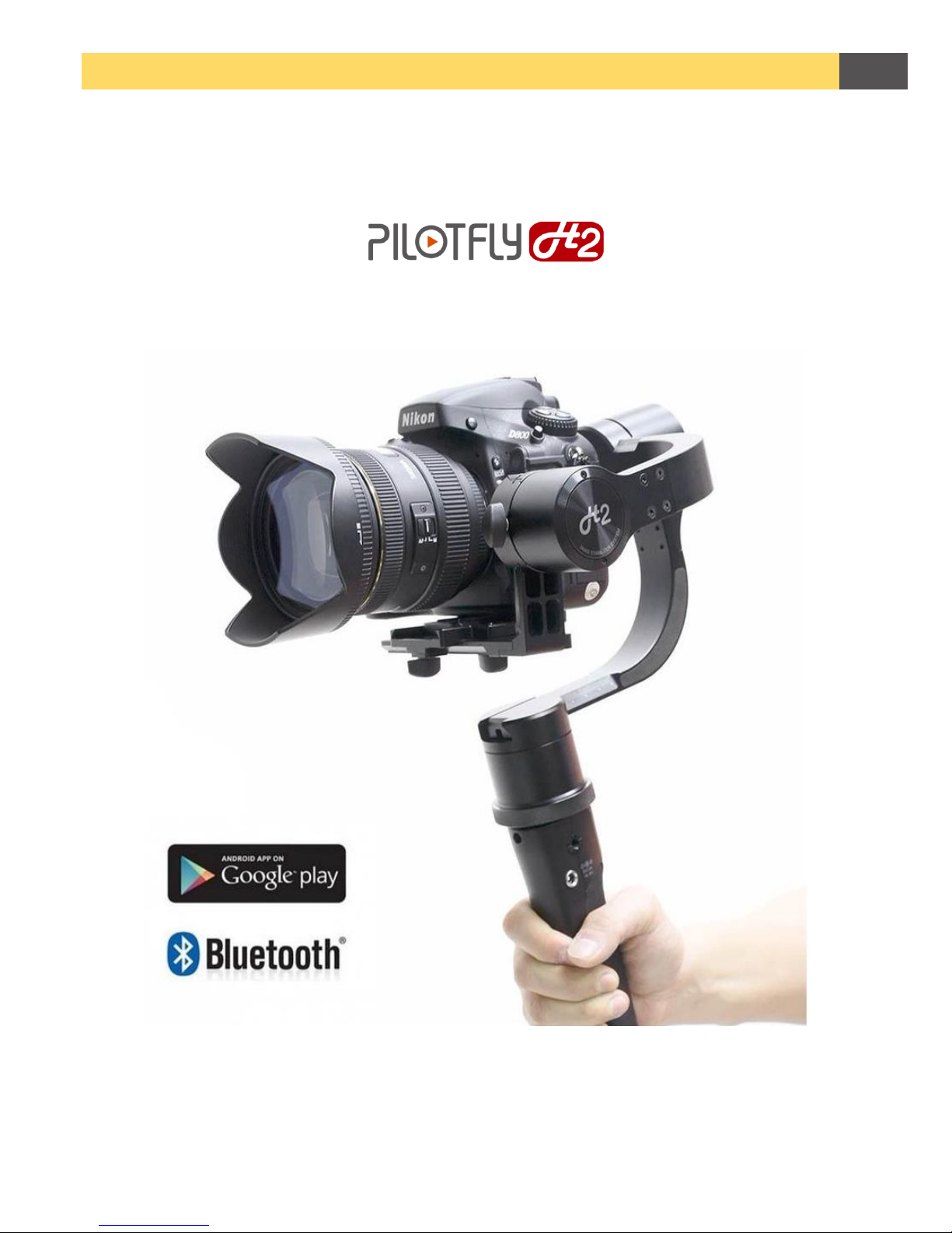
3-axes stabilized steady stative
for mirrorless cameras and digital single lens reflex cameras (SLRs)
Page 2

IM_Rel.1.0.20160516-EN
2
Imprint
Version IM_1.0.CCF.20160516-EN
English, 1st Edition, 05.2016
© Pilotfly
Copyright
This document is protected by copyright. All rights, including those of the whole or partial photo-mechanical
reproduction, duplication and spreading (e. g., by means of data processing, to data carriers and data network
works) as well as content and technical changes, are left in the course of constant product improvements.
Page 3

IM_Rel.1.0.20160516-EN
3
Dear customer,
We thank you for your confidence and wish you a lot of joy and success with your new Pilotfly product. You
have decided in favor of a high-quality product with that. Thanks to new efficient engines with built-in MCUs
(micro controller units) the Pilotfly H2 gimbal is suitable as well for mirrorless cameras as for digital single
lens reflex cameras now, too. Furthermore, it is equipped with 32 bit Alexmos Technology, integrated encoder
and two IMUs (inertial measurement units) and thus it gives newest possibilities for a vibrationless film
production. We have paid the greatest attention to an easy handling as well as a high versatility, flexibility
and endurance. So fast assembling or exchange of your camera is now possible for you and an adjustment
without any additional aids. The battery endurance was increased up to ca. 26 hours.
Even if you are familiar with handling electronic equipments, please read the instruction manual, because it
is an important component of this product. It contains important notes for the safety, the use and the disposal.
Familiarize yourself with all hints to use and safety items before you use the product. Follow the notes and
tips, so that you can use your new product optimally. Only use the product as described and for the indicated
fields of application.
IMPORTANT
AFTER YOU HAVE READ THE INSTRUCTION MANUAL, KEEP IT TOGETHER WITH THE PRODUCT FOR A LATER LOOKING
UP. IN CASE YOU GIVE THE PRODUCT TO ANY THIRD PARTY, HAND OVER IT TOGETHER WITH ALL DOCUMENTS.
Nevertheless, if you should have problems with your product, please address your enquiry to
[email protected] (Taiwan) or [email protected] (Germany). We help you along willingly promptly and give
you information about the next steps.
Service Adresse Taiwan
Pilotfly Technology Co. LTD.
Jiafeng South Rd. No.118, 2F-2
Zhubei City, Hsinchu County 30271
Taiwan
Email: [email protected]
Service Adress Germany
Pilotfly UG (haftungsbeschränkt)
Wendelsteinstr.12
86163 Augsburg
Deutschland
Email: [email protected]
Trademark Proof
© Bluetooth SIG, Inc. Bluetooth SIG, Inc. All rights reserved. Bluetooth ® is a registered trademark of
Bluetooth SIG, Inc. (Special Interest Group), USA.
© 2015 Google Inc. All rights reserved. The Google logo, Google, Android™ and Google Play are registered
brands of Google Inc.
© Microsoft Corporation all rights reserved. Microsoft and Windows are registered trademarks of Microsoft
Corporation in the United States and/or other countries.
© Apple Computer Inc. All rights reserved. Macintosh and OSs are registered trademarks of Apple Computer
Inc. in the United States and/or other countries.
© Linux Torvalds all rights reserved. Linux is a registered trademark of Linus Torvalds.
All other products and brand names which are mentioned in this manual or in the other documentations to
your Pilotfly product are trademarks or registered trademarks of the respective entitled persons.
Page 4
IM_Rel.1.0.20160516-EN
4
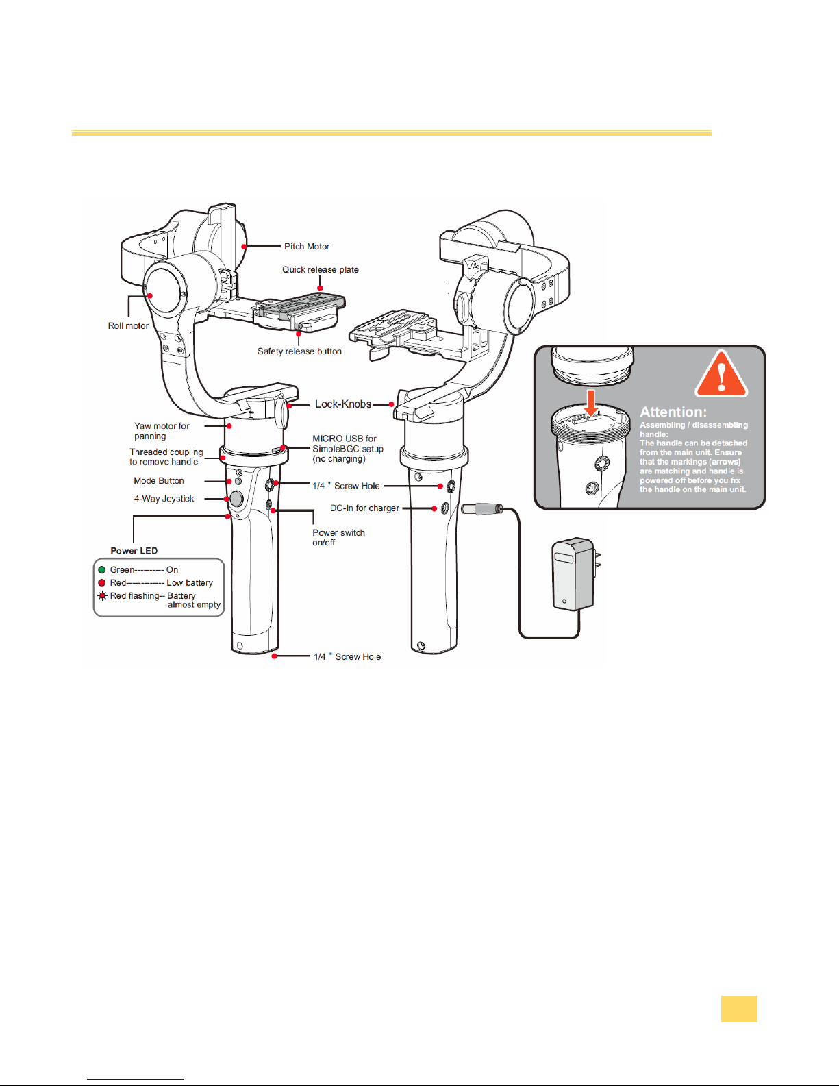
Product Overview
Components
Page 5
IM_Rel.1.0.20160516-EN
5
Product Overview
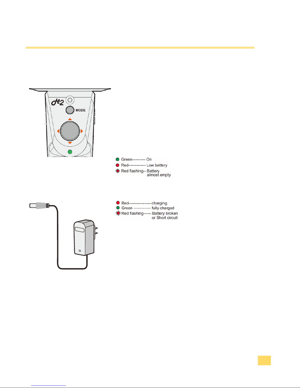
Fuction keys and LED displays
„Mode“ -key button
You can change the mode or calibrate the device by pressing
the key button.
4 way joy-stick
With the joy-stick you can change the angle of inclination of the
camera and the horizontal angle of rotation.
LED display
LED display power adapter
Page 6
IM_Rel.1.0.20160516-EN
6
Product Overview
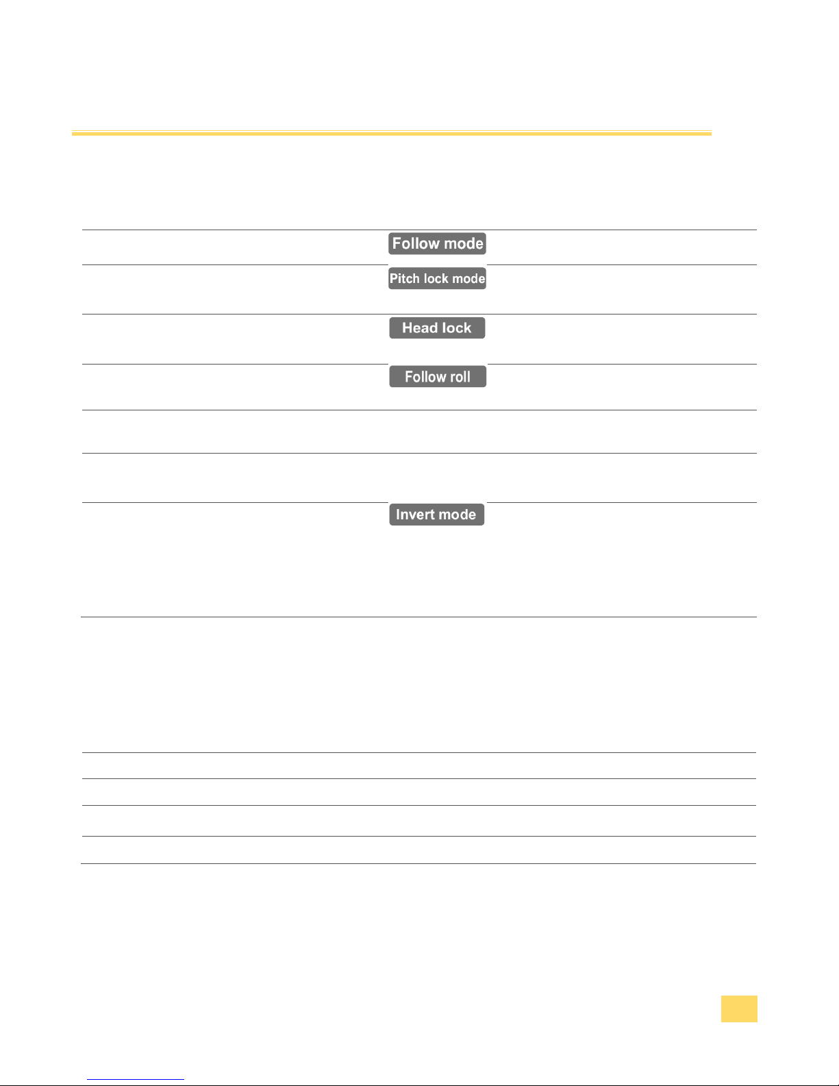
„Mode“ -key button
Key sequence
Function
Description
1 x press
Follow mode
Camera follows the movements.
2 x press
Lock mode of pitch &
roll axis
Camera remains in the horizon and
follows still the horizontal rotation.
3 x press
Lock mode of all 3
axes
All three axes are locked. Camera is
kept in the adjusted position.
4 x press
Follow mode of all 3
axes
All three axes follow the movements.
5 x press
Starting point
„zero position“
Camera returns to "zero position" into
the starting point.
Press and hold 3
seconds
Activates the Gyrocalibration
Avoid any movements and vibrations
during the calibration.
Invert
Turn the grip in the way that it is over
the camera and switch on the device.
The new position is recognized
automatically.
All other above mentioned modes can
also be selcted in the inverted
condition.
Acoustic signals
Action / Event
Sound sequence
Power on
Initialization sound sequence
Initialization in process
Be~Bi~Li~Bi~Li
Calibration in process
Dn~Dn~Dn~Dn~Dn~Dn
Battery nearly empty
Continuous cheeping tone
Page 7
IM_Rel.1.0.20160516-EN
7
Product Overview
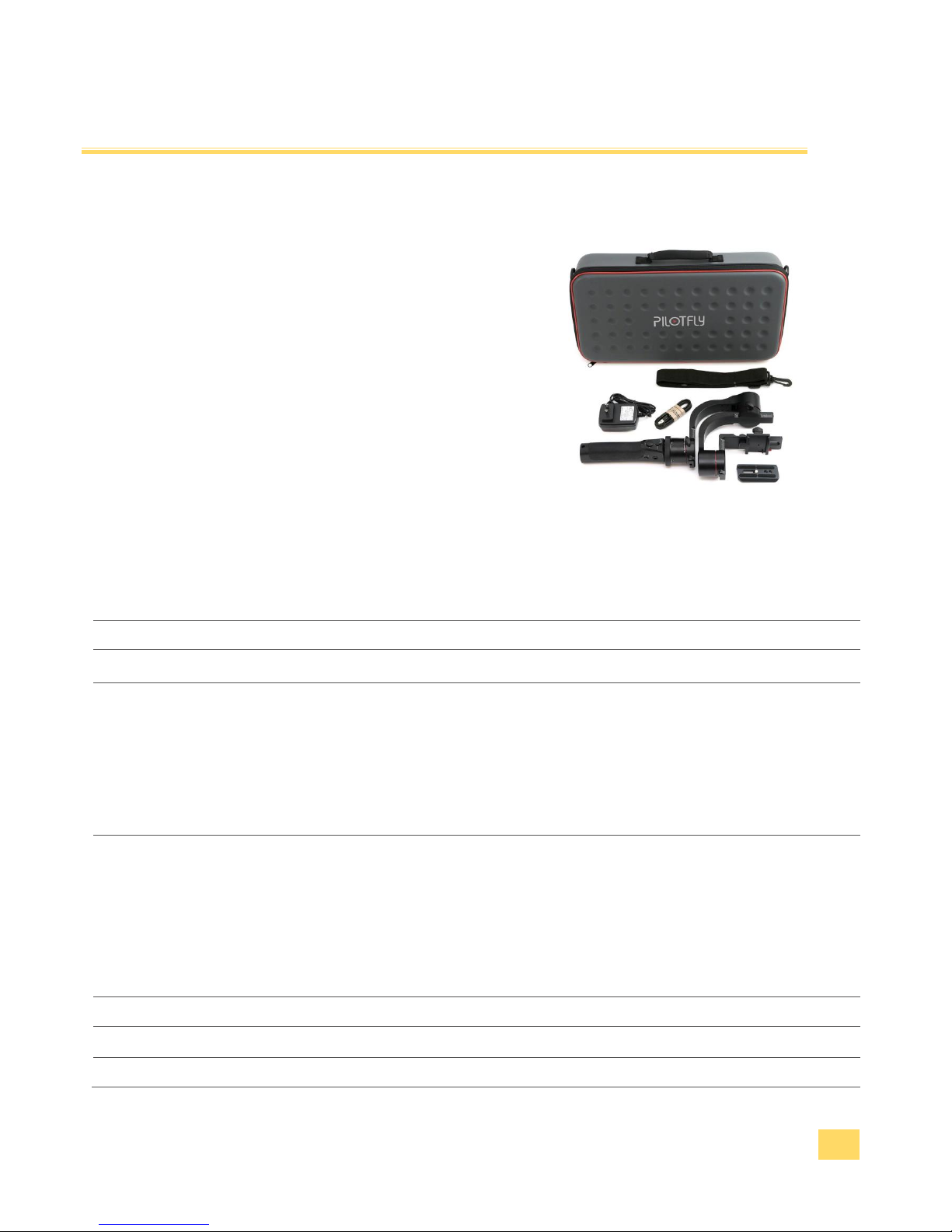
Scope of delivery
1 x Pilotfly H2 gimbal
1 x Carrier bag with belt
1 x USB cable
1 x Power adapter (charger)
1 x Camera assembling plate
1 x Quick start quide
1 x Warranty card
Technical data
Communication interface
Integrated: Bluetooth Version 2.0+EDR / ISM-Waveband
Max. transmitting power 2,5mW/ Range ca. 10m
Operating system
Windows, MAC OSX, LINUX und Android APP
Number of IMU sensors
2
Power supply:
Integrierted battery
4S Li-Po 14.8V / 1800mAh
Battery endurance
Ca. 26 hours – depending on the weight oft he mounted camera
Charger – Power adapter
AC 100 ~ 240V 50Hz/60z; Model: UT-6062C
DC 16,8V / 1000mA
Movement range
YAW
360°
ROLL
Left 100°, Right 240°
PITCH
Top 220°, Bottom 100°
Accuracy
min. ± 0,01° max. ± 0,04°
Unladen weight
ca.1,2kg
Max. additional load (Engine load)
2,2kg
Dimensions
370 x 190 x 190mm
Page 8

IM_Rel.1.0.20160516-EN
8
Table of contents
IMPORTANT SAFETY INSTRUCTIONS .................................................................................................................................. 9
1.1 MEANING OF THE SYMBOLS USED IN THIS INSTRUCTION MANUAL ..................................................................................................... 9
1.2 INTENDED USE ..................................................................................................................................................................... 10
1.3 POSSIBLE DANGERS FOR CERTAIN PERSON GROUPS ...................................................................................................................... 10
1.4 PERSONAL RIGHT AT THE PICTURE OF ONE'S OWN ........................................................................................................................ 10
1.5 THE USE AT CERATIN PLACES AND ENVIRONMENTAL CONDITIONS .................................................................................................... 11
1.6 POWER SUPPLY AND OPERATING CONDITIONS ............................................................................................................................ 12
1.7 PRECAUTIONS AT HANDLING WITH LI-PO ACCUMULATORS ............................................................................................................ 13
1.8 SAFE DISPOSAL ..................................................................................................................................................................... 14
SETUP AND OPERATING ................................................................................................................................................... 15
2.1 UNPACKING ........................................................................................................................................................................ 15
2.2 FIRST STEPS ......................................................................................................................................................................... 16
2.3 ASSEMBLING AND ADJUSTMENT OF THE CAMERA ........................................................................................................................ 18
2.4 SWITCH ON AND BASIC OPERATING .......................................................................................................................................... 20
2.5 FINE ADJUSTMENT WITH HELP OF THE SOFTWARE SIMPLEBGC ...................................................................................................... 21
MAKING A BLUETOOTH CONNECTION ............................................................................................................................. 22
SOFTWARE INSTALLATION ............................................................................................................................................... 23
4.1 INSTALLATION ON WINDOWS .................................................................................................................................................. 23
4.2 INSTALLATION ON LINUX ........................................................................................................................................................ 23
4.3 INSTALLATION ON MAC OS ................................................................................................................................................... 24
4.4 INSTALLATION OF THE ANDROID APP ........................................................................................................................................ 25
USING THE SOFTWARE PC/MAC ....................................................................................................................................... 27
5.2 STANDARD SETTINGS (BASIC) .................................................................................................................................................. 27
5.3 STANDARD SETTINGS (ENCODERS) ........................................................................................................................................... 28
5.4 EXTENDED SETTINGS FOR ADVANCED USERS ............................................................................................................................... 32
5.5 FILTER SETUP ....................................................................................................................................................................... 32
USING THE ANDROID APP ................................................................................................................................................ 35
6.1 GIMBAL SETTINGS ................................................................................................................................................................. 35
6.2 MISC SETTINGS .................................................................................................................................................................... 36
6.3 RC SETTINGS ....................................................................................................................................................................... 37
6.4 FOLLOW MODE .................................................................................................................................................................... 38
6.5 MONITORING ...................................................................................................................................................................... 38
6.6 CONTROL ............................................................................................................................................................................ 39
6.7 SETTINGS ............................................................................................................................................................................ 40
FAILURE / REPAIR ............................................................................................................................................................. 41
MAINTENANCE AND CARE ............................................................................................................................................... 43
PUT OUT OF OPERATION, STORAGE, TRANSPORT ............................................................................................................ 43
SERVICE........................................................................................................................................................................ 44
Page 9
IM_Rel.1.0.20160516-EN
9
Important Safety Instructions
Please read these safety instructions attentively before you take your Pilotfly product into operation to avoid
damages to the product and prevent possible injuries. Keep these safety instructions available for all persons
who will use this product.
1.1 Meaning of the symbols used in this instruction manual
Warning notices are mentioned in the following chapters in the context in which a danger can appear. They
are highlighted especially in the following chapters. The safety instructions within this chapter 1 are generally
important and therefore aren't highlighted separately.
Danger
Endangering with a high risk degree which can mean danger to life
or a heavy injury in the consequence, if it isn't avoided.
Warning
Endangering with a middle risk degree which can mean danger to
life or a heavy injury in the consequence, if it isn't avoided.
Caution
Endangering with a low risk degree which can mean minor or
moderate injury in the consequence, if it isn't avoided.
Caution
Danger of damage to property or environmental damage.
Tip
Highlights tips and information for you.
Page 10

IM_Rel.1.0.20160516-EN
10
Important Safety Instructions
1.2 Intended use
This product is provided exclusively for video recordings in the private use. It isn't provided for commercial or
industrial use. The delivered power adapter is intended exclusively for the use with the Pilotfly H2 gimbal.
Every other use isn't as designated. Prior condition for the use as designated is the attention of the notes of
this instruction manual. Any liability on the part of the manufacturer for damages which result from a use
which is not as designated or caused by unauthorized modifications is excluded. Also use only the
accessories specified by the manufacturer.
Please pay attention to the local regulations and laws of the country in which you use the Pilotfly H2 gimbal.
1.3 Possible dangers for certain person groups
This device is not designated for the use by children and certain other person groups with restricted physical,
sensory or intellectual abilities or lack of experience and/or lack of knowledge. Children and person groups
cannot recognize always possible dangers correctly. Therefore pay attention, that …
children older than 14 years and above mentioned person groups ONLY use the device if they have
been supervised by you or a safety responsible person or if they were introduced respectively, but
NEVER unattended.
children do not play with or clean or open the device unattendedly. You keep away packing foils!
There is danger of suffocation.
you consider possible dangers for children when you lay the cable, e.g. strangling.
1.4 Personal right at the picture of one's own
Pay attention to the restrictions of copyright with regard to filming persons especially at public events, such
as exhibitions, stage productions, celebrations, or similar. Even if the photos are for personal use only. The
consent of the parents has to be sought especially from minors before capturing a photo. Pay attention to the
legal regulations of the country in which you use the device to avoid legal consequences.
Page 11

IM_Rel.1.0.20160516-EN
11
Important Safety Instructions
1.5 The use at ceratin places and environmental conditions
For a safe use of your Pilotfly H2 you have to pay attention, that …
you use the device only at places which are suitable also for your camera. Implicitely follow the
instructions within the instruction manual of the camera which you use with the gimbal.
you follow the instructions of restrictions or embargoes for accumulator operated equipment at
explosive places. Tank areas and areas where the air is containing chemicals or fine particles, e. g.
grain, powdered metal. Explosive areas aren't always identified explicitly.
you could be distracted when using the device in the current road traffic. This can lead to an accident
and you endanger the health of others and yours and you have to expect legal consequences.
Therefore use the device at a stationary vehicle. Always notice the legal regulations of the country
where you use the device.
you operate the device only within the permitted environmental temperature range. Details see at
Technical data.
you do not expose the device to any strong temperature fluctuations. Atmospheric humidity can
condense and lead to electrical short circuits.
you do not expose the device to any direct heat sources, such as heaters, or direct solar radiation.
Otherwise it can overheat and be damaged irreparably.
you avoide the contact with aggressive liquids.
you avoide the contact with splashing and dripping water.
you never dive it under water or other liquids.
Page 12

IM_Rel.1.0.20160516-EN
12
Important Safety Instructions
1.6 Power supply and operating conditions
For a safe use of your Pilotfly H2 pay attention, that …
you make sure that the specified voltage data on the rating label are fitting to the specification of the
power socket.
you never grasp the power adapter with wet hands. If you want to pull the power adapter out of the
power socket, you always pull directly at the power adapter. Never pull at the cable, it could be
damaged. Furthermore, never transport the device at the cable.
the cable is not modified, jammed, folded, charged by heavy objects, crossed over by vehicle, comes
into touch with heat sources or sharp edges. In addition, it mustn't become a stumbling trap.
you regularly check the device, the accessories and the cables for damages. If you should notice
damages, you may not continue to use the device any more. For repairs send it only to the Pilotfly-
Service.
you immediately switch off the device, if you notice smoke, unusual noises or smells. Do not continue
using it any more before a check was performed by an expert. Send it only to the Pilotfly-Service.
you switch the device off and you unplug the power adapter from the power socket before you clean
or service it.
you always pull the power adapter out of the power socket at a thunderstorm. At a thunderstorm the
equipment which is attached at the power grid can be damaged.
you do not touch the device during a thunderstorm. Touching metal parts during a thunderstorm can
cause an electric shock.
you use the power adapter only indoors and dry surroundings.
you do not cover the power adapter to avoid a damage by not allowed temperature rise.
the power socket is near by the connected device, so that you easily have access to separate the
device from the power grid in case of failure.
Page 13

IM_Rel.1.0.20160516-EN
13
Important Safety Instructions
1.7 Precautions at handling with Li-Po accumulators
Li-Po accumulators require special handling. Improper handling can shorten the life time or lead to fire or
explosions, bleeding or overheating. Pay attention, that …
you only use the power adapter which is contained in the scope of delivery for charging the
accumulator of the Pilotfly H2. Generally, for charging Li-Po accumulators only use battery chargers
with a Li-Po charging program and balancer. Charge the accumulator only supervised on a fire-proof
pad.
you replace the accumulator only by an identical or equivalent type.
you pull the power adapter out of the power socket after finished the charging process.
you do not throw an accumulator into open fire nor submit heat to it.
you do not open, do not disassemble and do not deforme accumulators.
you do not drop or push accumulators.
you do not transport or store accumulators together with objects made of metal, such as paper clips
or hairpins. There is a short circuit if the poles of an accumulator come into touch with metal objects.
Therefore, use fire protection bags for the storage e.g. protective covers like Lipo-Bags, Lipo-Safety
Bags. These are fire-resistant and protect against open fire. In the case of a fire use CO2, powder or
foam extinguishers. Do not use water. For storage and for the transportation use the same means.
you do not charge accumulators next to inflammable media.
during longer non-utilization you store the device within the delivered carrier bag at a cool and dry
place. Best at environmental temperatures from +15°C to +25°C. Avoid places with extreme
temperatures.
you absolutely keep the accumulators away from children. The cells look like "chewing gum" or
"chocolate" in the packing and can be swallowed. In case a cell has been swallowed immediately call
a doctor to help. Due to the poisonous substances within the accumulators, there is serious danger!
Keep the accumulators in a way that unauthorized persons have no access, especially not children
and animals.
accumulators getting hot when charging. Never touch hot accumulators! Otherwise there is the danger
of burnings!
you do not exchange accumulators in potentially explosive surroundings. Spark blow arising from it
can cause an explosion!
Page 14
IM_Rel.1.0.20160516-EN
14
Important Safety Instructions
1.8 Safe disposal
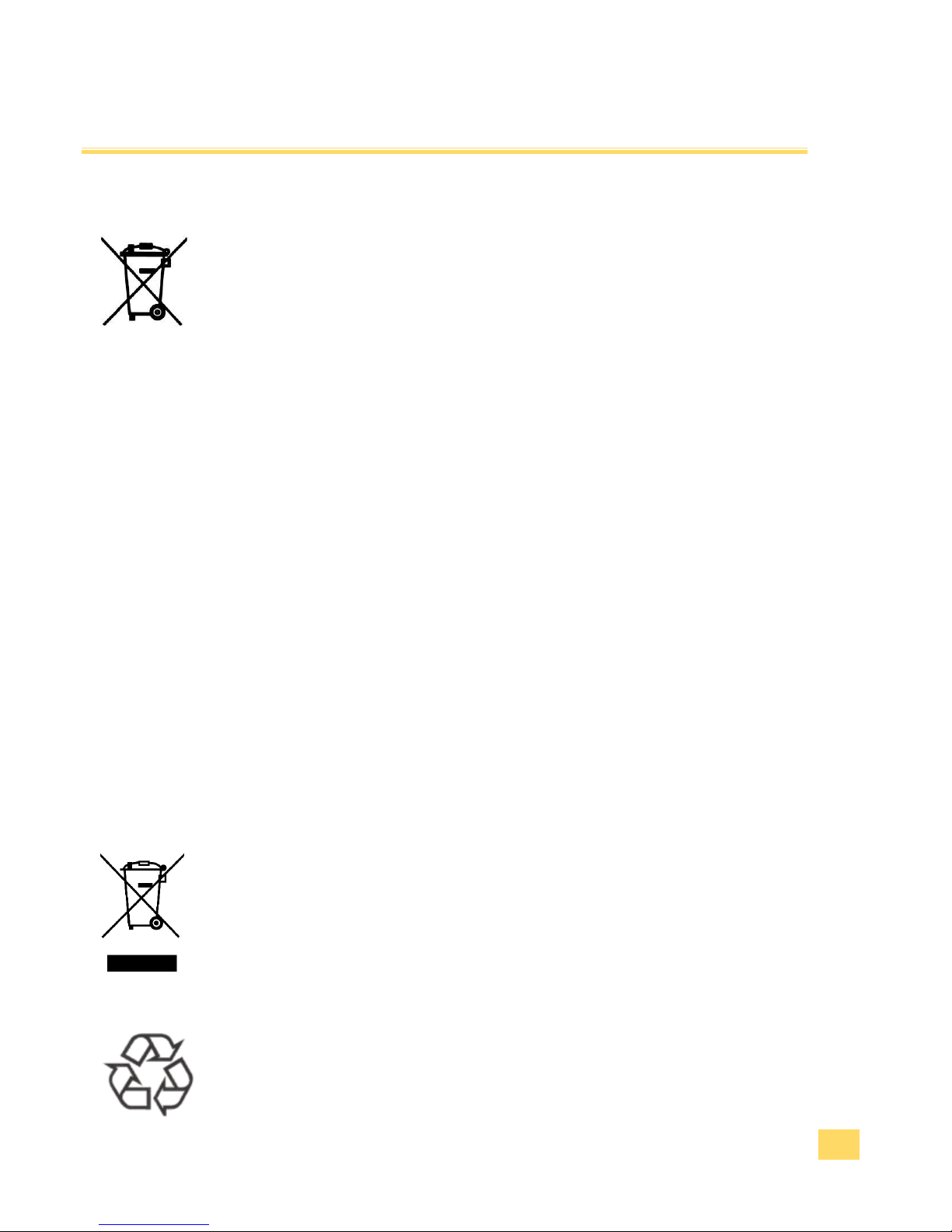
Endangering health and environment by accumulators and batteries!
In the Europian Economic Area this symbol indicates that consumers are required by
law to return all waste batteries to either a store or another collection point for waste
batteries. Waste batteries should never be placed in the household garbage, or
anywhere in the environment. This is indicated by the symbol comprising a crossedout wheeled bin that appears on batteries and/or battery packaging. In the interest of
facilitating waste battery collection, manufacturers of portable batteries have
established a joint collection.
Retailers are required by law to take back waste batteries free of charge. In Germany,
collection boxes in which consumers can deposit waste portable batteries are
available at all stores that sell portable batteries, e.g. supermarket, discounter,
drugstore or construction market. Some municipalities take waste batteries back, e.g.
via vehicles that make regular collections of hazardous waste, or recycling centres.
The legal limit for mercury within button cells is 2 percent (20 grams per kilogram) of
mercury, while the limit for all other types of batteries is 0.005 percent (5 milligrams
per kilogram). Portable-battery cadmium content is limited to 0.002 percent (20
milligrams per kilogram). Batteries used for cordless power tools, emergency or alarm
systems emergency lighting, and medical devices are exempt from this limit.
For batteries whose mercury, cadmium or lead content exceeds specific limit values,
this fact must be indicated on the battery or packaging, below the symbol of the
crossed-out whelled bin.
Please take care e. g. by taping the individual connection poles that the batteries to
be disposed of are unloaded and the connection poles are protected from short
circuits.
Potential negative consequences to the environment and human health!
In the Europian Economic Area this symbol indicates that this product shall not be
treated as houshold waste. Instead it has to be taken to an applicable collection point
for the recycling of electrical and electronic equipment. By ensuring this product is
dispoesed of correctly, you will help prevent potential negative consequences to the
environment and human health, which could otherwise be caused by inappropriate
waste handling of this product.
In the Europian Economic Area this symbol indicates that you should dispose the
packing materials environmentally sensible according to the local regulations.
Page 15

IM_Rel.1.0.20160516-EN
15
Setup and operating
2.1 Unpacking
Danger
Serious danger! Keep packing foils away from children. There is danger
of suffocation.
Danger
Serious danger! Absolutely keep accumulators from children away. If a
child swallowed a cell immediately call a doctor to help. Keep the
accumulators in a way that no unauthorized persons have access,
especially children and animals.
Caution
Environmental damage! In principle send the device in the original
packing so that it doesn't take damage. Therefore, keep the packing.
Packing materials which is no more required dispose of environmentally
sensible according to the local regulations.
1. Open the transport box very carefully to prevent a possible damage to the product. This can happen
if a knife is used for opening with a long blade.
2. Your Pilotfly product is in its own carrier bag. Unpack it and all its accessories.
3. Please check the completeness and integrity of the scope of delivery.
4. Contact us immediately Pilotfly-Service, if parts should be missing or are defect.
Page 16
IM_Rel.1.0.20160516-EN
16
Setup and operating
2.2 First steps
Warning
Injury danger! Check the device and the cable before every use. A
damaged device may not be used.
Warning
Injury danger! Do not take the device in operation in explosive
surroundings! Follow the safety instructions to this 1.5 The use at
ceratin places and environmental conditions.
Caution
Property damage! Make sure that the device is switched off at the grip
before you put this together with the gimbal. Otherwise the device can
be damaged by short circuit.
Tip
Function! Before the first use, charge the accumulator that the device
works optimally.
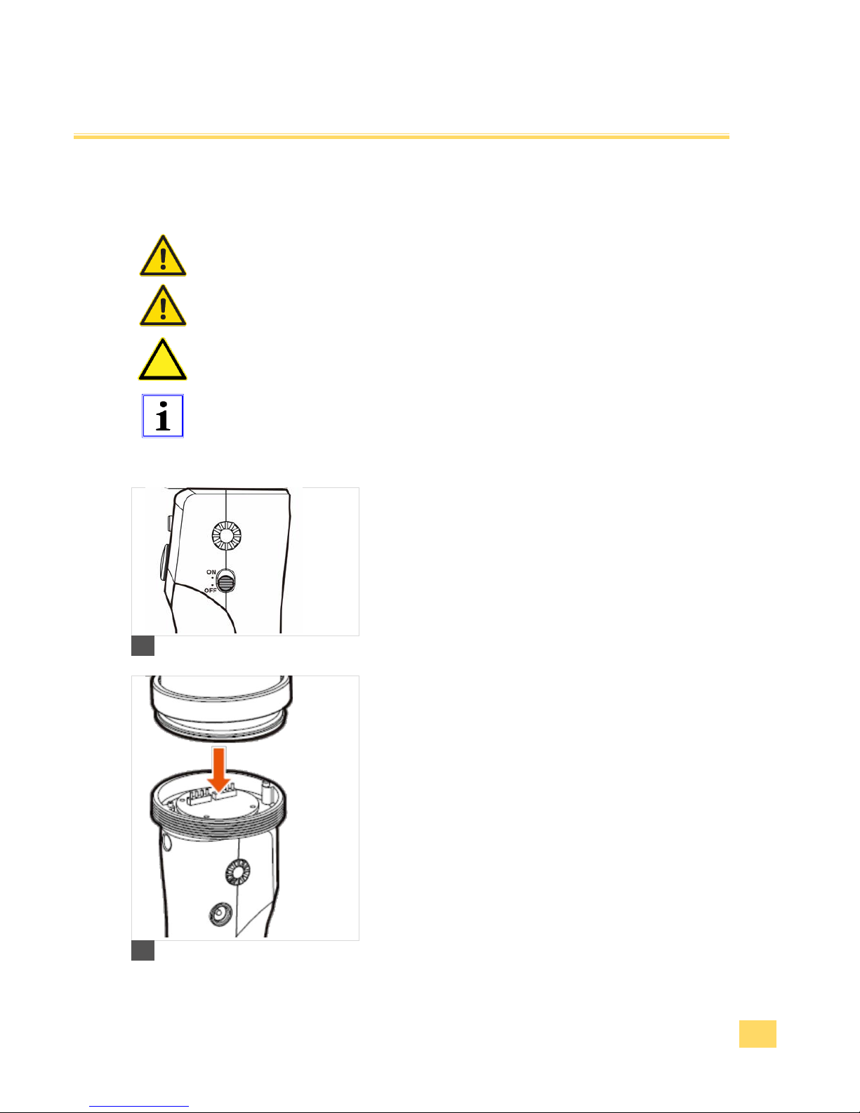
1. Check, that the device is switched off.
1
2. The grip is screwed together with the gimbal.
2
Page 17
IM_Rel.1.0.20160516-EN
17
Setup and operating
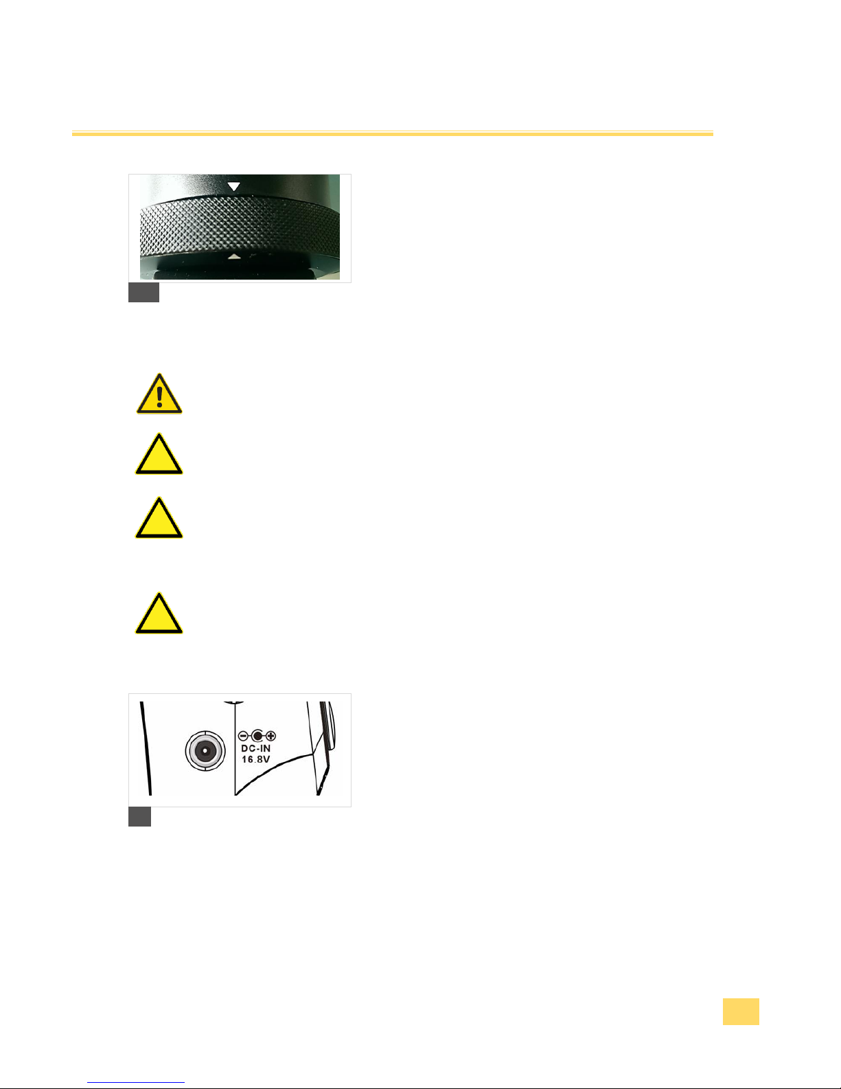
3. Check at the assembly that the grip fits with the markings
(arrows) and is screwed together tightly.
3
Warning
Injury danger! Never grasp the power adapter with wet hands.
Caution
Property damage! Use only the delivered power adapter for charging.
Caution
Property damage! Before plugging the power adapter in to the power
socket, make sure that the electrical data indicated on the rating label
agree with the specification of your power socket. Follow the safety
instructions 1.6 Power supply and operating conditions.
Caution
Property damage! Always unplug the power adapter only directly. Never
pull at the cable, it could be damaged.
4. Put the power adapter into the fitting power socket.
Connect the connecting plug with the charge jack.
5. The LED shines red.
6. The LED shines green when the charging process is
completed. After the completed charging process pull the
power adapter out of the power socket again.
4
Page 18
IM_Rel.1.0.20160516-EN
18
Set up and operating
2.3 Assembling and adjustment of the camera
Warning
Injury danger! Implicitely follow the safety instructions and warning
notices within the instruction manual of your camera!
Tip
Function! Make sure that both, the camera and the gimbal remain
switched off during the assembly and adjustment.
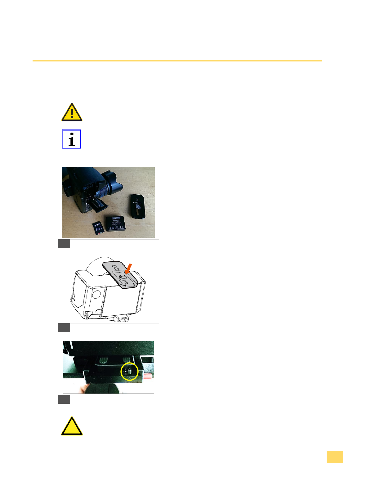
1. Remove the objective lid and make sure that the battery
and memory card is installed in the camera before you
attach the camera to the gimbal.
5
2. Attach the adapter plate to the camera.
3. Make sure that the camera is fixed tightly and upright.
6
4. Slide the camera with the adapter plate into the quickaction locking system.
7
Caution
Property damage! Make sure that the locking bolt is within the adapter
plate, so that the camera cannot fall out.
Page 19
IM_Rel.1.0.20160516-EN
19
Setup and operating
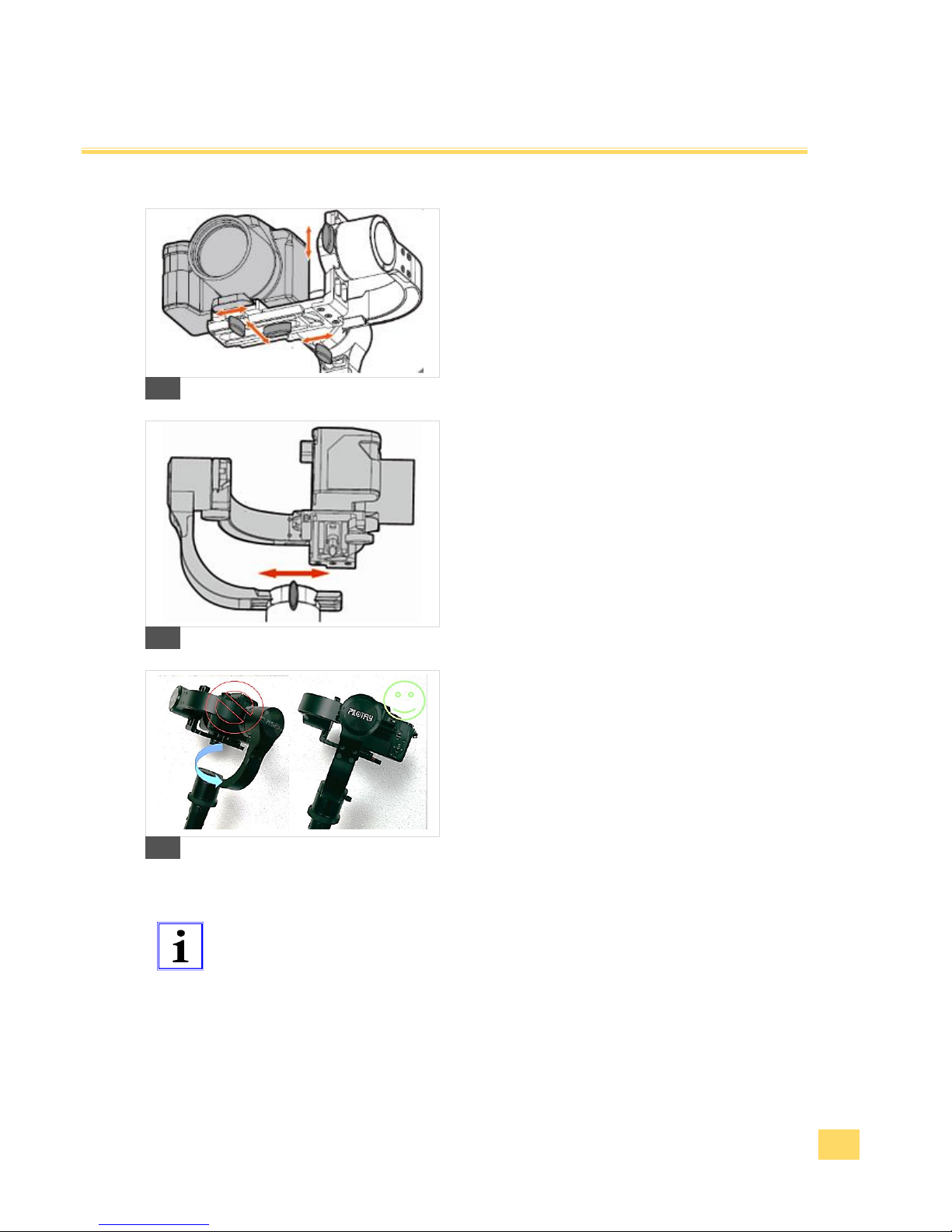
5. Roll & Pitch. Loosen the lock screws and balance
the camera forwards and backwards as well as on
the right and on the left roughly. A good balance is
achieved if the camera keeps the position
independent.
8
6. Yaw. Incline the device by approx. 45° to the left or
to the right. The yaw axis position mustn't change
now. If the axis turns, you must proceed balancing
the axis.
7. Loosen the lock screw of the yaw axis and move
the L-arm forwards or backwards until the yaw axis
independently holds its position.
9
10
Tip
Function! After all, check the tight fixation of all screws well so that the
adjusted balance remains unchanged.
Page 20
IM_Rel.1.0.20160516-EN
20
Setup and operating
2.4 Switch on and basic operating
Warning
Injury danger! Before you switch on the device, please read the
instruction manual completely and get familiar with all use and safety
instructions. Follow the notes and tips so that you can use the device
optimally.
Tip
Function! Druring processing a programmed script, the joy-stick is
locked.
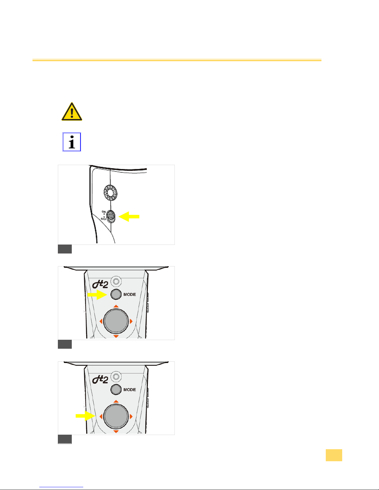
1. Power On / Off. Hold the device with an assembled
camera upright and slide the switch into the "ON"
position. The device will be initialized and you hear
a sound sequence. The LED display shines green.
2. After switching on, the device is in the follow mode.
The device is ready to use.
11
3. Using. Set the desired operating mode or function
with the "Mode"-key button Product
overview“Mode“-key button.
12
4. Control. You can change the angle of inclination of
the camera or the horizontal angle of rotation
manually over the joy-stick.
13
Page 21

IM_Rel.1.0.20160516-EN
21
Setup and operating
2.5 Fine adjustment with help of the Software SimpleBGC
Tip
Function! Achieve the best possible stabilization effect by using the
SimpleBGC software 5.Software GUI. Since every camera has a
different weight, the settings of the PID controller and the engine power
can be adjusted and optimized individually. You achieve the best result
to stabilization only by optimized fine adjustments. Perform a Gyro
calibration at the beginningProduct overview“Mode“-key button.
1. PID control settings for all 3 axes 5.Software GUI
P – The „P“ value describes the power of disturbance response. Higher values means a stronger response
reaction to external disturbance. Raise this value until the stabilization quality of fast disturbances will be
adequate. If the “P” value is too high, oscillations of the axis will start to be present. These oscillations will
get worse if there are vibrations that reach the IMU sensor board. If oscillations occur, raise the “D” parameter
by 1 or 2 units, and then try to raise the “P" value again.
D – The “D” value reduces the reaction speed. This value helps to remove low-frequency oscillations. A “D”
value that is too high can cause high-frequency oscillations, particularly when the IMU sensor is exposed to
vibrations.
I – The “I” value changes the moving speed at which the gimbal moves to incoming joystick or RC
commands and to move the gimbal back to neutral. Low values result in a slow and smooth reaction to
joystick or RC commands and to getting back to neutral. Increase this value to speed up the movement.
Consider that faster movements make the system more prone for disturbances.
2. Adapting the engine performance to the camera weight 5.Software GUI
You must adapt the necessary voltage supply of the respective engine to the weight of your camera here.
The adjustment range for the voltage values is 0-255, where 255 corresponds to the maximum accumulator
voltage. If too low values are adjusted, the respective engine doesn't have sufficient strength to move and to
stabilize sufficiently the corresponding axis together with your camera. Adjust the lowest value which just
guarantees a sufficient hold moment and a good stabilization.
Caution
Property damage! Too high adjusted voltage values for the engine
power cause a strong warming of the engine. High temperatures above
80°C lead to an engine damage. Perform the adjustments very
cautiously and prudently!
Page 22
IM_Rel.1.0.20160516-EN
22
Making a Bluetooth connection
Tip
Legal hint! All Pilotfly products are equipped with an active Bluetooth to
be able to make a wireless connection with the device and control this
via remote control. Probably there are restrictions at certain places for
the use of a Bluetooth-capable and wireless equipment. Please, if you
aren't sure whether you may use a wireless device in certain
surroundings (e. g. airplane or hospital), ask the responsible persons
before you switch on the device and activate Bluetooth with that.
Tip
Function! Bluetooth and Wireless LAN equipment work in the same
frequency domain and can disturb themselves under each other.
Tip
Function! Note that not coupled equipment only can be found if their
visibility is switched on.
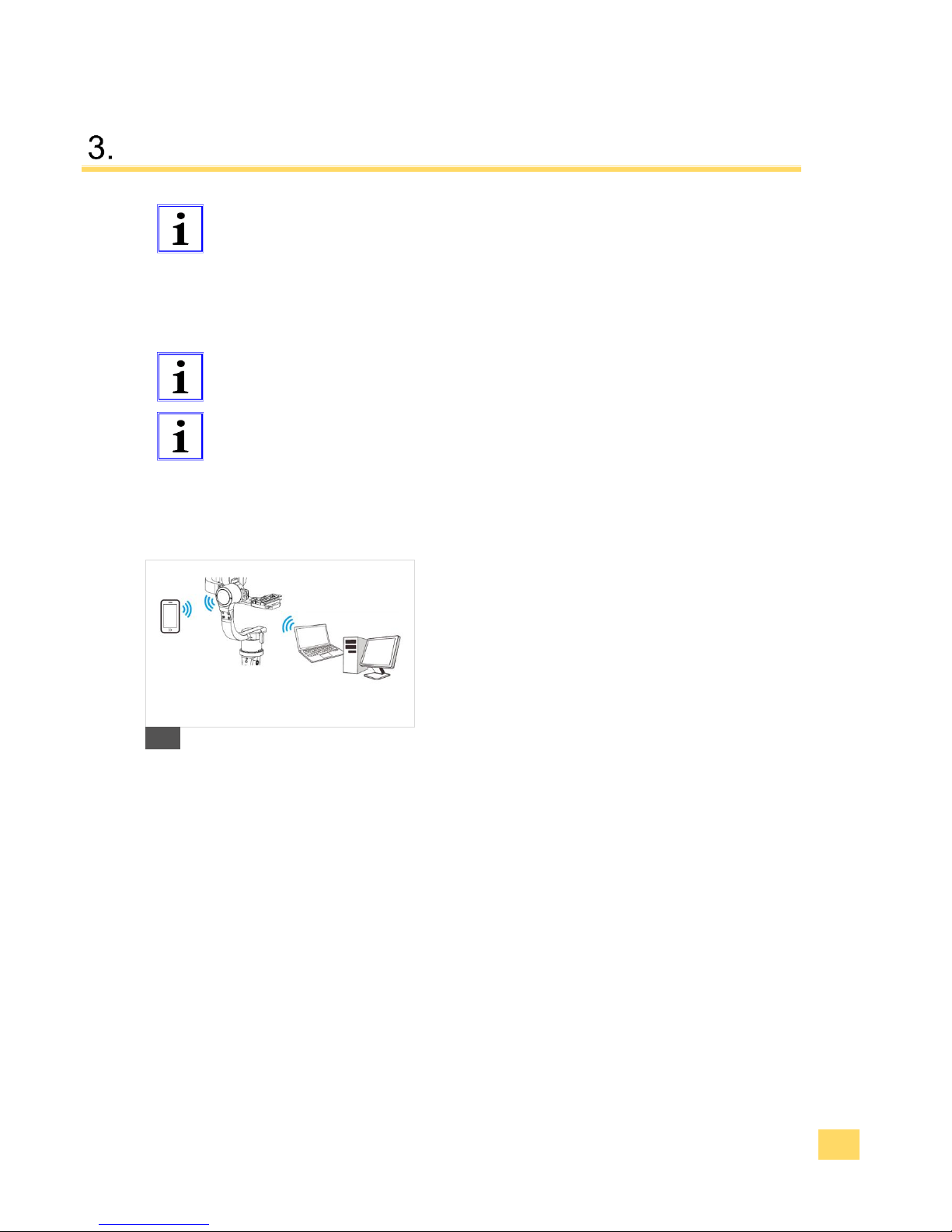
1. Open the Bluetooth settings at your PC, MAC or
android smartphone, and look for a new bluetooth
device while your Pilotfly device is switched on.
2. Follow the instructions on the display.
3. Make a connection (Pairing). Please, on request of a
password enter the following password 1234.
14
Page 23

IM_Rel.1.0.20160516-EN
23
Software Installation
All Pilotfly products use the Alexmos Chip and therefore can be used with the SimpleBGC software which
is provided by Basecam Electronics. The software can be installed on different operating systems, such as
Windows, OSs, Linux and Android App.
4.1 Installation on Windows
1. Go to our webseite www.pilotfly.de or www.pilotfly.com.tw on to the support page.
2. Download the most current version of the SimpleBGC software there.
3. Download the most current version of the "CP2102 USBtoUART" driver there.
4. Install the driver CP2102 USBtoUART.
5. Extract the SimpleBGC Software and start the Software with SimpleBGC_GUI.exe
4.2 Installation on Linux
1. Go to our webseite www.pilotfly.de or www.pilotfly.com.tw on to the support page.
2. Download the most current version of the SimpleBGC software there.
3. Extract the SimpleBGC Software and start the Software with run.sh
Page 24
IM_Rel.1.0.20160516-EN
24
Software Installation
4.3 Installation on MAC OS
1. Go to our webseite www.pilotfly.de or www.pilotfly.com.tw on to the support page.
2. Download the most current version of the SimpleBGC software there.
3. Download the most current version of the "CP2102 USBtoUART" driver there.
4. Ensure, that you have installed Java Run Time.
5. Install the driver CP2102 USBtoUART.
Tip
Function! The software SimpleBGC of Basecam Electronics uses a
virtual COM interface. Thus you must create lock file before, that the
software works under OSs. Proceed very attentively as follows for it
especially if you are less experienced:
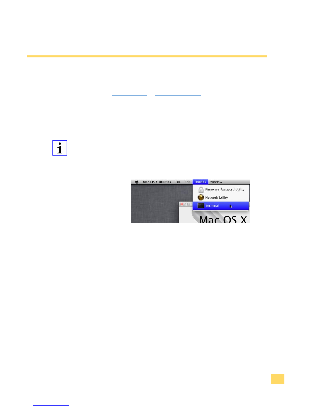
Start the terminal under „Utilities“:
Create a folder „/var/lock“ with the following command:
sudo mkdir /var/lock
Password-Request by MAC OS. Enter your Log-In password and
confirm by pressing Enter.
Change the release of the prepared folder with the following
order: sudo chmod 777 /var/lock
Either allow your system to run non-signed applications by setting
this in System Preferences > Security & Privacy > General >
Allow Applications downloaded from: Anywhere
Or you can allow just this one app to run by answering Open
when prompted by the system dialog.
6. Extract the SimpleBGC Software and start the Software with SimpleBGC_GUI.jar
Page 25
IM_Rel.1.0.20160516-EN
25
Software Installation
4.4 Installation of the Android App
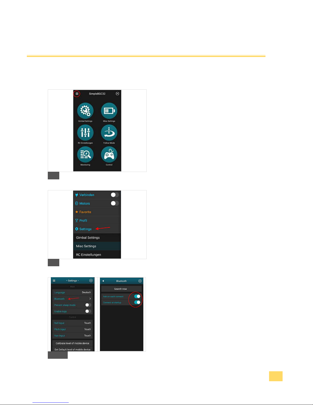
1. Go to the Google Play Store and download the
SimpleBGC App there.
2. Ensure that Pilotfly product is paired with your
Android Smartphone or Tablet 3. Making a
bluetooth connection.
3. Start the SimpleBGC32 Android App and connect
to the paired device by extract the menu left
corner.
A
4. Then press on „Settings“.
B
5. Then press on „Bluetooth“ and search for new
devices. Enable „Ask on each connect“ and
„Connect at startup“.
C
Page 26
IM_Rel.1.0.20160516-EN
26
Software Installation
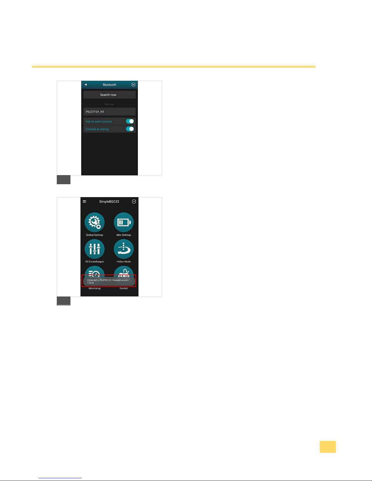
6. The Bluetooth window should show you detected
devices as shown.
D
7. Close the application and start it again while the Pilotfly
device is powered on.
8. While starting the application the App tries to connect
with the Pilotfly device and will show a Pop-up window
with information of proper connetion and current
firmware version.
9. Now the application is ready to use with your Pilotfly
device.
E
Page 27
IM_Rel.1.0.20160516-EN
27
Using the Software PC/MAC
Tip
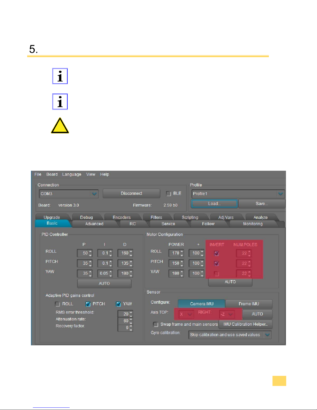
Function! Connect the device via USB cable or Bluetooth 3. Making
a bluetooth connection with a PC or MAC to optimize the stabilization
settings or to upgrade the firmware.
Tip
Function! Implicitly make a backup copy of your profiles before you
make changes or upgrade the firmware.
Caution
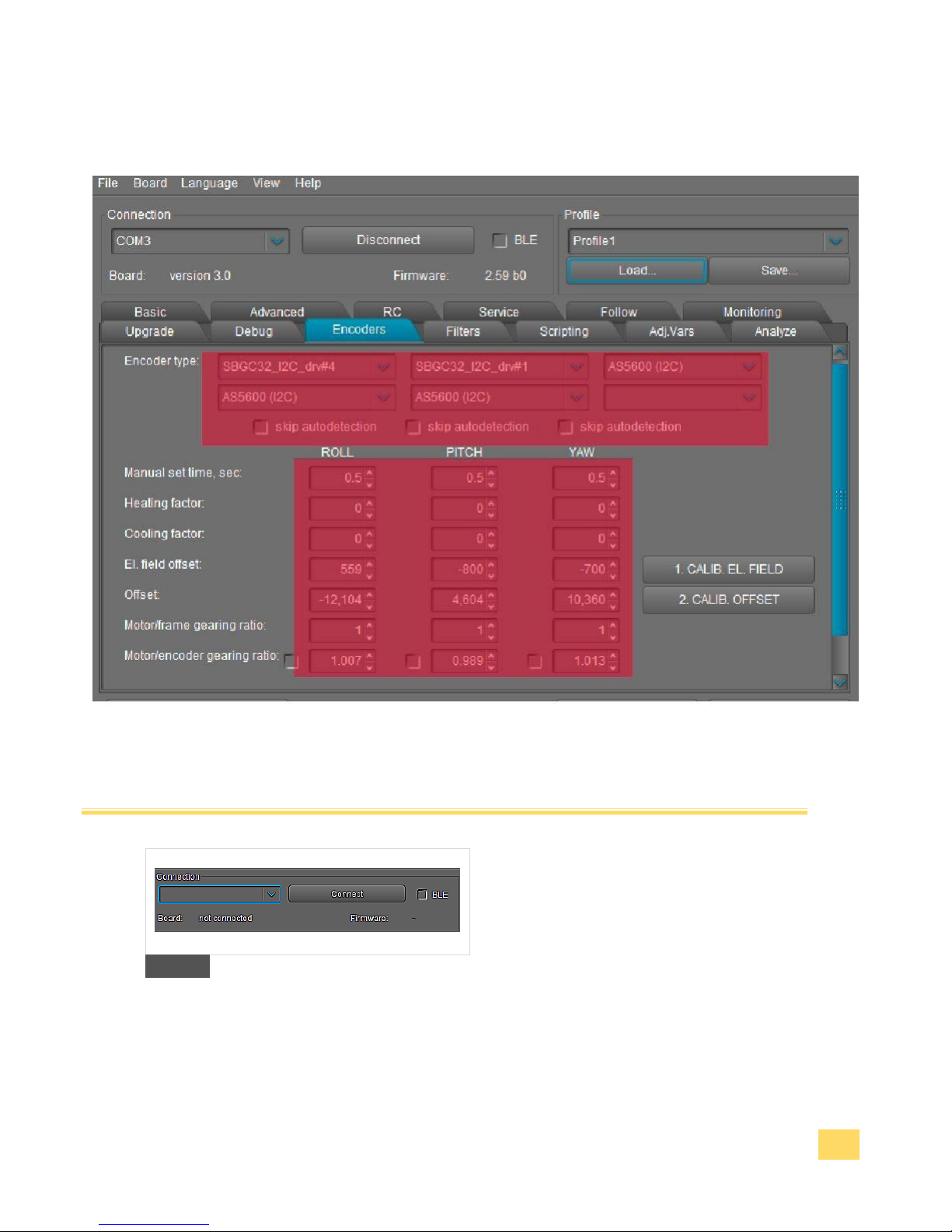
Property damage! Don't make any changes in the red highlighted areas!
The software offers many possibilities. For the optimal use of your Pilotfly
H2 you only have to use the brightly highlighted outlined functional
blocks.
5.2 Standard settings (Basic)
Page 28
IM_Rel.1.0.20160516-EN
28
5.3 Standard settings (Encoders)
Using the Software PC/MAC
1. USB-cable-connection.
Connect the device with a Micro-USB
cable. Choose the COM interface in the
drop down menu and press the button
"Connect".
15
Page 29
IM_Rel.1.0.20160516-EN
29
2. Bluetooth-connection. (Optional)
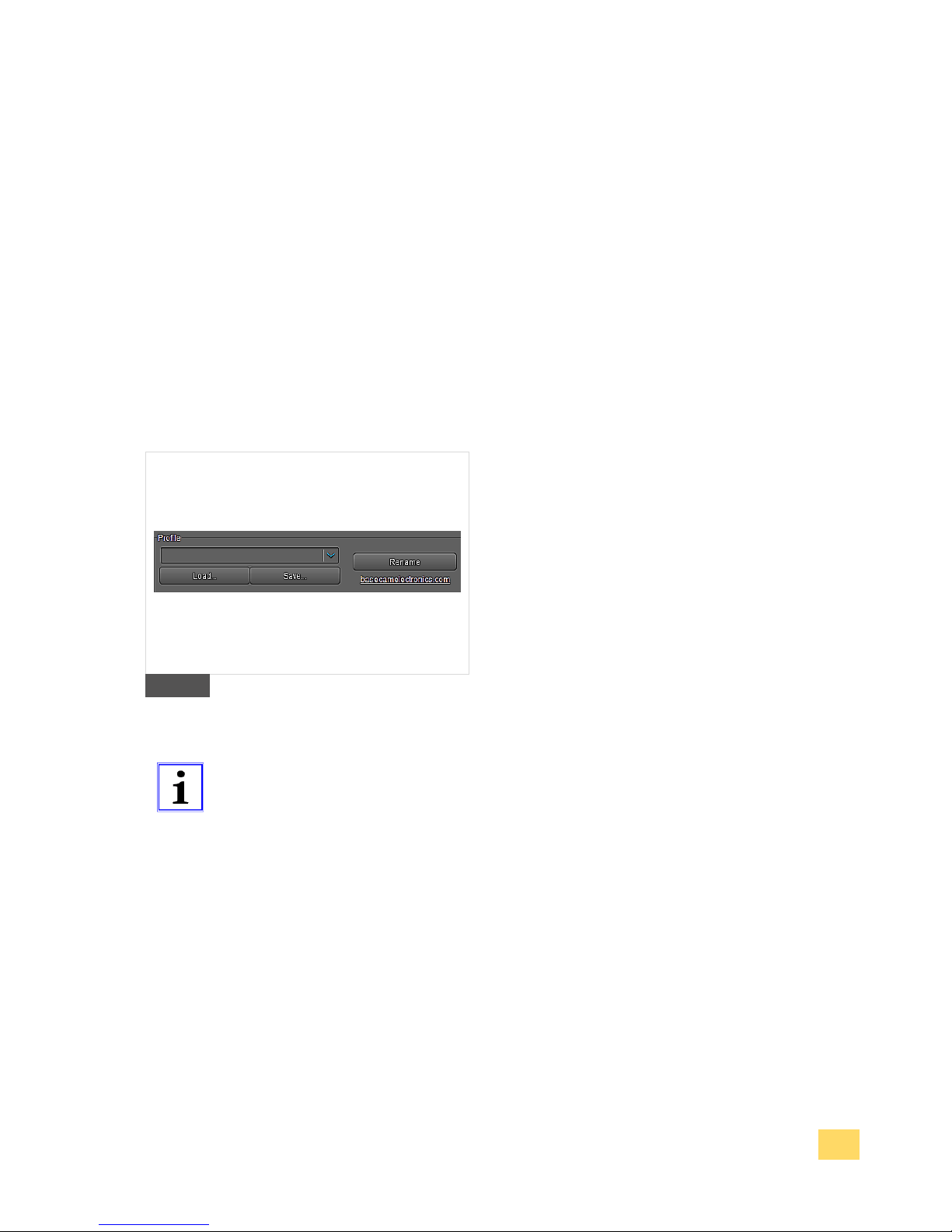
Alternatively connect the device via
Bluetooth. Mark the check box "BLE",
choose the COM interface in the drop down
menu and press the button "Connect".
The connection status is shown on the
lower border of the functional block. At a
successful connection all preinstalled
profiles are downloaded from the device.
The settings of the current profile are
displayed.
3. Save a profile onto the computer.
Store the current profile by pressing the
button "Save". You can rename the profile
by pressing the "Rename"- button.
4. Open profile from computer. Press the
button "Load" to open and load the settings
of a stored profile. The settings of the
loaded profile are displayed.
16
Tip
Function! Over the „File“ menu you are able to load and save all profile
files at the same time by pressing „Load profile(s) from a file…“ and
„Save all profiles to a file…“.
Page 30
IM_Rel.1.0.20160516-EN
30
Using the Software PC/MAC
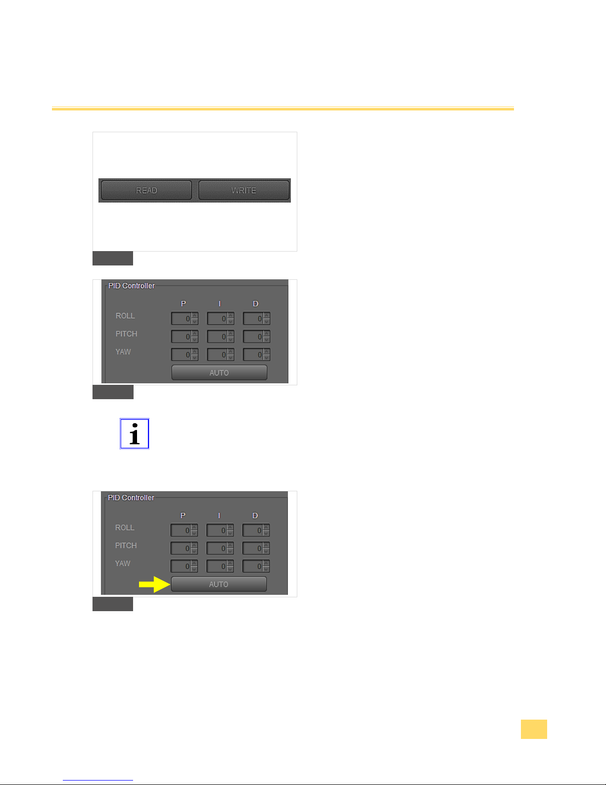
5. Upload a profile to the device.
Upload the current profile to your device by
pressing the button "WRITE". Only the
current displayed profile will be transfered!
6. Download a profile from the device.
Download all profiles from the device by
pressing the button "READ". The current
profile is displayed.
17
7. Manually optimizing of the PID controller
settings.
Implicitly notice 2.5 Fine adjustment with
help of the Software SimpleBGC.
8. Adjust the PID parameters in this functional
block.
18
Tip
Function! During the adjustment you must hold the device
vertically and stably in your hand. If necessary support the device
with a firm pad (table surface, tripod etc.). Perform a Gyro
calibration at the beginning Product Overview“Mode“-key
button.
9. Automatically optimizing of the PID
controller settings.
Implicitly notice 2.5 Fine adjustment with
help of the Software SimpleBGC.
10. Press the button "AUTO" in the functional
block PID controller.
19
Page 31
IM_Rel.1.0.20160516-EN
31
Using the Software PC/MAC
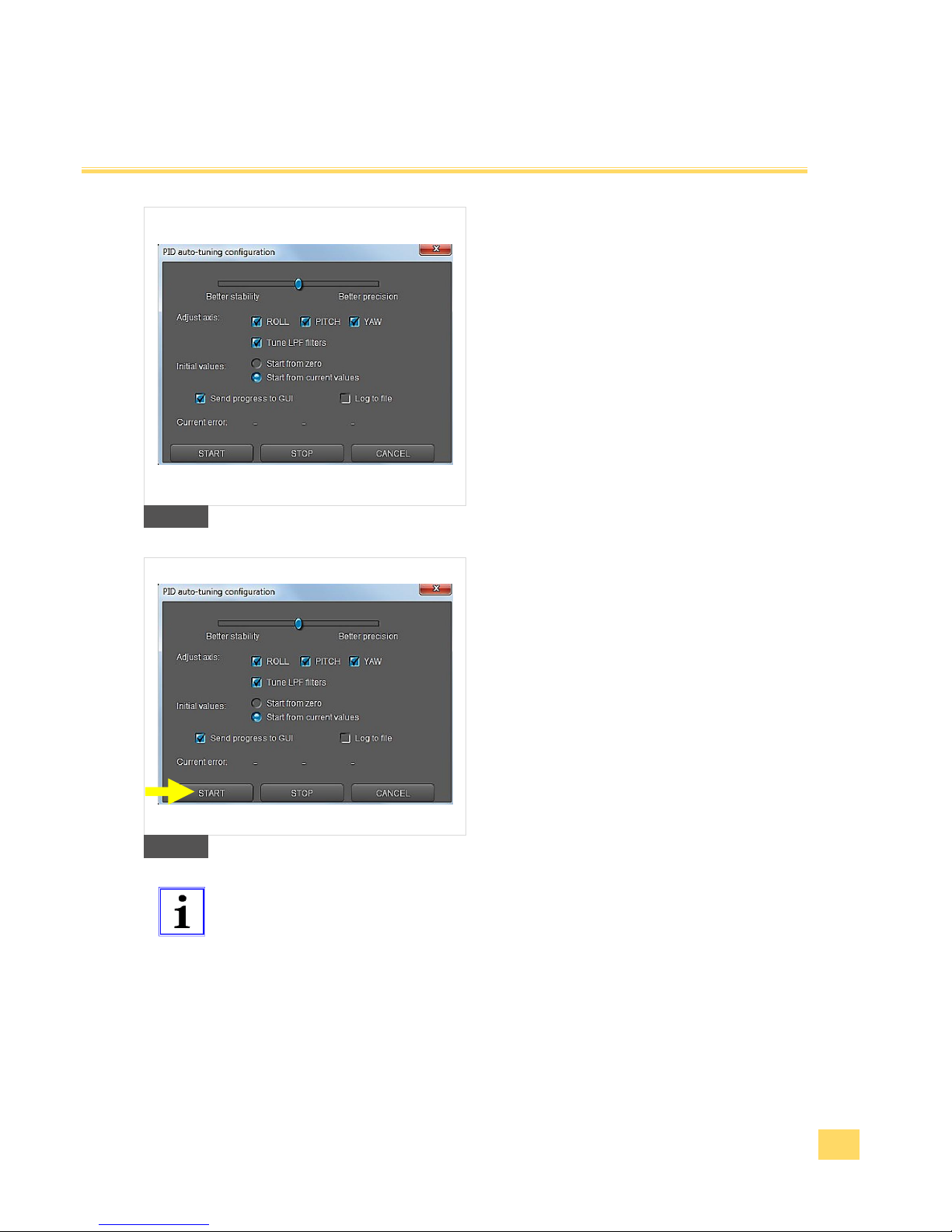
11. Mark in the displayed dialog the axis for
which you would like to adjust the PID
settings automatically. You can configure all
axes together or each axis separately.
Tuning axes separately can give better
result in some cases.
12. The slider at the top defines the target of
tuning. If it is closer to “Better precision”, the
auto-tuning program will try to achieve
maximum gain and keep it. If the slider is
closer to “Better stability”, the auto tuning
will try to find moderate gains where system
is more stable.
20
13. The auto-tuning program can automatically
set up Low-pass filter frequency. This filter
can significantly improve stabilization
quality in systems which have highfrequency resonances. Therefore mark the
check box „True LPF filters“.
14. Press the button „START“, to start the
automatic tuning process of the PID
parameters.
The auto-tune process needs ca. 1 minute.
21
Tip
Function! During the auto-tuning process, a controller sends a
command to rotate a camera through a small angle and detect optimum
characteristics of a system to minimize error of performing of this
command. Current value of the error is shown in dialog window (can be
opened as needed). The error value should be decreased during the
auto-tuning process. The process finishes when the error cannot be
decreased anymore. Also, you can stop the process by pressing “Stop”
button. Current optimum values will be saved into memory and shown
in GUI. The process will be emergency interrupted if a system is
unstable because of the tuning values. In this case, you should press
the menu button to restart a system and repeat the auto-tuning process
from the very beginning.
Page 32
IM_Rel.1.0.20160516-EN
32
Using the Software PC/MAC
5.4 Extended settings for advanced users
Caution
Property damage! The software SimpleBGC offers many versatile
possibilities. These extended functions are not within the context of this
introduction manual. For the use of this extended functionality we refer
you to the software user manual SimpleBGC 32bit 3-Axis. The
performing of functions which aren't described to your Pilotfly product
within the context of this instruction manual happens on your own
responsibility. We don't assume any liability for damages resulting from
it!
5.5 Filter setup
Warning
Injury danger! Before you change any settings, please read the
instruction manual completely and get familiar with all use and safety
instructions. Follow the notes and tips so that you can use the device
optimally.
Caution
Property damage! Do not change any setting if you are not aware of it.
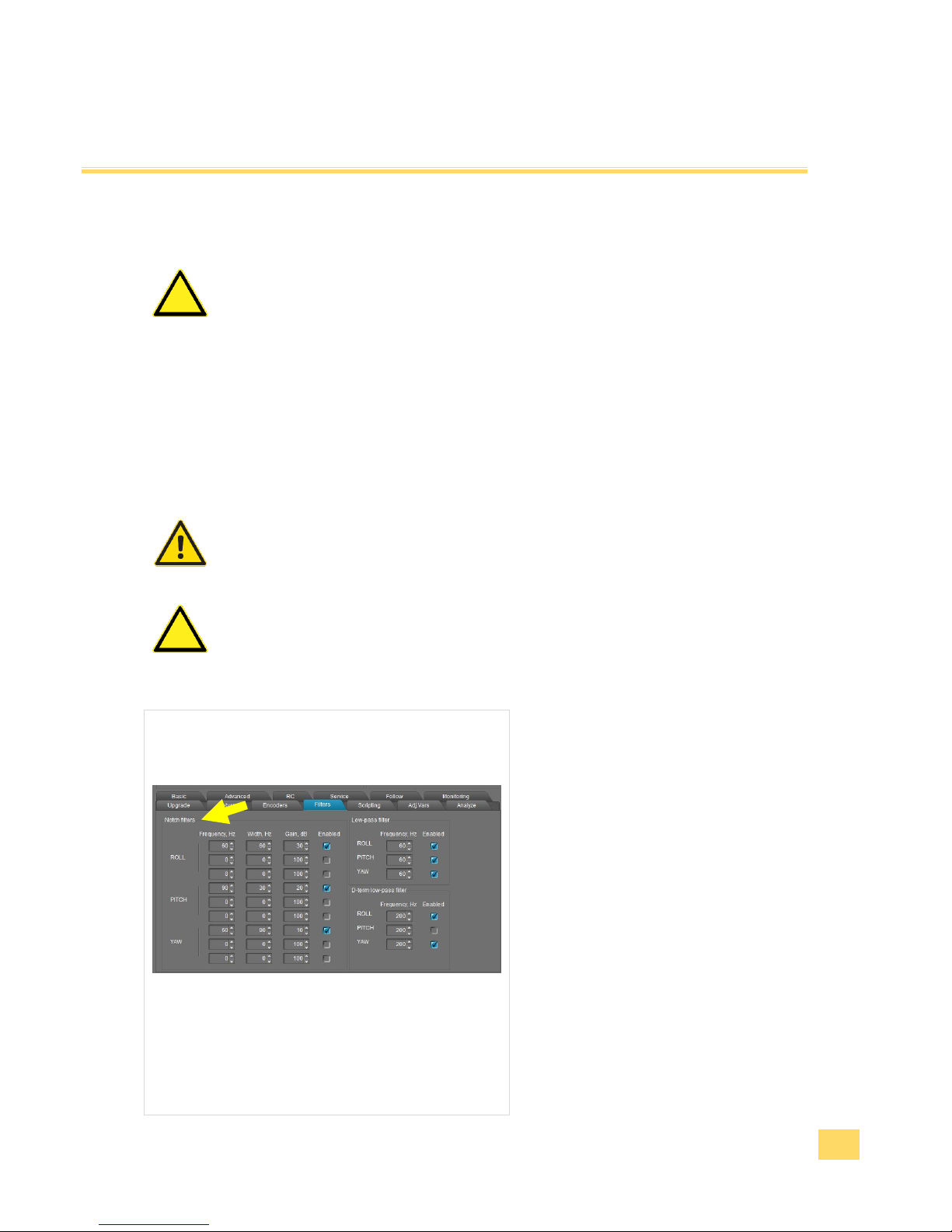
1. Notch Filters: This tab contains
settings to configure digital filters
that can help to improve the
quality of PID controller operation.
These filters can reject narrow
bandwidth (resonance). They can
help in cases when the system
has a pronounced mechanical
resonance. Raising the extant
feedback gain, oscillations will
appear first on the mechanical
resonance frequencies and does
not depend on variations of P,I,D
settings. In this case using one or
more notch filters can help to
increase feedback gain and get
more accurate and stable work of
the PID regulator. But this filter will
be useless if oscillations appear in
Page 33
IM_Rel.1.0.20160516-EN
33
the broad frequency range. In this
case it is better to use a low-pass
filter. With the parameter Gain you
can control the effect of the notch
filter. Set it equal to 100 to get
maximum effect, set it <50 to
compensate only light
resonances.
22
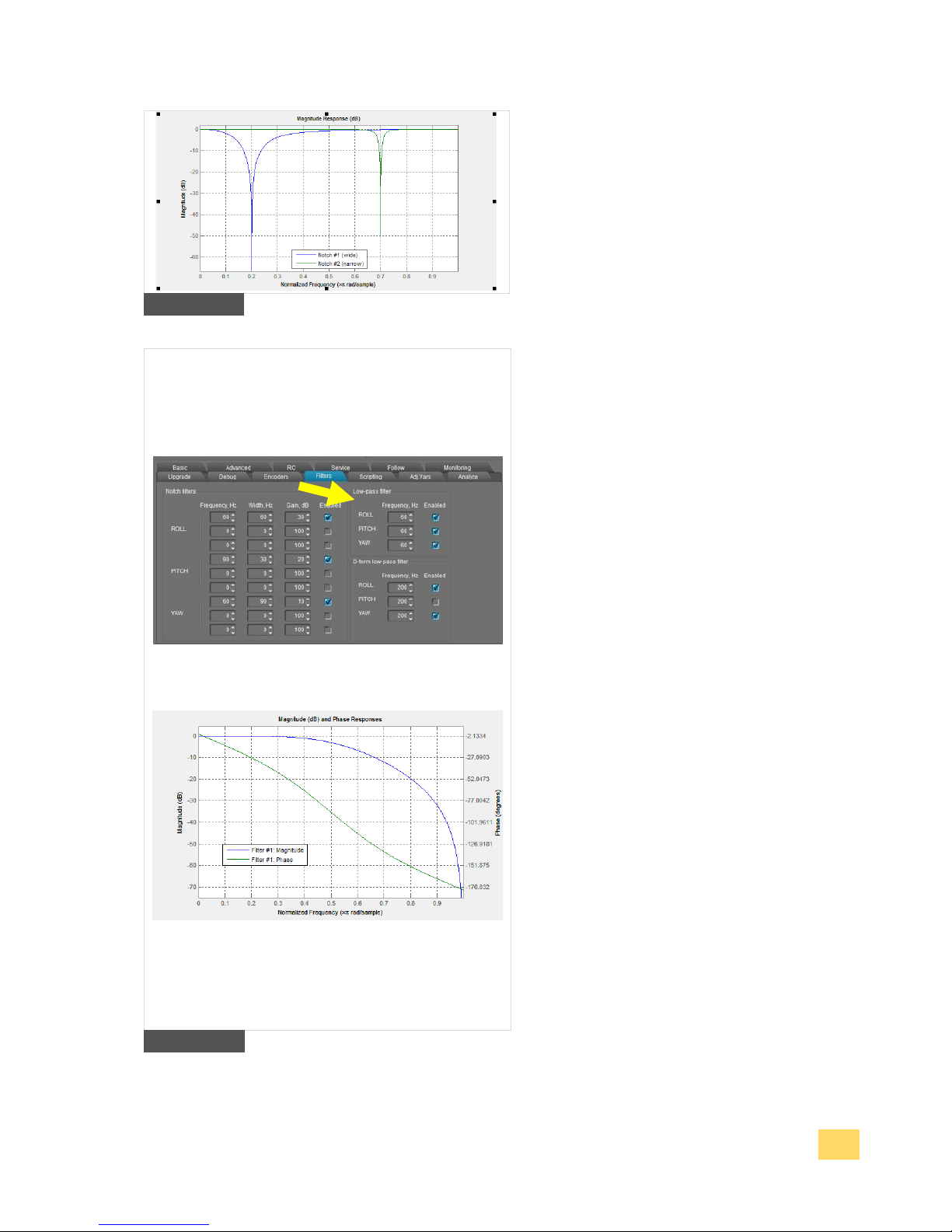
2. Low Pass Filters: It may be
necessary to apply this filter (low
pass filter) for large gimbals
(heavy cameras with high
moment of inertia) or for gimbals
with reduction gear. The working
frequency range for them are
lower than of the lightweight
gimbals. But factor D of PID also
increases feedback at higher
frequency. At high frequencies
the response of the mechanical
system is typically not sufficiently
precise because of many
reasons: highfrequency
resonances, propagation delay of
mechanical impact, nonlinearity
due to the backlash and friction,
and so on. Due to this the system
tends to self-excitation when gain
increases. A low-pass filter
reduces the gain at high
frequency and increases stability
of the system. But as drawback a
low-pass filter results in phase
delay which grows negative near
the crossover frequency and can
adversely affect the PID stability.
This is the reason for the
complexity of configuring this
filter, and its usage is not always
justified.
23
Page 34

IM_Rel.1.0.20160516-EN
34
Tip
Example for Filter adjustment:
Assuming, gimbal behavior is stable, but when camera tilts downward
60 degrees a strong vibration occurs and this effectively prevents an
increase gain of PID (which might otherwise be desired to improve
traction).
1. First detect which axis is causing vibration (most). To do this, in
the GUI go to the tab
“Monitoring” and switch on the following graphics:
RMS_ERR_R, RMS_ERR_P, RMS_ERR_Y.
Slowly tilt the camera downward until vibrations occur. The axis
which shows the greatest growth will show the primary axis
responsible. In the example it is RMS_ERR_P, the Pitch axis.
2. When in steady state vibration mode, look at frequency
indication: check another variable in the same tab: FREQ_P. It
shows the main frequency of vibration (in our case it has the
value 100). Another way is to use a spectroscope (for example,
an application for a smartphone that takes an audio signal from
mic), but this works only if the vibration is well-audible.
3. On the tab “Filters” fill out the parameters for the first notch filter
for Pitch axis: Frequency: 100, Width: 10, Gain: 80 and checkbox “Enabled” is switched on.
4. Write the parameters to board. Now try to re-establish the
oscillation. For our example the vibration has been significantly
reduced and its frequency shifted to 105Hz. Change the
frequency of the filter to 105 Hz. Now the frequency is shifted to
95 Hz. Set back value of the frequency to 100 and increase the
bandwidth to 20. Now vibration on this resonance frequency is
completely gone. Note, you need to set the bandwidth as
narrow as possible. Too broad bandwidth can result in
decreased PID efficiency.
5. Having closed one resonance, continue to increase gain of PID
(responsible for gain are the parameters P, D). Second
resonance occurs on frequency 140 Hz, when we tilt the
camera upward. Fill in values for the second notch filter for
PITCH axis to cancel this band too, the same way as above.
Page 35
IM_Rel.1.0.20160516-EN
35
Using the Android App
Warning
Injury danger! Before you change any settings, please read the
instruction manual completely and get familiar with all use and safety
instructions. Follow the notes and tips so that you can use the device
optimally.
Caution
Property damage! Do not change any setting if you are not aware of it.
6.1 Gimbal settings
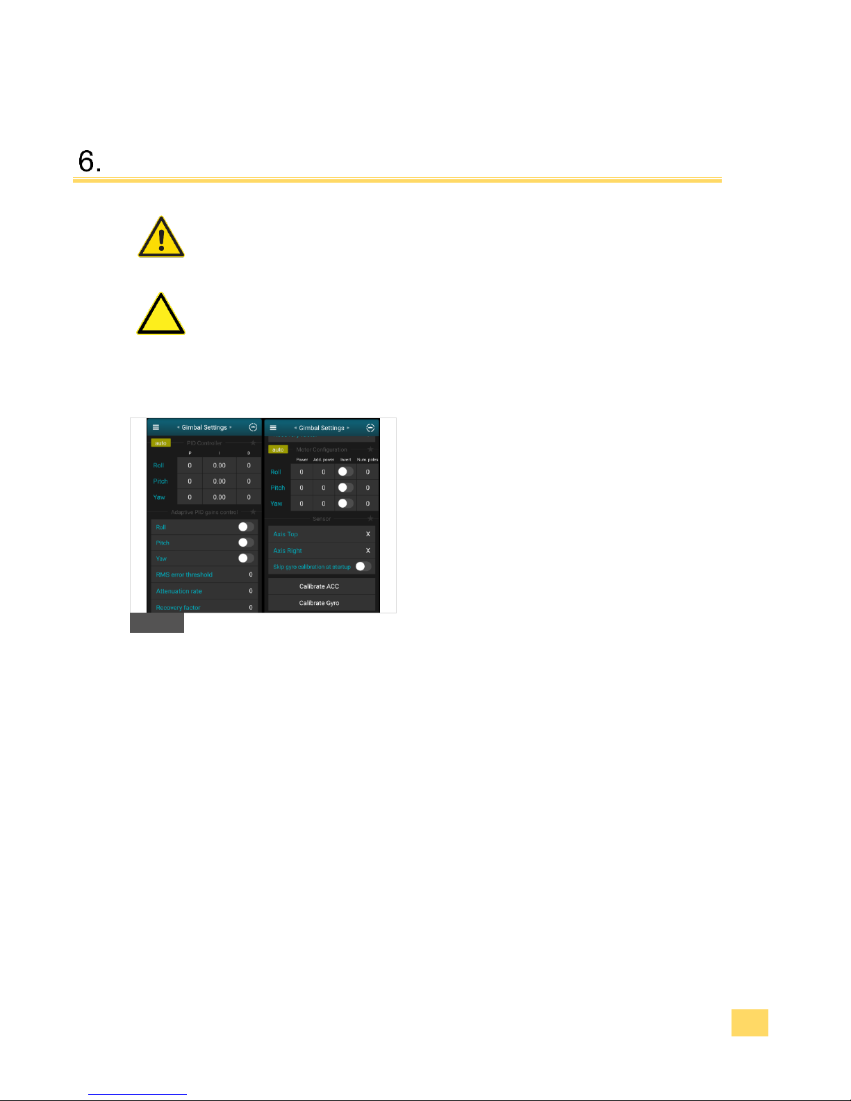
1. Set your PID values and Motor power values
2.5 Fine adjustment with help of the Software
SimpleBGC
F
Page 36
IM_Rel.1.0.20160516-EN
36
Using the Android App
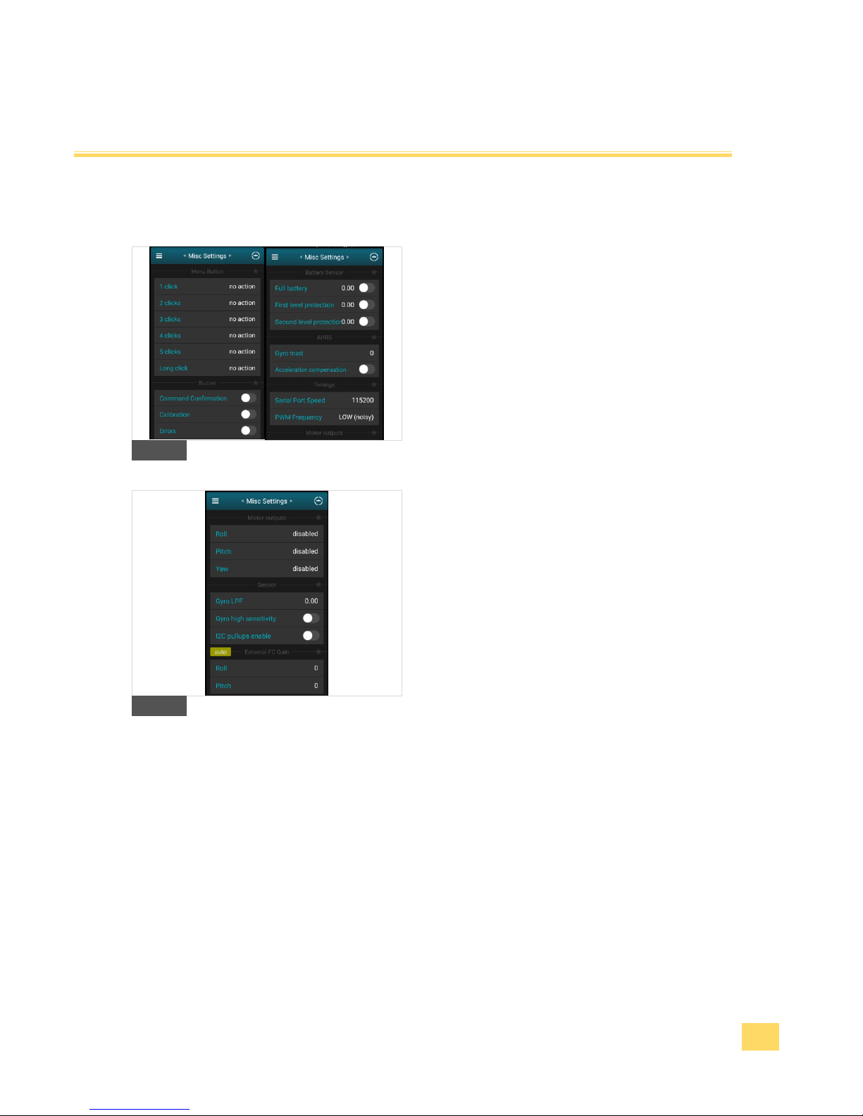
6.2 Misc settings
2. In the Misc Settings you are able to change the
command of the menu button, change sound
commands e.g. for errors or calibration or change
the battery values.
G1
G2
Page 37
IM_Rel.1.0.20160516-EN
37
Using the Android App
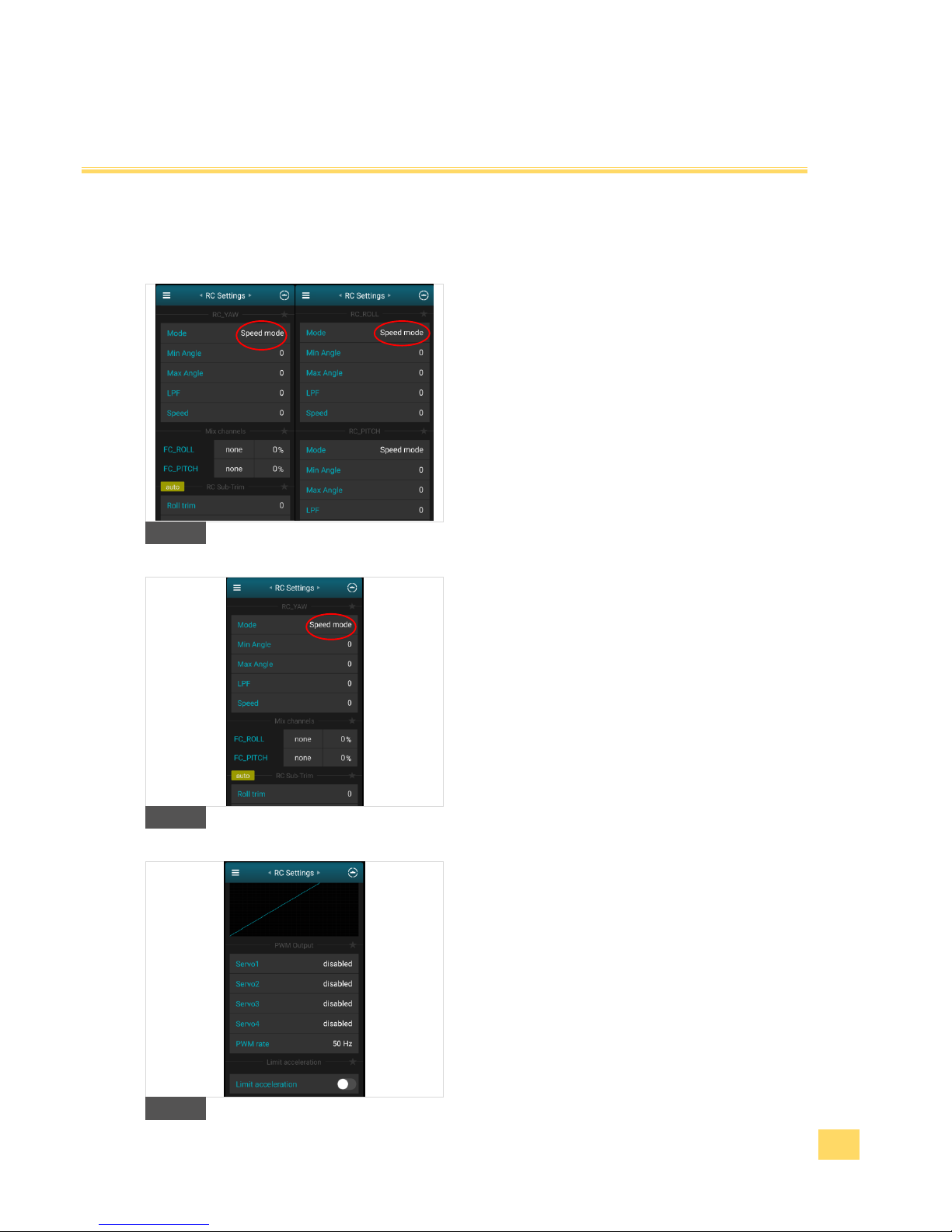
6.3 RC settings
3. In this area you are able to change the settings of
the joystick, change speed and angel of moving
area.
H1
H2
H3
Page 38
IM_Rel.1.0.20160516-EN
38
Using the Android App
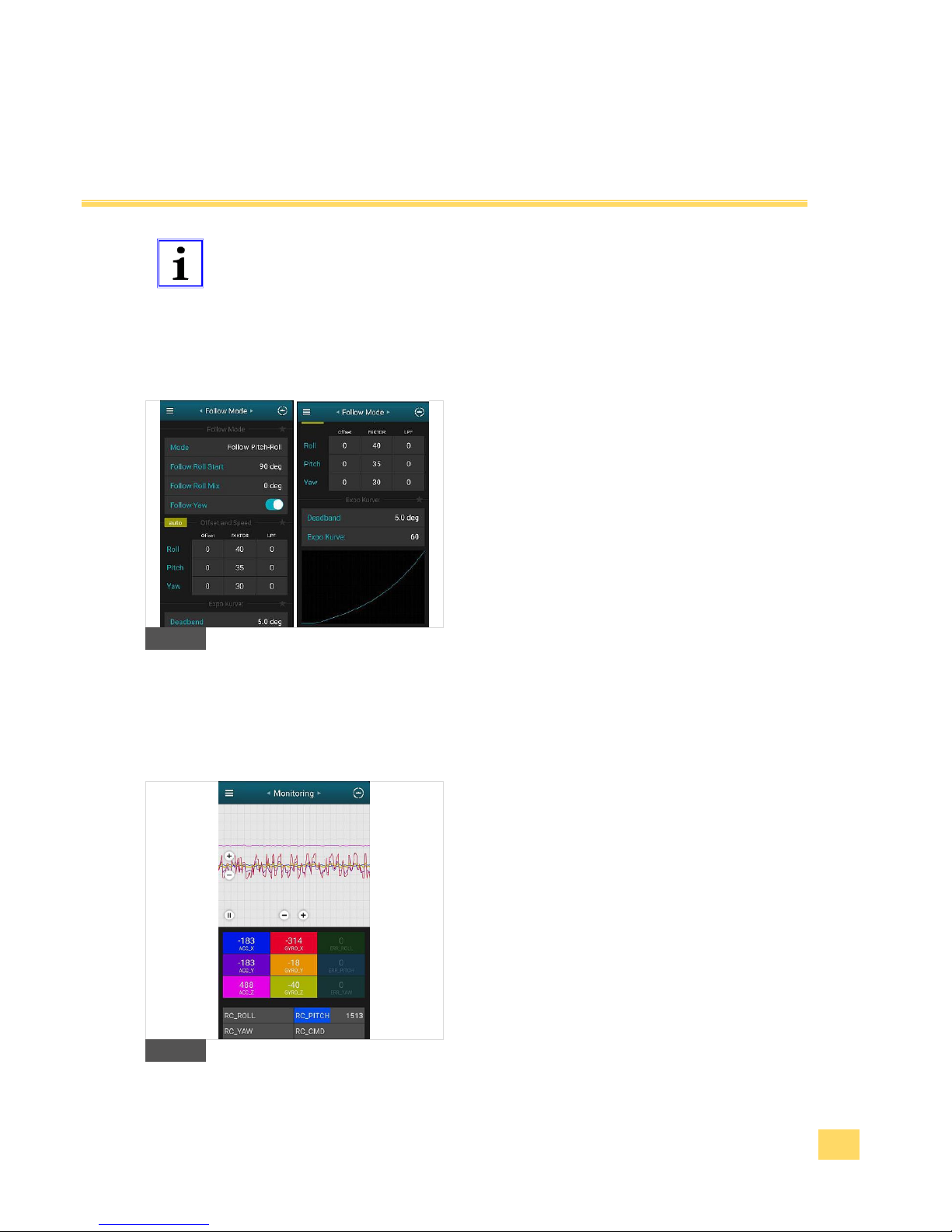
Tip
Function! If you experiencing any malfunction like that you are unable
to control the axes, please ensure that all RC Mode for each axes is set
to „Speed Mode“ instead of „Angle Mode“.
6.4 Follow mode
4. The Follow Mode is a special control mode that
makes the camera to „follow“ the movements. You
are able to change the settings to follow an
individual axes or change the speed of the
movement (Factor).
I
6.5 Monitoring
5. In this tab you can see the raw sensor data stream,
logical RC input levels and some debug
information. The monitor helps you to recognize in
a easy and fast way which motor/axis is vibrating.
I
Page 39
IM_Rel.1.0.20160516-EN
39
Using the Android App
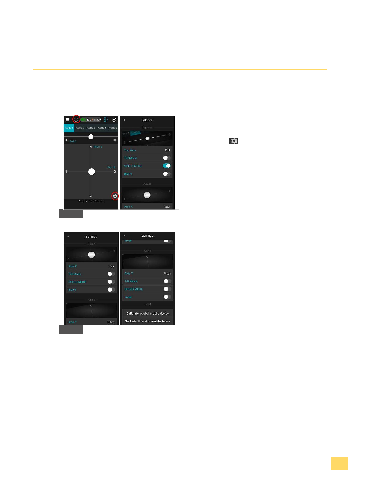
6.6 Control
6. The control panel enables you to control each axis
while moving the white cursor. In the sub menu
„Settings“ you are able to set which axis you
want to control on the touch panel or by moving the
smartphone (Tilt mode). The touch panel is
generally locked and needs to be activated first by
pressing the On/Off button on the upper left corner.
J1
J2
Page 40
IM_Rel.1.0.20160516-EN
40
Using the Android App
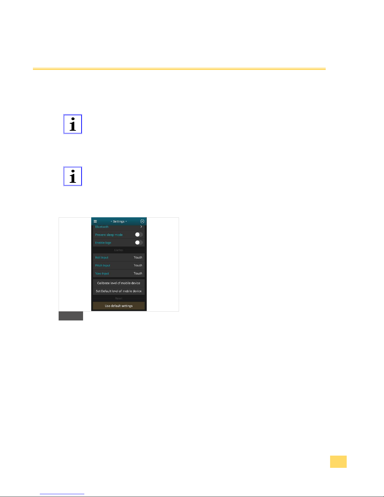
6.7 Settings
Tip
Function! Although you are able to „RESET“ your Gimbal. Please do
not use the „RESET“ Function otherwise you will delete your
default profiles which has been individually set by Pilotfly.
Please make a backup of each profile and save it to your computer
before you change any settings. 5. Using the Software PC/MAC
Tip
Legal hint! Pilotfly is license holder and partner of Basecam electronics
and is using their products and software, but is not responsible for any
software bug or malfunction of the provided software itself.
7. In the Setting menu you are able to set general
settings.
K
Page 41
IM_Rel.1.0.20160516-EN
41
Failure / Repair
Before you contact the service hotline Pilotfly-Service, please check by using the following table whether
you can solve the problem by yourself.
Warning
Injury danger! Do not carry out any repairs at the device by yourself.
Let the repairs at the device or at the cable only carried out by us
Pilotfly-Service. Extensive dangers for the user can arise from
improper repairs.
Roll motor is not horizontal levelled
Please make a Gyro & ACC calibration described in the user
manual.
The system starts vibrating while
moving the gimbal 90° forward
(brief case position)
Figure out which motor is causing the vibrations, in this case it is
most likely caused by the Pitch motor. If so decrease the D-value of
the Pitch slightly or change Motor power value of Pitch.
Pitch motor is suddenly missing
steps while moving up or down.
Ensure proper balancing of the camera. Increase motor power
of Pitch motor.
System starts vibrating while
moving
Figure out which motor is causing the vibrations, and decrease the
D-value of the related axes or change Motor power value of related
axes.
System is slightly drifting on the
yaw axis.
Poor Gyro calibration of Frame IMU.
Frame IMU needs to be re-calibrated.
Note: Frame IMU must be calibrated via SimpleBGC Software
installed on your PC, MAC or Android App (SimpleBGC32)
While moving forward (brief case
position) roll axis keeps not straight
and is moving slightly to left or
right.
Poor ACC & Gyro calibration of Camera IMU. Please make a Gyro
& ACC calibration described in the user manual.
Page 42

IM_Rel.1.0.20160516-EN
42
Failure / Repair
System is flattering in each
direction.
Wrong Motor setup. Hold the gimbal steady and start “Auto” for
the Motors in the Basic Tab of SimpleBGC GUI. Ensure that all
motor poles are set to “22”.
After that perform a calibration for Camera and Frame IMU
sensors.
Video: https://youtu.be/IxpdtzvjzoQ
System starts beeping
continuously.
Check battery level. Battery might be exhausted. Charge battery or
connect the external battery.
System starts beeping and battery
is fully charged.
Check battery level in the SimpleBGC GUI on the right bottom
corner.
Battery calibration might be necessary. Please follow the
instruction for battery calibration.
Roll and pitch not in level even
after ACC & Gyro calibration
Verify in the RC –Tab of the SimpleBGC GUI the “Initial angle” of
each axes. Initial angle need to be set to “0”.
Note: Operations like “Set tilt angles by hands”, “Swap RC Roll-
Yaw” or “Swap RC Pitch – Roll” will save their angles to this field,
too.
Page 43
IM_Rel.1.0.20160516-EN
43
Maintenance and care
The device is maintenance-free. In case of a reduction of the accumulator performance you can order a
replacement at our service Pilotfly-Service. Follow especially the safety instructions 1. 7 Precautions at
handling with Li-Po accumulators!
Clean the device with a dry antistatic cloth.
Warning
Injury danger! Switch off the device and unplug the plug from the
power socket before you clean it.
Caution
Property damage! Never use aggressive cleaning or abrasives.
Put out of operation, Storage, Transport
If you put the device out of operation temporarily, unplug the plug from the power socket and pack the
device and its accessories into the accompanying carrier bag.
At a longer removal from service you should charge the device from time to time as described in this
instruction manual 2.Setup and operating/2.3First steps.
Store the device at a cool dry place.
Page 44
IM_Rel.1.0.20160516-EN
44
Service
Nevertheless, if you should have problems with your product, please address your enquiry to
[email protected] (Taiwan) or [email protected] (Germany). We help you along willingly promptly and give
you information about the next steps.
Service Adresse Taiwan
Pilotfly Technology Co. LTD.
Jiafeng South Rd. No.118, 2F-2
Zhubei City, Hsinchu County 30271
Taiwan
Email: [email protected]
Service Adresse Germany
Pilotfly UG (haftungsbeschränkt)
Wendelsteinstr.12
86163 Augsburg
Deutschland
Email: [email protected]
Further useful links:
You receive the respectively current version of the instructions in the PDF format in the support area of the
Pilotfly UG on the web page under www.pilotfly.de.
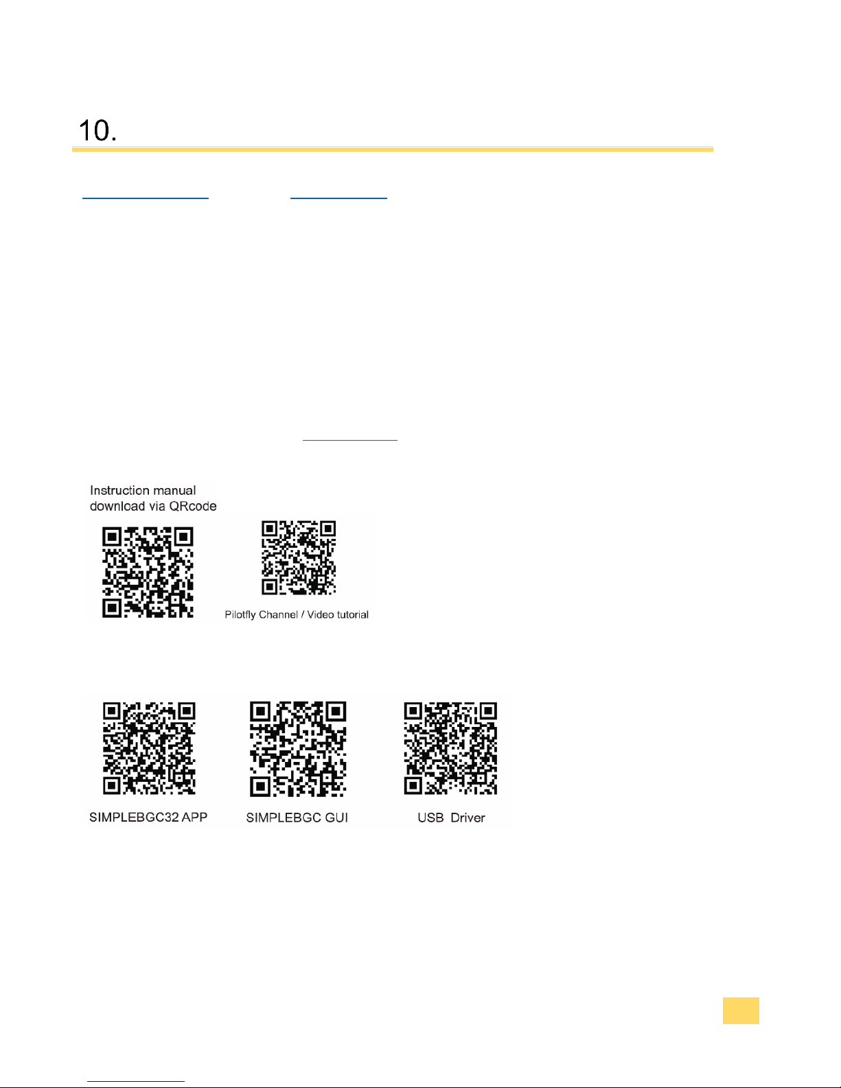
For quick access please use our QR-codes:
Software and driver download:
Page 45

IM_Rel.1.0.20160516-EN
45
IM_205.CCF.20160410-EN
 Loading...