

Page 1
2
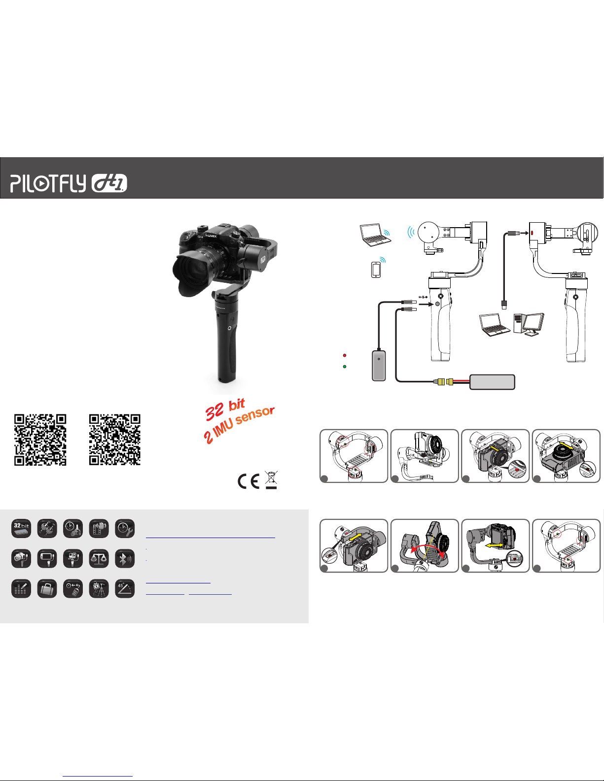
2. 1. 3. 4.
6. 5. 7. 8.
2
4S 14.8V LiPO
16.8V 1ACharger
DC-I N
Parameters by SimpleBGC GUI
Micro USB
PC/NB
CONNECTING
LEDRED:
Charging
LED Green:
Charged
Connect to extender battery
Not included
Parameters by SimpleBGC GUI
Parameters & Remote control
by SimpleBGC Mobile APP
(Google play)
Bluetooth
ID: PILOTFLY
Password: 1234
CAMERAINSTALL&BALANCE
Attach the camera to the
PILOTFLY H1 and fix it with the
1/4 screw.
Shift the camera to balance
and adjust the tilt axis and
tighten the 1/4 screw.
Adjust tilt axis (vertical).
Rotate the tilt axis that the
camera lens is pointing straight
up. Shift the camera till it is
balanced and tighten up the
marked screw.
Adjust tilt axis (vertical).
Rotate the tilt axis that the
camera lens is pointing straight
up. Shift the camera till it is
balanced and tighten up the
marked screw.
Balancing the Pan:
Hold the device as shown on
the picture and check the
balance of the pan axis.
Shift the L-arm of the pan axis
then tighten up the marked
screws.
Ensure proper fixation and
double check all screws again.
Tighten up if necessary.
Loosen up all marked M4 screws.
Full manual download from Qrcode
English 繁體中文
QuickGuide Handheld 3AXIS Stabilizer for Mirrorless camera
PILOTFLY H1 Plus
Heigh t: 310 mm
Width :150 mm
Depth : 150 mm
Weight : 890 g
Camera tray size
Heigh t: 110 mm
Width : 140 mm
Maximum supported weight
Camer a : 1500 g
Maximum offset
On pan: 3 55°
On tilt : 355° , +/ -180° d uring w ork
On roll : 355° , +/ -60° du ring wo rk
Power
Power s upply : Bulid -in Rec harg eable L ithiu m Polym er 4-ce ll
14.8V 1 800mA h batte ry
Opera tion ti me: 60 to 2 10 minu tes
(depe nds on se tting s and act ual ca mera we ight)
Electronics
Main bo ard: Cu stom Alex Mos 3-a xis Si mpleB GC 32bi t
Dual IM U senso r
Conne ctivi ty: Min i-USB
Contr ol Mode : Defau lt 3 use mo de
Facebook:
www.facebook.com/pilotflytech
Technical support via e-mail:
info@pilotfly.de
yanherlin@gmail.com
No charge function
SE
Page 2
QuickGuide
This is a sophisticated cinema product. It must be operated with caution and common sense and requires some basic
mechanical ability. Failure to operate this product in a safe and responsible manner could result in injury or damage to
the product or other property. This User Guide contains instructions for safety and operation. It is essential to read the
entire User Guide and follow all instructions and warnings in the manual, prior to setup or use, in order to operate the
PILOTFLY H1 correctly and avoid damage or injury.
PILOTFLY CO. LTD has made every effort to provide clear and accurate information in this User Guide, which is
provided solely for the user’s knowledge. While thought to be accurate, the information in this document is provided
strictly “as is” and PILOTFLY CO. LTD will not be held responsible for issues arising from typographical errors or user’s
interpretation of the language used in this User Guide that is different from that intended by PILOTFLY CO. LTD.
PILOTFLY CO. LTD reserves the right to revise this User Guide and make changes from time to time without obligation
to notify any person of such revisions or changes. In no event shall PILOTFLY CO. LTD, its employees or authorized
agents be liable for any damages or losses, direct or indirect, arising from the use of any technical or operational
information contained in this document.
DISCLAIMER
All instructions, warranties and other documents are subject to change at the sole
discretion of PILOTFLY CO. LTD. For up-to-date product literature,
visit www.pilotfly.com.tw . chnical or operational information contained in this document.
NOTICE
Qty 1 - PILOTFLY H1 Handheld Stabilizer
Qty 1 - Charger
Qty 1 - Smartphone holder
Qty 1 - M4 Hex wrench
Qty 1 - Battery extention cable (XT60)
BOX CONTENTS
First steps:
1. Follow the instruction how to mount the camera on the Gimbal.
2. Ensure that all three axes are well balanced; refer to the video how to balance the gimbal correctly.
3. Hold the device with mounted camera straight up and power on the system (red button)
4. Initialization of the gimbal will be indicated by the beep tone sequence.
a.System is ready to use – Follow mode is active (Modes will be indicated by the LED flash light.)
i.Mode 1: Follow Mode – Green LED is flashing once
ii.Mode 2: Tilt Lock Mode – Green LED is flashing twice in a row
iii.Mode 3: Lock Mode – Green LED is flashing 3 x times in a row
.
5 Make some moves with the gimbal in each direction to see whether it works or not.
If not, figure out below which problem are you facing in:
1
Roll motor is not horizontal levelled
Please make a Gyro & ACC calibration
described in the user manual.
2
The system starts vibrating while
moving the gimbal 90° forward
(brief case position)
Figure out which motor is causing the vibrations, in this case it is most likely
caused by the Pitch motor. If so decrease the D-value of the Pitch slightly or
change Motor power value of Pitch.
3
Pitch motor is suddenly missing steps
while moving up or down.
Ensure proper balancing of the camera.
Increase motor power of Pitch motor.
4
System starts vibrating while moving
Figure out which motor is causing the vibrations, and decrease the D-value of
the related axes or change Motor power value of related axes.
5
System is slightly drifting on the yaw
axis.
Poor Gyro calibration of Frame IMU.
Frame IMU needs to be re-calibrated.
Note: Frame IMU must be calibrated via SimpleBGC Software installed on
your PC, MAC or Android App (SimpleBGC32)
6
While moving forward (brief case
position) roll axis keeps not straight and
is moving slightly to left or right.
Poor ACC & Gyro calibration of Camera IMU. Please make a Gyro & ACC
calibration described on item xx
7
System is flattering in each direction.
8
System starts beeping continuously.
Check battery level. Battery might be exhausted. Charge battery or connect
the external battery.
9
System starts beeping and battery is
fully charged.
10
Roll axes hanging at one side, while
turning around 180° the Roll axis is in
level.
11
Roll and pitch not in level even after
ACC & Gyro calibration
Verify in the RC –Tab of the SimpleBGC GUI the “Initial angle” of each axes.
Initial angle need to be set to “0”.
Note: Operations like “Set tilt angles by hands”, “Swap RC Roll-Yaw” or
“Swap RC Pitch – Roll” will save their angles to this field, too.
1. Invert Mode: Turn the camera around, that handle is above the camera, place camera in position and power on
device. System will auto detect invert mode.
2. Swap RC Pitch Roll: You can use this mode as Mode 4 (Profile 4). Activate this at Service Menu Menu button
first. While pressing the Mode button 4 times you are able to switch the RC control for Pitch to Roll axes and vice
versa. Changes like this will change the initial angle in the RC tab. Please refer to item 11 in the above table.
How to reset and re-calibrate IMU sensors. How to calibrate the battery.
Video
Wrong Motor setup. Hold the gimbal steady and start
“Auto” for the Motors in the Basic Tab of SimpleBGC
GUI. Ensure that all motor poles are set to “14”. After
that perform a calibration for Camera and Frame IMU
sensors.
Check battery level in the SimpleBGC GUI on the right
bottom corner. Battery calibration might be necessary.
Please follow the instruction for battery calibration.
Camera IMU Sensor not in level. Remove IMU sensor
and add a small adhesive tape at the screw hole side.
Assemble it again to the Gimbal and perform a ACC &
Gyro calibration again as described in the user manual.
Video
Additional documentation:
First steps Video
PID & Power Setting sheet
Save/Backup profile before change any setting.
SE
 Loading...