

Page 1

Trainer Assembly
Manual
www.pilot-rc.com
-Pilot Trainer- 1
Page 2
-Pilot Trainer- 2
Page 3
-Pilot Trainer- 3
Page 4
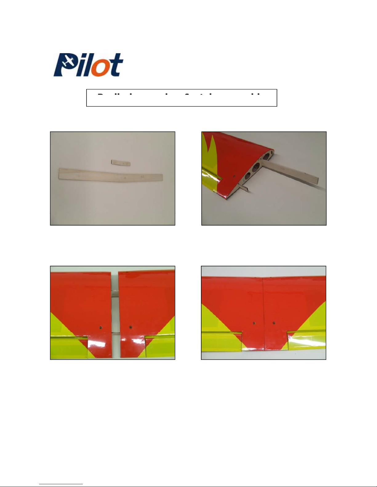
-Preliminary wing & stab assembly-
1-) Locate both Plywood wing
joiners (Large and small one)
2-) Insert both wing joiners inside
one wing panel.
3-) Slide the other wing panel
over the plywood joiners.
4-) Bring both wing panels
together and verify for proper fit.
-Pilot Trainer- 4
Page 5
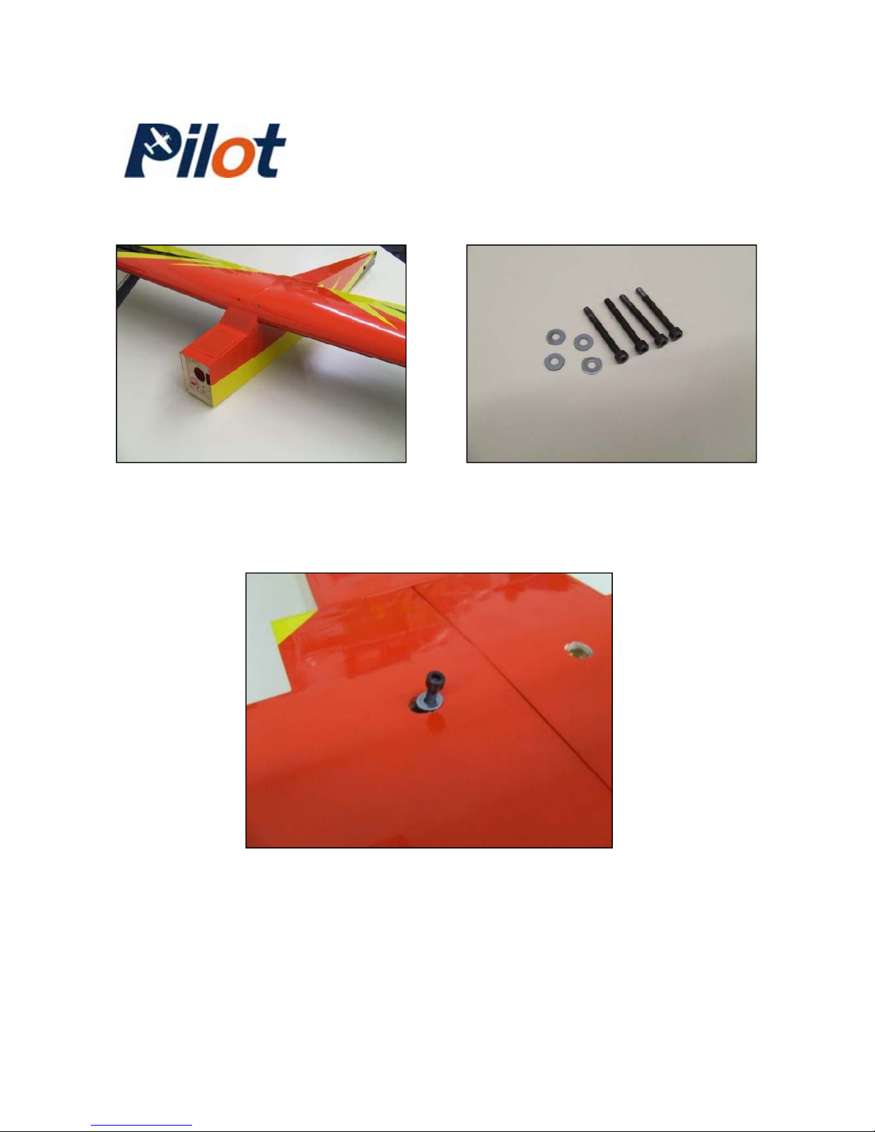
5-) Fit the complete wing over 6-) Locate the 4 wing mounting
the fuselage as shown. screws and washers from the
enclosed hardware bag.
7-) Insert the 4 screws and washers in the pre-cut holes in the wing,
securing them into the pre-installed “Blind-Nuts” inside the fuselage.
-Pilot Trainer- 5
Page 6
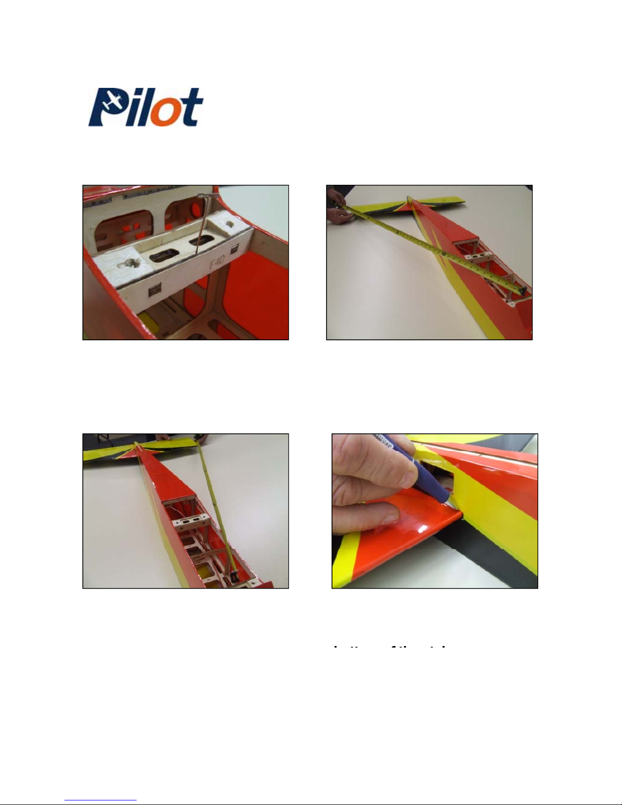
8-) Measure the width of the
fuselage and insert a “modeling
pin” in the middle as shown.
9-) Insert the stab into the
fuselage. Measure from the pin up
to the stab tip. See next picture.
10-) Measure from the other
side and equally space the stab
onto the fuselage.
1 1-) Once the stab is centered,
draw a line on both side of the
stab as shown, both top and
bott
om of the stab.
-Pilot Trainer- 6
Page 7
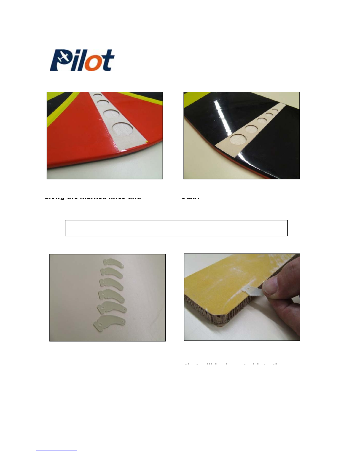
13-) Repeat on the bottom of the
12-) Using a modeling knife, cut
stab.
along the marked lines and
remove the covering.
-Elevator control horn assembly-
15-) Using a sanding bar, sand
the horn section (on both sides)
14-) Locate the control horns for
the hardware bag.
that will be i
nserted into the
elevator for better glue adhesion.
-Pilot Trainer- 7
Page 8
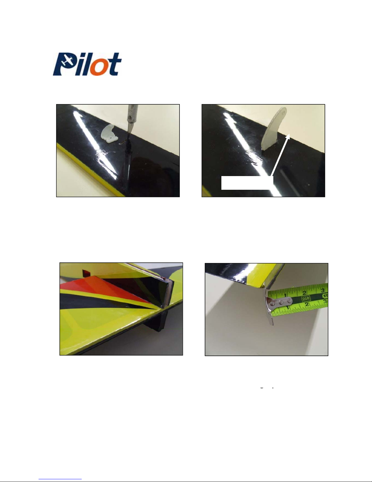
16-) Locate the pre-cut slot on the 17-) Mix some “30-minute epoxy”
-FRONT-
bottom of the elevator and cut to
remove the covering.
and glue the elevator horn. NOTE:
The horn must face the front of the
leading edge of the elevator .
18-) Apply 30-minute epoxy to
both the stab and fuselage
sections and slide the stab into
19-) Before the epoxy cures, align
the stab by equally measuring
from each win
g
tips as reference.
position.
gp
-Pilot Trainer- 8
Page 9
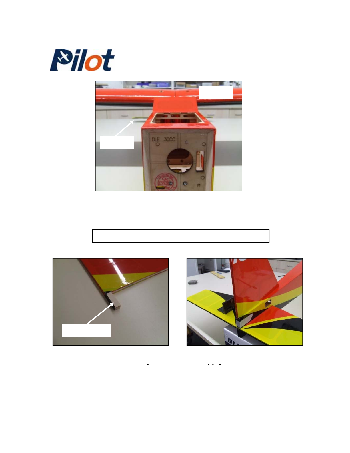
-
-
-WING-
STAB
20-) While the epoxy is curing, align the stab to the wing by
looking from the front of the fuselage. Adjust if required.
Tail group assembly
21-) Cut and remove the covering
from the bottom of the fin
p
ost.
22-) Mix some 30-minute epoxy
and apply to both the fin and
-FIN POST -
p
pp y
fuselage inner sections. Secure
with masking tape.
-Pilot Trainer- 9
Page 10
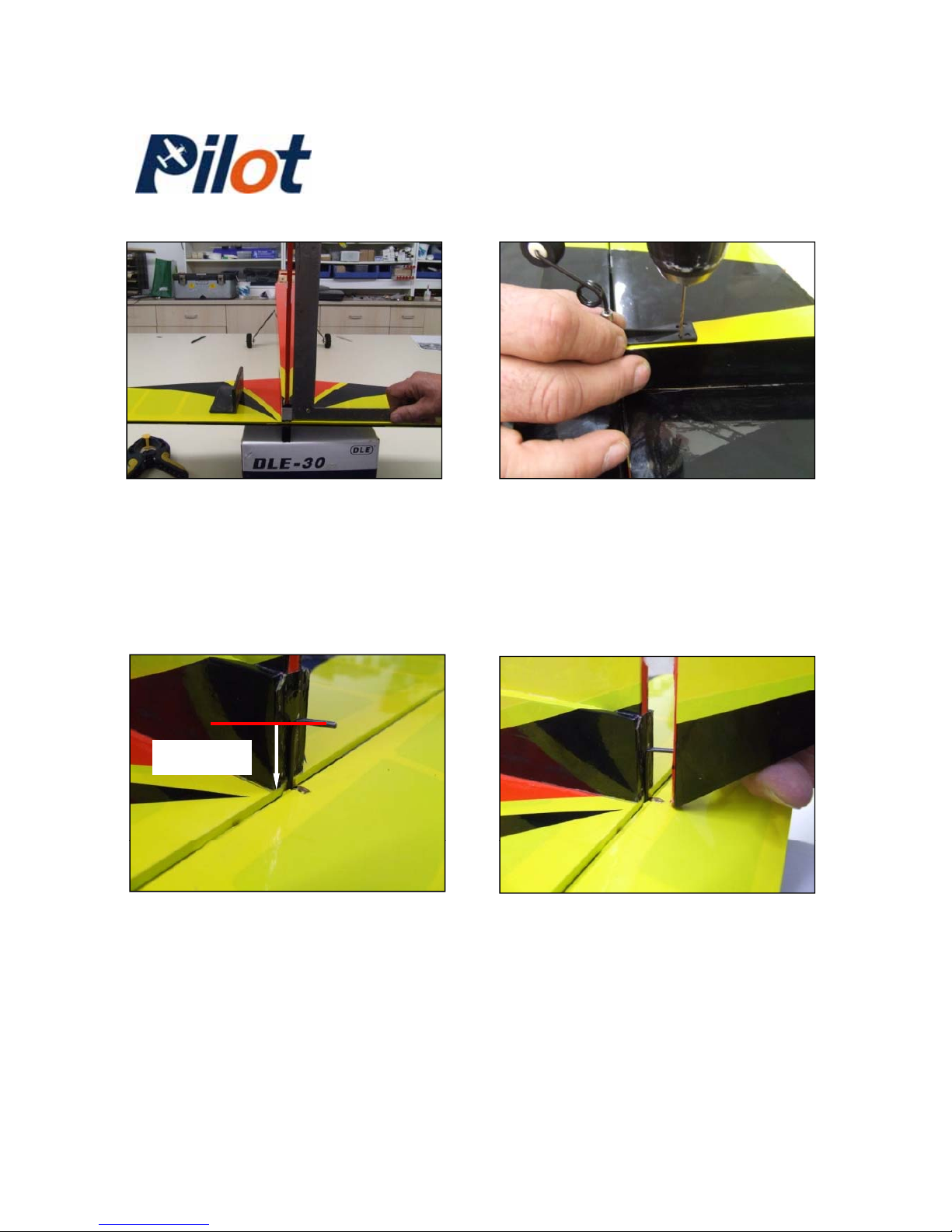
23-) While the epoxy is curing,
align the fin to the stab at 90-
24-) Set the tail wheel bracket
over the fuselage as shown. Drill
degrees. small holes and secure with the
supplied wood screws.
21mm
25-) You will need to make a 90degree bend into the steel wire,
21mm from the top of the stab.
26-) The rudder as a pre-cut slot
in it’s leading edge. Cut and
remove the covering and trial fit
NOTE: The bend must be parallel
to the rubber tail wheel.
the steel wire into it
.
-Pilot Trainer- 10
Page 11
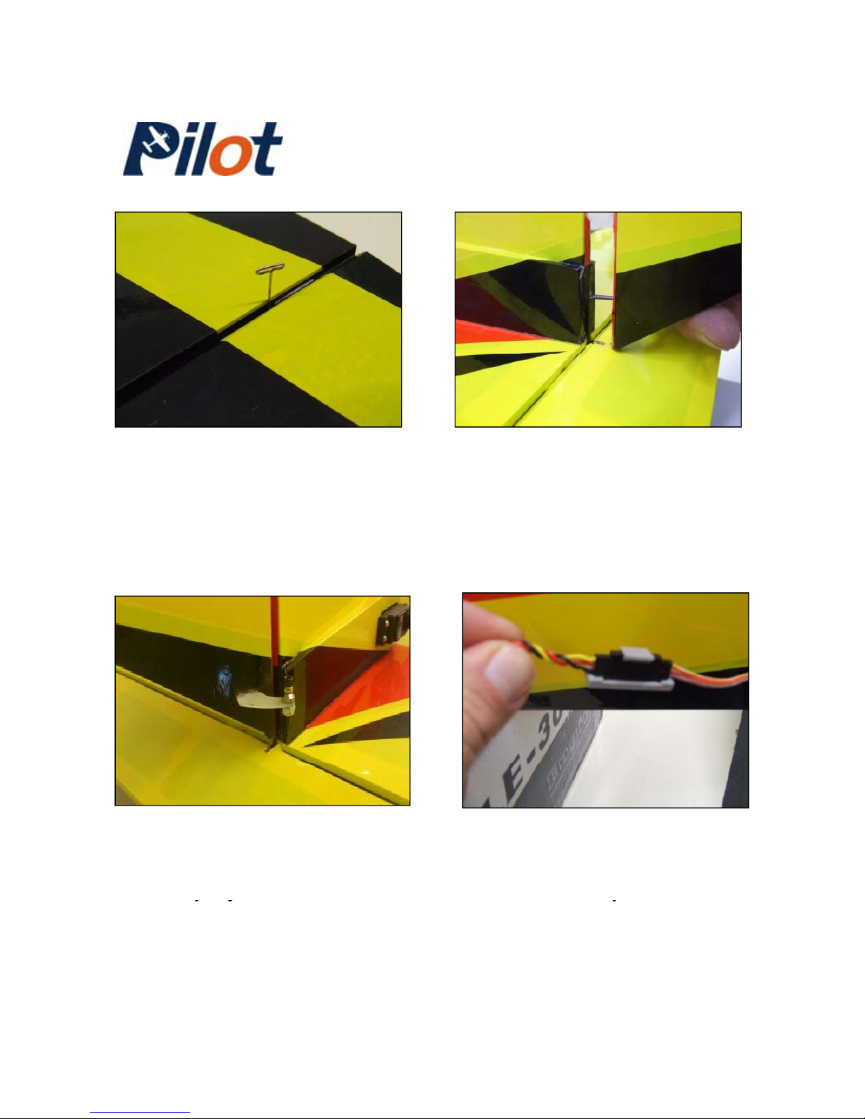
27-) Insert a pin in the center of
each hinges. Insert the hinges in
28-) Repeat for the rudder but also
mix some 30-minute epoxy to
both elevator and stab and push
them in position as shown. Then,
apply a few drops of “Thin C.A” to
each sides of the hinges.
bond the steel wire into the rudder
.
28-) Repeat the elevator horn
installation process for the rudder
and bond the rudder horn with 30minute e
poxy
.
29-) Locate on the fuselage the
rudder and elevator servo openings
and cut/remove the covering. Plug
one servo to each
p
re-installed servo
py
p
leads and secure with the supplied
servo retainer clips.
-Pilot Trainer- 1 1
Page 12
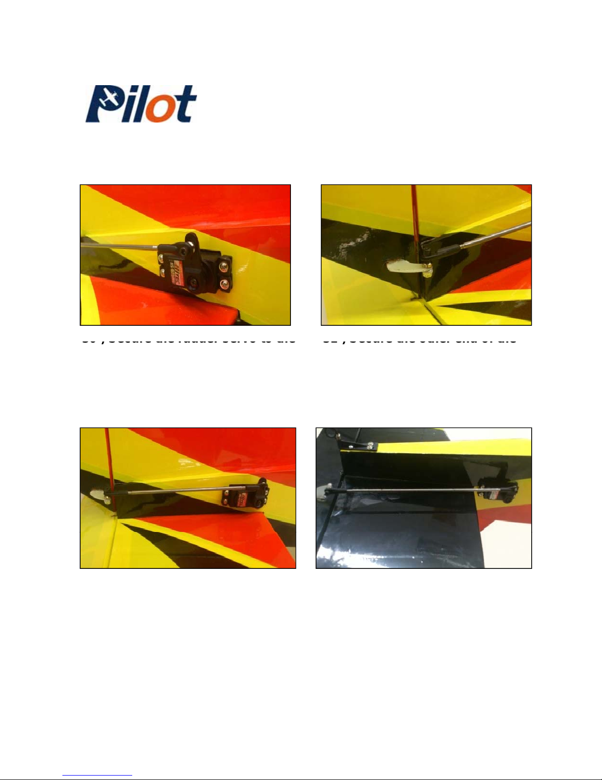
-
-
31
) Secure the other end of the
rudder pushrod to the rudder horn.
30
) Secure the rudder servo to the
fuselage with screws and connect
the rudder pushrod from the
hardware bag (short one) to the
servo arm.
32-) Completed rudder pushrod
installation shown here for
reference.
33-) Repeat the same process for
the elevator servo. Use the
remaining long pushrod from the
hardware bag
.
-Pilot Trainer- 12
Page 13
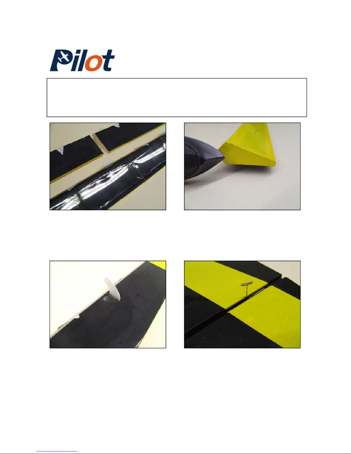
-
-
Final wing assembly
Note: This wing is built with full-span ailerons or with flaps. The
procedure below shows how to install flaps.
35-) If you choose to do so, simply
cover the exposed ends of the
ailerons/flaps with the supplied
covering material.
34-) In the middle of both ailerons,
there is a location to “split” the
ailerons in half. Cut into that
section to separate the ailerons
from the flaps
.
36-) Locate the slots in the
37-) Like the rudder and elevator
ailerons/flaps and bond a control
horn into each slots using 30minute epoxy.
hinges, repeat the same procedure
for bonding both the flap and aileron
hinges.
-Pilot Trainer- 13
Page 14
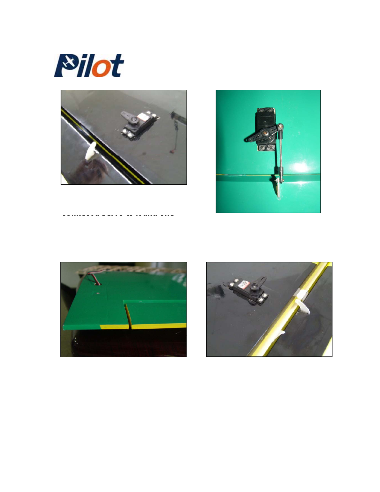
38-) Locate the pre-installed servo
lead extension for the aileron and
39-) Connect both flap and aileron
servos to their respective horns
using the supplied small
pushrods.
connect a servo to it and one
servo retainer clip. NOTE: You will
need two optional servo lead for
the flap servos.
40-) All servo lead extensions
should pass through the pre-cut
holes in both wing panels as
41-) Repeat the same procedure
for the flap servos.
shown
.
-Pilot Trainer-
14
Page 15
-
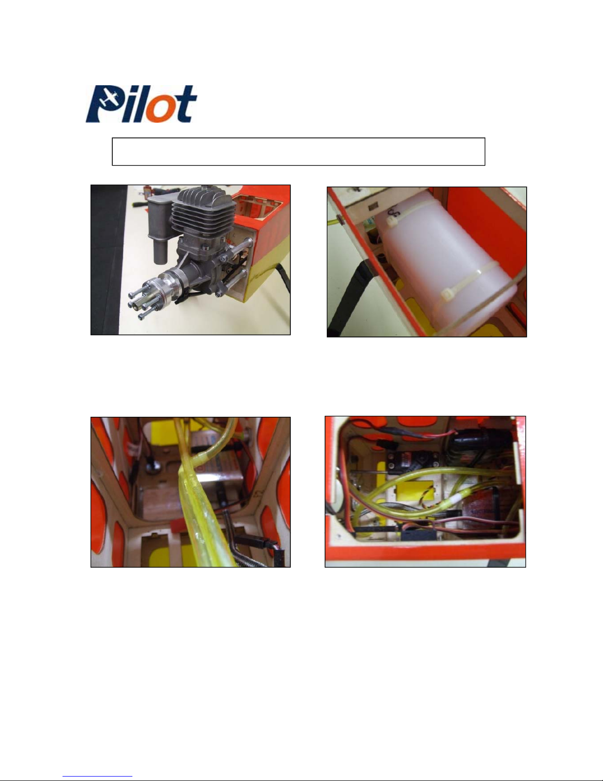
Engine and fuel tank installation
-
43-) Install the fuel tank and
secure it using the supplied
plastic “Tie-Wraps” as shown.
42-) DLE 30
cc engine. Dr
ill th
e
laser-marked holes on the firewall
and install it using the stand-off’s
that came with your engine.
45-) Install the throttle servo first
and pushrod. The ignition battery
should be installed using plastic
“
”
44-) Install the engine ignition
module. Secure it with plastic TieWraps” to make sure it will not
tie
-
Wraps to secure it in place
.
Secure the removable hatch with
two wood screws.
move inside the fuselage
.
-Pilot Trainer- 15
Page 16
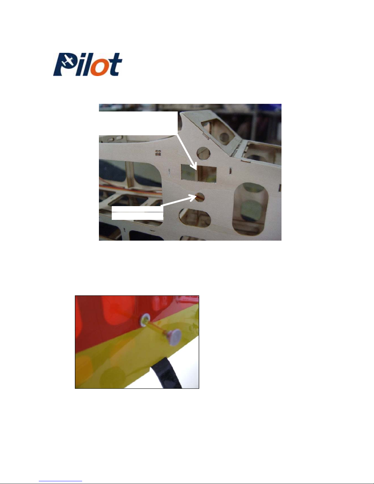
Ignition/Receiver
switch
46-) Ignition, receiver switches and fuel dot. Referring to the above
drawing, cut the covering over the openings for the 2 switches (Right
Fuel dot
and Left sides) and 1 fuel dot
.
47-) The fuel dot receptacle is
fitted to the fuselage . You
have to unscrew the fuel line
plug to fill the fuel tank
.
(Picture for reference only)
-Pilot Trainer- 16
Page 17
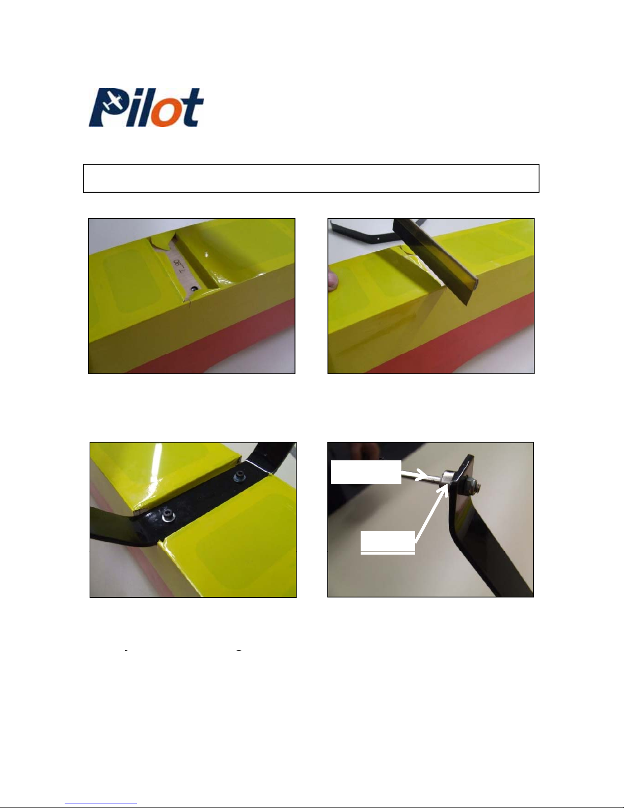
-Main landing gear installation / Tail dragger version-
48-) Cut the covering from the
first gear location (near the
firewall)
49-) Using a small saw, cut into
both fuselage sides to clear the
gear.
Collar
Axel
50-) Secure the main gear with
the supplied screws and washers
from
y
our hardware bag.
51-) Install one wheel axel on
each sides of the gear and
insert one wheel collar over the
yg
axel as shown.
-Pilot Trainer- 17
Page 18
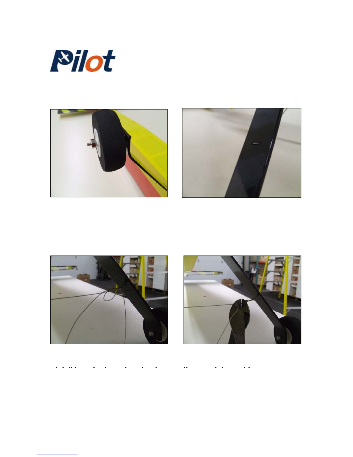
52-) Position the wheels and
secure with another wheel collar.
NOTE: The following pictures
describe the installation of the
optional steel stiffening brace.
53-) Gear stiffening brace. There
are two holes per gear sides, near
the middle. Insert in a “U” shape
the supplied steel cable from your
hardware bag.
54-) Using one Brass sleeve,
pass the steel cable in a “loop
55-) Crimp the Brass sleeve
against the steel cable and cut
style” in order to make a knot
into it.
th
e remaining cable.
-Pilot Trainer- 18
Page 19
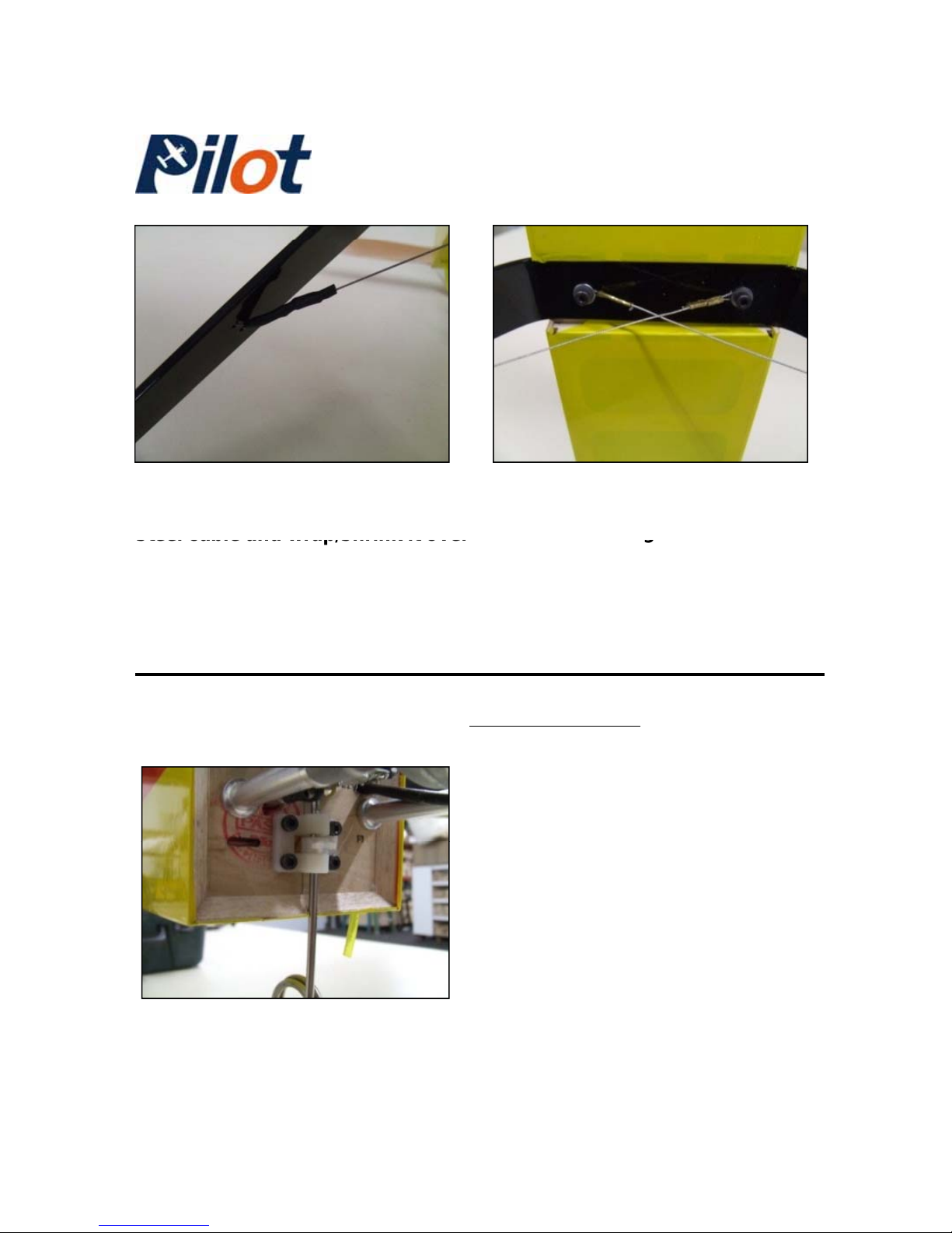
56-) Slide a piece of “Heat-Shrink”
tubing over the loose end of the
57-) Slide another Brass sleeve over
one end of a steel cable and “loop” it
under the main
g
ear screw washer
steel cable and wrap/shrink it over
the Brass sleeve. Repeat for the
other side.
g
and then, crimp the Brass sleeve.
Repeat for the other side. NOTE: Lift
the fuselage off from the main gear
before crimping the Brass sleeves.
T rike gear option:
-Secure the Nylon nose gear support
with four screws through the pre-cut
holes in the firewall.
-
Slide the steel nose gear through the
Nylon support and the Nylon steering
arm. Connect the steering arm to a
servo inside the fuselage front section
-Tighten the set-screw in the steering
arm directly over the “flat” section of
the steel nose gear.
-Pilot Trainer- 19
Page 20
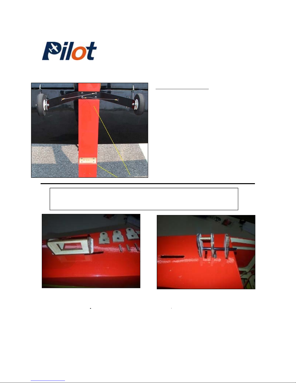
T rike gear option:
-The main gear is positioned
rearward, under the wing.
-There is a cavity for it recessed into
the fuselage, the same dimensions
as for the Tail dragger version.
-Simply cut the covering and install
the main gear , as previously
described.
-Optional Tow hook Release Mechanism-
(Optional items / available separately from Pilot RC)
1-) Assemble the small servo tray
as shown. This
p
art will be
2-) Dry fit the two parts F51, one
F51A
,
one Brass sleeve and one
p
bonded latter inside the top
section of the fuselage.
,
Black tube. NOTE: Part F51A goes
towards the front of the fuselage.
-Pilot Trainer- 20
Page 21
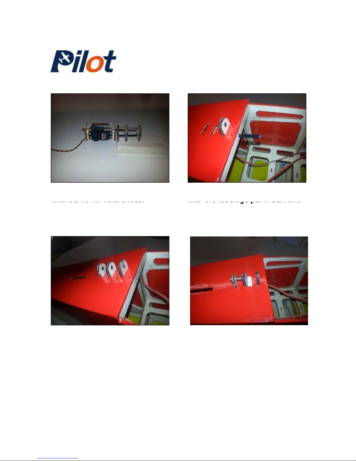
2-) Overall finished assembly
3-) Using 30-minute epoxy, slide
with servo for references.
into the fuselage part F51A and
secure with the Black tube.
5-) Bond the Brass sleeve into
both F51’s as shown. Remove
some small material in front of
the first F51 to expose the wood.
4-) While the epoxy is curing,
insert the two parts F51 in the
remaining two slots. Then, push
in completely the Black tube.
-Pilot Trainer- 21
Page 22
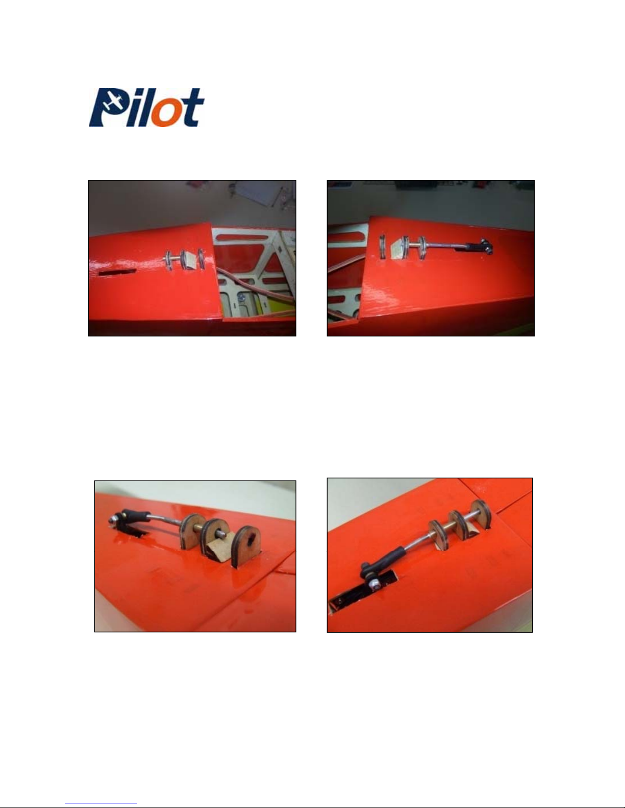
6-) Bond a small piece of
triangular wood stock in front
of one F51, over the removed
covering.
7-) Usi
ng 30 minute epoxy, bond the
servo tray inside the top section, in
line with the fuselage slot, allowing
the servo arm to protrude outside of
the fuselage.
-Closed position--Open position-
-Pilot Trainer- 22
Page 23
Note f
rom
Pilot RC
:
-Included are Laser-Cut plywood parts. These parts
are provided to allow you to repair your Trainer in
case of a mishap.
Initial travel deflections.
-If you need additional parts, please contact Pilot RC
directly.
NOTE: These dimensions are for your first initial
flights. Adjustments can be made to suit your
flying style:
-Ailerons: ¾’’ or 20mm (Up/Down)
-Flaps: 1 ½’’ or 40mm (Down)
-Elevator: 5/8’’ or 32mm (Up/Down)
-Rudder: 2’’ or 50mm (Left/Right)
Center of Gravity:
-5 3/4’’ or 146mm behind the leading edge of
the wing.
-Pilot Trainer- 23
 Loading...