


Predator Sport Jet 126”
USER MANUAL
WINGSPAN:2905mm
LENGTH:3200mm

Introduction
Warrant
● All Pilot-RC products are guaranteed against defects for 30 days of receiving your
airplane. This warranty is limited to construction or production defects in both material and
workmanship , it does not cover any component parts damaged through use or
modification .
● The manufacture cannot supervise the assembly, operation or maintenance, and is not
responsible for radio malfunctions. Please ensure your radio system is in good condition.
We are not responsible for any accident or damage while using this product. It is
impossible to determine for certain whether crash damage was the result of improper
installation of our products, a radio system failure, or pilot error. Model airplane owners use
our products at their own risk.
● Thank you for purchasing our Predator Sport Jet plane. we strive to achieve a good
quality quick build ARF aircraft .
It requires the least amount of assembly of any ARF kit to obtain the maximum
performance.
● Both the design and manufacturing have been undertaken to the highest standards,
using best quality hardware, covering, wood & glue during factory construction stage.
● By optimal weight and balance along with reliable construction, you will find this plane
ideal for flying.
We hope that every effort and service we offer will, in turn, give you confidence using
PILOT Models.
● Have a wonderful time flying your aircraft in a suitable safe space!
●
Pilot
-
RC will not be liable for any costs, unless agreed and proved beyond doubt the
failure was due to faulty materials or fabrication. Any agreed cost will not exceed the cost
of the airframe and not include engine, radio equipment or third party claims.
● Should you wish to return a product or receive replacement parts, all shipping cost must
be paid by the customer.
Attention
● 1. Do not regard this plane as a toy!
● 2. To ensure safety, please read the instruction manual thoroughly before assembly.
● 3. Building and operating an RC Plane of this nature
requires previous experience and competence to an experienced level. This plane is not for
a beginner!
● 4. If you are in doubt have an experienced pilot at hand. Diligent practicing and correct
guidance is essential, accidents can cause bodily harm and property damage.
● 5. Seek assistance from an experienced person or airplane model clubs in assembly,
operation and maintenance to ensure successful training.
● 6. Fly only in a registered RC model club airfield that is approved by your local
Academy of Model Aeronautics (AMA).
● Pilot-RC has the right to revise the plane, the instructions and the limited warranty
without notice. If you have any problems and questions please contact Pilot –RC:
Email: pilot-rc@139.com , info@pilot-rc.com
Phone:+86 760 88781293
FAX: +86 760 88780293
Address: No.34, Chengnan Er Road , Zhongshan city, 528400, Guangdong Province, China

Install kit contents
Install kit contents:
(Some contents like fuel tank etc… has already installed in fuselage)
Aluminum tube
Accessories pack
:

Accessories pack includes
:
Socket head cap screws
Counterstunk cross screws
Cross round head with medium screws
Tapping screws
Hexagon screw in metric system(SHCS)
Battery bandage
Servo aluminum angle
Metric Allen Wrench
Push rot wrench
Wring clamp
Install kit contents
Crowbar
Push rot
Oil nipple suit
Extension cord (Include 4 in 1 and 3 in 1 extension cord)
(Some of accessories like screw/cord ect… isn’t in this accessories pack)
OTHER ACCESSORIES NEEDED TO COMPLETE:
Epoxy Adhesives
Cyanocrylate adhesives
X-Acto and Saw knives
Sandpaper
Thread lock
Aircraft stand or support
Install kit contents
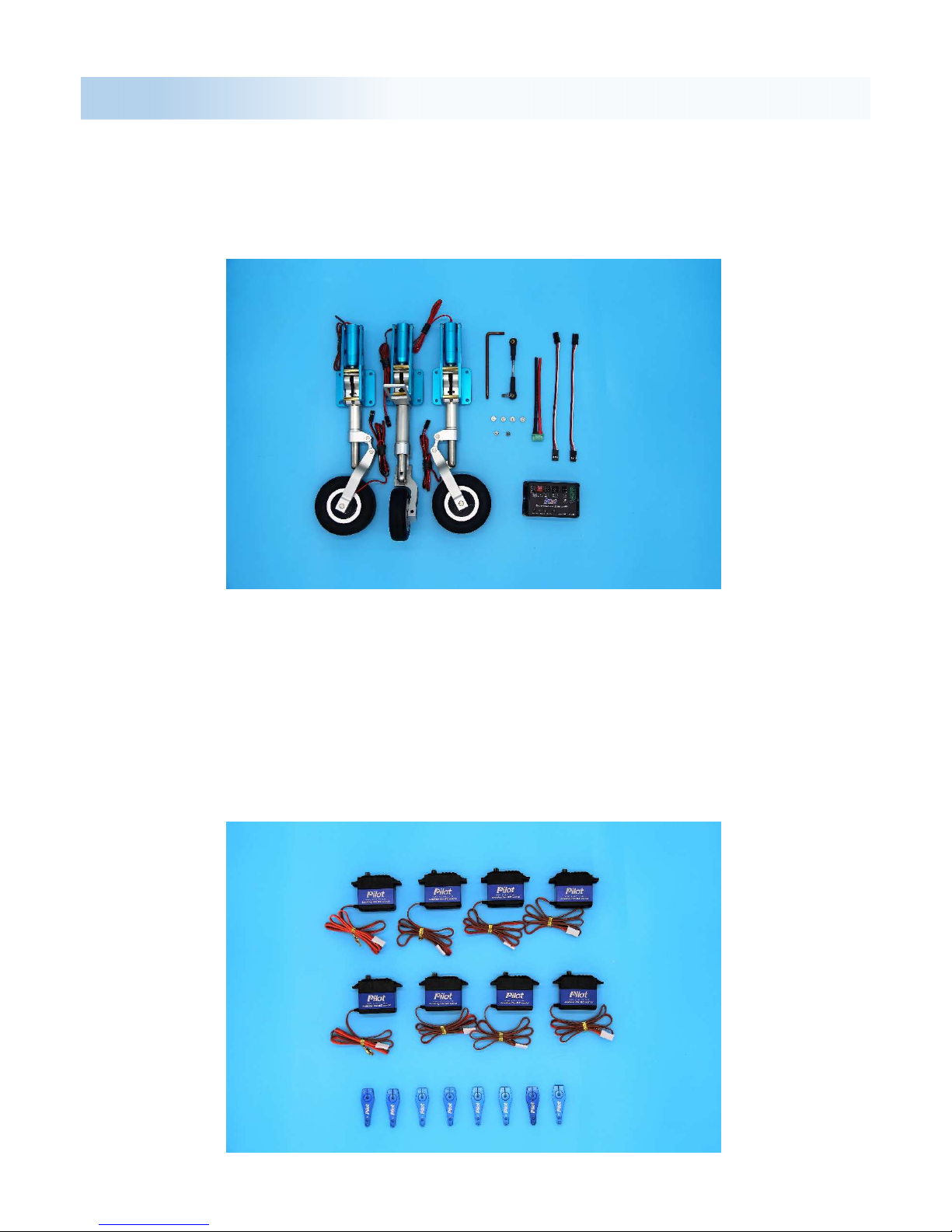
Landing gear module(optional):
Landing gear
Pilot landing gear controller
Servo module(
optional
):
Servo:
PY20AH
Servo arm:
Pilot Futaba aluminum alloy 1.2”
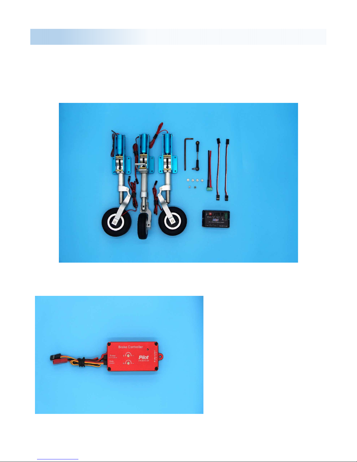
Landing gear assembly
Landing gear assembly:
Retract Landing Gear Installation, Predator Jet come with electriclanding gear and brakes.
We suggested use PilotRC
Brake controller for your
Predator, it can provide
independent brake voltage,
more powerful and reliable.
Note: The brake controller
support power is 7.4V-25.2,
we suggest use 11.1V for
support power.
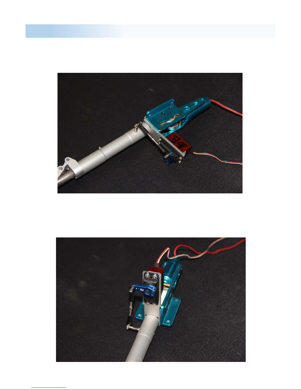
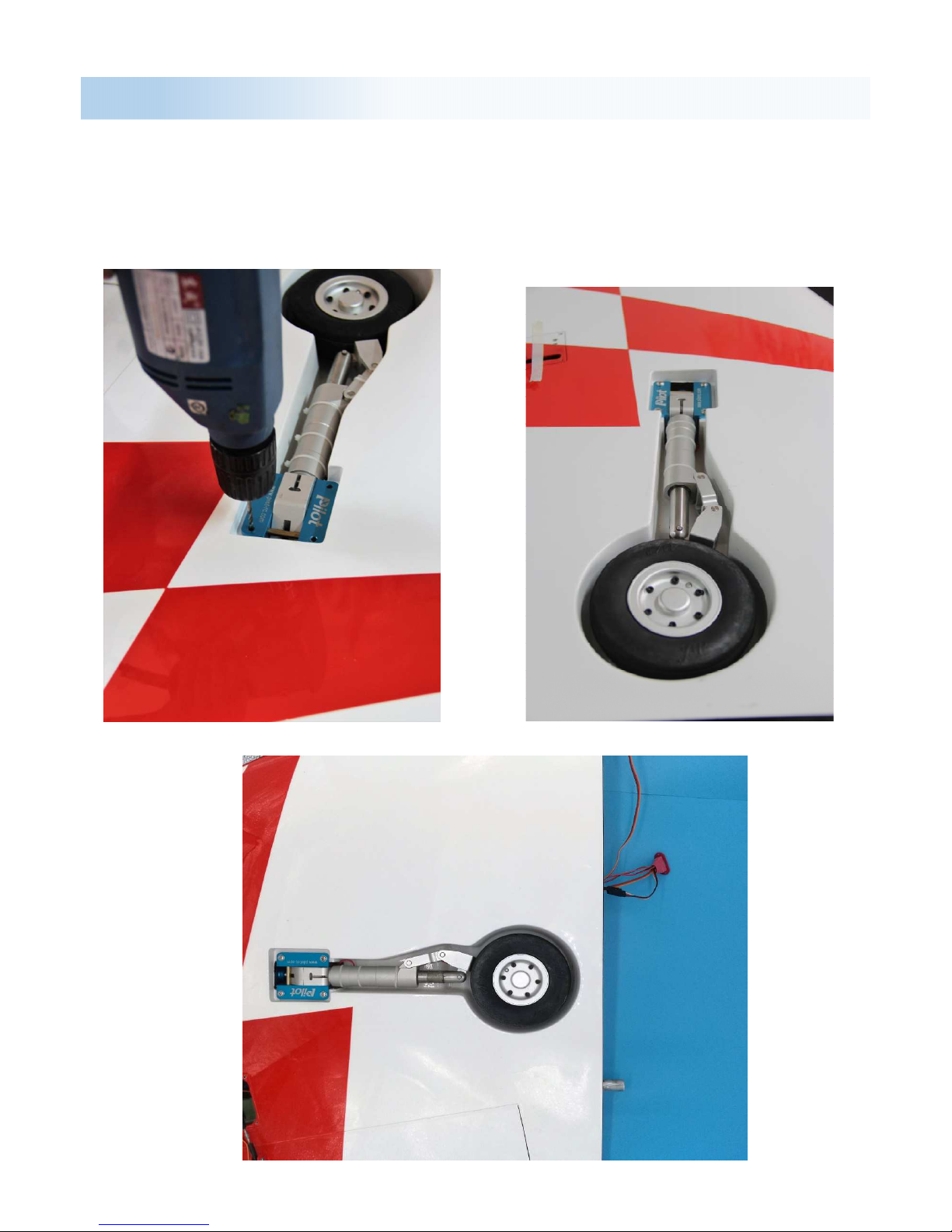
Landing gear assembly - nose
1: Install the servo to the nose landing gear.
2: Install the servo arm and the push rod. Adjust it to make sure the plane can go
straight approx. You still can adjust by radio after install it.

Landing gear assembly - nose
3: Place the nose gear to the mounting and adjust it to the correct position, then
mark the 4 mounting screws hole.
4: Before you drilling the mounting screws hole , please make sure there is nothing
to get stuck when it open and close.
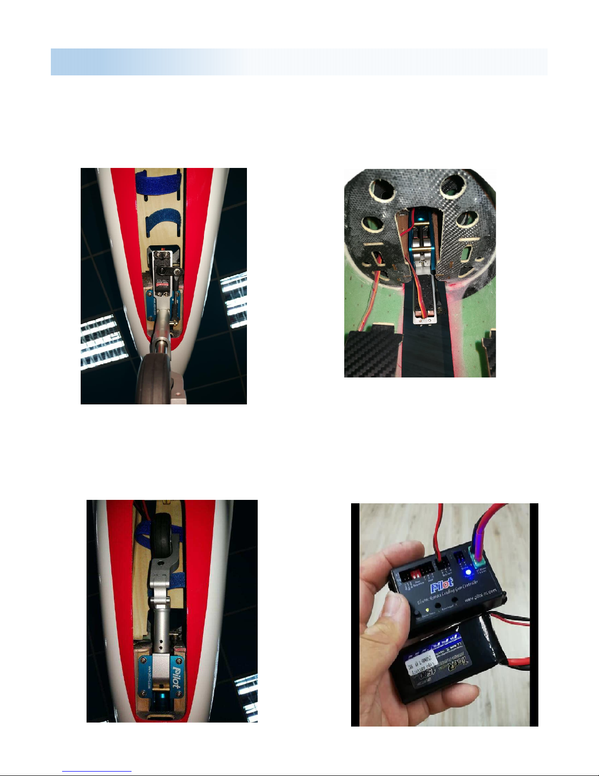
Landing gear assembly - nose
6: Carefully arrange the nose
gear retract wire lead and the
steering wire as well ...
5: This is how it looks like after
installation.
7: Install the nose retract gear to
the fuselage.
8: You can use the gear control
box to operate the landing gear
open or close without your radio
TX.

Landing gear assembly - main
Recommend to use this 4 in 1 MPX style connector from Pilot-RC.
1.Connect all servo / landing gear / brakes wire.
2.The multi connector 4 in 1 out from the opening hole…
3.Double check the positioning of
your gear before drilling any holes.
Make sure that the gear movement
is free of any obstacles.
Landing gear assembly - main
4.Remove the gear and carefully drill
the holes to accept your chosen
screws. We recommend the use of
bolts and blind nuts, however wood
screws can also be used as a “failure
point” in case of a hard landing.

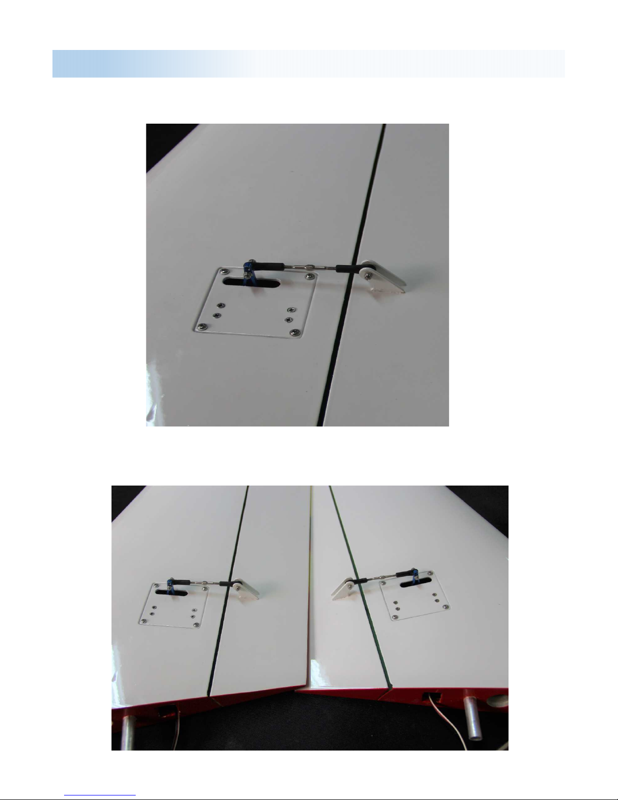
Wing Servo/Flaps Assembly
The control horns are pre-installed at the
factory, ready for use.
1.Screw the servo to the included
aluminium L shaped brackets, then
install the servo arm on to the servo,
making sure that this is centred
2.Place the servo over the servo plate
3.Drill
out the four holes in the plate, then
making sure that the arm moves freely
within the provided slot, and mark out
the placement of the four screw holes
3.Drill
out the four holes in the plate, then
securely screw the servo to the inside of
the plate using the metal screws
provided

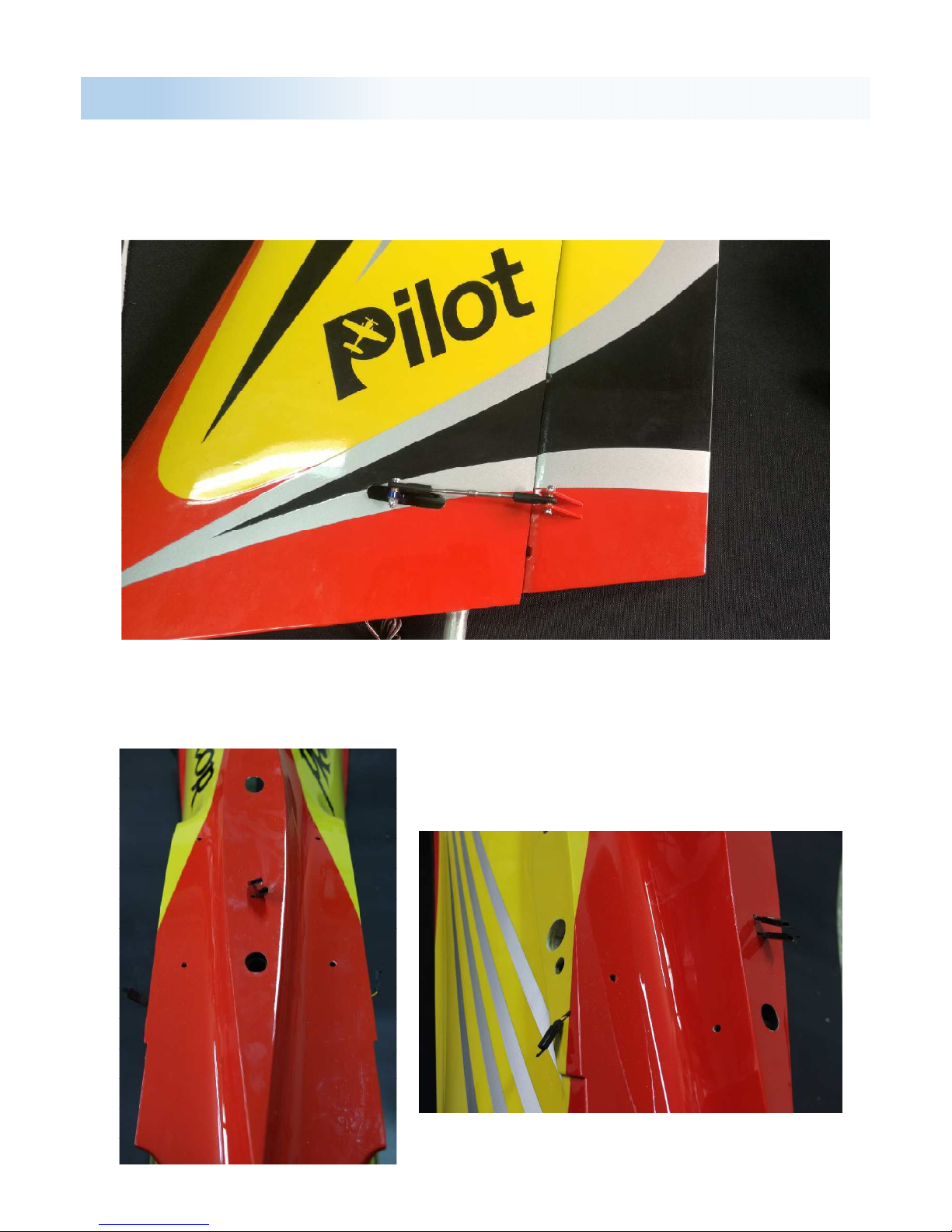
Wing Servo/Flaps Assembly
4.Attach the included pushrods and ball links between the servo arm and the control
horn.
5.Route the servo wire through the inside of the wing toward the fuselage, before
securely screwing the servo plate to the wing with four wood screws

Wing Servo/Flaps Assembly
Aileron servo / Flaps servo / Gear installed
6.Use a thin ply as a back plate and
installed the 4 in 1 connector , use 5
min epoxy to glue it from inside of the
fuselage.
7.Just one connector for
aileron/flaps/landing gear/brakes.
One side of the connector can be
screwed to the fuselage, while the
other is left inside the wing, loose,
for easy connections.
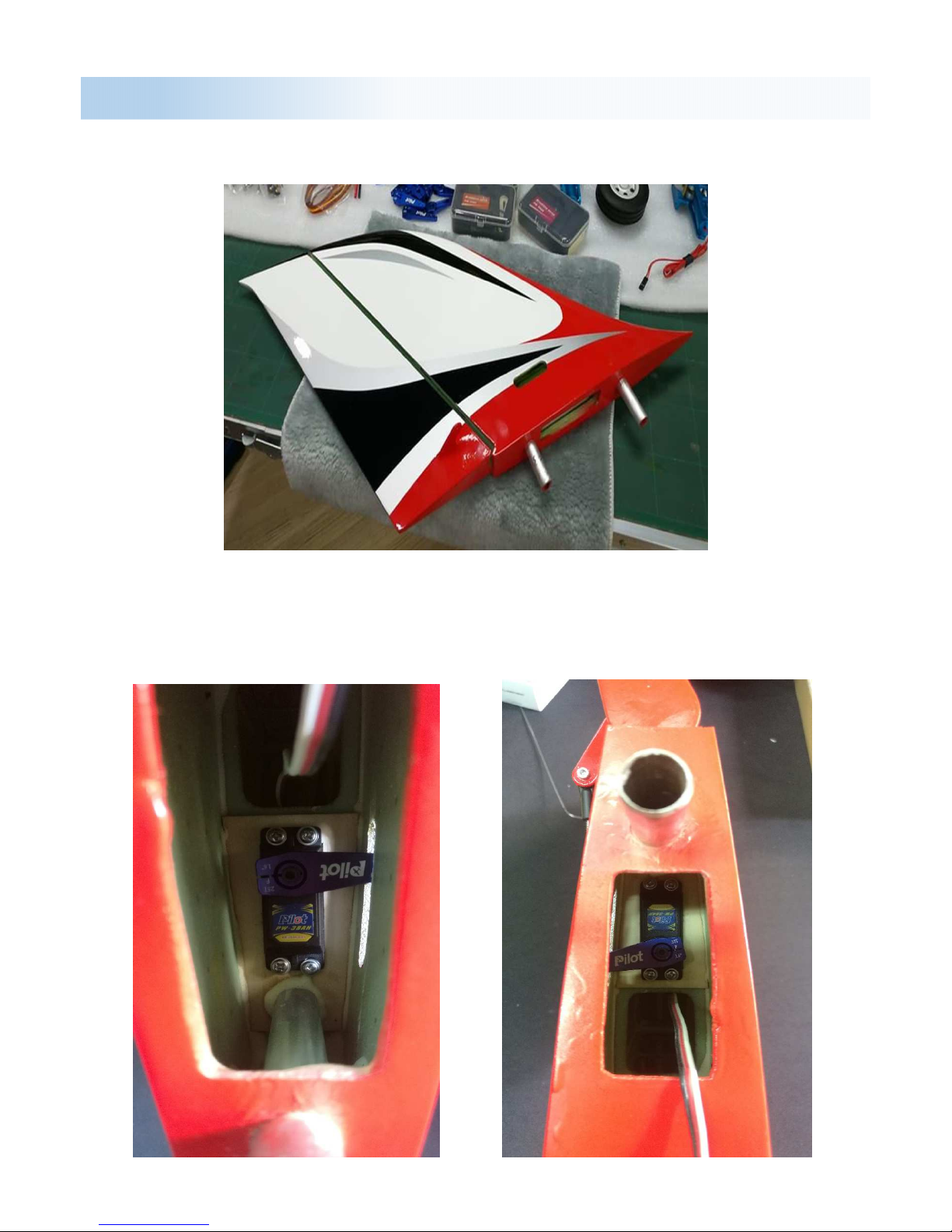
Elevator/ Rudder Servo Assembly
Rudder servo assembly
1.Insert the servo into the rudder, in its allocated slot, with the servo shaft
closest to the rudder.
2.Screw the servo in place, and then install the servo arm on to the servo, making
sure that this is centraed. Attach the included pushrods and ball links between the
servo arm and the control horn.
Elevator/ Rudder Servo Assembly
The rudder extension wire connector.

Elevator/ Rudder Servo Assembly
Elevator servo assembly
1.Take out the elevator plating from the wing and use the supply L-shape aluminium
braket to install the servo
2.Attach the included pushrods and ball links between the servo arm and the control horn
Elevator/ Rudder Servo Assembly
3.Rudder servo and servo arm installed

Elevator/ Rudder Assembly
To assemble the rudder, insert the aluminum tube
Next connect all the servo wire and insert the elevator to the mounting hole
Fasten all of the screws, and make sure they are tighted enough.
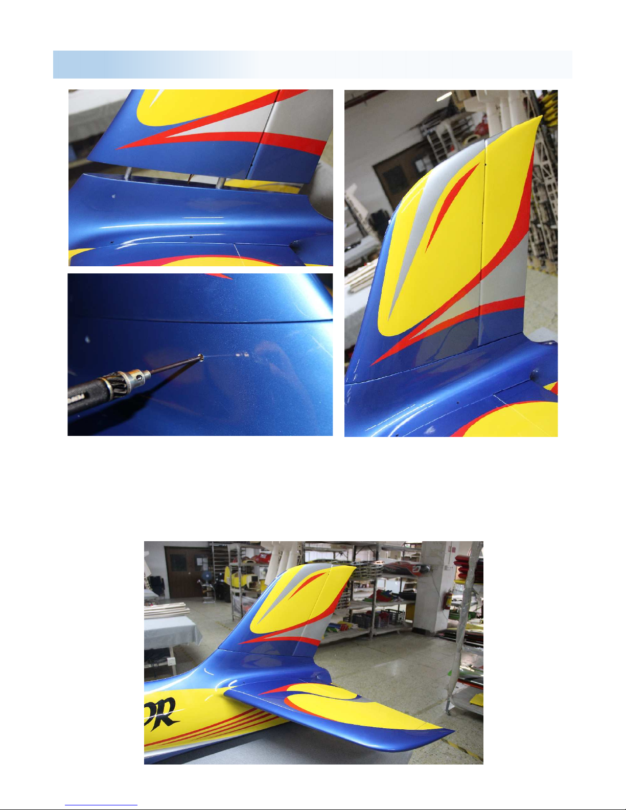
Elevator/ Rudder Assembly
Connect all the servo wire and insert the rudder tube into the
mounting hole on the fuselage.
Fasten all of the screws, and make sure they are tighted enough.
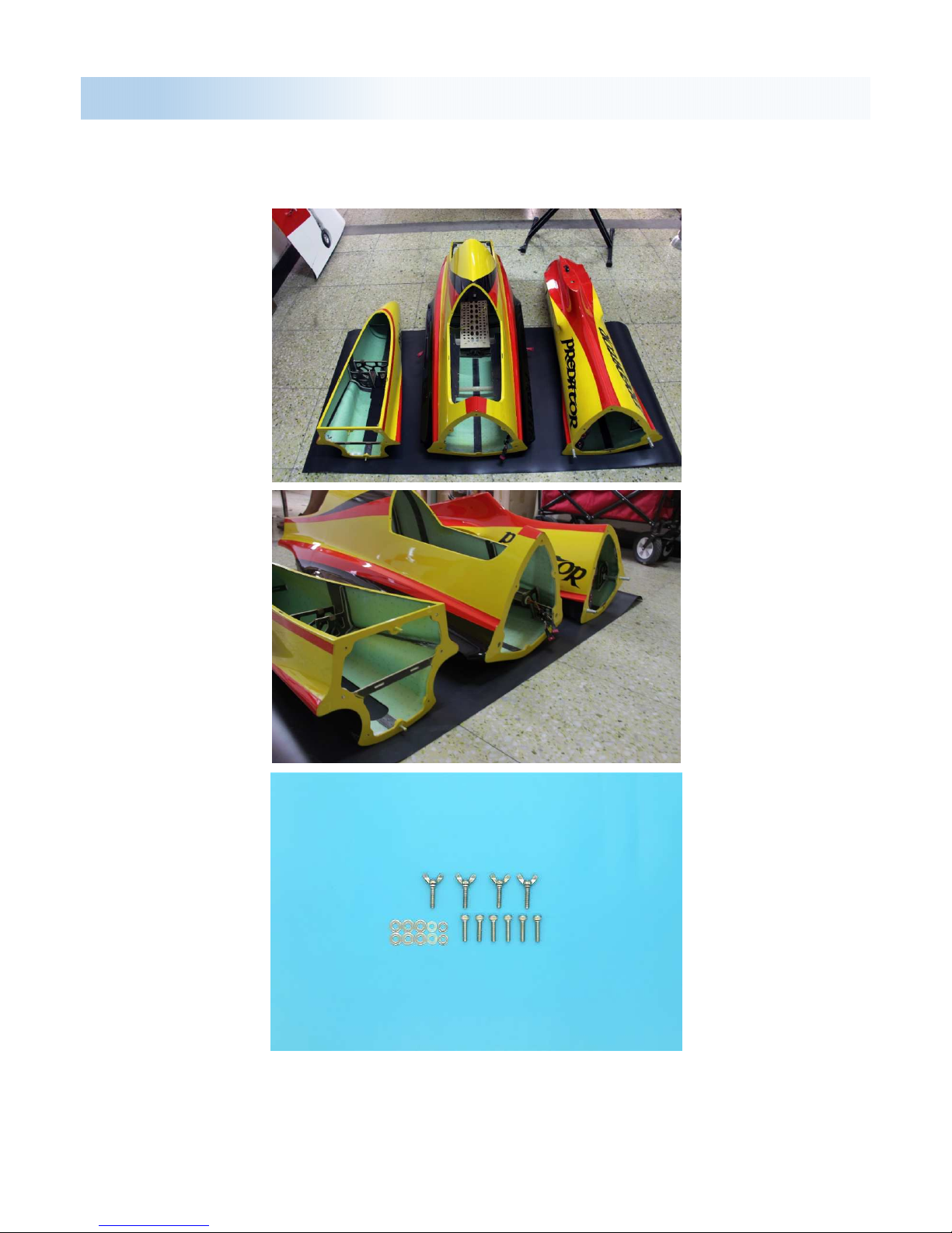
Fuselage Assembly
The 126” Predator’s fuselage divided three pieces. Rear section easily
removable for transport
Fuselage divided three parts:
Front part (For front landing gear, electronic device)
Middle part(For tank, engine, wings)
Behind part(For exhaust pipe, rudder, elevator)

Fuselage Assembly
Front – Middle part
1.First, put the front fuselage and middle fuselage on table or support
shelf. And make sure front-middle part can connect through the limit hole.
2.When connected, use the head screws to fasten all of it. and make sure
all of screws are tight.

Fuselage Assembly
1.When you finish the front-middle part. Then connect the middle-behind
part like before.
Middle - Behind part
2.Use the butterfly screws to fasten all of it, and make sure all of screws
are keep tight.
Need
fasten the
fuselage
connect
pipe.
Circuit Arrangement
Because the Predator fuselage divide three part. and each part have
many electric parts need assemble, so there is many circuit…… So for
easy arrange the circuit, these pictures showed how the circuit arrange in
the fuselage.
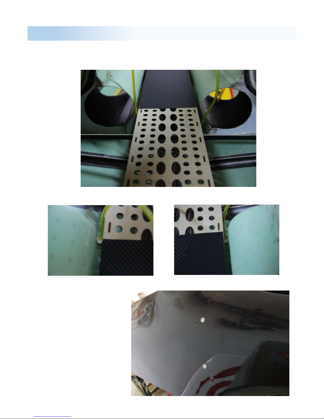
For circuit arrange easily, we set the circuit arrangement tube in each
fuselage, it’s under the mounting plate or at fuselage’s left/right side.

Circuit Arrangement
The front part circuit arrangement(electric parts ect……)

Circuit Arrangement
The middle part circuit arrangement(wings, gear)

Circuit Arrangement
The behind part 3 in 1 connector circuit arrangement (rudder, elevator)
All these pictures are suggestion, you can arrange circuit by your way.
And for easy arrange these circuit, you may need some tools like
tweezers, stay wire ect…
3 in 1
connector
To Elevator
To Rudder
To Elevator

Electric parts Arrangement
The electric
parts arrange,
we divided it
for two parts:
front part is oil
filler(smoke
oil filler)hole
and
MERCURY
display, switch.
behind part is
MERCURY,
landing gear
controller, oil
pump,
receiver, flying
control system.
ect……

Engine Arrangement
For install the engine, we suggest install the exhaust nozzle first, when
the nozzle setting done, we can locate the engine’s setting position, and
install it.
Side support
arrange
position.
Need 4
tapping
screws to
fasten it.
Here use M3
claw screws
to fastening it.

Engine Arrangement
When arrange the engine, must make sure the screws are tight with
engine and mounting plate

Tank Arrangement
The 126” predator use PilotRC 3 in 1 Kevlar tank. It’s included
7800ml fuel tank, 2400ml smoke tank and 500ml UAT
2400ml smoke tank
7800ml fuel tank
500ml
UAT

Tank Arrangement
To atmosphere
Fuel vent
Smoke oil in Smoke oil out(to somke pump)
Tank linking hole connecting diagram.
UAT to Pump
Fuel in
UAT to oil tank
UAT to oil tank
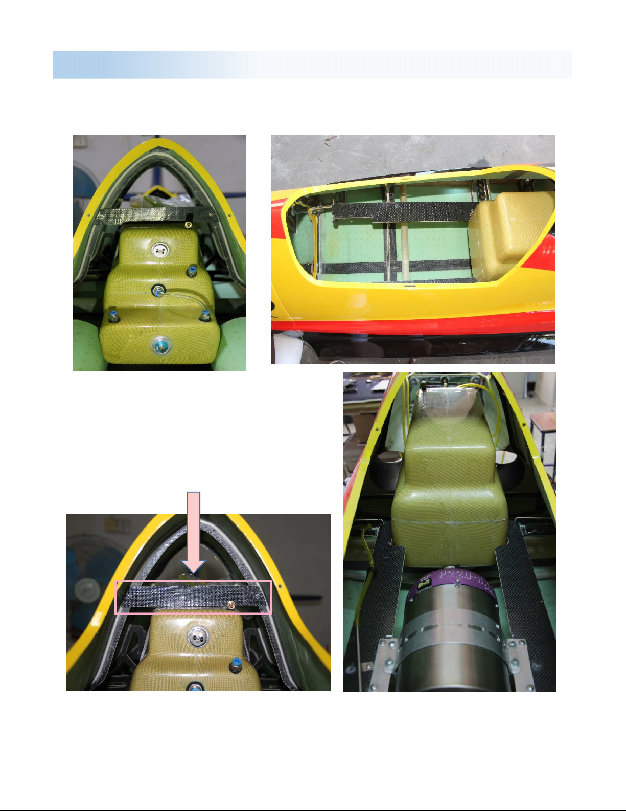
Tank Arrangement
To make sure the tank arrange position, put the tank in to the slot,
and make sure the tank is in the current position.
When tank in position, use double sticky tape to stick the tank on the fuselage,
and use the velcro strap to hold the tank, make sure the tank is tight with
mounting plate.
This tank limits plate you need install
by yourself, use glue to glue it on the
fuselage, and use bolt to securing it.
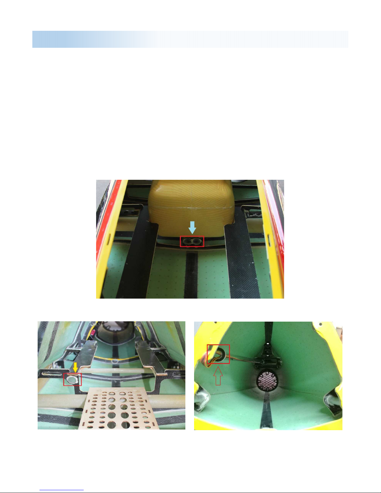
Tank Arrangement
After the tank arrangement, to set the fuel vent installing
hole in the fuselage, it’s under the mounting plate, behind
the air inter.
Fuel vent Left Fuel vent Right
Fuel vent installing hole
settled done, it’s under
the fuselage.
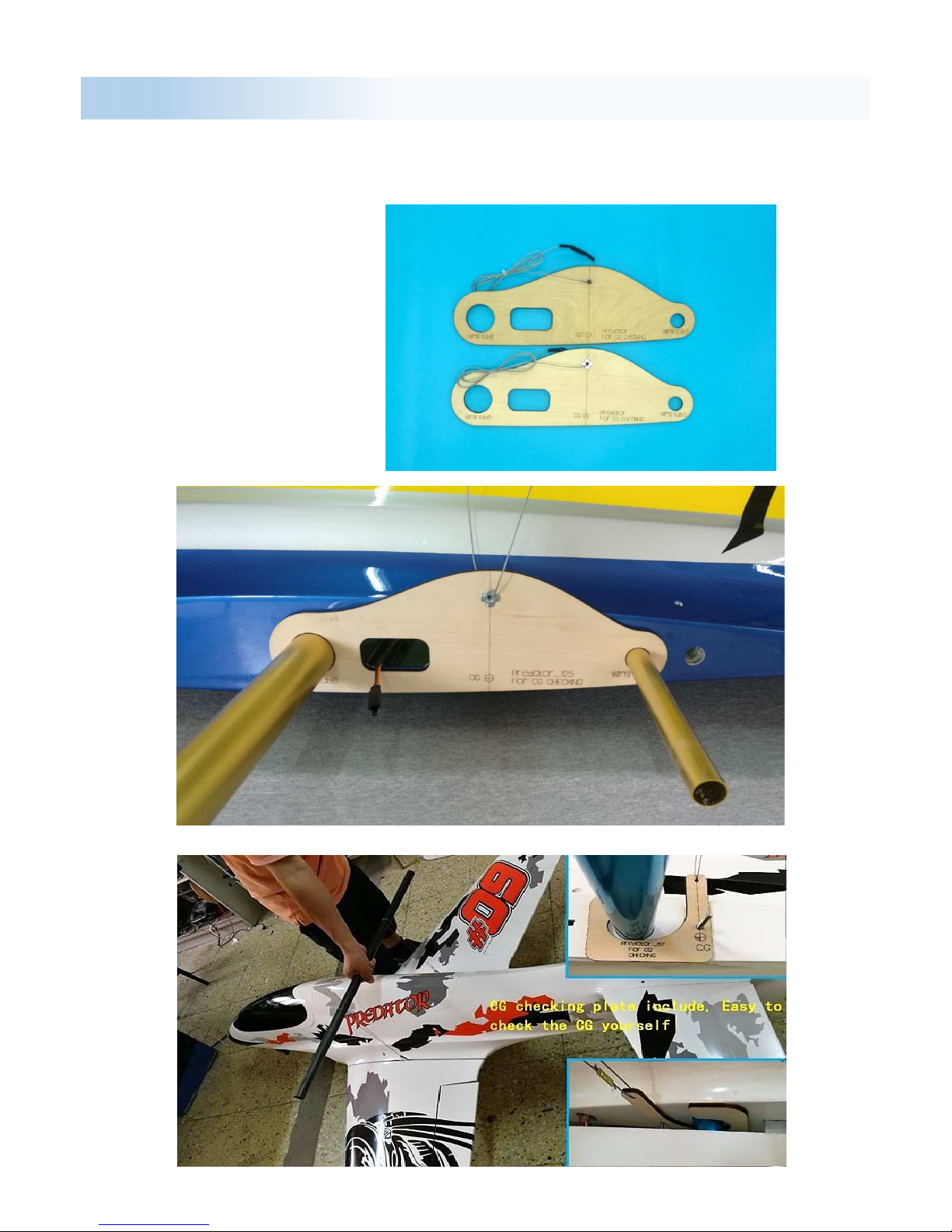
CG Checking
The Predator have CG measuring tools for checking CG, you can
checking CG by this tool.
Please check the CG
without empty oil tank.
Click here for the video:
https://www.facebook.com
/khaitang.wong/videos/187
5569852454736/
Aileron
:
36mm
Rudder
:
432mm
Elevator:33 mm
Flaps
:
55mm for take off
120mm for landing
CG:The CG is 430mm from the front leading edge on the root of the
wing.
Flying Setting

■ Make sure you have the right model programmed into your transmitter
■ Check the direction of each surface not and also right before you take off .
■ Remember nothing wrong on the ground ever improves in the air
■ Check the air plane with the engine running and do a range check with
■ your body between you and the plane at least 150 feet.
■ Check your battery voltage after each flight, in case one servo is draining your
battery
■ Recheck all screws ,horns and linkages for slop after your maiden fight and
check for damage if you made a bad landing you first time
■ Have an experienced pilot fly it for you the first time if you have any doubts in
your mind about the maiden flight
■ Take a break after you first flight and let the adrenaline burned off by bragging to
your fellow members how good it flies
■ Fly low and at a medium speed on your first few flight
■ Listen to your engine run and have an observer with you to remember what you
talked about during the flight or if you get into trouble . Always balance your props,
Flight Preparation
vibration is a killer.
■ Remember nose heavy airplanes fly all the time, tail heavy airplanes fly only
once. Be on the CG!
■ Flying two mistakes: high in the beginning and not close to people, planes or
runways. Being a center of the runway hog does not endear you to many modelers.
Double Check
Double check that all screws are installed, all components tightly secured, batteries
and or fuel tank are full, all surfaces are working in the correct directions, balance is
correct and range test passed before performing your maiden flight.
WE WISH YOU A SUCCESSFUL MAIDEN AND MANY HAPPY FLIGHTS WITH YOUR NEW
MODEL
Tony Tan, Pilot-RC

Address: No.34, Chengnan Er Road, Zhongshan city, 528455,
Guangdong Province, China
Web: www.pilot-rc.com
Email: pilot-rc@139.com, info@pilot-rc.com
Tel: +86-760-88781293 FAX: +86-760-88780293
Zhongshan Pilot Model Aircraft Product Ltd
 Loading...