

Page 1
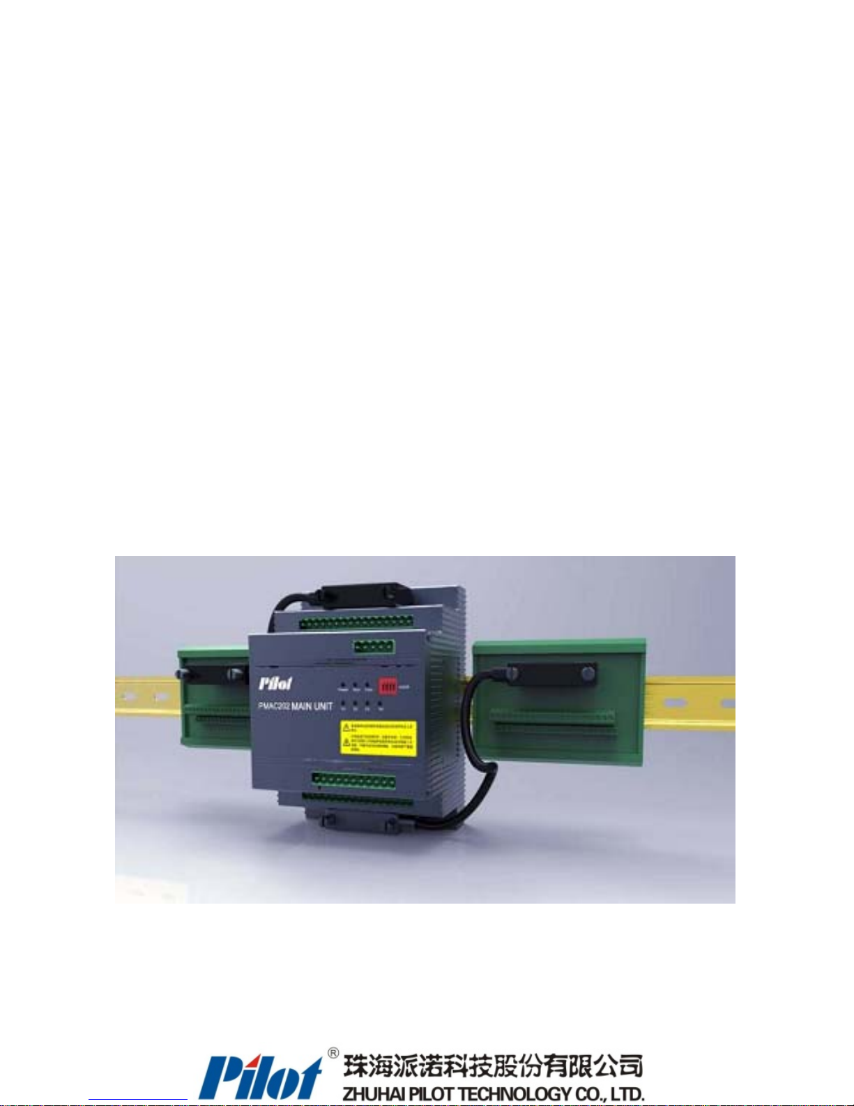
PMAC202 Branch Circuit Power Meter
User Manual
V
1.0
Installation & Operation Manual
Page 2
Danger and Warning!
This device can be installed only by professionals.
The manufacturer shall not be responsible for any accident caused by failure to comply with the instructions in this manual.
Risks of Electric shocks, buring or explosion
z This device can be installed and maintained only by qualified people.
z Before operating the device, isolate the voltage input, power supply and short-circuit the secondary windings of all current transformers.
z Put all mechanical parts, doors, or covers in their original positions before energizing the device.
z Always supply the device with the correct working voltage during its operation.
Failure to take these preventive measures would cause damage to the equipment or injuries to people
Page 3

Contents
Contents
1. PRODUCT INTRODUCTION ................................................................................................................................... 2
1.1 Overview ............................................................................... 2
1.2 Product Features: ....................................................................... 2
1.3 HMI Human-Computer Interface ........................................................... 2
1.4 Product Composition ..................................................................... 3
2. PRODUCT PERFORMANCE AND FUNCTIONALITY ....................................................................................... 5
2.1 Product Model .......................................................................... 5
2.2 Product Function ........................................................................ 6
2.3 Technical Specification ................................................................... 7
2.4 EMC Properties ......................................................................... 8
2.5 Operating Environment ................................................................... 8
3. INSTALLATION ......................................................................................................................................................... 9
3.1 Main module Index ...................................................................... 9
3.1.1 Main Module Installation detail drawing ................................................ 10
3.1.2 Main Module Dismantle detail drawing ................................................. 10
3.2 Status Module Index .................................................................... 11
3.3 CT Module Installation Index ............................................................. 12
3.4 Outgoing Single Installation CT Index ..................................................... 12
3.4.1 CT Switching Module Index .......................................................... 12
3.4.2 50A Single CT Index ................................................................ 13
3.4.3 100A Single CT Index ............................................................... 13
3.4.4 200A Single CT Index ............................................................... 14
3.5 Incoming Line Leakage Current Transformer Index .......................................... 14
3.6 HMI Module Index ...................................................................... 15
4. CONNECTION WIRING ..............................................................................................................................
........... 16
4.1 Main Module Terminals .................................................................. 16
4.2 Switching Value Module Terminals ........................................................ 17
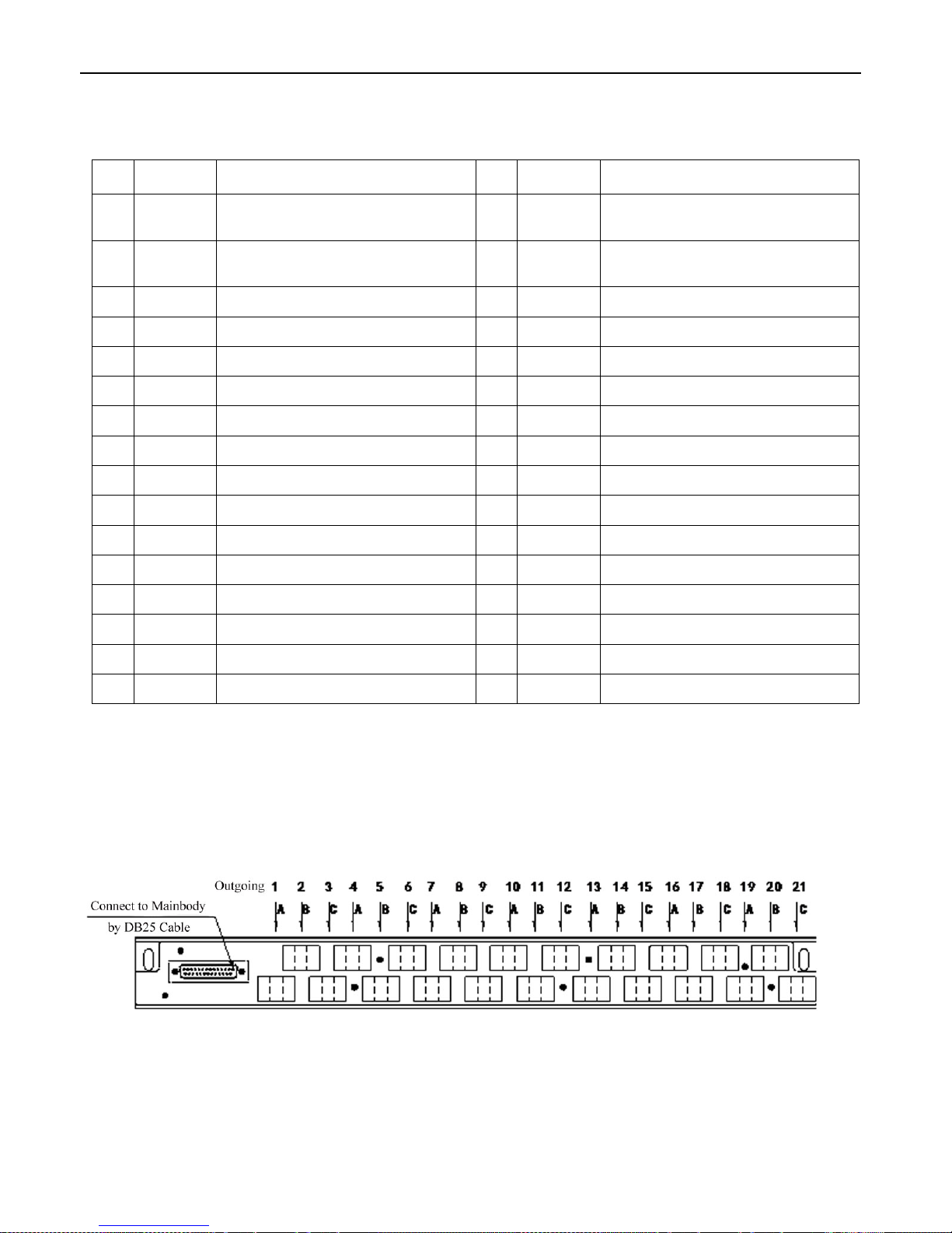
4.3 CT Module Terminals ................................................................... 17
4.4 HMI Power Connection .................................................................. 18
4.5 Incoming Line Connection Wiring ......................................................... 19
4.6 Outgoing Line Connection Wiring ......................................................... 20
4.7 One Way Incoming Line System Connection Wiring ......................................... 21
4.8 Two Way Incoming Line System Connection Wiring ......................................... 22
4.9 One Main & One Backup Incoming Line System Connection Wiring ........................... 23
4.10 Multi Main Module Address Setting ...................................................... 24
Page 4

Contents
5. DISPLAY AND OPERATION ................................................................................................................................. 25
5.1 System Configuration ................................................................... 25
5.1.1 One way Incoming Line Configuration ................................................. 25
5.1.2 Two way Incoming Line Configuration ................................................. 25
5.1.3 One Main & One Backup Incoming Line Configuration ................................... 26
5.1.4 Clear Energy ....................................................................... 26
5.1.5 Clear Maxim Value .................................................................. 27
5.1.6 Time Synchronization ............................................................... 27
5.1.7 Function Configuration .............................................................. 2 8
5.1.8 Setting ............................................................................ 28
5.1.9 Password Input ..................................................................... 28
5.1.10 Password Modification ............................................................. 28
5.2 Data Display ........................................................................... 29
5.2.1 Real Time Data Display .............................................................. 29
5.2.2 Switch status display ................................................................ 29
5.2.3 Alarm display ....................................................................... 29
5.2.4 Communication Status Indicate ....................................................... 29
5.2.5 Key Operation ...................................................................... 30
5.3 Incoming Circuit Data Display ............................................................ 30
5.4 Outgoing Circuit Data Display ............................................................ 30
5.5 Real-time Alarm Record Display .......................................................... 31
5.6 Incoming Circuit Value Programming ...................................................... 32
5.7 Outgoing Circuit Value Programming ...................................................... 33
5.8 History Electrical Degree ................................................................ 35
5.9 CT Setting
............................................................................. 36
5.10 Data Record .......................................................................... 37
6. MAINTENANCE AND TROUBLE SHOOTING .................................................................................................. 38
Page 5

PMAC202 Branch Circuit Power Meter · 2
1. Product Introduction
1.1 Overview
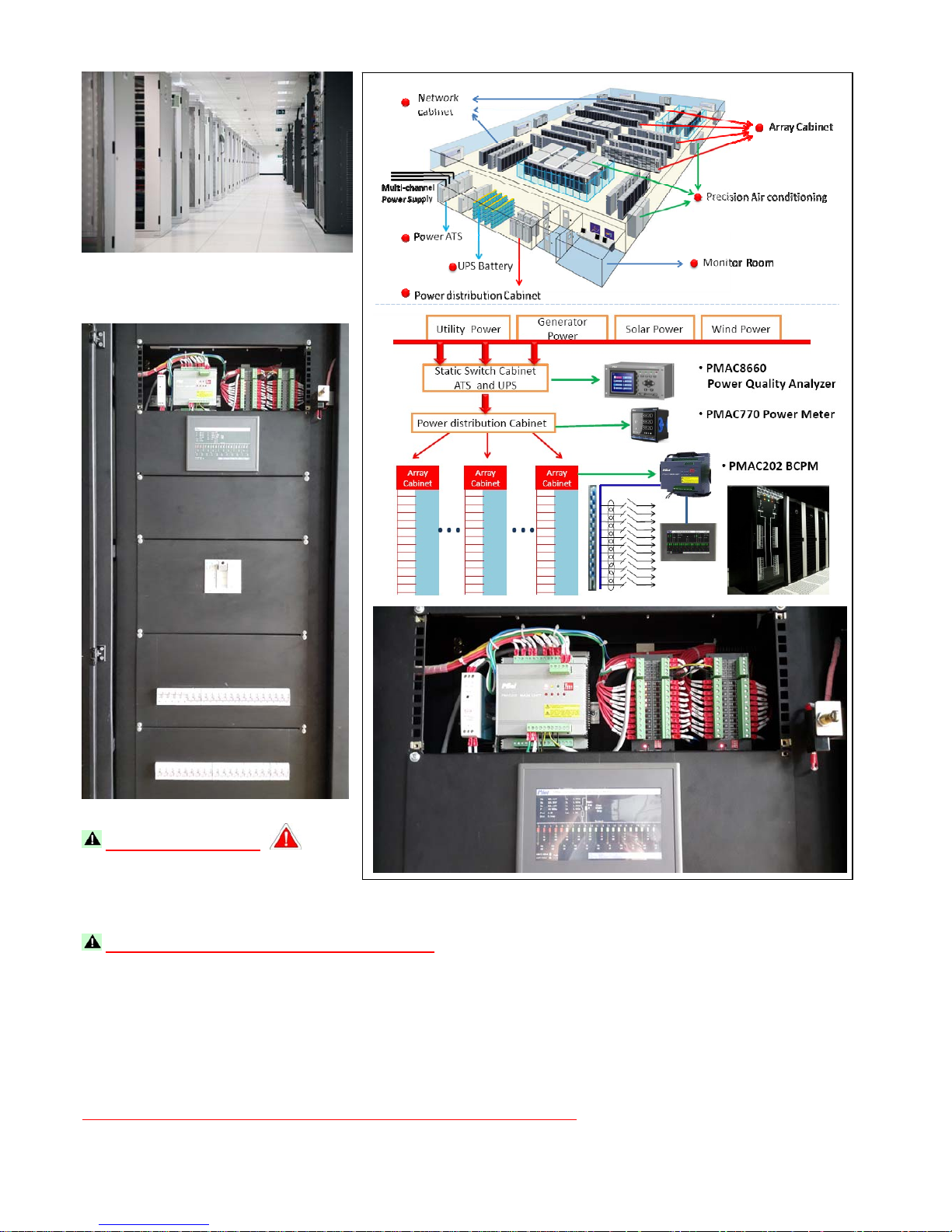
PMAC202 Branch Circuit Power Meter is specially designed for monitoring Power supply distribution cabinet in data center, which
can monitor incoming circuit and outgoing circuit parameters, DI/DO status, fulfill monitoring for power supply distribution cabinet
and alarming for abnormal voltage and current information. 7 inch HMI with system chart display which can best fulfill visuality and
operability, customer can choose 21
st
– 168st (Unit: 21st) outgoing circuit by load quantity. This PMAC202 also provide extra
communication port which can easily connect with other systems.
1.2 Product Features:
1. Metal case, efficiently electromagnetic interference shield
2. Module design, separate Main-body module, CT module, Digital Input module, can fulfill different
technical requirement
3. 7 Inch HMI human-computer interface, good visuality and operability
4. No extra secondary contact, each DI/DO switch has separate status indicate light
5. Can measuring incoming circuit Null Line current
6. Can measuring incoming circuit Leakage current
7. Can measuring Null earth voltage
8. Can measuring outside temperature
9. Relay alarm function, can record more than 2000 pieces alarming information
10. Measuring the KWH on 2 loop incoming and each outgoing circuit, fulfill energy management
requirement
11. Measuring harmonic of voltage and current, monitoring power supply quality
12. Current Transformer accuracy is 0.2%, make sure the measuring accuracy
13. Modbus-RTU protocol, Rs485 communication
1.3 HMI Human-Computer Interface
PMAC202 branch circuit power meter with 7 inch touch screen human-computer interface, system chart
display, with best visuality and operability.
Page 6
PMAC202 Branch Circuit Power Meter · 3
1.4 Product Composition
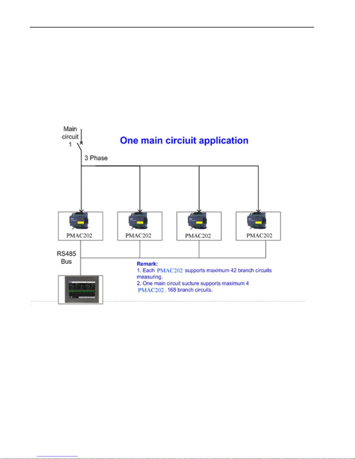
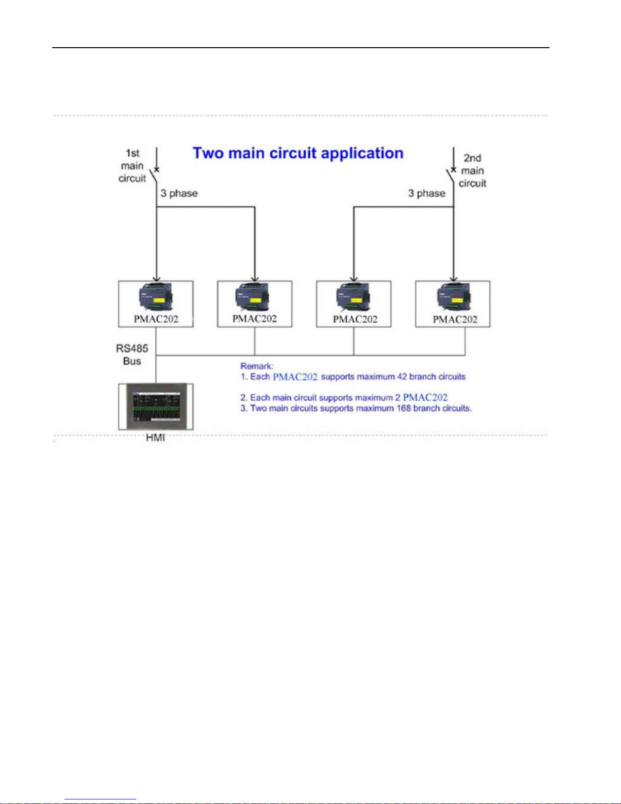
PMAC202 Branch Circuit Power Meter with module design which including Main-body module,
Digital Input module, HMI module, CT module. According to different application to choose different
configuration, following are two main typical application for reference:
One Way Incoming Line:
Page 7
PMAC202 Branch Circuit Power Meter · 4
Two Way Incoming Line:
Page 8

PMAC202 Branch Circuit Power Meter · 5
2. Product Performance and functionality
2.1 Product Model
Name
PMAC202 Branch Circuit Power Meter
Model
PMAC202-□-□-□-□-□
① ② ③ ④⑤
Alternative①
A or B
A- Basic Model
Main Circuit measuring: 3 phase voltage, current, current unbalance, current demand
per phase, maxim current demand, maxim current, active power (total/each
phase), reactive power (total/each phase), power factor, frequency, active
energy, reactive energy, voltage THD, current THD, neutral current, 4 status
input, 2 relay output
Branch Circuit measuring: current, active power, reactive power, power factor, active
energy, reactive energy, current demand, maxim current demand, maxim
current, current THD
B- Advanced Type
On the base of A Basic model, expanded status input for each branch circuit
Alternative②
21 or 42
21- Monitoring 21 branch circuits
A Type: One 21 loop CT module
B Type: One loop CT module + One 21 loop Status module (Advanced Type)
42- Monitoring 42 branch circuits
A Type: Two 21 loop CT module
B Type: Two loop CT module + Two 21 loop Status module (Advanced Type)
Alternative③
M or S
M1- Branch Circuit 21 loop CT strip, Rated Current: 50A
S1- Branch Circuit separate CT, Rated Current 50A
S2- Branch Circuit separate CT, Rated Current 100A
S3- Branch Circuit separate CT, Rated Current 200A
Alternative④
T、L、TL
T- One loop temperature measuring, PT100 device
L- One leakage current measuring, rated current 1A (primiary)
TL- One loop temperature and One leakage current measuring
A⑤ lternative
W or Y
W- Branch Circuit External Status input Dry connection
Y- Branch Circuit External Status input Wet connection
Page 9

PMAC202 Branch Circuit Power Meter · 6
2.2 Product Function
Function Illustration
Incoming Line
Null Line Current monitoring Monitoring Null Line current of incoming line
Leakage Current monitoring Incoming Line leakage current monitoring, Rated value is 1A (primary)
Temperature monitoring
One loop temperature monitoring, range: 0—120 degree. Measuring Isolation
Transformer temperature
Incoming line Switch status monitoring
4 loop status used to measuring incoming line switch and lighting protection switch.
External Wet connection
Incoming line electrical parameter
measuring
including phase voltage, phase current, phase maxim current, current unbalance, each
phase active power, total active power, total power factor, frequency, total KWH
Incoming line demand measuring
Each phase current demand, maxim current demand, each phase active power
demand, each phase maxim active power demand, total active power demand, maxim
total active power demand
Incoming Line Harmonic measuring Phase voltage, current total harmonic distortion (2-31st harmonic) of incoming line
Incoming overload alarm Over than setting current value will alarm, it is UP limit alarm and Over UP limit alarm
Incoming underload alarm
Less than setting current value will alarm, it is Lower limit alarm and Over Lower limit
alarm
Incoming line Current Unbalance alarm Over than setting unbalance value will alarm, one setting value
Incoming line Over Voltage alarm Over than setting voltage value will alarm, one setting value
Incoming line Under Voltage alarm Less than setting voltage value will alarm, one setting value
Null Line Over Current alarm Over than setting current value will alarm, one setting value
Incoming Line Voltage
default phase Alarm
If there is any phase measuring voltage is 0, and exist another phase voltage higher
than 20V at the same time, the Default phase alarm will work. There is no setting value
for default phase alarm
Leakage current over current alarm Over than setting current value will alarm, one setting value
Temperature alarm Over than setting temperature value will alarm, one setting value
Outgoing Line
Multi-channel outgoing line monitoring Can provide 21st, 42nd loop outgoing line circuit for choosing
Outgoing Line Switch status monitoring Monitoring multi-channel Switch ON/OFF status, No auxiliary contact is also OK
Outgoing Line electrical parameters
measuring
Current, Maxim Current, Active Power, Reactive Power, Power Factor, KWH, Current
THD
Outgoing Line Demand measuring
Current demand, Maxim current demand, Active Power demand, Maxim Active Power
demand
Outgoing Line Overload Alarming Over than setting current value will alarm, it is UP limit alarm and Over UP limit alarm
Outgoing Line Underload alarming
Less than setting current value will alarm, it is Lower limit alarm and Over Lower limit
alarm
Page 10

PMAC202 Branch Circuit Power Meter · 7
Switch status change alarm
Alarm for switch change from OFF to ON, can close by software
Others
HMI 7 Inch touch screen, resolution 800x480
Communication Port RS485 Modbus-RTU Protocol
Relay Output 2 relay as alarm port
Event record function HMI can record more than 2000 pieces alarming events
Setting Function Setting parameters by HMI, such as: CT Ratio, Alarm value
Running Indication Main module and Digital Input module with running indicate light
Switch Status Indication Switching value indicating light
Outgoing phase sequence
configurable
Outgoing phase sequence can be configured by HIM or Communication
kWh Pulse output Active Power pulse output can be configured as Incoming line or Outgoing line
Data Record Record History KWH and Current for Year, Month of Incoming line and Outgoing line
2.3 Technical Specification
Name Illustration
Power Supply DC 24V,Range: 18~30V。
Mean free error time No less than 50000 hours
Life time
10 Year
Rated Voltage
AC 220V phase voltage,Range: 10%~120% Rated Value;
Accuracy: 0.5%
Rated Incoming line
Current
5Aac,Range: 1%~120% Rated Value;Accuracy: 0.5%
Rated Outgoing Current 50Aac,1%~120% Rated Value;Accuracy: 0.5%
Demand Measuring Demand period 15 minutes, slip frequency time 1 minute
Rated Frequency 50Hz,Range: 45~60Hz,±0.01Hz
Power Factor Incoming circuit accuracy: 1%,Outgoing Circuit accuracy: 1%
Active Power and KWH Incoming circuit accuracy: 1%,Outgoing Circuit accuracy: 1%
Leakage Current 1A ac, Range: 10%--120% rated, accuracy: 0.5%
Null-Earth Voltage 5V ac, Range: 10%--200% rated, accuracy: 0.5%
Communication port RS485
Switch Status
Outgoing: Wet contact signal input, 220Vac, 70%--120% rated value or Dry contact input
Incoming: Dry contact input
Relay Capacity AC 250V/5A or DC 30V/5A
Page 11
PMAC202 Branch Circuit Power Meter · 8
2.4 EMC Properties
Items Technical Index Standard
Electrostatic Discharge
Immunity Test
Level 3 IEC61000-4-2
Radiated Immunity Test
Level 3 IEC61000-4-3
Electrical Fast Transient/Burst
Immunity Test
Level 3 IEC61000-4-4
Surge Immunity Test
Level 3 IEC61000-4-5
Power Frequency withstand
voltage
Rated Insulation Voltage≤ 300V,Test Voltage 2000V
Rated Insulation Voltage≤60V,Test Voltage 1000V
GB/T 17215.211-2006
2.5 Operating Environment
Item Parameter
Application Site Indoor
Operating temperature -10 ~55℃℃
Storage temperature -25 ~70℃℃
Humidity 5%~95% RH, non-condensing
IP Grade IP20, HMI (front panel) IP65
Insulation resistance
No less than 100MΩ,IEC62052-11
Page 12
PMAC202 BCPM User Manual · 9
3. Installation
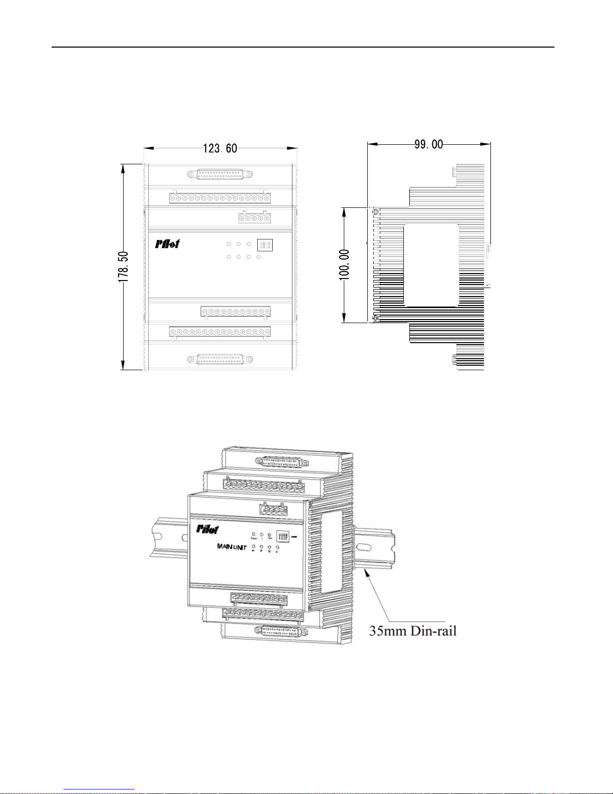
3.1 Main module Index
Power Run Com
S1 S2S3S4
ADDR
MAIN UNIT
Picture 3.1 Main Module Index
Picture 3.2 Main Module Installation
[Note]: Main Module is Din-rail installation
Page 13
PMAC202 BCPM User Manual · 10
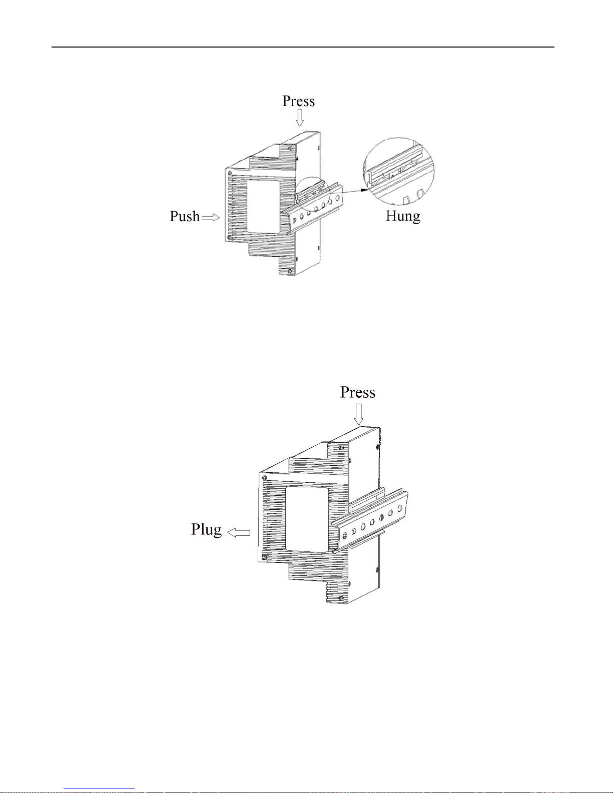
3.1.1 Main Module Installation detail drawing
Picture 3.3 Main Module Installation detail drawing
3.1.2 Main Module Dismantle detail drawing
Picture 3.4 Main Module Dismantle detail drawing
Page 14
PMAC202 BCPM User Manual · 11
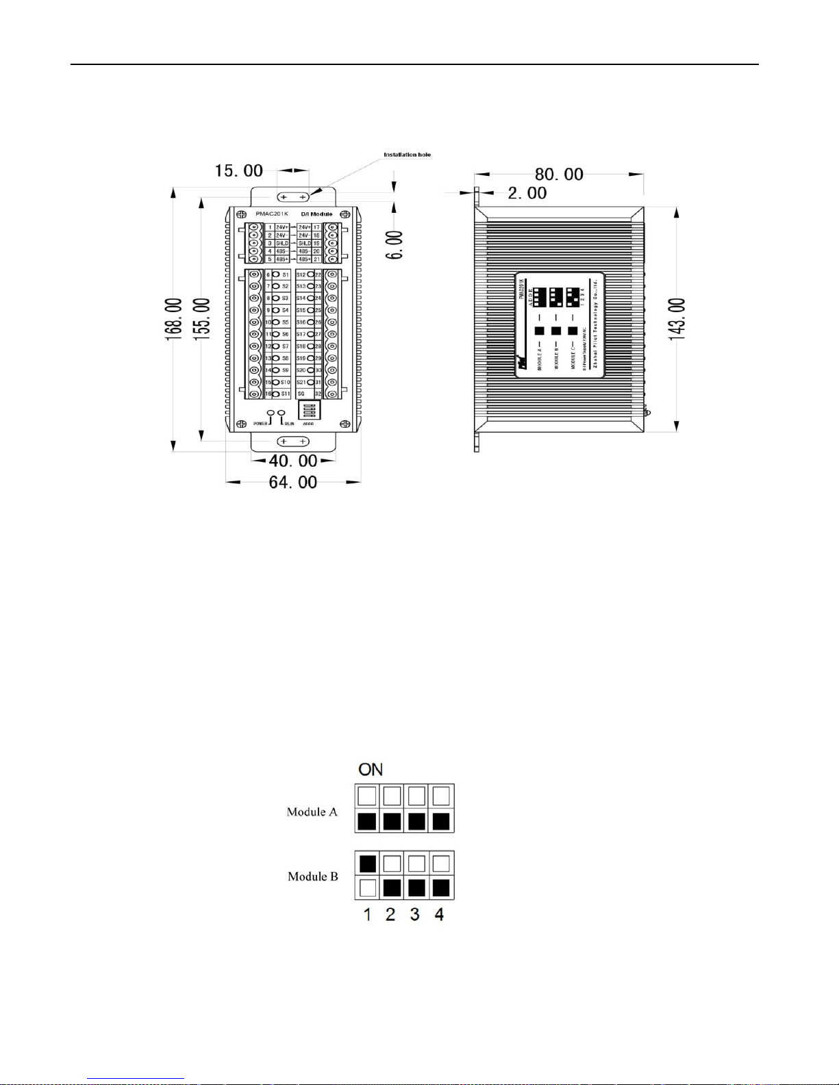
3.2 Status Module Index
Picture 3.5 Status Module Index
Note:
1. Status Module fixed installation
2. Running Indication Light: Flash means normal working and on communication; Light normal ON, means normal
working but no communication
Status Module Address setting
One Main Module can support 2 piece 21 loop Status Module, the address of status module setting by dial
switch, setting dial switch as following
Picture 3.6 Module Address
Page 15
PMAC202 BCPM User Manual · 12
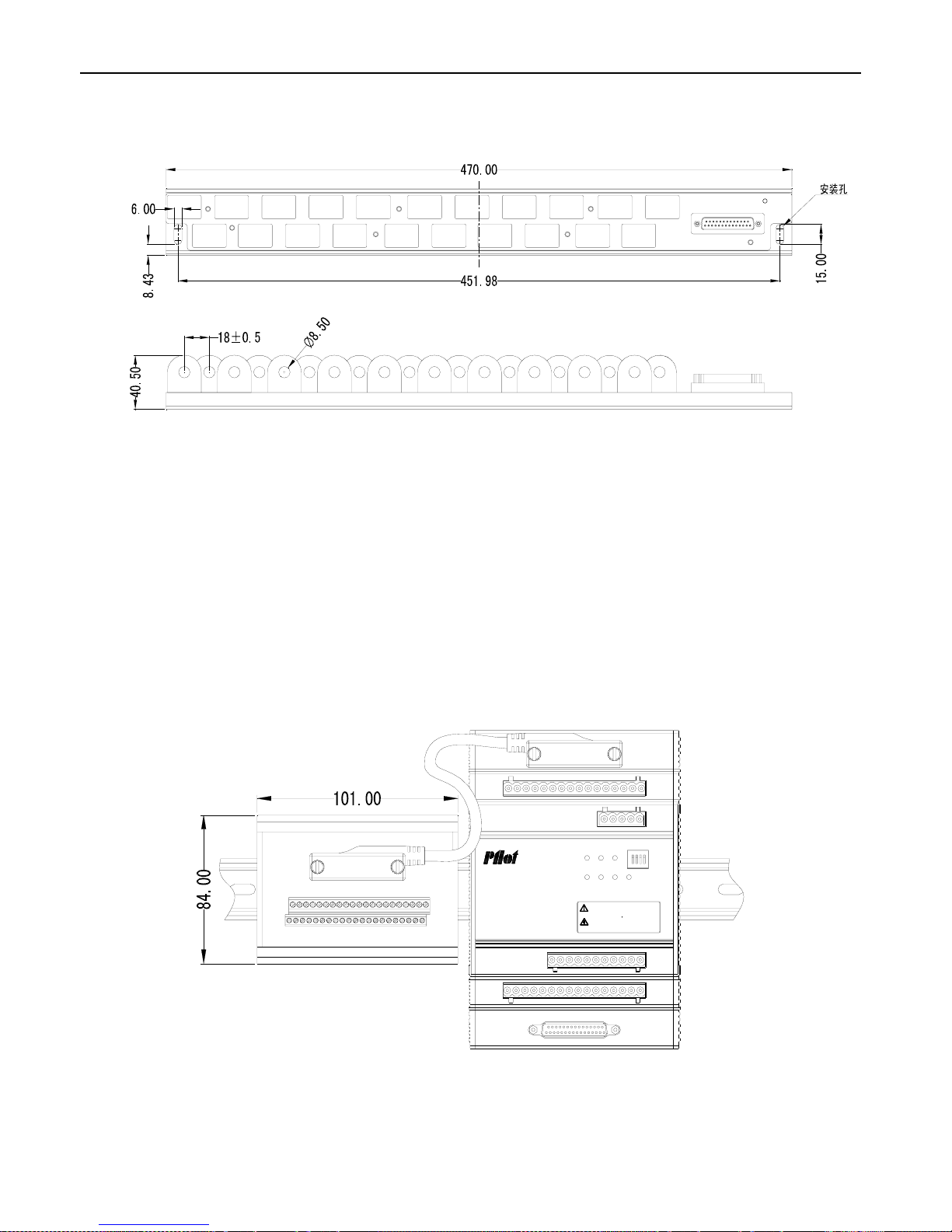
3.3 CT Module Installation Index
Picture 3.7 CT Module Index
3.4 Outgoing Single Installation CT Index
3.4.1 CT Switching Module Index
Power Run Com
S1
S2S3S4
ADDR
MAIN UNIT
本设备的安装和维护仅能由经过培训的专业人员
进行。
对设备进行安装操作前 应断开电源,打开所有
电压互感器二次绕组和短路所有电流互感器二次
绕组。不遵守适当的预防措施,可能导致严重触
电事故。
Picture 3.8 CT Switching Module Index
Page 16
PMAC202 BCPM User Manual · 13
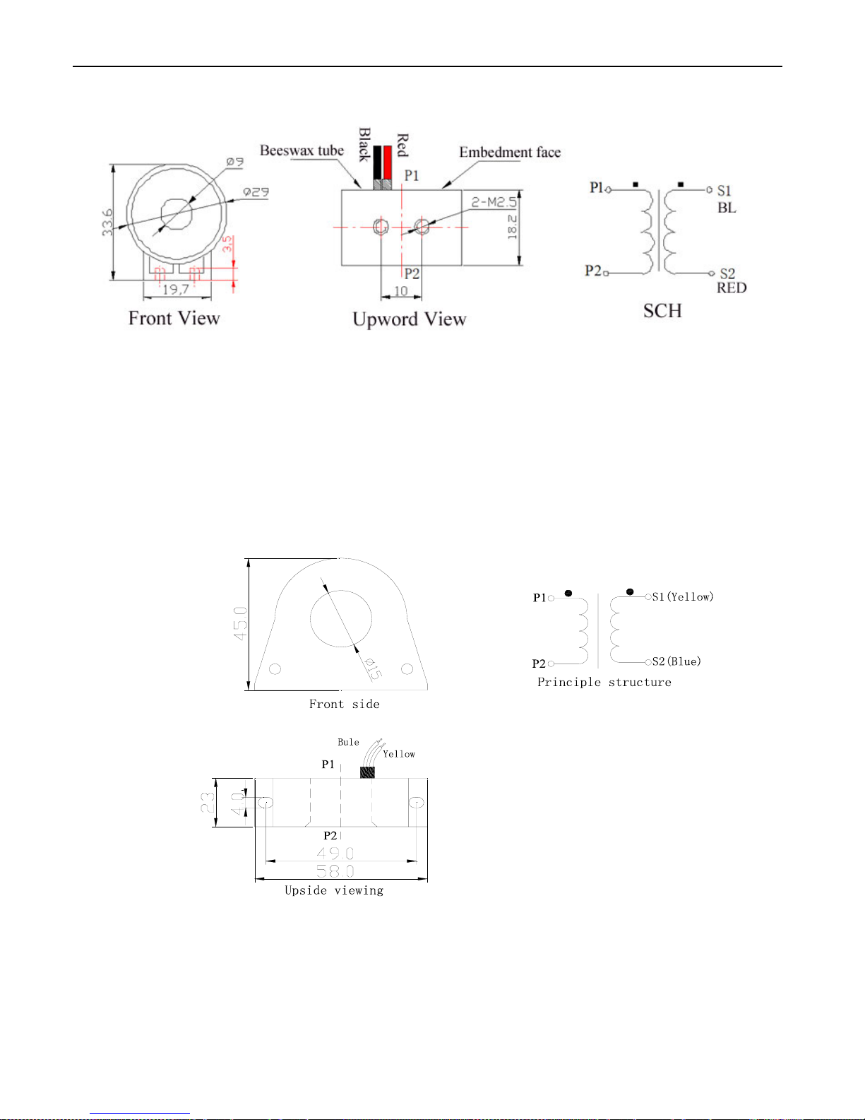
3.4.2 50A Single CT Index
Picture 3.9 50A Single CT Index
[Note]:
Each CT equip with 2.5M cable, Black cable connect with CT Switching module same terminal. One CT Switching
module can connect with 21 CT, 50A single CT be fixed by 2 M3*8 screw from bottom to rear panel
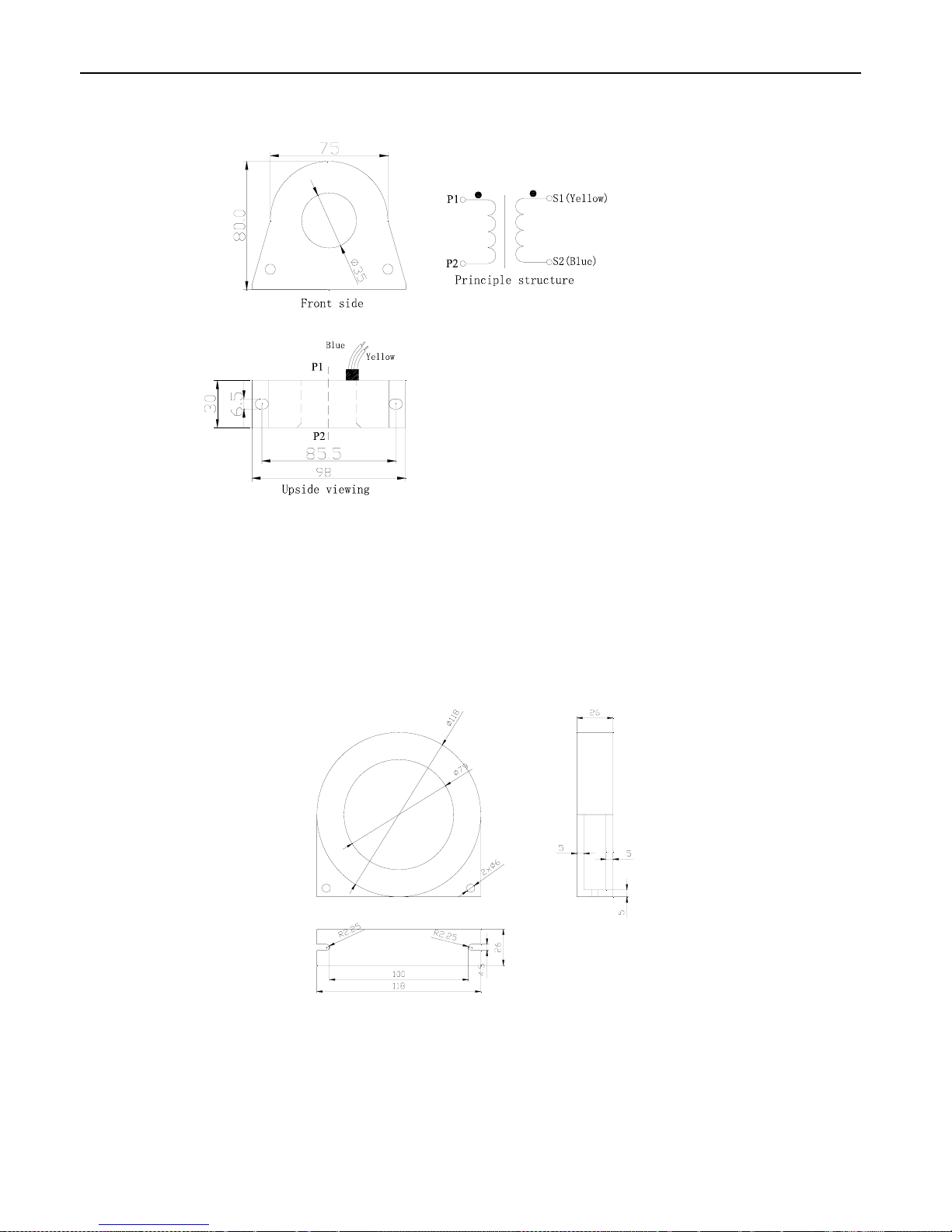
3.4.3 100A Single CT Index
Picture 3.10 100A Single CT Index
[Note]:
Each CT equip with 2.5M cable, Yellow cable connect with CT Switching module same terminal. One CT Switching
module can connect with 21 CT, 100A single CT be fixed by 2 M3*8 screw from bottom to rear panel
Page 17
PMAC202 BCPM User Manual · 14
3.4.4 200A Single CT Index
Picture 3.11 200A Single CT Index
[Note]:
Each CT equip with 2.5M cable, Yellow cable connect with CT Switching module same terminal. One CT Switching
module can connect with 21 CT, 200A single CT be fixed by 2 M3*8 screw from bottom to rear panel
3.5 Incoming Line Leakage Current Transformer Index
Picture 3.12 Incoming Line Leakage Current Transformer
[Note]: Incoming Line Leakage Current Transformer standard is 250A
Page 18
PMAC202 BCPM User Manual · 15
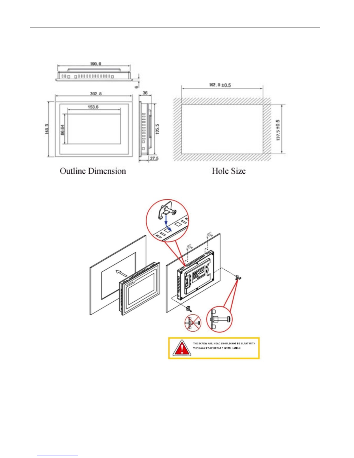
3.6 HMI Module Index
Picture 3.13 HMI Module Index
Picture 3.14 HMI Installation
[Note]: HMI Embedded panel mounting
Page 19

PMAC202 BCPM User Manual · 16
4. Connection Wiring
4.1 Main Module Terminals
No
Definitio
n
Instruction
No
Definition Instruction
1 VA
Incoming Line Voltage
measurement input
25 485A+
1
st
RS485 communication to Status
module
2 NC 26 SHLD
3 VB 27 SHLD
2
nd
RS485 communication to HMI 4 NC 28 485B-
5 VC 29 485B+
6 VN 30 SHLD
3
rd
RS485 communication to System 7 IN1
Null Line Current
31 485C-
8 IN2 32 485C+
9 IA1*
Incoming Line Phase A
Current, * for the same
terminal
33 VN
Null-GND line voltage measurement
input
10 IA2 34 VG
11 IB1*
Incoming Line Phase B
Current, * for the same
terminal
35 PT-
PT100 input
12 IB2 36 PT+
13 IC1*
Incoming Line Phase C
Current, * for the same
terminal
37 RL21
Relay 2
14 IC2 38 RL22
15 I△+
Leakage Current
39 RL11
Relay 1
16 △I - 40 RL12
17 24V2-
24V DC power supply 2
41 Pulse-
kWh Pulse output
18 24V2+ 42 Pulse+
19 NC Null 43 NC Null
20 24V1-
24V DC power supply 1
44 S4
1-4 DI Status
21 24V1+ 45 S3
22 24VO-
24V DC power output
46 S2
23 24VO+ 47 S1
24 485A- 1st RS485 communication 48 DC DI Status Common Terminal
Page 20
PMAC202 BCPM User Manual · 17
4.2 Switching Value Module Terminals
No
Definition
Instruction
No
Definition
Instruction
1 24V+
Positive pole of 24V power supply
input
17 24V+
Positive pole of 24V power supply
output
2 24V-
Negative pole of 24V power supply
input
18 24V-
Negative pole of 24V power supply
output
3 SHLD Shielded earth 19 SHLD Shielded earth
4 485A- 485 - 20 485A- 485 -
5 485A+ 485 + 21 485A+ 485 +
6 S1 DI 1 Input 22 S12 DI 12 Input
7 S2 DI 2 Input 23 S13 DI 13 Input
8 S3 DI 3 Input 24 S14 DI 14 Input
9 S4 DI 4 Input 25 S15 DI 15 Input
10 S5 DI 5 Input 26 S16 DI 16 Input
11 S6 DI 6 Input 27 S17 DI 17 Input
12 S7 DI 7 Input 28 S18 DI 18 Input
13 S8 DI 8 Input 29 S19 DI 19 Input
14 S9 DI 9 Input 30 S20 DI 20 Input
15 S10 DI 10 Input 31 S21 DI 21 Input
16 S11 DI 11 Input 32 SG DI Status Common Terminal
4.3 CT Module Terminals
One CT module can connect with 21 branch circuits, each branch circuit cross the CT follow by phase ABC and
repeated as below:
Page 21
PMAC202 BCPM User Manual · 18
4.4 HMI Power Connection
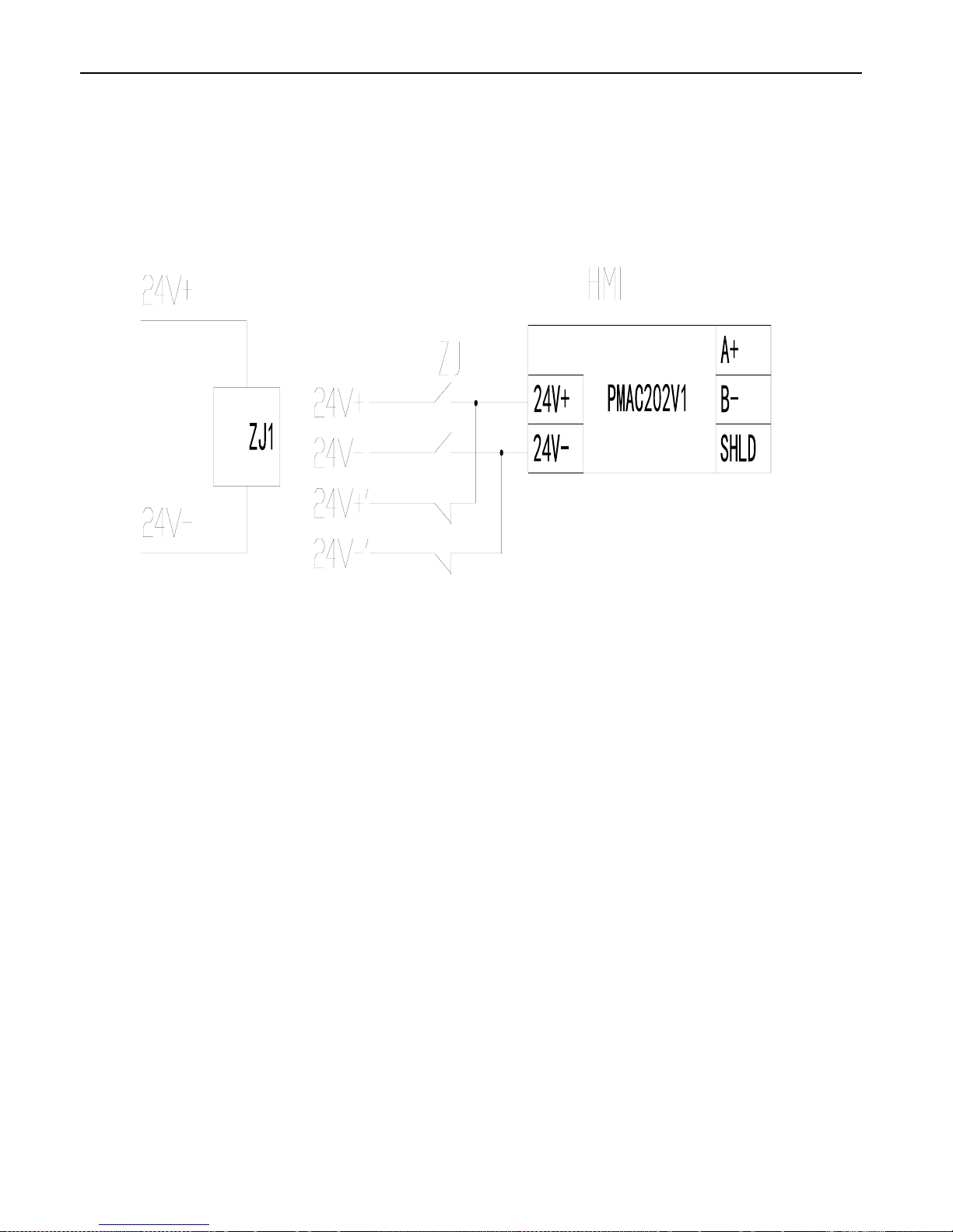
HMI Power Supply is DC 24V, there are two kinds connection wiring:
1. If there is no Status Module, power supply from Main Module 24V DC power supply output terminal
2. If has Status module, power supply from last status module 24V DC power supply output terminal
For Two way Imcoming line can exchange HMI power supply by one 24V relay, as following picture:
Page 22
PMAC202 BCPM User Manual · 19
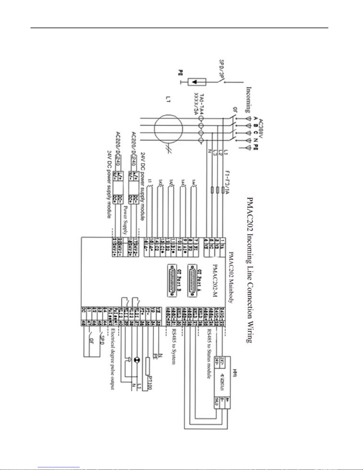
4.5 Incoming Line Connection Wiring
Page 23
PMAC202 BCPM User Manual · 20
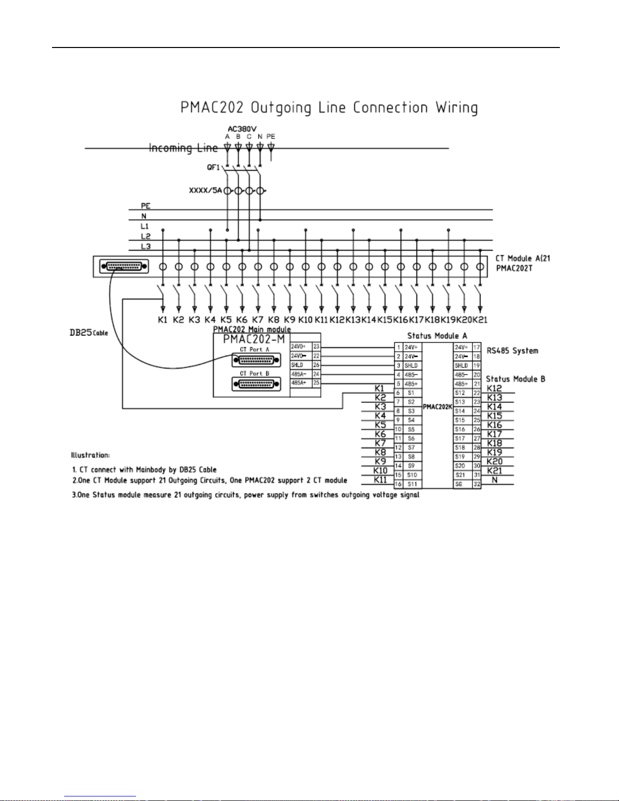
4.6 Outgoing Line Connection Wiring
Note: When there is just one 21 loop CT module, the CT module just can connect with Main module PortA
Page 24
PMAC202 BCPM User Manual · 21
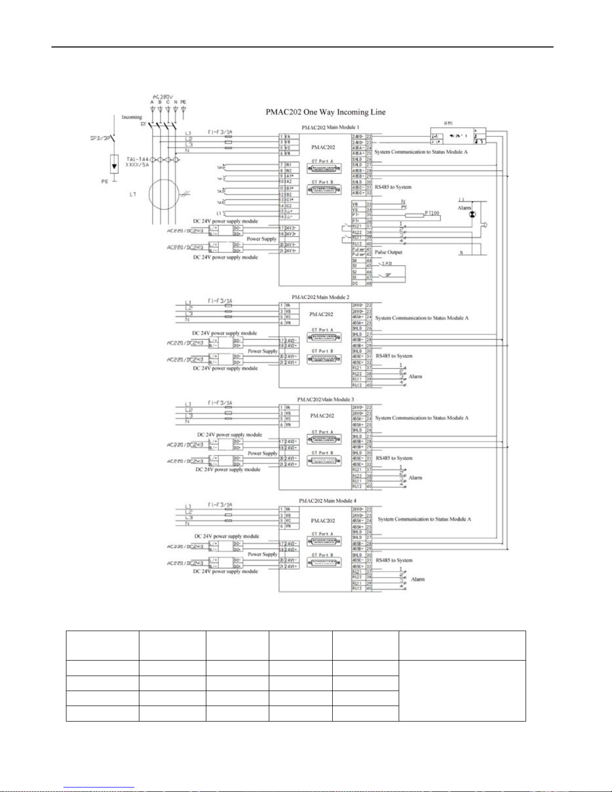
4.7 One Way Incoming Line System Connection Wiring
Different Outgoing Line Circuits Configuration table:
Outgoing
Line Circuits
Main
Module 1
Main
Module 2
Main
Module 3
Main
Module 4
Note
21 or 42
■ □ □ □ ■Configuration needed
□Configuration no need
63 or 84
■ ■ □ □
105 or 126
■ ■ ■ □
147 or 168
■ ■ ■ ■
Page 25
PMAC202 BCPM User Manual · 22
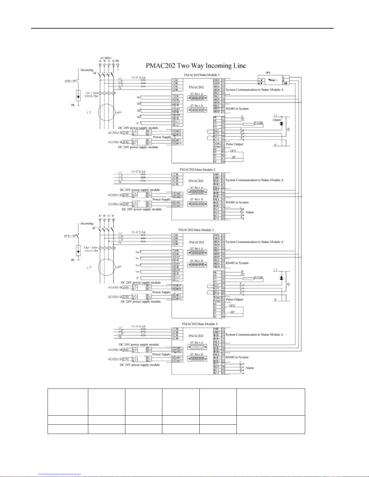
4.8 Two Way Incoming Line System Connection Wiring
Different Outgoing Line Circuits Configuration table:
Outgoing
Line
Circuits
Main
Module 1
Main
Module 2
Main
Module 3
Main
Module 4
Note
21 or 42
■ □ ■ □ ■Configuration needed
□Configuration no need
63 or 84
■ ■ ■ ■
Page 26
PMAC202 BCPM User Manual · 23
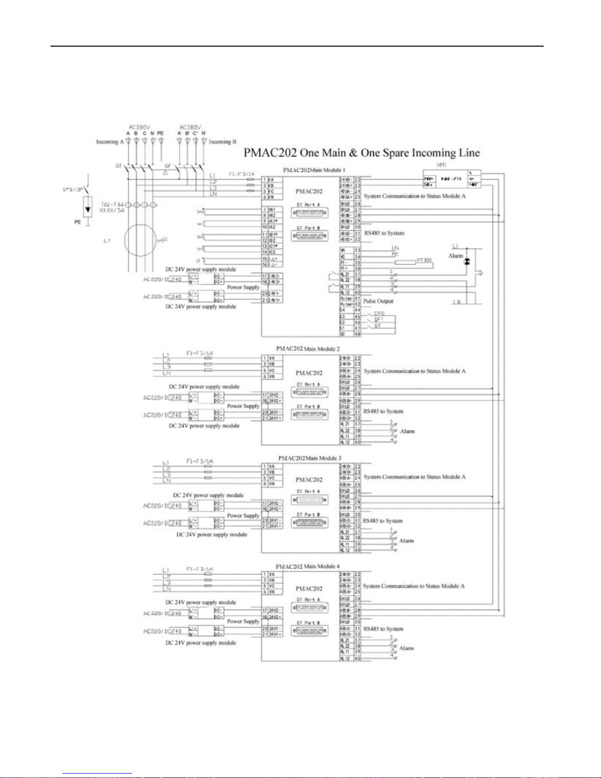
4.9 One Main & One Backup Incoming Line System Connection Wiring
Page 27
PMAC202 BCPM User Manual · 24
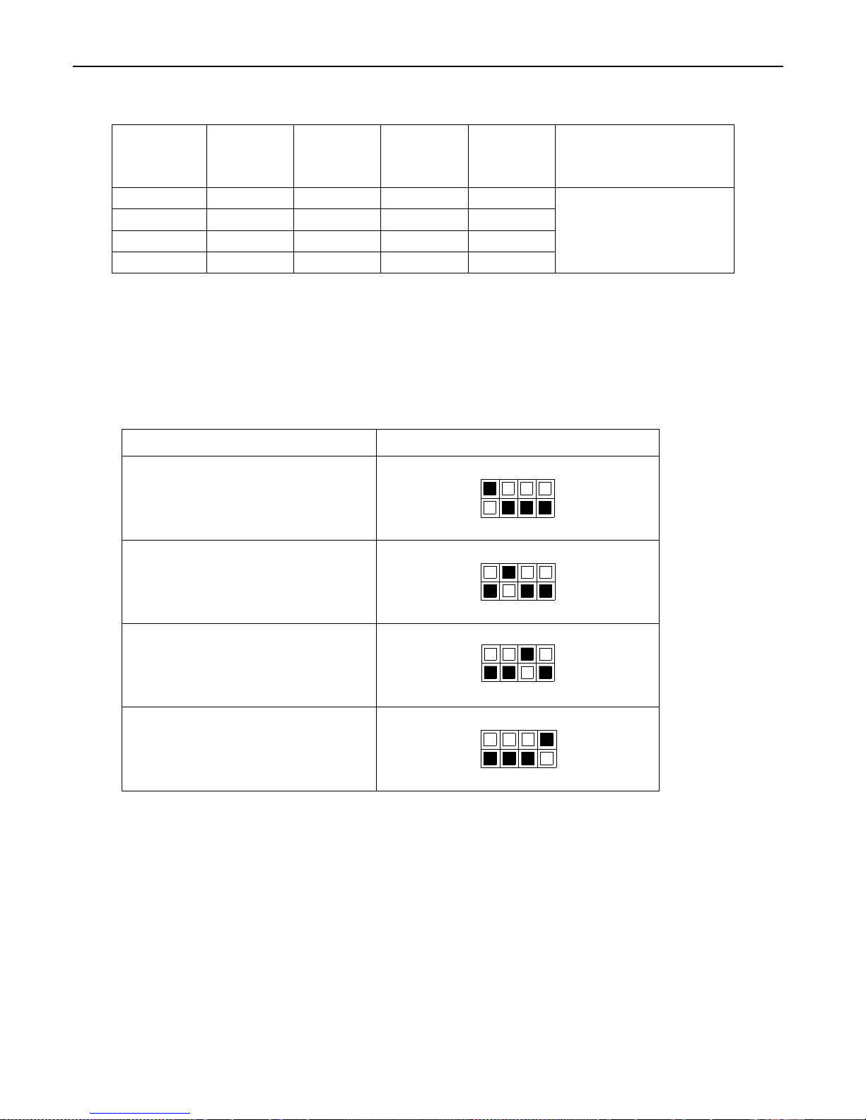
Different Outgoing Line Circuits Configuration table:
Outgoing
Line
Circuits
Main
Module 1
Main
Module 2
Main
Module 3
Main
Module 4
Note
21 or 42
■ □ □ □ ■Configuration needed
□Configuration no need
63 or 84
■ ■ □ □
105 or 126
■ ■ ■ □
147 or 168
■ ■ ■ ■
4.10 Multi Main Module Address Setting
Module Main Module Dial Switch Setting
PMAC202 1
1 2 3 4
ON
PMAC202 2
1 2 3 4
ON
PMAC202 3
1 2 3 4
ON
PMAC202 4
1 2 3 4
ON
Page 28
PMAC202 BCPM User Manual · 25
5. Display and Operation
5.1 System Configuration
After Power On, power meter display real time data, under real time data interface, press “System Config” button to
enter into system configuration interface
Notice
After Power ON, should finish Incoming line mode selection and Outgoing line circuits selection setting first,
then to setting other parameters
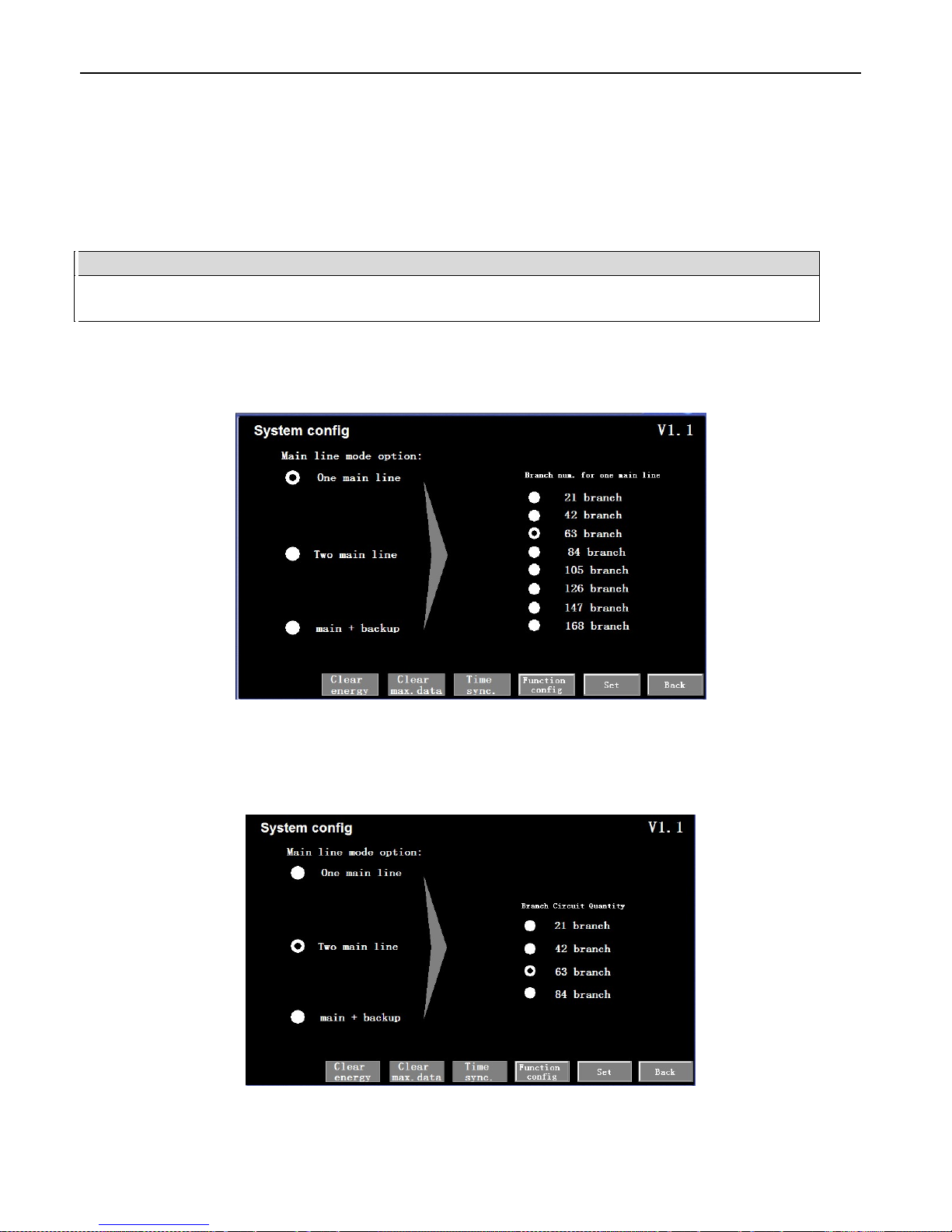
5.1.1 One way Incoming Line Configuration
Configuration as One way incoming line mode, as picture 5.1
Picture 5.1
5.1.2 Two way Incoming Line Configuration
Configuration as Two way incoming line mode, as picture 5.2
Picture 5.2
Page 29
PMAC202 BCPM User Manual · 26
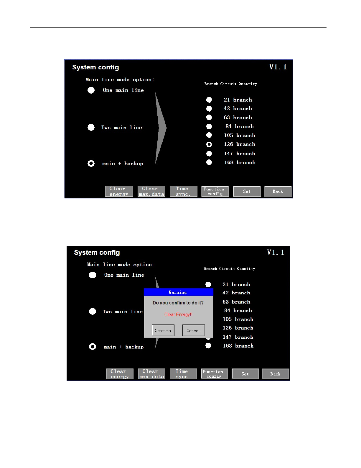
5.1.3 One Main & One Backup Incoming Line Configuration
Configuration as Main & Backup incoming line mode, as picture 5.3
Picture 5.3
5.1.4 Clear Energy
Clear Main Module Energy, as picture 5.4
Picture 5.4
Page 30
PMAC202 BCPM User Manual · 27
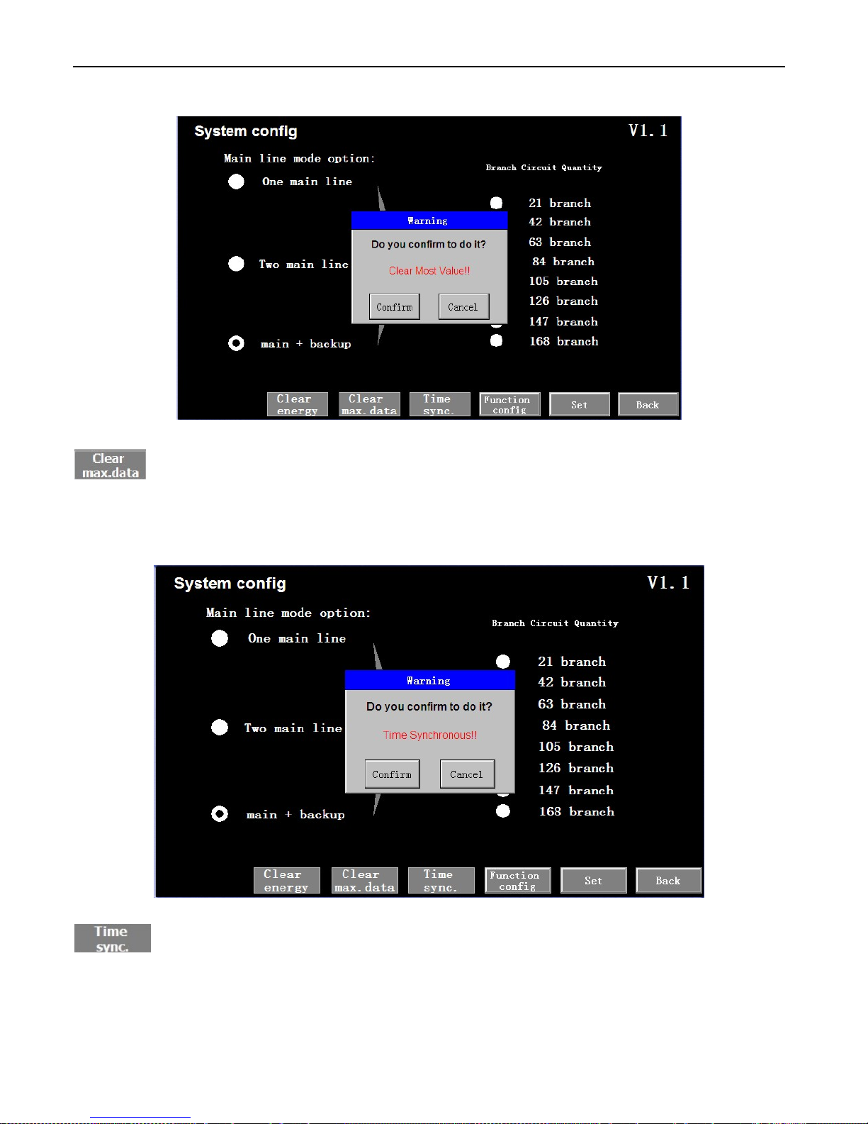
5.1.5 Clear Maxim Value
Clear all the Maxim value information in Main Module, e.g. Maxim Current value, Maxim Current
Demand etc
5.1.6 Time Synchronization
Synchronization time on HMI and Main Module
Page 31
PMAC202 BCPM User Manual · 28
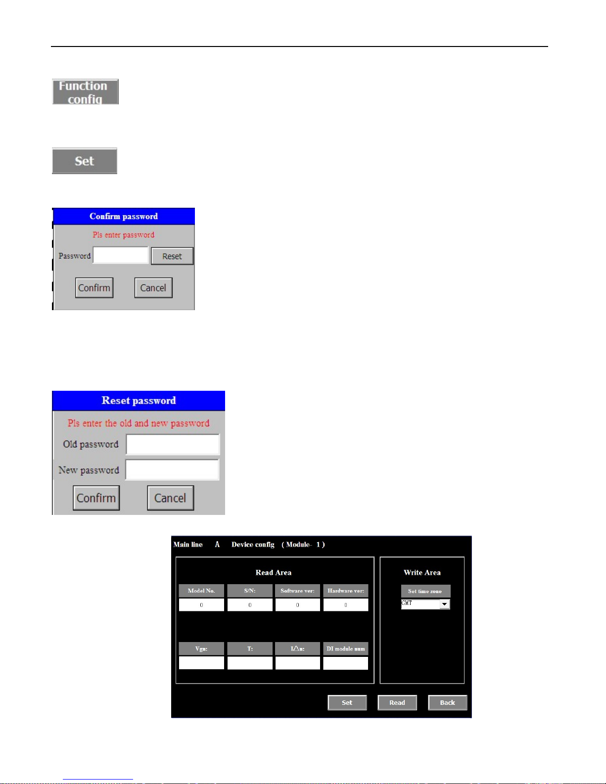
5.1.7 Function Configuration
Exchange to Information setting interface, as picture 5.5
5.1.8 Setting
Press SET, after input correct password for further operation
5.1.9 Password Input
when setting Incoming line Clear Maxim value, Time Synchronization, Function
Configuration, Set system configuration, password input table will be shown, further operation can be processed
after input correct password. Default password: 201
5.1.10 Password Modification
Device Information setting interface:
Picture 5.5
Page 32
PMAC202 BCPM User Manual · 29
5.2 Data Display
5.2.1 Real Time Data Display
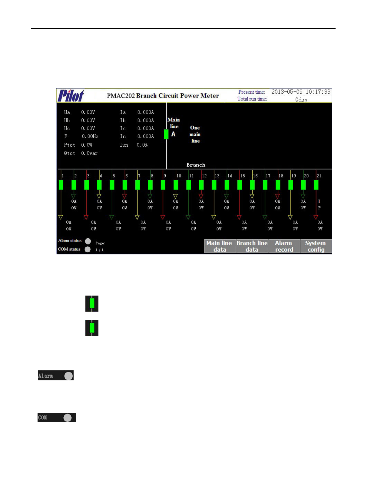
Power on the display module you can enter into main interfaced display as below picture 5.6, Display real-time data
of one or two incoming line circuit and 21 branch outgoing circuit as well as the status of switch.
Picture 5.6
5.2.2 Switch status display
Incoming Switch: Is the condition of Incoming Line switch 1 status, green means “OFF”, red means “ON”.
flash means Out-of-Order
Outgoing Switch: Is the condition of Switch, green means “OFF”, red means “ON”. flash means
Out-of-Order
5.2.3 Alarm display
The alarm light will turn red and flash when event happen. Gray means no alarm.
5.2.4 Communication Status Indicate
Green means the communication between display module and main module is normal. Gray
means no communication.
Page 33
PMAC202 BCPM User Manual · 30
5.2.5 Key Operation
Next: Exchange to next System Interface
Incoming Data: Exchange to Incoming data display interface
Outgoing Data: Exchange to Outgoing data display interface
Alarm Record: Exchange to Real-time alarm record interface
System Configuration: Exchange to system configuration interface
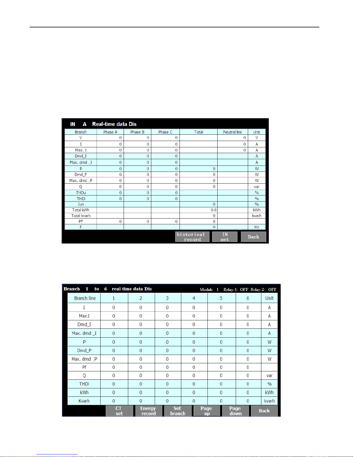
5.3 Incoming Circuit Data Display
Display 1 loop incoming circuit real time data, as picture 5.7
Picture 5.7
5.4 Outgoing Circuit Data Display
Display multi loop outgoing circuit real time data, as picture 5.8
Picture 5.8
Page 34
PMAC202 BCPM User Manual · 31
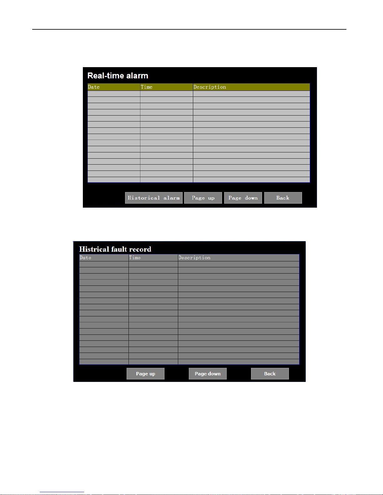
5.5 Real-time Alarm Record Display
Display Maxim 16 pieces alarm information, as picture 5.9
Picture 5.9
History Information Record:
Picture 5.10
Page 35
PMAC202 BCPM User Manual · 32
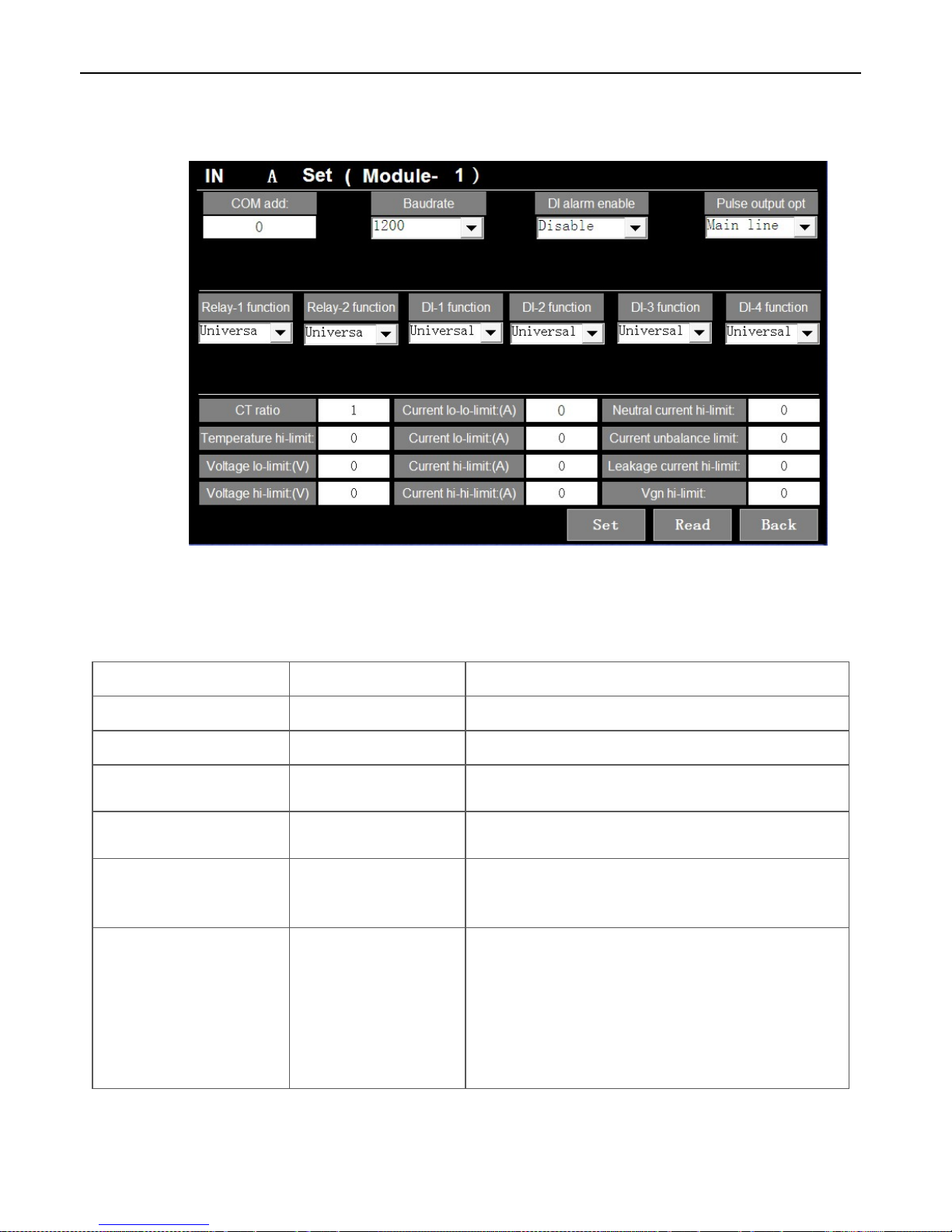
5.6 Incoming Circuit Value Programming
Configure Incoming line circuit parameters and alarm value, as picture 5.11
Picture 5.11
Items Range of data Definition
Communication Add
1~247
Initial value is 1
CT Ratio
1~100
Initial value is 1
Baud Rate
1200、2400、4800、9600、
19200 or 38400
Initial value is 19200
DI Alarm Enabled
Enable, Disable
Enable: Permit DI alarm
Disable: Forbid DI alarm
Pulse Output Option
Main line, Branch 1-42
Incoming Circuit: Energy pulse output option is incoming
Outgoing Circuit: Energy pulse output option to each relative
outgoing circuit
Relay function
Universal Relay
RUN Indication
Alarm
In Alarm
Out Alarm
Universal relay: can be controlled by Modbus function code 05.
Equipment working instruction: act after equipment work.
Alarm output: act after main or branch circuit alarm.
Incoming line branch circuit alarm: act after main circuit alarm.
Outgoing line branch circuit alarm: act after branch circuit
alarm.
Relay initial setting: Relay 1 & 2 are all alarm output
Page 36

PMAC202 BCPM User Manual · 33
Switch Status function
Universal switch, Incoming
line switch, Surge
protection switch
Surge protection switch: Incoming line switch status can be
setting as lighting protection switch, after setting, the main
interface will has a lighting protection switch display. If the
switch OFF then means the lighting protection switch OFF
Current low-low level alarm
value
5~650A, 0 means alarm
closed
Alarm action: over 0 and less than setting value.
Alarm reset: delay 5s after the alarm condition is eliminated.
Current low level alarm value
5~650A, 0 means alarm
closed.
Alarm action: over low-low level alarm value and smaller than
setting value.
Alarm reset: delay 5s after the alarm condition is eliminated.
Current high level alarm value
5.0~650A, 0 means alarm
closed.
Alarm action: over the setting value and smaller than low-low
level alarm value.
Alarm reset: delay 5s after the alarm condition is eliminated.
Current high-high level alarm
value
5.0~650A, 0 means alarm
closed.
Alarm action: over the setting value.
Alarm reset: delay 5s after the alarm condition is eliminated.
Neutral current high level
alarm value
5.0~650A, 0 means alarm
closed.
Alarm action: the current value is over the setting value.
Alarm reset: delay 5s after the alarm condition is eliminated.
Current unbalance rate alarm
value
5.0~100%, 0 means alarm
closed.
Alarm action: over than the setting value.
Alarm reset: delay 5s after the alarm condition is eliminated.
Unbalance calculation formula:
(Imax-Imin)/Imax×100%
Imax: 3 phase current maxim value
Imin: 3 phase current minimum value
Voltage low level alarm value
20~300V, 0 means alarm
closed.
Alarm action: over 0 and smaller than setting value.
Alarm reset: delay 5s after the alarm condition is eliminated.
Voltage high level alarm value
20~300V, 0 means alarm
closed.
Alarm action: over the setting value.
Alarm reset: delay 5s after the alarm condition is eliminated.
Temperature high level alarm
value
30--120, 0 means alarm
closed.
Alarm action: over the setting value.
Alarm reset: delay 5s after the alarm condition is eliminated.
Leakage current high level
alarm value
0.1—1A, 0 means alarm
closed.
Alarm action: over the setting value.
Alarm reset: delay 5s after the alarm condition is eliminated.
Null-Earth voltage high level
alarm value
2—10V, 0 means alarm
closed.
Alarm action: over the setting value.
Alarm reset: delay 5s after the alarm condition is eliminated.
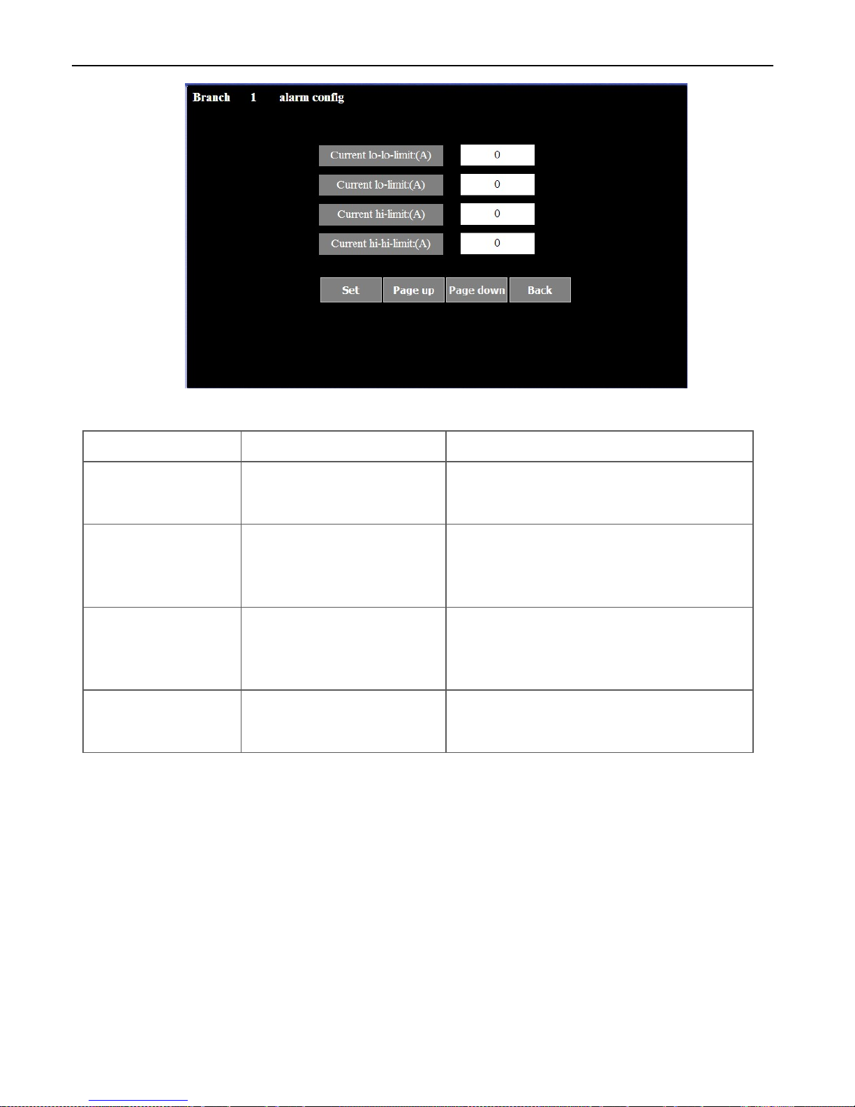
5.7 Outgoing Circuit Value Programming
Outgoing circuit alarm setting as picture 5.12
Page 37
PMAC202 BCPM User Manual · 34
Picture 5.12
Items Parameter Definition
Current low-low level alarm
value
5.0~250.0A,0 means alarm closed.
Alarm action: over 0 and smaller than setting value.
Alarm reset: delay 5s after the alarm condition is
eliminated.
Current low level alarm
value
5.0~250.0A,0 means alarm closed.
Alarm action: over the low-low level alarm value and
smaller than setting value.
Alarm reset: delay 5s after the alarm condition is
eliminated.
Current high level alarm
value
5.0~250.0A,0 means alarm closed.
Alarm action: over the setting value and smaller than
high-high level alarm value.
Alarm reset: delay 5s after the alarm condition is
eliminated.
Current high-high level
alarm value
5.0~250.0A,0 means alarm closed.
Alarm action: over the setting value.
Alarm reset: delay 5s after the alarm condition is
eliminated.
Page 38
PMAC202 BCPM User Manual · 35
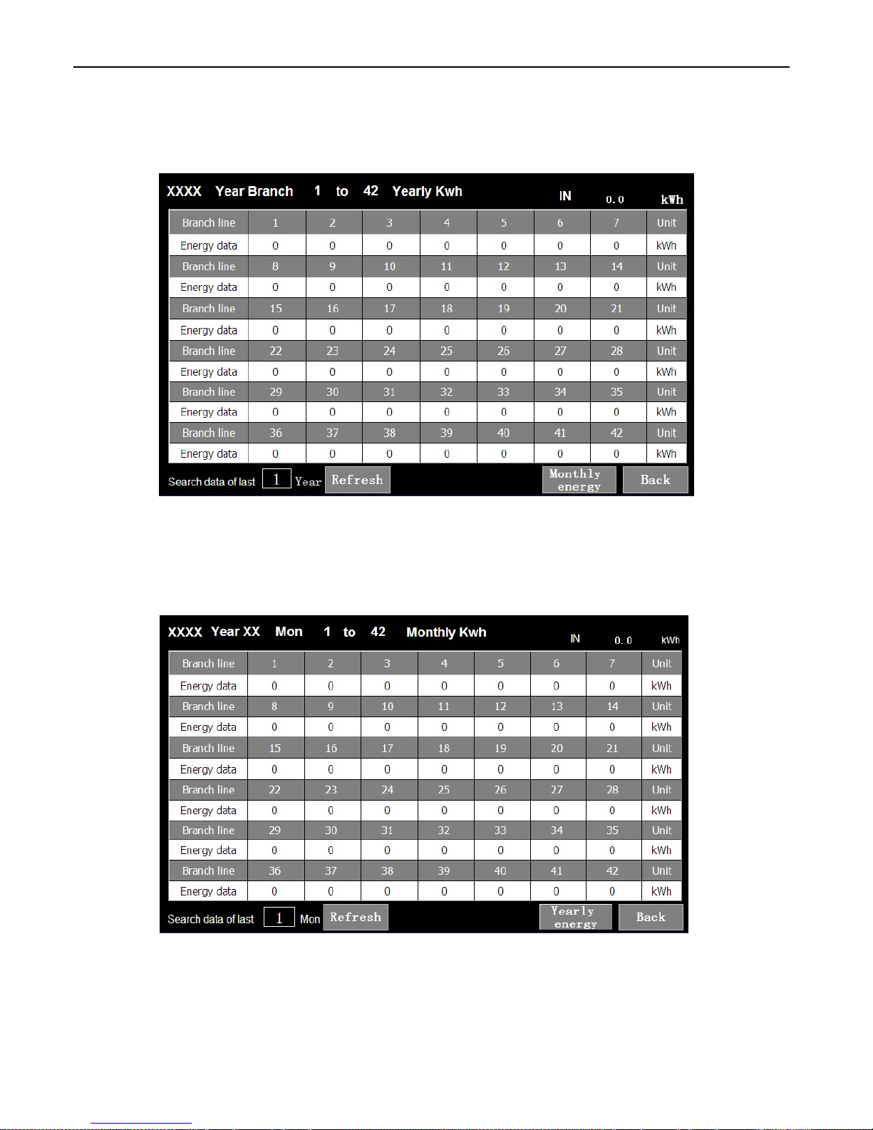
5.8 History Electrical Degree
Display historical Year electrical degree value, as picture 5.13
Picture 5.13
Display historical Month electrical degree value, as picture 5.14
Picture 5.14
Page 39
PMAC202 BCPM User Manual · 36
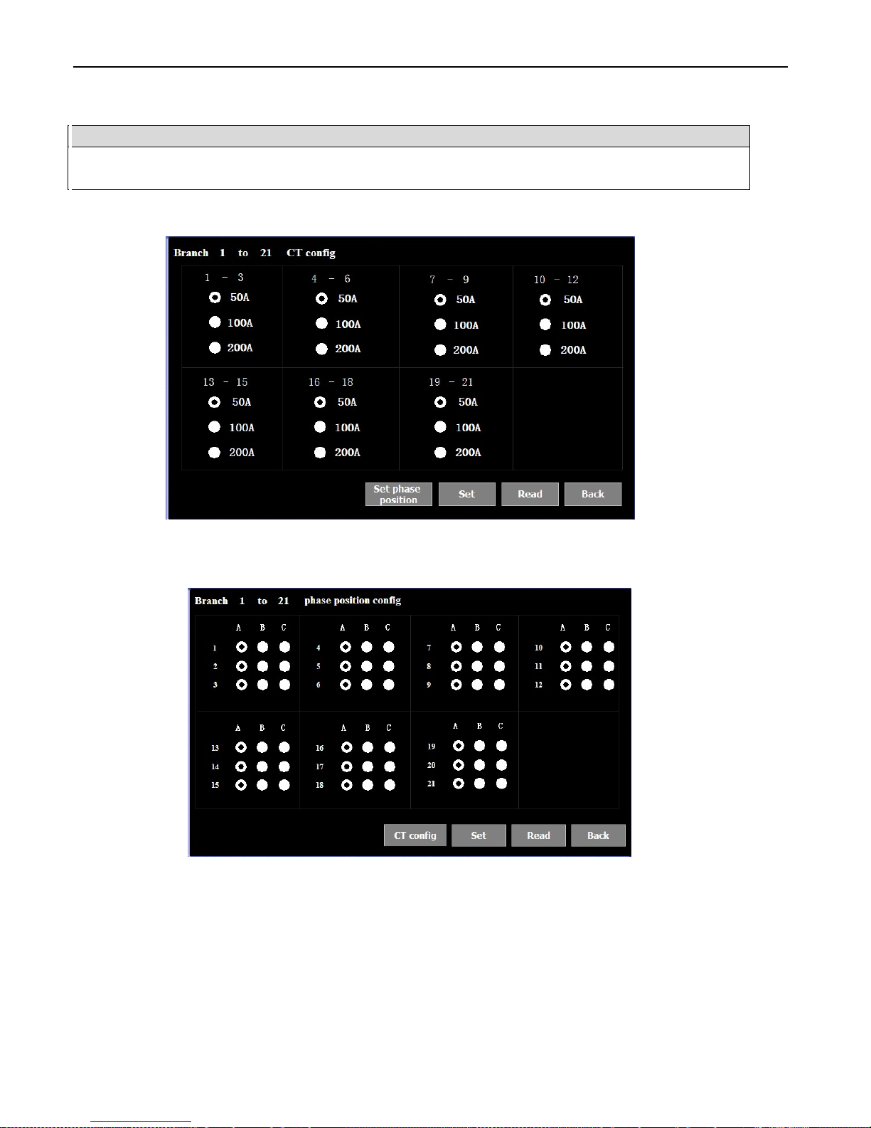
5.9 CT Setting
Notice
CT specification will be effective after be revised need power ON again, revise phase position configuration
no need re-power on, please make sure connection sequence and configuration correspondence
Display CT specification as picture 5.15
Picture 5.15
Phase position configuration interface
Picture 5.16
Page 40
PMAC202 BCPM User Manual · 37
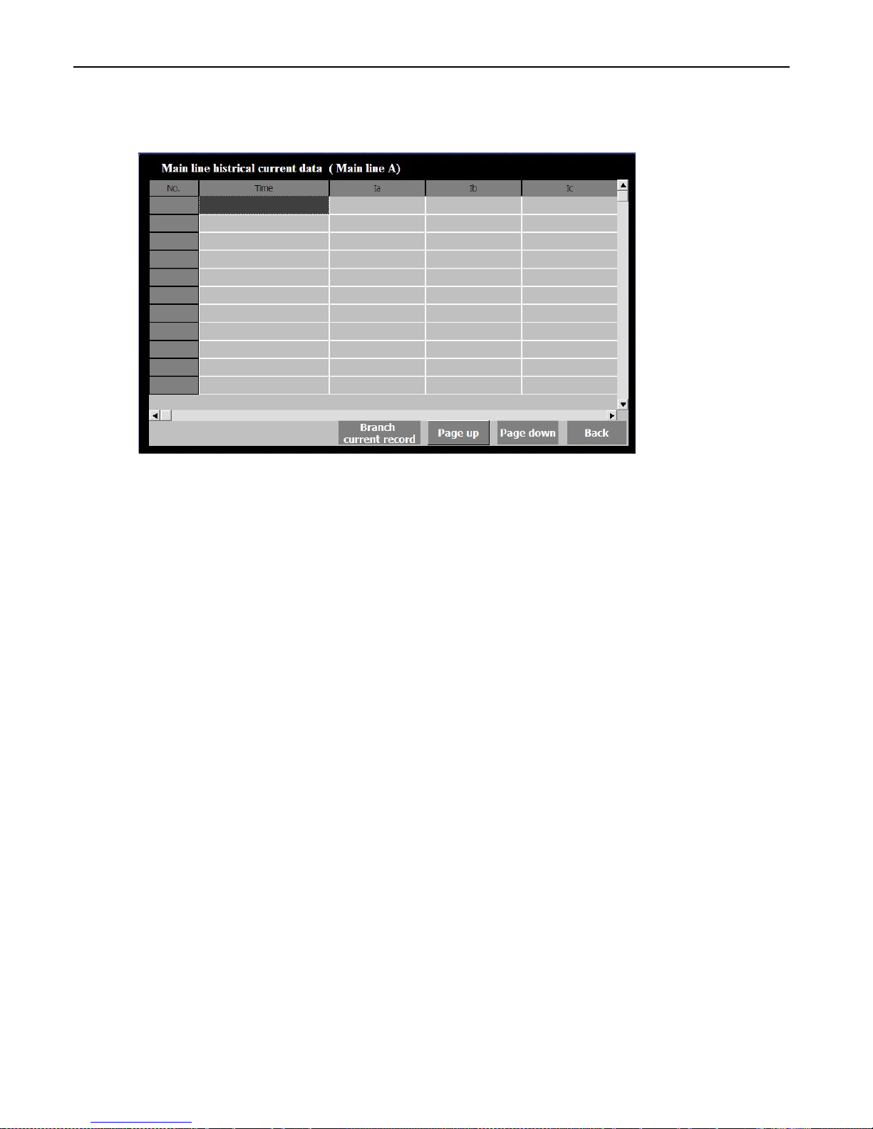
5.10 Data Record
Record incoming line current value, each 20 minutes record one time, as picture 5.17
Picture 5.17
Page 41

PMAC202 BCPM User Manual · 38
6. Maintenance and Trouble Shooting
Possible Question Possible Reason Solutions
Device no display after add
control source
The power did not add to the
device
Check the power supply terminals on device
to make sure whether add correct operating
voltage
Check the source control fuse not be burned
Measuring value not correct
or non-conformance with
expect value
Voltage measurement not
correct
Check measuring voltage whether match
with rated parameter
Check connection wiring
Current measurement not
correct
Check measuring current whether match
with rated parameter
Check CT parameter
Check connection wiring
Power measurement not
correct
Check voltage / current phase sequence
Check current dotted terminal
Check CT phase sequence
Outgoing Circuit Switch
Status no operation
Status module
communication stop
Check status module communication
indicate light
Check status module communication
connection wiring
Switch status operation
voltage incorrect
Check outside node types whether match
with device rated parameter
Check outside connection wiring
Main module can not
connect with Host computer
Communication address
incorrect
Check device communication address
Communication baud rate
incorrect
Check device communication baud rate
Communication interference Check communication shield layer
Communication stop Check communication cable
System configuration not
match with main module
Check system configuration
Check main module dial switch
 Loading...