

Page 1
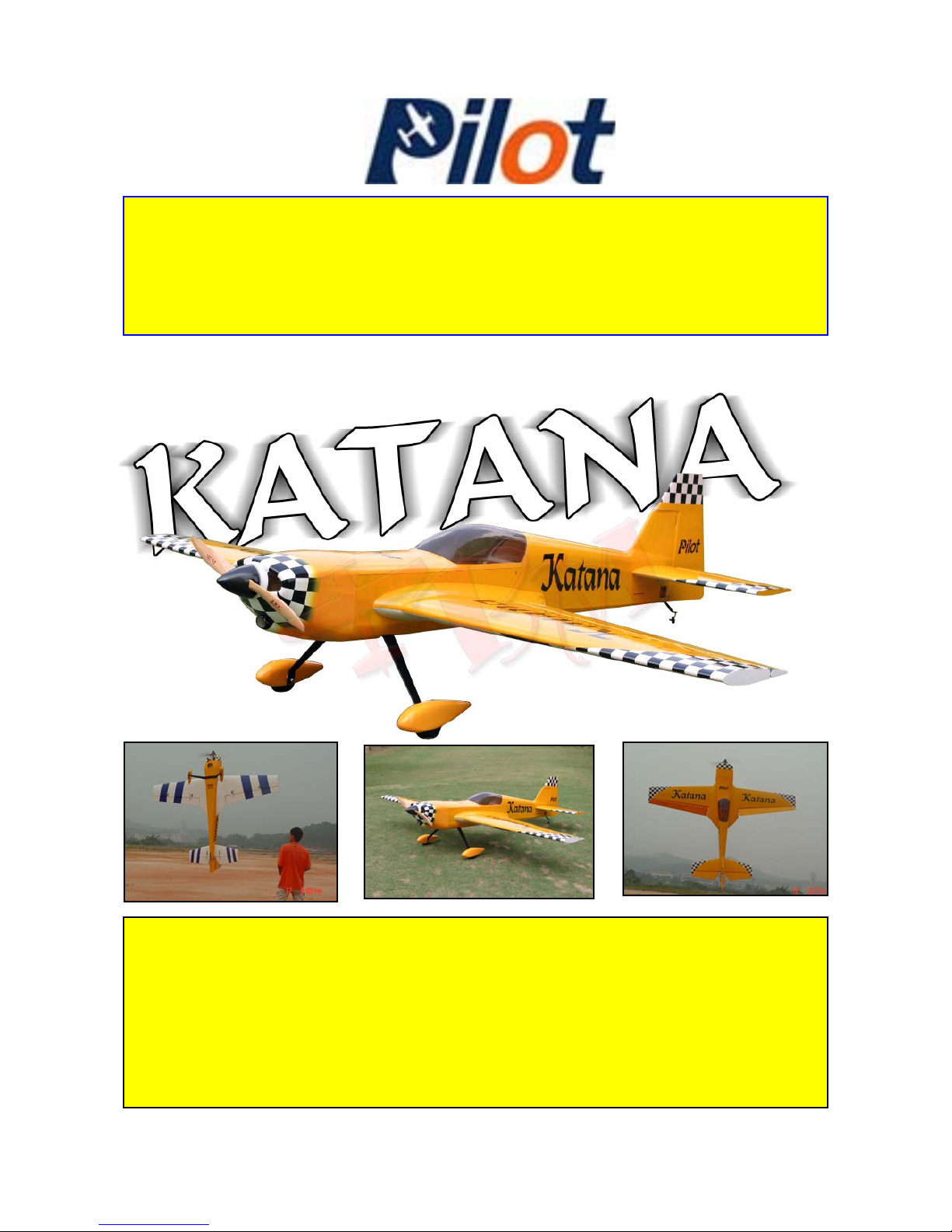
35% Katana
Wing Area: 2170 sq in (14000 sq cm)
Note: All construction photos by: Stephen Cinch
Wingspan: 106 in(2.69M)
Fuselage length: 93 in (2.36M)
Weight: 27.3 lbs (12.4kg)
Engine: 100CC
Page 2

Fore Word:
Every attempt has been made in this manual in word and picture to
help the modeler assemble this model, it is for advance modelers
with advanced knowledge of the needs and strength needed to complete a reliable and aerobatic plane.
If you do not have the skills ask a fellow modeler to help you with
this model assembly especially if it is your first large scale project.
Every engine you select posses a new adjustment of the firewall
placement and balance requirement due to the weight of the engine
and how it effects the CG (Center of Gravity) Therefore, you may
need to reposition the firewall by removing the screws from the aluminum angles, re-drill the mount holes and adjust to fit the length of
your engine in relationship to the cowl and the clearance needed to
clear the back plate of the spinner you have selected to use. Make
sure to measure the original angle of the firewall for proper right
thrust.
If you need help, don’t hesitate to email us your questions by going
to our web site: www.troybuiltmodels.com
Page 3
Construction and Assembly Manual for 35% Katana
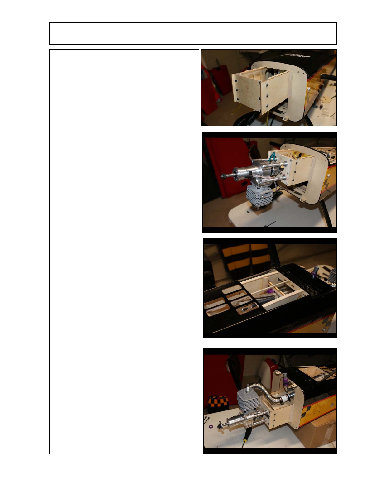
Engine Installation
Start by installing the engine making sure that
the mount is in the exact location by extending
the lines from the alignment “+” marked on the
firewall. This is very important or you cowl
will not line up with the engine. It is a good
idea to temporarily attach the engine to the firewall with self taping drywall screws and trial fit
the cowl before permanently attaching the engine. Paint the entire torque box and surrounding area with 15 minute epoxy that has be
thinned 20% with alcohol for fuel proofing
Measure the distance to the firewall to the front
of the cowl. Add stand offs to achieve the
proper distance. Use of washers or aftermarket
stand offs is recommended. Use 1/4 X 20 socket
head cap screws backed up with 1/4” fender
washers using blind nuts and nylon nuts. Use
blue Loctite on all screws. (You can build out
using epoxy plywood Laminate if you prefer,
but it adds weight)
By opening up the bottom of the plane and
making cooling exits help you access the area to
mount the muffler and help get rid of the excess
heat generated.
Now is the time to install the blind nuts for the
landing gear.
Now you can install the Exhaust manifold, muffler and exhaust pipe using 2 muffler supports
that you can epoxy in place supported by triangular hardwood supports. Bend the pipe (if
necessary) by having a friend help you.
Make sure the manifold is tight and use Red
Loctite on all engine bolts after reinstalling the
engine and muffler from fitting the cowl.
Attach the exhaust pipe to the fuselage at the
exit point to avoid any movement in the exhaust
system what-so-ever.
Remember to fuel proof the inside of the muffler area with thinned epoxy as well since there
will be some exhaust leakage.
2
Page 4
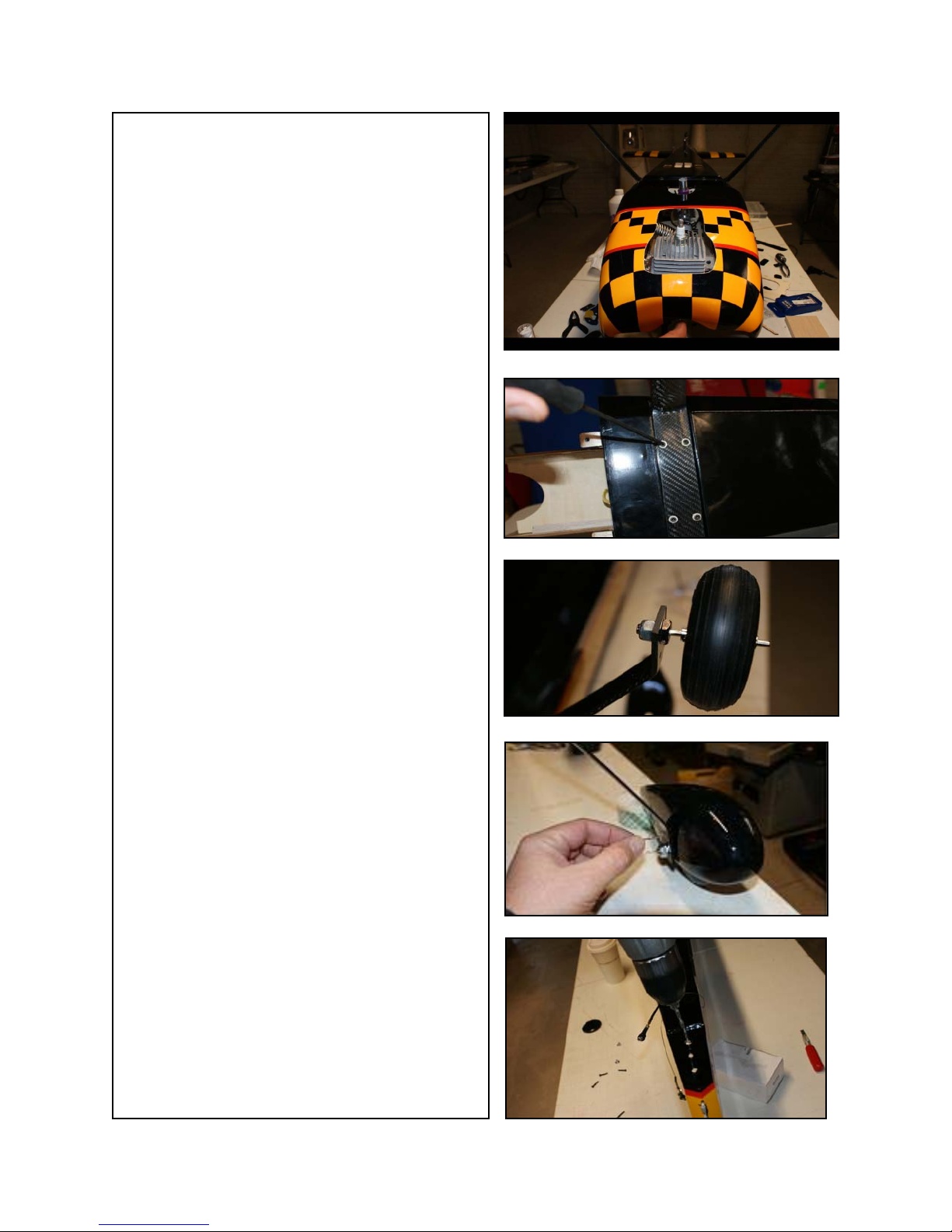
Cowl Installation
Using card stock or file folder thin cardboard
make the necessary cut outs for the engine head
and muffler. Make sure to tape the template
back far enough with masking tape that the cowl
can fit. Remove the engine & muffler. Now
slide on the cowl, screw it in place and mark the
cowl with a black grease pencil. Remove the
engine area using a large Dremel sanding drum
trail fitting as you go to make sure of the clearances.
You may also want to install baffling inside the
cowl at this time to direct the intake air over the
cooling fins for the engine. Use rubber washers
when mounting the cowl to avoid the metal
screws from eating bigger holes due to vibration.
Landing Gear
Install the landing gear with the bolts provided
and use blind nuts already installed and use blue
Loctite on the mounting bolts. (Optional Carbon
fiber gear shown)
Now install the landing gear axles making sure
that you file a flat spot on the axle for the Allen
screws to seat in place. Use blue Loctite on the
Allen screws.
Line the wheel pants up with the ground by slipping them over the axle and supporting them
from the rear for the proper clearance.
Drill the holes for the mounting bolts and then
removed and install the blind nuts.
Now mount the wheel pants with the bolts and
use blue Loctite on the threads.
Tail Wheel Installations
Drill holes in the hardwood tail wheel mount
and install the blind nut through the opening in
the rear of the fuse.
Install the mounting screw for the tail wheel using blue Loctite on the threads.
Install the hatch over the opening in the rear of
the stab with 4 screws
3
Page 5
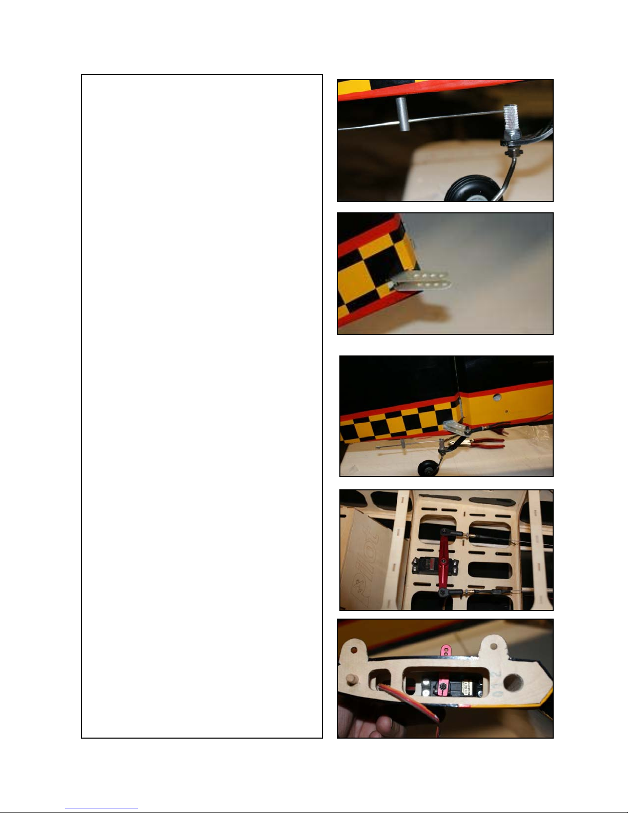
Bolt the tail wheel bracket in place and attach the
steering arm wire to the pivot as shown using Loctite on the Allen screws. The steering arm can be
inserted into the rudder steering tube at the time of
rudder installation.
Rudder Installation
Make sure to apply Vaseline to the rudder hinges to
prevent the epoxy from getting in to the joint.
Make sure to allow room for the 30 minute epoxy
to penetrate the hinges.
Install the epoxy rudder horns and glue in place but
make sure the holes line up by installing the rudder
steering bolts in place before the 30 minutes is up
and the epoxy has cured.
Finish up the rudder installation by installing the
rudder servo with the Air Wild metal servo arm
and the cable. Make sure the arm movement is just
slightly smaller than the arms on the rudder to prevent a slack cable. Loctite the cable turn buckles
and secure the steering cables with a loop into the
crimping sleeves.
Installing the Stabilizer
Install the elevator servo using a 1 1/2” metal servo
arm from Air Wild. Make sure to use Loctite on
the machine screws that hold the arm onto the
servo shaft.
Now install ball links on the servo arms with 4-40
bolts backed up with nylon lock nuts using Loctite
in the treads.
Check the clearance and the throw so there is no
binding of the arm.
Now install the elevator horn in the elevator using
30 minute epoxy and align the holes for the servo
push rod at the same time before the glue sets.
Now mount the elevator onto the stab making sure
you use Vaseline in the hinge points so the glue
will not stick the hinge shut.
Now install the 4-40 push rod and ball joints after
making sure the servo arm is
dead center.
4
Page 6
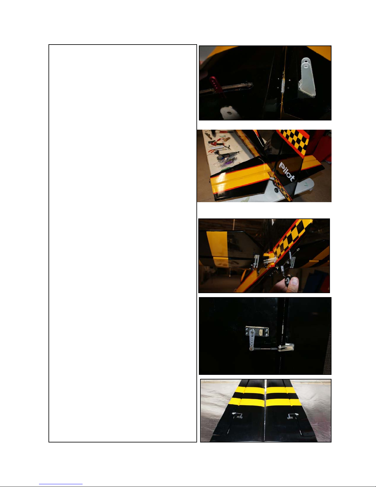
Install the stab mounting tubs and slide the stab
in place making sure to hook up the servo plug
to the 24 gauge servo extension wires and clip
the plugs together using safety clips.
Install the servo mount bolts with a washer, lock
washer and Loctite the blind nuts.
Now that the stab, tail wheel and elevators are
in place, check the alignment of the elevators
and rudder for throw and use sub trim to make
sure the elevators are perfect. Use about 30%
expo on the elevator and 70% on the rudder.
Wing assembly
Install the aileron horns in place with 30 minute
epoxy. Align the holes in the horns with the
ball joint mounting screws. Install the servo after pulling the servo extension wire in the wing.
Install a 1” metal servo arm on the servo and
Loctite it in place on the mount screw. Install
the 4-40 push rod and the horn.
Check for movement and center on the servo for
the aileron to be in a level resting position.
Check to make sure you have the servos in a reverse manner so ailerons with work properly.
Put the amount of movement recommended and
the end of this instruction manual.
The CG is located about the center of the wing
tube. Once you fly the plane, change the CG by
shifting the batteries to suit your flying style.
Typical throws are 15 degrees of elevator and
aileron and 30 degrees of rudder.
5
Instruction Manual by:
George Jenkins
Page 7

Set up for 35% Katana
CG at the center of the wing tube.
Aileron Movement: Low rate-15 degrees up and down
High Rate-30 degrees up and down
Rudder Movement: Low Rate-30 degrees left and right
High Rate-45 degrees left and right
Elevator Movement: 15 Degrees up and down
High Rate-25 Degrees up and down
Start at 40% exponential in all surfaces and adjust to your
6
type of flying demands.
COMPONENTS NEEDED TO COMPLETE THE KIT
Be sure to have all the parts on hand to hasten installation
- Engine: 100cc gasoline engine Note: DL 111 includes the muffler.
- Muffler: Pitts style muffler to fit your engine
- Propeller: 27×10, 26×12, 28×10
- Spinner: Included in kit
- Clevis: two Sullivan #562 4-40 snap links for choke and throttle
- Pushrods: two Sullivan #584 graphite push rods
- Throttle and choke servos: 30oz-in (2.2 kg-cm) minimum
- Aileron and Elevator servos: 4 total 120 oz-in (8.8 kg-cm) minimum
- Rudder servo: one 180 oz-in (13.2 kg-cm) minimum
- Aileron and Elevator servo arms: 1.50”
- Rudder servo arm: 3” not offset. Cross rudder wires.
- Elevator servo extensions: 36”
- Aileron servo extensions: 18” in wing, 3” in fuselage
- Batteries: 4.8 to 6 volt 2000mah for ignition. Two 2600mah for Receiver.
- Regulators and Switches: as required
Carbon Fiber accessories version:
• Carbon Fiber wing tube
• Carbon Fiber tail wing tube
• Carbon Fiber tail wheel
• Carbon Fiber spinner
Page 8
This is not a Toy! This R/C ARF kit and the model you build from this
kit is not a Toy!
It is capable of serious bodily harm and property damage. It is YOUR responsibility as your alone to assemble correctly, properly installing all R/C components
and fling gear (engine, tank, radio, pushrods, etc. and to test the model and fly it
only with experienced, competent help from an experienced pilot using commonsense and in accordance with national and international safety standards as
set forth by many Model Airplane Associations. It is suggested that you join
such an organization and adhere to there rule for safety of fellow pilots. If you
are just starting in R/C this in not the plane for you to learn how to fly. This is
not a beginners airplane but designed for advance pilots who know aerobatics. If
you need help contact a local hobby shop and purchase a trainer. Join a model
airplane club in your area and take lessons from a veteran R/C flight instructor.
Limits Of Responsibility: We accept no responsibility for crash damage. It is
impossible to determine for certain whether crash damage was the result of a radio system failure or pilot error. We accept no responsibility for crash damage
occurring during the use of a radio controlled model. We accept no responsibility
for improper installation of our products.
Disclaimer and Limitation of Liability as to Products Sold
All Pilot RC products are guaranteed against defects for the period of 30 days.
EXCEPT AS EXPRESSLY STATED HEREIN, Pilot RC makes no representations or warranties, either express or implied, of any kind with respect to products sold on the Pilot RC site. EXCEPT AS EXPRESSLY STATED HEREIN,
Pilot RC expressly disclaims all warranties, express or implied, of any kind with
respect to products sold on this site, including but not limited to, merchantability
and fitness for a particular purpose. By placing an order, you agree that the sole
and exclusive maximum liability to Pilot RC arising from any product sold on
the Pilot RC sites shall be the price of the product ordered. In no event shall Pilot
RC, its directors, officers, employees and representatives be liable for special,
indirect, consequential, or punitive damages related to product sold.
Except in respect of death or personal injury caused by Pilot RC\'s negligence,
under no circumstances whatsoever shall Pilot RC. be liable to the buyer for any
loss or damage whatsoever (including but not limited to loss of profit or the loss
of any other form of financial or non-financial benefit; loss of use of or damage
to any property; work stoppage; any special, indirect, incidental or consequential
loss or damage; costs; expenses; and other claims for compensation), arising out
of or in connection with the sale of any Pilot RC. product (including any misrepresentation (unless fraudulent); any breach of an implied or express warranty,
condition or other term; or any breach of a common law duty), in an amount exceeding the price of the Pilot RC. product giving rise to the claim, except as expressly agreed in writing by Pilot RC.
 Loading...