

Page 1
www.pilot
www.pilot--
rc.com
rc.com
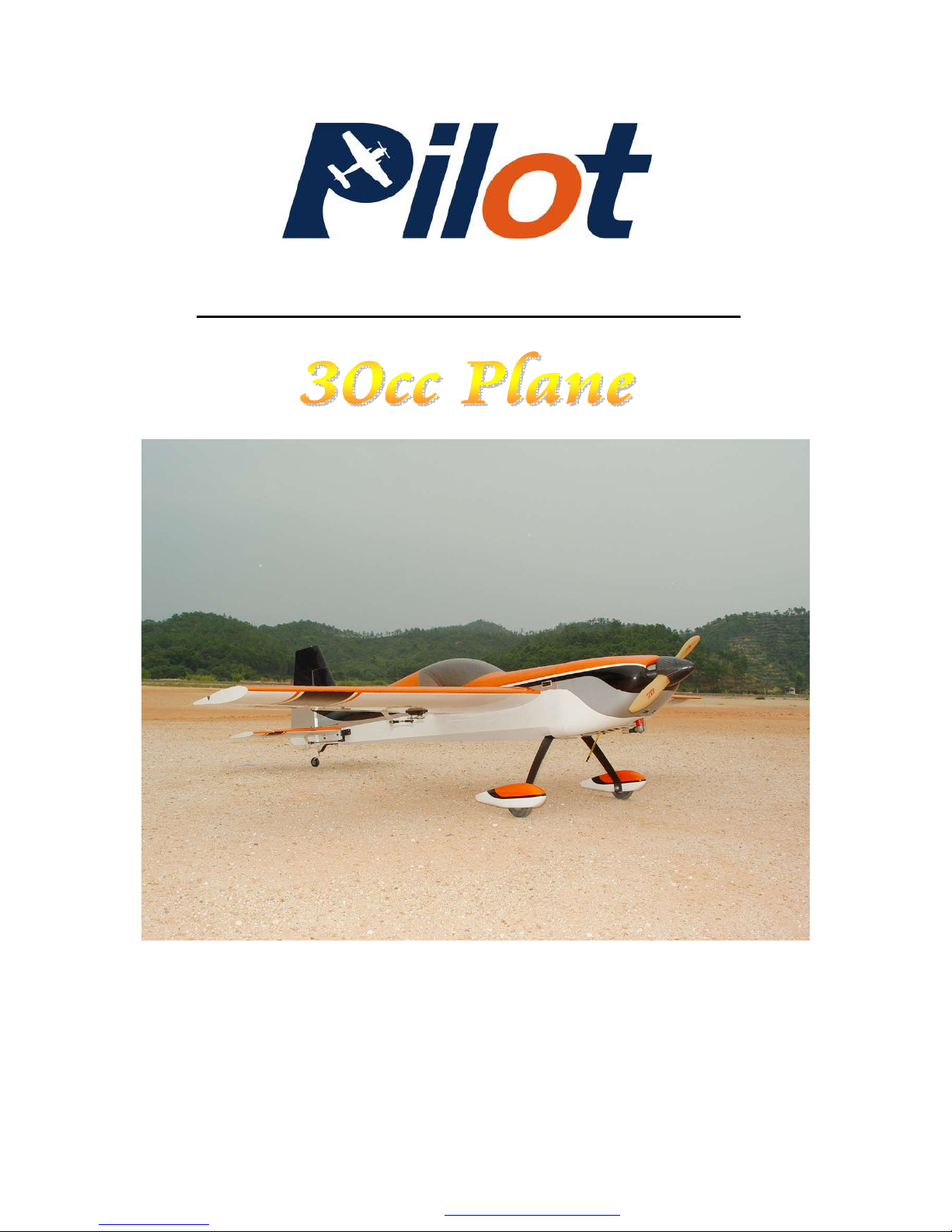
Wingspan: 88 in
Wingarea: 1479.8 sp in
Length: 78.8 in
Engine: 50CC
Assembly Manual For
PDF 文件使用 "pdfFactory Pro" 试用版本创建 www.fineprint.com.cn
Page 2
1
INTRODUCTION
Thank you for purchasing
our new 50cc Yak-54. we strive
to achieve the real Quick
Builded and ARF aircraf .
It just requires the least
amout of assembly of any kit
that almost finished in
factory.To obtain the perfect
performence,both the design
and manufacturing have been
taken care with the highest
quality from any
hardware,covering ,wood and
glue in the construction as
well.By optimal weight and
reliable construction,you will
find this plane is really ideal
for 3D -Freestyle and
aerobatic.
So we hope every effort and
service we offer will make you
feel easy and have a wonderful
time in the pleasure of flying in
3D space.
More information on website
www.pilot
www.pilot--
rc.com
rc.com
PDF 文件使用 "pdfFactory Pro" 试用版本创建 www.fineprint.com.cn
Page 3

2
W
W
ARRANTY
ARRANTY
■
All Pilot-RC products are guaranteed against
defects for 30 days of receiving your airplane. This
warranty is limited to construction or productions
defects in both material and workmanship , doesn't
cover any component parts damaged by use or
modification .
■
The manufacture can't supervise the assembly
,operation and maintenance ,and can't ensure your
radio system is in good condition. Therefore ,we are
not responsible for any damage occurring during
the use of a radio controlled model. It isimpossible
to determine for certain wehther crash damage was
the result of a radio systerm failure or pilot error even
improper installation of our products.Model airplane
owner is using it on his own responsibility.
■
In no event should Pilot-RC accept the liability
exceeds the original cost of the airframe (not include
engine and radio system).
■
No matter what reason you wish to return this
airplane , all shipping cost will be paid by costumer.If
some parts require replacement from us ,the original
parts’ return is at costumer' expense.
PDF 文件使用 "pdfFactory Pro" 试用版本创建 ÿ www.fineprint.com.cn
Page 4
3
ATTENTION
ATTENTION
■
You should not regard this plane as toy!
■
To ensure safety,please read the instruction
manual thoroughly before assembly .
■
Building and operating model plane require
diligent practicing and correct guidance. Any
neglect,carelessness and missing experience can
cause serious bodily harm and property damage.
■
Seek the assistant of a experienced person or
airplane model clubs in assembly ,operation and
maintenance to ensure quick and successful learning
■
Fly only in proven model airfield
that AMA
(Academy of Model Areonautics) approved
Pilot-RC has the right to change to this plane
,instruction and limited warranty without notice.
If you have any problems and questions ,please
contact pilot –RC
Email: [email protected] , [email protected]
Cellphone:+86 760 88781293
FAX: +86 760 88780293
Address: No.34,ChengnanErRoad , Zhongshan city, 528400, Guangdong
Province, China
PDF 文件使用 "pdfFactory Pro" 试用版本创建 餀 www.fineprint.com.cn
Page 5
4
Introduction ………………….………..….…….….
Warranty …………………….……..….…..…….
Attention …………….…………..….……..…….
Landing Gear And Rudder Unit
Rudder Assembly
Rudder Control Horns ………..…….…...……..
Tail Wheel Installation …………..……..........
Landing Gear Assembly .
Main Landing Gear Installation ………….…..…….
Pants Installation …………..….………
Servo Unit
Wing Servo Assembly
Servo Arm Installation ………….….……….
Aileron Control Horns ………….……….…..
Servo Installation …….…………..……
Rudder Servo Assembly
Servo Tray Installation ….…….….......……..
Servo Installation ……….….……...……
Elevator Servo Assembly
Servo Arm Installation ………….…………….
Elevator Control Horns ……………....….……
Servo Installation ……………….....………
Switch Assembly ………….……….....………
Engine Unit
Engine Assembly ……….…..……..……
Throttle Servo Assembly ….….…...…….……
Ignition Module ………….…….……….
Hatch And Fule Tank ………….….……....……
Crowl Assembly …………………......……
CG And Control Throws …………………………..
Flight Preperation …...…………….….…..……
INDEX
1
2
3
17
18
5
7
9
11
12
13
14
21
22
23
26
27
29
28
30
31
33
34
PDF 文件使用 "pdfFactory Pro" 试用版本创建 www.fineprint.com.cn
Page 6
5
Landing Gear and Rudder Unit
Rudder Assemby
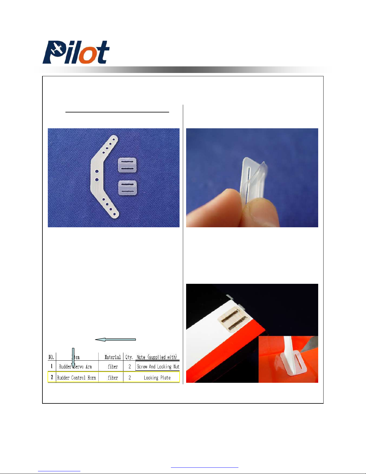
Rudder Control Horn
1. Tear off the cover on the horns
and locking plates
Please refer to the
HARDWARE LIST
(download with instruction)
to get the exact information
about every step. A printed
list is recommended for
your checking rapidly in
whole assembly
2. Trace around the locking plate
with kinfe and cut off the cover
below.Then the pre-cut slots appear
Example:
On the step of Rudder Control Horn installation
You can search
Rudder
PDF 文件使用 "pdfFactory Pro" 试用版本创建 ã www.fineprint.com.cn
Page 7
6
Rudder Assembly
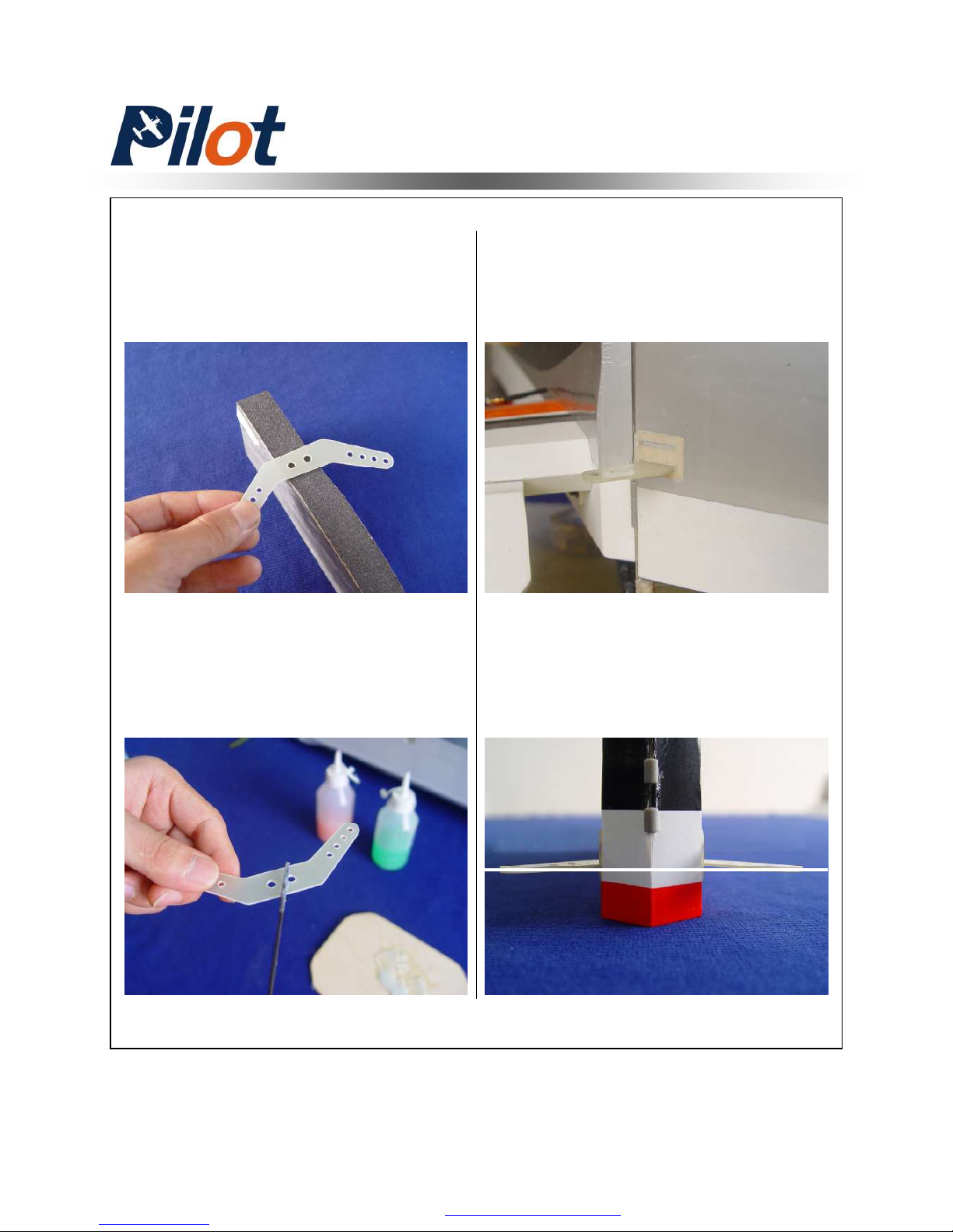
3. Scuff the middle of horns with a
piece of sand paper for good glue
bond.Then clean up the surface
4. Apply the 30 minutes epoxy
inside the pre-cut slot, and coat the
horn with epoxy as shown
6. Make sure the horn line up with
ground and align the both side
before epoxy has cured
5. Slid the horn into slot slightly
Mount the locking plates in
place.Wipe away excess glue with
rubbing alcohol
PDF 文件使用 "pdfFactory Pro" 试用版本创建 www.fineprint.com.cn
Page 8
7
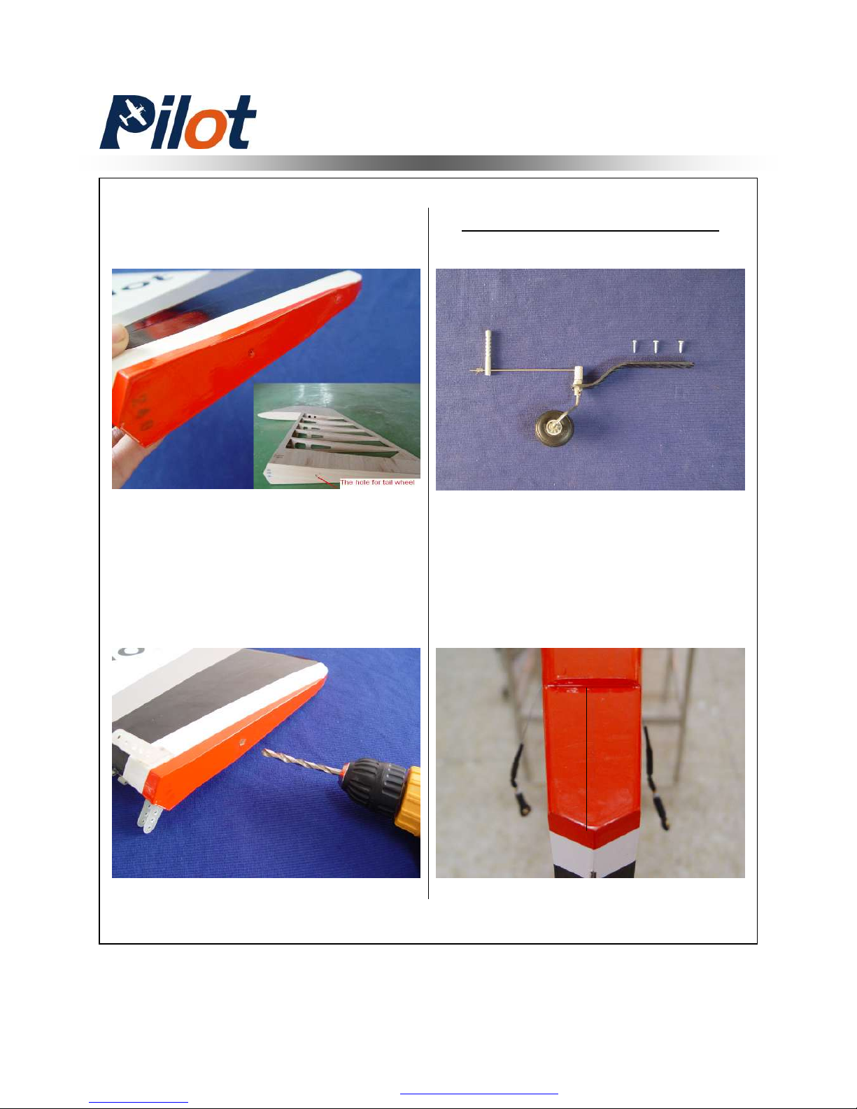
7. Note the pre-drill hole for tail
wheel under the cover.
8. Try fit the tail wheel subassembly
and drill hole with 6mm bit .But do
not mount the rudder steering tube
until finish tail wheel installation
Tail Wheel Installation
Rudder Assembly
1. Draw a center line with a pencil
as shown
PDF 文件使用 "pdfFactory Pro" 试用版本创建 www.fineprint.com.cn
Page 9
8
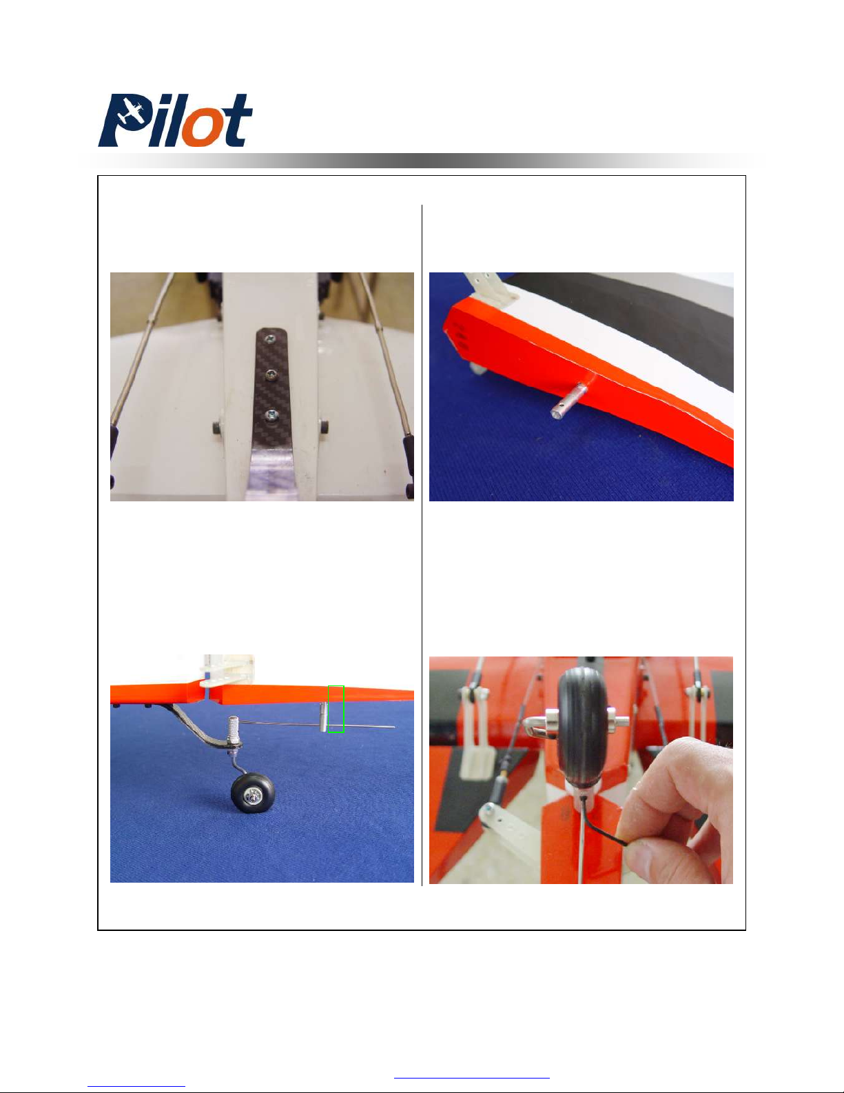
2. Mount self-tapping screws on the
tail wheel mounting block with the
bracket taped on place
3. Insert steering arm into rudder
steering tube and ensure the proper
depth
Rudder Assembly
4. Epoxy the steering tube in place
5. Tighten the set nut as shown
PDF 文件使用 "pdfFactory Pro" 试用版本创建 www.fineprint.com.cn
Page 10
9
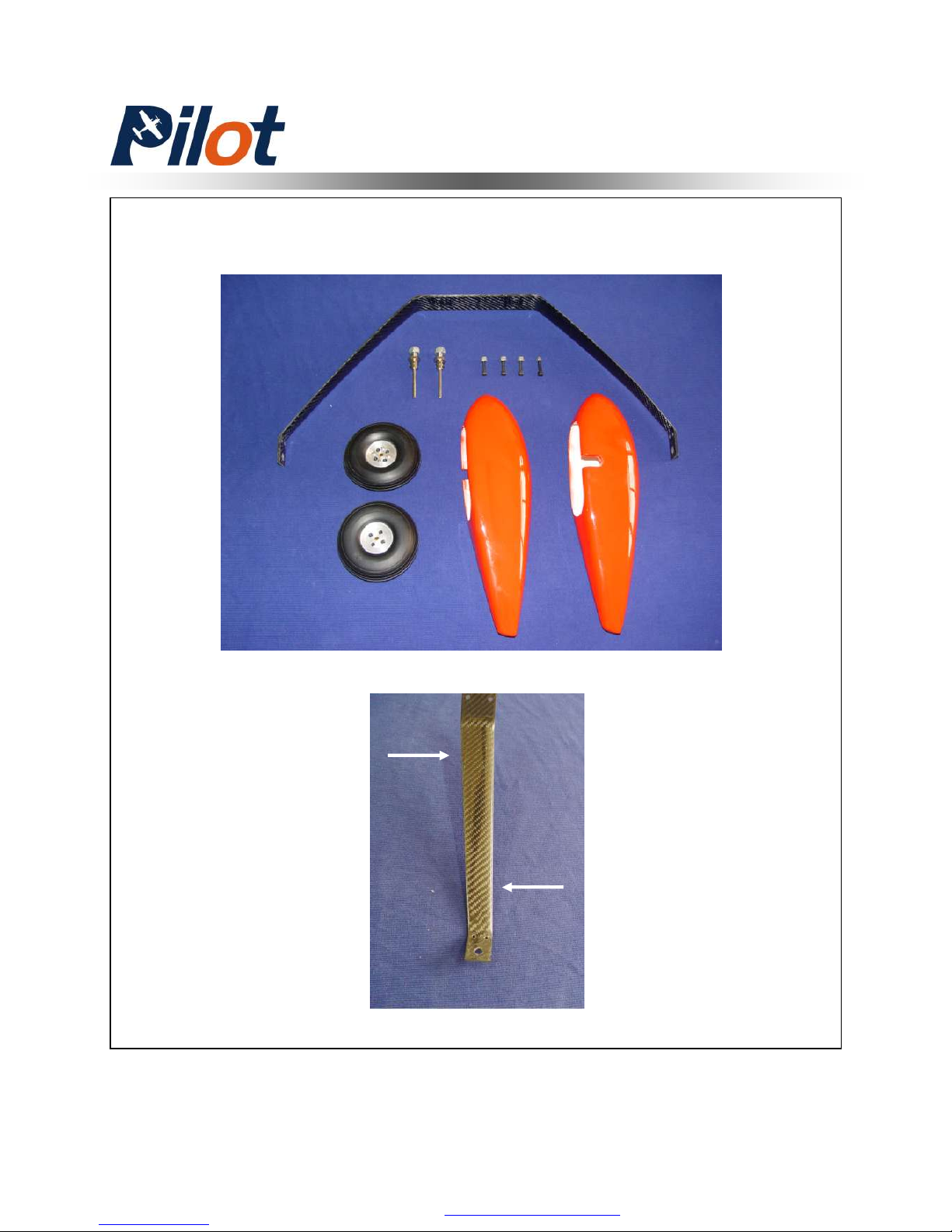
Main Landing Gear Installation
Landing Gear Assembly
NOTE: the correct edge in mounting
Taper
to rear
Straight
edge to
front of
fuse
PDF 文件使用 "pdfFactory Pro" 试用版本创建 ÿ www.fineprint.com.cn
Page 11
10
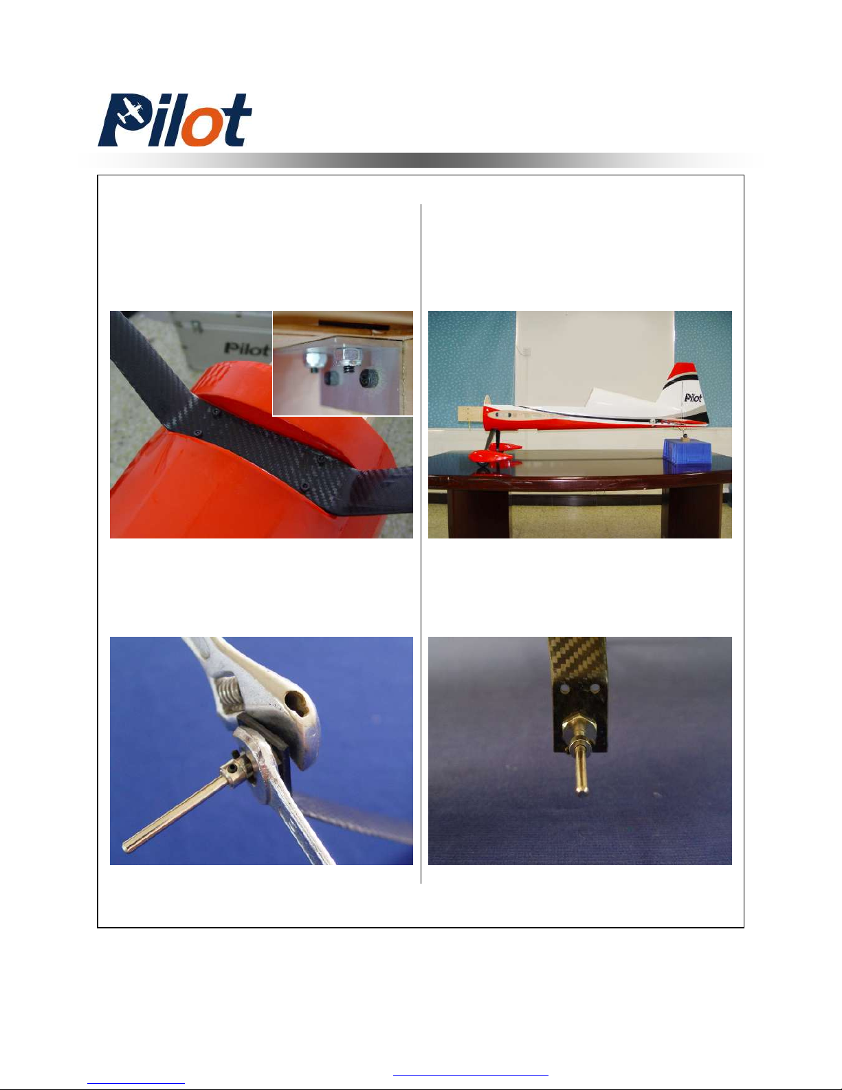
Landing Gear Assembly
1. Install the landing gear with the
bolts and locking nuts
Note:Don’t over tighten and crack
the carbon fiber
2. Install the landing gear axles with
lock nut ,but do not tighten
4. Make the flat sides of the axle bolt
vertical with ground .Then tighten the
lock nut against the landing gear strut
3. Lift the rear of fuse to line it up with
ground as shown
PDF 文件使用 "pdfFactory Pro" 试用版本创建 www.fineprint.com.cn
Page 12
11
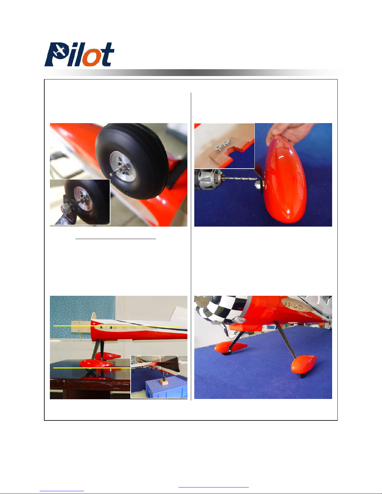
Landing Gear Assembly
1. Lift the rear of fuse and line the
wheel pant up with the ground by
slipping them over the axles and
supporting them from the rear for the
proper clearance
2. Drill the holes for the mounting
bolts and install the blind nuts.
3. Finish the wheel pants mounting
with the bolts and use Blue Loctite
on the threads
5. Install the collars and wheel in
order with a drop of Blue Loctite on
the collar set screw and ensure the
wheel is free to rotate.
Pants Installation
PDF 文件使用 "pdfFactory Pro" 试用版本创建 www.fineprint.com.cn
Page 13
12
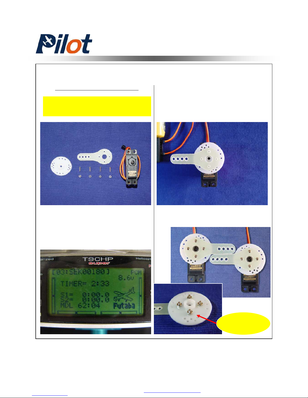
Servo Unit
Wing Servo Assembly
Minimum Request Servo:
Servo Arm Installation
1. Turn on your transmitter and
plug the servo into receiver. Ensure
every channel is neutral
2. Ensure the servo arm is 90
degrees with servo as shown. Then
mark and drill holes with 2mm bit
3. Mounting screws and nuts
180 in.zo / Metal Gear / Digital
A drop of fast
cured gule here
PDF 文件使用 "pdfFactory Pro" 试用版本创建 ÿ www.fineprint.com.cn
Page 14
13
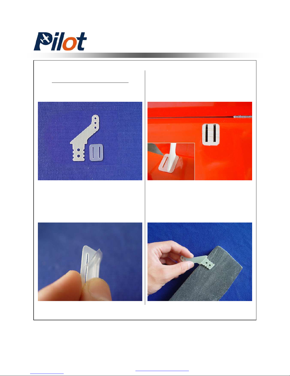
Aileron Control Horns
1. Tear off the cover on the horns
and locking plates
2. Trace around the locking plate
with kinfe and cut off the cover
below.Then the pre-cut slots appear
3. Scuff the horns with a piece of
sand paper for good glue bond.Then
clean up the surface
Wing Servo Assembly
PDF 文件使用 "pdfFactory Pro" 试用版本创建 www.fineprint.com.cn
Page 15
14
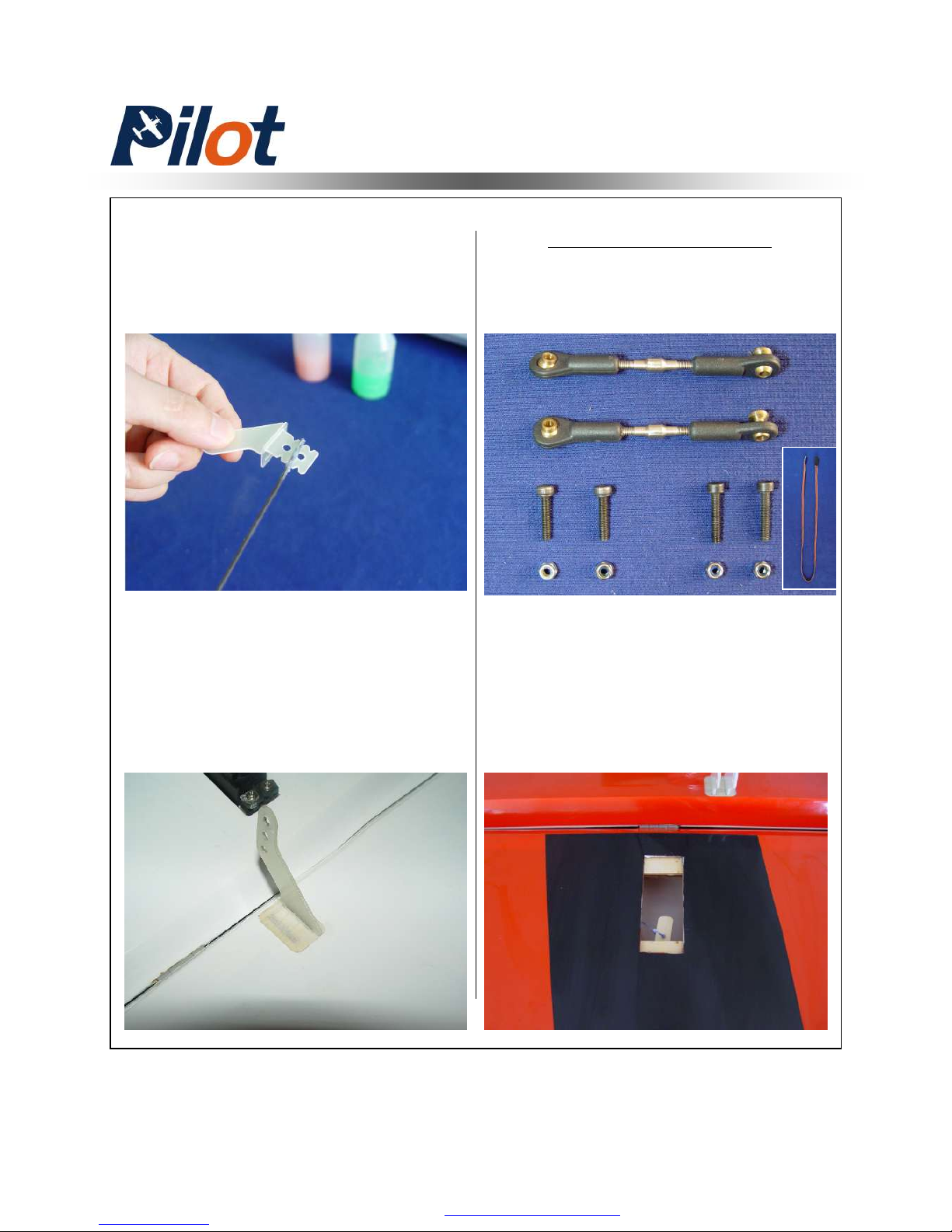
4. Apply the 30 minutes epoxy
inside the pre-cut slot for horn ,and
coat the horn with epoxy as shown
5. Slide the horn into slot slightly
and Mount the locking plate in
place.Wipe away excess epoxy
with rubbing alcohol
Servo Installation
1. Cut out the cover for servo location
carefully as shown
Wing Servo Assembly
PDF 文件使用 "pdfFactory Pro" 试用版本创建 www.fineprint.com.cn
Page 16
15
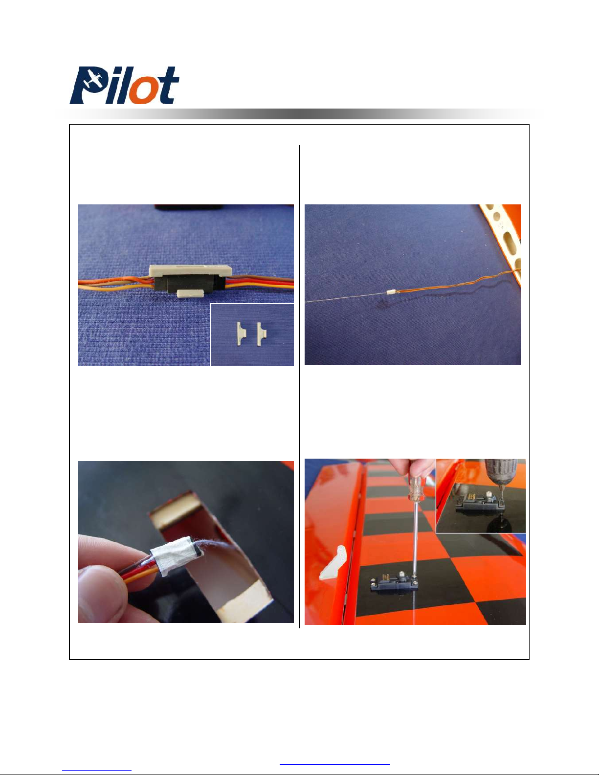
3. Tape the lead to pull-string
tightly. In order to ensure the servo
wire can be pulled out without
hanging up inside wing
4. Then put the extention lead
through the root of wing
5. Install servo with mounting
screws. Face the brand toward the
trailing edge of the wing. Use 1mm
bit to drill the mounting holes
Wing Servo Assembly
2. Lock the connector with the
provided safety clip against vibration
and loosened tension as shown
PDF 文件使用 "pdfFactory Pro" 试用版本创建 www.fineprint.com.cn
Page 17
16
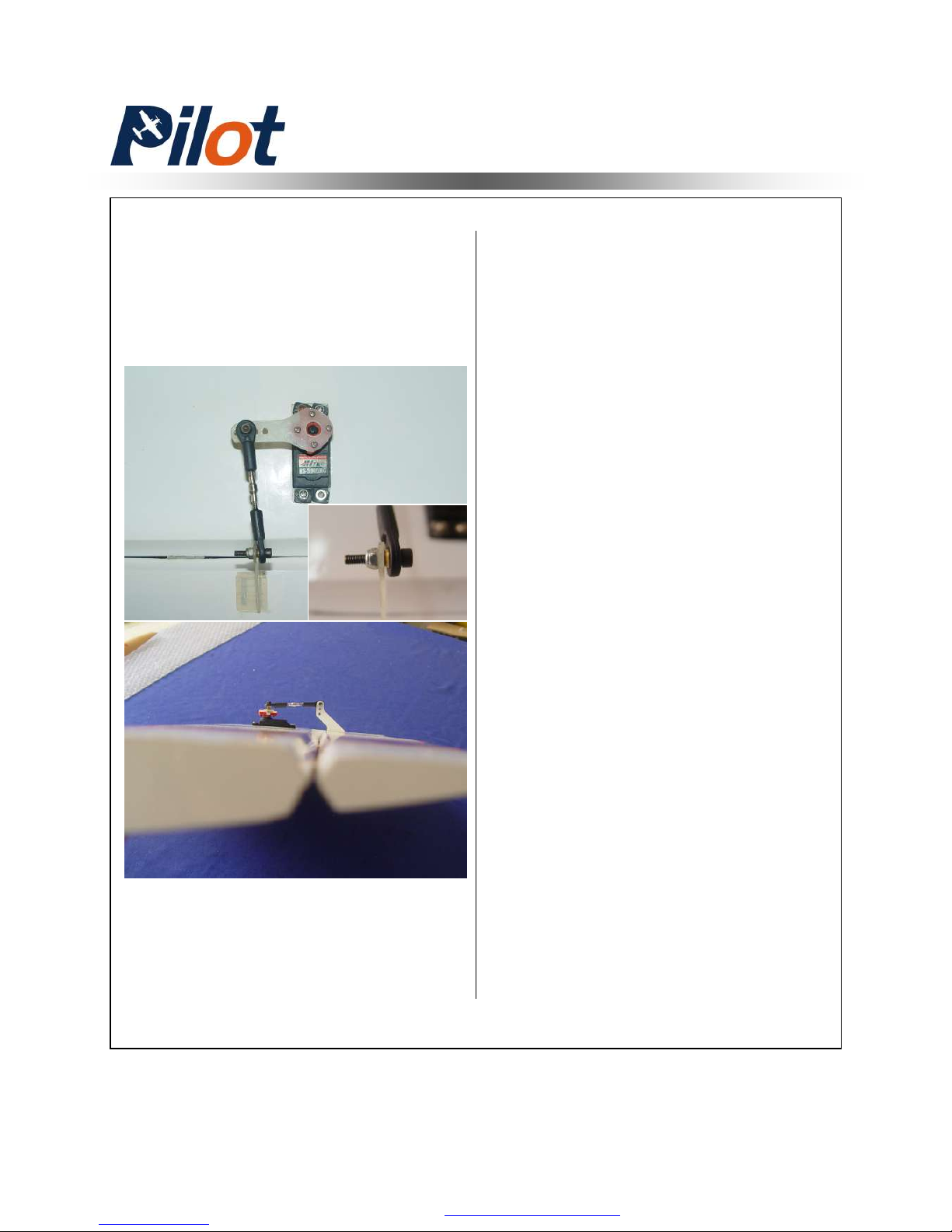
6. Install the servo arms facing
toward the wing tip and adjust
pushrod in proper length to keep the
aileron panel on the neutral position
7. Repeat all the step above for the
other wing
The carbon tube and wing bolts use
to be mounted in the final assembly
Wing Servo Assembly
PDF 文件使用 "pdfFactory Pro" 试用版本创建 www.fineprint.com.cn
Page 18
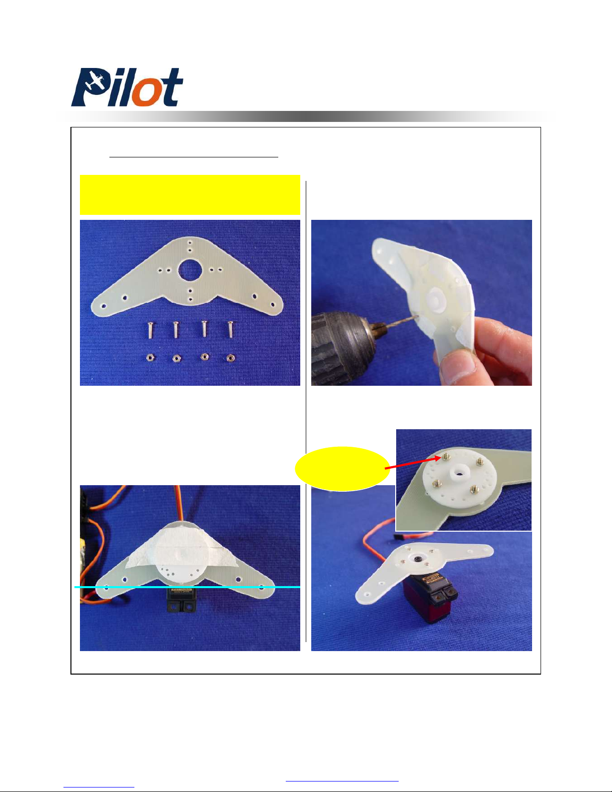
17
Rudder Servo Assembly
Servo Tray Installation
1.Turn on your radio device according
the Wing Servo Installation.Keep the
servo holes on center and the arm
aligned with servo as shown. Then tape
tightly
2. Drill holes with 2mm bit
A drop of fast
cured gule here
3. Mounting screws and nuts
Minimum Request Servo:
180 in.zo / Metal Gear / Digital
PDF 文件使用 "pdfFactory Pro" 试用版本创建 www.fineprint.com.cn
Page 19
18
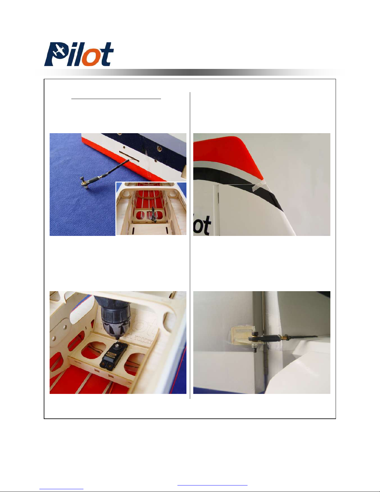
Servo Installation
1. Mount servo with mounting
screws and face the brand toward
the rudder.Drill holes with 1mm bit
2. Tape the rudder panel to top of
the vertical fin in the neutral position
to make it straight
The rudder cables and couplers have
been installed as shown
3. Attach the pre-installed boll link
to the rudder horn and not tighten
the locking nut
Rudder Servo Assembly
PDF 文件使用 "pdfFactory Pro" 试用版本创建 www.fineprint.com.cn
Page 20
19
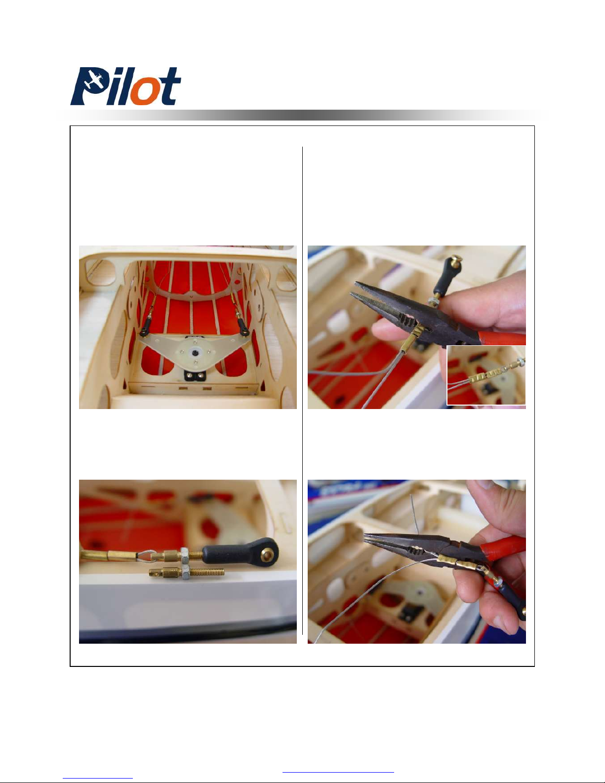
4. Turn on your radio to keep the
servo neutral. Mount the pre-installed
boll link to the rudder arm without
locking nut. Put two brass tube
through the cable and thread through
the coupler hole. Ensure the cables
are straight
NOTICE: The coupler is best to
thread half way into ball link for
further tightening next
5. Crimp them in place with crimping
pliers
6. Cut away excess cable
Rudder Servo Assembly
PDF 文件使用 "pdfFactory Pro" 试用版本创建 www.fineprint.com.cn
Page 21
20
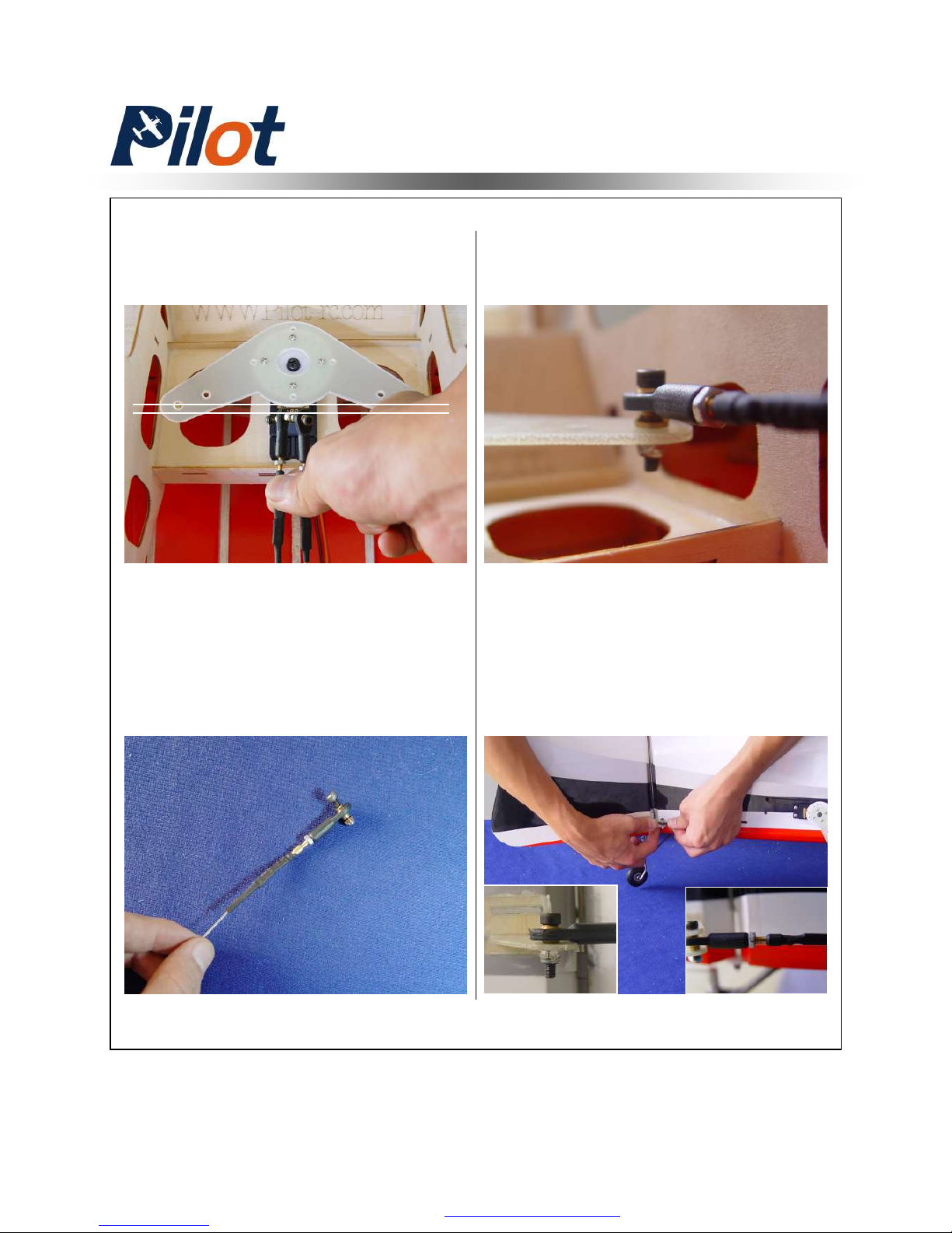
7. Thread the coupler in 2 – 4 mm.
Ensure the same length of cables
and tension
9. Remove the ball links from
rudder horn and install the servo
arm ball links with bolts and nuts
10. Turn off the radio now. Reinstall
the ball link (Don’t pull strongly to
hurt the rudder or back to step 7 for
readjustment )you can find a helper
and do that at certain deflection with
supporting the bottom of the rudder.
Rudder Servo Assembly
8. Shrink the heat shrinking tube on
the brass tube
PDF 文件使用 "pdfFactory Pro" 试用版本创建 www.fineprint.com.cn
Page 22

21
Elevator Servo Assembly
Minimum Request Servo:
1. Turn on your transmitter and
plug the servo into receiver. Ensure
every channel is neutral
2. Ensure the servo arm is 90
degrees with servo as shown. Then
mark and drill holes with 2mm bit
3. Mounting screws and nuts
180 in.zo / Metal Gear / Digital
A drop of fast dry
gule here
Servo Arm Installation
PDF 文件使用 "pdfFactory Pro" 试用版本创建 ÿ www.fineprint.com.cn
Page 23
22
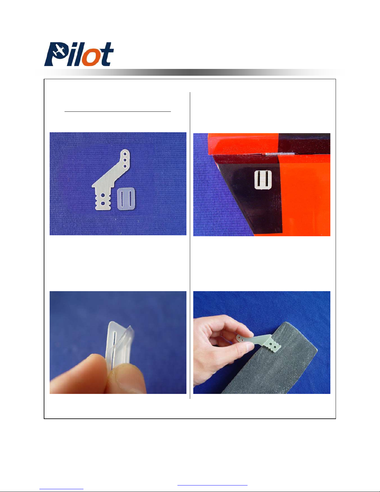
Elevator Control Horns
1. Tear off the cover on the horns
and locking plates
2. Trace around the locking plate
with kinfe and cut off the cover
below.Then the pre-cut slots appear
3. Scuff the horns with a piece of
sand paper for good glue bond.Then
clean up the surface
Elevator Servo Assembly
PDF 文件使用 "pdfFactory Pro" 试用版本创建 www.fineprint.com.cn
Page 24
23
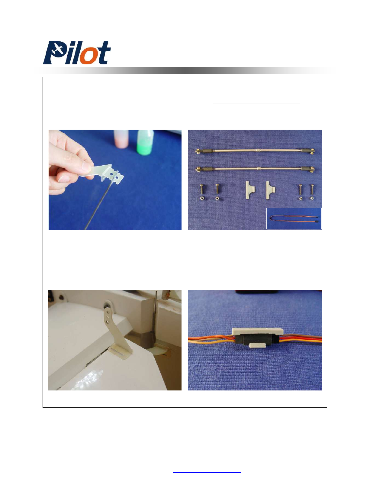
4. Apply the 30 minutes epoxy
inside the pre-cut slot for horn ,and
coat the horn with epoxy as shown
Servo Installation
Elevator Servo Assembly
1. Lock the connector with the
provided safety clip against vibration
and loosened tension as shown
5. Slide the horn into slot slightly
and Mount the locking plate in
place.Wipe away excess epoxy
with rubbing alcohol
PDF 文件使用 "pdfFactory Pro" 试用版本创建 www.fineprint.com.cn
Page 25
24
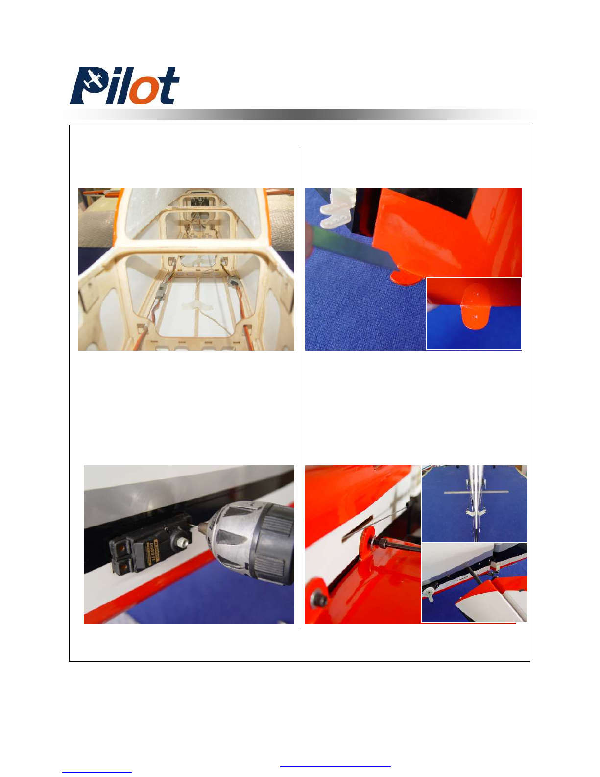
3. Install servos with mounting
screws. Face the brand toward the
rear of fuse. Use 1mm bit to drill the
mounting holes
2. Then put the extention lead
through fuselarge
4. Cut the cover on the pre-drill hole
for stab mounting
5. Install the stab with mounting
bolts and washers
Elevator Servo Assembly
PDF 文件使用 "pdfFactory Pro" 试用版本创建 www.fineprint.com.cn
Page 26
25
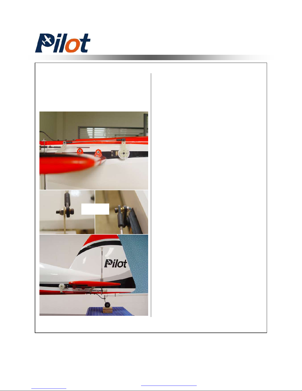
6. Install the servo arms facing
toward the ground and adjust
pushrod in proper length to keep the
aileron panel on the neutral position
as shown
7. Repeat all the step above for the
other stabilizer
Elevator Servo Assembly
NOTICE
PDF 文件使用 "pdfFactory Pro" 试用版本创建 ÿ www.fineprint.com.cn
Page 27
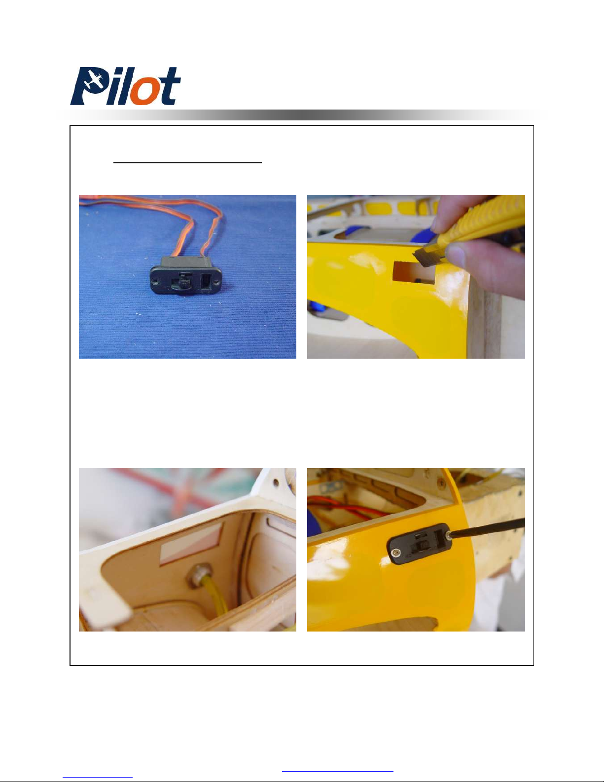
26
Switch Installation
Switch Assembly
Note: The switch mounting holes
have been pre-cut for standar size.
Otherwise fill it with the same size
1.7mm plywood and a larger one
(both not included) as reinforce
2. Finish the mounting with screws
and nuts supplied.
1.cut off the cover with a sharp knife
PDF 文件使用 "pdfFactory Pro" 试用版本创建 www.fineprint.com.cn
Page 28
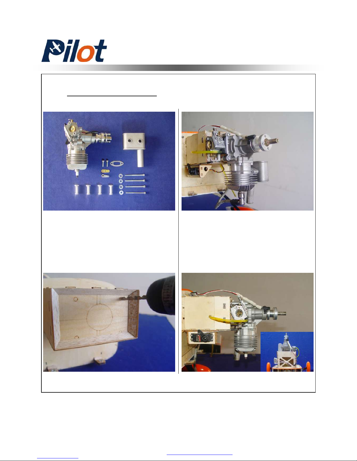
27
Engine Installation
Remenber: Use Bue Loctite on all
engine mounting screws
Engine Assembly
The firewall has been mounted.
Drill according pre-set laser holes
for DLE-30. Otherwise measure
your engine’s mounting location.
PDF 文件使用 "pdfFactory Pro" 试用版本创建 www.fineprint.com.cn
Page 29
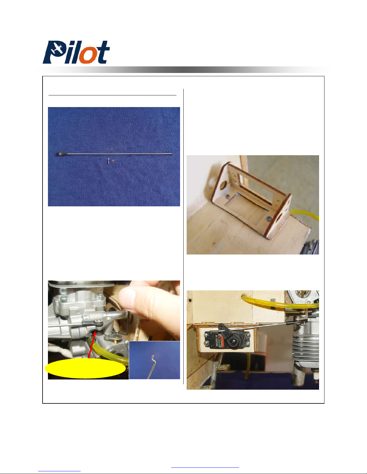
28
Throttle servo Installation
A drop of gule on nut
5. Finish the servo installation with
mounting screws
Throttle Servo Installation
1. Install the engine throttle arm
witn a little Blue Loctite. Measure
and cut the extra wire .Then bend
to a sharp of “z” as shown. Mount
the throttle pushrod to engine
2. Determine where the throttle servo
mounting tray is going to be mounted
on the engine box to get the straight
and precise throttle linkage connection.
Then make a mark and epoxy the tray
in place .Finally secure with selftapping screws
PDF 文件使用 "pdfFactory Pro" 试用版本创建 www.fineprint.com.cn
Page 30
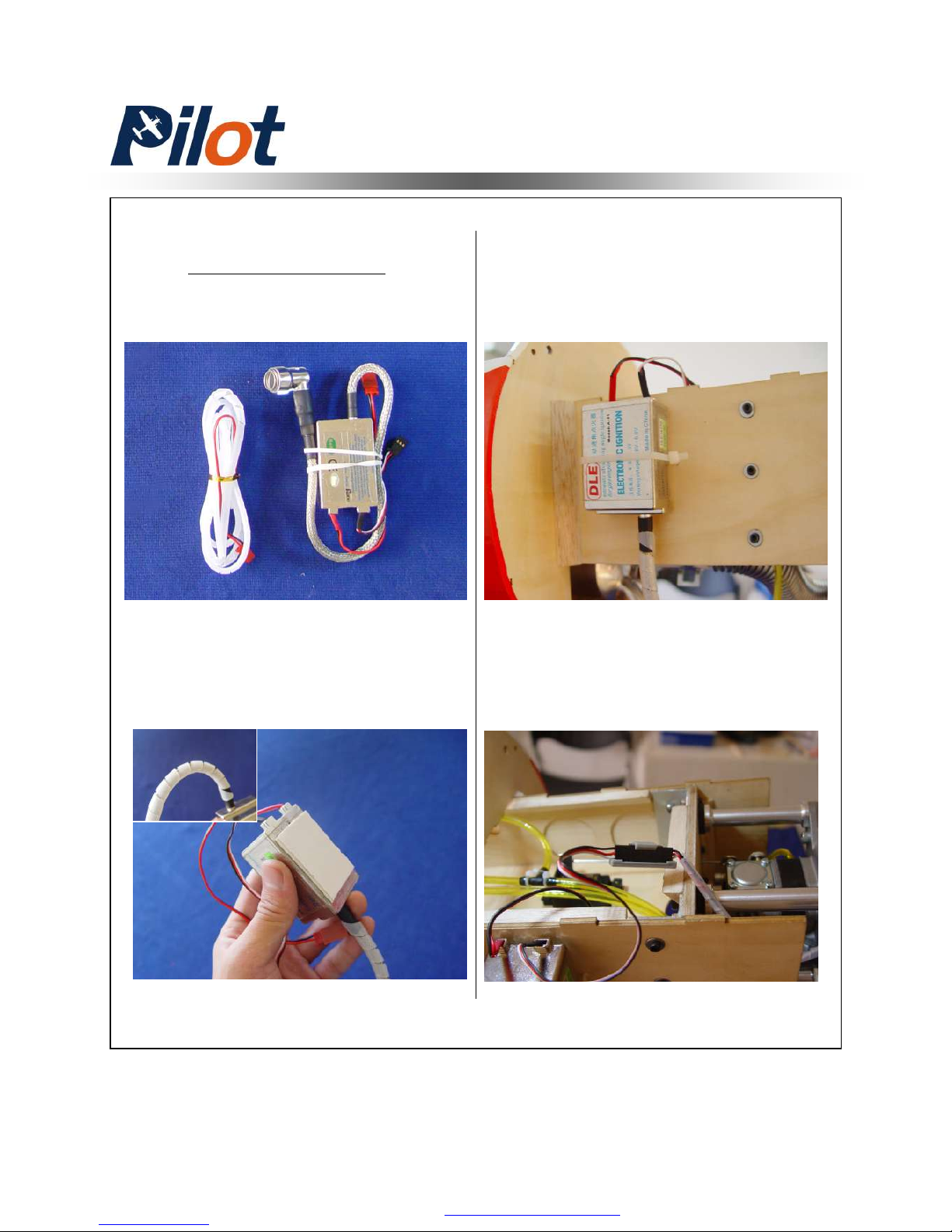
29
Ignition Module
Ignition Module
1. Tape foam rubber on bottom of
ignition and attach to safety cover
surplied as shown
2. Position the ignition outside the
engine box to allow the spark plug
leads to connect the engine without
excess tension .Drill for Nylon tie
3. Lock the connectors with the
provided safety clip against vibration
and loosened tension as shown
PDF 文件使用 "pdfFactory Pro" 试用版本创建 www.fineprint.com.cn
Page 31
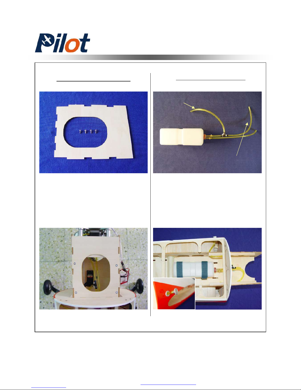
30
Engine Box Hatch
Epoxy the hatch in place and secure
with self-tapping screws
Fule Tank And Dot
Fule tank and fule dot have been
installed.Just tighten the velcro ties
Hatch And Fule Tank
Fule line
Fule Fill Line
PDF 文件使用 "pdfFactory Pro" 试用版本创建 ÿ www.fineprint.com.cn
Page 32
31
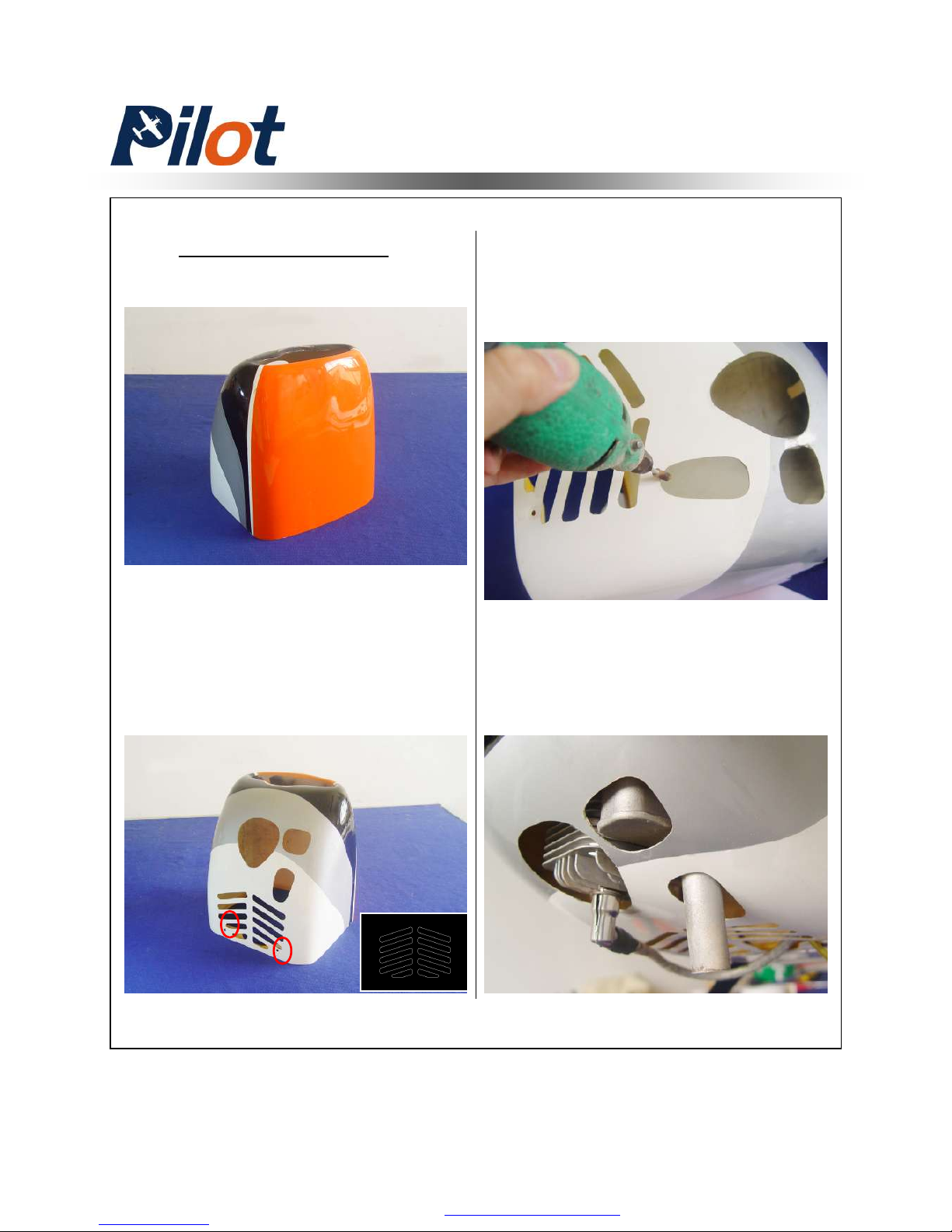
Crowl Assembly
Crowl Assembly
1. Make or use the supplied pattern
of the exit air cooling. But do not cut
off the crowl mounting holes position
as shown
3. Also cut out for clearance for the
exhaust pipes
2. Use a fiber cutting tool to rough
cut the cowl and finish with a round
sander.Trial fit to make sure there is
a minimum of 3/8”around the engine
cooling.
PDF 文件使用 "pdfFactory Pro" 试用版本创建 www.fineprint.com.cn
Page 33
32
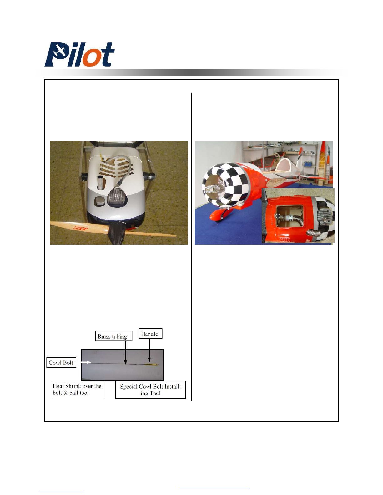
YAK-54 73’’ have two that mount
from the rear of the firewall on the
top of the cowl and two that mount
from the front of the cowl opening
4. Ensue all the corner are rounded
and not sharp 90 degrees against
splitting under vibration. Trial fit till
the cowl is right
Maybe more exit air cooling
will be needed to allow for
depending on your engine’s
recommended running
temperature.Always check
your engine and Pilot-rc
dosen’t accept responsibility
for any damage from
improper engine cooling
NOTICE:
YAK-54 73’’ need an extension tool
with a proper size ball driver and
handle by cutting standard ball driver
in half .Some small heat shrink
tubing are attached to the ball driver
to hold in place.You have to reattach
the cowl in the future by this method
Crowl Assembly
PDF 文件使用 "pdfFactory Pro" 试用版本创建 www.fineprint.com.cn
Page 34
33
CG And Control Throws
■ Afer you set the given control
throws up and have a few flights under
you belt, you can change the amounts
as well as moving the CG back at 1/4"
intervals
Elevator: 40 Degrees on High rate
12 Degrees on Low rate
Aileron: 30 Degrees on High rate
12 Degrees on Low rate
Rudder: 45 Degrees on High rate
40 Degrees on Low rate
Throttle: Adjust idle –full
■ Learn to use exponential of about
40 percent on your elevator to make
great landings and not over control a
highly aerobatic airplane.Use 70
percent exponential on High Rate!
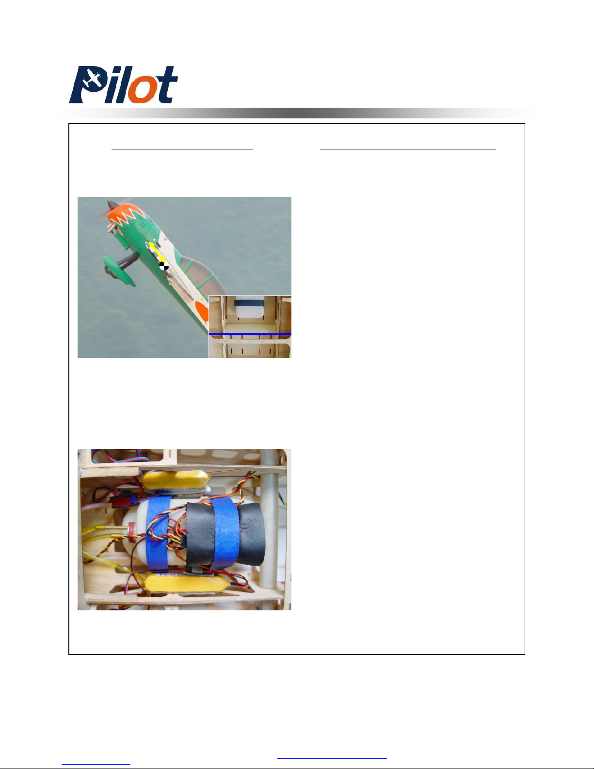
The First Flight set upCenter Of Gravity
The center of gravity is on the
rear of the wing tube as shown
Your balance at the CG will
determine batteries final mounting
location .Mount batteries and
secure with Nylon ties
PDF 文件使用 "pdfFactory Pro" 试用版本创建 www.fineprint.com.cn
Page 35
34
■ Make sure you have the right model programmed into your
transmitter
■ Check the direction of each surface not and also right before
you take off .
■ Rememver nothing wrong on the ground ever improves in
the air
■ Check the air plane with the engine running and do a range
check with
■ your body between you and the plane at 150 feet.
■ Check your battery voltage after each flight in case one
servo is draining your battery
■ Recheck all screws ,horns and linkages for slop after your
maiden fight and check for damage if you made a bad landing
you first time
■ Have an experienced pilot fly it for you the first time if you
have any doubts in your mind about the maiden flight
■ Take a break after you first flight and let the adrenaline
burned off by bragging to your fellow menbers how good it
flies
■ Fly low and at a medium speed on your first few flight
■ Listen to your engine run and have an observer with you to
remember what you talked about during the flight or if you ger
into trouble . Always balance your props, vibration is a killer.
■ Remember nose heavy airplanes fly all the time, tail heavy
airplanes fly only once.Be on the CG!
■ Fly 3D two mistakes high in the beginning and not close to
people, planes or runways. Being a center of the runway hog
does not endear you to many modelers.
Flight Preperation
PDF 文件使用 "pdfFactory Pro" 试用版本创建 www.fineprint.com.cn
 Loading...