

Page 1
INSTRUCTION MANUAL
Page 1
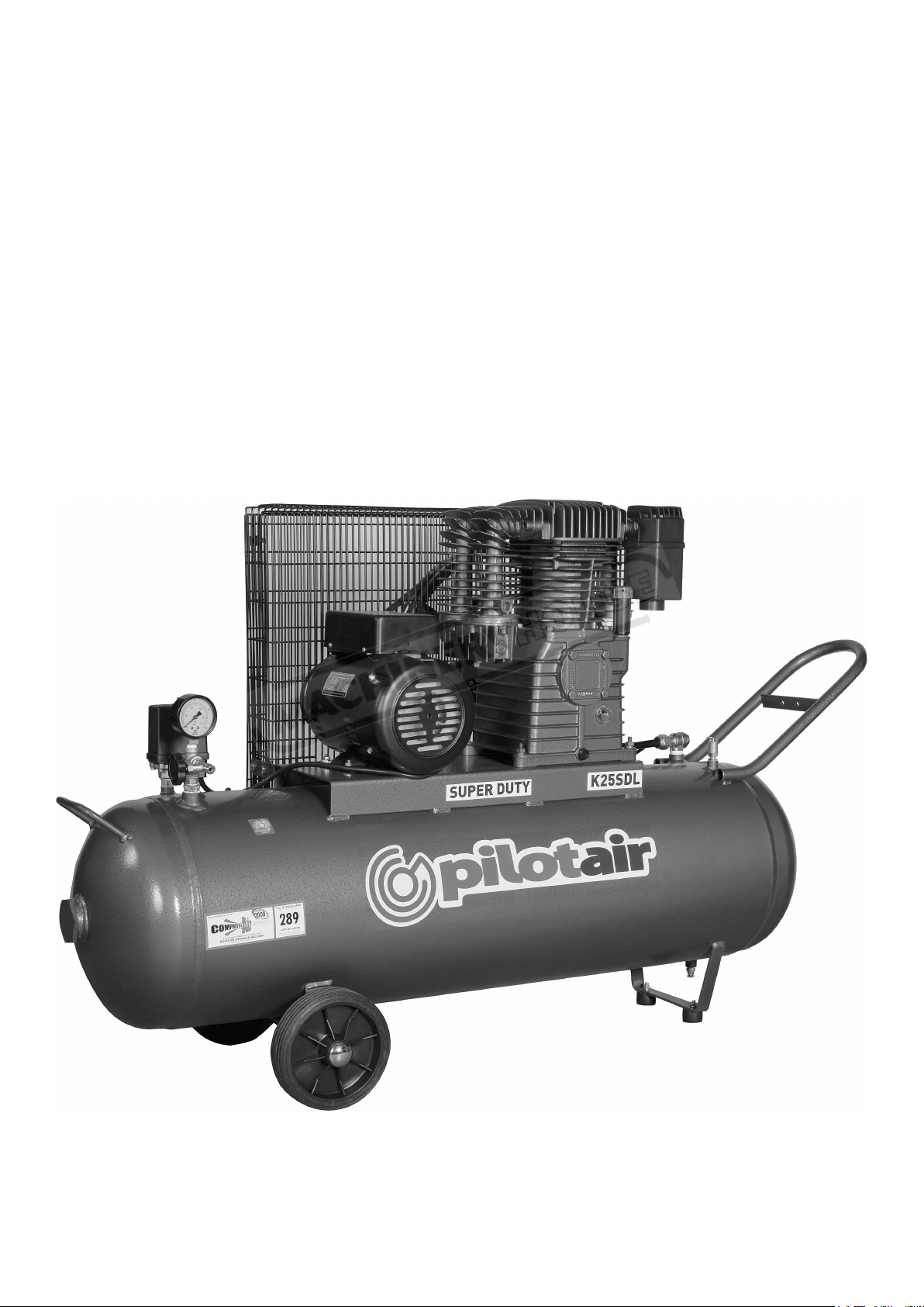
Instruction Manual for K25SDL (C511)
19/12/2014
K25SDL
Heavy Duty Air Compressor (240V)
100 litres / 3hp
13.1 Displacement
C511
Page 2
RELIABILITY IN AIR POWER
Page 2
Instruction Manual for K25SDL (C511)
19/12/2014
NSW:
115 Beaconsfield Street
Silverwater NSW 2128
PH : (02) 9648 3099
FAX :(02) 9648 3362
QLD:
Unit 11, 97 Jijaws St.,
Sumner Park QLD 4074
PH : (07) 3279 1213
FAX :(07) 3279 1762
VIC:
PH : 1300 667 579
FAX :(02) 9648 3362
SA: (Statewide Agencies P/L)
7/400 Grand Junction Rd
Mansfield Park SA 5012
PH : 1300 667 579
FAX: (08) 8347 4660
WA: (Air & Power P/L)
7-9 Fisher St
Belmont WA 6904
PH : (08) 9479 4220
FAX :(08) 9277 4040
INSTRUCTION AND PARTS LIST
MODEL: K25
____________________________________________________________________________________________________
PILOT AIR COMPRESSORS: THE FIVE “S” ADVANTAGE
SUPERIOR PRODUCT, SPECIALISTS, SERIES, SUPPORT, SERVICE
www.pilotair.com.au
Page 3
USER GUIDE
Page 3
Instruction Manual for K25SDL (C511)
19/12/2014
Congratulations on the purchase of a PILOT air compressor. This unit has been designed to
provide reliable and trouble fee usage in servicing your compressed air requirements.
Please take a moment to familiarise yourself with the information contained in the following
sections of this guide before attempting to operate this unit.
LOCATION OF UNIT:
For optimum efficiency locate unit in a clean, dry and cool environment with good ventilation.
Avoid placing obstacles either on or around unit to facilitate maximum air flow and cooling.
OPERATION:
NOTE:
CHECK OIL LEVEL BEFORE USE IN CASE OF LOSSES
INCURRED DURING SHIPPING
A) ELECTRIC UNITS
Ensure ON/OFF switch is located on the pressure switch is in an ON/OFF position (down),
before inserting power plug into appropriate receptacle and applying power.
Unit can then be switched on using the ON/OFF switch. The pressure switch will
automatically start and stop the compressor when the air receiver drops below or reaches
factory set cut-in and cut-out pressures respectively.
NOTE:
ALWAYS SWITCH UNIT ON AND OFF VIA
PRESSURE SWITCH TO ENSURE THE UNIT
DOES NOT START AGAINST HIGH PRESSURE
IMPORTANT:
TO PREVENT DAMAGE TO UNIT OR PERSONS DO NOT
ATTEMPT TO MODIFY, BYPASS OR REMOVE PRESSURE
SWITCH OR SAFETY VALVE IN ANY WAY.
“TM” OR “K” SERIES ARE DESIGNED TO OPERATE TO
A MAXIMUM PRESSURE OF 10 BAR.
www.pilotair.com.au
Page 4
The air receiver is equipped with a safety valve to release pressure in the event of a pressure
Page 4
Instruction Manual for K25SDL (C511)
19/12/2014
switch cut-out failure. To prevent damage to the unit, do not attempt to modify, bypass or
remove the pressure switch or safety valve in anyway.
The motor features a manual overload protection (where fitted). In poor power conditions or
motor over temperature conditions, this overload protector will cut power to the motor. To
reset, wait for the motor to cool then press reset button. If problems persist, check for power
ratings, faulty power or poor connections.
B) PETROL/DIESEL DRIVEN
Please refer to OEM documentation in reference to care and operation of your petrol/diesel
engine.
This unit has been designed to “idle down” to minimum operating speeds when factory set cutout pressures are reached. This saves both fuel consumption and wear on moving parts. When
pressure drops to set cut-in pressures the unit will automatically resume pumping at normal
operating speeds.
To facilitate easy starting of the unit and to ensure no damage to the electric starter
(where fitted) always open the “EASY START” valve until the unit is operating and then
close for normal operation. This valve is located on the motor/pump platform (models
K25P,K30P) or in the discharge pipe from the pump to the air receiver (other models).
SAFETY
• Pressure vessels (air receivers) are a type of plant, and as such, MAY be required to be
registered with the relevant statutory authority in your state. Regulations regarding plant
registration vary from state to state. Check with your relevant government authority about
plant registration.
• Compressed air can be dangerous. Never point compressed air tools or equipment towards
another person.
• After use, drain all residual air pressure or engage outlet tap to prevent accidental
discharge by children.
• Keep clear of compressor pump during and after operation. Heat build up in the pump may
cause burns to unwary.
• Never operate the unit without factory fitted belt guard.(belt drive models) or pump shroud
(direct drive models).
• Never operate the unit with damaged or exposed electrical wiring.
• Do not alter, adjust or remove any components on the unit without technical support.
• Whenever transporting an air compressor, ensure all air is drained from the air receiver.
There should be NO residual air pressure in the air receiver.
www.pilotair.com.au
Page 5
MAINTENANCE INSTRUCTIONS
Page 5
Instruction Manual for K25SDL (C511)
19/12/2014
• Check that fuses or circuit breakers correspond to motor rating. In case of 415-Volt units, check
rotation as indicated by arrow attached to unit. On 240-Volt units, avoid using extension leads as
they could cause voltage drop and power loss to motor. If extension is to be used, please follow the
table below.
TABLE 1.
KW HP VOLTS RECOMMENDED WIRE SIZE
1.65 2.25 240 HEAVY DUTY, 1.5MM SQUARE WIRE (MAX LENGTH 20 M)
2.20 3.00 240 HEAVY DUTY, 1.5MM SQUARE WIRE (MAX LENGTH 10 M)
• Oil level must be obtained at centre of oil sight glass. Do not overfill as this could cause excessive
oil out going from the crank case breather.
• Oil is to be replaced every 1000 working hours or on a six (6) monthly basis.
RECOMMENDED OIL:
• PILOT PCO-40G or equivalent (Stationary models).
• PILOT PCO-30G or equivalent (Portable models).
Note: In humid and/or very low duty cycle environments, condensate may collect in the
sump. Under these conditions, it is a requirement that the operator drain the residual
water from the sump on a regular basis and/or change the oil more frequently than
recommended above.
• Air filter element should be cleaned periodically and replaced every 500 working hours. (Under
normal environmental conditions).
• Routine maintenance should be performed on at least a six (6) monthly basis.
• Condensation must be drained from air receiver at least weekly.
• Unit must be kept clean to allow proper cooling to take effect. Special care should be taken to
clean the crankcase breather in order to allow proper crankcase breathing.
• Whenever attempting to carry out any maintenance to compressors, isolate power and release all
pressure from receiver.
• For information regarding spare parts and/or service, please always quote model and serial
number.
• PLEASE KEEP THIS INFORMATION NEAR MACHINE, SO IT CAN BE READ BY
ANYONE ATTEMPTING PREVENTATIVE MAINTENANCE.
www.pilotair.com.au
Page 6
NOTE:
Page 6
Instruction Manual for K25SDL (C511)
19/12/2014
DO NOT BOLT COMPRESSOR DIRECTLY ONTO FLOOR. THIS MAY
CAUSE CRACKS IN THE AIR RECEIVER. PLACE COMPRESSOR ON
THE RUBBER VIBRATION PADS PROVIDED. IF THE COMPRESSOR
MUST BE BOLTED, ENSURE RUBBER VIBRATION PADS ARE IN PLACE
AND FASTEN, LEAVING A GAP BETWEEN BOLT HEAD OR NUT AND
COMPRESSOR FOOT TO AVOID ANY METAL TO METAL CONTACT.
COMPRESSOR COMPONENT DESCRIPTIONS
• PRESSURE SWITCH: This switch is located on the top of the air receiver and functions as a
manual on/off switch in addition to automatically stopping and starting the compressor at factory
pre-set pressures (electric models only).
• PRESSURE GAUGE: The Pressure Gauge is located on the air receiver and indicates the
pressure held in both PSI and KPA.
• SAFETY VALVE: The Safety Valve is located on the air receiver and is designed to release
pressure in the event of a pressure switch failure.
• OVERLOAD PROTECTION: Electric models are fitted with an overload protector, to protect
the motor in the event of an over temperature condition. These reset buttons are located either on
the pressure switch or the motor itself.
• CHECK VALVE: The Check Valve is located at the junction of the pump discharge pipe and the
air receiver. The check valve prevents air pressure form returning from the air receiver to the
pump.
• EASY START VALVE: (Petrol/Diesel models only) The Easy Start Valve is located on the check
valve for portable units and on the compressor platform for stationary units. This valve should be
opened for ease of starting of the engine and closed when running for normal operation.
• RECEIVER DRAIN: The Receiver Drain is located at the underside of the air receiver and is
used for draining condensate from the receiver.
• OIL SIGHT GLASS: The Oil Sight Glass is located on the side of the compressor pump
(opposite the flywheel) and is used for examining the oil level of the unit.
www.pilotair.com.au
Page 7

THREE YEAR PUMP WARRANTY INFORMATION
Page 7
Instruction Manual for K25SDL (C511)
19/12/2014
Models covered the three year pump warranty are listed below:
• TRADEMASTER SERIES UNITS
• CLASSIC K SERIES UNITS
• PETROL INDUSTRIAL SERIES UNITS
• THREE PHASE INDUSTRIAL SERIES UNITS
Details are as outlined below:
• Extended three year warranty applied to compressor pump only and excludes all other
components the unit. All other components are covered as outlined in Warranty Information
overleaf.
• Warranty conditions are as per standard conditions as listed in Warranty information
overleaf.
www.pilotair.com.au
Page 8
WARRANTY INFORMATION
Page 8
Instruction Manual for K25SDL (C511)
19/12/2014
We warrant to the first owner of the unit described in the registration form below that we will replace
parts, free of charge, or if we consider repair sufficient, we repair free of charge any part proved
defective as to material or workmanship under normal use or service, for a period of twelve (12)
months from date of purchase.
Parts repaired or replaced without charge under warranty are warranted only during the balance of the
new warranty period. All defective parts under the warranty become the property of PILOT AIR
COMPRESSORS PTY LTD.
This warranty however, shall not apply to the following parts or conditions:
• Any PILOT AIR product or part which has been subject to misuse, negligence, accidental
damage, improper or inadequate use, inadequate maintenance, or improper storage.
• Repairs rendered necessary or arising from the use of other than genuine PILOT AIR parts.
• Normal maintenance items including but not limited to valves, piston rings etc.
• Deterioration of any item due to normal use, fair wear and tear and exposure unless due to
any defect in material or workmanship.
• Any work or adjustment performed by other than an authorised PILOT AIR agent or
damages resulting therefrom.
• Damages resulting from the use of the unit for purpose other than which it is intended; from
the unit being operated with essential parts or accessories removed; from the unit being
operated under unusual conditions or continuously under excessive load.
• Should the serial/model label be removed.
Warranty repairs on all 240 Volt and portable units shall be on a back to base basis. The replacement
or repair of any defective parts, or correction of operating faults, under this warranty is made only after
PILOT AIR COMPRESSORS PTY LTD or their authorised representative have examined the unit to
their satisfaction. The liability of PILOT AIR COMPRESSORS PTY LTD shall be limited to the
replacement or the repair of the goods as the case may require.
WARRANTY INFORMATION CARD.
OWNERS NAME__________________________________________________________________________________
ADDRESS________________________________________________________________________________________
MODEL________________________ SERIAL NUMBER__________________________________________________
DATE PURCHASED________________________________________________________________________________
DEALERS NAME__________________________________________________________________________________
DEALERS INVOICE NUMBER_______________________________________________________________________
PLEASE PRESENT THIS CARD ALONG WITH PURCHASE
INVOICE WHEN REQUESTING WARRANTY SERVICE.
www.pilotair.com.au
Page 9
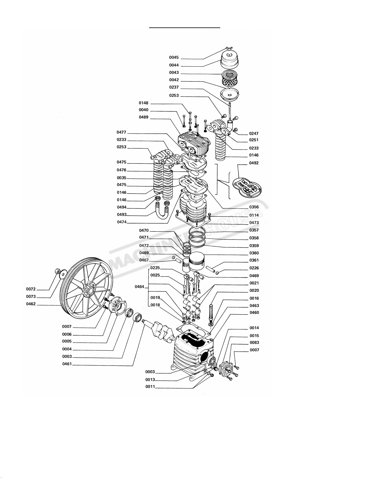
K25 PUMP
Page 9
Instruction Manual for K25SDL (C511)
19/12/2014
www.pilotair.com.au
 Loading...