


1/4 scale 1936 WACO YKS-6 “Custom Cabin” ARF
Wingspan: 100 in. (2540mm)
Length: 74 in. (1880mm)
Wing Area: 2496 in². (161dm²)
Flying Weight: 352 oz. (9.98kg)
1

Introduction & History
WACO is pronounced “wah-co” It rhymes with taco. The WACO Aircraft Co has no
relation to Waco, Texas, which by the way, is pronounced “way-ko.”
“The WACO Aircraft Company of Troy, Ohio was the leading aircraft manufacturer of
civilian aircraft in the U. S. from 1928 - 1935. Beginning in 1921 as the Weaver Aircraft
Company in Lorain, Ohio, they moved to Troy in 1924 and became the Advance Aircraft
Company but kept the WACO logo. In 1929, the name was changed to simply the
WACO Aircraft Company.
WACO produced over 80 models during the years 1919 - 1946, including the large troop
carrying gliders used in all the major invasions during WWII. The best selling WACO
was the Model 10, with over 1100 being produced from 1927 - 1930. During the years
1939 - 1942, WACO also built just over 600 Model UPF-7's for the CAA and the Civilian
Pilot Training program. WACOs were also popular around the world and sold airplanes
to 37 different countries with Brazil being the largest buyer.” (WACO Air Museum online,
Oct. 2008)
Pilot-1 is pleased to announce the 1/4 scale WACO YKS-6 as part of the Golden Age
Civilian Series. The Pilot-1 WACO YKS-6 encompasses the same attributes in quality
construction and handling that made the original WACO a favorite for over 75 years.
Our engineers have spent countless hours developing a true-to-scale ARF that looks
and flies like the full-scale airplane. We know you will be pleased with its scale looks
and balanced maneuverability.
2

Before starting, use the Contents list to take an inventory and make sure it is complete.
If any parts are missing or are not of acceptable quality, contact Hobby-Lobby.com
Support at 1-866-WE-FLY-RC (1-866-933-5972)
Contents List
¨ Fuselage
¨ Engine Cowl and Plywood Attachment Ring
¨ Landing Gear and Plywood Inserts
¨ Wheels, Velcro, Misc Hardware
¨ Wings and Corrugated Ailerons
¨ Tube Wing Joiners
¨ Airfoil Aluminum Wing Struts
¨ Horizontal Tail and Elevator
¨ Vertical Tail and Rudder
¨ Long Carbon Fiber Pushrods for Tail
¨ Pull-pull cable for rudder and tailwheel
Additional Items Required
(electric version)
¨ 4-channel Aircraft Radio w/ Receiver (minimum)
¨ 10 to 12 Lipo cells in series (5000-6000mah)
¨ (5) Hitec HS-635 servos for electric version (add 1 more for gas)
¨ (2) 12” servo wire extensions
¨ 77 amp Jeti SPIN Brushless ESC
¨ AXI 5345/16 Brushless Motor
¨ APC 21x12W Propeller
¨ 5-minute and 30-minute Epoxy Glue
¨ Thin CA Glue
¨ Phillips screwdriver
¨ Hex Drivers
¨ Needle Nose Pliers
¨ Hobby Knife
¨ Soldering iron and electrical solder
3

1. Locate the parts shown for the aileron
installation.
2. Remove the servo mounting plate from the
lower wing panels. The mounting layout is
for the Hitec HS-635 standard servo.
Adjust as necessary if you are using a
different servo.
3. Drill the wood blocks with a 1.5mm drill
(1/16”).
4. Mount aileron servo to blocks with servo
screws. Make sure the aileron is centered
using a servo centering device.
5. Add a 12” heavy-duty servo extension to
the aileron servos.
6. Add a servo plug retainer or tape the
connection to protect against accidental
disconnection.
4

7. Slide the servo extension through the wing
to the root.
8. Install servo mounting plate with small
sheet metal screws.
9. Untape aileron from main wing panel.
10. Locate CA hinges, four will be used for
each aileron.
11. Ailerons and their mating surface have
been pre-slotted for CA hinges.
12. Insert CA hinges to their centers in each
slot on aileron.
13. Fold the CA hinge sharply upward, This
will keep them in place when inserting the
hinges in the main wing panel.
14. Install the aileron into position on the main
wing panel. Make sure to check the gap at
the root of the aileron and the fit at the tip.
15. With the aileron tight against wing and
deflected downward, use 3 drops per
hinge of thin CA to assure strong bonds.
Use paper towel to remove any excess CA
before drying.
5
16. Deflect aileron upwards and repeat
application for bottom of wing. Note very
small gap between aileron and wing.
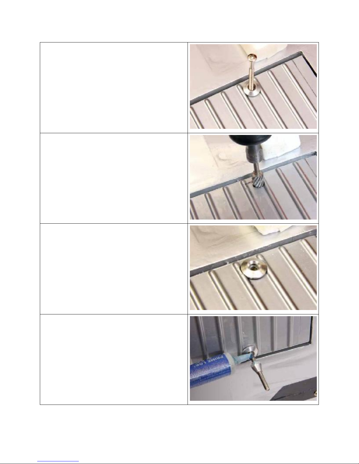
17. From the top of the wing install the aileron
control horn with its washer. DO NOT
tighten yet. Relieve the areas where the
washer touches the corrugations. This is
most easily accomplished with a Dremel.
18. After marking the location of the washer
use a Dremel to trim the corrugations.
19. Work carefully to maintain a close fit to the
washer. (See Photo)
20. Repeat the process for the underside of
the aileron.
21. Assemble the aileron control horn and use
a drop of thread locker to avoid the unit
loosening due to vibration. Snug the nut
tight but do not overtighten.
6

22. Screw nylon control horn linkage to the
control horn. The distance from the bottom
of the aileron to the center of the hole on
the nylon part should be about 28mm
(1-1/8”).
23. Prepare 3 full size servos for installation,
we recommend the Hitec HS-635.
24. Install the servo arms as shown in the
photo.
25. Locate the 2 long elevator pushrods.
26. Install 2-HS-635 Hitec servos into outer
mount locations with arms pointing toward
center of fuselage. (See Photo) A short
Phillips screwdriver is required.
27. Slide the elevator pushrods into position
and install each clevis into servo arm
about 25mm (1”) from the center.
28. We will come back to the rudder servo
installation in a few steps.
29. Locate the parts for the tailwheel
assembly.
7

30. Mount the aluminum plate to the bottom of
the fuselage with 3 screws. The bend in
the aluminum plate goes down.
(See photo)
31. Locate horizontal stabilizer and elevators
along with 6 CA hinges. Repeat the
assembly process similar to the ailerons.
Make sure to adjust the gaps in the hinge
line as well as the end gaps prior to
gluing.
32. Epoxy horizontal tail into position on the
fuselage making sure to center accurately.
33. Prepare the vertical fin and rudder for
installation. Install CA hinges in rudder
and fin.
34. NOTE: Tail wheel must be installed at the
same time as the rudder.
35. Epoxy vertical fin and rudder in place
along with the tailwheel steering arm.
(See photo)
36. Locate the Pull-Pull rudder control parts.
2 lengths of cable, 4 metal clevises and 4
metal crimp tubes.
8
37. Thread the bare end of each cable into
fuselage at rear. A tube is a pre-installed
for you. Pull all but a few inches of cable
to the front. Tape the rear of the cables so
that they remain accessible.
38. Install clevises at the front end of the
cables. Order of assembly: slide crimp on
wire, thread wire through hole in clevis,
return through crimp, loop end around
through front of crimp again.
39. It is easiest to complete the cable setup at
the servo end prior to installing the servo
in the fuselage.
40. Install servo in center hole in fuselage.
41. Un-tape the cables at the rear of the
fuselage and thread the pull-pull cables
through the clevises. Just get the basic
cable threading done but DO NOT crimp
yet.
42. Install the pull-pull control horn through
the rudder and center. Use thread locker
to keep the unit tight.
43. Install the nylon horns on the threaded
rod.
44. TIP: Connect the rudder servo to a servo
centering device and center the servo.
Leave connected during the cable
adjusting process.
45. After you are satisfied that you have the
cable lengths correct for centering your
rudder, and that the servo is still in its
neutral position, crimp the wire in position.
9

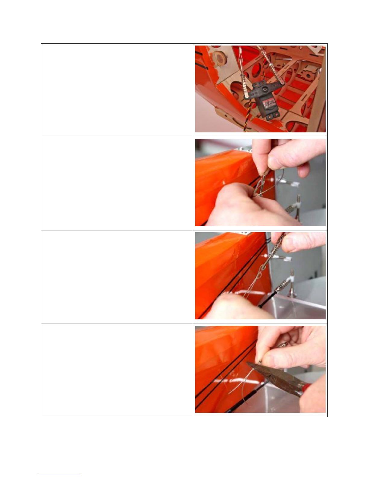
46. Photo shows the elevator and rudder
controls. Tighten the lock nut to maintain
the settings.
47. Clip the excess wire in front of the crimp.
48. Locate the pre-painted wire landing gear
parts as well as the 2 wooden fillers and
the 2 nylon landing gear straps and
screws.
49. Insert the landing gear into the pockets on
the fuselage making sure to avoid
puncturing the covering with the rear
landing gear wire.
50. Seat gear fully into position and insert the
rear wire in the pre-drilled hole near the
front edge of the lower wing. (See photo)
51. Spread epoxy on the sides and edges of
the wooden fillers.
10

52. Insert glued filler in position. Have a small
hammer handy to tap the block in place.
53. When fully sheeted the wooden block will
still protrude a small amount.
54. Use a paper towel and rubbing alcohol to
remove an epoxy that has squeezed out.
55. Repeat process for the other side.
56. Place the nylon landing gear strap in
position. (See photo)
57. Drill a pilot hole for the mounting screws.
58. Screw strap into position.
11

59. After the epoxy has cured sand the
wooden filler blocks flush with the
fuselage. This is most easily accomplished
by using a Dremel with a sanding drum.
Work carefully to not damage the finished
fuselage.
60. Once satisfied with the fillers, cut 2
patches from the supplied orange
covering to hide the installation.
61. Using a covering iron with a sock on it,
iron the covering into position.
62. Locate the gear leg covers and their
inserts.
12

63. After trial fitting, epoxy the gear legs into
position.
64. Insert balsa strips into the groove to finish
the inside of the gear leg.
65. Once satisfied with the position of the
fillers, CA them in place with thin CA.
66. Cut lengths of orange covering to finish
the interior of the gear legs. Iron one edge
of the covering into position.
13

67. Slit the covering to go around the smaller
wire and complete the ironing process.
68. Locate the scale wheels.
69. Slip one wheel collar on the axel then the
wheel and another wheel collar.
70. Tighten wheel collars.
NOTE: The nuts on the wheel disc face the
inside of the model. (see photo)
14

71. Install the 2 wing tubes. The longer one
(approx. 25”) is the bottom tube. The
shorter tube (approx. 21-1/2”) is for the
upper wing.
72. Slide the 4 wing panels into position.
73. Locate the 4 hitch pins. The wing panels
are held in place with these pins, no
screws of bolts are required.
74. Press the hitch pin into position to hold the
wing panel in place.
NOTE: For convenience and to avoid the
chance of forgetting or losing the pins, we
suggest that you use a short length of string
and tether each of the pins near where they
are to be used.
15

75. Locate the 8 pre-painted airfoiled
aluminum wing struts.
76. Locate the hardware for the struts.
16 Nylon fittings pre-drilled.
4- 3x30mm screws (shorten to 25mm)
8- 3x15mm screws
16- 3x10mm screws
28- 3mm nylock nuts
77. Install 2 nylon fittings with on 3x25mm
screw and one 3mm nyloc nut. Orient the
nuts toward the middle of the wing.
78. For the single fitting locations use the
3x15mm screw and 3mm nylock nut.
16
79. When all fittings are installed on the wings
begin to install the struts with the long
diagonal strut.
80. Attach the bottom of the strut to the single
fitting on the leading edge of the bottom
wing, make sure to align the airfoil with the
thick end forward. Use a 3x10mm screw
and a 3mm nylock nut.
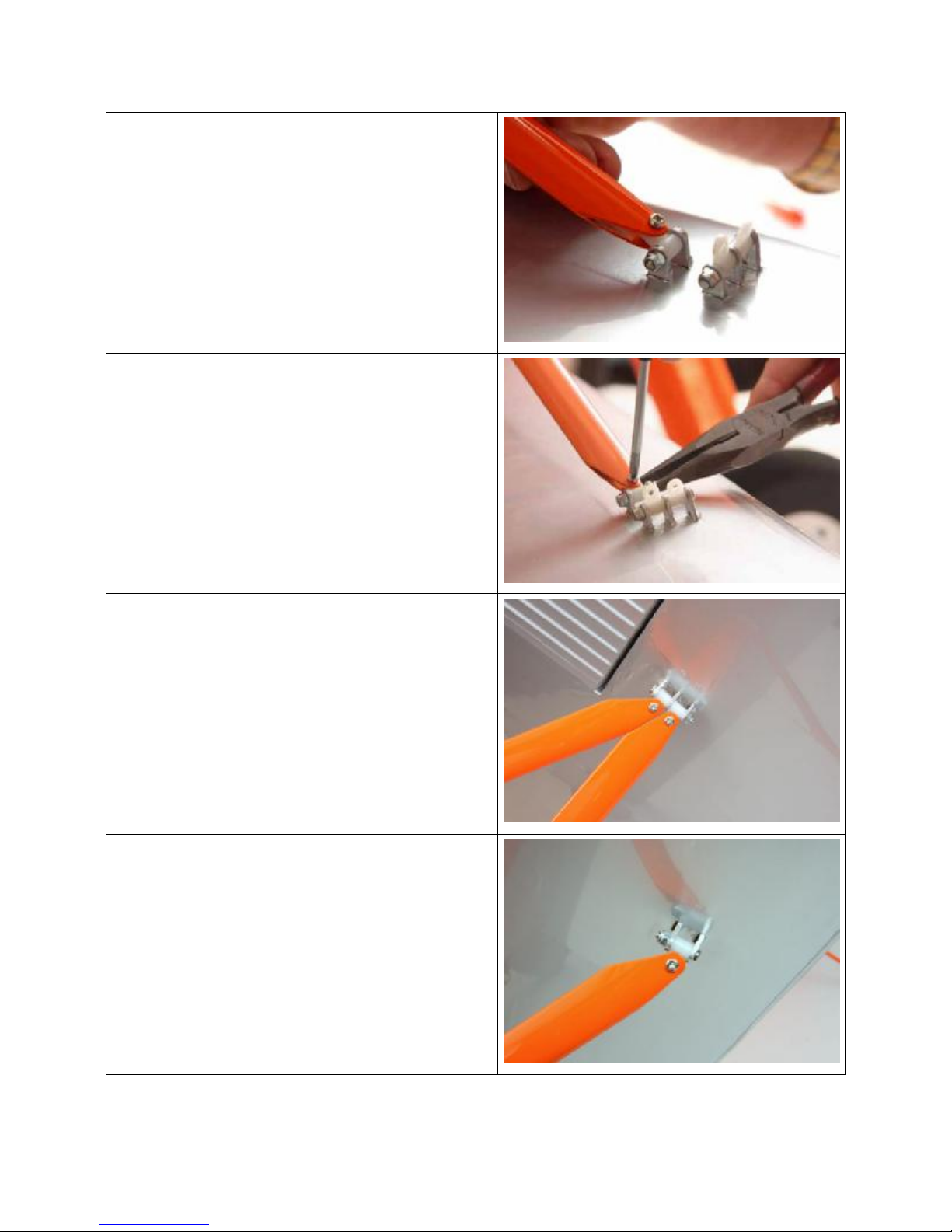
81. Hold the nut with a pair of needle nose
pliers while you screw the Phillips head in
place. Repeat at the upper end.
82. The N struts are 3 different lengths with
the longest at the rear, the shortest in the
middle (the diagonal) and the middle
length strut at the front. The photo shows
the upper connection of the N struts at the
rear of the wing.
83. Photo shows the upper connection of the
N strut at the front of the wing.
17

84. Photo from the rear of the diagonal strut
and the N struts at the front of the lower
wing.
85. Photo of the rear N strut connection at the
rear of the lower wing.
86. Install all hardware and snug each nut, do
not over tighten.
87. Locate the hardware for the aileron
interconnection.
4-Nylon connectors
4-3mm nylock nuts
2-Pre-painted inter connectors
88. Screw the nylon part to the pre-installed
threaded stud at the trailing edge of the
ailerons, secure with 3mm nylock nut.
89. Install aileron inter connector celvis to the
nylon part.
18
90. Adjust the length of the inter connector so
that both upper and lower aileron are in
neutral position.
91. Connect and tighten lock nuts to secure.
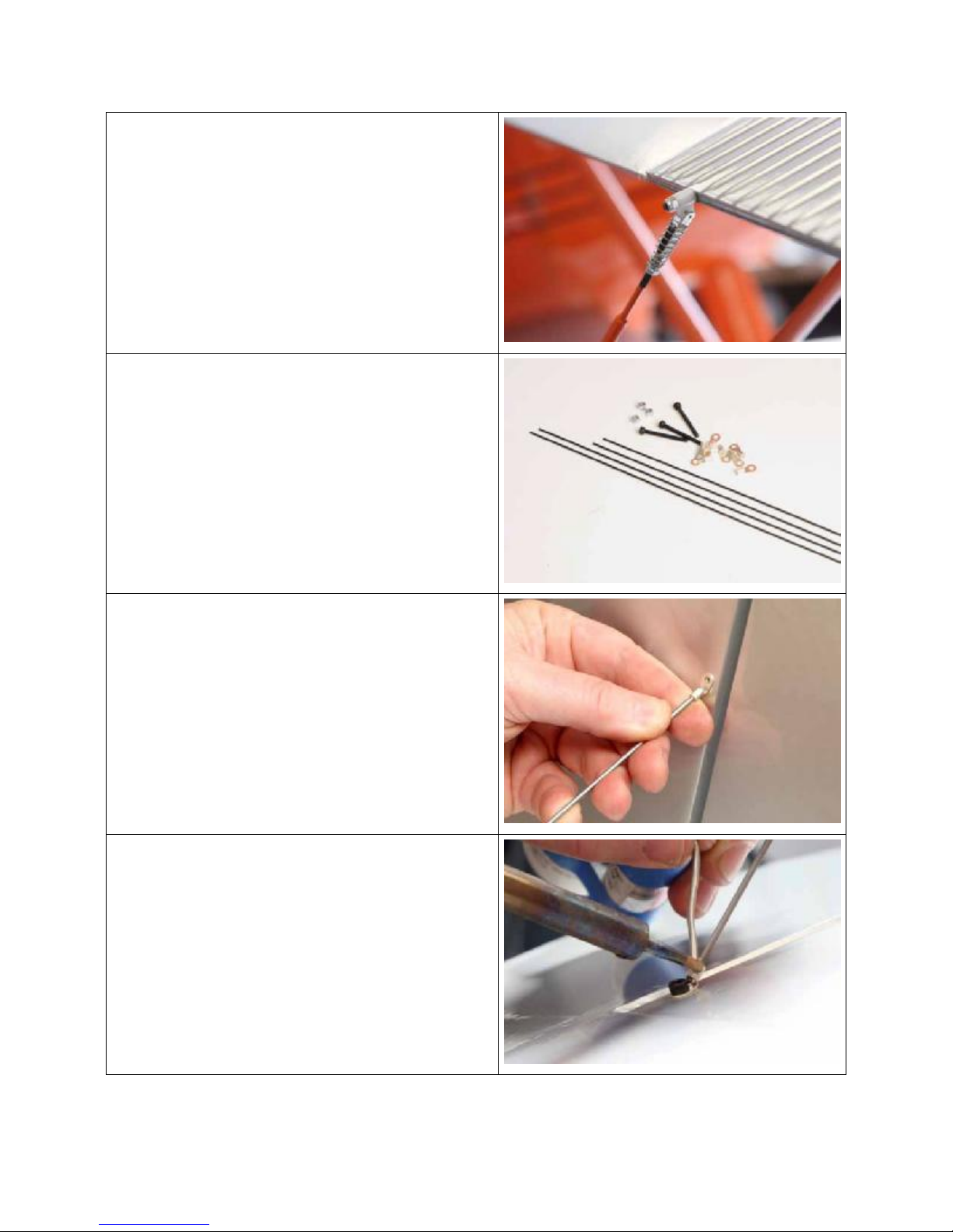
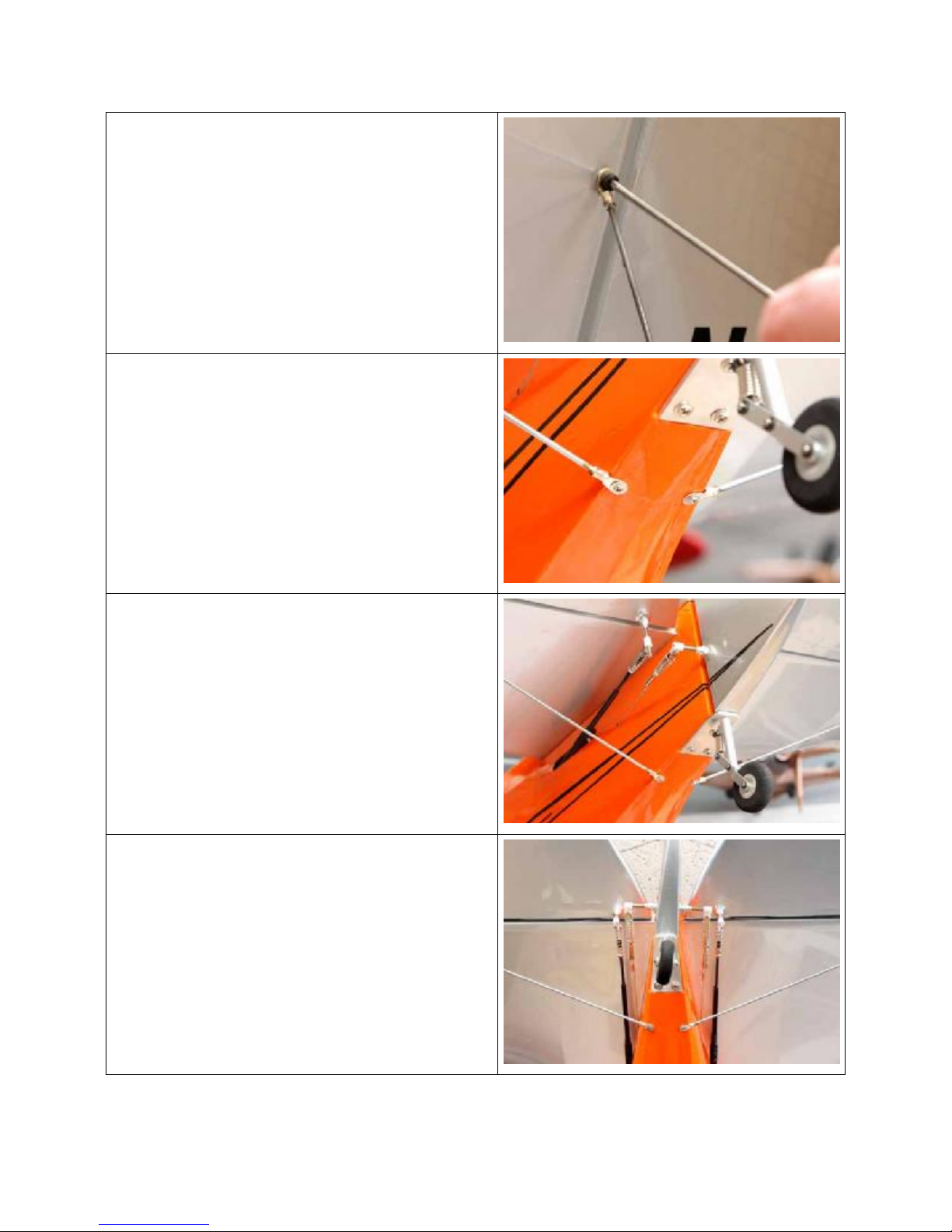
92. Locate the tail brace wires and solder on
electrical ends as well as the 3-3mm allen
head screws and 3mm nylock nuts.
93. You will be soldering the ring electrical
connectors to the ends of the brace wires.
94. Pre-bend one of the solder-on connectors
as shown in the photo.
95. Solder the connector to the brace wire.
96. Adjust the length of the brace wire and
solder it in place with the connector held
with the bolt. (See photo)
19
97. Tighten the 3 threaded allen head bolts.
98. On the bottom brace wires solder the
terminal so that a wood screw can be
used to attach it to the fuselage. Pre-drill
the fitting before installing the screws.
99. See photo for the location of the brace
wires.
100. Photo shows the general layout of tail
parts.
101. Bottom view of elevator pushrods, pullpull rudder with tail wheel steering and the
lower mount points for the tail brace wires.
20
102. You may wish to paint the interior of
the fiberglass cowl with a matt finish black
paint.
103. Put the dummy motor into the cowl but
DO NOT glue in place at this time.
104. The cowl mounting ring is pre-installed
at the factory. Installation is by placing the
cowl over the cowl mount screws and
rotating slightly in a counter-clockwise
direction to hold in place.
105. Before flying you may choose to
tighten several of the screws by using a
long Phillips screwdriver from the front of
the cowl.
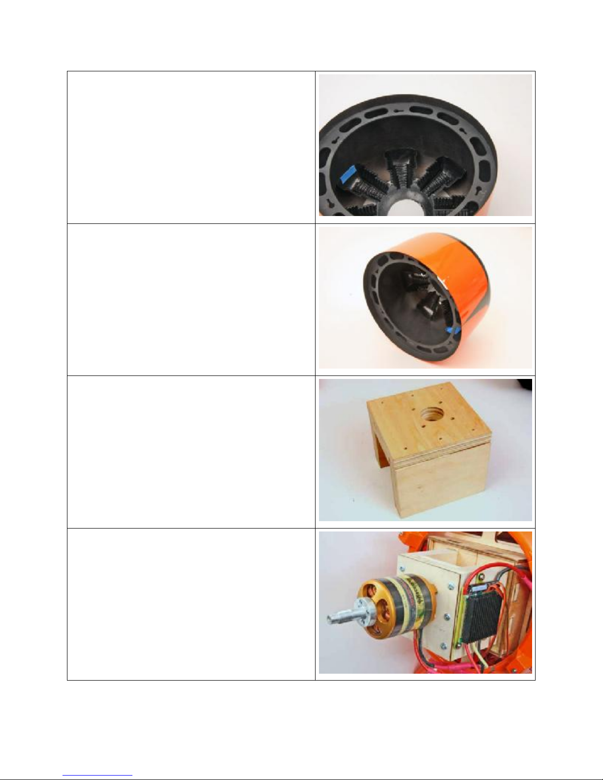
106. Locate the wooden AXI motor mounts
107. There is a light line burned on the 2
side pieces, this line is 15mm from one
edge of the plywood. If you are using a
5330 series motor, assemble the parts
without modification.
108. If you are using the 5345 series motor
you will need to cut off 15mm of each side
to achieve the proper motor distance from
the firewall.
109. Install the motor on the front mount
and screw the front face to the sides, do
not glue the front plate to the sides.
110. Epoxy this unit to the firewall box using
the centering reference that is burned into
the firewall.
111. If you wish to screw this mount to the
firewall block, pre-drill some pilot holes
and screw the mount in place from inside
the fuselage.
21
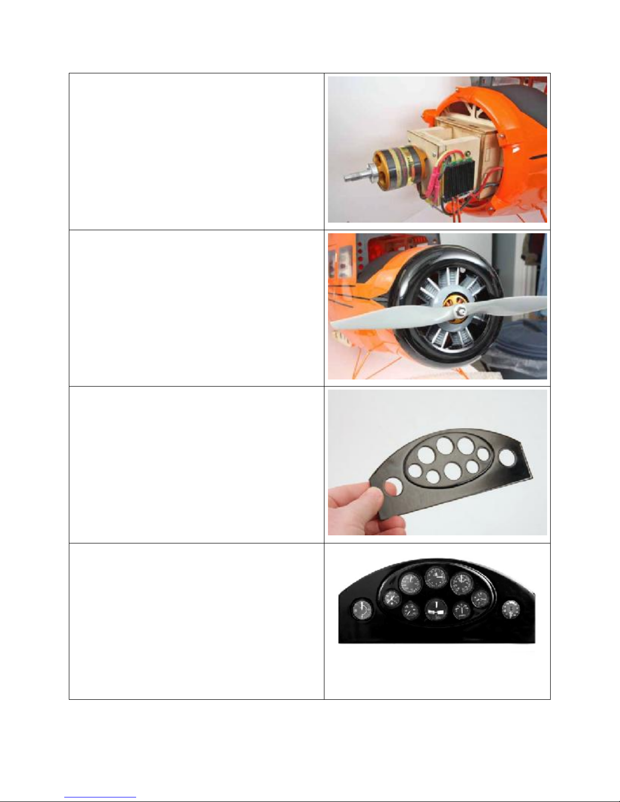
112. Photo shows AXI5345/16 motor and a
Jeti 99A SPIN ESC. The ESC is screwed
to the side of the motor mount and it is in
the airflow inside the cowl.
113. The power wires are routed back to a
Series connector in the battery box inside
the fuselage. This series connector has 3
male Deans connectors, 2 for connection
to flight batteries and 1 to be used with a
jumper female Deans as an arming plug.
114. Photo shows cowl mounted and the
dummy radial engine with the center
relieved for the electric motor. Dummy
motor has been detailed with some paint
and self-stick aluminum tape on the
pushrods. Propeller is an APC 21x12W
electric prop.
115. A pre-assembled and painted
instrument panel is provided.
116. There is a printed sheet with the
instruments at the rear of the manual. You
can cut this out and attach it to the rear of
the panel.
117. Scale instruments with raised bezels
and clear faces in color are available from
Hobby Lobby. The holes in the panel are
designed for these instruments. HL part#
PP41008 American Aircraft of the 30’s
22
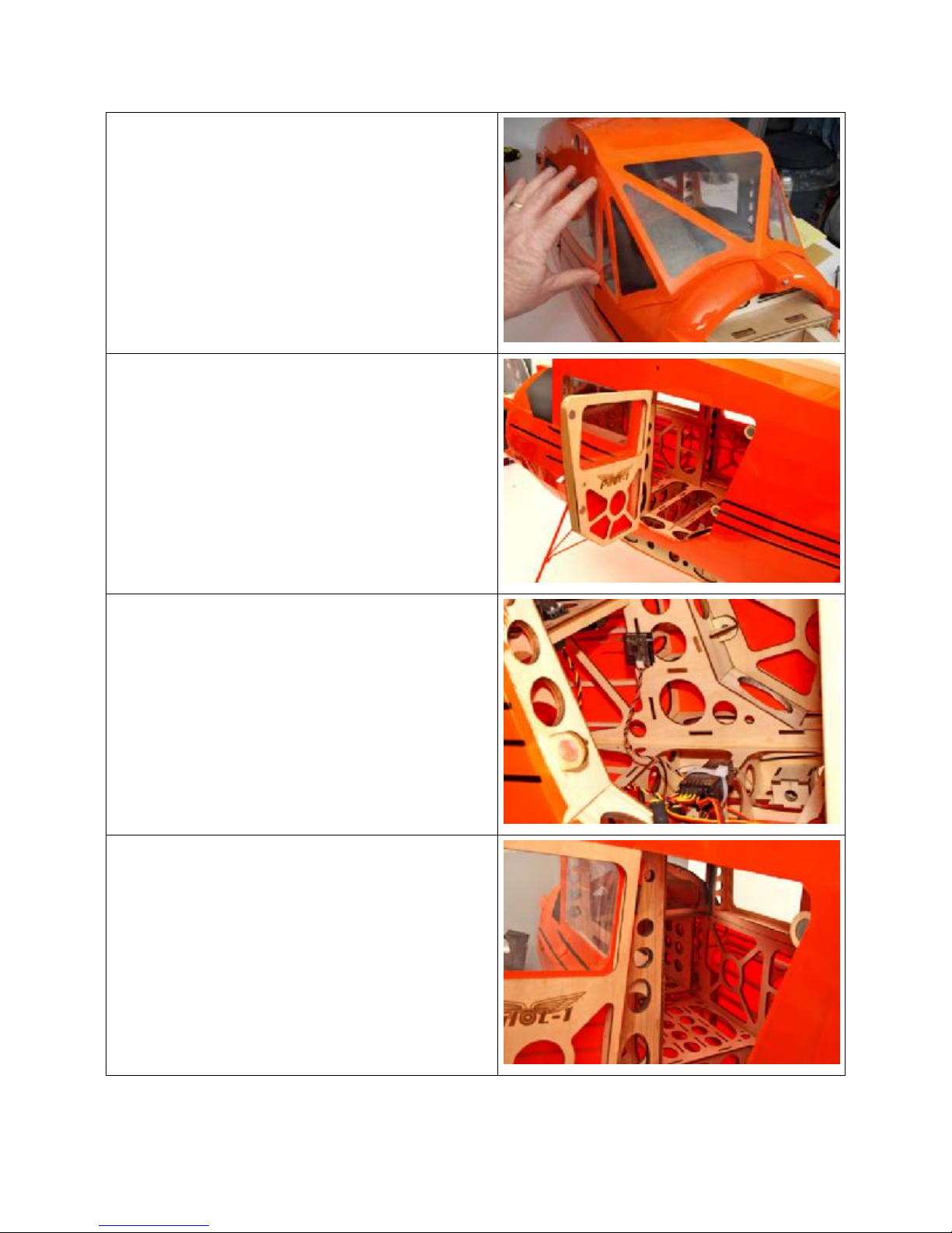
118. Fit the windshield and attach either
with small screws or canopy glue.
119. Access to the radio system and the
batteries is through the operable doors.
120. In addition to flight batteries you will
need to supply your radio system with
power. Use an external BEC like the Jeti
JE512 combined with a 2-cell 21002500mAh Lipo pack. The BEC can be set
to 6V output for stronger servo response.
121. Secure this system to the front of the
cabin with Velcro and cable ties.
122. Locate your radio receiver on the floor
of the cabin with easy access. 6” servo
extensions on the 2 aileron channels of
the receiver will make connecting the
ailerons easier.
123. Make sure to label them so that an
inadvertent misconnection is avoided.
124. Flight batteries are installed in the
inside of the motor box in the nose of the
aircraft. You will need to build a platform
on which to attach the batteries. The exact
dimensions of this will be determined by
your choice of batteries. Make sure that
they are secure before flight.
125. Two 6-cell 5000mAh Thunder Power
packs balanced our airplane without any
additional ballast.
23
126. To remove the wing panels as sets first
remove the hitch pins.
127. Unplug the aileron extensions from
your receiver and slide the wings away
from the side of the fuselage about 2-3”.
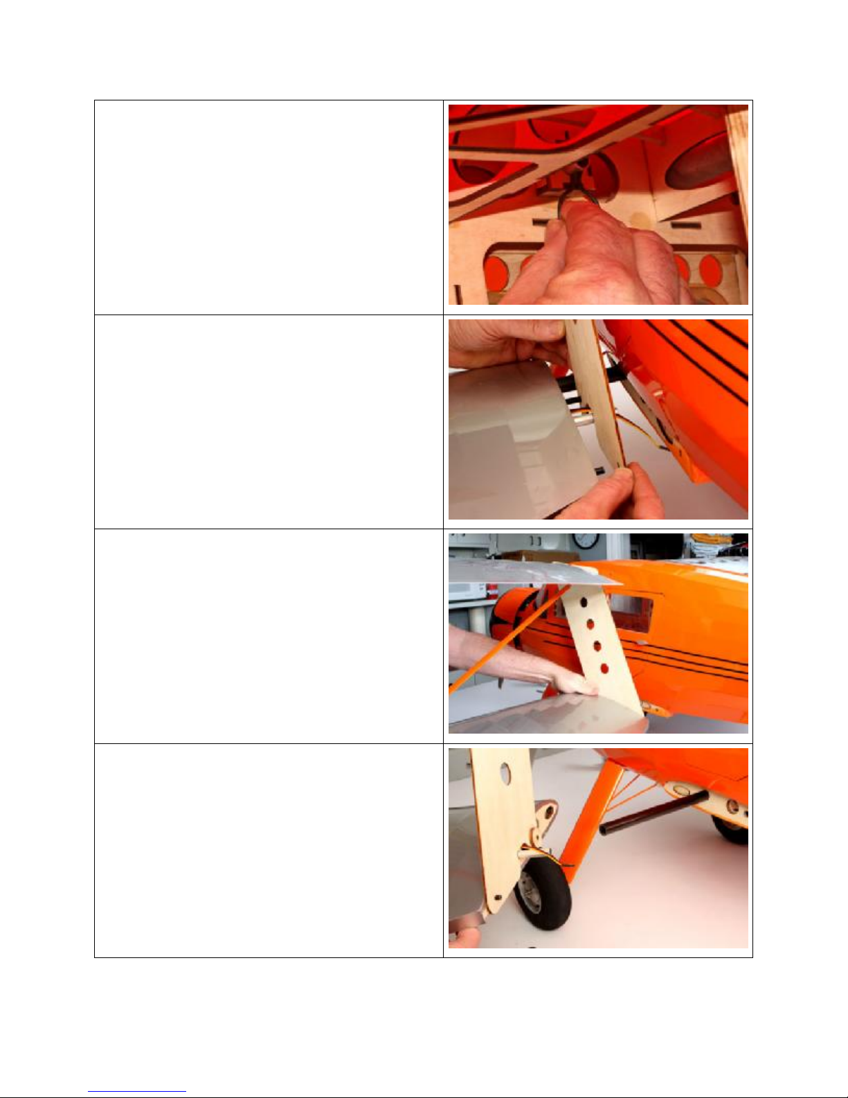
128. Slip the provided plywood wing jig into
place one both the lower and upper root
ribs.
129. With the ply jig in place slide the wing
set the rest of the way off of the tube
joiners.
130. The operation should take less than a
minute per side of the aircraft.
24
131. The wings transport easily beside the
fuselage for quick and pain free assembly
at the flying field.
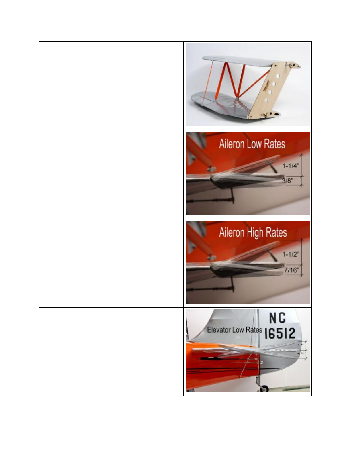
Aileron Low Rates:
1-1/4” UP
3/8” DOWN
Aileron High Rates
1-1/2” UP
7/16” DOWN
Elevator Low Rates
1” UP
1” DOWN
25

Elevator High Rates
1-3/4” UP
1-3/4” DOWN
Rudder Low Rates
1” in each direction
Rudder High Rates
1-1/2” in each direction
CG
6” back from the leading
edge of the upper wing where
it meets the fuselage
NOTE: This is about in line with the leading
Edge of the lower wing
26

Instrument panel can be cut out and installed behind the wooden panel.
Preflight
If you are new to flying R/C aircraft, or a seasoned modeler, we recommend you have a fellow R/C
modeler help you with the first flight. Some items you will need to complete on your first preflight are:
1. Aircraft assembled correctly and ready for flight.
2. All control throws and expos are set per this manual.
3. Transmitter fully charged and on correct model.
4. Aircraft balances at the recommended location.
5. Flight Battery is fully charged and secure.
6. All electronics are operating correctly, proper direction, and secure.
7. Complete a radio Range Check per your radio manual.
8. Balance propeller and make sure it is secure.
9. Wait for a calm or light wind day for first flights.
Flying
You will soon find out the Pilot-1 Cabin WACO YKS-6 is a real pleasure to fly. Takeoffs, landings, and
scale aerobatics are easy and well behaved. Even if you have never flown a tailwheel airplane before, the
Pilot-1 Cabin WACO YKS-6 should be an easy transition. Landings are best accomplished by “threepointing.” This means that all three wheels should touch at the same time and a little up-elevator is held
until the aircraft comes to a complete stop. Except for takeoff and climb, you will only use about 1/2
throttle to maintain a scale flying speed. You can expect flight times of 8+ minutes depending on battery
used and throttle management.
We hope you enjoy your Pilot-1 Cabin WACO YKS-6 as much as we do!
Happy Landings!
27

WARNING – THIS IS NOT A TOY!
Radio controlled model aircraft are capable of inflicting serious injury and/or property damage if not assembled, operated, and
maintained in a competent and safe manner. If you are not already experienced with radio controlled models, we strongly suggest
Hobby-Lobby guarantees this kit to be free from defects in both material and workmanship at the date of purchase. This warranty
does not cover any component parts damaged by use or modification. In no event shall Hobby-Lobby’s liability exceed the original
that you find an experienced modeler to assist you.
Warranty
cost of the purchased kit.
2008 Official Academy of Model Aeronautics National Model Aircraft Safety Code
1. A model aircraft shall be defined as a non-human-carrying device capable of sustained flight in the atmosphere. It shall
not exceed limitations established in this code and is intended to be used exclusively for recreational or competition
activity.
2. The maximum takeoff weight of a model aircraft, including fuel, is 55 pounds, except for those flown under the AMA
Experimental Aircraft Rules.
3. I will abide by this Safety Code and all rules established for the flying site I use. I will not willfully fly my model aircraft in a
reckless and/or dangerous manner.
4. I will not fly my model aircraft in sanctioned events, air shows, or model demonstrations until it has been proven airworthy.
5. I will not fly my model aircraft higher than approximately 400 feet above ground level, when within three (3) miles of an
airport without notifying the airport operator. I will yield the right-of-way and avoid flying in the proximity of full-scale
aircraft, utilizing a spotter when appropriate.
6. I will not fly my model aircraft unless it is identified with my name and address, or AMA number, inside or affixed to the
outside of the model aircraft. This does not apply to model aircraft flown indoors.
7. I will not operate model aircraft with metal-blade propellers or with gaseous boosts (other than air), nor will I operate
model aircraft with fuels containing tetranitromethane or hydrazine.
8. I will not operate model aircraft carrying pyrotechnic devices which explode burn, or propel a projectile of any kind.
Exceptions include Free Flight fuses or devices that burn producing smoke and are securely attached to the model aircraft
during flight. Rocket motors up to a G-series size may be used, provided they remain firmly attached to the model aircraft
during flight. Model rockets may be flown in accordance with the National Model Rocketry Safety Code; however, they
may not be launched from model aircraft. Officially designated AMA Air Show Teams (AST) are authorized to use devices
and practices as defined within the Air Show Advisory Committee Document.
9. I will not operate my model aircraft while under the influence of alcohol or within eight (8) hours of having consumed
alcohol.
10. I will not operate my model aircraft while using any drug which could adversely affect my ability to safely control my model
aircraft.
11. Children under six (6) years old are only allowed on a flightline or in a flight area as a pilot or while under flight instruction.
12. When and where required by rule, helmets must be properly worn and fastened. They must be OSHA, DOT, ANSI,
SNELL or NOCSAE approved or comply with comparable standards.
GENERAL
RADIO CONTROL
1. All model flying shall be conducted in a manner to avoid over flight of unprotected people.
2. I will have completed a successful radio equipment ground-range check before the first flight of a new or repaired model
aircraft.
3. I will not fly my model aircraft in the presence of spectators until I become a proficient flier, unless I am assisted by an
experienced pilot.
4. At all flying sites a line must be established, in front of which all flying takes place. Only personnel associated with flying
the model aircraft are allowed at or in front of the line. In the case of airshows demonstrations straight line must be
established. An area away from the line must be maintained for spectators. Intentional flying behind the line is prohibited.
5. I will operate my model aircraft using only radio-control frequencies currently allowed by the Federal Communications
Commission (FCC). Only individuals properly licensed by the FCC are authorized to operate equipment on Amateur Band
frequencies.
6. I will not knowingly operate my model aircraft within three (3) miles of any preexisting flying site without a frequency-
management agreement. A frequency management agreement may be an
allocation of frequencies for each site, a day-use agreement between sites, or testing which determines that no
interference exists. A frequency-management agreement may exist between two or more AMA chartered clubs, AMA
clubs and individual AMA members, or individual AMA members. Frequency-management agreements, including an
interference test report if the agreement indicates no interference exists, will be signed by all parties and copies provided
to AMA Headquarters.
7. With the exception of events flown under official AMA rules, no powered model may be flown outdoors closer than 25 feet
to any individual, except for the pilot and located at the flightline.
8. Under no circumstances may a pilot or other person touch a model aircraft in flight while it is still under power, except to
divert it from striking an individual.
28

9. Radio-controlled night flying is limited to low-performance model aircraft (less than 100 mph). The model aircraft must be
equipped with a lighting system which clearly defines the aircraft's attitude and direction at all times.
10. The operator of a radio-controlled model aircraft shall control it during the entire flight, maintaining visual contact without
enhancement other than by corrective lenses that are prescribed for the pilot. No model aircraft shall be equipped with
devices which allow it to be flown to a selected location which is beyond the visual range of the pilot.
Hobby Lobby International, Inc.
5614 Franklin Pike Circle
Brentwood, TN 37027
1-866-WE-FLY-RC
(1-866-933-5972)
www.hobby-lobby.com
29
 Loading...