

Page 1

PILOMAT Srl Unipersonale
24050 Grassobbio (BG) – Italy – Via Zanica, 17/P
Tel. +39 035 297220 – fax +39 035 297094
e-mail : [email protected] www.pilomat.com
Cod. Fisc. e Part. IVA 00383760162 – Cap. Soc. 46.800,00 i.v. R.E.A. BG n.142721 – Isc. Reg. Imp. 00383760162 A.N.C. 9549211 I.M.Q. 1301
PILOMAT ROAD BLOCKER RB500
CODE: PW500X000
TECHNICAL INSTRUCTIONS
______________________________________________________
Page 2

PILOMAT Srl Unipersonale
24050 Grassobbio (BG) – Italy – Via Zanica, 17/P
Tel. +39 035 297220 – fax +39 035 297094
e-mail : [email protected] www.pilomat.com
Cod. Fisc. e Part. IVA 00383760162 – Cap. Soc. 46.800,00 i.v. R.E.A. BG n.142721 – Isc. Reg. Imp. 00383760162 A.N.C. 9549211 I.M.Q. 1301
WARNINGS FOR THE INS
TALLER
– GENERAL SAFETY OBLIG
ATIONS
ATTENTION! It is very important for th
e safety of people to follow all
instructions strictly. A wrong installation or use of the product could
cause serious damage to people.
17 Each automatic installation should have at least one lighting device
(i.e: flashing lights integrated in the crosshead of the bollard) and a signal
placard, along with the device quoted at point “16”
2 Read carefully this manual
before starting installation and save it for
future reference.
18 In each automatic installation
the installer must consider and install
appropriate safety devices.
3 Packaging materials (i.e. plastic, polystyrene, etc.) must be out of
children’s reach, because potentially dangerous.
19 For maintenance works use only original parts supplied by Pilomat S.r.l.
4 This product has been designed a
nd manufactured exclusively on the
purpose indicated in this manual. Any different use not here indicated
could damage the integrity of the product and/or be potentially
dangerous.
20 Pilomat S.r.l. is not responsible for safety and good functioning of th
e
product , in case of use of components not manufactured or distributed by
Pilomat S.r.l.
5 Pilomat S.r.l. is not responsible for any damage caused by improper or
different use from the indicated one.
21 Do not apply any modification to the parts composi
ng the automated product
PILOMAT.
6 Do not install the device in an explosive area: Using Inflammable gases
could be not safe.
22 The installer must provide the Customer with all information related to the
manual release of the automatic bollard in case of emergency and give the
User a warning manual attached to the product.
7 Installation must be according to the local Laws.
23 Do not allow children or others to stop close to the bollard during operation.
8 In order to have an adequate safety level in
the extra
-
CEE countries, in
addiction to the national laws, the above mentioned laws must be
followed.
24 Keep remote controls or other impulse
-
giving devices out of children’s reach,
in order to avoid involuntary activation.
9 Pilomat S.r.l. is not resp
onsible if someone does not observes the correct
method of installation of the PILOMAT products and related devices,
included deformations coming during the use.
25 Thoroughfare over the Pilomat bollard allowed only at complete lowering of
the bollard.
10 Before any actions on the automatic installations take power off.
26
Semiautomatic bollards are not adviceable for multiple installation (two or
more) on main streets where the frequent passage of vehicles over the
lowered bollards can break the lock block and make the bollard lifting without
control.
11 An Omni polar switch should b
e foreseen on the alimentation’
s net of
automatic installations. Its connections should have an opening range of
3 mm. A magnetotermical differential with 6A Omni polar switch is
adviceable
27 The User must avoid any repairing actions or direct operations on the bollard,
and must address to qualified and authorized personnel only.
12 Assure that a differential switch with 0,03° is present at the beginning of
the automatic installation.
28 Do not waste exhausted batteries in the garbage, but dispose them in the
apposite containers to allow recycling. Disposal costs have already been paid
by the manufacturer
13 The main electrical alimentation of the control unit of automatic
installations must be connected directly to at the beginning of the
apposite principal switch set inside the control unit; use anti-flame cables
approved by at least one of the European Institutes. The dimension of
the first alimentation line must be minimum 3x2,5mm,but evaluated by
the installer according to the number of PILOMAT (400W each PILOMAT)
and the distance from the output point in order to guarantee a correct
alimentation (230V +/- 10% for moving PILOMAT).
29
The product is packaged on Euro
pallet; use pallets’ movers or shunters for
movement; handle with care.
14 Test that the earthing
is workmanlike
and connect the metallic parts.
30
The product has been manufactured with IP 56 protection’s level, and could
therefore be stored everywhere; storage in internal or covered places is
anyway preferable.
15 The automatic installations include a standard safety device: an inversion
pressure switch in case of at least 40 kg of load. It is anyway necessary to
test the activation level every six months, according to what laws
establish.
31 The product does not require availability of spare parts; Pilomat’ s warehouse
can send by express any needed spare parts.
16 Safety devices (Law EN 12978) allow protection of potentially dangerous
areas where activities such as squashing, conveyance, shearing are
possible to occur.
32 In case of maintenance and/or reparation, Pay attention not to give improper
raising signals; to avoid any problems, disconnect the bollard’s moving by the
switch set inside the control management station.
33 Everything not mentioned in this manual is not allowed.
Page 3

PILOMAT Srl Unipersonale
24050 Grassobbio (BG) – Italy – Via Zanica, 17/P
Tel. +39 035 297220 – fax +39 035 297094
e-mail : [email protected] www.pilomat.com
Cod. Fisc. e Part. IVA 00383760162 – Cap. Soc. 46.800,00 i.v. R.E.A. BG n.142721 – Isc. Reg. Imp. 00383760162 A.N.C. 9549211 I.M.Q. 1301
PRODUCER COMPLIANCE DECLARATION:
2006/42/EC - 2006/95/EC – 2004/108/EC
Producer: PILOMAT S.r.l.
Address: Via Zanica 17/P Grassobbio (BG – ITALY)
We state under our exclusive responsibility that the product
PILOMAT ROAD BLOCKER RB500 -
CODE: PW500X000
LINE NUMBER:
Is built to be integrated into a machine or to be assembled with other machinery to create a machine under
the provision of Directive 2006/42/EC
Conforms to the essential safety requirements of the following EEC directives:
- 2006/95/EC Low voltage directive
- 2004/108/EC Electromagnetic compatibility directive
And also declares that it is prohibited to put into service the machinery until the machine in which it will be
integrated or of which it will become a component has been identified and declares as conforming to the
conditions of Directive 2006/42/EC and subsequent amendments.
Grassobbio (BG – ITALY) 14.01.2015 Technical Manager
Sergio P.I. Toffetti
Page 4
PILOMAT Srl Unipersonale
24050 Grassobbio (BG) – Italy – Via Zanica, 17/P
Tel. +39 035 297220 – fax +39 035 297094
e-mail : [email protected] www.pilomat.com
Cod. Fisc. e Part. IVA 00383760162 – Cap. Soc. 46.800,00 i.v. R.E.A. BG n.142721 – Isc. Reg. Imp. 00383760162 A.N.C. 9549211 I.M.Q. 1301
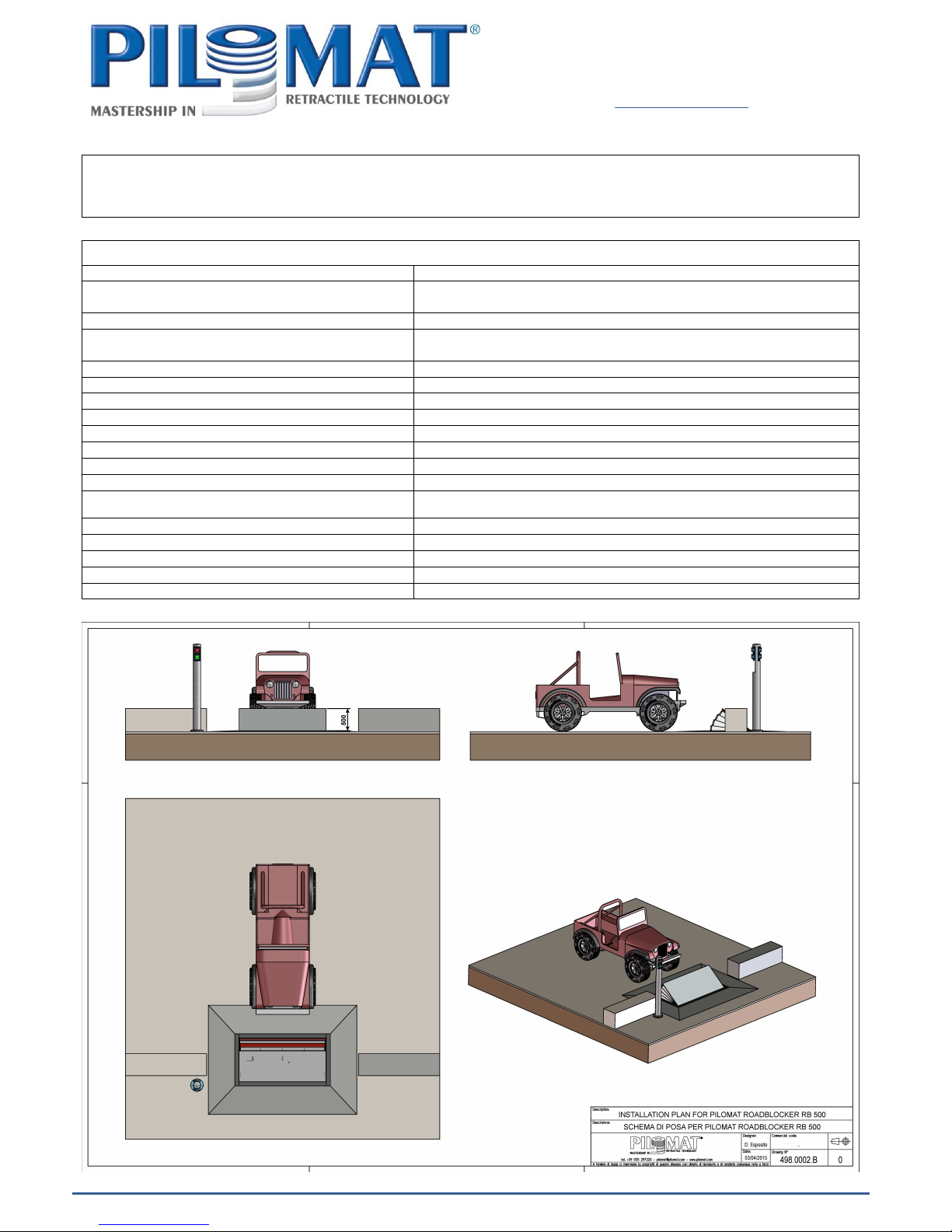
PILOMAT ROAD BLOCKER RB500
AUTOMATIC WITH BUILT-IN HYDRAULIC PUMP
DATA SHEET RB500
PLATFORM HEIGHT ABOVE GROUND
500 mm
PLATFORM WIDTH
STANDARD: 2,00m
– 3,00m
– 4,00m
– 5,00m
– 6,00m
(out of standard sizes evaluable)
ROAD BLOCKER DEPTH
290mm (SHALLOW MO
U
NTED)
DEPTH OF DIGGING (FOUNDATION AND ROAD
BLOCKER)
500mm
BREAKOUT RESISTANCE
700
.000 J. (REF. US. CERTIFICATIONS ASTM LEVEL M30)
USED MOVEMENT
HYDRAU
LIC
RISING SPEED
5”
POSSIBILITY TO SET FASTER SPEED (OUT OF STANDARD)
LOWERING SPEED
3”
POSSIBILITY TO SET FASTER SPEED (OUT OF STANDARD)
E.F.O CIRCUIT FOR EMERGENCY RISING
YES (OPTIONAL)
–
RISING SPEED 1,5”
DEVICE FOR MANUAL HANDLING
YES (OPTIONAL)
MULTILED FLASHING LIGHT (30 LED POINTS/M)
YES (OPTIONAL)
METAL SHUTTER FOR CLOSING FRONT AND SIDE
YES (OPTIONAL)
CONNECTION LINE TO CONTROL UNIT
STANDARD 10m (MAX: 30m)
–
POSSIBILITY TO EVALUATE GREATER LENGHTS (OUT OF
STANDARD)
PLATFORM FINISH
ALUMINIUM ANTISLIP METAL SHEET
–
OPTIONAL ANTISLIP STAINLESS STEEL
CLASS OF LOAD
REGULATION U.N.I.
- D400
TYPE OF USE
INTENSIVE
POWER SUPPLY
230V
(1P + N)
– 50/60Hz
–
1,1kW
STANDARD CABINET
WALL MOUNTING
- 700x500x20
0P mm
Page 5

PILOMAT Srl Unipersonale
24050 Grassobbio (BG) – Italy – Via Zanica, 17/P
Tel. +39 035 297220 – fax +39 035 297094
e-mail : [email protected] www.pilomat.com
Cod. Fisc. e Part. IVA 00383760162 – Cap. Soc. 46.800,00 i.v. R.E.A. BG n.142721 – Isc. Reg. Imp. 00383760162 A.N.C. 9549211 I.M.Q. 1301
PILOMAT ROAD BLOCKER RB500 - Width: 2,0mt
INSTALLATION SEQUENCE
The following laying sequence concerns the RB500 2,0m wide.
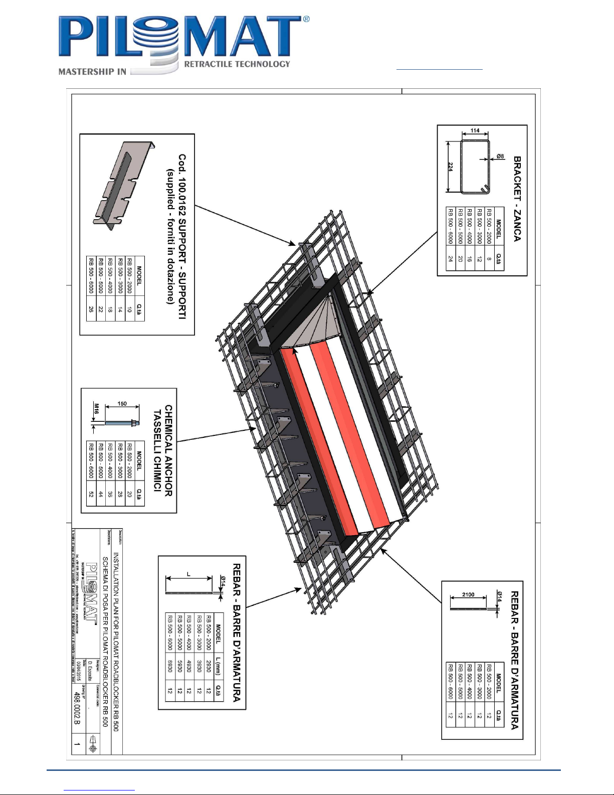
Rebars, brackets and chemical anchors are required for the installation (supplied by the
contractor). It is advisable to be euipped with them before starting the placing.
It is necessary for ROAD BLOCKER RB 500 - 2,0mt wide:
- N° 18 U-rebars 460x200mm – ferro tondo diametro 14mm.
- N° 12 linear rebars – bar Ø14mm, 2.930mm long.
- N° 12 linear rebars – bar Ø14mm, 2.100mm long.
- N° 8 brackets 224x114mm – bar Ø8mm.
- N° 20 chemical anchor HILTI (or similar). Reference HILTI = threaded bar: HIT-V-5.8
M16x150mm – injection chemical anchor: HIT-HY 200-A 330/2.
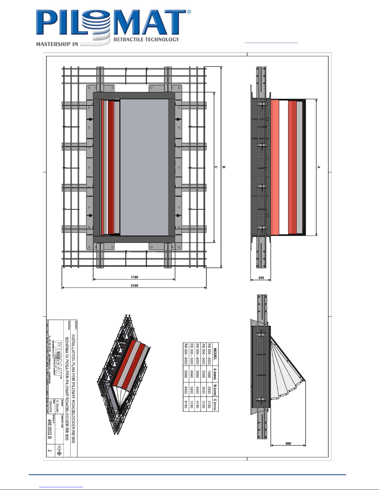
In case of a different width, refer to the related drawing; the sequence of installation
is the same but the size in width, the amount of the brackets, chemical anchors and
supports for reinforcing rods change.
1) The area of installation must be scanned for underground services. At the chosen
location, mark the ground for the laying of ROAD BLOCKER.
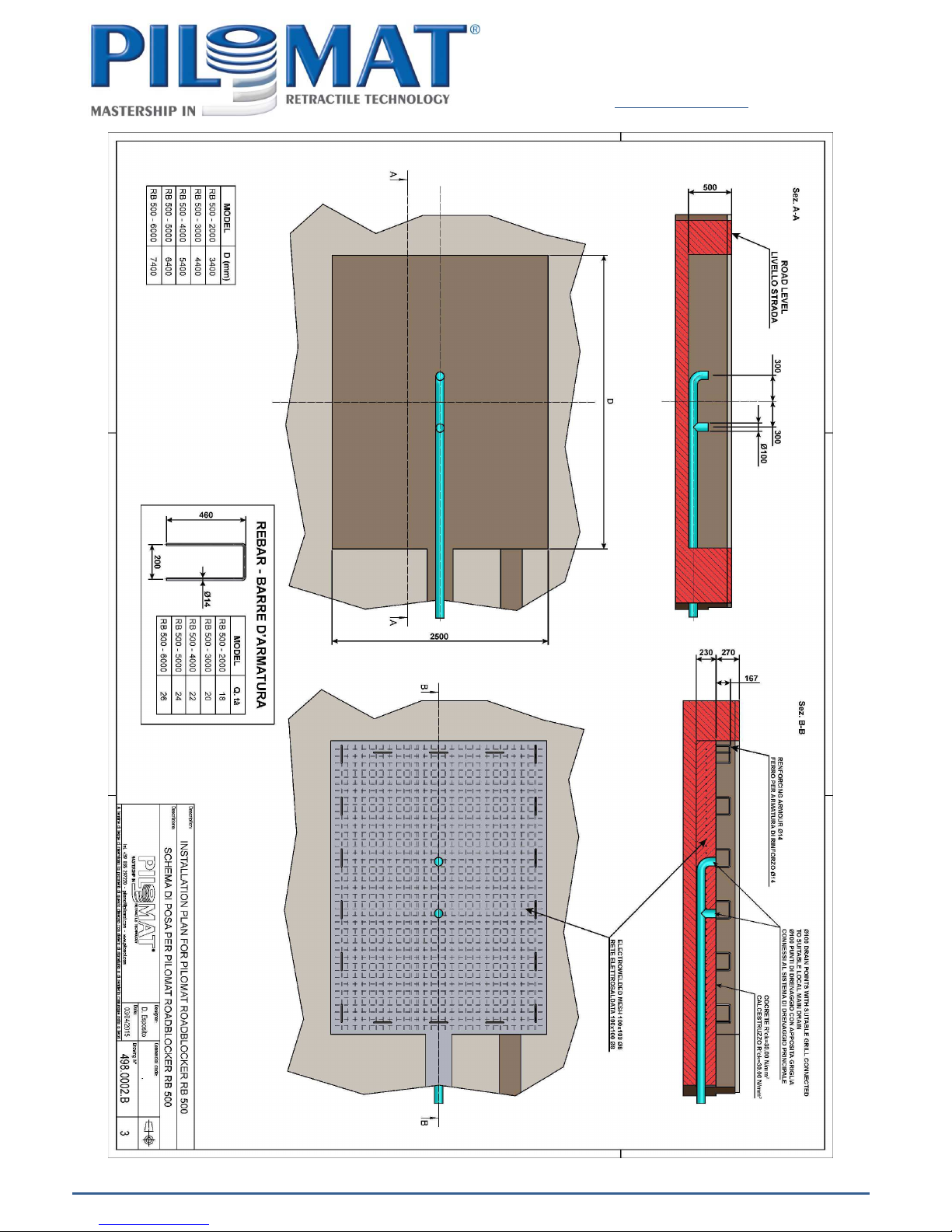
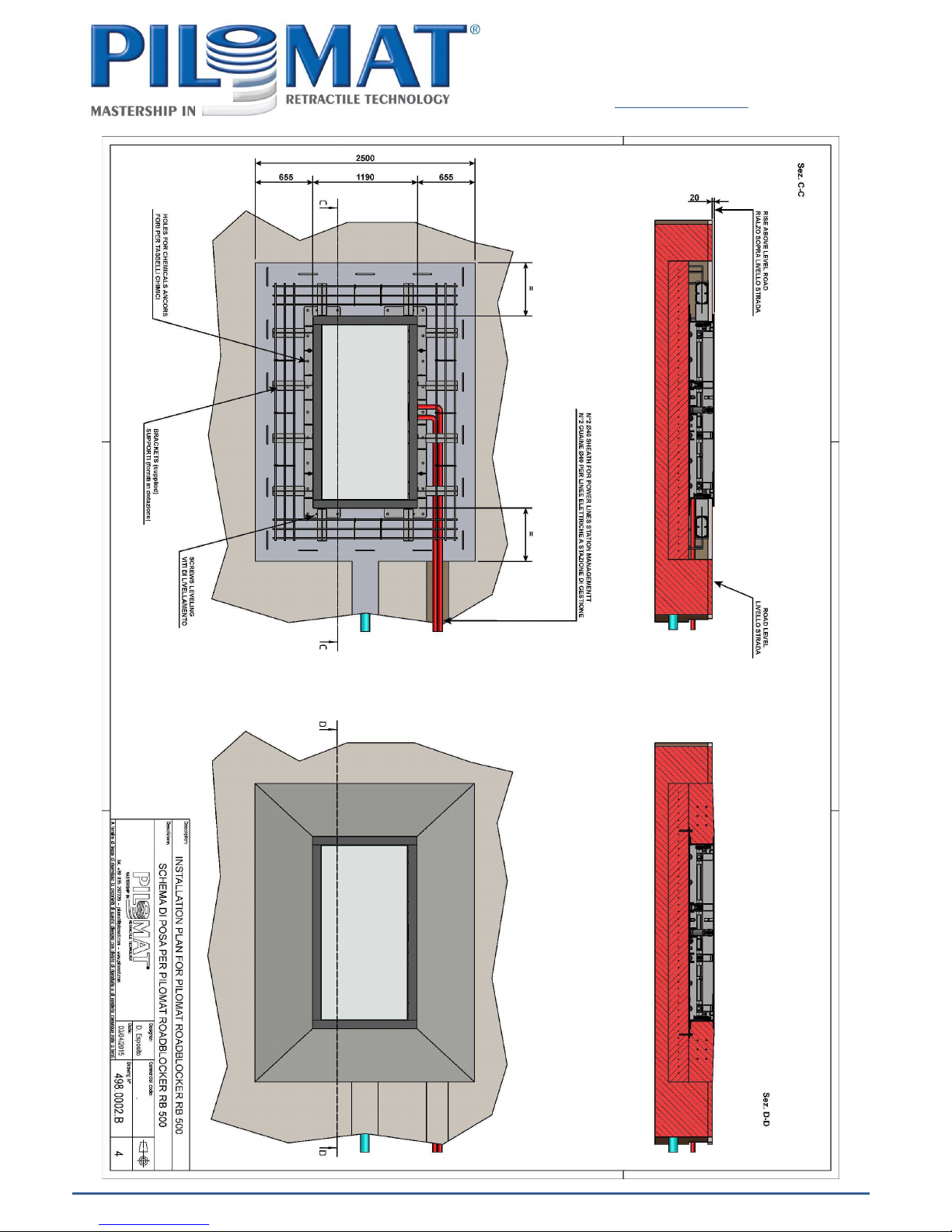
2) Dig a hole 2,50m wide and 3,40m long to a depth of about 0,50m (ref. drawing
498.0002-3); the excavation includes two Ø 40mm sheaths for connecting PILOMAT
ROAD BLOCKER to the control unit and a Ø 100mm pipe for rainwater drainage (ref.
drawing 498.0002.B-3).
3) Lay a Ø100mm pipe for rainwater drainage (supplied by the contractor), protected by
its dedicated grating (to avoid clogging); the piping must be properly connected to the
drainage system (ref. Drawing 498.0002.B-3).
4) Execute the flooring substrate (well leveled) to a thickness of about 230mm with a
concrete casting minimum Rck = 30,00N / mm2 (or higher). Lay a welded mesh
100x100mm wire Ø8mm (supplied by the contractor) and 18 U-rebars 460x200mm
wire Ø14mm (supplied by the contractor) stuck into the ground for about 60mm (ref.
drawing 498.0002.B-3). It is advisable to vibrate the concrete with a special electric
instrument.
- Once the flooring substrate is mature, place ROAD BLOCKER RB500 in the center
of the excavation. Screw the outer frame of ROAD BLOCKER with the 10 supports
provided for perimetral rebars (ref. drawing 498.0002.B-1). Secure the rebars in the
supports: 12 linear rebars
Ø14mm, 2.930mm long - 12 linear rebars Ø14mm,
2.100mm long (ref. drawing C) - 8 brackets 224x114mm – bar Ø8mm.
5)
Page 6

PILOMAT Srl Unipersonale
24050 Grassobbio (BG) – Italy – Via Zanica, 17/P
Tel. +39 035 297220 – fax +39 035 297094
e-mail : [email protected] www.pilomat.com
Cod. Fisc. e Part. IVA 00383760162 – Cap. Soc. 46.800,00 i.v. R.E.A. BG n.142721 – Isc. Reg. Imp. 00383760162 A.N.C. 9549211 I.M.Q. 1301
6) Make the correct leveling of the ROAD BLOCKER (use the special 4 leveling screws
placed at four sides) and check the correct position in relation to the walking level
(ensure that ROAD BLOCKER is 20mm above the finished road surface, to limit the
entry of rainwater into the excavation).
7) Fix ROAD BLOCKER to the ground with 20 HILTI chemical anchors (supplied by the
contractor), using the external fixing holes of the perimeter frame (rif. drawing
498.0002.B-4) and check the proper leveling.
Reference HILTI: threaded bar: HIT-V-5.8 M16x150mm – injection chemical anchor:
HIT-HY 200-A 330/2.
8) ROAD BLOCKER is supplied with a power line and a pair of hydraulic pipes of suitable
length for connection to the control unit. Lay 2 flexible Ø50mm sheaths from the two exit
points of ROAD BLOCKER to the control unit, connecting the power line and the
hydraulic pipes simultaneously(ref. drawing attached 498.0002.B-4).
9)
Execute the final casting concrete minimum Rck = 30n, 00N / mm2 (or higher),
considering possible finishes of the road surface (such as asphalt). It is advisable to
vibrate the concrete with a special electric instrument (ref. drawing 498.0002-4). As
mentioned before, ROAD BLOCKER is 20mm above the finished road level then adjust
the height difference with concrete or pavement.
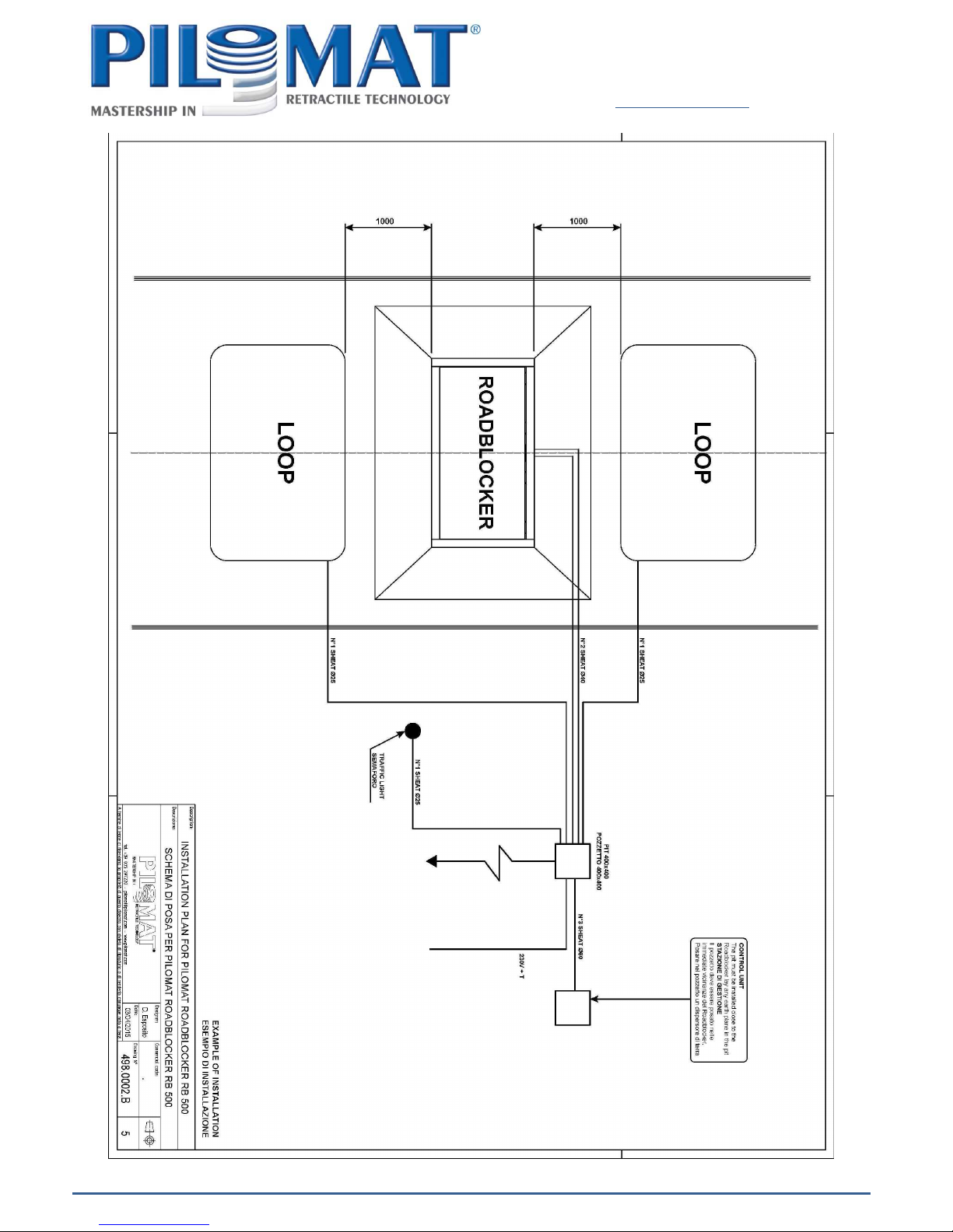
10) Lay any additional accessories and the pipes for the power lines, such as: control panel
- safety inductive loops - traffic lights - etc. (ref. drawing 498.0002.B-5 and notes on
laying inductive loops).
11)
Place and connect the control unit (see the attached procedure).
12) When the concrete has hardend test the proper operation of ROAD BLOCKER and all
additional accesories.
PS 1: All pipes must be set in full compliance with the regulations.
PS 2: The inductive loops should not be installed less than 1m far from ROAD BLOCKER to
avoid interference during the movement.
Page 7
PILOMAT Srl Unipersonale
24050 Grassobbio (BG) – Italy – Via Zanica, 17/P
Tel. +39 035 297220 – fax +39 035 297094
e-mail : [email protected] www.pilomat.com
Cod. Fisc. e Part. IVA 00383760162 – Cap. Soc. 46.800,00 i.v. R.E.A. BG n.142721 – Isc. Reg. Imp. 00383760162 A.N.C. 9549211 I.M.Q. 1301
Page 8
PILOMAT Srl Unipersonale
24050 Grassobbio (BG) – Italy – Via Zanica, 17/P
Tel. +39 035 297220 – fax +39 035 297094
e-mail : [email protected] www.pilomat.com
Cod. Fisc. e Part. IVA 00383760162 – Cap. Soc. 46.800,00 i.v. R.E.A. BG n.142721 – Isc. Reg. Imp. 00383760162 A.N.C. 9549211 I.M.Q. 1301
Page 9
PILOMAT Srl Unipersonale
24050 Grassobbio (BG) – Italy – Via Zanica, 17/P
Tel. +39 035 297220 – fax +39 035 297094
e-mail : [email protected] www.pilomat.com
Cod. Fisc. e Part. IVA 00383760162 – Cap. Soc. 46.800,00 i.v. R.E.A. BG n.142721 – Isc. Reg. Imp. 00383760162 A.N.C. 9549211 I.M.Q. 1301
Page 10
PILOMAT Srl Unipersonale
24050 Grassobbio (BG) – Italy – Via Zanica, 17/P
Tel. +39 035 297220 – fax +39 035 297094
e-mail : [email protected] www.pilomat.com
Cod. Fisc. e Part. IVA 00383760162 – Cap. Soc. 46.800,00 i.v. R.E.A. BG n.142721 – Isc. Reg. Imp. 00383760162 A.N.C. 9549211 I.M.Q. 1301
Page 11
PILOMAT Srl Unipersonale
24050 Grassobbio (BG) – Italy – Via Zanica, 17/P
Tel. +39 035 297220 – fax +39 035 297094
e-mail : [email protected] www.pilomat.com
Cod. Fisc. e Part. IVA 00383760162 – Cap. Soc. 46.800,00 i.v. R.E.A. BG n.142721 – Isc. Reg. Imp. 00383760162 A.N.C. 9549211 I.M.Q. 1301
Page 12

PILOMAT Srl Unipersonale
24050 Grassobbio (BG) – Italy – Via Zanica, 17/P
Tel. +39 035 297220 – fax +39 035 297094
e-mail : [email protected] www.pilomat.com
Cod. Fisc. e Part. IVA 00383760162 – Cap. Soc. 46.800,00 i.v. R.E.A. BG n.142721 – Isc. Reg. Imp. 00383760162 A.N.C. 9549211 I.M.Q. 1301
NOTES ON LAYING THE MAGNETIC LOOP WITH A 9,60m CABLE
When installing Road Blocker RB500, two inductive magnetic loops should be laid down to
detect metal weights (cars), one in front of the Road Blocker and another behind. The
standard dimensions of the loops are width 2,30m - length 2,50m.
Other sizes are available on request.
The loop is crafted by using a special electric cable with a diameter of approximately 9 mm
and suitable protection, laid directly in the ground without pipes.
When laying the loop, it is necessary to check the presence of electro welded metal meshes
nearby. If this is the case, it is essential that the mesh is at least 25cm below the loop
(otherwise, a 30 cm section of the mesh below the loop must be removed).
The loops should be placed 5-7 cm below the road surface. If the surrounding area is of set
stone or similar, the blocks must be lowered to allow the laying of the loops at this depth.
Alternatively, the loops could be laid between one block and another with a Greek fret
pattern.
The loop is connected to a line that sends the signal to the control unit. The line is made of
a special insensitive cable to be laid in a 25mm diameter sheath.
Page 13

PILOMAT Srl Unipersonale
24050 Grassobbio (BG) – Italy – Via Zanica, 17/P
Tel. +39 035 297220 – fax +39 035 297094
e-mail : [email protected] www.pilomat.com
Cod. Fisc. e Part. IVA 00383760162 – Cap. Soc. 46.800,00 i.v. R.E.A. BG n.142721 – Isc. Reg. Imp. 00383760162 A.N.C. 9549211 I.M.Q. 1301
CONNECTION PROCEDURE ROAD BLOCKER RB500 - CONTROL UNIT
Following the connection procedure of Road Blocker RB500 to the control unit:
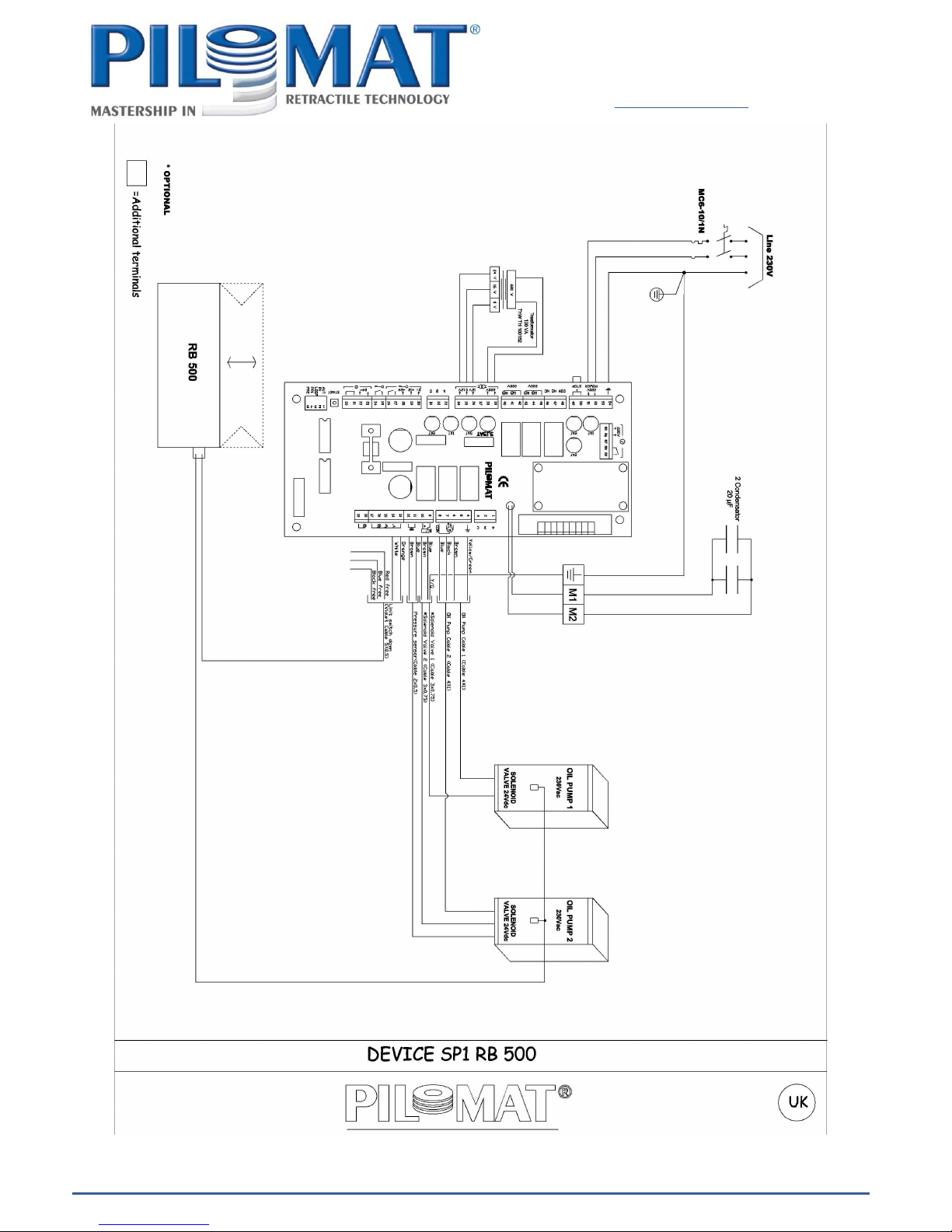
- Lay the power supply cable 230V 50/60Hz (of suitable section in relation to the length of the
line) and connect it to the safety electromagnetic switch.
- Lay the grounding and connect it to the dedicated point.
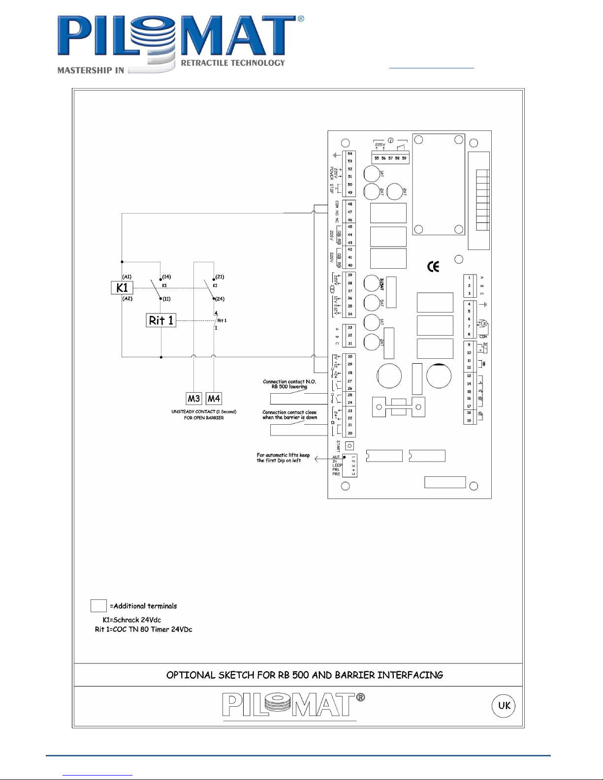
- Lay the line for console and connect it to the master (terminal 24 – 25).
- Lay the line for traffic light and connect it to the master (terminal 40 – 41 – 42).
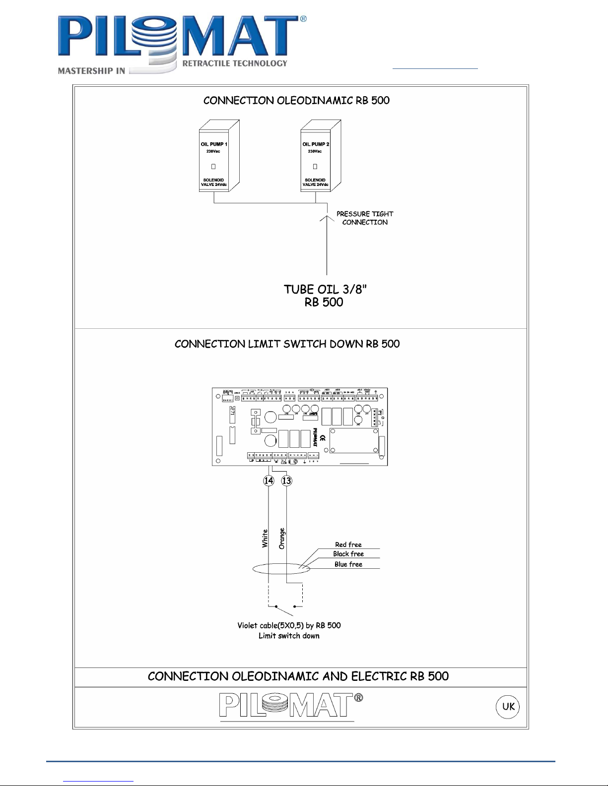
- Lay the line for Road Blocker signals and connect it to the master (terminal 13 – 14).
- Lay the black hydraulic hose and the blue moisture drainage pipe for the piston of Road
blocker.
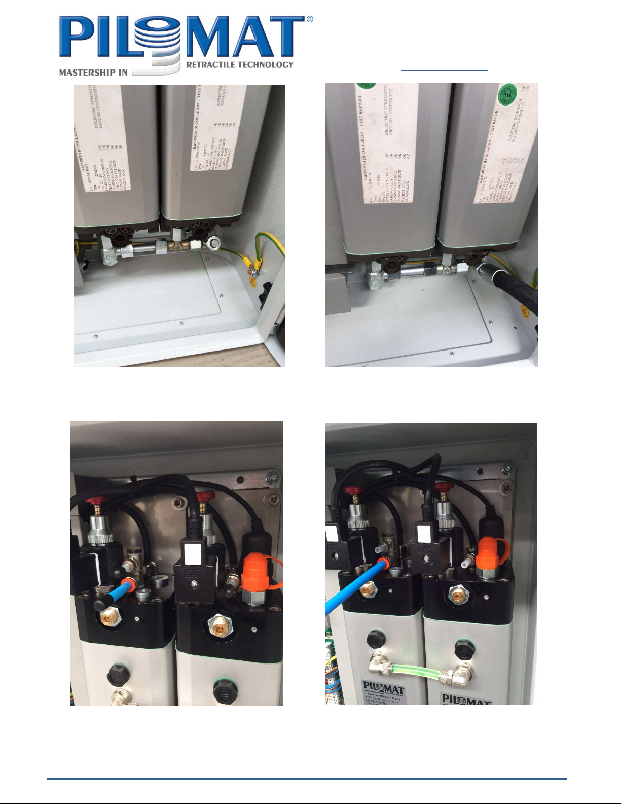
- Connect the black hydraulic hose (see picture 1-2) – warning: the hose is filled with oil so
pay attention while connecting.
- Connect the blue moisture drainage pipe (see picture 3-4) – warning: the connection is
done with a quick release; to remove the sample pipe (see picture 3), press the orange ring
nut and extract the pipe.
- Remove the two black caps (only for delivery) placed on two white vent pipe for hydraulic
pumps (see pictures 3-4).
- Execute other additional connections of the system.
- Test the proper operation of the Road Blocker.
TECHNICAL
DATASHEET OF SP CONT
ROL UNI
T RB
500
Electronic control circuit
Micro
-
processor
-operated, with dedicated
software which manages the
ROAD BLOCKER
units.
Protection class
Not less than IP
56
Operational temperature
-
40°C + 70°C
Power supply 230V One phase – 50/60HZ – 6A
Protection cut-off
Ma
gneto
-
thermic switch
1P+N
– 10A –
6KA
Standard cabinet Wall mounting - 700x500x200P mm
Page 14
PILOMAT Srl Unipersonale
24050 Grassobbio (BG) – Italy – Via Zanica, 17/P
Tel. +39 035 297220 – fax +39 035 297094
e-mail : [email protected] www.pilomat.com
Cod. Fisc. e Part. IVA 00383760162 – Cap. Soc. 46.800,00 i.v. R.E.A. BG n.142721 – Isc. Reg. Imp. 00383760162 A.N.C. 9549211 I.M.Q. 1301
PHOTO 1 PHOTO 2
PHOTO 3 PHOTO 4
Page 15
PILOMAT Srl Unipersonale
24050 Grassobbio (BG) – Italy – Via Zanica, 17/P
Tel. +39 035 297220 – fax +39 035 297094
e-mail : [email protected] www.pilomat.com
Cod. Fisc. e Part. IVA 00383760162 – Cap. Soc. 46.800,00 i.v. R.E.A. BG n.142721 – Isc. Reg. Imp. 00383760162 A.N.C. 9549211 I.M.Q. 1301
Page 16
PILOMAT Srl Unipersonale
24050 Grassobbio (BG) – Italy – Via Zanica, 17/P
Tel. +39 035 297220 – fax +39 035 297094
e-mail : [email protected] www.pilomat.com
Cod. Fisc. e Part. IVA 00383760162 – Cap. Soc. 46.800,00 i.v. R.E.A. BG n.142721 – Isc. Reg. Imp. 00383760162 A.N.C. 9549211 I.M.Q. 1301
Page 17

PILOMAT Srl Unipersonale
24050 Grassobbio (BG) – Italy – Via Zanica, 17/P
Tel. +39 035 297220 – fax +39 035 297094
e-mail : [email protected] www.pilomat.com
Cod. Fisc. e Part. IVA 00383760162 – Cap. Soc. 46.800,00 i.v. R.E.A. BG n.142721 – Isc. Reg. Imp. 00383760162 A.N.C. 9549211 I.M.Q. 1301
Page 18

PILOMAT Srl Unipersonale
24050 Grassobbio (BG) – Italy – Via Zanica, 17/P
Tel. +39 035 297220 – fax +39 035 297094
e-mail : [email protected] www.pilomat.com
Cod. Fisc. e Part. IVA 00383760162 – Cap. Soc. 46.800,00 i.v. R.E.A. BG n.142721 – Isc. Reg. Imp. 00383760162 A.N.C. 9549211 I.M.Q. 1301
Page 19
PILOMAT Srl Unipersonale
24050 Grassobbio (BG) – Italy – Via Zanica, 17/P
Tel. +39 035 297220 – fax +39 035 297094
e-mail : [email protected] www.pilomat.com
Cod. Fisc. e Part. IVA 00383760162 – Cap. Soc. 46.800,00 i.v. R.E.A. BG n.142721 – Isc. Reg. Imp. 00383760162 A.N.C. 9549211 I.M.Q. 1301
Page 20

PILOMAT Srl Unipersonale
24050 Grassobbio (BG) – Italy – Via Zanica, 17/P
Tel. +39 035 297220 – fax +39 035 297094
e-mail : [email protected] www.pilomat.com
Cod. Fisc. e Part. IVA 00383760162 – Cap. Soc. 46.800,00 i.v. R.E.A. BG n.142721 – Isc. Reg. Imp. 00383760162 A.N.C. 9549211 I.M.Q. 1301
PILOMAT ELECTRONIC CIRCUIT DIP–SWITCH FUNCTIONALITIES
Item PIL 03
FOREWORD: the DIP SWITCHES that are found on the Road Blocker electronic circuit board are
useful to the technicians for a quick diagnostic during maintenance/repair work of the system.
Indeed, in the event of failures, instead of disconnecting the wires from the terminal strips, it proves
to be more functional to cut out a part of the circuits through a proper positioning of the DIP
SWITCHES -
DIP–SWITCH IN THE OFF POSITION DIP–SWITCH IN THE ON POSITION
AUTOMATIC LIFTING ENABLED 1 AUTOMATIC LIFTING INHIBITED
DRIVES ENABLED 2 DRIVES INHIBITED
SAFETY DEVICES ENABLED 3 SAFETY DEVICES INHIBITED
LIFTING LIMIT STOP ENABLED 4 LIFTING LIMIT STOP PRESSURE
SWITCH INHIBITED
REVERSAL PRESSURE SWITCH
ENABLED
5 REVERSAL PRESSURE SWITCH
INHIBITED
DIP SWITCH 1:
Position yet to be defined as a function of the specific need and configuration of the system (if the
safety devices are not used, it MUST be positioned ON) –
Position OFF = AUTOMATIC LIFT ENABLED: the Road Blocker is normally set to be in the
high position – after the actuation of the drive, it reaches the low position – when the vehicle has
crossed the controlled passage (hence it engages and then disengages the safety devices), the
Road Blocker rises to the high position– if the vehicle does not cross the passage, the Road Blocker
moves back to the high position automatically after 30” –
Position ON = AUTOMATIC LIFT INHIBITED: the Road Blocker, after actuating the drive for
the first time, moves from high to low – then after a further actuation it moves back to the top
position –
DIP SWITCH 2:
Normally in the OFF position –
Position OFF = DRIVES ENABLED: the Road Blocker operating drives associated with
terminals 24/25 – 26/27 – 58/59 are operative –
Position ON = DRIVES INHIBITED: the Road Blocker operating drives associated with
terminals 24/25 – 26/27 – 58/59 are inhibited – if the Road Blocker does not rise, the technician, on
intervening, may temporarily inhibit the drives and use the dedicated push-button located on the
same circuit to operate some trial runs -
Page 21

PILOMAT Srl Unipersonale
24050 Grassobbio (BG) – Italy – Via Zanica, 17/P
Tel. +39 035 297220 – fax +39 035 297094
e-mail : [email protected] www.pilomat.com
Cod. Fisc. e Part. IVA 00383760162 – Cap. Soc. 46.800,00 i.v. R.E.A. BG n.142721 – Isc. Reg. Imp. 00383760162 A.N.C. 9549211 I.M.Q. 1301
DIP SWITCH 3:
Normally in the OFF position –
Position OFF = SAFETY DEVICES ENABLED: the input for safety devices, associated with
terminals 20/21, is enabled - if the dip–switch is in the OFF position and the device is not connected
(or without closing jumper), the column will not rise to the high position –
Position ON = SAFETY DEVICES INHIBITED: the input for safety devices, associated with
terminals 20/21, is inhibited – if the Road Blocker does not rise, the technician, on intervening, may
temporarily inhibit the safety devices to check whether the cause of the failure is to be ascribed to
the safety devices themselves–
DIP SWITCH 4:
Normally in the OFF position –
Position OFF = LIFTING LIMIT STOP-PRESSURE SWITCH ENABLED: at the final lifting
stage, the signal emitted by the pressure switch is used as upper limit stop to end the lifting stage -
Position ON = LIFTING LIMIT STOP-PRESSURE SWITCH INHIBITED: The above function is
inhibited; the lifting stop occurs by timeout (the timeout delay may change as a function of the
installed EPROM memory installed in the electronic managing circuit)-
DIP SWITCH 5:
Normally in the OFF position –
Position OFF = REVERSAL PRESSURE SWITCH ENABLED: during the lifting stage, in the
event of a weight exceeding 50 kg. being detected, the pressure switch signal is used as a safety
device to stop the Road Blocker and lead it back to the “low” position -
Position ON= REVERSAL PRESSURE SWITCH INHIBITED: the function described above is
inhibited – if the Road Blocker does not rise or during the rising stage it moves back with no
apparent reason, the technician, on intervening, may temporarily inhibit this function to check
whether the cause of the failure is to be ascribed to the pressure switch –
Page 22

PILOMAT Srl Unipersonale
24050 Grassobbio (BG) – Italy – Via Zanica, 17/P
Tel. +39 035 297220 – fax +39 035 297094
e-mail : [email protected] www.pilomat.com
Cod. Fisc. e Part. IVA 00383760162 – Cap. Soc. 46.800,00 i.v. R.E.A. BG n.142721 – Isc. Reg. Imp. 00383760162 A.N.C. 9549211 I.M.Q. 1301
ORDINARY ROUTINE MAINTENANCE PROCEDURE FOR
PILOMAT® ROAD BLOCKER
The standard routine maintenance sequence is as follows:
Cleaning of the inner part of Road Blocker with suction of all material settlements –
Cleaning of the water drainage tube located on the bottom of the pit Testing of the hydraulic circuit for oil leaks–
General testing the correct tightening of screw’s elements–
General cleaning of Road Blocker and painting touch-ups, if needed Testing of the hydraulic pump, top-up of oil level (if needed) and checks over working
pressure settings –
Test the multi-led flashlight incorporated in Road Blocker for proper operation
MOREOVER, IF THE FOLLOWING ITEMS ARE IN THE INSTALLATION,
PERFORM THE FOLLOWING CHECKS AND TESTS:
Test the flashlight incorporated in the element’s head for proper operation –
Operating test of traffic-lights lanterns –
Operating test of inductive safety loops –
Check over the power failure procedure for proper operation –
Operating test over the control radio receiver –
Operating test of the remote control GSM effector Sight check of the control unit management unit (e.g.: “flooded” relay contacts oxidized
clamps – etc.)
Page 23

PILOMAT Srl Unipersonale
24050 Grassobbio (BG) – Italy – Via Zanica, 17/P
Tel. +39 035 297220 – fax +39 035 297094
e-mail : [email protected] www.pilomat.com
Cod. Fisc. e Part. IVA 00383760162 – Cap. Soc. 46.800,00 i.v. R.E.A. BG n.142721 – Isc. Reg. Imp. 00383760162 A.N.C. 9549211 I.M.Q. 1301
All descriptions and pictures of this manual a re not binding. PILOMAT srl has the right, maintaining the main characteristics of its products, to provide them with needed modifications at any time and
without up-dating of this manual, in order to improve their technical performance or to meet commercial requirements.
Distributor
stamp:
 Loading...