

Page 1
BULLETIN CT-1
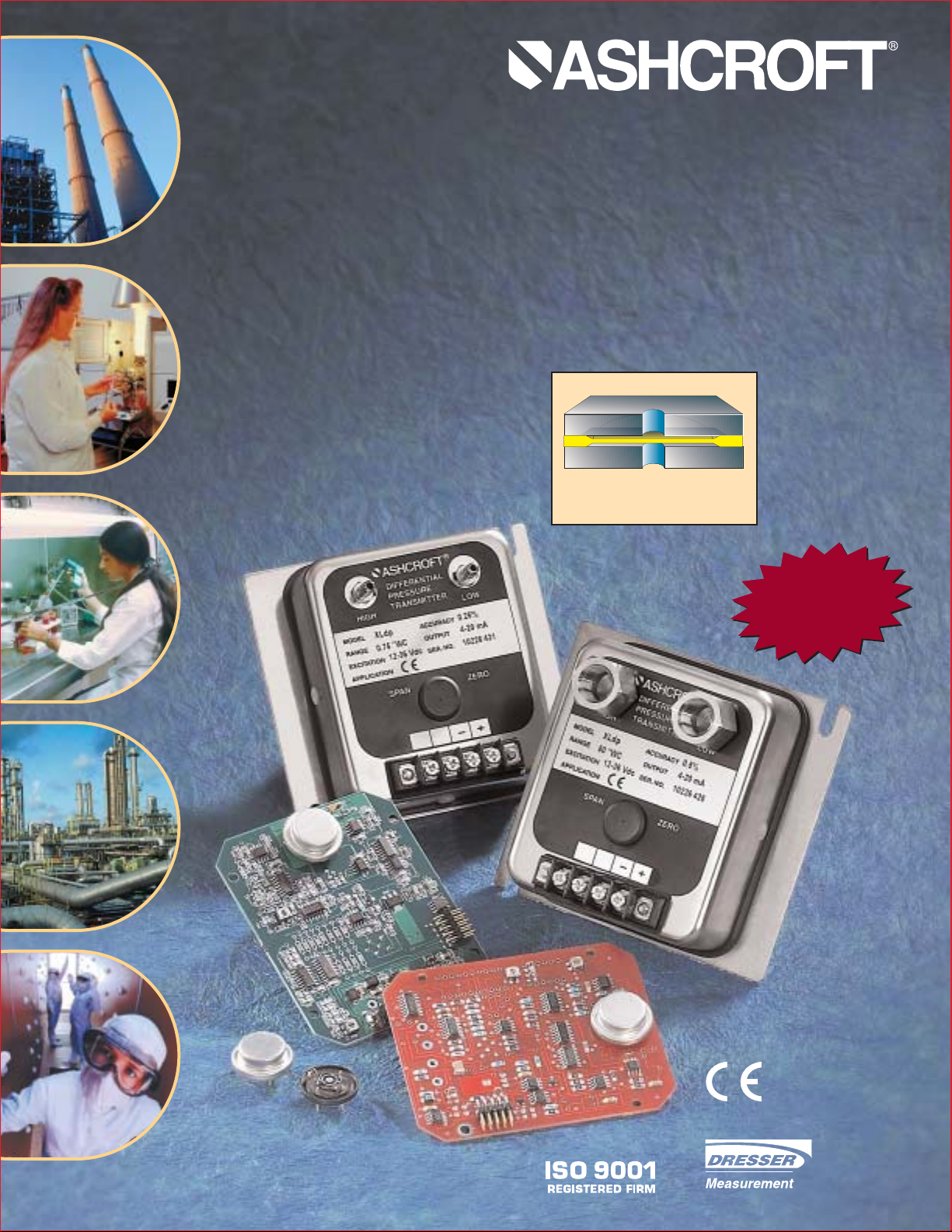
Exclusive XLdp Features Model XLdp Transmitter
Featuring a highly reliable variable
capacitance sensor using a patented
silicon glass topology. This ultra-thin
single crystal diaphragm is specifically
designed to detect to only one micron of
diaphragm deflection.
NOW WITH A
3 YEAR LIMITED
WARRANTY
APPROVED
• 10 psi proof pressure including
all pressure ranges
• Offering 0.25% accuracy down
to 0.05˝ of water column
• A wide assortment of uni- and
bi-directional ranges available
• Nonstandard ranges available
• OEM board level products
entertained
• All stainless steel NEMA 2
construction
SENSOR CROSS SECTION
The silicone diaphragm sensor has no glues
or other organics to contribute to drift or
mechanical degradation over time.
Page 2
Model XLdp Low Pressure
Differential Transducer/Transmitter
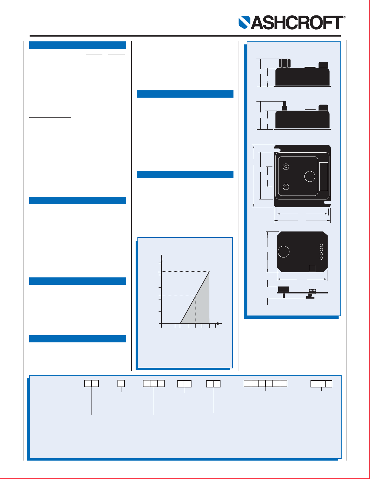
DIMENSIONS (in inches)
Load Limitations 4-20mA Output Only
V
min
= 12V+ (.022A x RL)
R
L
= RS+R
W
RL= Loop Resistance (ohms)
R
S
= Sense Resistance (ohms)
R
W
= Wire Resistance (ohms)
All specifications are subject to change without notice. All sales subject to standard terms and conditions. © Dresser Instrument, Dresser, Inc. 7/97 7.5MSP 6P 10/2001
PERFORMANCE CHARACTERISTICS
Accuracy Class (F.S.): ±0.25%
±
0.50%
Non-linearity
Terminal Point* ±0.2 ±0.4
Best Straight Line ±0.15 ±0.3
Hysteresis ±0.02 ±0.02
Non-repeatability ±0.03 ±0.05
Interchangeability ±0.25 ±0.50
*Includes hysteresis
Stability (F.S./year): ±0.5%
Standard Ranges (Inches W.C.)
Unidirectional Ranges:
Differential or Gage
0/0.1 0/1.0 0/3.0 0/25.0
0/0.25 0/1.5 0/5.0 0/50.0
0/0.5 0/2.0 0/10.0
0/0.75 0/2.5 0/15.0
Bidirectional Ranges:
Compound
±0.05 ±1.0 ±5.0
±0.1 ±2.0 ±10.0
±0.25 ±2.5 ±25.0
±0.5 ±3.0
Consult factory for non-standard ranges
Response Time: 250m sec
(Consult factory for response time options)
ENVIRONMENTAL CHARACTERISTICS
Temperature Limits:
Storage: –40 to 180°F
Operating: –20 to 160°F
(10-95% R.H. non-condensing)
Compensated Range: +35 to 135°F
Thermal Coefficients:
Zero ±0.015% F.S./°F
Span ±0.015% F.S./°F
Vibration Sweep: Less than 0.05% F.S.
temporary effect with 5g’s 0-60 Hz
EMC: CE compliant to EN61326: 1997
Annex A
FUNCTIONAL CHARACTERISTICS
Overpressure Limits:
Proof 10 psid
Burst 25 psis
Maximum static line pressure: 25 psis
Mounting Position Error:
0.5˝ W.C. and higher ≤0.10% F.S./g
0.25˝ W.C. ≤0.25% F.S./g
0.1˝ W.C. ≤0.50% F.S./g
ELECTRICAL SPECIFICATIONS
Output Signal: Power:
4-20mA* (2 wire) 12-36 Vdc
1-5 Vdc (3 wire) 12-36 Vdc
1-6 Vdc (3 wire) 12-36 Vdc
*
Optional CE versions available
How To Order
MB XL
ST
X
Type Configuration
(XLdp)
Pressure Connection
(MB2) 1⁄4 Barbed Stainless Steel
(MB8)
1
⁄8 Barbed Stainless Steel
(MB1) No Case
(FO2)
1
⁄4 NPTF
Output
Connection
(ST) Screw
Term inal
Accuracy/TC
(3) 0.25%, ±0.015%F.S./°F
(5) 0.50%, ±0.015%F.S./°F
Output Signal
(15) 1-5 Vdc
(16) 1-6 Vdc
(42) 4-20mA
(XCE)
CE compliant with
4-20mA output
(XCL)
Non-standard
calibration
Diff. or Gauge:
(P1IW) 0.10˝W.C.
(P5IW) 0.50˝W.C.
(2P5IW) 0.25˝W.C.
(7P5IW) 0.75˝W.C.
(1IW) 1.00˝W.C.
(1P5IW) 1.50˝W.C.
(2IW) 2.00˝W.C.
(2P5IW) 2.50˝W.C.
(3IW) 3.00˝W.C.
(5IW) 5.00˝W.C.
(10IW) 10.00˝W.C.
(25IW) 25.00˝W.C.
(50IW) 50.00˝W.C.
Compound:
(P05IWL) ±0.05˝W.C.
(P1IWL) ±0.10˝W.C.
(P25IWL) ±0.25˝W.C.
(P5IWL) ±0.50˝W.C.
(1IWL) ±1.00˝W.C.
(2PIWL) ±2.00˝W.C.
(2P5IWL) ±2.50˝W.C.
(3IWL) ±3.00˝W.C.
(5IWL) ±5.00˝W.C.
(10IWL) ±10.00˝W.C.
(25IWL) ±25.00˝W.C.
(50IWL) ±50.00˝W.C.
Pressure Range
Optional
X-Variations
Resolution: Infinite
Reverse Wiring Protected
Zero and Span Potentiometers: Externally
accessible, non-interactive, ±10% F.S.
adjustment.
Supply Current: <6mA for voltage output.
Warm-up Time: 10 sec. max. to meet stated
specifications
PHYSICAL CHARACTERISTICS
Pressure Connections:
1
⁄4˝ barbed stainless steel
1
⁄8˝ barbed stainless steel (optional)
1
⁄4 NPT female stainless steel (optional)
Electrical Connections: Terminal strip
Enclosure: NEMA 2
Weight: 14 oz
MATERIALS:
Case: 300 stainless steel
Media: Clean, dry, non-corrosive gas
(consult factory for use on other media).
NOT FOR USE ON LIQUIDS
OPTIONS
Pressure Connections:
• Non-standard calibration (XCL)
• CE compliant (XCE) 4-20mA only
NOTES:
• Consult factory for additional options
including pressure ranges, temperature
compensation, packaging variations and
signal response time.
Loop Resistance (Ω)
1250
1045
1000
750
545
500
250
0
0 10 12 20 24 30 36 40
Loop Supply Voltage (VDC)
OPERATING
REGION
MB3
1.98
1.29
MB2
1.9
1.3
4.6
3.3
1.7
3.9
4.2
MB1
3.00
3.70
.84
 Loading...