

Page 1

Page 2
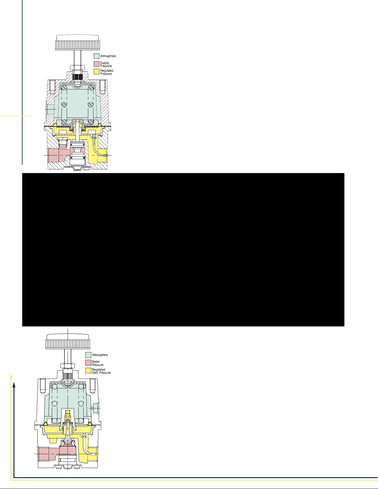
Type-70 High Flow
Air Pressure Regulator
FEATURES
• High flow capacity - Up to 80 SCFM (2266 LPM)
• Responds quickly to minute changes in downstream pressure
• Dampening action of aspirator tube maintains downstream pressure
• Balanced supply valve minimizes the effect of supply pressure changes
• Bellofram’s Buna-N and polyester rolling diaphragms are designed to
provide millions of cycles
• Honking & buzzing eliminated by action of integral baffle and aspirator tube
• Stack up construction can be disassembled and serviced without removal
from air line
DESCRIPTION
The Type-70 Regulator is specifically designed for applications that require
PRECISION CONTROL DEVICE
substantial flow capacity and accurate pressure controls. Flows of 80 SCFM
(2250 LPM) can be attained. Downstream pressure can be set within 0.25 in.
(6.3mm) of water column and is accurately maintained under varying flow conditions with the help of an aspirator tube which adjusts the air supply in accordance with the flow velocity. A balanced supply valve, utilizing a rolling
diaphragm, makes the regulator virtually immune to changes in supply
pressure.
The Type 70 has a rugged precision die-cast aluminum housing, and is pressure-tested and chromate-treated for internal
corrosion resistance. The regulator housing is finished with
vinyl paint which resists scratching, weathering and
other physical abuse.
Type-70 High Flow Back
Pressure Air Regulator
FEATURES
• High flow Capacity - Up to 50 SCFM (1400 LPM)
• Responds quickly to minute changes in upstream pressure
• Bellofram’s Buna-N and polyester rolling diaphragms are designed to give
millions of cycles
• Stack up construction can be disassembled and serviced without removal
from air line
DESCRIPTION
The Type-70 Back-Pressure Regulator functions as a high flow, high precision
pneumatic relief valve with an adjustable setpoint. The Type-70BP can be used
in place of a standard relief valve to improve pressure control while maintaining protection against over pressurization, as in supply pressure lines to instruments and other control devices.
It is most often used in conjunction with a diaphragm-operated valve and bleed
orifice as a compressor controller. Excess compressor pressure is relieved
through the regulator to actuate the intake restricting valve. When the regulator
is shut off, downstream air escapes through the bleed orifice, allowing the
restricting valve to open.
Page 3
TYPE 70 TYPE 70BP
Regulator Regulator
Sensitivity 1/4" (6.4 mm) Water Column 1/8" (3.2 mm) Water Column
Flow Capacity 40, 50, or 80 SCFM 50 SCFM
Effect of Supply Pressure variation (25 psig) < 0.025 psig (1.7 BAR) N/A
on Outlet Pressure
Exhaust Capacity (5 psig above 20 psig set point) 4 SCFM (113 LPM) N/A
Maximum Input / Supply Pressure 250 psig (17.2 BAR) 250 psig (17.2 BAR)
Effect of Changes in Flow on Regulated Pressure 2.5 psig (0.2 BAR) over flow 50 SCFM (1416 LPM) N/A
(100 psig/6.9 BAR Supply) (3/8" NPT, 0-30 psig / 0-2.1 BAR range,
Output Pressure Ranges (Type 70)
0-0.1 BAR, 0-0.7 BAR, 0-2.1 BAR, 0.1-4.1 BAR
Set Point Ranges (Type 70BP)
Total Air Consumption @ Maximum Output from 1.0 to 12.5 SCFH (0.5-6 LPM) N/A
Temperature Range -40º to 200º F (-40º to 93º C) -40º to 200º F (-40º to 93º C)
Port Size 1/4", 3/8", 1/2" NPT, BSPT 1/4", 3/8", 1/2" NPT, BSPT
Size 3.0" X 3.0" X 6.0" (76 X 76 X 152 mm) 3.0" X 3.0" X 6.0" (76 X 76 X 152 mm)
Weight 1.41 lb. (0.6 kg) 1.5 lb. (0.7 kg)
Materials of Construction Body: Diecast aluminum with vinyl paint Body: Diecast aluminum with vinyl paint
Preset Pressure No No
Tamper-Resistant Cover Yes Yes
Mounting Pipe, panel, or bracket Pipe, panel, or bracket
(1113, 1416, 2266 LPM) (1416 LPM)
15 psig / 1 BAR set point)
0-2 psig, 0-10 psig, 0- 30 psig, N/A
1-60 psig, 2-150 psig, 3-200 psig
0.1
-10.3 BAR, 0.2-13.8 BAR
N/A
0-2 psig, 0-10 psig, 0-30 psig,
0-60 psig, 0-150 psig
0-0.1 BAR, 0-0.7 BAR, 0-2.1 BAR,
0-4.1 BAR, 0-10.3 BAR
Adjusting Screw: Plated steel Adjusting Screw: Plated steel
Trim: Plated steel, brass, acetal resin Trim: Acetal, brass, plated steel, nitrile
Diaphragm: Buna-N with polyester fabric Diaphragm: Buna-N with polyester fabric
Knob: Phenolic plastic Knob: Phenolic plastic
Spring: Music wire Spring: Music wire
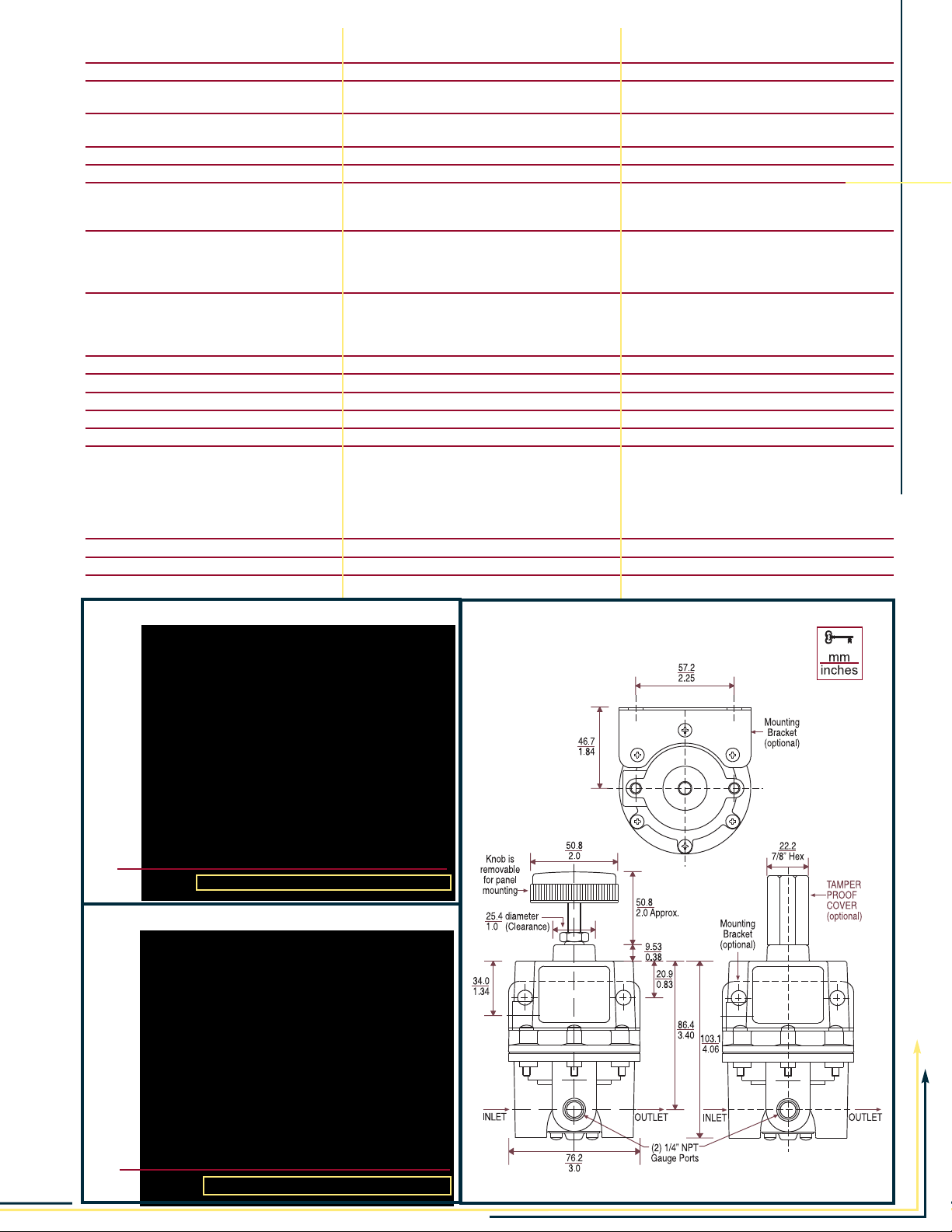
T-70 SPECIFICATIONS & DIMENSIONS
psig BAR
90 6.2
80 5.5
70 4.8
60 4.1
50 3.4
40 2.8
30 2.1
20 1.4
10 0.7
REGULATED (set) PRESSUREREGULATED (set) PRESSURE
00
SCFM 0 10.0 20.0 30.0 40.0 50.0 60.0 70.0 80.0
LPM 0 300 575 850 1150 1400 1700 2000 2265
Flow
psig BAR
90 6.2
80 5.5
70 4.8
60 4.1
50 3.4
40 2.8
30 2.1
20 1.4
10 0.7
00
SCFM 0 10.0 20.0 30.0 40.0 50.0 60.0 70.0
LPM 0 300 575 850 1150 1400 1700 2000
Flow
TYPE 70: REGULATED PRESSURE VS. FLOW
TYPE 70BP: REGULATED PRESSURE VS. FLOW
Dimensions for Type-70
& T ype-70BP
Page 4
Port
Size Set Point Range
Part Number (NPT) BAR psig
T-70
TYPE-70 HIGH FLOW REGULATORS
T-70BP
960-129-000 1/4" 0-0.1 0-2
960-174-000 3/8" 0-0.1 0-2
960-162-000 1/2" 0-0.1 0-2
960-130-000 1/4" 0-0.7 0-10
960-131-000 3/8" 0-0.7 0-10
960-163-000 1/2" 0-0.7 0-10
960-089-000 3/8" 0-2.1 0-30
960-090-000 1/4" 0-2.1 0-30
960-159-000 1/2" 0-2.1 0-30
960-091-000 3/8" 0.1-4.1 1-60
960-092-000 1/4" 0.1-4.1 1-60
960-160-000 1/2" 0.1-4.1 1-60
960-093-000 3/8" 0.1-10.3 2-150
960-094-000 1/4" 0.1-10.3 2-150
960-161-000 1/2" 0.1-10.3 2-150
960-152-000 1/4" 0.2-13.8 3-200
960-153-000 3/8" 0.2-13.8 3-200
960-164-000 1/2" 0.2-13.8 3-200
960-191-000 1/4" 0-0.1 0-2
960-192-000 3/8" 0-0.1 0-2
960-194-000 1/4" 0-0.7 0-10
960-195-000 3/8" 0-0.7 0-10
960-197-000 1/4" 0-2.1 0-30
960-198-000 3/8" 0-2.1 0-30
960-200-000 1/4" 0-4.1 0-60
960-201-000 3/8" 0-4.1 0-60
960-203-000 1/4" 0-10.3 0-150
960-204-000 3/8" 0-10.3 0-150
OPTIONS
= option is available s = standard
•
Type
2 Non-Relieving
3 Knob
Sq. Head Adj. Screw
5 Epoxy Coating
6 Tapped Vent
7 Mounting Bracket
8 Pressure Gauge
9 Tamper - Resistant Cover
10 Low Bleed
11
Check Valve •
USA EUROPE
State Route 2, Box 305 9 Castle Park, Queens Drive
Newell, WV 26050 Nottingham NG2 1AH, UK
800-727-5646 or (304) 387-1200 Tel +44 (0) 115 993 3300
FAX (304) 387-4417 Fax +44 (0) 115 993 3301
70 70BP
•
ss
••
••
•
••
••
••
•
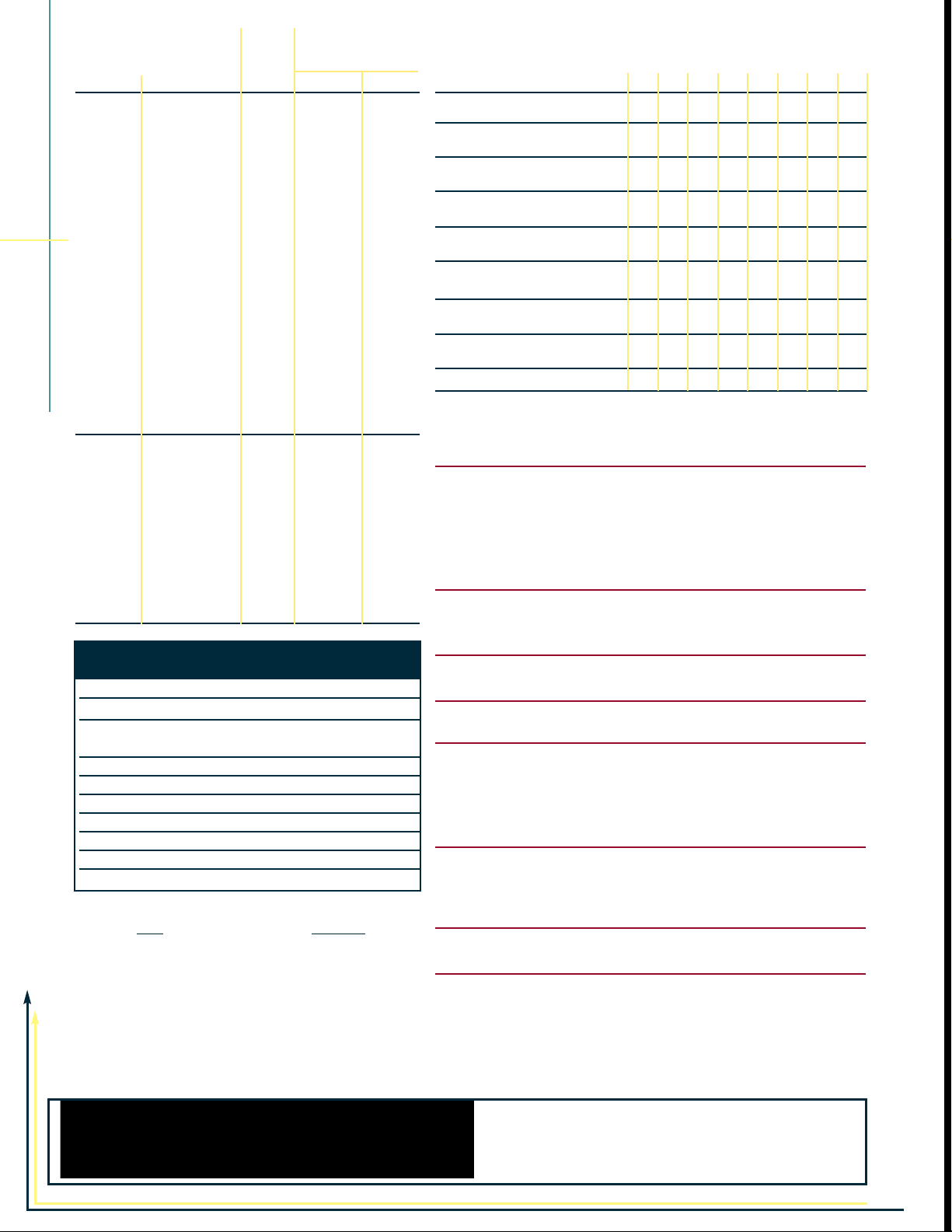
OPTION ORDERING MATRIX:
Add three digits from table below to end of part number.
OPTION 2 3 5 6 7 8 9 10 11
2 Non-Relieving 002 032 052 062 072 082 092 112
3 Sq. head Adj. Screw 003 053 063 073 083 103 113
5 Epoxy Coating 005 065 075 085 095 105 115
6 Tapped Vent 006 076 086 096 106 116
7 Mounting Bracket 007 087 097 107 117
8 Pressure Gauge 008 098 108 118
9 Tamper-Resistant Cover
10 Low Bleed 010 110
11 Check Valve 011
009 109 119
REGULATOR OPTIONS &
ACCESSORIES
NON-RELIEVING
Used in applications where it is desirable to relieve pressure
downstream of the regulator, for some constant flow applications, and where the gas flowing through the regulator must not
escape at the regulator. Non-relieving regulators should not be
used for low or no flow applications.
CORROSIVE RESISTANT EPOXY FINISH
An epoxy paint applied to the body and dripwell of the regulator
exterior surfaces to provide increased corrosion resistance.
TAPPED VENT
Allows installation of plumbing to capture exhaust air.
MOUNTING BRACKET
Steel (dichromate finish) bracket for side mounting.
PRESSURE GAUGE
Dual scale 2 in. (50.8 mm) gauges. Ranges include 0-30 psig
(0-200 kPa), 0-60 psig (0-400 kPa), 0-100 psig (0-700 kPa) and
0-160 psig (0-1100 kPa). When specified with regulator, the
correct range will be supplied.
TAMPER-RESISTANT COVER
An aluminum tubular cover placed over a slotted head adjusting
screw and screwed onto the bonnet of the regulator with a
wrench. Prevents ordinary hand adjustments.
LOW BLEED
Reduces steady-state air consumption by approximately 50%.
CHECK VALVE
Allows quick dumping of output line pressure through the
supply air line when the supply is shut down.
IMPORTANT NOTICE: Our recommendations, if any, for the use of this product are based on tests believed to be reliable. The greatest care is exercised in the selection of our raw materials and in our manufacturer, no guarantee or warranty, express or implied, is made as to such use or effects incidental to such use, handling or possession or the
results to be obtained, whether in accordance with the directions or claimed so to be. The manufacturing expressly
disclaims responsibility therefor. Furthermore, nothing contained herein shall be construed as a recommendation to
use any product in conflict with existing laws and/or patents covering any material use.
LT0805 3m 2/04
SALES & APPLICATIONS
(800) 727-5646 fax: (304) 387-4417
www.marshbellofram.com
 Loading...