

Page 1
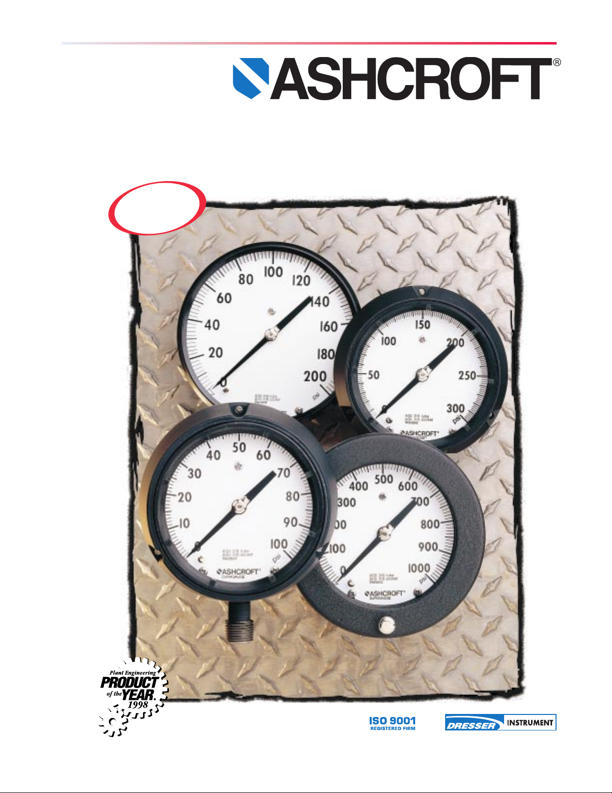
Duragauge®Pressure
Gauge
BULLETIN DU-1
a Halliburton company
PLUS!
Performance
NOW WITH
Page 2
Features & Benefits
Ashcroft®Duragauge®Pressure Gauge
The Ashcroft®Duragauge®pressure
gauge is the finest production gauge on
the market for industrial use where precise indications are required. The product line offers a wide v ariety of case
styles, Bourdon tubes and pressure
ranges to meet your application needs .
With the component combinations
available in the Dur agauge gauge line ,
over ten million variations are possib le
to serve the needs of all types of industries, including process, power , n uclear,
aerospace and cryogenics.
The Duragauge gauge offers the
same outstanding quality and craftsmanship which have characterized all
Ashcroft products since Edward
Ashcroft introduced the Bourdon tube
pressure gauge to American industry in
1852. It is built for long lif e and sustained accuracy under the most
adverse operating conditions.
Uncompromising standards have
been established for all incoming materials used in Ashcroft products, with
dimensional details, material selection
and design carefully scrutinized. Tubing
used in manufacturing Bourdon tubes
must meet stringent standards, more
restrictive than ASTM material specifications. Throughout production, quality
assurance procedures are adhered to,
including assembly inspection, and critical laboratory examination.
Product integrity is assured through
continual monitoring of pressure element quality. Every Bourdon tube system is subjected to a leak test at a pressure above the top of its range . Computer programs yield Bourdon tube
designs with minimum stresses, assuring the long life and sustained accuracy
demanded of Ashcroft products.
In the engineering breakdown lab, a
variety of tests are run continually on
Duragauge Bourdon tube systems,
such as pulsation, burst, vibration, wear,
and friction tests on movements.
Care and attention are given to ev ery
product from its inception to final
assembly. The end result- thoroughly
engineered instruments that assure the
user a product that is precise, dependable and durable.
Ashcroft has pioneered the field of
gauge manufacture in research and
product integrity since the Bourdon tube
was introduced to American industry .
The list of Ashcroft “firsts” in pressure
gauge development would fill several
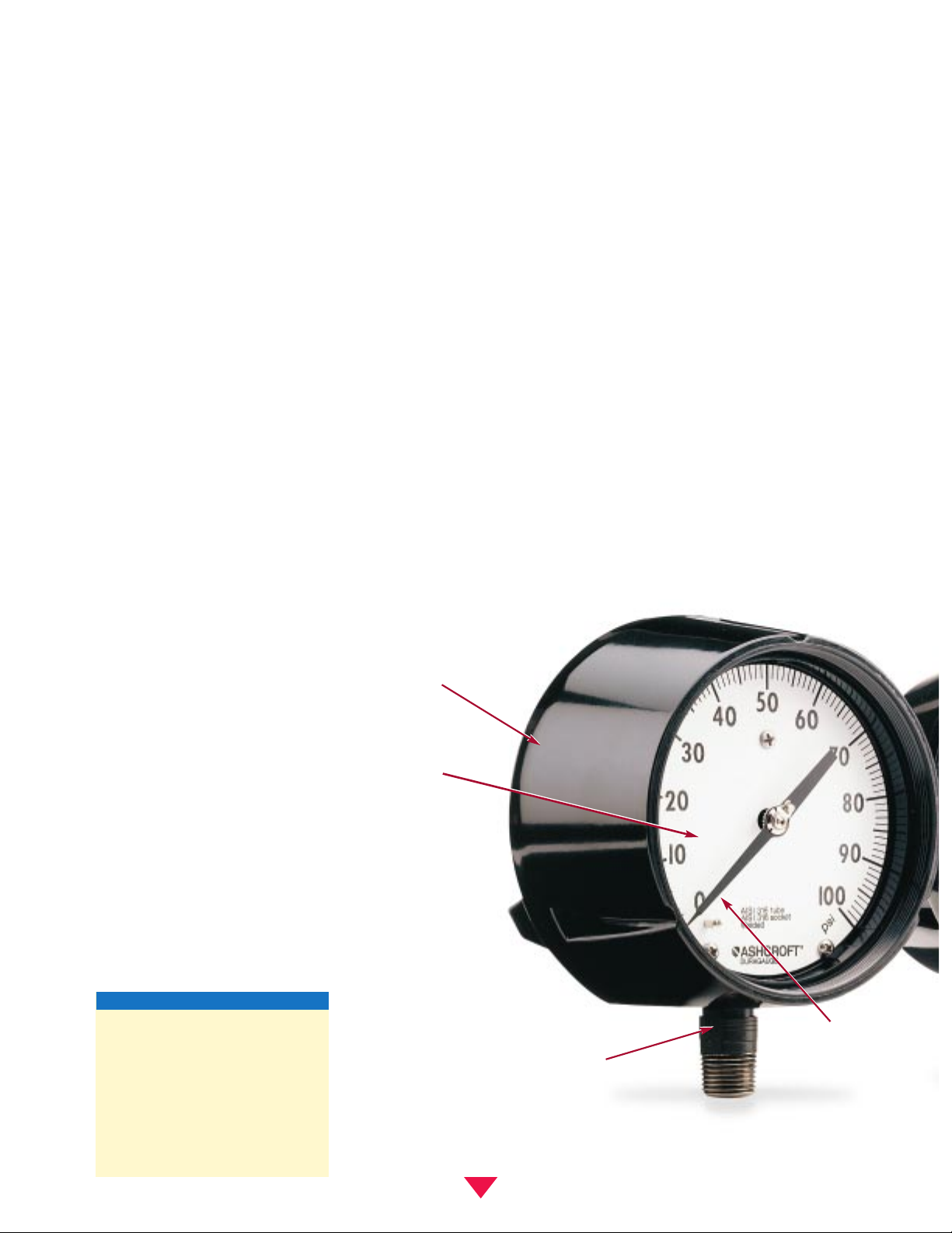
Solid front case design, field
convertible to hermetically
sealed or liquid filled style
Pressure ranges from
vacuum-100,000 psi
Micrometer adjusta
pointer
Select from various
socket and Bourdon
tube materials
CONTENTS
Page
2 & 3 Features and benefits
4 Warranty and movement
5 Other Duragauges
6 & 7 Specification matrix
8 Product selection information
9 Media application table
10 & 11 Range tables
12 Options
13 How to order
14 & 15 Dimensions
2
Page 3
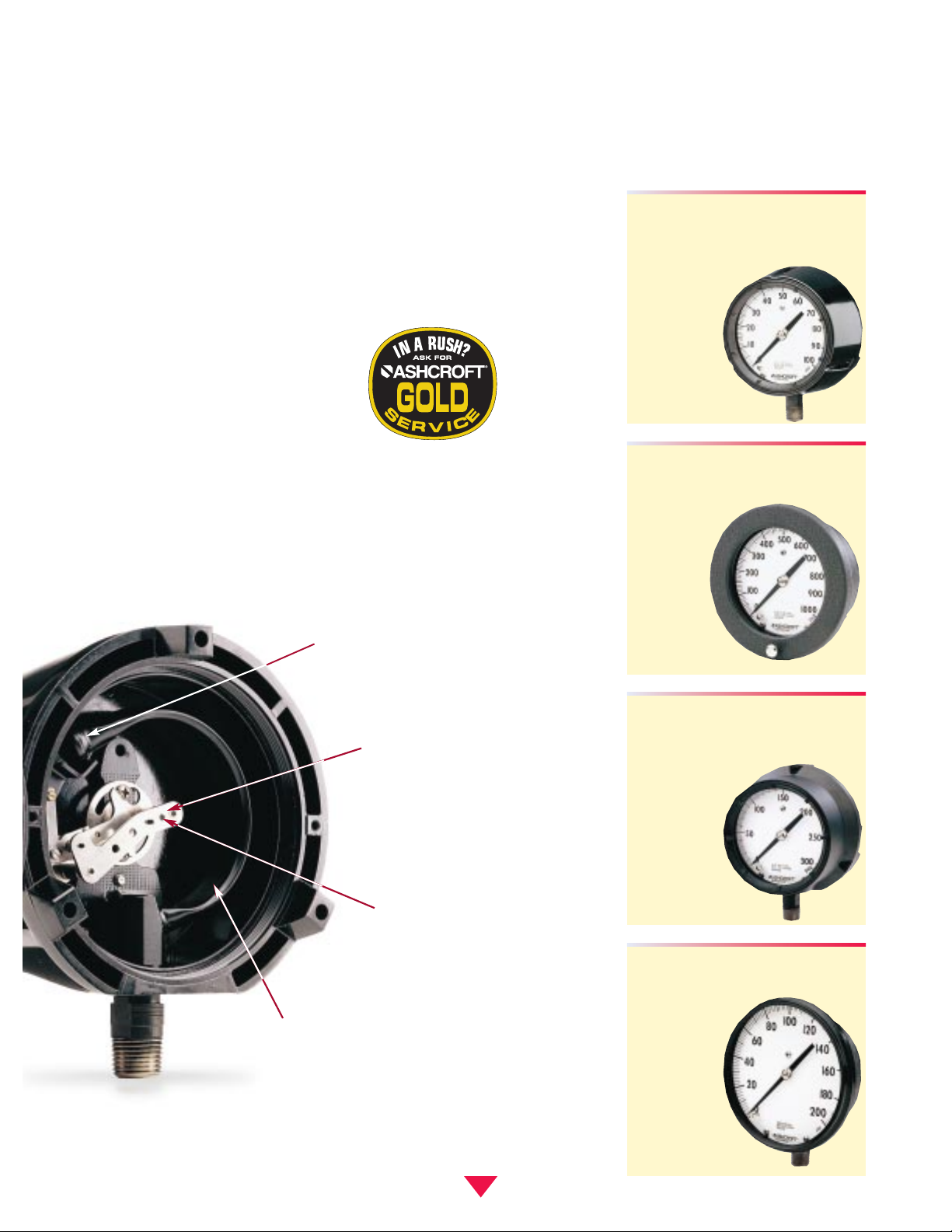
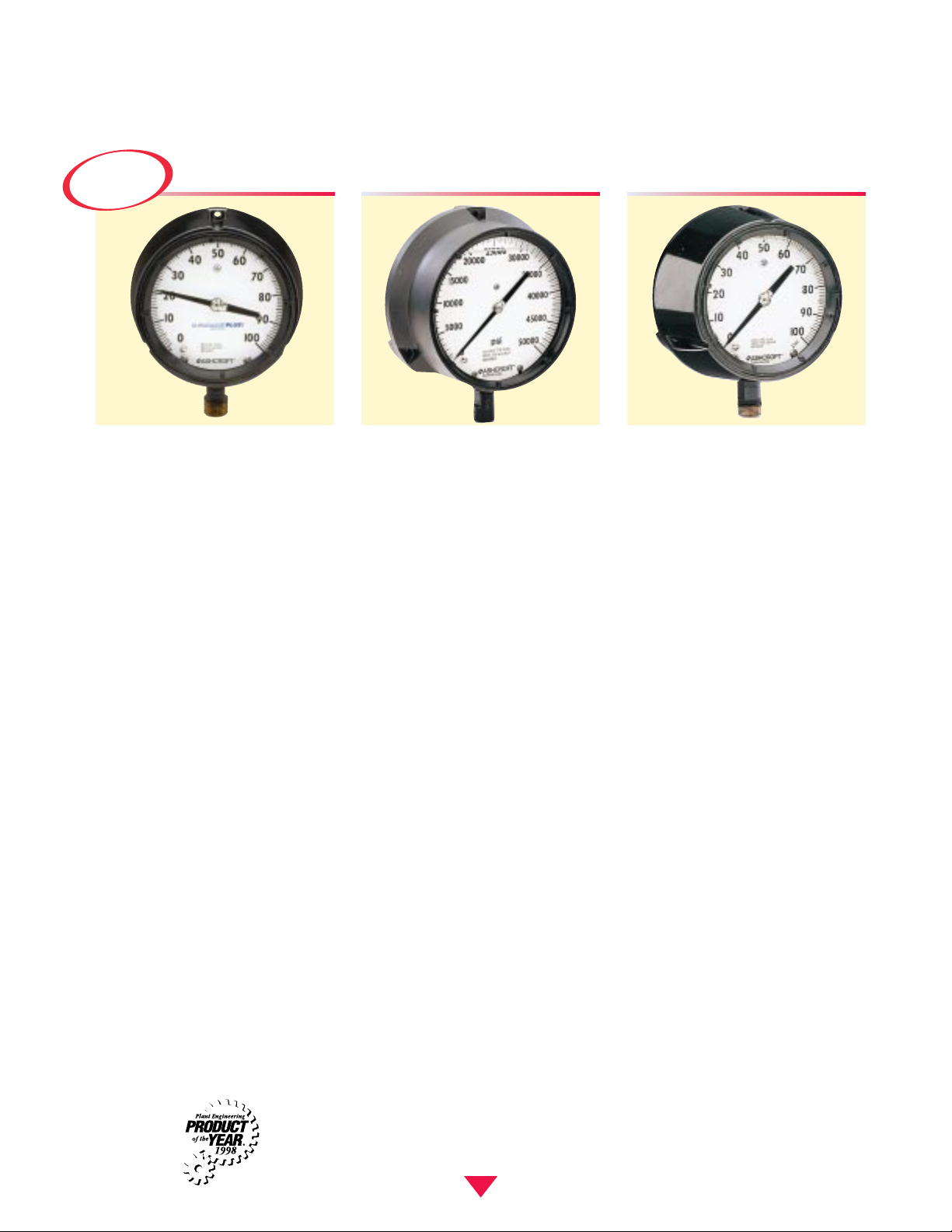
1379 Case style
Available in 41⁄
2˝ 6,˝ and 8
1
⁄
2˝ sizes. The
Ashcroft model 1379 solid front gauge
has a black epoxy coated alumin um case
with a threaded reinforce polypropylene ring. This
weather-proof
gauge can be
converted to
liquid filled or
hermetically
sealed using a
conversion kit.
1377 Case style
Designed particularly for flush mounting,
the Ashcroft model 1377 is available in
4
1
⁄
2,˝ 6,˝ and 8
1
⁄
2˝ dial
sizes. The
hinged steel
black wrinkle
enamel
coated ring
makes this
gauge well
suited for panel
board applications.
1279 Case style
The Ashcroft solid front phenolic case
1279 gauge can be converted to hermetically sealed or liquid filled using a conversion kit. Availab le in
4
1
⁄
2˝ dial size this
gauge has a
threaded reinforced polypropylene front
ring for easy
zero adjustment
with a micrometer
adjustable pointer.
pages. They include the rotary geared
stainless steel movement, the all 316
stainless steel pressure system, the
phenolic turret case, numerous other
improvements and most recently, the
patent pending Duragauge
®
PLUS!
.
Several important variables must be
considered when selecting the type of
case for the application. A gauge is subject to environmental and atmospheric
conditions, and the gauge internals
must be protected from these elements.
To protect the gauge from environmental and atmospheric conditions, the
1279, 1377 and 1379 Duragauges are
offered with a standard weatherproof
type case. A 4
1
⁄
2˝ 1279 and 4
1
⁄
2˝ or 6˝
1379 Duragauge can be ordered dry ,
hermetically sealed, liquid filled or with
PLUS!
performance.
400 Series stainless
steel movement wears
better for longer life
Round-Cap-Tip
construction lowers
stresses for longer life
Exclusive Features!
Teflon-coated pinion
for longer life
le
Patented Duratube™ with
welded-tube construction
controls stresses for longer life
2462 Case style
This high impact resistant polypropylene
case gauge and bayonet
lock black ring is
available with
a 6˝ dial. This
Duragauge
can be stem,
surface, or
flush mounted
and stands up
well in most
environments.
3
Page 4
Edward Ashcroft introduced the Bourdon tube
pressure gauge to American Industry 140 years
ago. Since that time, we ha ve developed thousands of improvements and ov er a hundred
patents furthering the development of Ashcroft
pressure instruments. From the v ery beginning,
we have maintained our reputation for quality ,
product performance, and technical innovation
that is the envy of all others in the industry. We
are confident of our manufacturing processes
and the design of our pressure gauge systems.
So confident, that we guarantee the Duragauge
pressure system to be free of leaks for 10 years
when installed and operated with the recommendations outlined in ASME B40.1 Of course our
standard 1 year warranty on materials, workmanship, and all other parts, is still in effect.
Millions of Ashcroft Duragauge pressure
gauges continue to deliver prov en perf ormance
in critical process applications throughout the
world. You can depend on our commitment to
quality – just what you’ve come to e xpect from
the leader in pressure technology – the people
who design, produce, and sell Ashcroft products.
For a copy of our w arranty call or write:
Dresser Instrument Division
250 East Main Street
Stratford, CT 06614-5145
203-378-8281
Ask for Customer
Service.
Warranty & Movement
Ashcroft®Duragauge®Pressure Gauge
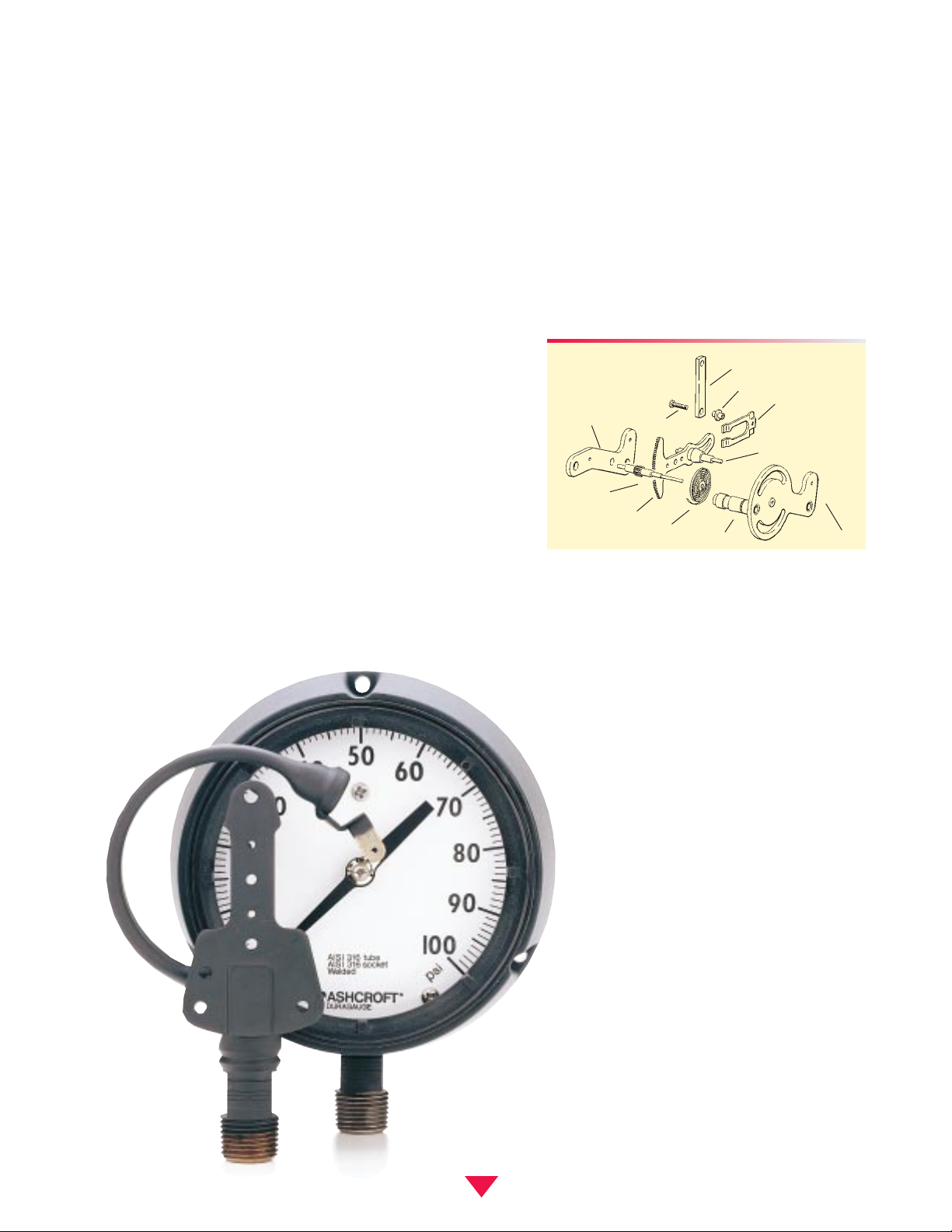
The Ashcroft®Stainless Steel Rotary Geared
Teflon
®
S Movement is another “first” in gauge
manufacture. It is truly innov ativ e with its thinner
plates and segment, elimination of bushings,
and low friction Teflon S coating on wearing
parts. The shock resistance and stability of the
Duragauge movement has been enhanced b y
staking the movement top and bottom plates.
A Teflon S coating
is applied to the pinion gear, pinion
shaft, link screws
and segment shaft.
These critical components translate
the motion of the
Bourdon tube tip
into the rotating
pointer motion.
Minimal friction is
essential for
reduced wear.
The coating also serves to protect wear surfaces
from outside ambient conditions.
A specially formulated lubricant is applied to all
wear points. Wear is further reduced because
the moving parts are light weight. The curved tail
segment provides easy calibration by mini-
mizing the effect of the span adjust-
ment on zero.
LINK SCREW
CAPTIVE NUT
SEGMENT SHAFT
TOP PLATE
PINION
SEGMENT
HAIR SPRING
PILLAR
BOTTOMPLATE
LINK
BUSHING
Stainless steel rotary
geared Teflon®coated
movement
4
Teflon®– DuPont Trademark
Page 5
PLUS!
™
Performance Dura gauge
®
An exclusive, ne w, optional feature
provides virtually liquid-filled performance in a dry gauge.
The Ashcroft
PLUS!
™
feature is a
patent-pending design incorporated into
the industry-standard Ashcroft pressure
gauge.
PLUS!
is available in an y Dura-
gauge case style material or range.
Historically , pulsation and vibr ation
have reduced gauge lif e and made
gauges difficult to read.
Customers have had no alternative to
liquid-filled gauges to solve vibration
and pulsation problems, until now!
Advantages V er sus
Liquid-Filled Gauges
• Saves mone y
- Lower purchase price versus liquidfilled gauges
- Eliminates costly specialty fills
- Allows easy standardization to
reduce mis-applications
• Eliminates possibility of leaks
• Lighter weight . . . easier to handle
• Eliminates liquid-fill lines . . .
easier to read
• Easy recalibration
• Wider ambient temperature range
than glycerin
• Eliminates disposal and environmental issues
Advantages V er sus Dry Gauges
• Steady pointer . . . same as liquidfilled gauges
• 100% longer life gauges . . .
reduces gauge usage 50%!
Other Duragauges
Ashcroft®Duragauge®Pressure Gauge
High Pressure Duragauge
®
The Ashcroft high pressure Duragauge has a helical wound Inconel
Bourdon tube which is capable of withstanding vibration without a zero shift or
change in calibration. Because of the
length of the helical tube, stresses are
minimized and the tip trav el increased;
this permits the use of a low ratio movement, which decreases wear from friction and increases gauge life. F or use
on high pressure test applications, metal
and concrete water cutting equipment,
and other high pressure applications.
Features of the gauge include ASME
B40.1, grade 2A,
1
⁄
2 of 1% full scale, 6˝
dial, lower or back connection, solid
front aluminum case for wall or flush
mounting. Inconel 718 Bourdon tube
and 316 stainless steel socket is standard. A hermetically sealed, field liquidfillable case is standard. The Ashcroft
high pressure Duragauge is availab le in
ranges of 50,000 psi, 80,000 psi, and
100,000 psi with a standard
1
⁄
4˝ high
pressure tubing connection.
Receiver Duragauge
®
Used in conjunction with pneumatic
transmitters, Ashcroft receiver gauges
indicate pressure, temperature, flow, or
any information that can be transmitted
by proportional variations in air pressure.
For information concerning other receiver gauges offered, consult Customer
Service, Stratford, Connecticut.
Liquid-Filled Duragauge
®
Liquid-filled Duragauges have tr aditionally been used in applications where
there is excessive vibration and pulsa tion. Vibration can cause rapid movement resulting in loss of accuracy and
possibly complete destruction of the
gearing. Pulsation can generate millions of pressure cycles causing Bourdon tube fatigue and reduced service
life. The field conversion kit contains an
Ashcroft patented elastomeric back
which provides compensation for ambient temperature variation while providing all the features of a blo w-out bac k.
The sealed case completely excludes
dusty or corrosive environmental conditions. Since vibration and pulsation frequently occur together, all liquid filled
Duragauges are fitted with a throttle
plug screwed into the sock et. This can
easily be removed or changed f or viscous or particulate containing media.
Seven sizes are a vailable from .006 to
.070 diameter.
5
PLUS!
Performance
Page 6
Specification Matrix
Ashcroft®Duragauge
®
Pressure Gauges
6
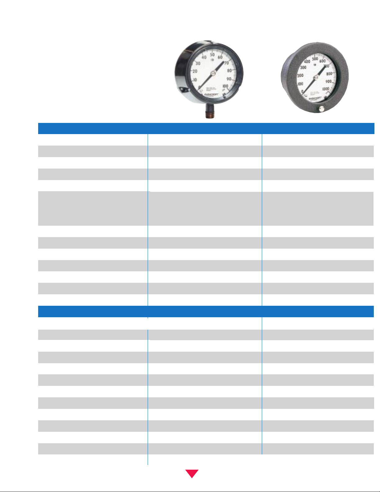
Specifications Code Type 1279 Type 1377
Accuracy (ASME B40.1, Grade 2A)
1
⁄
2% Full Scale
1
⁄
2% Full Scale
Case material Black phenolic Aluminum, black epoxy coated
Dial size (45), (60), (85) 41⁄
2,˝ (45) 4
1
⁄
2,˝ (45), 6,˝ (60), 8
1
⁄
2,˝ (85)
Ring type Threaded reinforced black polypropylene Steel hinged, black enamel finish
Bourdon tube/Socket material (Code)
C510 Phos. bronze/Brass brazed (A)
316L stainless steel/steel (R)
316L stainless steel/316L stainless steel (S)
K Monel/ Monel (P)
C510 Phos. bronze/Brass brazed (A)
316L stainless steel/steel (R)
316L stainless steel/316L stainless steel (S)
K Monel/ Monel (P)
Range limits (psi) Vacuum – 30,000 Vacuum – 30,000
Connection size (NPT) (02), (04), (09)
1
⁄
4 NPT (02 optional),
1
⁄
2 NPT (04 standard)
1
⁄
4 NPT (02 optional),
1
⁄
2 NPT (04 standard)
Connection location (L), (B) Lower (L), back, (B) Lower (L), back, (B)
Mounting Stem, flush, surface Stem, flush
Movement
Rotary, 400 st. st., Teflon®coated pinion gear and segment Rotary, 400 st. st., Teflon®coated pinion gear and segment
Pointer Micrometer adjustable Micrometer adjustable
Options
Glycerin fill (L)
Standard N/A
Silicone fill (XGV) Available N/A
Halocarbon fill (XGX) Available N/A
Hermetically sealed (H) Available N/A
Flush mounting ring (X56) Available Standard
Surface mounting bracket (XBF) N/A N/A
Flush mounting bracket (XBQ) N/A N/A
Duragauge®receiver gauge (XPR) Available Available
Shatterproof glass (XSG) Available Available
Acrylic window (XPD) Available Available
Set hand (red, single, fixed) (XSH) Available Available
Maximum pointer (red) (XEP) Available Available
Window Glass Glass
Case style (S) Solid front (S) Solid front (S)
PLUS!
Performance (XLL) Available Available
–50°F to +250°F
–45°C to +250°C
–40°F to +250°F
–40°C to +120°C
0°F to +250°F
–18°C to +120°C
Page 7
7
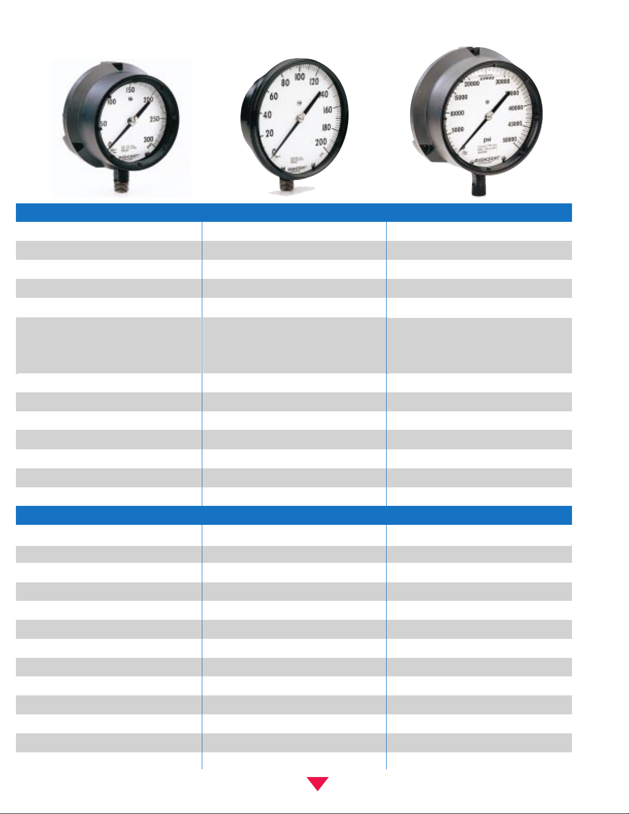
Type 1379 Type 2462 Type 1379 High pressure
1
⁄
2% Full Scale
1
⁄
2 % Full Scale
1
⁄
2% Full Scale
Aluminum, black epoxy coated Black polypropylene Aluminum, black epoxy coated
41⁄
2,˝ (45,) 6,˝ (60), 8
1
⁄
2,˝
(1)
(85) 6,˝ (60) 6,˝ (60)
Threaded reinforced black polypropylene
(2)
Bayonet lock black polypropylene Threaded reinforced black polypropylene
Inconel 718
(WW)
50,000, 80,000, 100,000
1
⁄
4 NPT (02 optional),
1
⁄
2 NPT (04 standard)
1
⁄
4 NPT (02 optional),
1
⁄
2 NPT (04 standard)
1
⁄
4˝ High pressure (09 standard)
Lower (L), back, (B) Lower (L), back, (B) Lower (L), back, (B)
Stem, flush, surface Stem, flush, surface Flush, surface
otary, 400 st. st., Teflon®coated pinion gear and segment Rotary, 400 st. st., Teflon®coated pinion gear and segment Rotary, 400 st. st., Teflon®coated pinion gear and segment
Micrometer adjustable Micrometer adjustable Micrometer adjustable
Standard N/A Available
Available N/A Available
Available N/A Available
Available N/A Standard
Available N/A Available
Available Available N/A
N/A Available N/A
Available Available N/A
Available Available Available
Available Available Standard
Available Available Available
Available Available Available
Available Available Available
Glass Glass Acrylic
Solid front (S) Solid front (S) Solid front (S)
316 stainless steel
(1) Non-liquid fillable (2) Steel hinged, black enamel finish for 81⁄
2˝ case
C510 Phos. bronze/Brass brazed (A)
316L stainless steel/steel (R)
316L stainless steel/316L stainless steel (S)
K Monel/ Monel (P)
C510 Phos. bronze/Brass brazed (A)
316L stainless steel/steel (R)
316L stainless steel/316L stainless steel (S)
K Monel/ Monel (P)
Vacuum – 30,000 Vacuum – 30,000
Page 8
Product Selection Information
Ashcroft®Duragauge®Pressure Gauge
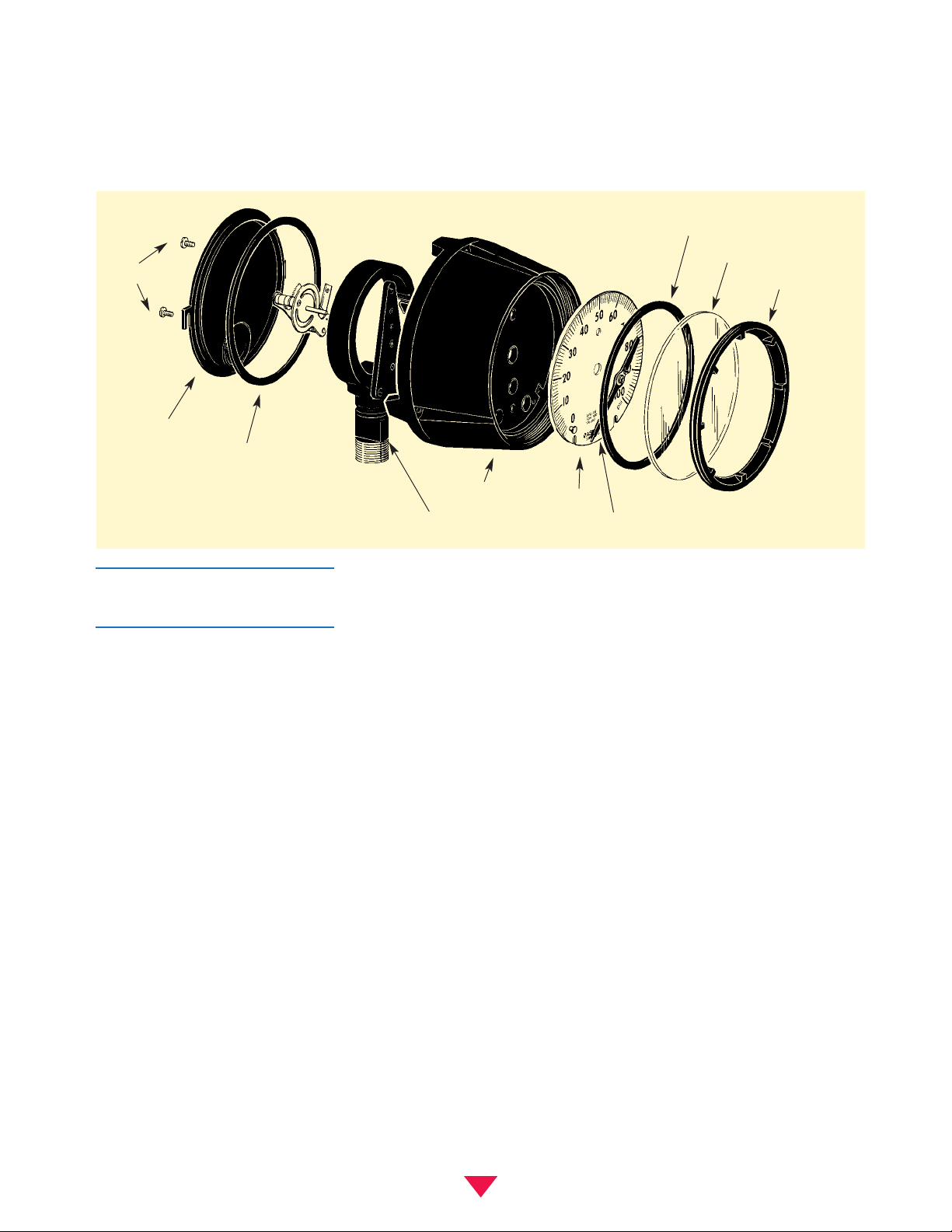
Rear Cover
Gasket
1279 Case used for illustration purposes
Screws
Bourdon Tube System
Phenol Case
Dial
Micrometer Pointer
Threaded Ring
Window
Gasket
Consult ASME B40.1 for guidance in
gauge selection
WARNING:
To prevent misapplication,
pressure gauges should be selected
considering media and ambient operating conditions. Improper application can
be detrimental to the gauge, causing
failure and possible personal injury or
property damage. The information contained in this catalog is offered as a
guide to assist in making the proper
selection of a pressure gauge. Additional information is availab le from Dresser
Instrument Division.
Pressure Ranges:
As recommended by ASME B40.1,
select a gauge with a full scale pressure
range of approximately twice the normal operating pressure. The maximum
operating pressure should not exceed
approximately 75% of the full scale
range. F ailure to select a gauge r ange
within these criteria may ultimately result in fatigue failure of the Bourdon tube .
Operating Conditions:
The operating conditions to which a
gauge will be subjected must be considered. If the gauge will be subjected
to severe vibrations or pressure pulsa tion, liquid-filling the gauge or the
PLUS!
option may be necessary to
obtain normal product life. Other than
discoloration of the dial and hardening
of the gasketing that may occur as
ambient temperatures exceed 150°F,
non liquid-filled Type 1279 (phenolic
case), 1377 and 1379 (aluminum case)
Duragauges with standard glass windows, can withstand continuous operating temperatures up to 250°F. Liquidfilled gauges can withstand 200°F but
glycerin fill and acrylic window will tend
to yellow. Accuracy will be affected by
approximately 1.5% per 100°F. Gauges
with welded joints will withstand 750°F
(450°F with silver brazed joints) f or
short times without rupture, although
other parts of the gauge will be
destroyed and calibration will be lost.
Proper selection of the Bourdon system
material is dependent on the process
fluid to which the system will be subjected. If the correct material is not available, the use of a diaphragm seal ma y
be necessary to protect the system
from the process fluid. Liquid-filled
gauges are recommended for the discharge side of positive displacement
pumps.
Pressure Elements:
Available in a wide variety of materials,
including: phosphor bronze, alloy steel,
316 stainless steel, K Monel and Inconel.
Cases:
Four solid front case types are off ered.
Solid front cases have a solid wall
between the Bourdon tube and the window . The 1279 and 1379 Duragauge
cases are field convertible by means of
a kit. These gauges can be converted
to hermetically sealed or liquid-filled.
Buna-N seals at the front and rear of
the case provide resistance to aggressive atmospheres.
Rings:
The ring, which retains the window, is
threaded, bayonet (cam), or hinged,
depending upon case type.
Movements:
Movements are designed and materials
of construction selected to reduce friction
and extend wear lif e. The Dur agauge’s
stainless steel movement is a rotary
geared design with Teflon coated wear
parts.
Dials:
Dials are uniformly graduated and hav e
highly legible black markings. A pointer
dial stop pin at the 7:00 o’clock position
is standard.
Windows:
The standard is glass on dry gauges
and acrylic on liquid-filled gauges.
Options are laminated safety glass,
non-glare glass or acrylic.
Pointer s:
Duragauge pressure gauges have balanced micrometer adjustable pointers
which can be repositioned without
removal from the pinion shaft.
8
Viton,®T eflon,®Kalrez,®Kynar®– DuPont Trademark
Carpenter 20
®
– Carpenter Steel Trademark
Inconel,
®
Monel®– Huntington Alloys Inc. Trademark
Hastelloy – Cabot Corp. Trademark
Nickel
®
– International Nickel Co., Inc. Trademark
Halocarbon
®
– Halocarbon Products Co. Trademark
Page 9
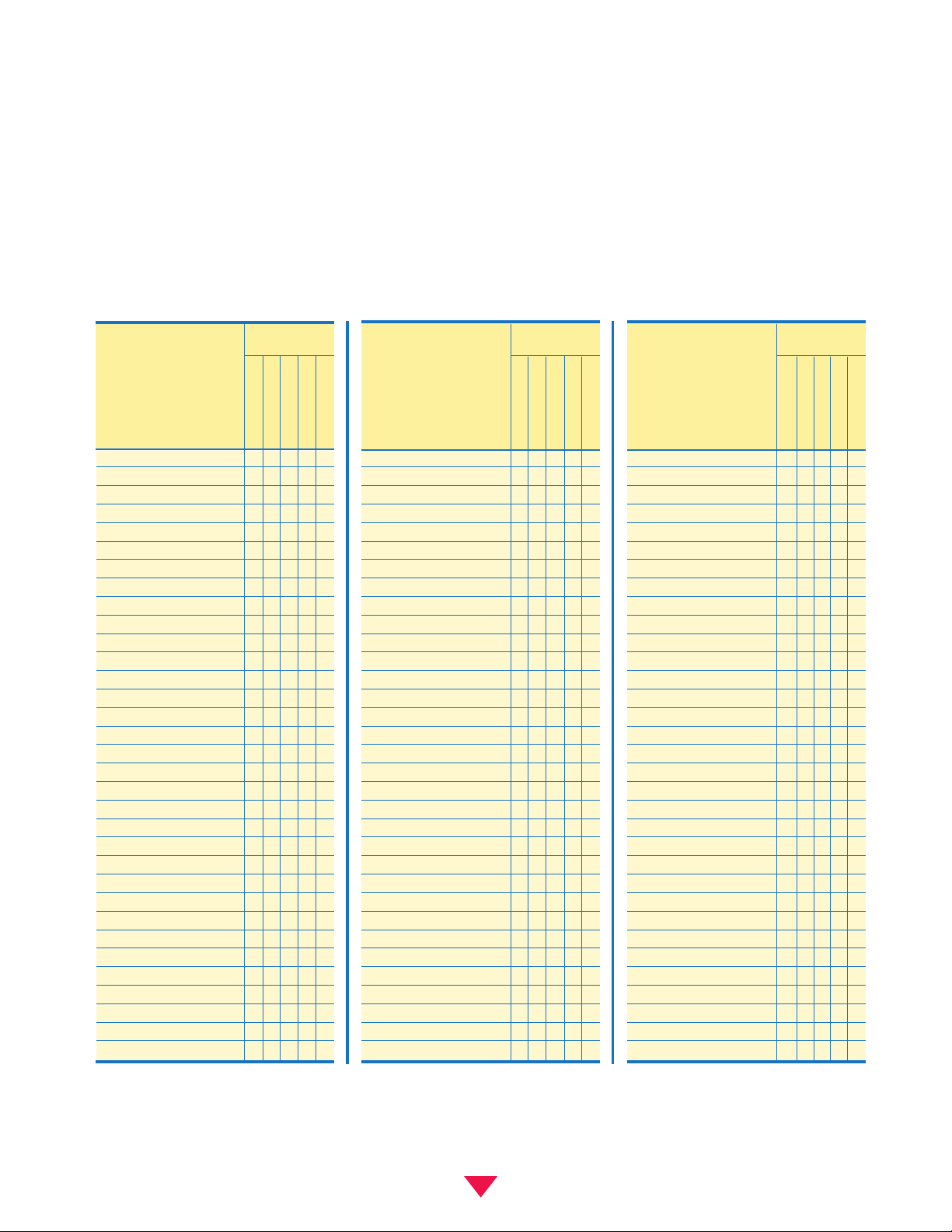
❶ Over 1000 psi – entire system must be 316 stainless steel.
Applicable only to hydrogen.
❷ Monel and 316 stainless steel are acceptable for oxygen service, provided the
instrument has been cleaned for oxygen service and is free from oil.
Oxalic Acid •
Oxygen (Gas)❷ • •
Palmitic Acid >99% •
Phosphoric Acid <80% •
Picric Acid <10% •
Propane (Dry) • • •
Sea Water (Flowing) •
Silver Nitrate <70% •
Sodium Bicarbonate <20% • •
Sodium Bisulfate <30% •
Sodium Carbonate <40% • •
Sodium Chromate <60% • • • •
Sodium Cyanide • •
Sodium Hydroxide < 40% •
Sodium Hypochlorite <25% •
Sodium Phosphate, Tri <60% • • •
Sodium Silicate <50% • • •
Sodium Sulfide <50% •
Stannous Chloride <10% •
Steam (Use siphon) • • • •
Stearic Acid •
Sulfur Dioxide (Dry) >99% •
Sulfur Trioxide (Dry) >99% •
Sulfuric Acid •
Tannic Acid <80% • • •
Tartaric Acid <50% • •
Tin Chloride (ous) <10% •
Toluene >99% • • • •
Turpentine >98% • • • •
Water (Tap) • • •
Whiskey •
Zinc Chloride <25% •
Zinc Sulphate <40% •
Crude Oil (Sour) •
Crude Oil (Sweet) • •
Ethyl Acetate •
Ethylene Oxide >99% • • •
Ferric Chloride <40% •
Ferric Sulfate <10% •
Ferrous Chloride <30% •
Ferrous Sulfate <50% •
Fluorine Gas (Dry) •
Formaldehyde <95% •
Formic Acid •
Freons • •
Furfural <10% •
Gasoline •
Glycerin >99% • • • •
Hydrobromic Acid •
Hydrochloric Acid •
Hydrofluoric Acid •
Hydrofluosilic Acid •
Hydrogen ❶ • •
Hydrogen Peroxide <50% •
Kerosene • • • •
Lactic Acid <70% •
Magnesium Chloride <40% •
Mercuric Chloride <60% •
Mercury >99% •
Milk •
Naphtha >99% • • • •
Naphthalene >99% • •
Nickel Chloride >99% •
Nitric Acid <95% •
Nitrogen • • • •
Oleic Acid •
Acetone • • •
Acetic Acid <40% •
Acetic Anhydride •
Acetylene (Dry) • •
Acrolein 100% •
Air • • • •
Alcohol, Ethyl • • •
Alum. Chloride >10% •
Alum. Sulfate 10-50% •
Ammonia Gas (Dry) • •
Ammonium Chloride <40% •
Ammonium Nitrate <50% •
Ammonium Sulfate <60% •
Aniline>99% •
Argon • • • •
Beer •
Benzidine >99% •
Benzene <50% • •
Benzoic Acid <70% •
Boric Acid <25% •
Bromine (Dry) •
Butane • • • •
Butyric Acid <10% •
Calcium Chloride <80% •
Calcium Hydroxide <50% •
Carbon Dioxide • • • •
Carbon Monoxide >99% • • • •
Chlorine (Dry) •
Chlorine (Moist) •
Chloroform (Dry) • •
Chromic Acid •
Citric Acid 10-50% •
Corn Oil •
Media Application Table
Ashcroft®Duragauge®Pressure Gauge
The media being measured must be
compatible with the wetted parts of the
pressure instrument. To use the chart
below, locate the media whose pressure
is to be measured and select a suitable
material from those available. Diaphr agm
seal information is contained in Bulletin
DS-1. This is a simplified chart and
assumes the media temperature is
below 200°F.
PLUS!
option, throttling
devices and/or a liquid-filled instrument
are recommended in applications with
pulsation or vibration. These recommendations are only a guide, as service life is
dependent on temperature, concentrations, catalysts that may be added, or
other conditions beyond our control.
Consult Stratford, CT customer service
for specific applications and for an y
media not listed. More complete corrosion guide available on our website at
www.dresserinstrument.com
in the
Application Data Section.
Media
Application
Media
Application
Media
Application
*
Any standard Bourdon tube material may be used in conjunction with a diaphragm
seal, but the gauge selection should take into consideration the corrosive environment
in which it is to operate. For diaphragm seals see Bulletin DS-1.
Brass or bronze
Steel
Stainless steel
Monel
Diaphragm seals*
Brass or bronze
Steel
Stainless steel
Monel
Diaphragm seals*
Brass or bronze
Steel
Stainless steel
Monel
Diaphragm seals*
Pressure Instrument
Material
Pressure Instrument
Material
Pressure Instrument
Material
9
Page 10
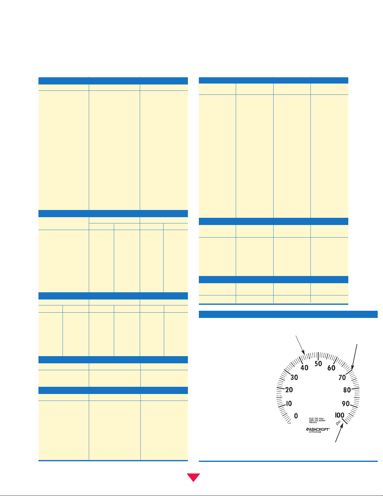
Pressure – kg/cm2and bar
Range
Figure Minor Outer scale
interval graduation in psi
0/1 0.1 0.01 0/14
0/1.6 0.2 0.02 0/22
0/2.5 0.5 0.02 0/35
0/4 0.5 0.05 0/55
0/6 0.5 0.05 0/85
0/10 1 0.1 0/140
0/16 2 0.2 0/220
0/25 5 0.2 0/350
0/40 5 0.5 0/550
0/60 5 0.5 0/850
0/100 10 1 0/1400
0/160 20 2 0/2200
0/250 50 2 0/3500
0/400 50 5 0/5500
0/600 50 5 0/8500
0/1000 100 10 0/14,000
0/1600 200 20 0/22,000
0/2500 500 20 0/35,000
0/4000 500 50 0/55,000
0/6000 1000 50 0/85,000
Vacuum
Range Figure interval Minor graduation
30/0 in. Hg 5 in 0.2 in
34/0 ft H2O 5 ft 0.5 ft
Range Tables
Ashcroft®Duragauge®Pressure Gauge
Pressure – psi
Range Figure interval Minor graduation
0/15 1 0.1
0/30 5 0.2
0/60 5 0.5
0/100 10 1
0/160 20 2
0/200 20 2
0/300 50 2
0/400 50 5
0/600 50 5
0/800 100 10
0/1000 100 10
0/1500 200 20
0/2000 200 20
0/3000 500 20
0/5000 500 50
0/6000 500 50
0/10,000 1000 100
0/20,000 2000 200
0/30,000 5000 200
0/50,000 5000 500
0/80,000 10,000 1000
0/100,000 10,000 1000
Compound
Figure interval Minor graduation
Range
in Hg psi in Hg psi
30˝ Hg/15 psi 5 3 0.5 0.2
30˝ Hg/30 psi 10 5 1 0.5
30˝ Hg/60 psi 10 10 1 1
30˝ Hg/100 psi 10 10 2 1
30˝ Hg/150 psi 10 20 5 2
30˝ Hg/200 psi 30 20 5 2
30˝ Hg/300 psi 30 50 5 2
30˝ Hg/400 psi 30 50 5 5
30˝ Hg/500 psi 30 50 5 5
30˝ Hg/600 psi 30 50 10 5
Combination
Range Figure interval Minor graduation
inner–psi outer–ft H
2
O psi ft H2O psi ft H2O
0/15 0/34 3 5 0.5 0.5
0/30 0/70 5 10 0.5 1
0/60 0/140 5 20 0.5 5
0/100 0/230 10 20 1 2
0/160 0/370 20 50 2 5
0/200 0/460 20 50 5 5
0/300 0/690 25 100 5 10
Compound – kg/cm2and bar
Range
Figure Minor Outer scale
interval graduation in psi
–1/0/1.5 0.2 0.02 30˝ Hg/20
–1/0/3 0.5 0.05 30˝ Hg/40
–1/0/5 0.5 0.05 30˝ Hg/70
–1/0/9 1 0.01 30˝ Hg/125
–1/0/15 2 0.02 30˝ Hg/215
–1/0/24 5 0.02 30˝ Hg/340
Vacuum – kg/cm2and bar
Range
Figure Minor Outer scale
interval graduation
–1/0 0.1 0.01 30˝ Hg
Retard
Range Figure interval Minor graduation
0/15 psi retard to 30 psi 1 psi-30 psi 0.25 psi-5 psi
0/30 psi retard to 60 psi 2 psi-60 psi 0.2 psi-10 psi
0/60 psi retard to 100 psi 2 psi-100 psi 0.5 psi-10 psi
30˝ Hg vac/75 psi 5˝ Hg/15 psi-150 psi 1˝ Hg/1 psi-5psi
retard to 150 psi
10˝ Hg vac/5 psi 2˝ Hg/1 psi 0.2˝ Hg/0.1 psi
retard to 30˝ Hg vac 30˝ Hg 5˝ Hg
retard to 30 psi 30 psi 5 psi
Metric Ranges
Standard Ranges
10
All Ashcroft dials have various
total graduation marks, figure intervals and minor graduations. Standard dual scale metric ranges have
a dominant metric inner scale. The
outer scale is specified in psi.
Some examples are shown. Duragauge gauges are made in accordance with ASME B40.1 entitled,
“Gauges, Pressure, Indicating Dial
T ype – Elastic Element ,” Accuracy
grade 2A (±0.5% of span). The
accuracy of a retard range gauge
applies only to the expanded portion of the scale. The error in the
compressed portion is –10% to
+20% of the span. Maximum
pressure at which a gauge is continually operated should not exceed
75% of full scale range. Consult
customer service in Stratford, CT
for non-standard dials.
Minor Graduations
Figure Intervals
Total Graduation
Graduations and figure intervals
Page 11
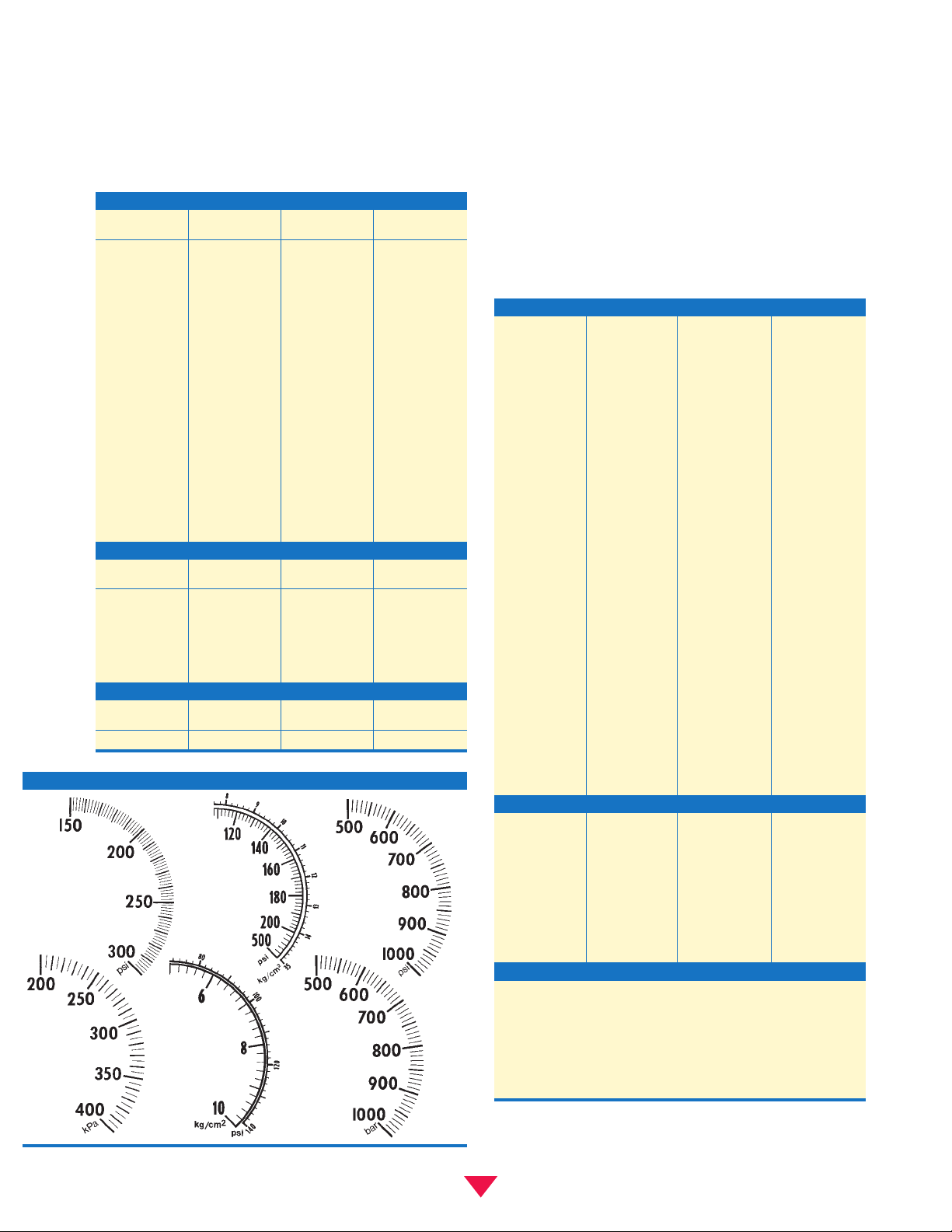
Range Tables
Ashcroft®Duragauge®Pressure Gauge
Receiver Gauge Ranges
Pressure – (kPa) kilopascal
Range Figure Minor Outer scale
interval graduation in psi
0/100 10 1 0/14
0/160 20 2 0/22
0/250 50 2 0/35
0/400 50 5 0/55
0/600 50 5 0/85
0/1000 100 10 0/140
0/1600 200 20 0/220
0/2500 500 20 0/350
0/4000 500 50 0/550
0/6000 500 50 0/850
0/10,000 1000 100 0/1400
0/16,000 2000 200 0/2200
0/25,000 5000 200 0/3500
0/40,000 5000 500 0/5500
0/60,000 5000 500 0/8500
0/100,000 10,000 1000 0/14,000
0/160,000 20,000 2000 0/22,000
0/250,000 50,000 2000 0/35,000*
0/400,000 50,000 5000 0/55,000*
Compound – (kPa) kilopascal
Range Figure Minor Outer scale
interval graduation in psi
–100/0/150 50 5 30˝ Hg/20
–100/0/300 50 5 30˝ Hg/40
–100/0/500 50 10 30˝ Hg/70
–100/0/900 100 10 30˝ Hg/125
–100/0/1500 200 20 30˝ Hg/215
–100/0/2400 500 20 30˝ Hg/340
Vacuum – (kPa) kilopascal
Range Figure Minor Outer scale
interval graduation
–100/0 10 1 30˝ Hg
Metric Ranges
Square Root Ranges
0/5 0/70 0/300 0/1500
0/10 0/80 0/350 0/2000
0/15 0/90 0/400 0/3000
0/20 0/100 0/500 0/4000
0/25 0/125 0/600 0/5000
0/30 0/150 0/700 0/10,000
0/40 0/175 0/800
0/50 0/200 0/900
0/60 0/250 0/1000
Receiver gauge
These ranges apply to any unit of pressure, temperature , liquid
level, flow, or other value specified. Units in psi pressure will be
denoted on the dial unless specified. Av ailable with input r anges
of 3-15 psi or 3-27 psi.
11
0/1
0/2
0/3
0/4
0/5
0/6
0/7
0/8
0/9
0/10
0/11
0/12
0/14
0/15
0/16
0/17
0/18
0/19
0/20
0/21
0/25
0/26
0/28
0/30
0/35
0/40
0/45
0/50
0/55
0/60
0/65
0/70
*
200° Arc
0/75
0/80
0/85
0/90
0/95
0/100
0/120
0/140
0/160
0/180
0/200
0/250
0/300
0/350
0/400
0/500
0/600
0/700
0/760
0/800
0/900
0/1000
0/1500
0/2000
0/3000
0/4000
0/5000
0/10,000
0/15,000
0/20,000
0/30,000
0/50,000
30/80
5/110
20/120
40/120
20/150
30/150
40/150
50/150
30/180
130/180
100/200
20/220
40/220
30/240
100/240
30/250
50/250
100/250
30/300
50/300
80/300
100/300
50/350
80/350
150/350
100/400
150/400
50/500
100/500
200/500
300/500
200/700
100/600
200/700
100/800
200/800
300/800
400/800
450/800
500/800
650/800
200/900
400/900
700/900
200/1000
400/1000
500/1000
600/1000
800/1000
200/1100
400/1200
500/1200
600/1200
1000/1500
300/1600
1000/1600
600/1800
900/1800
1200/1800
700/2000
1000/2500
1500/2500
900/3000
1500/3000
Compound Ranges
30˝ Hg/0/15 psi
30" Hg/0/30 psi
30" Hg/0/60 psi
30" Hg/0/100 psi
30" Hg/0/150 psi
30" Hg/0/500 psi
30" Hg/0/800 psi
Page 12
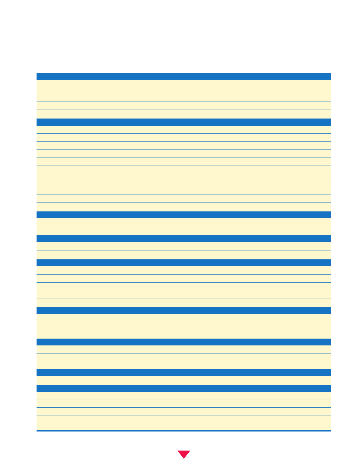
Options
Ashcroft®Duragauge®Pressure Gauge
Case and ring options Code Comments
Hermetically Sealed Case H Available on types 41⁄
2˝ 1279 and 4
1
⁄
2,˝ 6˝ 1379 models only.
Gauge Heater HD Used for outdoor applications or other services where ambient temperatures
are –50°F. Available on 41⁄
2˝ 1379 model only.
Flush Mounting Ring - Steel, Black Epoxy 56 Available on 41⁄
2˝ 1279 and 4
1
⁄
2,˝ 6˝ 1379 models only (also called 1278 flush mounting ring).
Flush Mounting Ring - Stainless Steel, Polished 57 Available on 41⁄
2˝ 1279 and 4
1
⁄
2,˝ 6˝ 1379 models only (also called 1278 flush mounting ring).
Bourdon tube and system assembly options
AND10050-4 (1⁄
4˝ Tubing Conn.) AM
1
⁄
4˝ High Pressure Tubing Conn. 09 Standard on ranges 30,000 psi and up.
Overload Stop OS Used to protect the gauge against extreme pressures.
Underload Stop VS Used to protect low pressure gauges against vacuum.
Throttle Screws – Brass, stainless steel and Monel TS 0.031˝ Standard. Other sizes: .006, .0135, .020, .040, .050 and .070 (Monel .040 only).
Capillary Bleeder BG Available in model 1379, 41⁄
2˝ Lower conn. only with stainless steel system. Max. pressure 1000 psi.
Tip Bleeder TB Available in bronze, St. St. or Monel Bourdon tube gauges only. Max. pressure 15,000 psi.
Cleaning for Gaseous Oxygen 6B Not available with steel or bronze and
PLUS!
option Bourdon tubes. If Gauge is liquid-filled specify
Halocarbon as the fill.
Cleaning for Liquid Oxygen Service 6D
Free from Mercury Contamination MF Provided with free from mercury contamination certification (CD-2).
Link options
Slotted Link for Sudden Pressure Increase RJ
Unless specified, slotted link set for pressure increase. Accuracy 1% F.S. with slotted link.
Slotted Link for Sudden Pressure Decrease S4
Liquid-filling options
Silicone Fill GV
Halocarbon Fill GX For oxidixing media. Examples: chlorine, oxygen, nitric acid and sulfuric acid.
Pointer options
Red Set Hand (Single) SH Single stationary set hand used to indicate a specific pressure.
Red Set Hand (Double) SJ Double stationary set hand used to indicate 2 specific pressures.
Red Set Hand (Adjustable) EO Internally adjustable.
Maximum Pointer EP Externally reset by a knob on outside of an acrylic window.
Minimum Pointer EQ Externally reset by a knob on outside of an acrylic window.
Window options
Acrylic Window PD Ambient temperature limits –50/180°F.
Laminated Safety Glass SG Ambient temperature limits –50/200°F.
Non Glare Glass NG Ambient temperature limits –50/350°F.
Marking and tagging options
Dial Marking DA Service marking printed on dial.
Paper Tagging of Carton and Gauge NN Tag is bonded to gauge case and carton.
Stainless Steel Tagging of Gauge Case NH 300 series stainless steel tag is wired to gauge case.
Calibration options
Calibrate to Absolute Pressure AB
Test and certificate options
Mass Spectrometer Leak Test ML
Special Certificate of Conformance CD-1A Non standard certificate of conformance.
Certificate of Conformance CD-1 Conformance to specifications and/or drawings.
Free From Mercury Contamination CD-2 Conformance to specifications and/or drawings and free from mercury contamination.
Individual Certified Calibration Chart CD-4
12
Page 13
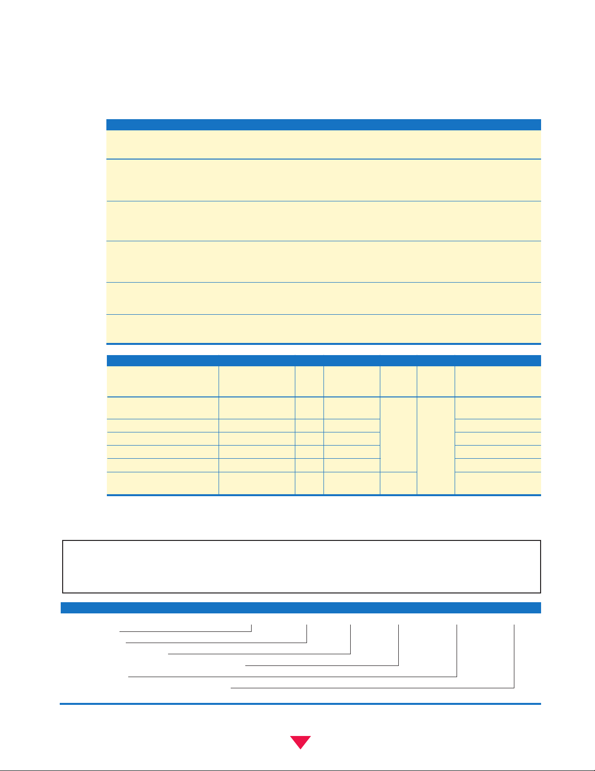
To order a Duragauge (sample coding shown)
Select: 45 1279 RS* 04L XXX 0/2,000 psi
1. Dial size–41⁄
2˝
2. Case type–1279
3. Bourdon tube and socket code
4. Connection–1⁄
4 NPT (02),
1
⁄
2 NPT (04), Lower (L), Back (B)
5. Optional features
6. Pressure range (see range tables on pages 10 & 11)
Table A – Case selection & mounting
Ring: Style
Dial Size Ordering Case Case: Material Material Mounting/Connection
(in) Code Type Finish Finish
41⁄
2 (45) 1279
(1 )
Phenolic Threaded Stem– Lower or back
(Black) Reinforced Surface– Lower or back
Polypropylene Flush– Back: Specify X56
(Black)
41⁄
2, 6, 8
1
⁄
2 (45)(60)(85) 1377 Aluminum Hinged Flush– Back
Black epoxy coating Steel Stem– Lower or back
Black wrinkle
enamel coat
41⁄
2, 6, 8
1
⁄
2 (45)(60)(85) 1379
(1 )
Aluminum 41⁄
2˝, 6˝ Threaded rein- Stem– Lower or back
Black epoxy coating forced polypropylene Surface– Lower or back
81⁄
2˝ Hinged steel, black Flush– Back, specify X56
wrinkle enamel coat 81⁄
2˝ standard
6 (45) 2462 Polypropylene Bayonet lock Stem– Lower or back
(fiberglass reinforced) Polypropylene Surface– Lower or back, specify XBF
(Black) (Black) Flush– Back, specify XBQ
6 (60) 1379
(1 )
Aluminum 6˝ Threaded rein- Flush– Lower or back
(high pressure) Black epoxy coating forced polypropylene Surface– Lower or back
How to Order
Ashcroft®Duragauge®Pressure Gauge
NOTES:
(1) Liquid-fillable or hermetically sealed when kit 101A202-01 (lower) or kit 101A203-01 (back) is ordered.
(2) For selection of the correct Bourdon system material, see the media application table on page 9.
(3) Use on applications where NACE MR-01-75 is specified for selection of the correct Bourdon system material.
(*) “S” denotes solid front case design
Table B – System, connection & location
Bourdon Tube & Tip Material
(2)
Tube & NPT Conn.
(all joints TIG welded except code“A”) Socket Socket Conn. & Location & Range Selection
Material
(2)
Code Case Style Code Code Code Limits (psi)
C510 Grade A Phosphor Bronze Tube
Brass (A) (S) Solid Front Vac./1000
Brass Tip, Silver Brazed (04) 1⁄
2
4130 alloy steel 1018 steel (B) (S) Solid Front (STD) Lower (L) Vac./5000
316 stainless steel 1018 steel (R) (S) Solid Front (02) 1⁄
4 Vac./20,000
316 stainless steel 316 stainless steel (S) (S) Solid Front (OPT) Back (B) Vac./20,000
K 500 Monel
®(3)
Monel 400 (P) (S) Solid Front Vac./30,000
Inconel 718
®
316 stainless steel (WW) (SH) Solid Front (09) 1⁄
4 50,000/80,000/100,000
Herm. Sealed High Pres.
13
GAUGE ACCURACY
Duragauge gauges are made in accordance with ANSI B40.1 (Gauges, pressure and vacuum, indicating dial type – elastic element), Accuracy
Grade 2A (±0.5% of span). Because of hysteresis, the downscale accuracy of a 20,000 psi gauge (S) or (R) code is 1.2%.
Maximum pressure at which a gauge is continually operated should not exceed 75% of full scale range.
Page 14
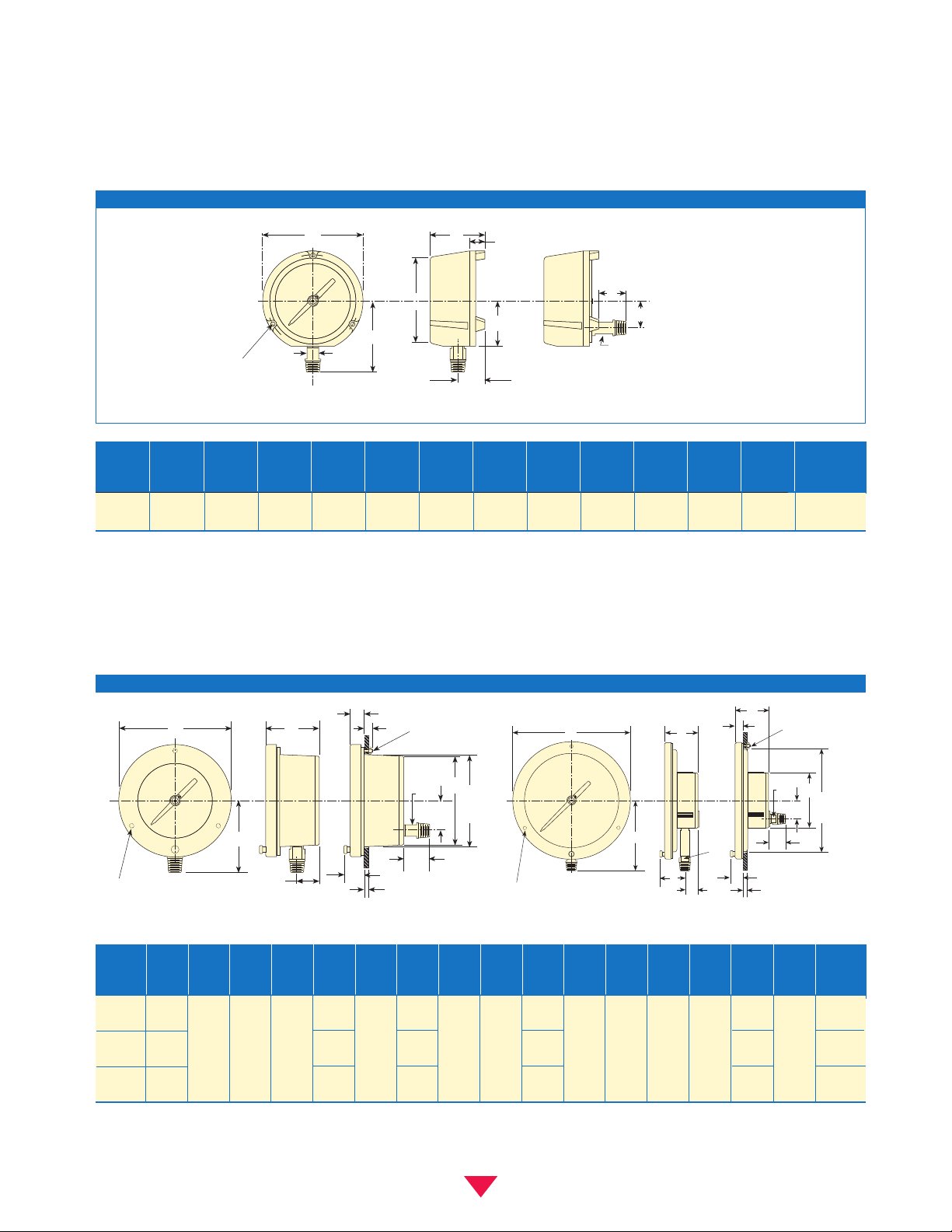
Dial
Size A B C D E F G H K M P S T U CC LL Weight
Inches (lbs)
Dial
Size A B C D E F G H J L T V Weight
Inches (lbs)
Dimensions
Ashcroft®Duragauge®Pressure Gauge
14
Case Type 1377
Case Type 1279
4
1
⁄
2˝ Lower Connection
41⁄
2˝ Back Connection
41⁄
2˝ & 6˝ Lower Connection 4
1
⁄
2˝ & 6˝ Back Connection
81⁄
2˝ Back Connection
81⁄
2˝ Lower Connection
41⁄
2
513⁄16 33⁄8 51⁄16 15⁄8 53⁄8 15⁄8 315⁄16
3
⁄4 1 .218
5
⁄8 25⁄8
21⁄
2
(148) (86) (129) (41) (137) (41) (100) (20) (25) (6) (16) (67)
41⁄
2
63⁄
32 5
3
⁄8 315⁄16 47⁄8
#10-24 21⁄
2
(148) (137) (100) (124)
6
79⁄16 27⁄8 43⁄4 11⁄16 7 15⁄8 41⁄2 13⁄8 11⁄16 61⁄2 21⁄85⁄8
5
⁄8
3
⁄4
1
⁄
4–20
1
⁄8–1⁄2
3
(192) (73) (121) (27) (178) (41) (114) (35) (27) (165) (54) (16) (16)
(19) (3)(13)
81⁄
2
101⁄16 95⁄8 6 9 1
⁄
4–20 4
1
⁄
2
(257) (244) (152) (229)
A
B
J
H
F
T
3-L dia. holes
on E dia. B.C.
G
T
C
V
D
A
B
S
U
Nuts & washers
not supplied by
Dresser
A
B
B
S
Nuts & washers
not supplied by
Dresser
G
3 Mounting studs CC threaded
equally spaced on E dia. B.C.
D
K
LL
C
M
T
Hole in
panel
F
G
H
3 Mounting studs CC threaded
equally spaced on E dia. B.C.
T
P
D
K
C
T
F
H
LL
M
Hole in
panel
Page 15
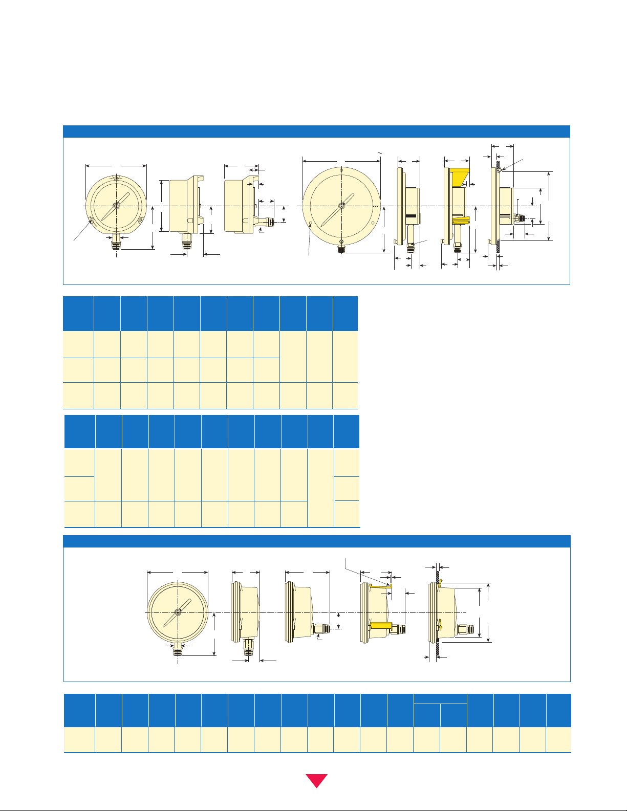
Dial
Size A B C D E F G H J K
Inches
41⁄2
513⁄16 313⁄32 47⁄8 15⁄8 53⁄8 11⁄8 315⁄16
(148) (86) (124) (41) (137) (42) (100)
7
⁄8 11⁄16
6
79⁄16 31⁄2 65⁄8 15⁄8 7 11⁄2 41⁄2
(20) (27)
—
(192) (89) (162) (41) (178) (42) (114)
81⁄2
101⁄16 27⁄8 43⁄4 11⁄16 95⁄8 15⁄8 6 13⁄8
—
1
1
⁄16
(256) (73) (121) (27) (244) (41) (152) (35) (27)
Dial
LL
Size A B C D E F G H H-1 J KK L
Min. Max.
M S T Wgt.
Inches (lbs)
6
63⁄8 27⁄16 43⁄47⁄8 53⁄8 15⁄8 315⁄16 49⁄16 49⁄325⁄64 211⁄16 .2181⁄16
1
⁄2 6
11
⁄165⁄8
6
(163) (62) (120) (22) (137) (42) (100) (116) (109) (2) (69) (6) (2) (13) (152) (17) (16)
Dimensions
Ashcroft®Duragauge®Pressure Gauge
15
Case Type 1379
Case Type 2462
6˝ Lower Connection
6˝ Back Connection
Stem Surface Panel
41⁄
2˝ & 6˝ Lower Connection 4
1
⁄
2˝ & 6˝ Back Connection
81⁄
2˝ Back Conn.
81⁄
2˝ Wall Conn.
81⁄
2˝ Lower Conn.
Note: Dimensions in brackets ( ) are millimeters.
Dial
Size L M N P S T V CC LL Wgt.
Inches (lbs)
41⁄2 21⁄2
.218
— —
21⁄8
—
5
⁄8 25⁄8
—
6
(6) (54) (16) (67)
1
⁄
8-
1
⁄
2
31⁄8
(3)(13)
81⁄2
9 39⁄
32
—
11
⁄16
— —
#10-24 41⁄2
(228) (83) (17)
D
A
G
T
B
G
N
S
D
M
Hole in
panel
Nuts & washers
not supplied by
Dresser
C
S
B
T
F
H
LL
K
3 Mounting studs CC threaded
equally spaced on E dia. B.C.
P
P
A
C
G
3-L dia. holes
on E dia. B.C.
T
D
B
J
W
H
V
F
T
A
T
G
B
C
D
H
F
T
3-L Dia holes on E Dia. B.C.
KK
H-I
J
LL
M
Hole in
C
panel
S
Page 16

All specifications are subject to change without notice.
All sales subject to standard terms and conditions.
© Instrument Division, Dresser Equipment Group, Inc.
50MWP 3/00 1P8/94
Instrument Division Sales and
Customer Service Locations
Japan
Dresser Japan Inc.
Room 318, Shin Tokyo Building
3-1 Marunouchi 3-Chome,
Chiyoda-ku, Tokyo, Japan
Tel: 813-3201-1501/1506
Fax: 813-3213-6567/6673
Korea
Dresser International S.A.
Korea Office
#2015 Kuk Dong Bldg.
60-1, 3-KA, Choongmu-Ro,
Chungku, Seoul, Korea 100-705
Tel: 82-2-2274-079-2/3
Fax: 82-2-2274-0794
Mexico
Dresser Instruments S.A. de, C.V.
Henry Ford No. 114,
Esq. Foulton, Fracc
Industrial San Nicolas
54030 Tlalneplantla edo
de Mexico 54030
Tel: 525-310-7217
Fax: 525-310-2608
Saudi Arabia
Dresser Al Rushaid
(DARVICO)
P.O. Box 10145
Jubail Industrial City
Saudi Arabia 31961
Tel: 966-3-341-0278
Fax: 966-3-341-7624
Singapore
Dresser Singapore Pte Ltd.
Instrument Operations
Block 1004 Toa Payoh North
#07-15/17
Singapore 318995
Tel: 65-252-6602
Fax: 65-252-6603
United Kingdom
Dresser Europe GmbH
East Gillibrands,
Skelmersdale,
Lancashire WN8 9TU
United Kingdom
Tel: 44-16-95-52600
Fax: 44-16-95-52693
Venezuela
Manufacturas Petroleras
Venezolanas S.A.
KM 7 Carretera A
El Mojan Calle 18,
#15B355 ZONA
Maracaibo Edo Zulia, Venezuela
Tel: 58-61-579-762 or 070
Fax: 58-61-579-461
U.S. Headquarters
Stratford, Connecticut
250 E. Main Street
Stratford, CT 06614-5145
Tel: (203) 378-8281
Fax: (203) 385-0499
U.S. Sales Offices
Chicago, Illinois
400 W. Lake Street
Suite 318
Roselle, IL 60172-3573
Tel: (630) 980-9030
Fax: (630) 980-9440
Hartford, Connecticut
1501 East Main Street
Meriden, CT 06450-2860
Tel: (203) 235-0450
Fax: (203) 235-0593
Houston, Texas
3838 North Sam Houston
Parkway East
Suite 120
Houston, TX 77032
Tel: (281) 590-1092
Fax: (281) 590-7100
Los Angeles, California
3931 MacArthur Blvd.
Suite 202
Newport Beach, CA 92660
Tel: (949) 852-8948
Fax: (949) 852-8971
Mobile, Alabama
851 South Beltline Highway
Suite 402, 4th Floor
Mobile, AL 36606
Tel: (334) 473-1692
Fax: (334) 473-1782
International Headquarters
Stratford, Connecticut
250 E. Main Street
Stratford, CT 06614-5145
Tel: (203) 378-8281
Fax: (203) 385-0357
International Operations
Brazil
Dresser Industria e
Comercio Ltda.
Divisao Manometros Willy
Rua Senador
Vergueiro No. 433
09521-320 Sao Caetano do Sul
Sao Paulo, Brazil
Tel: 55-11-453-5477
Fax: 55-11-453-8710
Canada
Dresser Canada, Inc.
2135 Meadowpine Blvd.
Mississauga,
Ontario L5N 6L5
Canada
Tel: 905-826-8411
Fax: 905-826-9106
China
Dresser Trading
Room 2403, 24th Floor
CITIC Bldg.
19 Jianguo Menwai St.
Beijing, P.R.C.
Tel: 86-10-6500-3139
Fax: 86-10-6512-0300
France
Dresser Europe GmbH
Division Instrumentation
74, Rue d’ Arceuil
F-94578, Silic 265,
France
Tel: 33-01-49-79-22-59
Fax: 33-01-46-86-25-24
Germany
Dresser Europe GmbH
Postfach 11 20
Max-Planck-Str. 1
D-52499 Baesweiler
Germany
Tel: 49-2401-8080
Fax: 49-2401-7027
Visit our web site
www.dresserinstruments.com
a Halliburton company
 Loading...