


PikoSys Vertriebs GmbH
Wildbichler Straße 2e
A – 6341 Ebbs
Tel. +43 5373 43499-100
Fax: +43 5373 43499-999
info@pikosys.com
www.pikosys.com
Handbuch / Operation
Manual PikoLoad

Versionhistorie / Revision History
Handbuch / Operation Manual PikoLoad Seite / Page 2 / 35
Version 4
Versionhistorie / Revision History
Version Datum / Date Änderungen / Changes Name
1 31.08.2009 Erste Version / First version KeAr
2 30.10.2009 Korrekturen HOST
3 02.11.2009 Korrekturen HOST
4 02.03.2010 Korrekturen / Corrections HOST

Inhaltsverzeichnis
Handbuch / Operation Manual PikoLoad Seite / Page 3 / 35
Version 4
Inhaltsverzeichnis
Versionhistorie / Revision History............................................................................ 2
Inhaltsverzeichnis.................................................................................................... 3
Abbildungsverzeichnis.............................................................................................. 4
A DEUTSCH ............................................................................................................. 5
1 Einführung .......................................................................................................... 5
1.1 Allgemeines .................................................................................................. 5
1.2 Funktionsbeschreibung Standard PikoLoad ........................................................ 5
2 Inbetriebnahme .................................................................................................. 8
2.1 Verpackungsinhalt PikoLoad-Paket ................................................................... 8
2.2 Montage und Anschluss des PikoLoad Geräts ..................................................... 9
2.2.1 FMS-Kabel erstellen (kein FMS-Stecker im Fahrzeug vorhanden) .............. 9
2.2.2 Installation im Fahrzeug ...................................................................... 9
2.2.3 Tacho anschließen (nur bei Tachotausch) .............................................10
3 Funktion und Bedienung PikoLoad .................................................................... 11
3.1 Einlegen der Unternehmerkarte ......................................................................11
3.2 Tacho auf Unternehmen sperren .....................................................................12
3.3 LED-Anzeigen PikoLoad..................................................................................13
3.4 Datenauswertung..........................................................................................14
3.4.1 Daten auf USB-Stick auslesen.............................................................14
3.4.2 Beschreibung Dateien USB-Stick .........................................................14
4 Anhang.............................................................................................................. 15
4.1 Technische Daten..........................................................................................15
4.2 Steckerbelegungen........................................................................................16
4.2.1 CAN 1 Steckerbelegung PikoLoad ........................................................16
4.2.2 CAN 2 Steckerbelegung PikoLoad ........................................................17
4.2.3 RS 232 Steckerbelegung am PikoLoad .................................................18

Abbildungsverzeichnis
Handbuch / Operation Manual PikoLoad Seite / Page 4 / 35
Version 4
Abbildungsverzeichnis
Abbildung 1: FMS-Kabel erstellen 9
Abbildung 2: Kabelanschluss PikoLoad 9
Abbildung 3: Anschluss an Tachograph 10
Abbildung 4: Pinbelegung C-CAN Tacho 10
Abbildung 5: Auf Scharnier drücken 11
Abbildung 6: Frontklappe öffnen 11
Abbildung 7: Unternehmenskarte einlegen (Chip nach oben) 12
Abbildung 8: Eingelegte Unternehmenskarte 12
Abbildung 9: LED-Anzeigen 13
Abbildung 10: Orderstruktur USB-Stick 14
Abbildung 11: Beispieldaten 14
Abbildung 12: Beispieldaten 14
Abbildung 13: PikoLoad CAN 1 Steckerbelegung 16
Abbildung 14: PikoLoad CAN 2 Steckerbelegung 17
Abbildung 15: Anschluss PikoLoad CAN 2 17
Abbildung 16: PikoLoad RS232 Steckerbelegung 18
Abbildung 17: Anschluss PikoLoad RS 232 18

Einführung
Handbuch / Operation Manual PikoLoad Seite / Page 5 / 35
Version 4
A DEUTSCH
1 Einführung
1.1 Allgemeines
Das Standard PikoLoad ist ein einfaches, leicht zu installierendes Gerät zum
automatischen Download des Massenspeichers eines digitalen, remote-download fähigen
Tachographen. Mit PikoLoad sind Sie in der Lage ihre regelmäßig gesetzlich
vorgeschriebenen Downloads des Massenspeichers automatisch durchzuführen. Es entfällt
das aufwändige Organisieren der Mitarbeiter und unnötig lange Downloadzeiten. Keine
Schulung, keine Einstellung und keine Bedienung notwendig.
Einfach Unternehmenskarte einlegen, Anstecken, fertig.
Die Daten werden bei Bedarf auf einen USB-Stick geladen und dort gespeichert. PikoLoad
hat einen internen Speicher zur Speicherung von ca. 2 Jahren Massenspeicher. Zusätzlich
bietet PikoLoad die Möglichkeit während der Fahrt, die im Tachograph eingelegten
Fahrerkarten auszulesen und ebenfalls zu speichern. Alle Daten sind in universeller Form
gespeichert und können mit handelsüblicher Auswertesoftware verarbeitet werden. Für
Nutzer von Bordcomputersystemen steht eine einfache Schnittstelle zur Übernahme der
Daten zur Verfügung. Kein aufwändiges Implementieren der Funktionen für den Download
der Daten nötig.
1.2 Funktionsbeschreibung Standard PikoLoad
Das Programm des Standard PikoLoad hat folgende Funktionsabläufe:
Authentifizierung der im PikoLoad eingelegten Unternehmenskarte beim digitalen
Tachographen für den Download des Massenspeichers
• Festlegen der Zeiträume (Tage), die heruntergeladen werden sollen
• Deklaration der Daten die heruntergeladen werden sollen:
o
Überblick
o
Aktivitäten
o
Technische Daten
o
Detaillierte Geschwindigkeit (24 Stunden)
o
Ereignisse/Fehler
o
sowie eingelegte Fahrerkarten
• Herunterladen der deklarierten Daten
• Bildung von .DDD Dateien für
o
die Massenspeicherdaten
o
die Fahrerkarten.
• Die Daten sind digital signiert und entsprechen den Daten, die an der frontseitigen
Tachographen-Schnittstelle geladen werden können.
• Ausgabe der Daten auf:
o
USB-Stick, falls gesteckt
o
Zweiter CAN-Schnittstelle am PikoLoad (Broadcast)
o
Serieller Schnittstelle am PikoLoad (auf Abruf)

Einführung
Handbuch / Operation Manual PikoLoad Seite / Page 6 / 35
Version 4
Das PikoLoad prüft die eingelegte Unternehmenskarte in Verbindung mit dem digitalen
Tachographen. Dabei wird auch geprüft, ob die Unternehmenskarte noch gültig ist und die
Daten für das Unternehmen gesperrt sind.
Es können nur Daten heruntergeladen werden, die der eingelegten Unternehmenskarte
zugeordnet werden. Daher ist es wichtig den Tachographen auf die eingelegte
Unternehmenskarte zu sperren, bevor die Unternehmenskarte in das PikoLoad eingelegt
wird.
Auf den USB Stick werden nur Daten gespeichert die der im PikoLoad eingelegten
Unternehmenskarte zugeordnet sind. Daher bitte die Unternehmenskarte im PikoLoad
eingelegt lassen bis alle Daten auf den USB-Stick gespeichert wurden.
Sollte das PikoLoad Daten zu verschiedenen Unternehmenskarten haben (MehrfahrzeugBetrieb) können diese (nacheinander) nach dem Einlegen in das PikoLoad auf den USBStick gespeichert werden.
Auf den USB-Stick werden alle Fahrerkartendaten gespeichert, die mit der eingelegten
Unternehmenskarte geladen wurden. Die Fahrerdaten werden mit der
Fahrerkartennummer nicht mit dem Fahrernamen gespeichert (Datenschutzgründe).
Auf der zweiten CAN Schnittstelle und der seriellen Schnittstelle werden nur Daten
ausgegeben falls eine Unternehmenskarte im PikoLoad eingelegt ist. Es werden nur die
Daten ausgegeben, die der eingelegten Unternehmenskarte zugeordnet sind.
Fahrerkartendaten werden nur ausgegeben sofern eine Fahrerkarte im Tachograph
eingelegt ist (es wird nur die aktuell eingelegte(n) Fahrerkarte(n) ausgegeben. Sobald die
Fahrerkarte aus dem Tacho entfernt wird, wird die laufende Ausgabe der Daten noch
beendet und anschließend keine weiteren Fahrerkartendaten mehr ausgegeben.
Selbiges gilt für die Ausgabe auf der seriellen Schnittstelle.
Bitte beachten Sie, dass auf der seriellen Schnittstelle die Daten aktiv abgerufen werden
müssen (siehe Beschreibung).
Auf der zweiten CAN Schnittstelle werden die Daten zyklisch ausgegeben (Broadcast).
Das PikoLoad lädt folgende Datenblöcke für die Aktivitäten:
• erster Datenblock (= .DDD-File) ist vom erstmaligen Gebrauch des PikoLoad in diesem
Fahrzeug bis maximal 3 Monate in die Vergangenheit (falls Daten vorhanden).
• Danach werden .DDD Dateien mit jeweils 14 Tagen (Aktivitäten von 14 Tagen) gebildet
und gespeichert.
• Das PikoLoad prüft im Betriebsmodus, ob alle Daten bis zum aktuellen Tag geladen
wurden. Fehlende Tage werden ggf. geladen und gespeichert.
Der letzte „unfertige“ 14 Tage-Block wird ebenfalls als .DDD Datei ausgegeben und enthält
die Aktivitäten der Tage bis zur letzten 14 Tage- .DDD Datei (ohne aktuellem Tag)
Dadurch entsteht ein lückenloses Auslesen und Speichern der Daten im PikoLoad.
Bitte beachten Sie, dass nur die Daten des letzten Tages (nicht aktueller Tag) als
abgeschlossen gelten. Die Daten des aktuellen Tages unterliegen noch Änderungen und
werden erst Mitternacht abgeschlossen und erst dann vom PikoLoad geladen.
Die maximale Aufzeichnungs- und Speicherzeit hängt von den jeweiligen
Massenspeicherdaten ab, jedoch werden mindestens 2 Jahre in die Vergangenheit im
PikoLoad (Ein-Fahrzeug Betrieb) gespeichert.
Sobald eine Fahrerkarte erfolgreich am Tachographen angemeldet wurde, wird diese
ebenfalls ausgelesen und gespeichert. Sollten beide Fahrerkartenslots am Tachograph
genutzt werden, werden auch beide Karten ausgelesen und gespeichert.
Bitte beachten Sie, dass das Lesen der Fahrerkartendaten am Tachographen pro Karte ca.
2 Minuten benötigt. Erst dann stehen diese Daten zum Auslesen für das PikoLoad bereit.
Hinweis: Der Download der Fahrerkarte wird zyklisch alle 10 Minuten gestartet.

Einführung
Handbuch / Operation Manual PikoLoad Seite / Page 7 / 35
Version 4
Auf RS 232 und der zweiten CAN-Schnittstelle wird jeweils die zuletzt geladene
Fahrer/Beifahrerkarte ausgegeben.
Auf dem USB-Stick wird die an die erste geladene Fahrer/Beifahrerkarte
ausgegeben.
Das Programm und die Funktionsweise des PikoLoad basieren auf der offiziell
veröffentlichten „User Documentation for Remote Download“ und funktionieren mit
remote-download-fähigen Tachographen der Hersteller Continental, Stoneridge und Actia.
Fahrzeuge mit FMS-Schnittstelle
Zusätzlich zum Herunterladen des Massenspeichers des digitalen Tachographen werden falls vorhanden – FMS-Daten durchgeschleift und stehen unverändert auf der zweiten CAN
Schnittstelle am PikoLoad zur Verfügung. Eine ggf. bereits vorhandene Anbindung an die
FMS-Daten wird dadurch nicht beeinträchtigt.
Auf der seriellen Schnittstelle stehen die FMS-Daten zum Abruf bereit. Es wird der jeweils
letzte empfangene Wert ausgegeben.
Bitte beachten Sie, dass keine FMS-Daten auf den USB-Stick ausgegeben werden.
Inbetriebnahme
Handbuch / Operation Manual PikoLoad Seite / Page 8 / 35
Version 4
2 Inbetriebnahme
2.1 Verpackungsinhalt PikoLoad-Paket
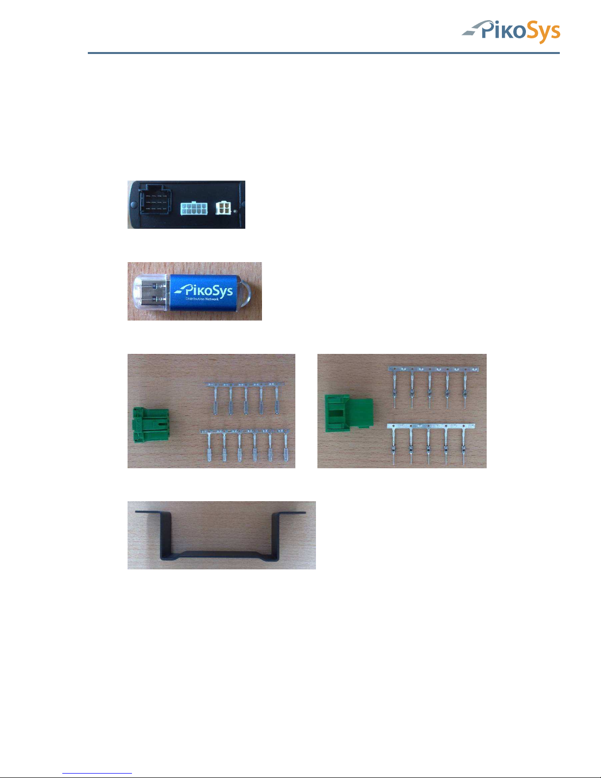
Das PikoLoad-Paket besteht aus folgenden Komponenten:
1 PikoLoad Gerät
1 Pikosys USB Stick
2 Stecker grün 12 polig
1 Haltebügel

Inbetriebnahme
Handbuch / Operation Manual PikoLoad Seite / Page 9 / 35
Version 4
2.2 Montage und Anschluss des PikoLoad Geräts
2.2.1 FMS-Kabel erstellen (kein FMS-Stecker im Fahrzeug vorhanden)
Erstellen Sie das FMS Kabel im Fahrzeug, falls kein FMS-Stecker vorhanden ist
1. Erstellen Sie die Kabel für das PikoLoad (genaue Beschreibung siehe Anhang).
Pin 1
Pin 6
Pin 9
Pin 10
Pin 12
FMS-Stecker
(female)
Abbildung 1: FMS-Kabel erstellen
2. Schließen Sie das Kabel wie folgt im Fahrzeug an:
Pin 1 Klemme 31 (Masse)
Pin 6 CAN high (C-CAN Tacho Pin 5 + ggf. FMS CAN high)
Pin 9 CAN low (C-CAN Tacho Pin 7 + ggf. FMS CAN low)
Pin 10 Klemme 15 (24 V DC UBat - Zündung)
Pin 12 Klemme 30 (24 V DC)
2.2.2 Installation im Fahrzeug
2.2.2.1 FMS-Stecker im Fahrzeug vorhanden oder erstellt
FMS-Stecker
(female)
Pin 1
Pin 6
Pin 9
Pin 10
Pin 12
PikoLoad
Abbildung 2: Kabelanschluss PikoLoad
Verbinden Sie den FMS-Stecker mit dem PikoLoad

Inbetriebnahme
Handbuch / Operation Manual PikoLoad Seite / Page 10 / 35
Version 4
2.2.3 Tacho anschließen (nur bei Tachotausch)
Bitte führen Sie diesen Schritt nur aus, falls ihr Tachograph nicht bereits
werkseitig remote-download fähig geliefert wurde (mit grünen AnschlussStecker)
Anschluss Tacho (Beispiel Continental)
Abbildung 3: Anschluss an Tachograph
1
5
4
8
Abbildung 4: Pinbelegung C-CAN Tacho
Pin 1 nicht verwendet
Pin 2 GND
Pin 3 nicht verwendet
Pin 4 nicht verwendet
Pin 5 CAN high
Pin 6 nicht verwendet
Pin 7 CAN low
Pin 8 nicht verwendet
Schließen Sie den C-CAN Stecker (rot) am C-CAN des Tachographen an.
Achtung: Die Stecker sind codiert (passt nur in C-CAN)!
Bitte benutzen Sie unter keinen Umständen einen anderen Anschluss am Tachographen!
Sie beinträchtigen sonst die korrekte Funktionsweise des Tachographen. Bitte beachten
Sie auch, dass diese Arbeiten am Tachographen ausschließlich von einer autorisierten
Werkstatt durchgeführt werden dürfen!
Funktion und Bedienung PikoLoad
Handbuch / Operation Manual PikoLoad Seite / Page 11 / 35
Version 4
3 Funktion und Bedienung PikoLoad
3.1 Einlegen der Unternehmerkarte
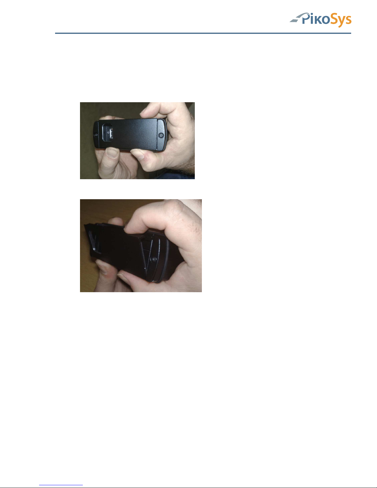
Öffnen Frontklappe PikoLoad
Abbildung 5: Auf Scharnier drücken
Abbildung 6: Frontklappe öffnen
Drücken Sie von unten mit beiden Daumen auf das Scharnier –dann lässt sich die Frontklappe leicht
öffnen.
Achtung: Benutzen Sie keine Gewalt um die Frontklappe zu öffnen !

Funktion und Bedienung PikoLoad
Handbuch / Operation Manual PikoLoad Seite / Page 12 / 35
Version 4
Abbildung 7: Unternehmenskarte einlegen (Chip nach oben)
Achten Sie auf die richtige Lage des Chips (Chip nach oben - siehe Bild) !
Schieben Sie die Unternehmenskarte bis zum Anschlag ein.
Abbildung 8: Eingelegte Unternehmenskarte
Anschließend schließen Sie bitte wieder die Frontklappe.
3.2 Tacho auf Unternehmen sperren
Legen Sie die Unternehmenskarte in den Tacho ein und führen ein Sperren der
Tachodaten auf das Unternehmen durch (siehe Beschreibung Ihres Tachographen)
Anmerkung: Der Tacho muss auf das Unternehmen gesperrt sein, da sonst kein
Datenzugriff gewährt wird

Funktion und Bedienung PikoLoad
Handbuch / Operation Manual PikoLoad Seite / Page 13 / 35
Version 4
3.3 LED-Anzeigen PikoLoad
Abbildung 9: LED-Anzeigen
Die LED’s zeigen folgende Statusinformationen an (Sicht bei USB-Schnittstelle links)
aus aus
Zündung aus
keine Stromversorgung -> Verkabelung prüfen
aus rot
Zündung an
Initialisierung und Selbsttest läuft
rot rot
Fehlerstatus, z.B.
• keine Karte eingelegt -> prüfen
• keine Unternehmenskarte -> prüfen
• Unternehmenskarte falsch eingelegt -> prüfen
• keine CAN-Daten -> Verkabelung überprüfen
-> Tacho prüfen, ob Remote downloadfähig
• USB-Fehler -> USB-Stick prüfen (Formatierung, evtl. USB-Stick voll)
• interner Fehler-> Gerät tauschen
aus grün
Authentisierung läuft oder wird überprüft (Dauer ca. 2 Minuten)
grün grün
Authentisiert, Daten werden geladen
orange grün
USB Stick wird geschrieben, Aufzeichnung läuft weiter
USB-Stick nicht ziehen, da sonst Datenverlust möglich
grün rot
Tacho nicht auf Unternehmenskarte bzw. auf andere Unternehmenskarte
gesperrt
Hinweis: Falls nicht gesperrt werden alle Daten geladen
Fahrerkarten werden unabhängig von der Sperrung geladen
orange rot
Unternehmenskarte abgelaufen (5 Jahre Gültigkeit prüfen)
Unternehmenskarte defekt -> prüfen, ggf. ersetzen
Tacho befindet sich seit mehr als 15 Minuten im „Pending-Modus)
Unternehmenskarte, Kontrollkarte oder Werkstattkarte im Tacho
Tacho wartet auf Eingabe
Interner Tachofehler -> in Werkstatt prüfen lassen
orange orange
„Service Mode“
Funktion und Bedienung PikoLoad
Handbuch / Operation Manual PikoLoad Seite / Page 14 / 35
Version 4
3.4 Datenauswertung
3.4.1 Daten auf USB-Stick auslesen
3.4.2 Beschreibung Dateien USB-Stick
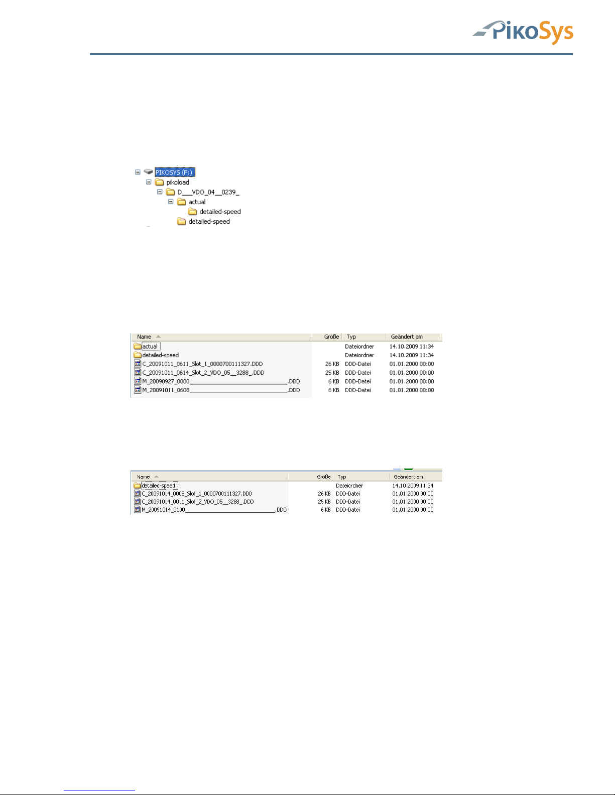
Ordnerstruktur
Abbildung 10: Orderstruktur USB-Stick
Auf dem USB-Stick ist der Ordner „pikoload“ mit dem Unterordner „UnternehmerkartenNummer“ (hier im Beispiel „D___VDO_04__0239_“).
In diesem Unterordner befinden sich die archivierten Dateien für den Massenspeicher und
die Dateien der Fahrerkarten, die mit der im PikoLoad eingelegten Unternehmerkarte vom
Tachographen geladen wurden.
Abbildung 11: Beispieldaten
Im nächsten Unterordner „actual“ befinden sich die bis zuletzt
heruntergeladenen Massenspeicherdaten sowie die zuletzt heruntergeladenen
Dateien der Fahrerkarten. (1 pro Tag und Karte)
Abbildung 12: Beispieldaten
Im „detailed-speed“-Ordner sind die Massenspeicherdaten mit den Geschwindigkeitsdaten
der letzten 24 Stunden (in manchen Ländern Pflicht) gespeichert.
Filestruktur
Massenspeicherdaten:
Filename: M_Datum_Uhrzeit (UTC)_Zulassungsnummer_FahrzeugID.DDD
Beispiel: M_20091014_1213_M-LC 4711_____WAUZ473928744____.DDD
Fahrerkartendaten:
Filename: C_Datum_Uhrzeit(UTC)_Tachoslotnummer_Fahrerkartennummer.DDD
Beispiel: C_20091014_0008_Slot_1_0000700111327.DDD
C_20091014_0011_Slot_2_VDO_05__3288_.DDD
Slot 1 = in der Regel Fahrerslot
Slot 2 = in der Regel Beifahrerslot

Anhang
Handbuch / Operation Manual PikoLoad Seite / Page 15 / 35
Version 4
4 Anhang
4.1 Technische Daten
Abmessungen 119 x 111 x 46 mm
Versorgung 12 V / 24 V über Stecker im Fahrzeug
Schnittstellen 2 x CAN J 1939
1 x USB 2.00
1 x seriell RS 232
Lieferumfang Stecker für Anschluss Fahrzeug
USB-Stick

Anhang
Handbuch / Operation Manual PikoLoad Seite / Page 16 / 35
Version 4
4.2 Steckerbelegungen
4.2.1 CAN 1 Steckerbelegung PikoLoad
1
10
3
12
Abbildung 13: PikoLoad CAN 1 Steckerbelegung
Pin 1 Klemme 31 (Masse)
Pin 6 CAN high (Tachodaten + ggf. FMS-Daten)
Pin 9 CAN low (Tachodaten + ggf. FMS-Daten)
Pin 10 Klemme 15 (24 V DC UBat - Zündung)
Pin 12 Klemme 30 (24 V DC)
Anmerkung: Bitte achten Sie darauf, dass sowohl die Versorgungsspannung als
auch das Zündungssignal verkabelt und angeschlossen ist.
Pin 6 und Pin 9 sind die Verbindungen zum digitalen Tachograph am C-CAN (Pin
5 und Pin 7) Die Anbindung an FMS-Daten ist optional, falls FMS-Daten im
Fahrzeug vorhanden sind!

Anhang
Handbuch / Operation Manual PikoLoad Seite / Page 17 / 35
Version 4
4.2.2 CAN 2 Steckerbelegung PikoLoad
165
10
Abbildung 14: PikoLoad CAN 2 Steckerbelegung
Pin 1 GND
Pin 2 reserviert
Pin 3 CAN high
Pin 4 CAN low
Pin 5 Masse (Ausgang) Klemme 31
Pin 6 12 VDC (Ausgang, optional)
Pin 7 Klemme 15R (‘Ausgang, optional)
Pin 8 Zündung (24V, Ausgang, max. 100mA) Klemme 15
Pin 9 reserviert
Pin 10 24 VDC (Ausgang, max. 5A) Klemme 30
Anmerkung: Zündung ist 24 VDC!
Anmerkung: Dieser CAN hat einen 120 Ohm Abschlusswiderstand! Die
Stromversorgung erfolgt über den grünen Stecker am PikoLoad.
Alle Stromversorgungen am CAN 2 Stecker sind Ausgänge!
Eventuell vorhanden FMS-Daten werden auf die PikoLoad CAN2 Schnittstelle
weitergeleitet.
CAN 2
PikoLoad
Stromversorgung Bordcomputer
Zündungssignal
Ggf. FMS-Daten (CAN)
Abbildung 15: Anschluss PikoLoad CAN 2

Anhang
Handbuch / Operation Manual PikoLoad Seite / Page 18 / 35
Version 4
4.2.3 RS 232 Steckerbelegung am PikoLoad
132
4
Abbildung 16: PikoLoad RS232 Steckerbelegung
Pin 1 GND
Pin 2 RxD
Pin 3 TxD
Pin 4 reserviert
RS 232
PikoLoad
Anschluss Bordcomputer
Abbildung 17: Anschluss PikoLoad RS 232

Anhang
Handbuch / Operation Manual PikoLoad Seite / Page 19 / 35
Version 4
B ENGLISH

Table of Contents
Handbuch / Operation Manual PikoLoad Seite / Page 20 / 35
Version 4
Table of Contents
Table of Contents ................................................................................................... 20
List of Figures ........................................................................................................ 21
1 Introduction ...................................................................................................... 22
1.1 Global..........................................................................................................22
1.2 Functional Description of PikoLoad ..................................................................22
2 Start up ............................................................................................................. 25
2.1 Content of Package PikoLoad ..........................................................................25
2.2 Installation of PikoLoad..................................................................................26
2.2.1 Make up of the FMS wiring (no FMS connector in the vehicle) .................26
2.2.2 Installation in the Vehicle ...................................................................26
2.2.3 Connection to the Tachograph (change of Tacho only) ...........................27
3 PikoLoad ........................................................................................................... 28
3.1 Insertion of the Company Card .......................................................................28
3.2 Lock of the company data at the tachograph ....................................................29
3.3 LED display ..................................................................................................30
3.4 Analyze of data.............................................................................................31
3.4.1 Description of the files on the USB-stick ...............................................31
4 Appendix ........................................................................................................... 32
4.1 Technical Data..............................................................................................32
4.2 Pin Assignment .............................................................................................33
4.2.1 PikoLoad CAN 1 Pin Assignment ..........................................................33
4.2.2 PikoLoad CAN 2 Pin Assignment ..........................................................34
4.2.3 PikoLoad RS 232 Pin Assignment.........................................................35

List of Figures
Handbuch / Operation Manual PikoLoad Seite / Page 21 / 35
Version 4
List of Figures
Figure 1: Make up of FMS wiring ......................................................................................... 26
Figure 2: PikoLoad wiring ................................................................................................... 26
Figure 3: Connection to Tachograph .................................................................................... 27
Figure 4: C-CAN Tachograph Pin Assignment ........................................................................ 27
Figure 5: Press to the hinge................................................................................................ 28
Figure 6: Open Front Lid .................................................................................................... 28
Figure 7: Insert Company Card (Chip up) ............................................................................. 29
Figure 8: Inserted Company Card........................................................................................ 29
Figure 9: LED display ......................................................................................................... 30
Figure 10: Folders on USB-stick .......................................................................................... 31
Figure 11: Example Data.................................................................................................... 31
Figure 12: Example Data.................................................................................................... 31
Figure 13: PikoLoad CAN 1 Pin Assignment........................................................................... 33
Figure 14: PikoLoad CAN 2 Pin Assignment........................................................................... 34
Figure 15: PikoLoad CAN 2 connection ................................................................................. 34
Figure 16: PikoLoad RS232 Pin Assignment .......................................................................... 35
Figure 17: PikoLoad RS connection ...................................................................................... 35

Introduction
Handbuch / Operation Manual PikoLoad Seite / Page 22 / 35
Version 4
1 Introduction
1.1 Global
PikoLoad is a simple, easy to install unit for the automatic download of the mass memory
(and the inserted driver cards) of a digital, remote downloadable tachograph.
With PikoLoad, you can perform the regular downloads of bulk memory required by law
automatically thus avoiding complicated personnel organization and unnecessarily long
download periods. Driver cards are automatically downloaded from the slots of the
tachograph during driving without additional efforts. No training or extensive settings
required. This improves the situation and makes it easier to fulfill the legal requirements –
especially for those vehicles travelling for a long time.
Just insert your company card, connect, ready.
Mass memory and driver card data are easily stored on the USB stick and can be used for
all existing programs for evaluation and post-processing.
PikoLoad has an internal memory to store at least 2 years of the mass memory.
Users of bord computer systems can use the interface to get the downloaded data. No
extensive implementation of the functions for remote download is necessary.
1.2 Functional Description of PikoLoad
The application of PikoLoad offers the following functions:
Authentication of the in PikoLoad inserted company card at the digital tachograph for the
download of the mass memory.
• Configuration of the time period (days) to be downloaded
• Declaration of the data to be downloaded:
o
Overview
o
Activities
o
Technical Data
o
Detailed Speed (24 hours)
o
Events/Faults
o
Inserted driver cards
• Download of the data
• Built of .DDD files for
o
the data of the mass memory
o
the data of the driver cards
• The data are digital signed and are equivalent to the data which can be downloaded on
the standard front connector of the tachograph.
• Output of the data to:
o
USB-stick, if plugged to PikoLoad
o
Second CAN interface of PikoLoad
o
Serial interface of PikoLoad (on request)

Introduction
Handbuch / Operation Manual PikoLoad Seite / Page 23 / 35
Version 4
PikoLoad checks the inserted company card whether it is valid and locked at the
tachograph.
Only those data are downloaded which are locked to the inserted company card. Therefore
it is important to lock the company card at the tachograph before inserting it in the
PikoLoad
Only those data are stored to the USB-stick which are related to the company card
inserted in the PikoLoad. Therefore please let the company card inserted in PikoLoad until
all data are stored on the USB-stick.
If PikoLoad has stored data for several company cards (e.g. PikoLoad is used in more than
one vehicle), you can store them step-by-step to the USB-stick by inserted all company
cards consecutively.
All data of the driver cards which are downloaded with the inserted company card are
stored to the USB-stick. These data are stored with the driver card number only (no
names).
Data are only available on the second CAN interface and on the serial interface of PikoLoad
if a valid company card is inserted. Only those data are available which are related to this
company card.
The driver card data are only available if this driver card is inserted in the tachograph. If
the driver card is removed from the tachograph slot the already started output on
PikoLoad will be finished and afterwards no more driver card information is available.
Please keep in mind that the data on the serial interface are only available on request.
The output of the data on the second CAN of PikoLoad is cyclic.
PikoLoad is loading the following files for the activities:
• First file (= .DDD-file) contains the period from the first use of PikoLoad in this vehicle
until 3 months in the past (if available).
• The next .DDD files contain 14 days each (14 days activities).
• PikoLoad checks whether all data are downloaded until the actual day. Missing days are
downloaded and stored.
The last „not full“ 14 days are also available as .DDD file and contains the activities of the
day until the last 14 days- .DDD file (without the actual day).
This ensures the complete download and storage of the data in PikoLoad.
Please keep in mind that only the data of the actual day are not stored as they are not
fixed until the next day.

Introduction
Handbuch / Operation Manual PikoLoad Seite / Page 24 / 35
Version 4
The maximum period for downloading and storage is dependant on the mass memory
data. However, PikoLoad saves the data for 2 years minimum.
Once a driver card has been successfully authenticated at the tachograph, PikoLoad is
downloading the data from this driver card. If there both slots of the tachograph in use,
PikoLoad is downloading both of them.
Please keep in mind that the download from a driver card at the tachograph needs ca. 2
minutes. After that period the data are available for PikoLoad for download.
Note: The download of a driver card is started every 10 minutes.
The last downloaded driver/Co-driver card is available on the RS232 and
second CAN interface.
The first downloaded driver/CO-driver card is stored on the USB-stick.
The application and functions are based on the official published „user documentation for
Remote Download“ and can be used with remote downloadable, digital tachographs of
Continental, Stoneridge and Actia.
Vehicles with FMS interface
In addition to the download of the mass memory of digital tachographs, FMS data – if
available – are routed and available on the second CAN of PikoLoad. A possible existing
connection to FMS data is not affected by this.
The FMS data are available on request at the serial interface. The last received value will
be available.
Please keep in mind that there is no output to the USB-stick for FMS data.

Start up
Handbuch / Operation Manual PikoLoad Page / Seite 25 / 35
Version 4
2 Start up
2.1 Content of Package PikoLoad
The package consists of the following components:
1 PikoLoad Unit
1 Pikosys USB Sticks
2 connector green 12 pole
1 mounting racket

Start up
Handbuch / Operation Manual PikoLoad Page / Seite 26 / 35
Version 4
2.2 Installation of PikoLoad
2.2.1 Make up of the FMS wiring (no FMS connector in the vehicle)
Make up the FMS wiring in the vehicle (if no standard FMS connector is available).
This step is not necessary if the vehicle has already a standard FMS connector
(green colour).
1.Make up the wiring for the PikoLoad (exact description in the appendix).
Pin 1
Pin 6
Pin 9
Pin 10
Pin 12
FMS-Plug
(female)
Figure 1: Make up of FMS wiring
2.Connect the wiring to the vehicle:
Pin 1 Clamp 31 (ground)
Pin 6 CAN high (C-CAN Tacho Pin 5 + FMS CAN high)
Pin 9 CAN low (C-CAN Tacho Pin 7 + FMS CAN low)
Pin 10 Clamp 15 (24 V DC UBat - Ignition)
Pin 12 Clamp 30 (24 V DC)
2.2.2 Installation in the Vehicle
2.2.2.1 Standard FMS connector existing or made
FMS-Plug
(female)
Pin 1
Pin 6
Pin 9
Pin 10
Pin 12
PikoLoad
Figure 2: PikoLoad wiring
Connect the wiring harness to PikoLoad

Start up
Handbuch / Operation Manual PikoLoad Page / Seite 27 / 35
Version 4
2.2.3 Connection to the Tachograph (change of Tacho only)
Please do this step only if your tachograph has been not factory fitted as
remote download (with green connector)
Connecting Tacho (Example is Continental)
Figure 3: Connection to Tachograph
1
5
4
8
Figure 4: C-CAN Tachograph Pin Assignment
Pin 1 Not used
Pin 2 GND
Pin 3 Not used
Pin 4 Not used
Pin 5 CAN high
Pin 6 Not used
Pin 7 CAN low
Pin 8 Not used
Connect the C-CAN connector (red) to the C-CAN of the tachograph.
Attention: The connectors are coded (fits only to C-CAN)!
Please do not use any other connection to the tachograph! You might disturb the
correct function of the tachograph. Please keep in mind that any work at
tachographs is only allowed by authorized workshops!

PikoLoad
Handbuch / Operation Manual PikoLoad Page / Seite 28 / 35
Version 4
3 PikoLoad
3.1 Insertion of the Company Card
Open the front lid of PikoLoad
Figure 5: Press to the hinge
Figure 6: Open Front Lid
Press the hinge from the button with both thumbs – then the front lid can be
opened easily.
Attention: Do not use force to open the front lid !

PikoLoad
Handbuch / Operation Manual PikoLoad Page / Seite 29 / 35
Version 4
Figure 7: Insert Company Card (Chip up)
Pay attention to the correct position of the chip (chip up – see picture) !
Push up the company card against the end
Figure 8: Inserted Company Card
Please shut the front lid afterwards.
3.2 Lock of the company data at the tachograph
Insert the company card into the tachograph (slot 1) and do the procedure to lock the
data to this company according the description of the tachograph (might vary)
Note: The data have to be locked to the company card otherwise there is no
access granted to the data.

PikoLoad
Handbuch / Operation Manual PikoLoad Page / Seite 30 / 35
Version 4
3.3 LED display
Figure 9: LED display
The LED’s indicate the following status information (USB interface to the left)
off off
Ignition off
No power supply -> check the wiring harness
off red
Ignition on
Initialization and self test is running
red red
Error, e.g.
• No card inserted -> check
• No company card inserted -> check
• Company card wrong inserted -> check
• No CAN-Data -> check wiring harness
-> check tachograph whether remote downloadable
• USB-error -> check USB-stick (Formatting, maybe the USB-stick is full)
• internal error-> replace the unit
off green
Authentication running or is checked (ca. 2 minutes duration)
green green
Authenticated, data are downloading
orange green
USB Stick is in writing mode, download is still running
Do not unplug the USB-Stick, you might loose data
green red
Tacho is not locked to the company card or locked to a different company
card
Note: If not locked, all unlocked data are downloaded
Driver cards are downloaded independent from the lock
orange red
Company card expired (5 years validity check)
Company card damaged -> please check and replace
Tacho is longer than 15 minutes in „pending mode“
Company card, control card or workshop card is inserted in the tachograph
Tacho is waiting on input
Internal Tacho error -> check in workshop
orange orange
„Service Mode“

PikoLoad
Handbuch / Operation Manual PikoLoad Page / Seite 31 / 35
Version 4
3.4 Analyze of data
3.4.1 Description of the files on the USB-stick
Folder structure
Figure 10: Folders on USB-stick
On the USB-stick is the folder „pikoload“ containing the folders „company card
number“ (in the example „D___VDO_04__0239_”).
The archived data of the mass memory and the data from the driver cards which are
downloaded with the inserted company card (in PikoLoad) are saved in this folder
Figure 11: Example Data
The latest downloaded data from the mass memory and the latest downloaded data
from the drivers cards (1 per day and card) are saved in the folder „actual“.
The mass memory with detailed speed (last 24 driving hours) are saved in the
folder „detailed-speed“ (mandatory in some countries).
Figure 12: Example Data
File order
Mass memory data:
Filename: M_Date_Time (UTC)_Registration number_Vehicle ID.DDD
Example: M_20091014_1213_M-LC 4711_____WAUZ473928744____.DDD
Driver card data:
Filename: C_Date_Time(UTC)_Tacho slot number_Driver card number.DDD
Example: C_20091014_0008_Slot_1_0000700111327.DDD
C_20091014_0011_Slot_2_VDO_05__3288_.DDD
Slot 1 = driver slot
Slot 2 = co-driver slot

Appendix
Handbuch / Operation Manual PikoLoad Page / Seite 32 / 35
Version 4
4 Appendix
4.1 Technical Data
Dimensions 119 x 111 x 46 mm
Power supply 12 V / 24 V via plug in vehicle
Interfaces 2 x CAN J 1939
1 x USB 2.00
1 x serial RS 232
Included in package Vehicle connector
USB-Stick

Appendix
Handbuch / Operation Manual PikoLoad Page / Seite 33 / 35
Version 4
4.2 Pin Assignment
4.2.1 PikoLoad CAN 1 Pin Assignment
1
10
3
12
Figure 13: PikoLoad CAN 1 Pin Assignment
Pin 1 Clamp 31 (ground)
Pin 6 CAN high (Tacho data + FMS-Data if available)
Pin 9 CAN low (Tacho data + FMS-Data if available)
Pin 10 Clamp 15 (24 V DC UBat - Ignition)
Pin 12 Clamp 30 (24 V DC)
Note: Please keep in mind that the power supply and the ignition signal is wired
and connected.
Pin 6 and Pin 9 are the connections to the tachograph C-CAN
(Pin 5 and Pin 7)
The connection to FMS data is optional, if FMS data are available in the
vehicle!

Appendix
Handbuch / Operation Manual PikoLoad Page / Seite 34 / 35
Version 4
4.2.2 PikoLoad CAN 2 Pin Assignment
165
10
Figure 14: PikoLoad CAN 2 Pin Assignment
Pin 1 GND
Pin 2 Reserved
Pin 3 CAN high
Pin 4 CAN low
Pin 5 Ground (Out) Clamp 31
Pin 6 12 VDC (Out, optional)
Pin 7 Clamp 15R (Out, optional)
Pin 8 Ignition (24V, Out, max. 100mA) Clamp 15
Pin 9 Reserved
Pin 10 24 VDC (Out, max. 5A) Clamp 30
Note: Ignition is 24 VDC !
Note: This CAN has a 120 Ohm terminating resistor!
The power supply of the PikoTest is via the green connector (CAN 1)
The power supply on CAN 2 is output only!
All FMS data (if available) are routed to the CAN 2 interface of PikoLoad.
CAN 2
PikoLoad
Power supply for bord computer
Ignition
FMS-Data (CAN) if available
Figure 15: PikoLoad CAN 2 connection

Appendix
Handbuch / Operation Manual PikoLoad Page / Seite 35 / 35
Version 4
4.2.3 PikoLoad RS 232 Pin Assignment
132
4
Figure 16: PikoLoad RS232 Pin Assignment
Pin 1 GND
Pin 2 RxD
Pin 3 TxD
Pin 4 Reserved
RS 232
PikoLoad
Connection to bord computer
Figure 17: PikoLoad RS connection
 Loading...