

Page 1

35040
R/C Sender
und Empfänger
1. Allgemeine Informationen
Vielen Dank für den Kauf des PIKO R/C Systems für den Funkbetrieb von Gartenbahnmodellen.
Bitte lesen Sie diese Bedienungsanleitung sorgfältig durch, um
alle Funktionen dieses Gerätes nutzen zu können. Beachten Sie
unbedingt unsere nachfolgenden Sicherheits- und Warnhinweise,
um einen störungsfreien und sicheren Betrieb Ihres Modells zu
gewährleisten.
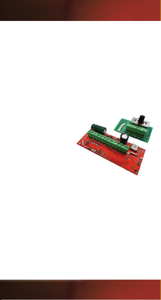
Mit diesem Set können Sie eine analoge Lokomotive für den Funkbetrieb umrüsten. Bestehend aus der Hauptleiterplatte (Empfänger), einer Schalterplatte und einem Sender (Fernbedienung)
erhält man alle Komponenten für den Funkbetrieb. Es besteht
die Möglichkeit das System mit Batteriespannung* oder mit
permanenter Gleisspannung zu versorgen. Zusätzlich sind zwei
Schaltfunktionen / Soundfunktionen (abhängig von der Lokausstattung) schaltbar.
2. Sicherheits- & Warnhinweise
Die Fernsteuerung ist ausschließlich für den Einsatz in
Modellbahnen konzipiert. PIKO übernimmt keinerlei Haftung im
Falle einer anderen Verwendung. Ferngelenkte Modelle sind kein
Spielzeug und erst für Modellbahner ab 14 Jahren geeignet. Der
Bau und Betrieb solcher Modelle erfordert spezielle Kenntnisse,
handwerkliche Sorgfalt, technisches Verständnis und ein umsichtiges, sicherheitsbewusstes Verhalten. Fehler bei der Montage
oder beim Betrieb können erhebliche Sach- und Personenschäden
verursachen. PIKO übernimmt keinerlei Haftung für Schäden, die
durch den unsachgemäßen Betrieb unserer Produkte entstehen.
Technische Defekte elektrischer oder mechanischer Art können
zum unverhofften Anlaufen eines Motors führen, die bei Ihnen und
*Batterien bzw. Batteriehalter sind nicht im Set enthalten.
Page 2
umstehenden Personen zu erheblichen Verletzungen führen können! Auch ein Betrieb der Empfangsanlage ohne aktivierten Sender
kann zu diesem Effekt führen. Schützen Sie Ihre Fernsteueranlage
vor Staub, Schmutz und Feuchtigkeit. Setzen Sie die Geräte keiner
übermäßigen Hitze, Kälte oder Vibration aus. Der Fernsteuerbetrieb
darf nur im angegebenen Temperaturbereich von –15°C bis +55°C
durchgeführt werden. Vermeiden Sie Stoß- und Druckbelastung.
Überprüfen Sie Ihre Fernsteuerung stets auf Beschädigungen an
Gehäusen, Kabeln und Anschlüssen.
3. Lieferumfang:
1x Sender (Fernbedienung)
1x Empfänger (Hauptleiterplatte)
1x Leiterplatte mit Schalter
1x Kabel (grau-weiß; 2-polig)
3.1 Technische Daten
SENDER (Fernbedienung)
Anzahl Kanäle: 8
Frequenzband: 2,4 GHz
Reichweite: ca. 30 m
Spannungsversorgung: 1x 3 V CR2025
Abmessungen: ca. 68 x 36 x 16 mm
Gewicht: ca. 30 g
EMPFÄNGER (Hauptleiterplatte)
Anzahl Kanäle: 8
Fahrstufen: 14 (bei 7-16 V) 28 (bei 16-24 V)
Frequenzband: 2,4 GHz
Reichweite: ca. 30 m
Spannungsversorgung: 7 - 24 V DC / 6 - 18 V AC
max. Ausgangsstrom: 3A
Abmessungen: ca. 69 x 29 x 15 mm
Gewicht: ca. 40 g
2
Page 3
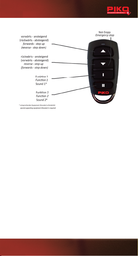
4. Bedienelemente
5. Inbetriebnahme
Der Sender benötigt für den Betrieb eine CR2025 Batterie. Am
oberen Ende der Fernbedienung be ndet sich eine LED, die jede
Betätigung bestätigt. Lässt die Leuchtkraft, bzw. die Reichweite der
Fernbedienung nach, müssen Sie die Batterie ersetzen.
Gehen Sie dabei wie folgt vor:
• Den Deckel zum Einlegen der Zelle an der Vertiefung aufhebeln.
• Setzen Sie die Knopfzelle vorsichtig mit dem Pluspol nach oben in
die Halterung ein.
• Legen Sie den Metallbügel wieder in die Gehäuseunterseite und
fügen Sie die beiden Gehäusehälften zusammen.
6. Anschlüsse am Empfänger
ACHTUNG! Es muss unbedingt auf die korrekte Polung der Versor-
gungsspannung geachtet werden.
Über eine Schraubklemme werden die vorhandenen Kabel angeschlossen.
Damit der Empfänger die Signale empfangen kann, muss er mit
dem entsprechenden Sender verbunden werden. Dies geschieht
durch eine einfache Kanalwahl mittels eines DIP-Drehschalters.
3
Page 4
6.1 Einbau
Batterie
7-24 V DC
INPUT B
permanent
Licht vorne
Licht hinten
Innenbel. / Zubehör / permanent
Sound 2 / Funktion 2 (Reedkontakt)
Sound 1 / Funktion 1 (Reedkontakt)
Analogsoundmodul * (S2)
Analogsoundmodul * (S1)
Motor (M2)
Motor (M1)
Empfänger
Schalter
Spannung vom Gleis
(Gleiskontakt Lok)
12 - 22 V AC / DC
INPUT A
aus
an
A
an B* z.B. #36194 PIKO G Sound Kit (analog)
Batterie
7-24 V DC
INPUT B
permanent **
Sound 2 / Funktion 2 (Reedkontakt)**
Sound 1 / Funktion 1 (Reedkontakt)**
Sound-Decoder * (S2/RR)
Sound-Decoder * (S1/LR)
Empfänger
Schalter
Spannung vom Gleis
(Gleiskontakt Lok)
12 - 22 V AC / DC
INPUT A
aus
an
A
an
B
* z.B. in PIKO US Loks; #36220 PIKO G Sound-Decoder
** siehe Anschlussplan des Decoders, bzw. der Lok
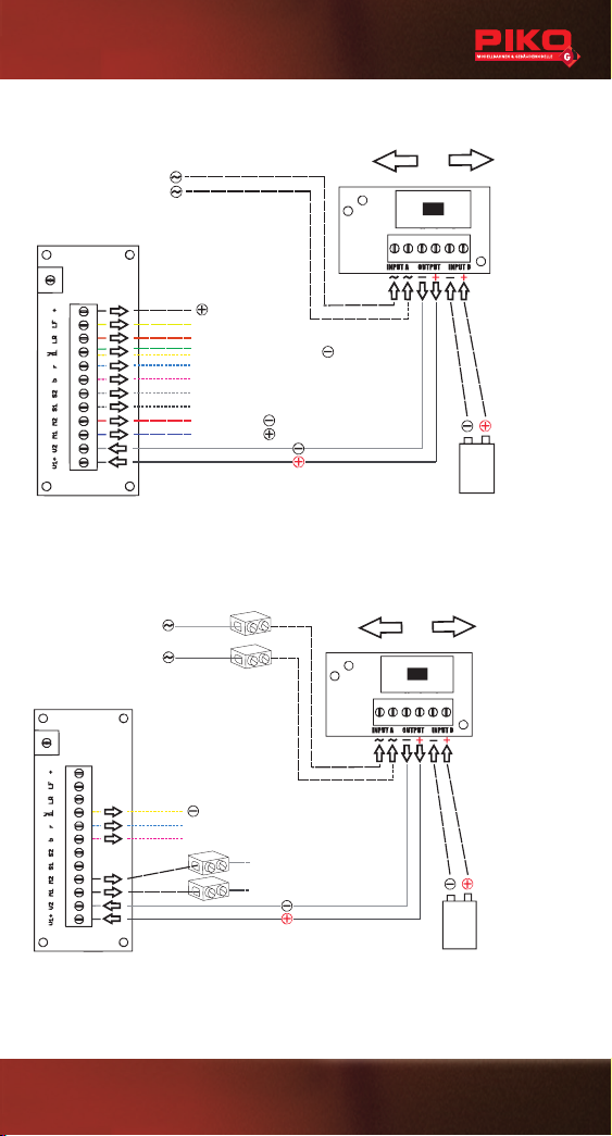
Der Einbau der Leiterplatten ist individuell vom Modell und von der
Ausstattung abhängig. Die Hauptplatine hat die gleichen Maße,
wie unsere Standardleiterplatte, bzw. Decoder. Somit kann der
vorhandene Platz verwendet werden. Üblicherweise tauscht man
die vorhandene Hauptleiterplatte mit der neuen R/C-Leiterplatte
aus. Für die Schalterleiterplatte muss ein geeigneter Platz gefunden
werden. Wichtig ist, dass die Lötstellen der Leiterplatten keinen
Kontakt zu Metallteilen in der Lok haben, da sonst Kurzschlüsse die
Folge sind.
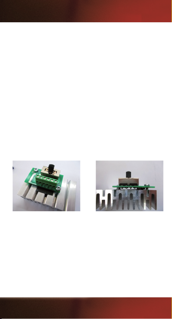
ACHTUNG! Bei Verwendung des Systems mit permanenter
Gleisspannung, muss die Schalterleiterplatte fachgerecht auf
einem Metallgewicht montiert werden, einerseits zur Kühlung des
Gleichrichters und andererseits zum Schutz vor Beschädigung
durch heiße Teile. Dabei aber bitte auf entsprechende Isolierung
der Lötstellen achten!
Es ist möglich, die R/C Leiterplatte mit dem Analogsoundmodul
bzw. Sounddecoder zu verbinden. Dabei müssen die bestehenden
Versorgungsleitungen evtl. getrennt und entsprechend erweitert
werden. Die folgenden Abbildungen zeigen diverse Möglichkeiten.
ACHTUNG! Diese Arbeitsschritte sollten nur von erfahrenen
Modellbahnern durchgeführt werden.
4
Page 5
6.1.1 Direkter Einbau
Batterie
7-24 V DC
INPUT B
permanent
Licht vorne
Licht hinten
Innenbel. / Zubehör / permanent
Sound 2 / Funktion 2 (Reedkontakt)
Sound 1 / Funktion 1 (Reedkontakt)
Analogsoundmodul * (S2)
Analogsoundmodul * (S1)
Motor (M2)
Motor (M1)
Empfänger
Schalter
Spannung vom Gleis
(Gleiskontakt Lok)
12 - 22 V AC / DC
INPUT A
aus
an
A
an
B
* z.B. #36194 PIKO G Sound Kit (analog)
Batterie
7-24 V DC
INPUT B
permanent **
Sound 2 / Funktion 2 (Reedkontakt)**
Sound 1 / Funktion 1 (Reedkontakt)**
Sound-Decoder * (S2/RR)
Sound-Decoder * (S1/LR)
Empfänger
Schalter
Spannung vom Gleis
(Gleiskontakt Lok)
12 - 22 V AC / DC
INPUT A
aus
an
A
an
B
* z.B. in PIKO US Loks; #36220 PIKO G Sound-Decoder
** siehe Anschlussplan des Decoders, bzw. der Lok
5
Page 6
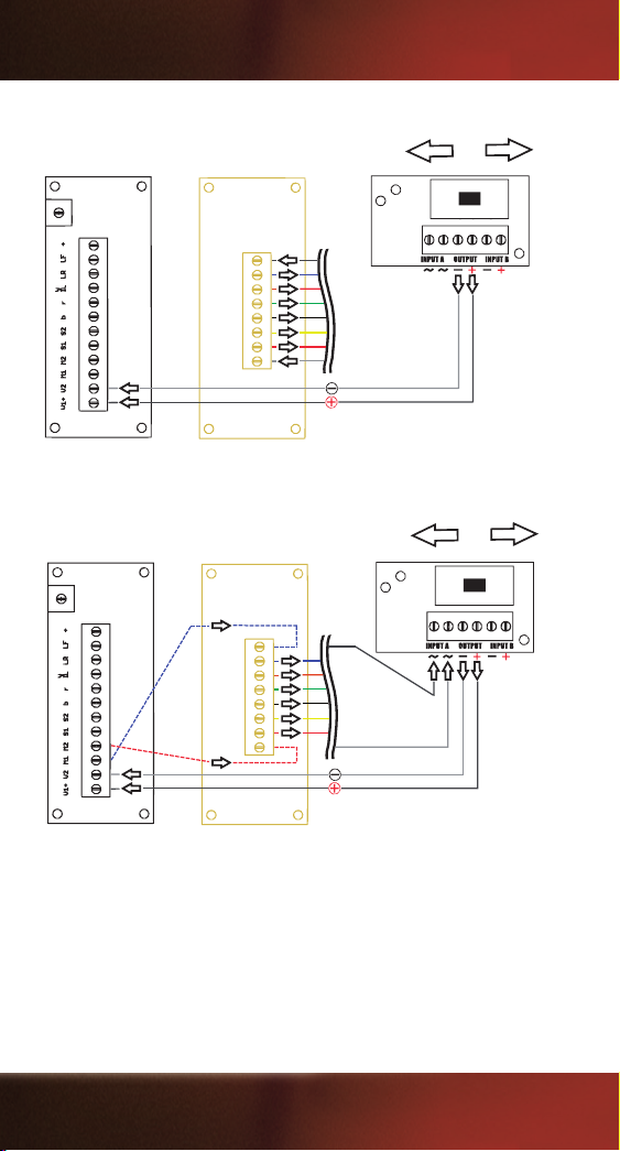
6.1.2 Paralleler Einbau
Empfänger
Schalter
aus
an
aus
Schritt 1
PIKO G
analog
Platine*
* Standard in vielen PIKO G-Lokomotiven. Siehe Anschlussplan Lok.
Schalter
aus
an
Empfänger
aus
Schritt 2
PIKO G
analog
Platine*
* Standard in vielen PIKO G-Lokomotiven. Siehe Anschlussplan Lok.
6
Page 7
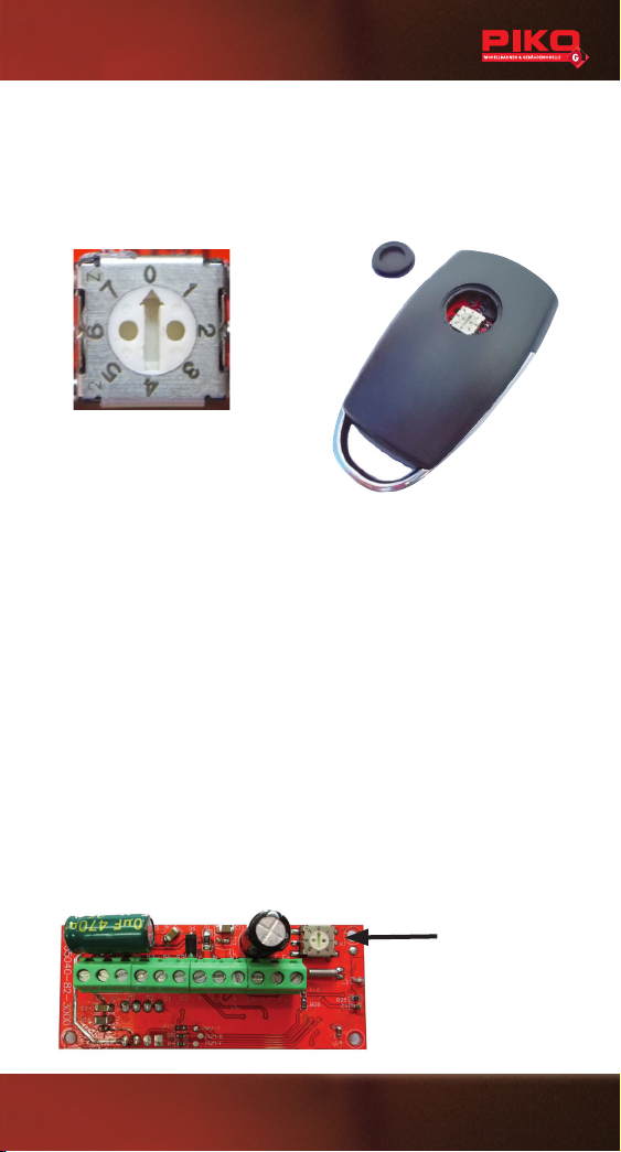
7. Kanalwahl / Synchronisation
Damit der Empfänger die Signale des Senders empfangen kann,
muss er mit dem entsprechenden Sender verbunden werden.
Dies geschieht durch eine einfache Kanalwahl mittels eines DIPDrehschalters.
Werksseitig sind Sender und
Empfänger auf Kanal 0 eingestellt.
Sender:
1. Nehmen Sie am Sender die kleine Abdeckung an der Rückseite
ab.
2. Sie haben nun Zugriff auf den DIP-Drehschalter.
3. Durch die Pfeilrichtung wird der eingestellte Kanal angezeigt.
4. Durch Drehen mit einem kleinen, achen Schraubendreher
können Sie den Kanal einstellen. Sender und Empfänger müssen
so entsprechend auf einander synchronisiert werden.
Empfänger:
1. Je nach Einbauposition benötigen Sie Zugriff auf den DIP-
Drehschalter auf der Hauptleiterplatte
2. Durch Pfeilrichtung wird der eingestellte Kanal angezeigt.
3. Wie schon am Sender, stellen Sie am DIP-Drehschalter den
Kanal, mit einem kleinen, achen Schraubendreher, ein.
DIP
7
Page 8
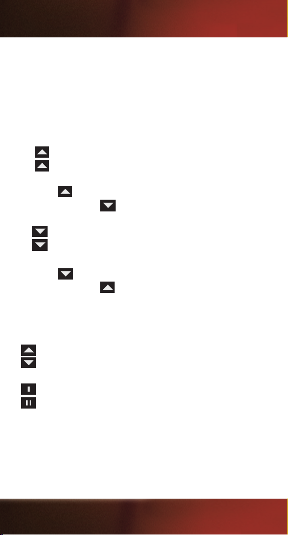
8. Bedienung
Stellen Sie zunächst sicher, dass Sie die Schalterplatine
eingeschaltet haben! (siehe Abb. 6.1.1, Seite 5)
Die Bedienung ist simpel aufgebaut. Durch Betätigung der Tasten
an der Fernbedienung wählen Sie die Fahrtrichtung/Fahrstufe
und können je nach Funktionsumfang / Zubehör sogar zwei
Soundfunktionen auslösen*.
= Fahrtrichtung vorwärts, Fahrstufe 1
1 x
= Fahrtrichtung vorwärts, Fahrstufe 2
2 x
Wenn Sie bereits mit der Lok vorwärts fahren, können Sie mit
der Taste
Betätigung der Taste
1x
2x
die Geschwindigkeit (Fahrstufen) erhöhen. Durch
reduzieren Sie die Geschwindigkeit.
= Fahrtrichtung zurück, Fahrstufe 1
= Fahrtrichtung zurück, Fahrstufe 2
Wenn Sie bereits mit der Lok rückwärts fahren, können Sie mit
der Taste
Betätigung der Taste
die Geschwindigkeit (Fahrstufen) erhöhen. Durch
reduzieren Sie die Geschwindigkeit.
Sie können die Tasten kurz betätigen, was je nur eine Fahrstufe
ändert, oder Sie können die Tasten gedrückt halten, was eine
kontinuierliche Änderung der Geschwindigkeit bewirkt.
}
= Not-Stopp
= Soundauslösung 1, z.B. eine Glocke*
= Soundauslösung 2, z.B. eine Pfeife*
Anmerkung zum Fahrverhalten:
Das Anfahrverhalten (niedrige Fahrstufen) ist vom Zustand und vom
Aufbau der Lok abhängig. Es kann sein, dass die Pfeiltasten mehrmals
betätigt werden müssen, bevor die Lok zu fahren beginnt. Loks mit
eingebautem Decoder fahren generell erst bei höheren Fahrstufen an.
8
*Nur in Verbindung mit entsprechendem Zubehör mit Reedkontakt-Auslösung.
Page 9

35040
R/C Loco Receiver, 3A,
with Pocket Remote
1. General information
Thank you for purchasing the PIKO R/C system for radio operation.
of garden railway models.
Please read these operating instructions carefully in order to be
able to use all the functions of this device. It is essential that you
observe the following safety and warning instructions to ensure
trouble-free and safe operation of your model.
With this set you can retrot an analogue locomotive for radio
operation. With the main circuit board (receiver), a switch plate
and a transmitter (remote control), you receive all the components
for radio operation. It is possible to supply the system with battery
voltage* or permanent track voltage. In addition, two switching functions / sound functions (depending on the locomotive equipment)
are switchable.
*Batteries or battery holders are not included in the set.
2. Safety & warning information
The remote control system has been designed and approved exclusively for the control of RC models. PIKO Modellbau assumes no
liability in the event of any other use. Remote-controlled models are
not toys and only suitable for model railroaders aged 14 and over.
The construction and operation of such models requires special
knowledge, technical care, technical understanding and careful,
safety-conscious behaviour. Errors during assembly or operation
can cause considerable damage to property and personal injury. As
manufacturers and sellers, we are unable to monitor the operation
of our products. Therefore we do not assume any liability. Technical
defects of an electrical or mechanical nature can lead to the
unexpected starting of a motor, which can seriously injure not only
you! Even an operation of the receiver system without activated
9
Page 10
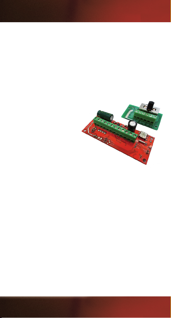
transmitter can lead to this effect. Protect your remote control
system from dust, dirt and moisture. Do not expose the devices to
excessive heat, cold or vibration. The remote control operation may
only be carried out in the specied temperature range from -15°C to
+55°C. Avoid shock and pressure loads. Always check your remote
control for damage to housings, cables and connections.
3. Content:
1x Transmitter (Pocket remote)
1x Receiver (main PCB)
1x PCB with switch
1x Cable (2-pole, gray-white)
3.1 Technical data
Transmitter (Pocket Remote)
Number of channels: 8
Frequency range: 2.4 GHz
Range approx.: 30 m
Power supply: 1x 3 V CR2025
Dimensions approx.: 2.68“ x 1.42“ x 0.63“ (68 x 36 x 16 mm)
Weight approx.: 30 g
Receiver (Main PCB)
Number of channels: 8
Speed steps: 14 (bei 7-16 V) 28 (bei 16-24 V)
Frequency range: 2.4 GHz
Range approx.: 30 m
Power supply: 7 - 24 V DC / 6 - 18 V AC
max. current: 3A
Dimensions approx.: 2.72“ x 1.14“ x 0.59“ (69 x 29 x 15 mm)
Weight approx.: 40 g
10
Page 11
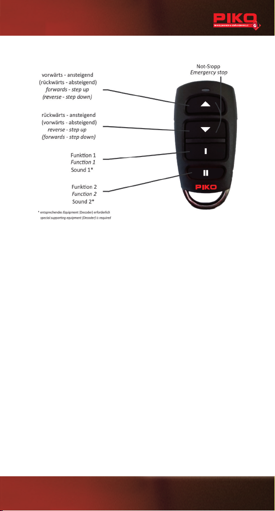
4. Control elements
5. First set-up
The transmitter requires a CR2025 battery for operation. There is
a LED at the top of the remote that con rms each operation. If the
brightness or range of the remote control decreases, the
battery must be replaced.
Proceed as follows:
• To insert the cell, lever open the lid with a coin on the recess.
• Carefully insert the button cell into the holder with the plus pole
facing up.
• Place the metal bracket back into the bottom of the housing and
join the two halves of the housing together.
6. Connections on the receiver
ATTENTION: The correct polarity of the supply voltage must be
observed. The existing cables are connected via a screw terminal.
So that the receiver can receive the signals from the transmitter,
it must be connected to the appropriate transmitter. This
is done by a simple channel selection via a DIP turn switch.
11
Page 12
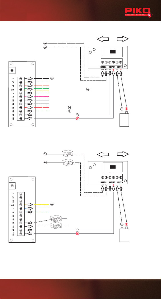
6.1 Installation
Battery
7-24 V DC
INPUT B
permanent
Light front
Light rear
Interior l. / equipment / permanent
Sound 2 / function 2 (Reed contact)
Sound 1 / function 1 (Reed contact)
Analog sound modul * (S2)
Analog sound modul * (S1)
Motor (M2)
Motor (M1)
Receiver
Switch
Voltage from track
(Rail contact loco)
12 - 22 V AC / DC
INPUT A
off
on
A
on
B
* e.g. #36194 PIKO G Sound Kit (analog)
Battery
7-24 V DC
INPUT B
permanent **
Sound 2 / function 2 (Reed contact)**
Sound 1 / function 1 (Reed contact)**
Sound-Decoder * (S2/RR)
Sound-Decoder * (S1/LR)
Receiver
Switch
Voltage from track
(Rail contact loco)
12 - 22 V AC / DC
INPUT A
off
on
A
on
B
The installation of the circuit boards depends individually on the
model and the equipment. The main board has the same dimensions as our standard circuit board or decoder. Thus the available
space can be used. Usually the existing main board is replaced with
the new R/C board. A suitable place must be found for the switch
circuit board. It is important that the solder joints of the printed
circuit boards are not in contact with metal parts in the locomotive,
otherwise short circuits will result.
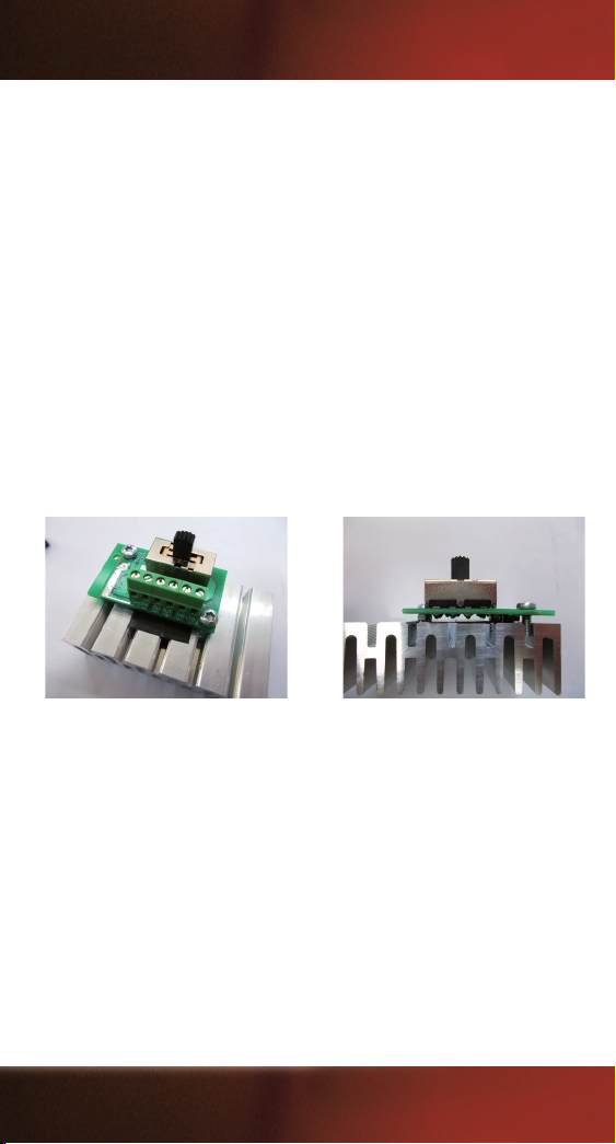
ATTENTION! If the system is used with permanent track voltage,
the switch PCB must be properly mounted on a metal weight. On
the one hand to cool the rectier and on the other hand to protect
it from damage by hot parts. However, make sure that the solder
joints are properly insulated!
The experienced modeler will integrate the R/C circuit board to the
analog sound or sound decoder. The existing supply lines must
be separated and extended accordingly. The following illustrations
show the possibilities.
Attention! These steps should only be carried out by experienced model railroaders.
12
Page 13
6.1.1 Direct installation
Battery
7-24 V DC
INPUT B
permanent
Light front
Light rear
Interior l. / equipment / permanent
Sound 2 / function 2 (Reed contact)
Sound 1 / function 1 (Reed contact)
Analog sound modul * (S2)
Analog sound modul * (S1)
Motor (M2)
Motor (M1)
Receiver
Switch
Voltage from track
(Rail contact loco)
12 - 22 V AC / DC
INPUT A
off
on
A
on B* e.g. #36194 PIKO G Sound Kit (analog)
Battery
7-24 V DC
INPUT B
permanent **
Sound 2 / function 2 (Reed contact)**
Sound 1 / function 1 (Reed contact)**
Sound-Decoder * (S2/RR)
Sound-Decoder * (S1/LR)
Receiver
Switch
Voltage from track
(Rail contact loco)
12 - 22 V AC / DC
INPUT A
off
on
A
on
B
13
Page 14
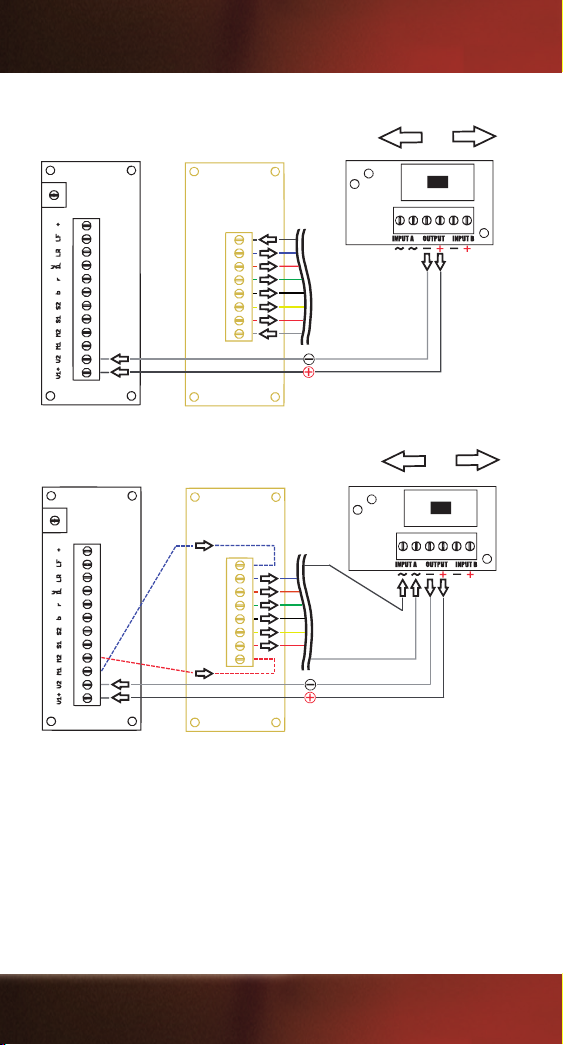
6.1.2 Parallel installation
Receiver
Switch
off
on
off
Step 1
PIKO G
analog
board*
Switch
off
on
Receiver
off
Step 2
PIKO G
analog
board*
* Fitted as standard in many PIKO G-scale locos. See in the locos instruction manual.
14
Page 15
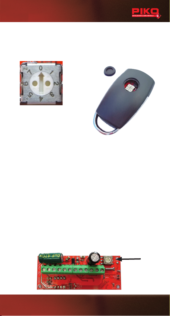
7. Channel selection / Synchronization
In order for the receiver to pick up the signals from the transmitter, it
must be connected to the corresponding transmitter This is done by
simply selecting a channel using a DIP rotary switch.
The transmitter and receiver are
factory-set to channel 0.
Transmitter:
1. Remove the small cover on the
back of the transmitter.
2. You now have access to the DIP rotary switch.
3. The arrow direction indicates the set channel.
4. You can adjust the channel by turning it with a small at
screwdriver. Transmitter and receiver must be synchronized
accordingly.
Receiver:
1. Depending on the installation position, you need access to the
DIP turn switch on the main circuit board
2. The direction of the arrow indicates the channel that has been
set.
3. As with the transmitter, use a small at screwdriver to set the
channel on the DIP turn switch.
Transmitter and receiver must therefore be synchronized
accordingly.
DIP
15
Page 16
8. Operation
First make sure that you have switched on the switch board!
The operation is simple. By pressing the buttons on the remote
control, you can select the direction of travel/speed level and,
depending on the range of functions/further accessories, even
trigger 2 sound functions*.
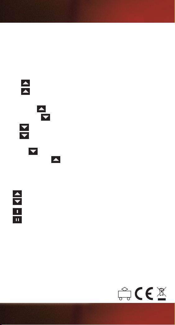
1 x
= Forward driving direction, speed level 1
= Forward driving direction, speed level 2
2 x
If you are already driving forwards with the locomotive, you can use
the button
By pressing
1x
2x
to increase the speed (speed levels).
, you can decrease the speed.
= Reverse driving direction, speed level 1
= Reverse driving direction, speed level 2
If you are already reversing with the locomotive, you can use the
button
Press the button
to increase the speed (speed steps).
to reduce the speed.
You can press the buttons brie y, which only changes one speed
step at a time, or you can keep the buttons pressed, which causes
the speed to change continuously.
}
= Emergency stop
= Sound triggering 1, e.g. a bell*
= Sound triggering 2, e.g. a horn*
*Only in combination with appropriate accessories with Reed contact tripping.
REGULATORY INFORMATION
FCC ID: 2ATRN-35041
FCC Information (USA):
This device complies with part 15 of the FCC Rules. Operation is subject
to the following two conditions: (1) This device may not cause harmful
interference, and (2) this device must accept any interference received,
including interference that may cause undesired operation.
35040-90-7000 © 2019, PIKO Spielwaren GmbH
PIKO Spielwaren GmbH · Lutherstr. 30 · 96515 Sonneberg, GERMANY
 Loading...