

Page 1
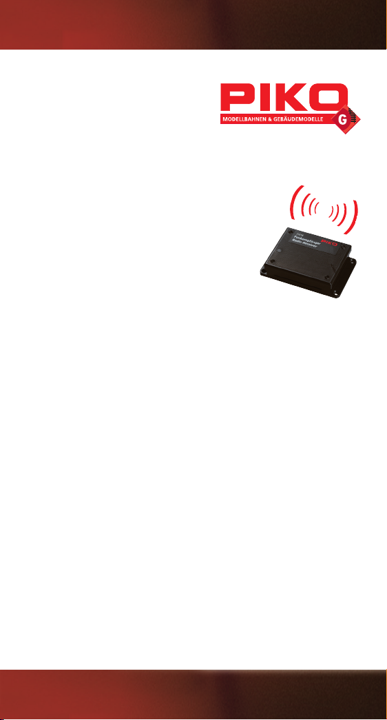
35018
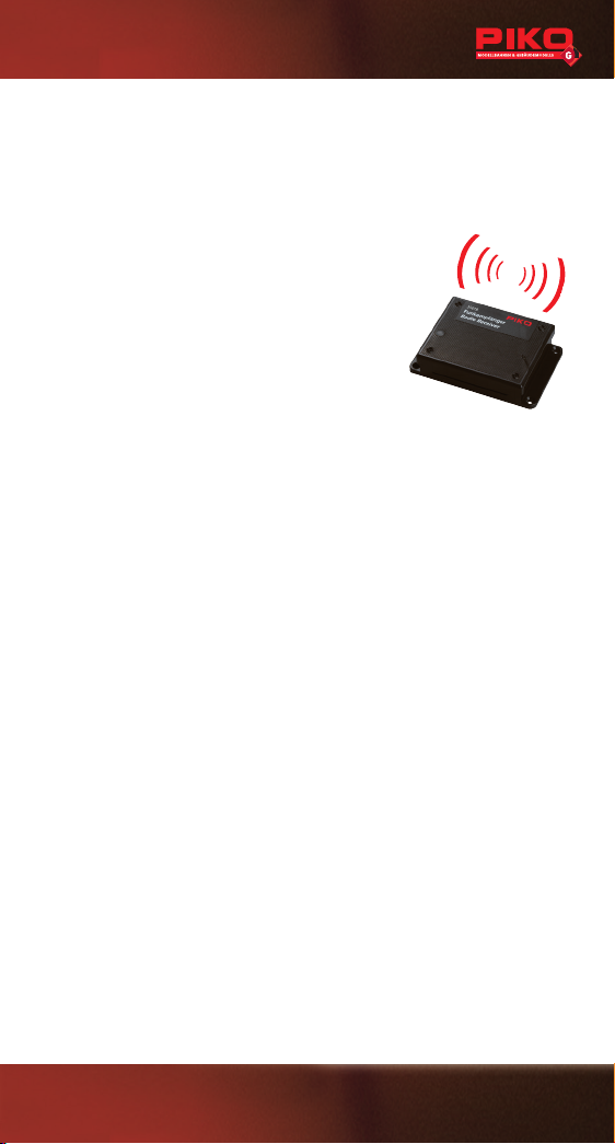
Funkempfänger
2,4 GHz
1. Technische Daten:
• Versorgungsspannung 5...24 V DC (je nach Zentrale oder Regler)
• Stromaufnahme 30 mA im Ruhezustand
• Frequenzband 2.402...2.480 GHz
• Sendeleistung max. 10 mW typ 1 mW 0-9,5 dBm
• Temperaturbereich -20 ... +45°
• Abmessungen (L x B x H) 95 x 64 x 23 mm
1.1 Lieferumfang:
• Funkempfänger
• Buskabel Digital (6-polig) + Buskabel Analog (8-polig)
• Bedienungsanleitung
2. Kurzbeschreibung
Der PIKO Funkempfänger wandelt die Funkdaten des PIKO Navigators in analoge oder
digitale Signale für den PIKO Analogfahrregler oder die PIKO Digitalzentrale um. Durch
seine 2,4 GHz-Funktechnik arbeitet er weitestgehend störungssicher. Die Reichweite
ist von den örtlichen Gegebenheiten abhängig. Fremde Sender auf gleicher Frequenz
sowie Hindernisse zwischen Sender und Empfänger (z.B. Wände) können den Funkverkehr einschränken. Der Anschluss erfolgt über eines der beiden Buskabel.
Der Funkempfänger ist wettergeschützt im Gehäuse montiert. Es empehlt sich allerdings bei Verwendung im Freien die geschützte Montage, zum Beispiel unter einem
Modellbahngebäude, um die empndliche Elektronik zu schützen.
2.1 Anschluss:
Öffnen Sie das Gehäuse über die 4 Schrauben im Deckel und nehmen diesen ab.
Nehmen Sie die Leiterplatte vorsichtig aus dem Gehäuse und legen sie auf eine stabile, rutschfeste und elektrisch nicht leitende Unterlage, z.B. ein Mousepad. Stecken Sie
das benötigte Kabel mit den Kontaktächen nach oben zeigend in die entsprechende
Buchse. Dem Funkempfänger #35018 liegen zwei Anschlusskabel (1x analog 8-polig
für #35002 und 1x digital 6-polig für #35010) bei.
Bitte schließen Sie nur eines der beiden Kabel an. Es werden nicht beide
Betriebsarten (analog und digital) gleichzeitig unterstützt.
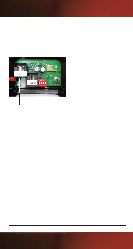
Achtung: Das Analogdatenkabel ist 8-polig und breiter als das 6-polige
Digitaldatenkabel. Bitte vergewissern Sie sich, dass Sie nicht das kleinere Kabel
in die Analogbuchse einstecken, da sonst die Funktion beeinträchtigt, bzw. die
Analogbuchse beschädigt wird! (siehe Bild 1).
1
Page 2
Um das eingesteckte Kabel wieder zu lösen, müssen Sie zuerst den kleinen Verrastungshebel am Stecker drücken und dabei den Stecker aus der Buchse ziehen.
Legen Sie die Leiterplatte wieder vorsichtig in das Gehäuse ein. Schließen Sie das
Gehäuse und verschrauben Sie den Deckel mit einem geeigneten Schraubendreher.
Überprüfen Sie, ob das Kabel gut verlegt ist und die Dichtung des Funkempfängers gut anliegt. Schließen Sie nun das Kabel an die Digitalzentrale bzw. an den
Fahrregler an. (siehe betreffende Bedienungsanleitung)
Analoganschluss
Bild 1: Anschlussmöglichkeiten am Funkempfänger
(für #35002)
Digitalanschluss
(für #35010)
DIP-Schalter Anmeldetaste
2.2 Montage:
Der Funkempfänger kann über 4 Bohrungen im Gehäuse auf einem entsprechenden
Untergrund befestigt werden.
2.3 Betriebszustand:
Im eingeschalteten Ruhezustand blinkt die rote LED (lang an, lang aus) und
zeigt damit an, dass noch keine Verbindung zu einem Funkhandregler besteht.
Sobald ein Funkhandregler erkannt wird, leuchtet die LED dauerhaft und zeigt normalen Betrieb an. Beim erstmaligen Betrieb, nach einem Werksreset oder wenn ein
neues Gerät über den Taster angemeldet werden soll, blinkt die LED symmetrisch
schnell. Der Funkempfänger kann mit bis zu vier Digitalhandreglern gleichzeitig
betrieben werden.
Betriebszustand der STATUS LED
An (dauerhaft) Regulärer Betrieb mit einem oder mehreren
Funksendern
Blinken (symmetrisch schnell) Empfänger sucht nach neuem Teilnehmer z. B.
beim ersten Einschalten, nach Werksreset oder
wenn ein neues Gerät über den Taster angemeldet werden soll.
Blinken (symmetrisch langsam) Funkempfänger „Standby“ - nach dem Ein-
schalten oder wenn längere Zeit kein Sender
aktiv ist.
2
Page 3
2.4 Positionierung und Reichweite:
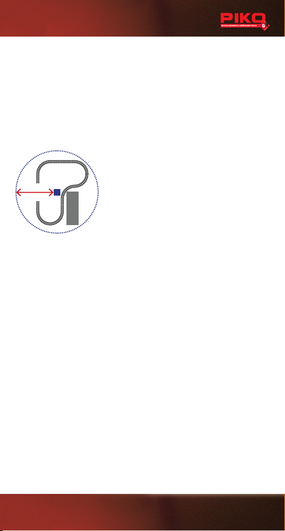
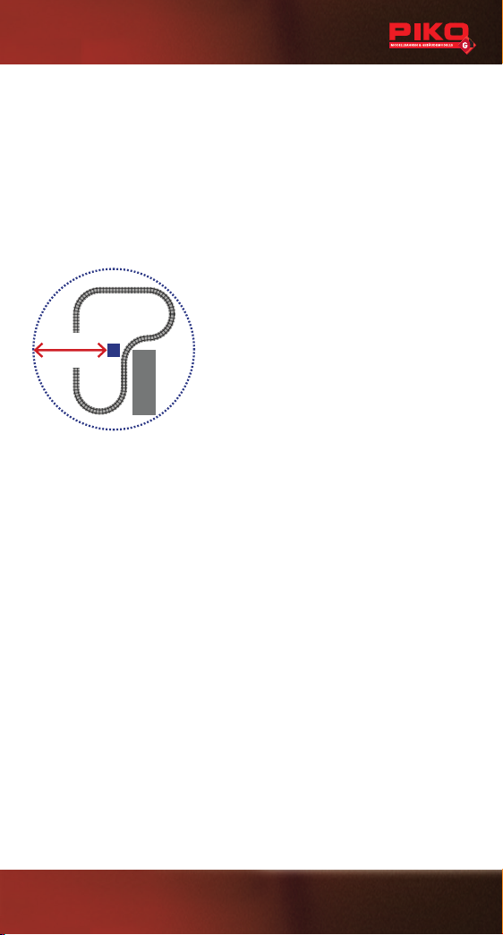
Die Reichweite des Funkempfängers beträgt ca. 50 Meter. Die Reichweite ist stark
von örtlichen Gegebenheiten abhängig. Andere Sender auf gleicher Frequenz wie z.B.
Garagentüröffner, Funkthermometer, Funkkopfhörer, Funkmäuse oder Funktastaturen,
sowie Hindernisse zwischen Sender und Empfänger oder Wände können die Funkreichweite teilweise stark einschränken. Stellen Sie den Funkempfänger so auf, dass die
Reichweite von keinem Punkt Ihrer Anlage aus überschritten wird. Der Empfänger sollte
mindestens 1 Meter Abstand zu Netzteilen, Digitalzentrale und Gleisen haben. Verlegen
Sie das Buskabel nicht parallel zu den Gleisen. Probieren Sie ggf. mehrere Positionen
aus, um den optimalen Standort zu ermitteln.
35018
ca. 50m
ca. 164ft
Haus
House
Bild 2: Positionierung und Reichweite
3. Funkverbindung herstellen
Stellen sie sicher, dass sie einen Navigator mit dem 2,4 GHz-Funksystem verwenden. Die Erstanmeldung (oder Neuanmeldung nach einem Reset) erfolgt in der
Regel automatisch. Sollte dies nicht der Fall sein, müssen Sie lediglich den Naviga-
tor in den Verbindungsmodus bringen. Die Einstellungen hierzu nden sie im Menü
Ihres PIKO 2,4 GHz Navigators.
Für weitere Anmeldungen unter Funksender Kong oder wenn die Erstanmeldung
nicht erfolgreich war, drücken sie den Taster am Empfänger ca. 10 Sekunden bis
die Status-LED schnell symmetrisch blinkt. Während des Blinkens können sie einen
weiteren Navigator anmelden. Bereits angemeldete Funkteilnehmer können sich
ohne Anmeldung wieder einloggen. Sofern dies nicht funktioniert, ist entweder die
Verbindungsliste voll (mehr als acht Sender in der Liste) oder ein Reset wurde vorgenommen.
Aus der Verbindungsliste des Systems wird immer der älteste, als „Standard“ angemeldete Navigator gelöscht. Bis zu zwei Navigatoren können vor dem Entfernen aus
der Verbindungsliste gesichert werden. Hierfür muss im Menü Ihres PIKO 2,4 GHz
Navigators unter Funksender Kong --> LogIn 2.4 die Option Pri (für „Priorität“) ausgewählt werden.
4. ID - Identikationsnummer
Der Funkempfänger ist passiv und verfügt über keine vom Nutzer einzustellende ID.
Mit der Anmeldung eines Navigators wird dieser von der Zentrale erkannt und ihm
automatisch eine ID zugewiesen.
3
Page 4
5. Einstellungen:
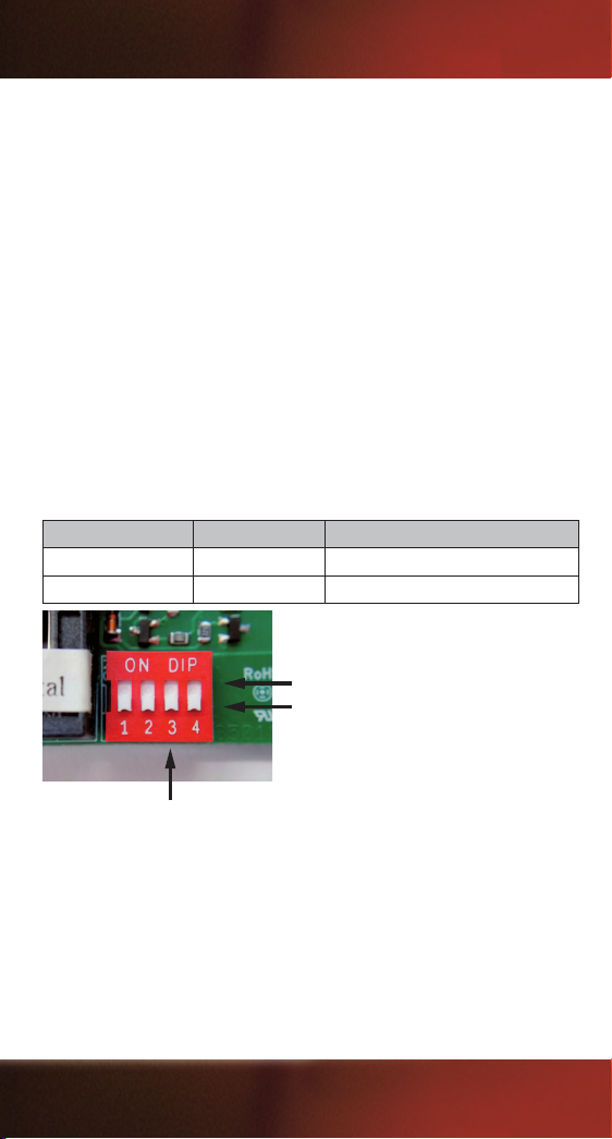
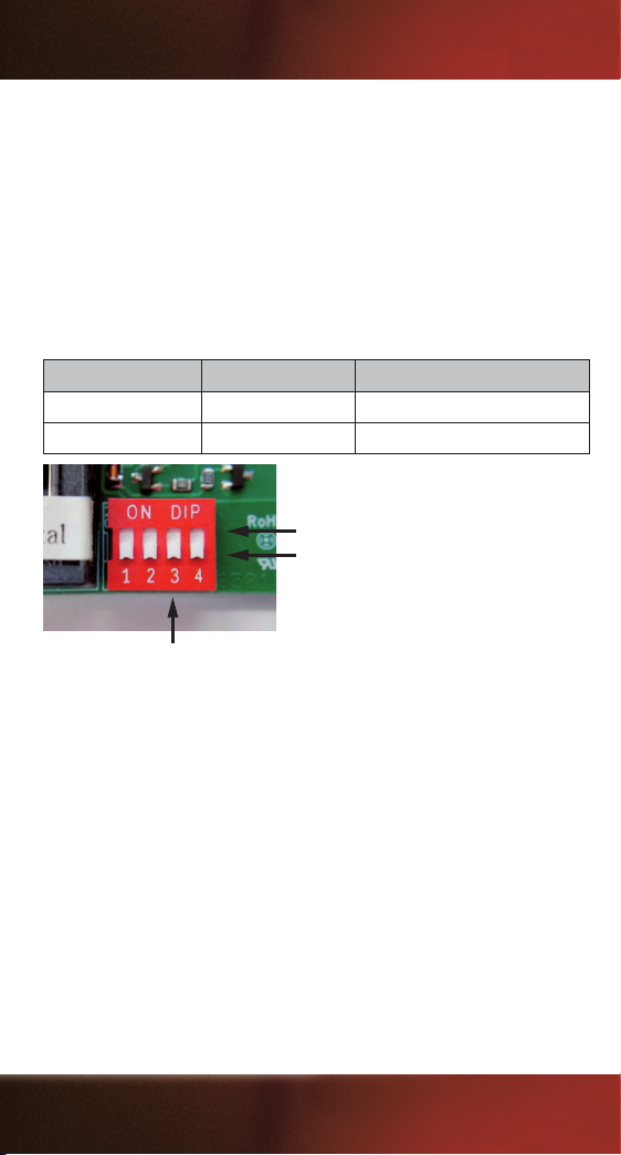
Vorne rechts bendet sich ein 4-fach Kodierschalter für die Einstellung vom Betrieb
mehrerer Navigatoren.
Die ID Vergabe erfolgt automatisch im Bereich der voreingestellten ID Gruppe. In der
Grundeinstellung (DIP 3=OFF) werden die ID 28 - 25 vergeben. Funk ID 1 entspricht
dann ID 28, Navigator ID 4 entspricht ID 25. Beim Einsatz eines zweiten Funkempfängers ist bei diesem DIP 3 auf ON zu stellen. Hier werden der Funk ID 1 - 4 die
ID 20 - 17 zugeordnet. Somit können 2 Empfänger gleichzeitig bis zu 8 Navigatoren
betreiben. Es kann auch ein 2,4 GHz Funkempfänger und ein Funkempfänger mit
433 MHz, bzw. 915 MHz-Technik (PIKO Artikelnummer: 35012 / 35022) parallel
betrieben werden. Auch hier ist die ID Gruppe unterschiedlich zu wählen. Wird nur
ein 2,4 GHz Funkempfänger mit maximal vier Navigatoren betrieben, kann dieser im
Auslieferungszustand (alle DIP-Schalter auf OFF) verwendet werden.
Die Kanaleinstellung im Empfänger muss mit der Einstellung im PIKO Navigator #35017 übereinstimmen.
Weitere Information zum Einsatz des Funkempfängers nden Sie in den Bedienungsanleitungen des PIKO Navigators (#35017), der PIKO Digitalzentrale (#35010)
und des PIKO Analog-Fahrreglers (#35002).
ID Gruppe / ID group DIP 3 ID Bereich / DIP range
A OFF 28-25
B ON 20-17
ON
OFF
Bild 3: DIP – Einstellungen
5.1 Betriebsarten
Im Navigator-Menü unter LogIn 2.4 stehen folgende Betriebsarten zu Verfügung:
• STD: Der Navigator zeigt bei Anmeldung STD (Standard) im Display
(im Normalbetrieb wird oben rechts die Navinummer und die Betriebsart angezeigt
(z.B. „Navi 1s“). Bei dieser Anmeldeform wird bei voller Verbindungsliste der älteste
Navigator aus der Liste gelöscht.
• PRI: Der Navigtor zeigt bei Anmeldung PRI (Priorität) im Display
(im Normalbetrieb wird oben rechts die Navinummer und die Betriebsart angezeigt
(z.B. „Navi 1p“). Bis zu zwei Navigatorn können unter dieser Option angemeldet
4
Page 5

werden. Diese werden dann auch bei voller Verbindungsliste nicht gelöscht. Sind
bereits zwei Navigatoren mit PRI angemeldet, meldet sich ein dritter Navigator
automatisch als STD an.
• DIR: Der Navigtor zeigt bei Anmeldung DIR (Direktfunk) im Display (im Normalbetrieb wird oben rechts die Navinummer und die Betriebsart angezeigt
(z.B. „Navi 1d“). Diese Funktion steht aktuell noch nicht zur Verfügung.
6. Zurücksetzen auf Werkseinstellungen
Zum Löschen der Verbindungsliste kann ein Werksreset durchgeführt werden. Dazu
ist das Gehäuse durch das Lösen der vier Schrauben zu öffnen.
Auf der Platine sind alle DIP-Schalter auf ON zu stellen und beim Einstecken des
Kabels ist der Anmeldetaster gedrückt zu halten. Nach einer Sekunde kann der
Empfänger wieder von der Zentrale getrennt werden. Stellen sie die Dipschalter
wieder auf die vorherige Einstellung. Nun können wieder Navigatoren, wie unter
Punkt 3 beschrieben, angemeldet werden.
Hinweise:
• Vor einer Reinigung sind alle angeschlossenen Kabel vom Funkempfänger zu trennen.
• Stellen Sie den Funkempfänger auf einer stabilen, achen und gut zugänglichen Unterlage auf.
• Befestigen Sie den Funkempfänger bei dauerhafter Installation an den dafür vorgesehenen
Punkten am Gehäuseboden. Bohren Sie auf keinen Fall zusätzliche Löcher in das Gehäuse.
• Schalten Sie die Stromversorgung ab, wenn Sie Ihre die Anlage verlassen. Lassen Sie Ihre
Anlage nie unbeaufsichtigt in Betrieb.
• Zur Schadensbehebung ist der Funkempfänger an den Hersteller oder einen bevollmächtigten
Vertreter zurückzusenden.
• Der Funkempfänger ist für Kinder unter 14 Jahren nicht geeignet. Er dient ausschließlich zur
Verwendung in Modellbahnanlagen.
• Bitte weisen Sie Ihre Kinder darauf hin, dass der Funkempfänger nur entsprechend seiner
Bestimmung eingesetzt werden darf.
• Alle Anschlussarbeiten sind grundsätzlich bei abgeschalteter Betriebsspannung durchzuführen.
• Die Stromquelle muss so abgesichert sein, dass es im Falle eines Kurzschlusses nicht zum
Kabelbrand kommen kann.
• Stellen Sie Ihren Funkempfänger, wie auch Ihre Netzgeräte, Schaltpulte usw. möglichst
wettergeschützt auf. Die Dichtungen sollen lediglich vor kurzzeitiger, leichter und senkrechter
Nässeeinwirkung schützen.
• Lassen Sie deshalb das Gerät nicht ungeschützt im Freien stehen, da die empndliche Elektronik Schaden nehmen könnte.
• Die Bedienung, Überprüfung und der Anschluss der verwendeten Geräte liegen in der Verantwortung der Aufsichtsperson.
5
Page 6

Garantieerklärung:
Über die Ihnen gegenüber Ihrem PIKO Fachhändler als Vertragspartner gesetzlich zustehenden
nationalen Gewährleistungsrechte hinaus gewährt Ihnen die PIKO Spielwaren GmbH beim Kauf
eines PIKO Produktes zusätzlich eine Herstellergarantie von 2 Jahren ab Kaufdatum zu den
nachfolgend aufgeführten Bedingungen. Damit haben Sie unabhängig vom Kaufort die Möglichkeit, auch direkt bei PIKO aufgetretene Mängel oder Störungen zu reklamieren.
Garantiebedingungen
Diese Garantie gilt für PIKO Produkte und Einzelteile, die bei einem PIKO Fachhändler weltweit
gekauft wurden. Als Kaufnachweis dient die Kaufquittung.
Inhalt der Garantie / Ausschlüsse
Die Garantie umfasst nach Wahl von PIKO die kostenlose Beseitigung eventueller Störungen
oder den kostenlosen Ersatz schadhafter Teile, die nachweislich auf Material-, Konstruktions-,
Herstellungs- oder Transportfehlern beruhen inklusive der damit verbunden Serviceleistungen.
Weitergehende Ansprüche sind ausgeschlossen.
Die Garantieansprüche erlöschen
• bei verschleißbedingten Störungen bzw. bei der üblichen Abnutzung von Verschleißteilen.
• bei Umbau von PIKO Produkten mit nicht von PIKO freigegebenen Teilen.
• wenn der Einbau bestimmter Elektronikelemente entgegen der Vorgabe von PIKO von nicht
dafür autorisierten Personen durchgeführt wurde.
• bei Verwendung in einem anderen als von PIKO bestimmten Einsatzzweck.
• wenn die in der Bedienungs-/Wartungsanleitung aufgeführten Hinweise von PIKO nicht befolgt
wurden.
Die Garantiefrist verlängert sich durch Instandsetzung oder Ersatzlieferung nicht. Die Garantieansprüche können entweder direkt beim Verkäufer oder durch Einsenden des reklamierten
Teils zusammen mit der Kaufquittung und einem Mängelbericht direkt an die Firma PIKO gestellt
werden. Die Einsendung erfolgt zu Lasten des Käufers. Unfreie Sendungen werden nicht
angenommen.
Elektrische und mechanische Maßangaben sowie Abbildungen ohne jede Gewähr.
Irrtümer vorbehalten! Daten können sich ohne Vorankündigung ändern.
6
Page 7
35018
R/C Receiver 2.4 GHz
1. Technical Specications:
• Power Supply 5...24 V DC (depending on Central Station or controller)
• Current consumption 30 mA in idle mode
• Frequency band 2,402...2,480 GHz
• Transmitting power max. 10 mW typ 1 mW 0...9.5 dBm
• Temperature range -20 ... +45°
• Dimensions 3.74“ x 2.56“ x 0.91“
This device contains:
FCC ID: WAP4110; IC: 7922A-4110
(Please see backside of documentation for Regulatory Information)
1.1 Contents:
• R/C Receiver 2.4GHz
• Bus cable Digital (6-pole) + Bus cable Analog (8-pole)
• User manual
2. Brief Description
The PIKO radio receiver transforms the radio data from the PIKO Navigator into
analog or digital signals for the PIKO analog drive controller or the PIKO digital
railway center. Its 2.4GHz-radio technology equips it to function virtually free of
distrubtions. Its reach depends on location`s conditions. Other transmitters using
the same frequency or other obstacles between transmitter and receiver (e.g. walls)
may reduce or limit radio trafc. The connection is made using one of the two bus
cables. The receiver is mounted in the housing and protected from weather inuences.
However, when using the unit outdoors it is advisable to place the protected assembly
inside a model building for instance in order to protect the sensitive electronics.
2.1 Connection:
Open the housing by removing the 4 screws in the covering and remove the
covering. Carefully remove the circuit board from the housing and place it onto
a stabile, non-slip base such as a mouse pad. Insert the required cable into the
corresponding socket with the contact surface facing upwards.
The radio receiver #35018 includes two connection cables (1 analog 8-pole for
#35002 and 1 digital 6-pole for #35010). Please only connect one of the two cables.
The operation of both operational modes (analog und digital) at the same time is not
supported.
Attention: The Analog data cable plug has 8 pins and is wider than the 6-pin
Digital data cable plug. Never insert the narrower plug into the wider socket on
the Analog Throttle. This can damage the devices. (See illustration)
7
Page 8
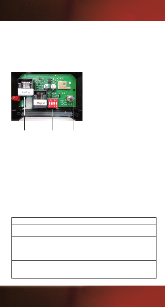
In order to disconnect the inserted cable, you must rst press the small latch lever on
(for #35002)
(for #35010)
the connector and then remove the connector from the socket. Carefully place the
circuit board back inside the housing. Close the housing and screw the cover back
on with a suitable screwdriver. Ensure that the cable is properly and that the sealing
of the radio receiver is in its proper position. Now connect the cable to the digital
railway center or the driver controller (See the corresponding Operating Instructions)
laid.
Analog-Plug
Fig. 1: Options of connection
Digital-Plug
DIP-Switch Push-Button
2.2 Mounting:
The radio receiver can be fastened with the 4 strips located on the sides.
2.3 Operation:
When the unit is switched on and idle, the LED blinks (long on, long off), thereby
indicating that there is not yet a connection to the radio remote control.
As soon as a radio remote control is recognized, the LED illuminates without
interruption.
During operation for the rst time, after a default reset, or if a new device should
to be registered, the LED blinks symmetrically fastly. The radio receiver can be
operated with up to four digital handheld controllers simultaneously.
Operating State of the STATUS LED
On (permanent) Regular operation with one or more
transmitters
Flashing (symmetric fast) Receiver searches for transmitters,
e.g. when rst switched on, after
factory reset or if a new device is to be
registered via the push-button.
Flashing (symmetric slow) Radio receiver Standby after switching
on or if no transmitter is active for a
long time.
8
Page 9
2.4 Positioning and Range:
A radio range of approximately 164 feet can be reached and even more.
The radio range depends on local conditions. Transmitters on the same frequency
like garage door openers, radio thermometers, radio headphones, radio mouse or
radio keyboards and other obstacles between sender and receiver like walls can limit
the radio range.
Set up the receiver in a way that the range is not exeeded by any portion of your
layout. The receiver should have at least a 3 feet distance from transformers, digital
central station and the tracks. Do not lay the cable parallel to the tracks. If necessary
try several positions to determine the best location for the receiver.
35018
ca. 50m
ca. 164ft
House
House
Fig. 2: Positioning and Range
3. Establish radio connection:
Please ensure to use a 2.4GHz Navigator system. The rst connection (or re-
connection after a reset) will happen usually automatically. If this is not the case,
just bring the Navigator into connection mode. You nd the required setting in the
Navigators menu. For further registrations or if the rst registration was unsuccessful,
please press the push button on the receiver for 5 seconds until the status LED is
symmetrically blinking fastly.
While blinking, you can register another navigator. Already registered radio
participants can login without registration. If this does not work, it can either be
because the maximum capacity of users is reached (more than eight transmitters
on the list) or a reset has been initiated. The systems connection list always deletes
the oldest navigator rst. Up to two navigators can be saved before deleting from
the connection list. For this, you have to select the Pri for „priority“ option in your
navigator menu (RC Cong --> LogIn 2.4).
4. ID - Identication number:
The RC Receiver is passive and does not require an ID that can be congured by
the user. When registrating a Navigator, the central station automatically identies
the receiver and allocates an ID.
9
Page 10
5. Settings:
A 4-way coding switch for the multiple - Navigator ID settings is located at the front
on the right The ID assignment takes place automatically in in the range of the preset
ID group. With the basic setting (DIP3=OFF) ID 28 – 25 are allocated. Navigator ID 1
then equals 28, ID 4 equals 25. If a second receiver is operated, the DIP switch has
to be set to DIP 3 = ON. This will allocate the IDs numbers 20 - 17 to the Navigator
IDs 1 - 4. This way, 2 Receivers can operate up to 8 Navigators. You may also
operate a 2.4 GHz Receiver and a Receiver with 433 MHz or 915 MHz technology
(#35012 / #35022) at the same time. In this case you also need to select different
ID groups. If only one 2.4 GHz RC receiver is operated with a maximum of four
navigators, it can be operated on the factory setting (all DIP switches OFF).
ID Gruppe / ID group
DIP 3 ID Bereich / DIP range
A OFF 28-25
B ON 20-17
ON
OFF
Fig. 3: DIP – settings
5.1 Operation Mode
The following operating modes are available under LogIn 2.4 (menu folder in the
2.4GHz Navigator #35017):
• STD: The Navigator shows STD (standard) in the display when logging in
(in normal operation upper right the user number and the operation mode is shown
(e.g. „Navi 1s). With this mode, the oldest Navigator is deleted from the list when
the connection list is full.
• PRI: The Navigator shows PRI (priority) in the display during login (in normal
operation upper right the user number and the operation mode is shown
(e.g. „Navi 1p). Up to two Navigators can be logged in under this option. They will
not be deleted even if the connection list is full. If two Navigators are already logged
in with PRI, a third Navigator automatically logs in as STD.
• DIR: The Navigator shows DIR (direct control) in the display (in normal operation
upper right the user number and the operation mode is shown (e.g. „Navi 1d). This
function is not yet available.
10
Page 11

6. Reset to factory defaults
In order to fully delete the connection list you can initiate a factory reset. The housing
has to be opened by loosening the four screws.
All DIP switches on the circuit board have to be set to ON and the push button has
to be kept pressed while connecting the cable. After one second the RC Receiver
can be separated from the central station. Now reset the DIP switches to their former
setting. You can then go ahead and register navigators as described above.
Important Instructions:
• All cables must be disconnected from the controller prior to cleaning it.
• Place the radio receiver on a stabile, at, easily accessible base.
•
For a permanent installation, afx the radio receiver using the pre-drilled holes on the base
of the housing. Under no circumstances should you drill additional holes in the housing.
• Shut off the power when you leave your train system alone. Never leave your train
system in operation unsupervised.
• For repairs, the radio receiver must either be sent to the manufacturer or brought to one
of the manufacturer’s authorized representatives.
• The radio receiver is not suitable for children under the age of 14. It serves only for use
inmodel train systems.
• Please instruct your children that the radio receiver may only be used in accordance with
its intended purpose.
•
All connection work is fundamentally to be conducted with the electrical supply switched off.
• The source of electricity must have a fuse sufcient for preventing a cable re in the
event of a short circuit.
• Please maintain your radio receiver, its power supply units, control panels, etc., in an
environment that is protected as well as possible from weather inuences. The sealings
are only designed to provide protection from the mild, short-term incursion of moisture
from above.
• Therefore do not leave the device unprotected outdoors, since otherwise the sensitive
electronics could be damaged.
•
The supervising person is responsible for the operation, inspection and connecting of the devices.
Warranty
Upon purchase of a PIKO product the rm of PIKO Spielwaren GmbH gives you
a Manufacturer‘s warranty of 24 months from the date of purchase in addition to and
beyond the warranty performance rights available to you legally in your country vis-à-vis
your authorized PIKO dealer as the contractual selling party. This warranty is given with
the following conditions listed below. Regardless of where you purchased the product, you
thereby have the possibility of submitting for warranty claim defects or aws occurring with
the product to the rm of PIKO as the manufacturer of the product.
Warranty Conditions:
This warranty applies to PIKO products and spare parts that have been purchased from any
of our worldwide authorized PIKO dealers. The sales receipt will serve as proof of purchase.
Warranty Coverage / Exclusions
This warranty includes, at the discretion of the manufacturer, correction free of charge of
any defects or the replacement free of charge of damaged parts that are due to defects
11
Page 12

in design, production, material or transportation inclusive of the service performance
connected with these defects. Any further claims are excluded.
Warranty claims become null and void
• when the defects are caused by wear and tear or by normal wear of parts subject to wear
and tear.
• when PIKO products have been converted with parts not authorized by the manufacturer.
• when the installation of specic electronic elements has been carried out by parties
notauthorized by the manufacturer for such an installation.
• when the product has been used in a manner not intended by the manufacturer.
• when the information in the operating instructions provided by the manufacturer has not
been followed.
Repair or replacement of a product does not extend its warranty period. Warranty claims
can be submitted directly to the seller, or the part to be submitted for warranty can be sent
directly to the rm of PIKO along with sales receipt and a summery of the problem(s) with
the product. Shipments have to be prepaid.
Given electrical and mechanical data as well as illustrations are without guarantee.
Mistakes of any kind are reserved. Given data is subject to change without notice.
REGULATORY INFORMATION:
1. FCC Information (USA):
This device contains FCC ID: WAP4110.
The device CYBLE-224110-00 complies with Part 15 of the FCC Rules. The device meets the
requirements for the modular transmitter approval as detailed in FCC public Notice DA00-1407.
Transmitter Operation is subject to the following two conditions: (1) This device may not cause
harmful interference, and (2) This device must accept any interference received, including
interference that may cause undesired operation.
2. ISED Information (Canada):
This device contains IC: 7922A-4110.
The device CYBLE-224110-00 including the built-in chip antenna complies with Canada RSSGEN Rules. The device meets the requirements for modular transmitter approval as detailed in
RSS-GEN. Operation is subject to the following two conditions: (1) This device may not cause
harmful interference, and (2) This device must accept any interference received, including
interference that may cause undesired operation.
L‘appareil CYBLE-224110-00, y compris l‘antenne intégrée, est conforme aux Règles RSS-GEN
de Canada. L‘appareil répond aux exigences d‘approbation de l‘émetteur modulaire tel que décrit
dans RSS-GEN. L‘opération est soumise aux deux conditions suivantes: (1) Cet appareil ne doit
pas causer d‘interférences nuisibles, et (2) Cet appareil doit accepter toute interférence
reçue, y compris les interférences pouvant entraîner un fonctionnement indésirable.
3. MIC Japan
CYBLE-224110-00 is certied as a module with type certication number 203-JN0568.
4. KC Korea
CYBLE-224110-00 is certied for use in Korea with certicate number MSIP-CRM-Cyp-4110.
35018-90-7000 © 2019, PIKO Spielwaren GmbH
PIKO Spielwaren GmbH · Lutherstr. 30 · 96515 Sonneberg, GERMANY
 Loading...