

Page 1
MISSION
In odu ion
Congratulations on your purchase of the Pigtronix
Dual Expression pedal. This product is designed to
be intuitive to setup and operate, and to provide
many years of trouble free service. However, we
recommend that you take a few moments to read
through this User Guide in order to get the best
possible experience with your new pedal.
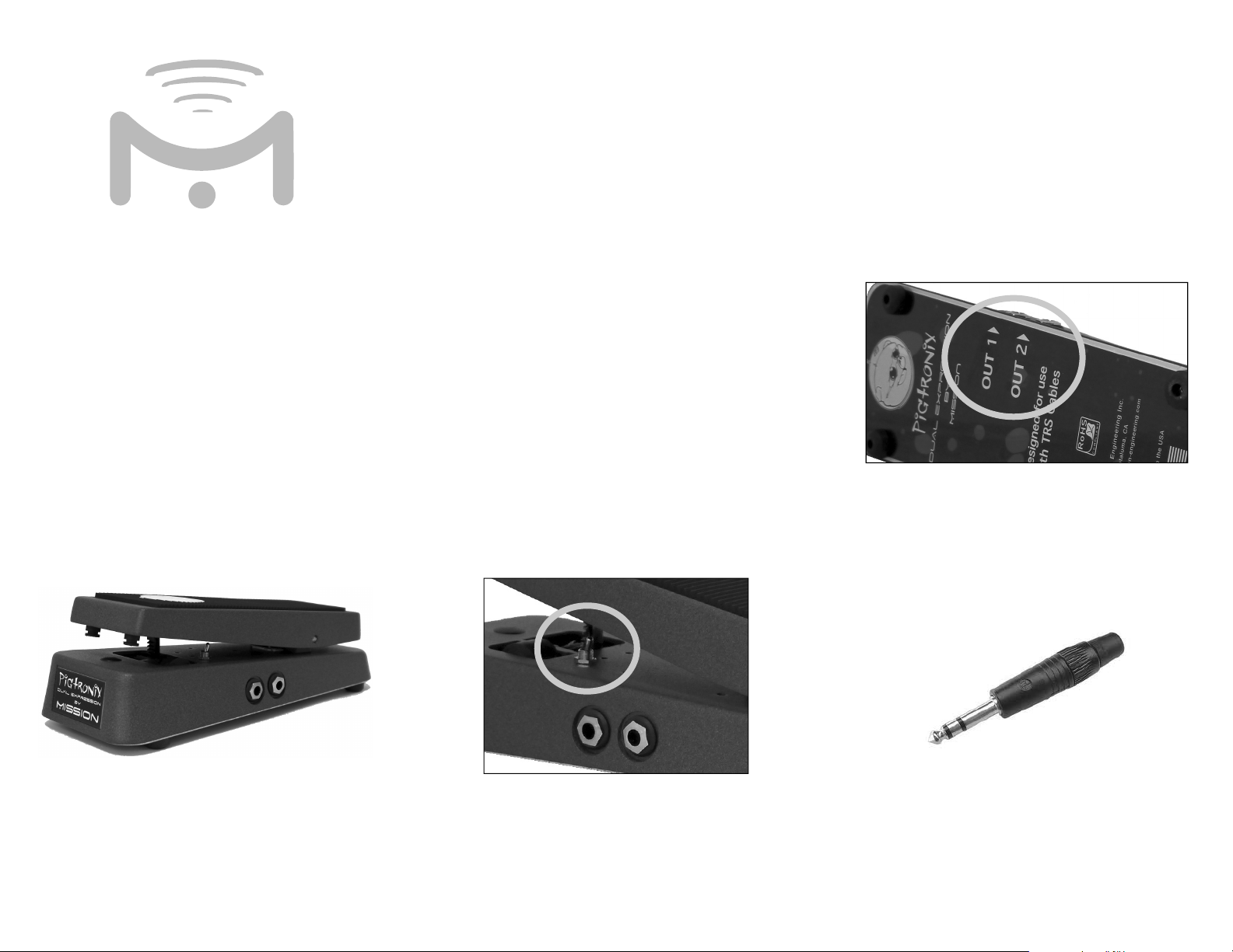
ConnE ions
The Pigtronix Dual Expression pedal uses two ¼”
TRS phone plug outputs marked OUT1 and OUT2
on the underside of the pedal. Connect the outputs
to expression pedal inputs on your devices using
¼” TRS-TRS instrument cables such as the Mission
MCTRS3A cable. If you only intend to use the pedal
with one device, you can connect either output and
leave the other unused.
ENGINE ING
Pigtronix
DuAl
Expr sion
P Al
f tur
The Pigtronix Dual Expression pedal features
two TRS expression outputs that are controlled
simultaneously from the one pedal allowing control
of two effects at the same time. A direction reversal
toggle permits one output to operate in reverse so
that two separate effects can be varied in opposite
directions for advanced expression control. The
Pigtronix Dual Expression pedal uses a full range
linear potentiometer and is designed to work with
effects pedals from many different manufacturers,
not just Pigtronix.
TRS stands for Tip, Ring, Sleeve and is a threeconductor cable. It is sometimes also called a stereo
or balanced cable. The pedal requires the use of the
correct cable with a TRS connector at both ends. A
mono TS cable such as a regular guitar cable, and
insert cables that have both TS and TRS plugs, will
not work in most cases.
Figure 1.
U r
Guide
pow
This expression pedal is a passive device, and
requires no internal battery or external power.
Figure 1. A TRS connector with the three conductors
separated by the black insulation bands. The pointed
front of the connector is the tip, the middle band is
the ring, and the large conductor at the rear nearest
the plug body is the sleeve.
Page 2

U
Some devices will require proper configuration
before use with an expression pedal. Be sure to
read the User Manual for your device, and setup and
calibrate the expression pedal in accordance with the
instructions if necessary. Most manufacturers have
copies of their User Manuals available online.
Moving the rocker on the expression pedal will
change the parameters between minimum at heel
down and maximum at toe down. If used, both
outputs will vary simultaneously.
The direction of OUT1 can be reversed using the
small toggle switch at the front of the pedal. The
factory default is normal operation with the toggle
switched towards the rear of the pedal. To reverse
the direction of OUT1, switch the toggle towards
the front of the pedal. The sweep on OUT1 will
now be reversed; with maximum at heel down and
minimum at toe down. OUT 2 cannot be reversed.
Adju mEnts
The tension of the rocker can be adjusted using the
tension adjustment screw on the rear of the pedal
between the rocker and the base. Use the hex key
provided to tighten the adjustment screw until the
pedal remains in place. It maybe necessary to adjust
this screw every once in a while to compensate for
use and environmental conditions such as very hot or
cold weather, when the pedal has been stored for a
long period, or after shipping. Replacement hex keys
are available from Mission Engineering.
Sa ty
In ru ions
Read, Keep & Follow these instructions
Heed all warnings
Clean only with dry cloth
Do not use this apparatus near water
Do not expose the apparatus to dripping or
splashing and ensure that no objects filled with
liquids, shall be placed on the apparatus
WARNING: To reduce the risk of fire or electric
shock do not expose this apparatus to rain or
moisture
Unplug this apparatus during lightning storms or
when unused for long periods of time
Do not block any ventilation openings. Install in
accordance with the manufacturer’s instructions
Do not install near any heat sources such
as radiators, heat registers, stoves, or other
apparatus (including amplifiers) that produce
heat
Only use attachments/accessories specified by
the manufacturer
Prolonged listening at high volume levels may
cause irreparable hearing loss and/or damage.
Always be sure to practice “safe listening.”
Refer all servicing to qualified service personnel.
Service is required when the apparatus has been
damaged in any way, such as:
- power-supply cord or plug is damaged
- liquid has been spilled or objects have fallen
into the apparatus
- the unit has been exposed to rain or moisture.
- the unit is dropped or the enclosure is
damaged
- the unit does not operate normally or changes
in performance in a significant way
ecifi tions
Electrical Specifications
Potentiometer
Internal resistance – 25K Ohm
Taper – Linear
Polarity – Tip to wiper
Function – Voltage Divider
Usage Rating - > 1M cycles
Dimensions
Base length at longest point - 9.9”
Base width at widest point - 4.0”
Height at highest point including feet - 3.25”
Pedal length - 8.7”
Pedal width at widest point - 3.0”
Pedal width at narrowest point - 2.3”
Weight - 3.5lbs
Mission Engin ring Inc.
www.missionengineering.com
info@mission-engineering.com
©
Mission Engineering Inc. 2013. Trademarks, registered trademarks,
product names, logos and other materials are the property of their
respective owners.
 Loading...