

Page 1

PIE 830
Process Calibrator
Loop Diagnostics • Transmitter Supply
mA • V • pH •TC • Ω • RTD • Freq • Pressure
Operating Instructions
PIE 830
Process Calibrator
Loop Diagnostics • Transmitter Supply
mA • V • pH •TC • Ω • RTD • Freq • Pressure
Operating Instructions
Find Quality Products Online at: [email protected]
www.GlobalTestSupply.com
Page 2

Contents
General Operations
Accessories ............................................................................. 3
Carrying Case, Boot & Changing Batteries ............................4
Storing EZ-CHECK Outputs & Connections ........................... 5
Basic Operation
Switches & Knobs ............................................................... 6, 7
MAIN Menus - Functions, Units & Ranges .........................8, 9
FEATURE Menu - Stepping & Ramping / Auto Off ............... 10
FEATURE Menu - Stepping & Ramping / Backlight ............. 11
Functions and Hookup Diagrams
2-Wire Transmitter Calibration
Simulate sensor while powering 2-Wire Transmitters ...... 12, 13
Universal Isolated Transmitter
Use the 830 to replace a 2-Wire Transmitter ................... 14-17
Milliamp
Simulate 2 Wire Transmitters ........................................... 18, 19
Source mA, Read mA .....................................................20, 21
Power/Measure Transmitters ................................................. 22
Using Ground Leak Detection ......................................... 23, 24
Voltage & Millivolt
Source V & mV; Read V & mV ........................................ 25, 26
pH
Source pH ........................................................................27, 28
Thermocouple
Source T/C & Read T/C Sensors .................................... 29, 30
Resistance
Source Resistance, Read Resistance & Continuity ........ 31, 32
RTD
Source RTD & Read RTD Sensors.................................33, 34
Frequency
Source KHz, Hz & CPM; Read KHz, Hz & CPM ............35, 36
Pressure
Read Pressure ...................................................................... 37
Pressure Accessories ............................................................ 38
Pressure Module Ranges & Specifications ........................... 39
Specifications
General ............................................................................40-44
Thermocouple Ranges & Accuracies...............................45-47
RTD Ranges & Accuracies ................................................... 48
Warranty
Warranty & Additional Information ........................................ 49
Find Quality Products Online at: [email protected]
www.GlobalTestSupply.com
Page 3

General Information
Get more tools in a smaller calibrator
Carry eight single function calibrators
plus
a milliamp calibrator with loop supply
plus
a loop troubleshooter in the palm of your hand!
Milliamp • Voltage • Frequency • pH • Ohms
Thermocouples • RTDs • Pressure
Loop Diagnostics • Transmitter Supply
Detect ‘hidden’ loop problems
Quickly diagnose troublesome ground faults & current leakage with patented Loop Diagnostic technology. These prob-
1
2
Patented by PIE!
3
lems are undetectable with other instruments!
Check all loop parameters at once with LoopScope™
Simultaneously displays current, voltage and resistance
to let you know the condition of a live loop. Finds problems with power supplies & loops with too many loads.
Automatically detect 2, 3, or 4 wire RTDs
Trouble shoot sensor connections and find broken wires with
patented technology. LCD indicates which of the four wires
are connected to an RTD sensor.
Swap out faulty transmitters to diagnose control issues
Easily setup the 830 as a universal isolated transmitter for
Thermocouple, RTD, frequency, millivolt, resistance or pres-
4
transmitter was faulty. Turn on the LoopScope to
simultaneously see the loop current, loop voltage and loop
loads for troubleshooting.
5
Find Quality Products Online at: [email protected]
sure. If the loop is back under control you know the
Troubleshoot wiring problems without a multimeter
Built in continuity checker with ‘beeper’ quickly finds broken
wires or shorts in instrumentation wiring. Also handy for
checking operation of relays and controller outputs.
Page 1
www.GlobalTestSupply.com
Page 4

The PIE Model 830 is more than a multifunction
calibrator. It is also a loop detective that is able to
diagnose common problems that other test
equipment just can’t find. Have a flooded junction
box or unknown ground faults? Our Loop Diagnostic
technology will detect it. Or use the LoopScope to
see at a glance all the parameters - milliamps,
voltage and resistance - in the loop.
Stop throwing away perfectly good transmitters
only to find the problem is somewhere else in the
loop. Setup the PIE Model 830 as an isolated
universal transmitter and turn on the Loop
Diagnostics. The display will tell you EXACTLY the
sensor input, the current output and if there is any
uncontrolled current in the loop due to a ground
fault, corrosion bridge or moisture. If the control
system sees no problem when the 830 is acting as
a transmitter THEN you can replace the faulty
transmitter. With RTDs the 830 automatically detects
which of the 2, 3 or 4 wires are connected and
unbroken quickly alerting you to a sensor problem.
Diagnostic features are covered by
US Patent
#7,248,058.
Become a troubleshooting technician with
Patented Diagnostic Technology - Available only
with PIE Calibrators!
Page 2
Find Quality Products Online at: [email protected]
www.GlobalTestSupply.com
Page 5

Accessories
INCLUDED:
Four “AA” Alkaline batteries, Certificate of Calibration
Evolution Hands Free Carrying Case Part No. 020-0211
Blue Rubber Boot Part No. 020-0213
Test Leads - one pair with Part No. 020-0207
banana plug & alligator clips
Evolution RTD Wire Kit Part No. 020-0208
2 Red & 2 Black Leads with
Banana Plugs & Spade Lugs
OPTIONAL:
Ni-MH 1 Hour Charger with 4 Ni-MH AA Part No. 020-0103
Batteries (100-120 V AC input for North America Only)
T/C Wire Kit 1* for Types J, K, T & E Part No. 020-0202
T/C Wire Kit 2* for Types B, R/S & N Part No. 020-0203
*Three feet (1 meter) of T/C extension wire, stripped on one
end with a miniature T/C male connector on the other end.
Page 3
Find Quality Products Online at: [email protected]
www.GlobalTestSupply.com
Page 6
Operating Instructions
FIELD & BENCH USE
PIE 830 comes with a carrying case designed for hands-free
operation and a rubber boot with a built-in tilt stand. The PIE 830
is held in the case by elastic straps for use with the carrying
case open. The tilt stand is easily raised by pulling the stand until
it locks into place.
CHANGING BATTERIES
Low battery is indicated by a battery symbol on the display.
Approximately one to four hours of typical operation remain before
the PIE 830 will automatically turn off. To change the batteries
remove the rubber boot and remove the battery door from the
back of the unit by sliding the door downward. This allows access
to the battery compartment. Replace with four (4) “AA” 1.5V
batteries being careful to check the polarity. Replace the battery
door and replace the boot. All stored configuration options (T/C
Type, EZ-CHECK Memories, etc.) are reset to factory settings
when the batteries are removed.
Note: Alkaline batteries are supplied and recommended for
typical battery life and performance. Optional rechargeable
batteries (charged externally) are available.
Page 4
Find Quality Products Online at: [email protected]
www.GlobalTestSupply.com
Page 7
Operating Instructions
STORING HI and LO EZ-CHECK Source Outputs
Speed up your calibration by storing Span & Zero output setting
for instant recall with the EZ-CHECK switch.
1) Store your high (SPAN) output temperature by moving the
EZ-CHECK switch to the HI position and turning the EZ-Dial
knob until the desired output value is on the display. Press
and hold the EZ-Dial knob until STORED appears to store
the value. Release the EZ-Dial knob.
2) Store your low (ZERO) output value by moving the EZ-CHECK
switch to the LO position and turning the EZ-Dial knob until
the desired output value is on the display. Press and hold the
EZ-Dial knob until STORED appears to store the value.
Release the EZ-Dial knob.
3) Instantly output your SPAN and ZERO output settings by
moving the EZ-CHECK switch between HI and LO. You may
also select any third output setting (such as mid-range) using
the SET position on the EZ-CHECK switch.
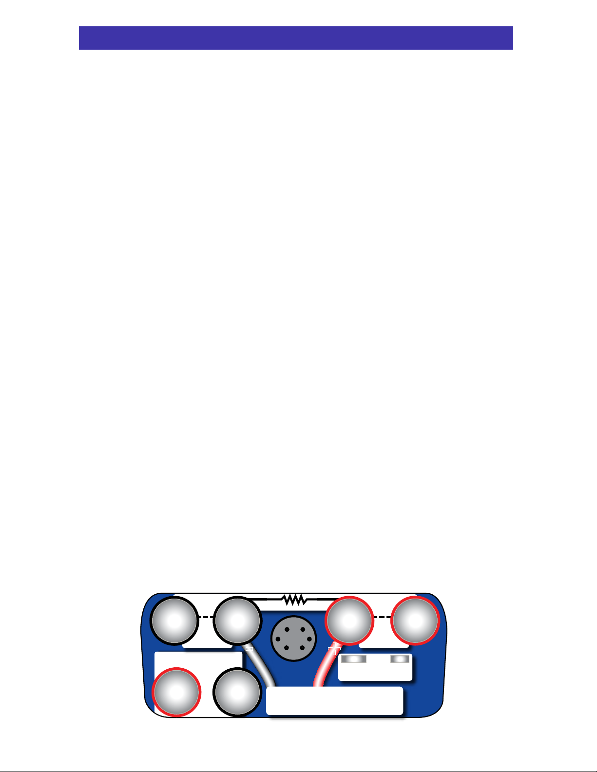
Connections
PIE 830 has banana jacks compatible with unshielded or
retractable banana plugs. Included with your calibrator are a pair
of test leads with alligator clips for mA, V, pH & Hz connections.
Four test leads with spade lugs are also included for 2, 3 and 4
Wire RTD connections. Thermocouple connections are made
through a miniature thermocouple socket.
23
1
4
Ω
RTD
All mA∙ Read V
-
+
65
-
Source & Read Hz∙ mV
+
Source V∙ pH
Ω
RTD
-
T/C
Page 5
Find Quality Products Online at: [email protected]
www.GlobalTestSupply.com
Page 8
Operating Instructions
Basic Operation
PWRM
+
-
5 6
18.300 mA
830.0 °C
TYPE K
SOURCE
MAX
HI
READ
SET
MIN
LO
READ
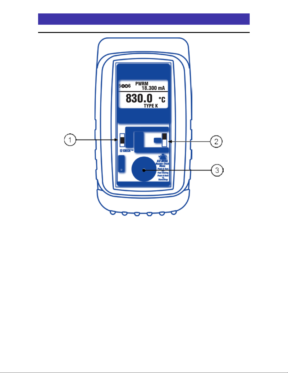
q EZ-CHECK™ SWITCH
SOURCE: Instantly output two preset settings by moving the
EZ-CHECK™ switch to the “LO” position or “HI” position.
three point checks select the “SET” position. The PIE 830 will
remember the last “SET” value, even with the power off.
These values can easily be changed to suit the calibration requirements.
The values stored in the HI and LO positions are also used for Auto
Stepping.
READ: Slide the switch to the SET position. The PIE 830 will display
the current reading from the sensor or device being measured. Slide
the switch to MAX and the highest value measured since turn-on or
reset will be displayed; slide the switch to MIN and the lowest value
measured since turn-on or reset will be displayed.
Page 6
For fast
Find Quality Products Online at: [email protected]
www.GlobalTestSupply.com
Page 9
Operating Instructions
Basic Operation
w SOURCE/OFF/READ Switch
Select “SOURCE” to output mA, V, pH, T/C, Ω, RTD or frequency.
Select “READ” to read mA, V, T/C, Ω, RTD, pressure or frequency.
Select “OFF” to turn off the 830.
e EZ-DIAL™ KNOB
SOURCE: Turn the knob to adjust the output level. Turn clockwise to
increase the output, counter clockwise to decrease the output in one
least significant digit step at a time. Push down and turn the
EZ-DIAL knob for faster dialing.
Press and hold the knob for two seconds to store desired
EZ-Check™ HI/LO points in SOURCE mode. Continue to press and
hold the knob for two more seconds to start the automatic ramping.
READ: Press and hold to transfer the current temperature into
the EZ-Check™ MIN/MAX points. This clears the MIN/MAX
readings which will update as the input value changes.
SELECTING FUNCTIONS
The EZ-DIAL knob is used to setup the PIE 830 to match the
instrument to be calibrated or signal to be measured. Each time
you turn on the PIE 830 the LCD displays the following screen
for about 1 second followed by operating in the function used the
last time it was operated.
PIE 830
DOUBLE CLICK
EZ-DIAL KNOB
FOR CONFIGURATION
Double Click the EZ-DIAL knob to change the function of the
calibrator and to select ranges, units and other user settings.
Each function (mA, V, T/C, Ohms, RTD, Frequency) has up to
four pages of menus. The first menu page has settings for the
function and the last menu page has settings for STEPPING,
AUTO OFF and BACKLIGHT. Settings are remembered even
with the power off but are reset when the batteries are changed.
Page 7
Find Quality Products Online at: [email protected]
www.GlobalTestSupply.com
Page 10
Operating Instructions
Double Click Menus - MAIN Page
Double click the EZ-DIAL knob to access the Double Click
Menus. Shown are the MAIN menus for each function. Turn the
knob to scroll thru the menus and press the knob to select.
Available choices are shown in grey.
Source mA & Simulate 2 Wire Transmitters
MAIN
> EXIT
FUNCTION mA
MODE SOURCE 2W SIM
UNITS mA %
HART 250Ω ON OFF
Read mA, Power/Measure Transmitters
& Leak Detect
> EXIT
FUNCTION mA
MODE READ PWR MEAS
UNITS mA %
HART 250Ω ON OFF
Source V & mV
>EXIT
FUNCTION V
RANGE 10V 100mV 1V
>EXIT
FUNCTION V
RANGE 10V 1V 60V 100mV
Read V & mV
Source pH
> EXIT
FUNCTION pH
Source & Read Frequency
> EXIT
FUNCTION FREQ
RANGE 20KHZ 10000HZ 1000HZ 2000CPM
Page 8
Find Quality Products Online at: [email protected]
www.GlobalTestSupply.com
Page 11
Operating Instructions
Double Click Menus - MAIN Page
Source & Read Thermocouples
> EXIT
FUNCTION T/C
UNITS °C °F
T/C TYPE J K E T R S B N L U G C D P
COLD JUNC ON OFF
Source RTD
> EXIT
FUNCTION RTD
UNITS °C °F
RTD Pt 100 a=3850 [*RTD Types - See Read RTD]
Read RTD
> EXIT
FUNCTION RTD
UNITS °C °F
RTD Pt 100 a=3850,
Pt 1000 a=3850; Cu 10 a=4274, Cu 50 a=4280
Ni 120 a=6720, Ni 110 a=5801
Source Ohms
>EXIT
FUNCTION OHMS
RANGE 400Ω 4000Ω
a=3902, a=3916, a=3926
Read Ohms
>EXIT
FUNCTION OHMS
RANGE 400Ω 4000Ω CONT
Read Pressure
>EXIT
FUNCTION PRESSURE
UNITS psi inH2O* ftH2O* mmH2O* cmH2O* mH2O* inHg mHg
cmHg mmHg torr kg/cm2 kg/m2 hPa kPa MPa bar mbar atm oz/in2
2
lb/ft
*Engineering unit available at 4°C, 20°C and 60°F.
Page 9
Find Quality Products Online at: [email protected]
www.GlobalTestSupply.com
Page 12

Operating Instructions
Double Click Menu - FEATURES
To change the Automatic Stepping settings
Double click the e DIAL KNOB at any time the unit is on and
the following typical display (will be different for each FUNCTION)
will appear for 15 seconds:
MAIN
> EXIT (1/2)
FUNCTION mA
MODE SOURCE
UNITS mA
HART 250Ω ON
Turn the
menu page so the word FEATURES appears at the top of the
menu.
Turn the e DIAL KNOB to move through the menu. Press the e
DIAL KNOB to toggle between OFF and ON or to change the
STEPS/RAMP and the STEP/RAMP TIME settings. These
settings are remembered even with the power off.
e DIAL KNOB to move to the second, third or fourth
> EXIT (2/2)
AUTO OFF ON
BACKLIGHT ON
STEPS/RAMP 3
STEP/RAMP TIME 5
FEATURES
EXIT MENU - exits this menu immediately and saves any
changes. Menu will automatically exit after 15 seconds of
inactivity.
AUTO OFF - If AUTO OFF is ON, the unit will turn off after 30
minutes of inactivity to save battery life. If AUTO OFF is OFF the
unit will stay on until the POWER SWITCH is moved to the off
position.
Page 10
Find Quality Products Online at: [email protected]
www.GlobalTestSupply.com
Page 13

Operating Instructions
Double Click Menu - FEATURES
STEPS/RAMP - pressing the knob will cycle through 2, 3, 5, 11
and RAMP. The endpoints of the steps or ramp are based on the
values stored in the HI and LO EZ-CHECK outputs.
2 steps will automatically switch between the values stored in
the HI & LO EZ-CHECK (0 & 100%).
3 steps between the HI, Midpoint and LO EZ-CHECK (0, 50
& 100%).
5 steps between the HI and LO EZ-CHECK in 25%
increments (0, 25, 50, 75 & 100%).
11 steps between the HI and LO EZ-CHECK in 10%
increments (0, 10, 20...80, 90 &100%).
RAMP continuously ramps up and down between the HI and
LO EZ-CHECK outputs.
STEP/RAMP TIME - pressing the knob will cycle through 5, 6, 7,
8, 9, 10, 15, 20, 25, 30 and 60 seconds.
To start the Automatic Stepping
Start automatic stepping or ramping by placing the EZ-CHECK
Switch into the HI or LO position then press and hold the e
DIAL KNOB for 6 seconds (the word STORE will appear on the
display after 3 seconds and continue to press the EZ-DIAL
KNOB) until the word STEPPING appears on the display. The
word STEPPING will appear on the display anytime the selected
automatic function is running. Stop the stepping by again
pressing and holding the
e DIAL KNOB for 3 seconds.
BACKLIGHT - If BACKLIGHT is ON the backlight will light all the
time the unit is powered up. For maximum battery life turn the
backlight off when using the calibrator in areas with enough
ambient light to read the display.
Page 11
Find Quality Products Online at: [email protected]
www.GlobalTestSupply.com
Page 14

Operating Instructions
Calibrate a 2-Wire Transmitter by sourcing the input while
monitoring the output.
Works with SOURCE pH, T/C, DC V, OHMS, RTD, FREQ and
READ PRESSURE.
Move the power switch
DIAL KNOB and the MAIN menu for the function in use will
appear for 15 seconds:
MAIN
> EXIT
FUNCTION T/C
UNITS °C
T/C TYPE K
COLD JUNC ON
Turn the
page so the word mA DISPLAY appears at the top of the
menu.
> EXIT
e DIAL KNOB to move to the second (or third) menu
mA DISPLAY
w to READ and Double click the e
MODE OFF READ PWRM READ% PWRM%
HART 250Ω OFF ON
LEAK DETECT OFF ON
Turn the e DIAL KNOB to move through the menu. Press the e
DIAL KNOB to toggle between OFF and ON or to change the
MODE setting.
HART 250Ω - turn on the 250Ω resistor if you are powering up
a HART transmitter. This provides the loop load required for
HART communication.
EXIT MENU - exits this menu immediately and saves any
changes. Menu will automatically exit after 15 seconds of
inactivity.
Page 12
Find Quality Products Online at: [email protected]
www.GlobalTestSupply.com
Page 15
Operating Instructions
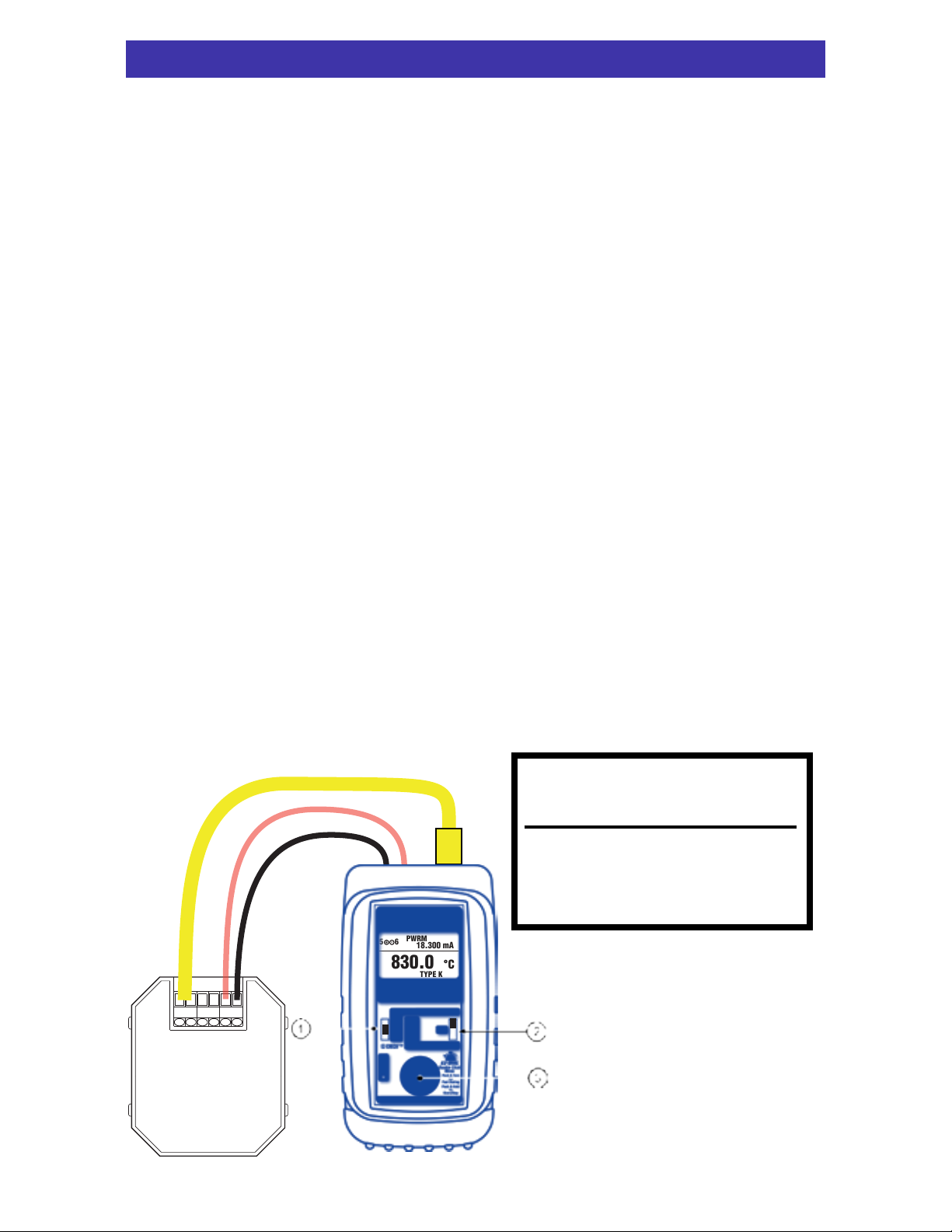
MODE - pressing the knob will cycle through READ, PWRM,
READ% ,PWRM% and OFF.
READ turns on the mA display and indicates current passing
through the loop proportional to the input of the transmitter
which is controlled by the output of the 830. Choose READ%
if your would like the mA display in percent of 4-20 milliamps.
PWRM is POWER MEASURE which uses the internal loop
supply of the 830 to power up the transmitter while indicating
the current passing through the loop proportional to the input
of transmitter which is controlled by the output of the 830.
Choose PWRM% if your would like the mA display in percent
of 4-20 milliamps.
If PWRM or PWRM% is selected an additional menu
selection of LEAK DETECT will appear. When LEAK
DETECT is turned on the 830 will display LEAK on the
display if there is more than 0.015 mA of uncontrolled current
in the loop. This may be due to a faulty transmitter, corrosion
causing a bridge to ground or moisture present at some
connection point. When LEAK DETECT tests a loop with
leakage the loop mA signal will be affected.
Thermocouple Wire
PWRM LEAK
18.300 mA
830.0 °c
TYPE K
PWRM
+
-
5 6
18.300 mA
830.0 °C
TYPE K
(Enlarged Display)
+ IN - REF +OUT-
Typical
2-Wire
Transmitter
HI
SET
LO
SOURCE
MAX
READ
MIN
READ
Page 13
Find Quality Products Online at: [email protected]
www.GlobalTestSupply.com
Page 16

Universal Isolated Transmitter
Swap out a transmitter to diagnose control issues.
The 830 acts as an isolated universal T/C, mV, OHMS, RTD,
FREQ and PRESSURE transmitter. Choose this function to
temporarily replace a transmitter when you suspect the
transmitter is faulty or to diagnose the parameters of the loop.
Move the power switch
DIAL KNOB and the MAIN menu for the function in use will
appear. Turn the
and press the e KNOB until the desired FUNCTION appears.
Turn the e DIAL KNOB to move through the menu. Press the e
DIAL KNOB to toggle the units, range, T/C Type or RTD curve.
> EXIT
FUNCTION T/C
UNITS °C
T/C TYPE K
COLD JUNC ON
MAIN
e DIAL KNOB until the pointer is at FUNCTION
MAIN
w to READ and Double click the e
MAIN
> EXIT
FUNCTION RTD
UNITS °C
RTD Pt 100 a=3850
MAIN
>EXIT
FUNCTION V
RANGE 100mV
MAIN
> EXIT
FUNCTION FREQ
RANGE 20KHZ
Turn the e DIAL KNOB to move to the second (or third) menu
page so the word XXX XMTR appears at the top of the menu.
Turn the e DIAL KNOB to move through the menu. Press the e
DIAL KNOB to toggle between DOWN and UP, OFF and ON, or
to change the MODE setting.
>EXIT
FUNCTION OHMS
RANGE 400Ω
MAIN
>EXIT
FUNCTION PRESSURE
UNITS psi
Page 14
Find Quality Products Online at: [email protected]
www.GlobalTestSupply.com
Page 17

XXX XMTR
> EXIT
MODE OFF LINEAR NONLINEAR SQ ROOT
BURNOUT DOWN UP
LOOPSCOPE OFF ON
MODE - pressing the knob will cycle through OFF, LINEAR,
NONLINEAR. When setup to read pressure SQ ROOT replaces
NONLINEAR.
LINEAR turns on the mA display and regulates the loop
current linear with the input signal. For thermocouples &
RTDs this is linear relative to the temperature between zero
and span of the sensor input. This mimics the operation of a
digital temperature transmitter or other linearizing transmitters.
NONLINEAR (applies only to thermocouples and RTDs)
turns on the mA display and regulates the loop current linear
with base units (millivolts or ohms) of zero and span of the
sensor input. This mimics the operation of an analog
temperature transmitter without linearizing.
SQ ROOT turns on the mA display and regulates the loop
current with square root extraction of zero and span of the
pressure module input. This mimics the operation of a
differential pressure transmitter setup for square root extraction.
BURNOUT selects the failure mode of the calibrator when the
input signal is lost or beyond the input scale. Down sets the output
to 1.0 mA and UP to 21.5 mA when sensor failure is detected.
LOOPSCOPE turns on the Loop Diagnostic display which
simultaneously indicates the current, voltage and resistance
of the loop. When enabled the LOOPSCOPE also indicates
errors by flashing the LED and writing diagnostic messages
on the display. Messages include LOW LOOP VOLT, HIGH
LOOP VOLT and HIGH LOOP IMPED. With LOOPSCOPE on
the 830 occasionally performs a test on the loop. During this
short test the loop mA signal will be affected.
Page 15
Find Quality Products Online at: [email protected]
www.GlobalTestSupply.com
Page 18
Setting up the 830 as a transmitter
Configure your 830 to the same Span (URV) and Zero (LRV) by
storing Span & Zero setting with the q EZ-CHECK switch.
1) Store your SPAN input by moving the
to the MAX position and turning the e EZ-Dial knob until the
desired output value is on the display. Press and hold the
EZ-Dial knob until STORED appears to store the value.
Release the EZ-Dial knob.
2) Store your ZERO input by moving the EZ-CHECK switch to
the MIN position and turning the EZ-Dial knob until the
desired output value is on the display. Press and hold the
EZ-Dial knob until STORED appears to store the value.
Release the EZ-Dial knob.
3) Move the EZ-CHECK switch to the READ position. The 830
constantly measures the input from the process sensor and
regulates the current in the 4-20 mA loop.
Once the PIE 830 is setup and connected to the process sensor
q EZ-CHECK switch
and the 4-20 mA loop it acts just like a calibrated isolated transmitter
and will display the input signal from the sensor and the regulated
4-20 mA output signal. XMTR is shown on the display along with L,
N or S for Linear, Nonlinear or Square Root respectively.
XMTRL
12.000 mA
500.0 °c
TYPE K
830 as Transmitter 830 with LOOPSCOPE
For full loop diagnostics turn on LOOPSCOPE which indicates
the current, SUPPLY (voltage) and LOAD (resistance) of the
loop. It also indicates errors by flashing the LED and writing
12.000 mA
SUPPLY 23.4 V
LOAD 987 Ω
500.0 °c
TYPE K
diagnostic messages including LOW LOOP VOLT, HIGH LOOP
VO LT and HIGH LOOP IMPED.
Page 16
Find Quality Products Online at: [email protected]
www.GlobalTestSupply.com
Page 19
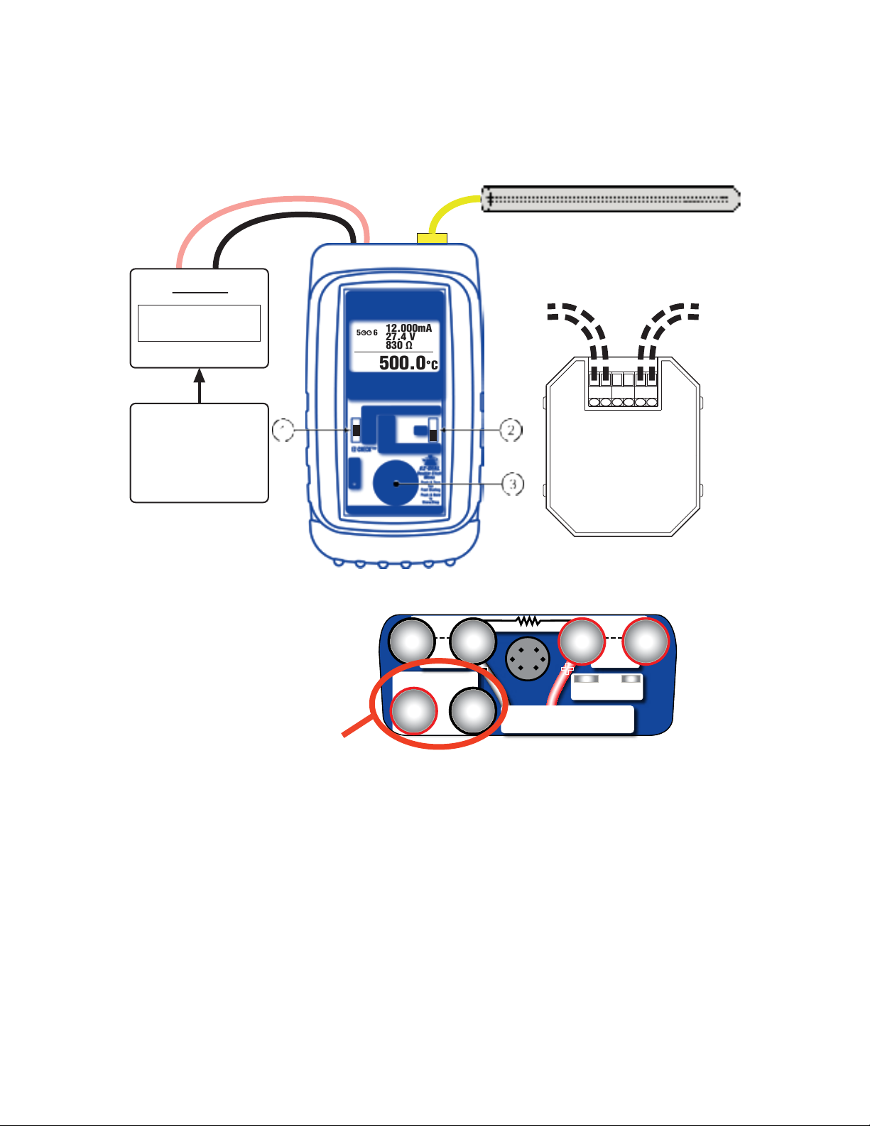
Connecting the 830 in place of a transmitter
Connect the PIE 830 in place of the transmitter. The 4-20 mA
loop connects to the mA jacks of the 830 and the sensor (or
pressure module) connects to the other jacks of the 830.
Receiver
Powers External
2-Wire Transmitter
Power Supply
(2 to 60 VDC)
All milliamp connections
12.000mA
+
-
5 6
27.4 V
830 Ω
500.0
All mA∙ Read V
°C
RTD
+
To
Sensor
23
Ω
-
+
-
Source & Read Hz∙ mV
65
Source V∙ pH
4-20 mA Loop
+ IN - REF +OUT-
Typical
2-Wire
Transmitter
(Disconnected)
4
1
Ω
RTD
-
T/C
To
Note: With LOOPSCOPE on the 830 occasionally performs a
test on the loop. During this short test the loop mA signal will be
affected.
Page 17
Find Quality Products Online at: [email protected]
www.GlobalTestSupply.com
Page 20
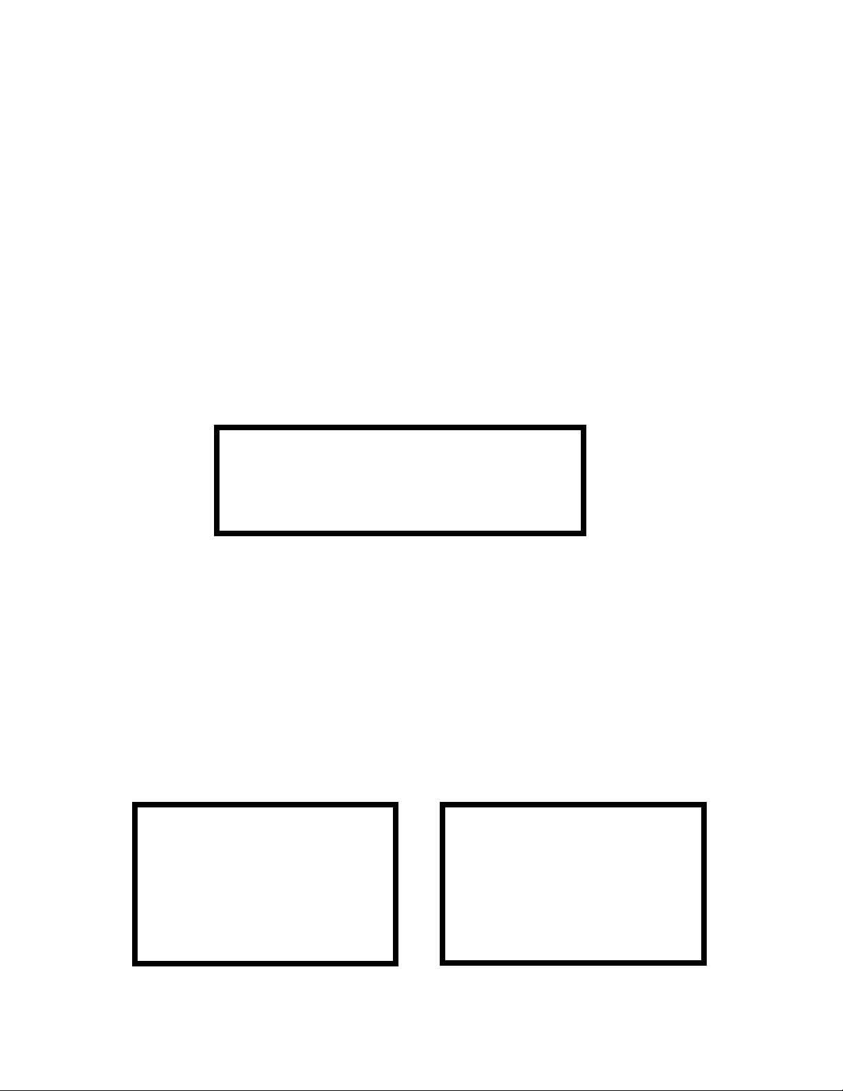
2 Wire SIM mA, 2 Wire SIM % (Percent of 4 to 20 mA)
Choose this function to simulate a 2 Wire Transmitter output from
0.000 to 24.000 milliamps. Operates in loops with power supply
voltages from 2 to 60 VDC.
Move the power switch
EZ-DIAL knob to get into the Menu. Turn the knob to scroll
through the settings and press the knob to make your selection.
Select mA for the FUNCTION and 2W SIM for the MODE.
Choose either mA or % and whether you need the 250Ω HART
resistor active in the loop.
If you would also like to see the condition of the loop turn the
DIAL KNOB to move to the second (or third) menu page so the
word mA DIAGNOSTIC appears at the top of the menu.
> EXIT
LOOPSCOPE OFF ON
LOOPSCOPE turns on the Loop Diagnostic display which
mA DIAGNOSTIC
w to SOURCE then Double Click the
e
simultaneously indicates the current, voltage and resistance of
the loop. When enabled the LOOPSCOPE also indicates errors
by flashing the LED and writing diagnostic messages on the
display. Messages include LOW LOOP VOLT, HIGH LOOP
VOLT and HIGH LOOP IMPED. With LOOPSCOPE on the 830
occasionally performs a test on the loop. During this short test
the loop mA signal will be affected.
2-WIRE
12.000 mA
2-WIRE
SUPPLY 25.4 V
LOAD 485 Ω
12.000 mA
830 with LOOPSCOPE830 Simulating a
Transmitter
Page 18
Find Quality Products Online at: [email protected]
www.GlobalTestSupply.com
Page 21
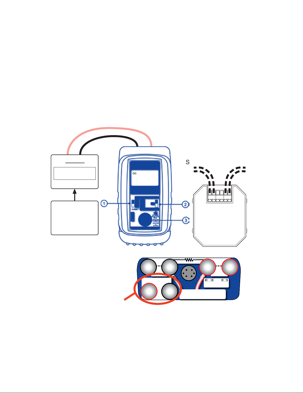
2 Wire SIM mA, 2 Wire SIM % (Percent of 4 to 20 mA)
Connect the output leads of the PIE 830 to the inputs of the
device being calibrated, making sure to check polarity. Red lead
to the plus (+) input and black lead to the minus (-) input.
Instantly output your SPAN and ZERO output settings by moving
the EZ-CHECK switch between HI and LO (defaults to 20 & 4
mA). You may also select any third output setting (such as
mid-range) using the SET position on the EZ-CHECK switch.
The output is adjusted in 0.001 mA (0.01%) increments by
turning the knob
e. Press and turn the knob for faster dialing
with 0.100 mA (1.00%) increments.
Receiver
Powers External
2-Wire Transmitter
Power Supply
(2 to 60 VDC)
2-WIRE
+
-
5 6
4.000mA
LO
To
Sensor
+ IN - REF +OUT-
Typical
2-Wire
Transmitter
(Disconnected)
All milliamp connections
23
Ω
RTD
All mA∙ Read V
+
-
65
-
Source & Read Hz∙ mV
+
Source V∙ pH
4
1
Ω
RTD
-
T/C
Note: With LOOPSCOPE on the 830 occasionally performs a
test on the loop. During this short test the loop mA signal will be
affected.
Page 19
Find Quality Products Online at: [email protected]
www.GlobalTestSupply.com
Page 22
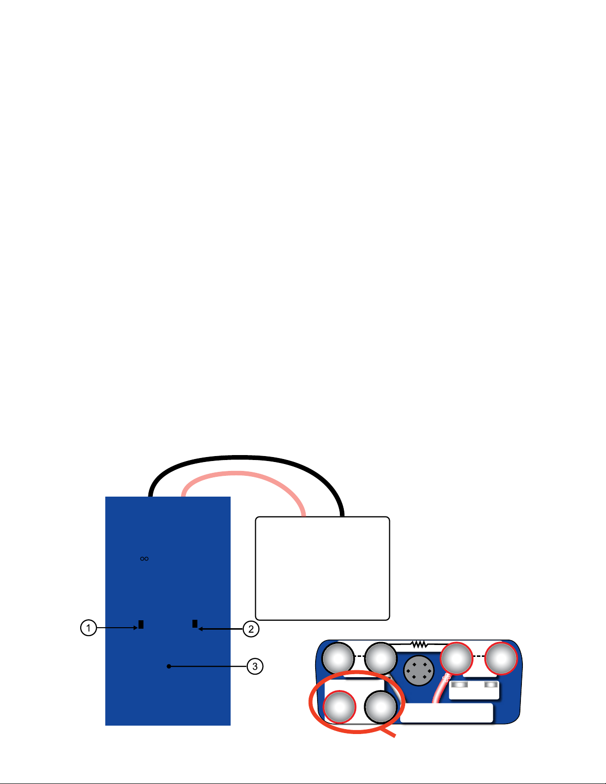
mA SOURCE/ % SOURCE (Percent of 4 to 20 mA)
Choose this function to provide an output from 0.000 to 24.000
milliamps. The compliance voltage is a nominal 24 VDC to
provide the driving power to your milliamp receivers.
Move the power switch
w to SOURCE then Double Click the
EZ-DIAL knob to get into the Menu. Turn the knob to scroll
through the settings and press the knob to make your selection.
Select mA for the FUNCTION and SOURCE for the MODE.
Choose either mA or % and whether you need the 250Ω HART
resistor active in the loop.
Connect the output leads of the PIE 830 to the inputs of the
device being calibrated, making sure to check polarity. Red lead
to the plus (+) input and black lead to the minus (-) input.
Instantly output your SPAN and ZERO output settings by moving
the EZ-CHECK switch between HI and LO (defaults to 20 & 4
mA). You may also select any third output setting (such as
mid-range) using the SET position on the EZ-CHECK switch.
The output is adjusted in 0.001 mA (0.01%) increments by
turning the knob
e. Press and turn the knob for faster dialing
with 0.100 mA (1.00%) increments.
Milliamp Receiver Input
SOURCE
+
-
5 6
20.000mA
HI
Controller
Transmitter
Computer
Logger
I/P
DCS
23
Ω
RTD
All mA∙ Read V
+
-
65
-
Source & Read Hz∙ mV
+
Source V∙ pH
4
1
Ω
RTD
-
T/C
Page 20
Find Quality Products Online at: [email protected]
www.GlobalTestSupply.com
All milliamp connections
Page 23
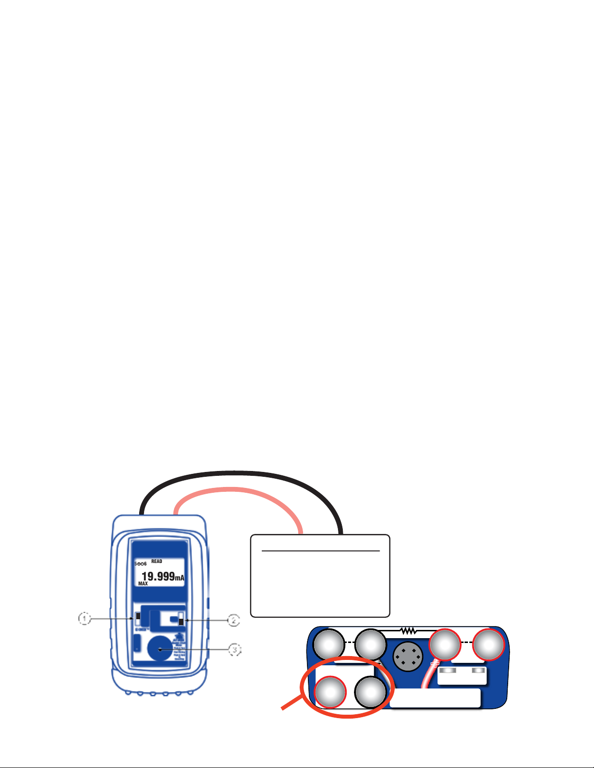
READ mA, READ % (Percent of 4 to 20 mA)
Choose this function to measure from 0.000 to 24.000 milliamps
or -25.00 to 125.00%.
Move the power switch
w to READ then Double Click the
EZ-DIAL knob to get into the Menu. Turn the knob e to scroll
through the settings and press the knob to make your selection.
Select mA for the FUNCTION and READ for the MODE. Choose
either mA or % and whether you need the 250Ω HART resistor
active in the loop.
Connect the red input lead (+) of the PIE 830 to the more
positive point of the break and the black input to the more
negative point.
Signals below 0 mA or open circuits are indicated by 0.000 mA
(-25.00%) on the display. Signals above 24 mA are current
limited by protection circuitry with “OVERRANGE” flashed on the
display and the red OVERLOAD LED lit.
The PIE 830 measures the input signal and constantly updates
the display with the current reading. Move the EZ-CHECK switch
q to MAX to see the highest reading and to MIN to see the
lowest reading. Press and hold the knob e to clear the MAX and
MIN readings.
Milliamp Output Signal
READ
+
-
5 6
19.999mA
MAX
All milliamp connections
Controller
Transmitter
P/I
DCS
RTD
All mA∙ Read V
+
23
Ω
-
+
-
Source & Read Hz∙ mV
65
Source V∙ pH
4
1
Ω
RTD
-
T/C
Page 21
Find Quality Products Online at: [email protected]
www.GlobalTestSupply.com
Page 24
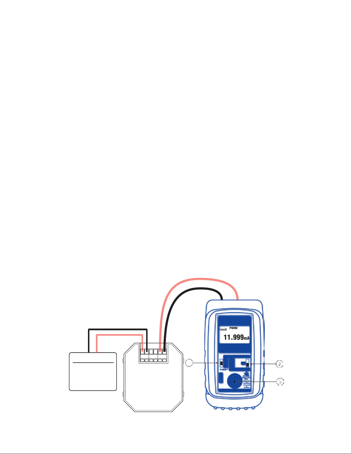
Power/Measure mA, Power/Measure % (Percent of 4 to 20 mA)
Choose this function to simultaneously supply power to a 2 Wire
Transmitter while displaying the 4.000 to 20.000 mA output of
the transmitter.
Move the power switch
w to READ then Double Click the
EZ-DIAL knob to get into the Menu. Turn the knob e to scroll
through the settings and press the knob to make your selection.
Select mA for the FUNCTION and PWR MEAS for the MODE.
Choose either mA or % and whether you need the 250Ω HART
resistor active in the loop.
Disconnect one or both input wires from the device to be
calibrated. Connect the red source lead of the PIE 830 to the
plus (+) input of the device and the black source lead to the
minus (-).
The PIE 830 supplies a nominal 24 volts DC at 24 mA to the 2
Wire Transmitter. The current passed by the transmitter will be
accurately displayed by the PIE 830. Calibrate the transmitter in
the usual manner and disconnect the PIE 830. Signals above 24
mA are current limited by protection circuitry with “OVERRANGE”
flashed on the display and the red OVERLOAD LED lit.
PWRM
+
-
5 6
11.999mA
Transmitter Input
Sensor
Process Signal
Simulated Input
+ IN - REF +OUT-
Typical
2-Wire
Transmitter
HI
SET
LO
SOURCE
MAX
READ
MIN
READ
Page 22
Find Quality Products Online at: [email protected]
www.GlobalTestSupply.com
Page 25
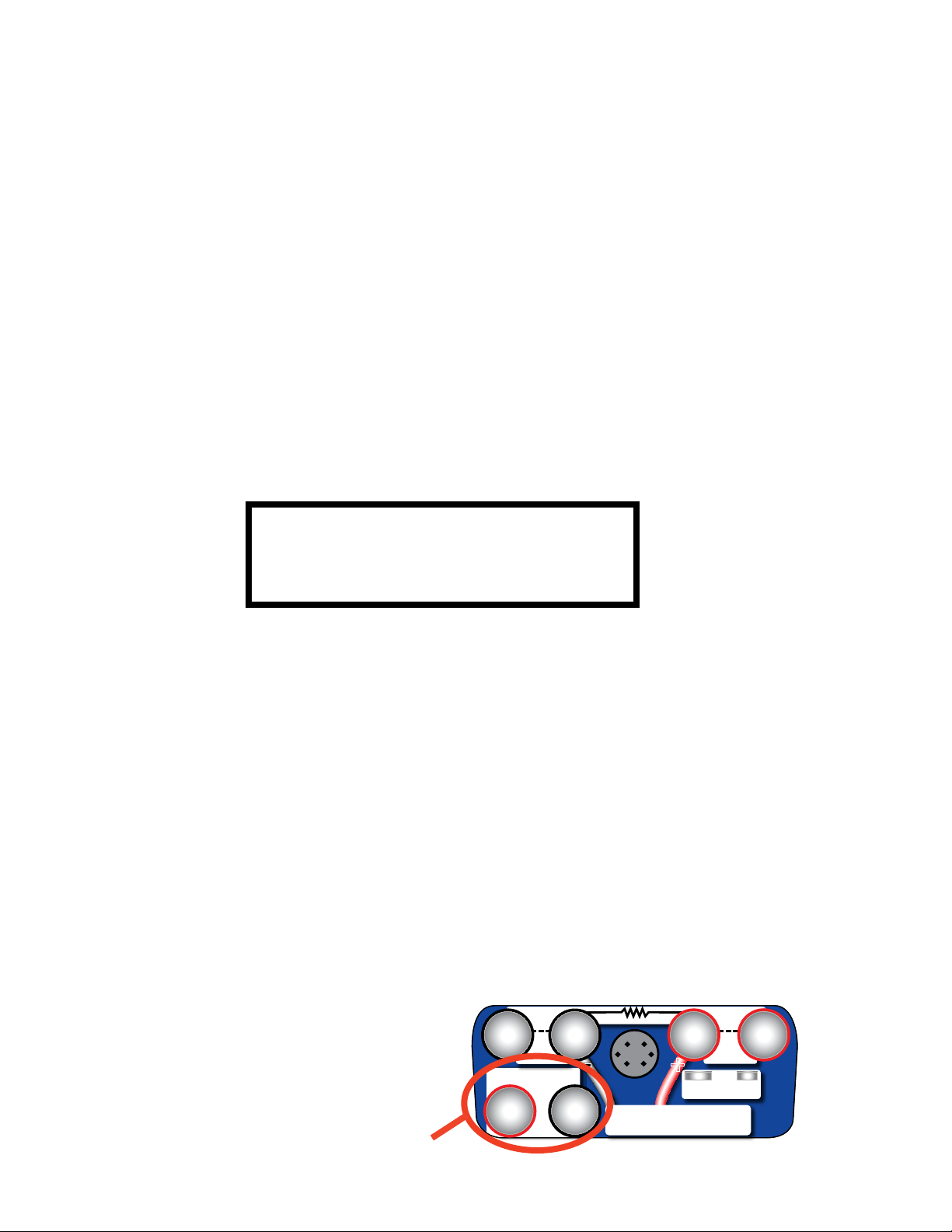
Using Ground Leak Detection
mA OUT, % OUT (Percent of 4 to 20 mA)
Find current leaks in loops caused by ground faults, moisture or
corrosion. The 830 simultaneously supplies power to a 2 Wire
Transmitter (or loop with a transmitter) while displaying the 4 to
20 mA output and the amount of current leaking in the loop.
1) Move the power switch
w to READ then Double Click the
EZ-DIAL knob to get into the Menu. Turn the knob e to scroll
through the settings and press the knob to make your selection. Select mA for the FUNCTION and PWR MEAS for the
MODE. Choose either mA or %.
2) Turn the knob
e until the following menu appears.
mA DIAGNOSTIC
> EXIT
LEAK DETECT OFF ON
3) Turn the knob
e to scroll through the settings and press the
knob to make your selection. Turn on the LEAK DETECT.
4) Connect the red source lead from the mA (+) jack of the 830
to the plus (+) input of the device and the black source lead
from the mA (-) to the minus (-).
The PIE 830 supplies a nominal 24 volts DC at 24 mA to the 2
Wire Transmitter or loop. The current passed by the transmitter
will be accurately displayed by the 830 along with an indication
of leakage current at the top of the display. If there is an
uncontrolled loop, a transmitter with upscale burnout and bad or
missing sensor or a short the display shows "OVER RANGE”
All milliamp connections
23
Ω
RTD
All mA∙ Read V
+
-
65
-
Source & Read Hz∙ mV
+
Source V∙ pH
4
1
Ω
RTD
-
T/C
Page 23
Find Quality Products Online at: [email protected]
www.GlobalTestSupply.com
Page 26
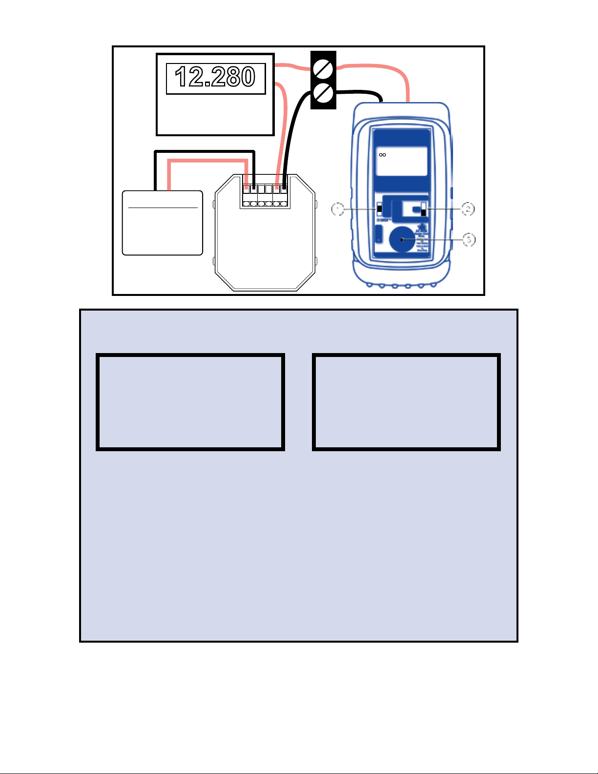
Using Ground Leak Detection
12.280
PROCESS
INDICATOR
PWRM LEAK
+
-
5 6
00.28 mA
12.280mA
Transmitter Input
Sensor
Process Signal
Simulated Input
+ IN - REF +OUT-
Typical
2-Wire
Transmitter
Typical Error Conditions
PWRM LEAK
12.280 mA
The PIE 830 is supplying
00.28 mA
PWRM LEAK
mA
OVER RANGE
mA
The PIE 830 is supplying
the loop voltage. A
calibrated transmitter is
limiting the loop current to
12.00 mA. An additional
0.28 mA is not controlled
by the transmitter and is
the loop voltage. There is a
control loop error. This may
be a transmitter (set for
upscale burnout) with a
bad or missing sensor, or a
short in the loop.
leaking somewhere in the
loop.
Note: Many installed transmitters will normally indicate 0.01 to
0.02 mA leakage without significant control problem. Unstable
readings may indicate loose connections or the presence of
moisture.
Page 24
Find Quality Products Online at: [email protected]
www.GlobalTestSupply.com
Page 27
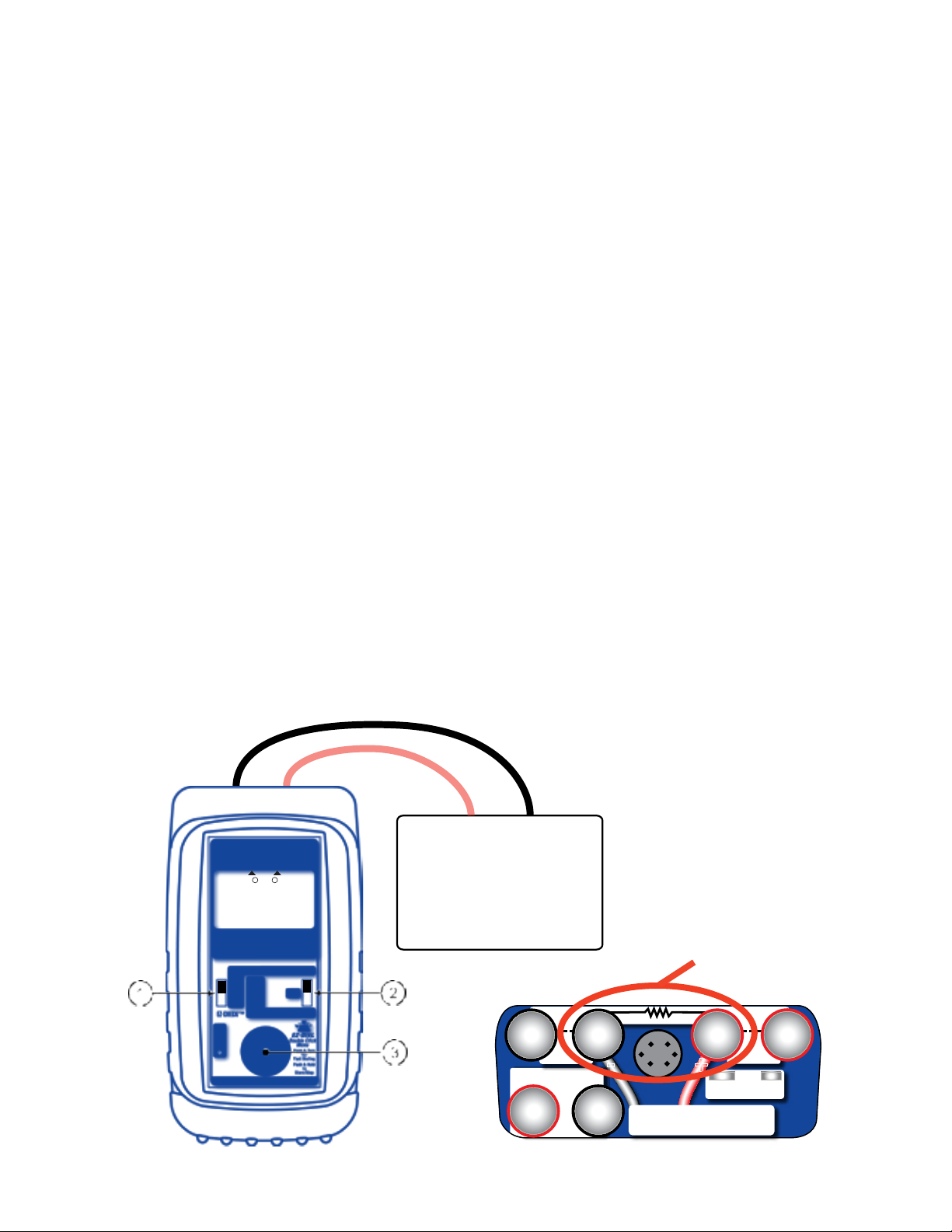
mV/V SOURCE
Choose this function to provide an output from -20.000 to 99.999
mV, -500.00 TO 999.99 mV or from 0.000 to 10.250 V. The
source current is a nominal 20 mA to provide the driving power
to your voltage receivers.
Move the power switch
w to SOURCE then Double Click the
EZ-DIAL knob to get into the Menu. Turn the knob to scroll
through the settings and press the knob to make your selection.
Select V for the FUNCTION and 1 V, 10V or 100 mV for the
RANGE.
Connect the output leads of the PIE 830 to the inputs of the
device being calibrated, making sure to check polarity. Red lead
to the plus (+) input and black lead to the minus (-) input.
Instantly output your SPAN and ZERO output settings by moving
the EZ-CHECK switch between HI and LO. You may also select
any third output setting (such as mid-range) using the SET
position on the EZ-CHECK switch. The output is adjusted in
0.001 mV, 0.01 mV or 0.001 V increments by turning the knob
e.
Press and turn the knob for faster dialing with 0.100 mV, 1.00 mV
or 0.100 V increments.
Voltage Receiver Input
+
-
2 1
5.000V
HI
Controller
Transmitter
Computer
Logger
DCS
All mA∙ Read V
Ω
RTD
+
V & mV Source
23
-
+
-
Source & Read Hz∙ mV
65
Source V∙ pH
4
1
Ω
RTD
-
T/C
Page 25
Find Quality Products Online at: [email protected]
www.GlobalTestSupply.com
Page 28
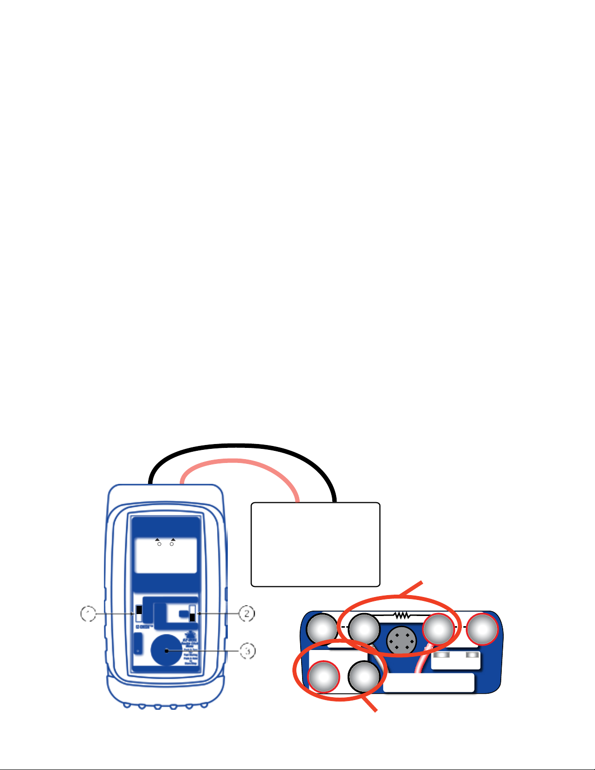
Read mV/V
Choose this function to measure from -99.999 to 99.999
millivolts, -999.99 to +999.99 mV, 0.000 to 10.250 V dc or 0.00
to 60.00 V dc.
Move the power switch
w to READ then Double Click the
EZ-DIAL knob to get into the Menu. Turn the knob to scroll
through the settings and press the knob to make your selection.
Select V for the FUNCTION and 1V, 10V, 60V or 100 mV for the
RANGE.
Connect the red input lead (+) of the PIE 830 to the more
positive point of the break and the black input to the more
negative point.
Signals above the maximum scale are limited by protection
circuitry with “OVER RANGE” flashed on the display and the red
OVERLOAD LED lit.
The PIE 830 measures the input signal and constantly updates
the display with the current reading. Move the EZ-CHECK switch
q to MAX to see the highest reading and to MIN to see the
lowest reading. Press and hold the knob e to clear the MAX and
MIN readings.
Voltage Output Signal
+
-
2 1
8.300mV
MAX
Controller
Transmitter
Power Supply
RTD
All mA∙ Read V
+
Connections for
Read mV ranges
23
Ω
-
+
-
Source & Read Hz∙ mV
65
Source V∙ pH
4
1
Ω
RTD
-
T/C
Connections for Read
10 V & 60V ranges
Page 26
Find Quality Products Online at: [email protected]
www.GlobalTestSupply.com
Page 29
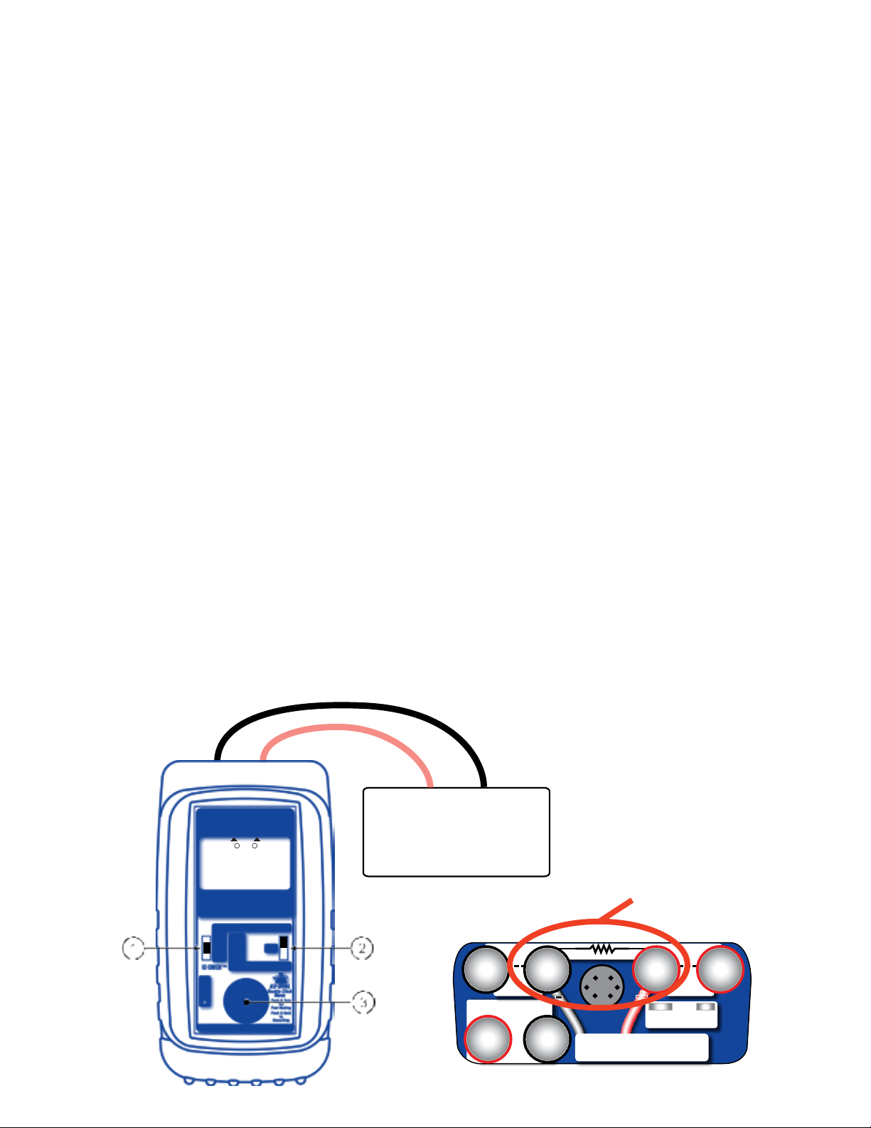
pH SOURCE
Choose this function to provide an output from 0.000 to 14.000
pH @ 25°C (77°F) which corresponds to 414.12 to -414.12 mV.
The source current is a nominal 20 mA to provide the driving
power to your pH receivers.
Move the power switch
w to SOURCE then Double Click the
EZ-DIAL knob to get into the Menu. Turn the knob to scroll
through the settings and press the knob to make your selection.
Select pH for the FUNCTION.
Connect the output leads of the PIE 830 to the inputs of the
device being calibrated, making sure to check polarity. Red lead
from the mV (+) jack of the 830 to the plus (+) input and black
lead from the mV (-) jack to the minus (-) input.
Instantly output your SPAN and ZERO output settings by moving
the EZ-CHECK switch between HI and LO. You may also select
any third output setting (such as mid-range) using the DIAL
position on the EZ-CHECK switch. The output is adjusted in
0.001 pH increments by turning the knob
e. Press and turn the
knob for faster dialing with 0.100 pH increments.
pH Receiver Input
+
-
2 1
4.010pH
ACID
Controller
Transmitter
Analyzer
All mA∙ Read V
Ω
RTD
+
pH Source
23
-
+
-
Source & Read Hz∙ mV
65
Source V∙ pH
4
1
Ω
RTD
-
T/C
Page 27
Find Quality Products Online at: [email protected]
www.GlobalTestSupply.com
Page 30

Simulate pH probes into transmitters & analyzers
Use the pH simulator to verify proper operation of pH devices
before you place a probe into a calibrated buffer. Adjusting the
pH transmitter or analyzer without a probe allows you to make
sure the device is calibrated and operating correctly. The 830
simulates 0.000 to 14.000 pH @ 25°C corresponding to 414.12
to -414.12 mV.
Once the pH instrument has been adjusted against the PIE 830
reconnect the pH probe and check it against the proper buffer
(typically 7 pH). If the instrument zero point requires more than
the manufacturer’s recommendations (typically within 0.5 pH) it
is time to clean or replace the probe.
Page 28
Find Quality Products Online at: [email protected]
www.GlobalTestSupply.com
Page 31
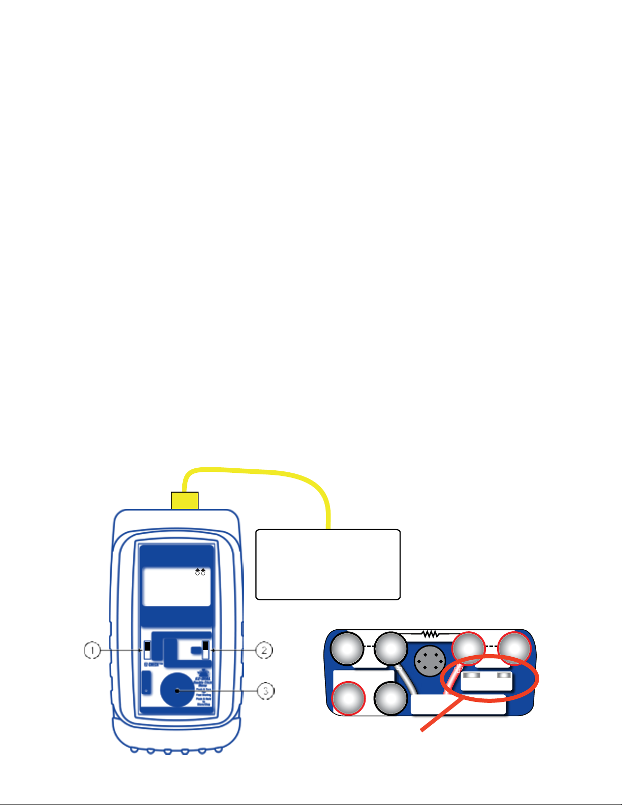
Thermocouple Source
Choose this function to provide a simulated thermocouple signal
into controllers, temperature transmitters, indicators or any input
devices that measure thermocouple sensors.
Move the power switch
w to SOURCE then Double Click the
EZ-DIAL knob to get into the Menu. Turn the knob to scroll
through the settings and press the knob to make your selection.
Select T/C for the FUNCTION, °F or °C for the UNITS, T/C Type
(J, K, E, T, R, S, B, N, L (J-DIN), U (T-DIN), G, C, D or P (Platinel
II)) and internal COLD JUNC ON or OFF (ON is the default).
Connect the PIE 830 to the inputs of the device being calibrated
using the proper type of thermocouple wire via the miniature
thermocouple socket.
Instantly output your SPAN and ZERO output settings by moving
the EZ-CHECK switch between HI and LO. You may also select
any third output setting (such as mid-range) using the SET
position on the EZ-CHECK switch. The output is adjusted in 0.1°
increments by turning the knob
e. Press and turn the knob for
faster dialing with 10.0° increments.
-
T/C
1083.0°C
HI
TYPE K
Thermocouple Wire
Instrument with T/C Input
+
Temperature Transmitter
Temperature Indicator
Temperature Trip or Alarm
Page 29
Controller
23
Ω
RTD
All mA∙ Read V
+
All thermocouple connections
-
-
Source & Read Hz∙ mV
65
Source V∙ pH
+
4
1
Ω
RTD
-
T/C
Find Quality Products Online at: [email protected]
www.GlobalTestSupply.com
Page 32
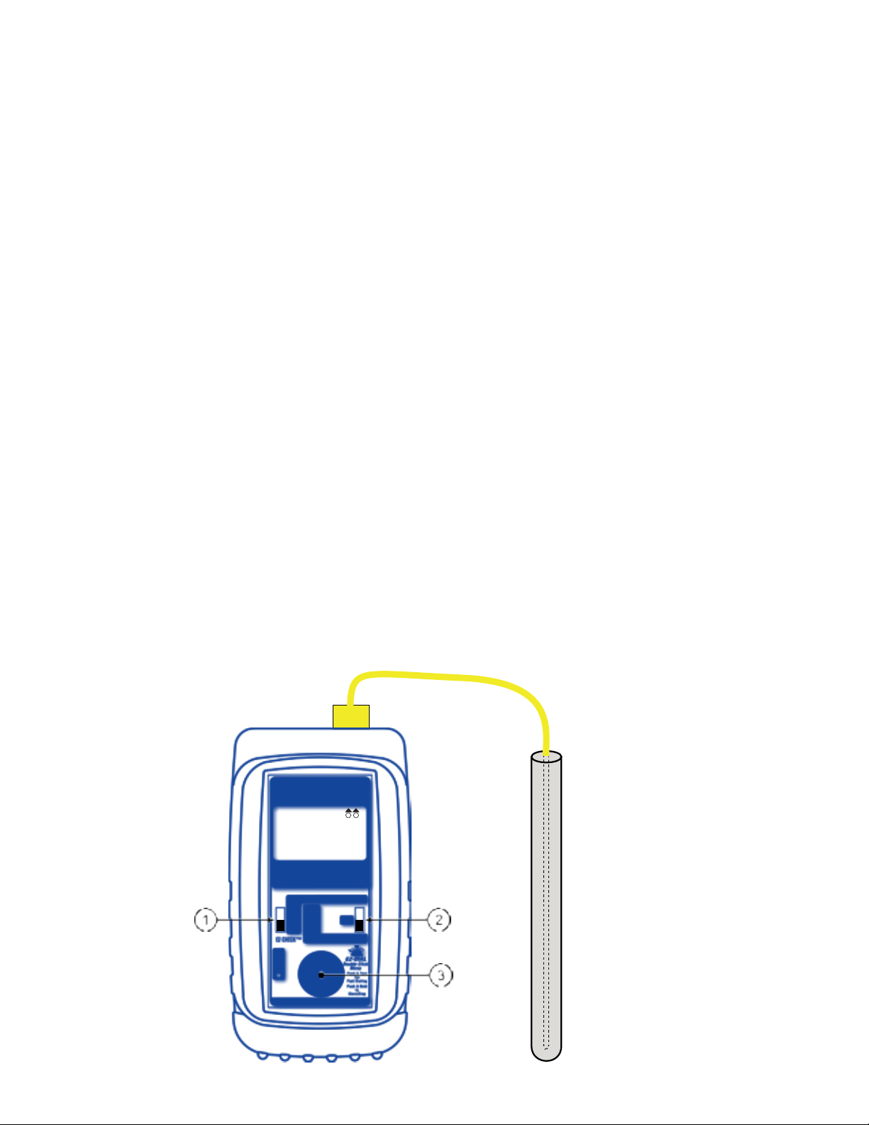
Read Thermocouple Sensors
Choose this function to measure temperatures with a
thermocouple probe, sensor or any device that output a
thermocouple signal.
Move the power switch
w to READ then Double Click the
EZ-DIAL knob to get into the Double Click Menu. Turn the knob
to scroll through the settings and press the knob to make your
selection. Select T/C for the FUNCTION, °F or °C for the UNITS,
T/C Type (J, K, E, T, R, S, B, N, L (J-DIN), U (T-DIN), G, C, D or
P (Platinel II)) and COLD JUNC ON or OFF (ON is the default).
Connect the PIE 830 to the inputs of the device being calibrated
using the proper type of thermocouple wire via the miniature
thermocouple socket. If no sensor is connected, a wire is broken
or the sensor is burned out, OPEN TC will appear on the display.
Signals above the maximum scale are limited by protection
circuitry with “OVER RANGE” on the display and the OVERLOAD
LED blinks red.
The PIE 830 measures the input signal and constantly updates
the display with the current reading. Move the EZ-CHECK switch
q to MAX to see the highest reading and to MIN to see the
lowest reading. Press and hold the knob e to clear the MAX and
MIN readings.
Thermocouple Wire
+
-
T/C
830.0 °C
MIN
TYPE K
Page 30
Find Quality Products Online at: [email protected]
www.GlobalTestSupply.com
Page 33
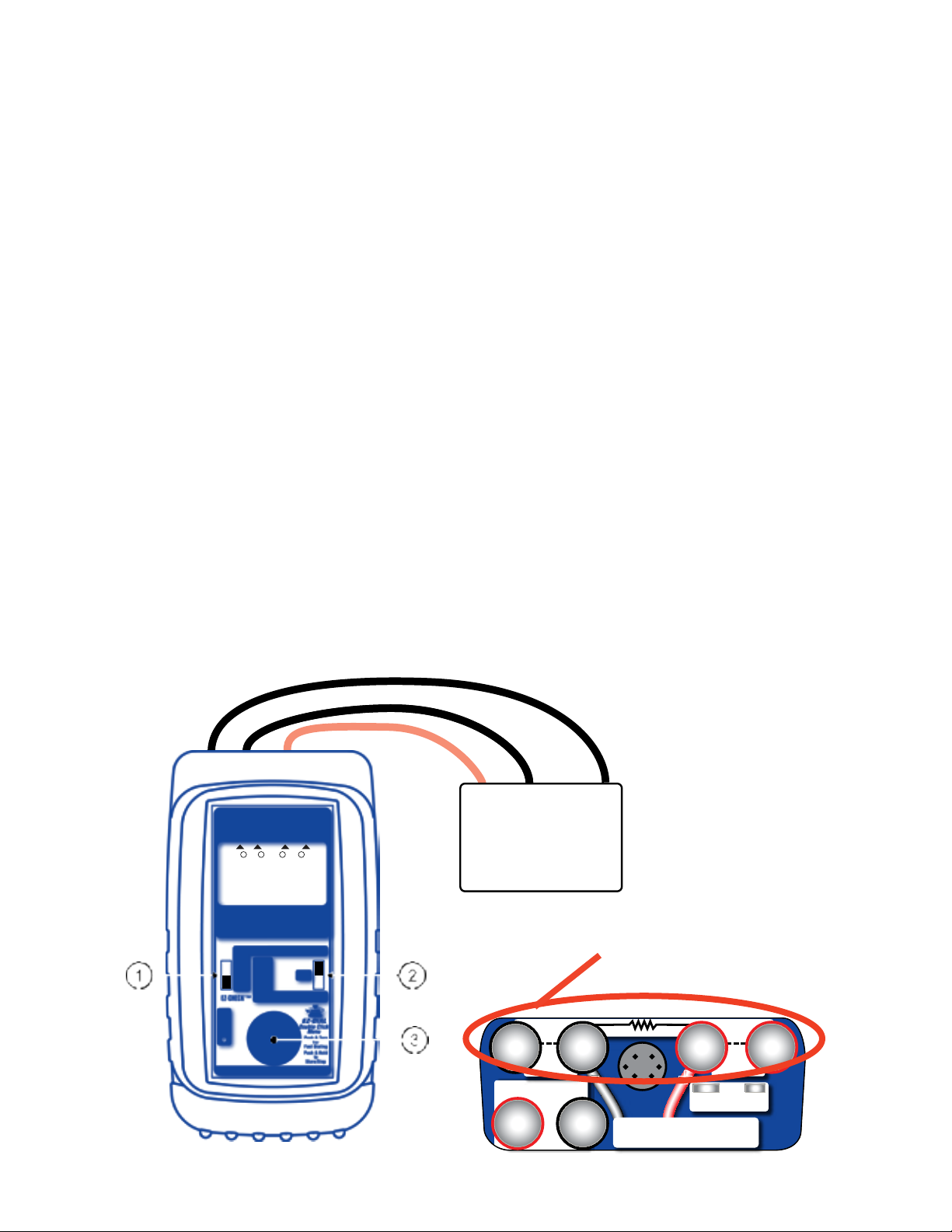
Resistance Source
Choose this function to provide a simulated resistance into any
device that measures resistance.
Move the power switch
w to SOURCE then Double Click the
EZ-DIAL knob to get into the Menu. Turn the knob to scroll
through the settings and press the knob to make your selection.
Select OHMS for the FUNCTION, 400Ω or 4000Ω for the
RANGE.
Disconnect all sensor wires from the devices to be calibrated
and connect the PIE 830 to the inputs of the device using 2, 3
or 4 wires.
Instantly output your SPAN and ZERO output settings by moving
the EZ-CHECK switch between HI and LO. You may also select
any third output setting (such as mid-range) using the SET
position on the EZ-CHECK switch. The output is adjusted in
0.01Ω/0.1Ω increments by turning the knob
e. Press and turn
the knob for faster dialing with 1.00Ω/10.0Ω increments.
Instrument with
Resistance Input
+-+
-
2 1
3 4
250.00 Ω
LO
Controller
Transmitter
PLC
2, 3 & 4 Wire Resistance Connections
23
Ω
RTD
All mA∙ Read V
+
-
65
-
Source & Read Hz∙ mV
+
Source V∙ pH
4
1
Ω
RTD
-
T/C
Page 31
Find Quality Products Online at: [email protected]
www.GlobalTestSupply.com
Page 34
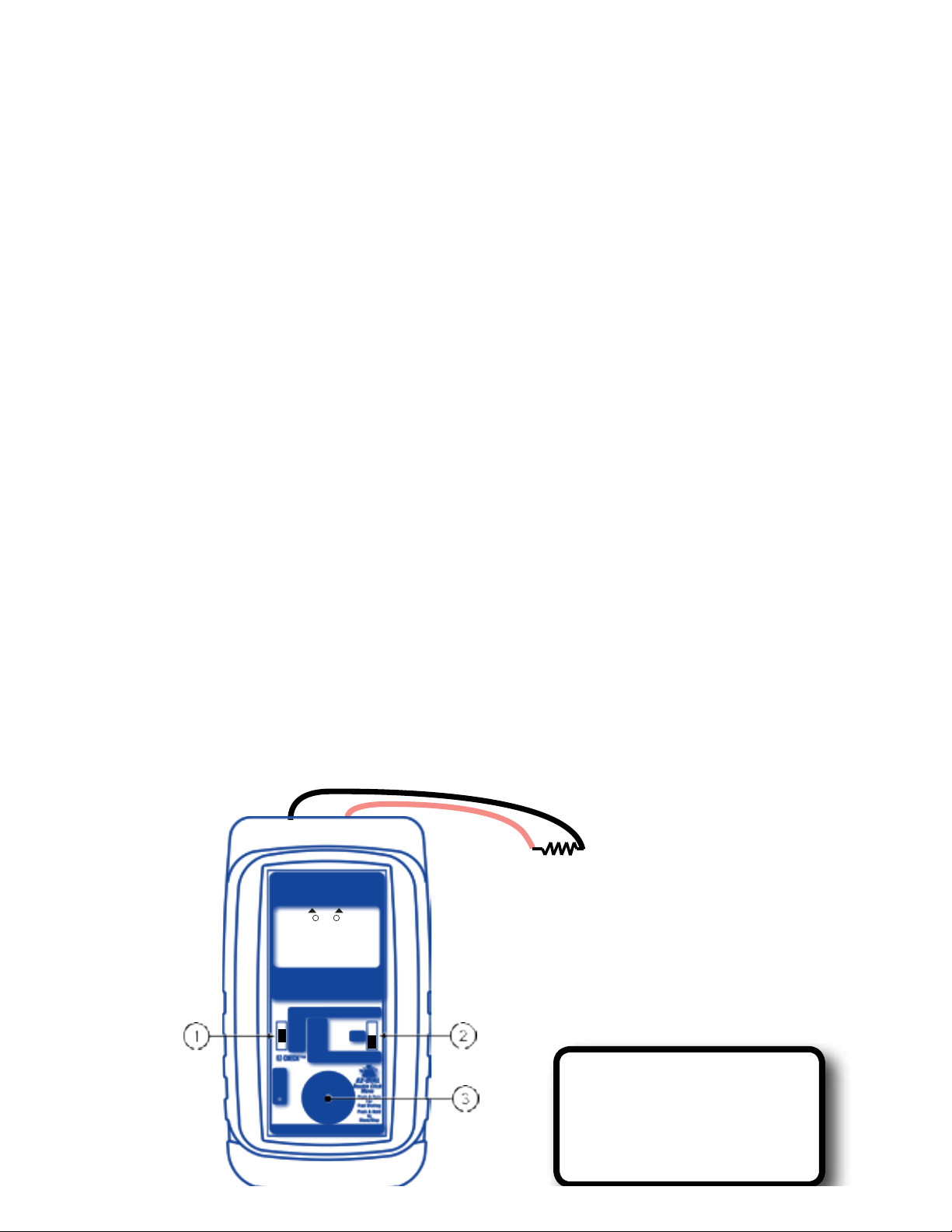
Read Resistance & Check Continuity
Choose this function to measure resistance or check continuity.
Move the power switch
w to READ then Double Click the
EZ-DIAL knob to get into the Double Click Menu. Turn the knob
to scroll through the settings and press the knob to make your
selection. Select OHMS for the FUNCTION, 400Ω, 4000Ω or
Continuity for the RANGE.
Connect the PIE 830 to the resistor or sensor using 2, 3 or 4
wires. The PIE 830 automatically detects how many wires are
connected using a patented circuit and indicates each wire that
is connected. Any wires that are not connected or broken are
indicated by the 830. This is useful for troubleshooting the sensor.
If continuity is selected, resistance is measured up to 400.0Ω.
The beeper will sound and
)))) appears on the display when
resistance below 100.0Ω is measured.
Signals above the maximum scale are limited by protection
circuitry with “OVER RANGE” flashed on the display and the
OVERLOAD LED blinks red.
The PIE 830 measures the input signal and constantly updates
the display with the current reading. Move the EZ-CHECK switch
q to MAX to see the highest reading and to MIN to see the
lowest reading. Press and hold the knob e to clear the MAX and
MIN readings.
+
-
2 1
830.00 Ω
Page 32
Find Quality Products Online at: [email protected]
www.GlobalTestSupply.com
Page 35
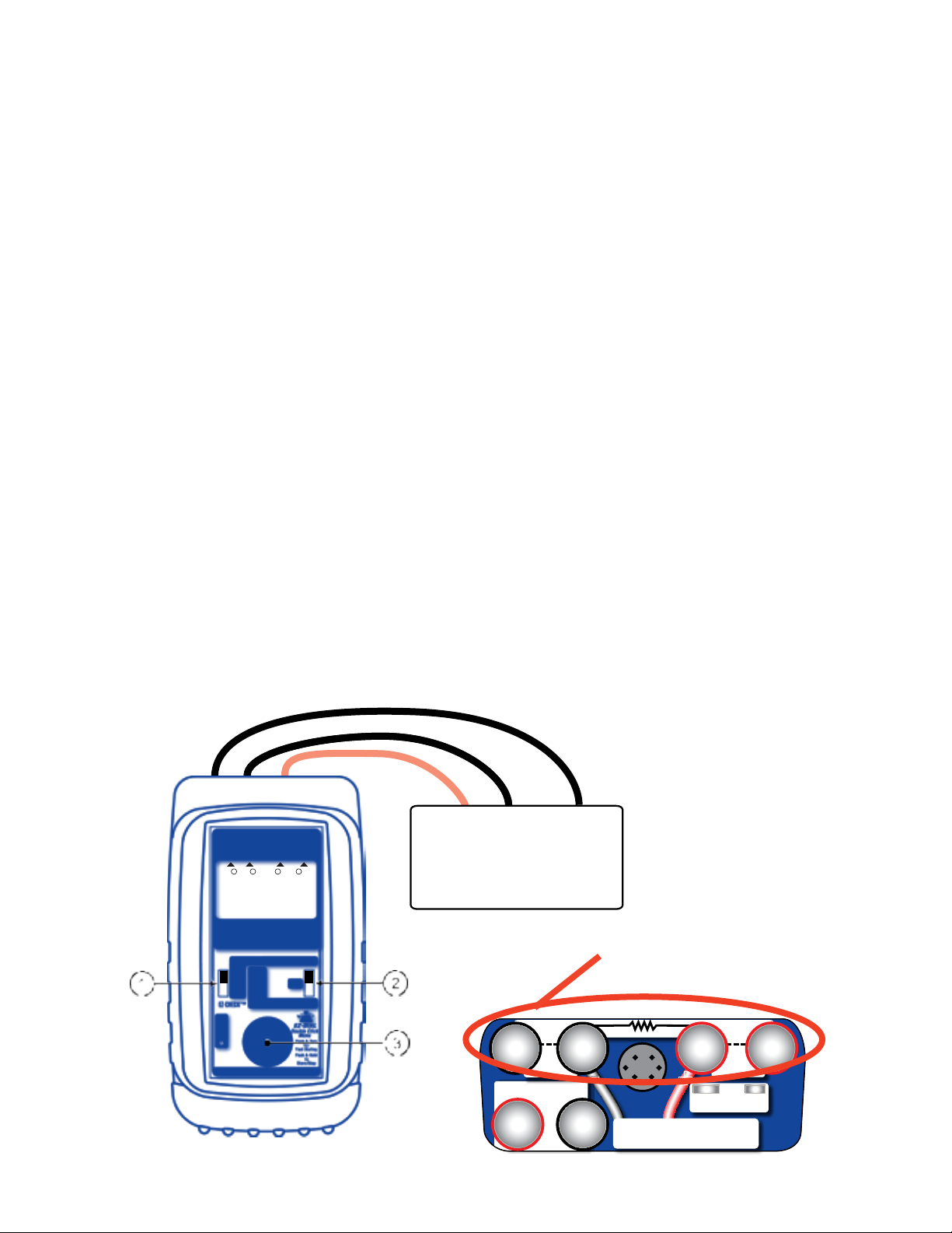
RTD Source
Choose this function to provide a simulated RTD signal into
controllers, temperature transmitters, indicators or any input
devices that measure RTD sensors.
Move the power switch
w to SOURCE then Double Click the
EZ-DIAL knob to get into the Menu. Turn the knob to scroll
through the settings and press the knob to make your selection.
Select RTD for the FUNCTION, °F or °C for the UNITS and RTD
(Choose from one of Platinum 100Ω, or 1000Ω, Copper 10Ω or
50Ω, Nickel 120Ω or 110Ω curves). Note: Pt 100Ω 3850 is the
most common RTD type.
Disconnect all sensor wires from the devices to be calibrated
and connect the PIE 830 to the inputs of the device using 2, 3
or 4 wires.
Instantly output your SPAN and ZERO output settings by moving
the EZ-CHECK switch between HI and LO. You may also select
any third output setting (such as mid-range) using the SET
position on the EZ-CHECK switch. The output is adjusted in 0.1°
increments by turning the knob
e. Press and turn the knob for
faster dialing with 10.0° increments.
Instrument with RTD Input
Controller
+-+
-
2 1
3 RTD 4
830.0 °C
HI
Pt 100 α=3850
Temperature Transmitter
Temperature Indicator
Temperature Trip or Alarm
All mA∙ Read V
2, 3 & 4 Wire RTD Connections
Ω
RTD
+
23
-
+
-
Source & Read Hz∙ mV
65
Source V∙ pH
4
1
Ω
RTD
-
T/C
Page 33
Find Quality Products Online at: [email protected]
www.GlobalTestSupply.com
Page 36
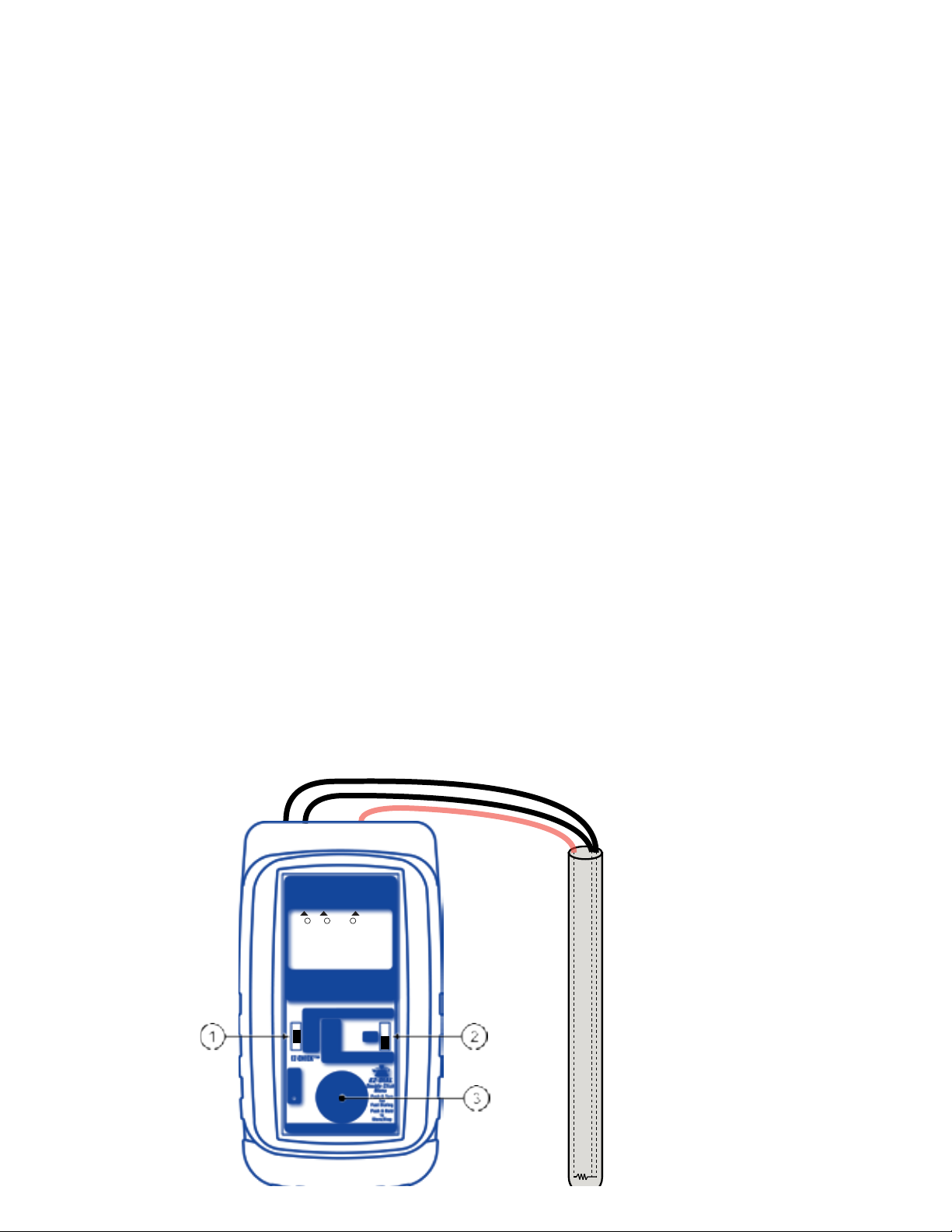
Read RTD Sensors
Choose this function to measure temperatures with an RTD
probe, sensor or any device that output an RTD signal.
Move the power switch
w to READ then Double Click the
EZ-DIAL knob to get into the Menu. Turn the knob to scroll
through the settings and press the knob to make your selection.
Select RTD for the FUNCTION, °F or °C for the UNITS and RTD
(Choose from one of Platinum 100Ω, or 1000Ω, Copper 10Ω or
50Ω, Nickel 120Ω or 110Ω curves). Note: Pt 100Ω 3850 is the
most common RTD type.
Connect the PIE 830 to the RTD sensor using 2, 3 or 4 wires. The
PIE 830 automatically detects how many wires are connected
using a patented circuit and indicates each wire that is connected.
Any wires that are not connected or broken are indicated by the
830. This information is useful for troubleshooting the sensor.
Signals above the maximum scale are limited by protection
circuitry with “OVER RANGE” flashed on the display and the red
OVERLOAD LED lit.
The PIE 830 measures the input signal and constantly updates
the display with the current reading. Move the EZ-CHECK switch
q to MAX to see the highest reading and to MIN to see the
lowest reading. Press and hold the knob e to clear the MAX and
MIN readings.
+
-
-
2 1
3 RTD
83.0 °C
Pt 100 α=3850
Page 34
Find Quality Products Online at: [email protected]
www.GlobalTestSupply.com
Page 37
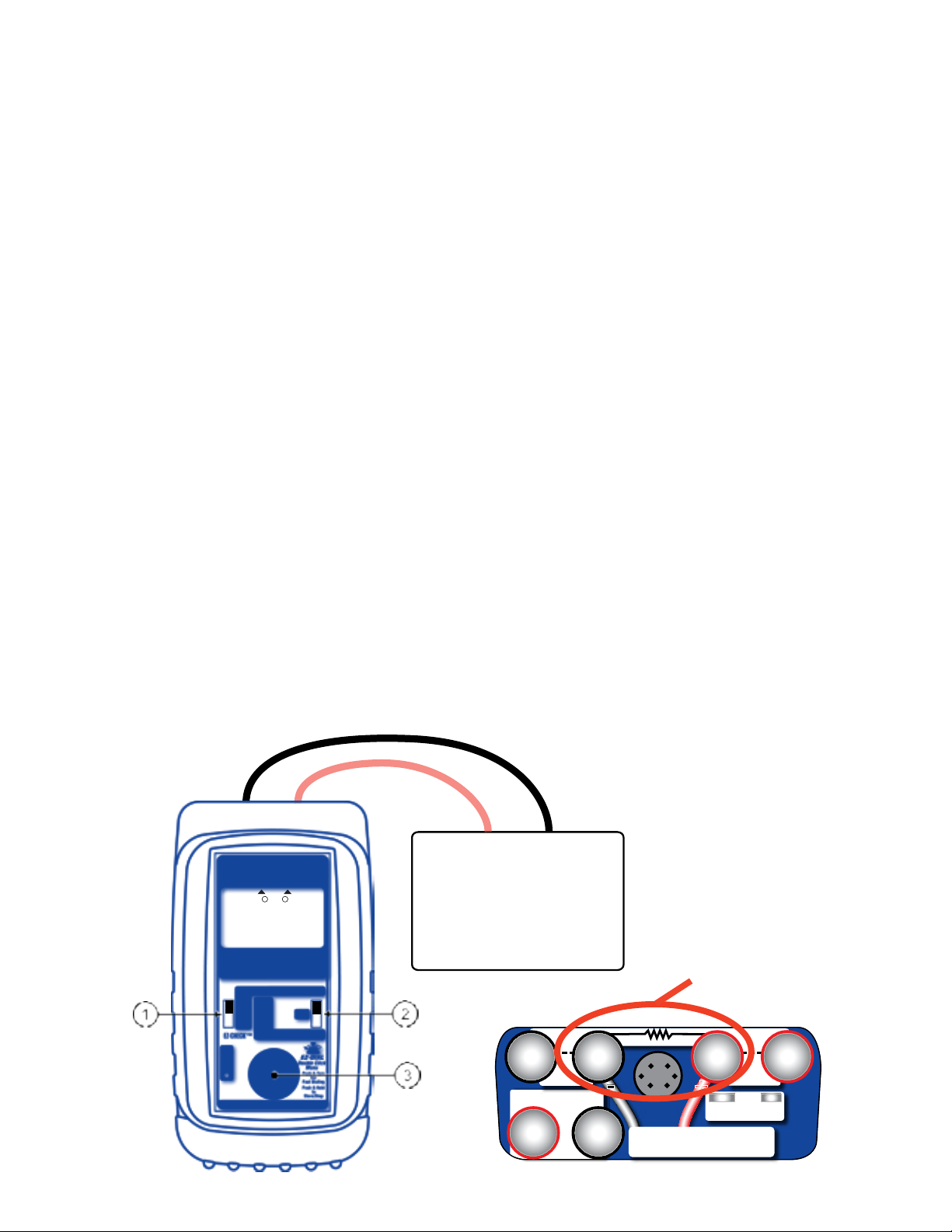
Frequency Source
Choose this function to provide a frequency signal into any input
devices that measure frequency.
Move the power switch
w to SOURCE then Double Click the
EZ-DIAL knob to get into the Menu. Turn the knob to scroll
through the settings and press the knob to make your selection.
Select FREQ for the FUNCTION and 20KHZ, 10000HZ, 1000HZ
or 2000CPM for the RANGE.
Disconnect all input wires from the devices to be calibrated and
connect the PIE 830 to the input of the device matching polarity.
The green HZ SYNC LED pulses in synch with the output pulses
and may be used to calibrate optical pickups. The output signal
is a zero crossing square wave with a fixed amplitude of 6 V
peak-to-peak from -1 and + 5 V.
Instantly output your SPAN and ZERO output settings by moving
the EZ-CHECK switch between HI and LO. You may also select
any third output setting (such as mid-range) using the SET
position on the EZ-CHECK switch. The output is adjusted in 1
count increments by turning the knob
e. Press and turn the
knob for faster dialing with 100 count increments.
Frequency Receiver Input
Flowmeter
+
-
2 1
8300.0Hz
HI
Transmitter
Computer
Logger
Controller
DCS
All mA∙ Read V
Ω
RTD
+
All Frequency
Connections
23
-
+
-
Source & Read Hz∙ mV
65
Source V∙ pH
4
1
Ω
RTD
-
T/C
Page 35
Find Quality Products Online at: [email protected]
www.GlobalTestSupply.com
Page 38
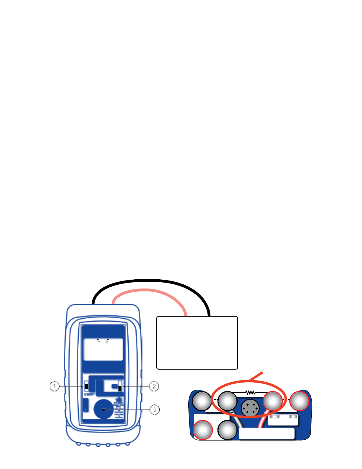
Read Frequency
Choose this function to count frequency.
Move the power switch
w to READ then Double Click the
EZ-DIAL knob to get into the Menu. Turn the knob to scroll
through the settings and press the knob to make your selection.
Select FREQ for the FUNCTION and 20KHZ, 10000HZ, 1000HZ
or 2000CPM for the RANGE.
Disconnect all input wires from the devices to be calibrated and
connect the PIE 830 to the output of the device matching
polarity.
The green HZ SYNC LED pulses in synch with the input
frequency.
Signals above the maximum scale are limited by protection
circuitry with “OVER RANGE” flashed on the display and the red
OVERLOAD LED lit.
The PIE 830 measures the input signal and constantly updates
the display with the current reading. Move the EZ-CHECK switch
q to MAX to see the highest reading and to MIN to see the
lowest reading. Press and hold the knob e to clear the MAX and
MIN readings.
Frequency Output Signal
Flowmeter
+
-
2 1
830.00 Hz
Flow Sensor
Variable Speed Drive
Controller
Transmitter
23
Ω
RTD
All mA∙ Read V
+
-
65
Page 36
All Frequency
Connections
-
Source & Read Hz∙ mV
+
Source V∙ pH
4
1
Ω
RTD
-
T/C
Find Quality Products Online at: [email protected]
www.GlobalTestSupply.com
Page 39

Read Pressure
Choose this function to measure pressure in one of 32 different
engineering units using a PIE Pressure Module.
1) Move the power switch w to READ then Double Click the
EZ-DIAL knob to get into the Menu. Turn the knob to scroll
through the settings and press the knob to make your selection.
Select PRESSURE for the FUNCTION and make your choice of
UNITS to match the pressure instrument to be checked.
2) Remove the covers from the ends of the connector on the
pressure module cable and the pressure connector of the 830.
Align the white arrows and plug the cable into the 830.
3) Connect pressure hoses, fittings & pumps (if required) to the
pressure instrument to be checked.
4) Press and hold the
e E-Z DIAL KNOB for 2 seconds (after
MAX/MIN RESET appears) to 'Zero' or 'Tare' the pressure. The
display will briefly display 'TARE ON' then a '0' appears on the
display indicating that all measurements are relative to the
pressure measured when the calibrator was zeroed. Press and
hold the
e E-Z DIAL KNOB for 2 seconds (after MAX/MIN
RESET appears) when you want to turn the 'Tare' off.
The PIE 830 measures the pressure and constantly updates the
display with the current reading. Move the EZ-CHECK switch
q
to MAX to see the highest reading and to MIN to see the lowest
reading. Press and hold the knob e for 1 second to clear the
MAX and MIN readings.
To disconnect the pressure module gently pull up on the groved
area just above the white arrow.
Port for Pressure Module
23
Ω
RTD
All mA∙ Read V
+
-
65
-
Source & Read Hz∙ mV
+
Source V∙ pH
4
1
Ω
RTD
-
T/C
Page 37
Find Quality Products Online at: [email protected]
www.GlobalTestSupply.com
Page 40

PIE 830 with Pressure Module,
Pressure/Vacuum Pump & Hose
Hands free carrying case with pockets for the PIE 830 and
the pressure module. Back of the case has a zippered pocket
for the manual, test leads, hoses and pressure fittings.
Page 38
Find Quality Products Online at: [email protected]
www.GlobalTestSupply.com
Page 41
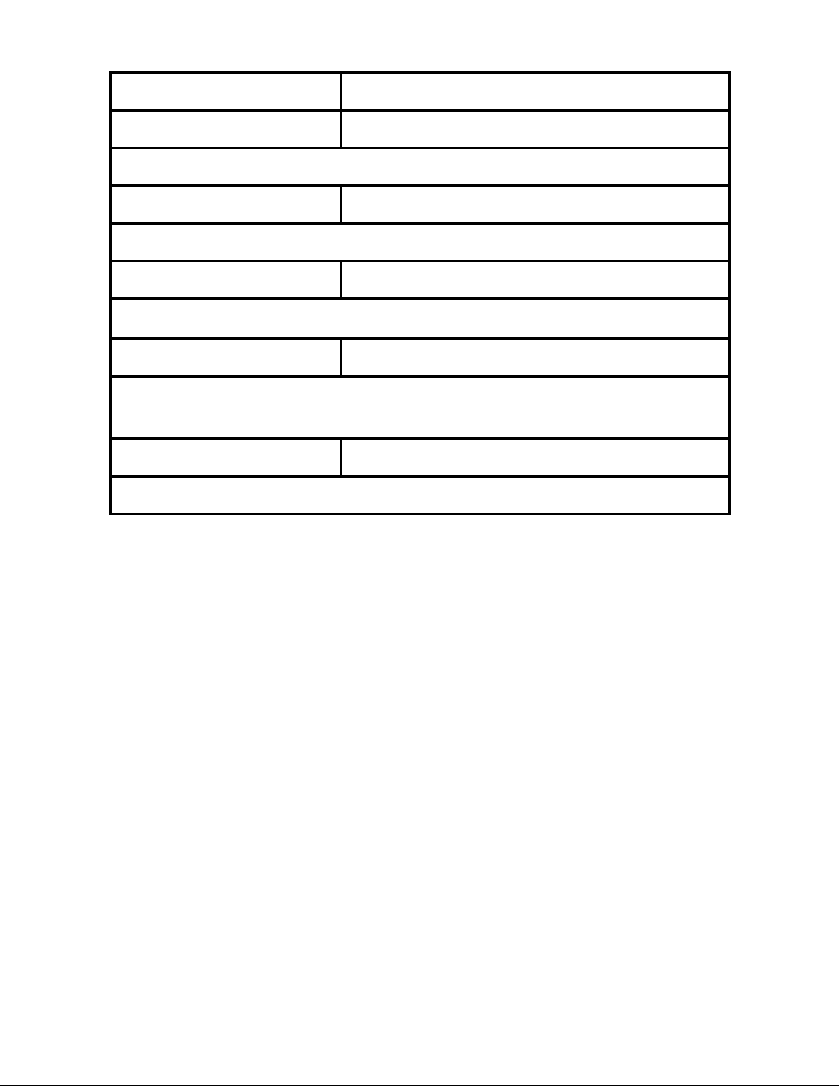
Optional Pressure Modules
Sensor Code Application
DNxxxx Differential, Non-isolated
0 to 0010*, 0028, 0200, 0415, 2000” H2O
DIxxxx Differential, Isolated
0 to 0001, 0005, 0015, 0030, 0100, 0300, 0500 PSID
GIxxxx Gauge, Isolated
0 to 0015, 0030, 0050, 0100, 0300, 0500, 1000, 3000 PSIG
CIxxxx Compound, Isolated
-14.7 to +0015, 0030, 0050, 0100, 0300, 0500, 1000, 3000
PSIG
AIxxxx Absolute, Isolated
0 to 0017, 0038, 0100, 1000 PSIA
Media Compatibility
Non-isolated DN sensors: clean, dry, non-corrosive,
non-condensing gases only
Isolated DI sensors: any media compatible with 316L SS &
Viton®
Isolated GI, CI & AI sensors: any media compatible with 316L SS
Pressure Module Accuracy
±0.025% of full scale including all effects of linearity,
repeatability and hysteresis from -20° to +50°C (-4° to +122°F)
* The DN0010 sensor accuracy is ±0.050% of full scale
32 Engineering Units:
PSI • inches, feet, mm, cm and meter of H2O @ 4°C, 20°C & 60°F
inches, meter, cm and mm of Hg @ 0°C
torr • kg/cm2 • kg/m2 • Pa • hPa • kPa • MPa • Bar • mBar
ATM • oz/in2 • lb/ft2
Page 39
Find Quality Products Online at: [email protected]
www.GlobalTestSupply.com
Page 42

General
Specifications
Operating Temp Range
-20 to 60 °C (-5 to 140 °F)
Storage Temp Range -30 to 60 °C (-22 to 140 °F)
Temperature effect ≤ ± 0.01 %/°C of Full Scale; Cold
Junction Sensor ≤ ±25 ppm/°C
Relative Humidity
Range
10 % ≤RH ≤90 % (0 to 35 °C),
Non-condensing
10 % ≤RH≤ 70 % (35 to 60 °C),
Non-condensing
Isolation: Voltage
60V rms between all mA functions/Read
V DC and Source V DC/thermocouple/
RTD/Ohms//Frequency/Pressure
Common Mode
Normal Mode Rejection
Noise
50/60 Hz, 100 dB
50/60 Hz, 50 dB
≤ ± ½ Least Significant Digit from 0.1 to 10 Hz
Size
Weight
5.63x3.00x1.60” 143x76x41mm (LxWxH)
12.1 ounces, 0.34 kg with boot & batteries
Batteries Four “AA” Alkaline 1.5V (LR6)
Battery life
Read Functions: ≥ 20 hrs; Pressure ≥ 7 hrs
Source mA: ≥ 14 hours @ 12 mA into 250Ω
Pwr/Meas mA: ≥ 12 hours at 20 mA
Source V, Ω, T/C, RTD & Hz:
≥ 20 hours
Low Battery Low battery indication with nominal 1
hour of operation left
Protection against
misconnection
Over-voltage protection to 60 vrms
(rated for 30 seconds)
Red LED indicates OVERLOAD or out
of range conditions
Display
High contrast graphic liquid crystal display,
0.315” (8.0 mm) high digits, backlighting
Page 40
Find Quality Products Online at: [email protected]
www.GlobalTestSupply.com
Page 43

Read mA
Specifications
Ranges and Resolution
0.000 to 24.000 mA or -25.00 to 125.00%
of 4-20 mA
Accuracy ≤ ± (0.02 % of Reading + 0.003 mA)
Voltage burden ≤ 2V at 24 mA
Overload/Current
25 mA nominal
limit protection
Source mA / Power & Measure Two Wire Transmitters
Ranges and Resolution
Same as Read mA
Accuracy ≤ ± (0.02 % of Reading + 0.003 mA)
Loop compliance voltage
≥ 24 DCV @ 20.00mA
Loop drive capability 1200 Ω at 20 mA for 15 hours nominal;
950 Ω with Hart Resistor enabled
mA 2-Wire Transmitter Simulation
Accuracy Same as Source/Power & Measure
Voltage burden ≤ 2V at 20 mA
Overload/Current limit 24 mA nominal
Loop voltage limits 2 to 60 VDC (fuse-less protected)
DC Voltage Read
Range and Resolution
±99.999 mV, ±999.99mV, 0 to 10.250 V, 0.00
to 60.00 V DC
Accuracy
≤ ± (0.02 % of Reading + 0.01% Full Scale)
Input resistance ≥ 1 MΩ
Page 41
Find Quality Products Online at: [email protected]
www.GlobalTestSupply.com
Page 44

Source V dc
Specifications
Ranges and Resolution
-20.000 to 99.999 mV, -500.00 to 999.99 mV,
0.000 to 10.250V
Accuracy
Source Current
≤ ± (0.02 % of Reading + 0.01% Full Scale)
≥ 20 mA
Sink Current > 16 mA
Output Impedance < 1 Ohm
Short Circuit Duration Infinite
pH Source
Range and Resolution
Accuracy in mV
-414.00 to +414.00 pH
≤ ± (0.02 % of Reading in mV + 0.1 mV)
Accuracy in pH ≤ ± 0.003 pH @ 25°C
Thermocouple Source
Accuracy ≤ ± (0.02 % of Reading + 0.01 mV)
Cold Junction Compensation
± 0.05°C; Thermistor traceable to
NIST for 11 years
Output Impedance < 1 Ohm
Source Current > 20 mA (drives 80 mV into 10 Ohms)
Thermocouple Read
Accuracy & Cold
Same as Thermocouple Source
Junction Compensation
Input Impedance
Open TC Threshold;
Pulse
> 1 Megohms
10K Ohms; <5 µamp pulse for 300
milliseconds (nominal)
Page 42
Find Quality Products Online at: [email protected]
www.GlobalTestSupply.com
Page 45
Specifications
RTD, OHMS and Continuity Read
Resistance Ranges 0.00 to 401.00, 0.0 to 4010.0 Ohms
Accuracy ±(0.025% of Reading + 0.075 Ohms)
Excitation Current
1.0 mA to 401 Ohms, 0.5 mA to 4010
Ohms (nominal)
Continuity 0.0 to 401.0 Ohms; Beeps from 0.0 to
100.0 Ohms
RTD and OHMS Source
3 Wire & 4 Wire
Accuracy
F r o m 1 t o 1 0 . 2 m A
±(0.025% of Full Scale + 0.075 Ohms)
External Excitation Current
B e l o w 1 m A o f E x t e r n a l
Excitation Current
±(0.025% of Full Scale+0.075 Ohms +
0.025 mV
)
mA Excitation Current
2 Wire Accuracy
Add 0.1 Ohm to specifications listed above
Resistance Ranges 0.00 to 401.00, 0.0 to 4010.0 Ohms
Allowable Excitation
Current Range
<401 Ohm:10.2 mA max; steady or pulsed/
intermittent
401 to 4000 Ohms: 1 mA max; steady or
pulsed/intermittent
Pulsed Excitation
DC to 0.01 second pulse width
Current Compatibility
Page 43
Find Quality Products Online at: [email protected]
www.GlobalTestSupply.com
Page 46

Specifications
Frequency Source
Ranges 1 to 2000 CPM, 0.01 to 999.99 Hz, 0.1
to 9999.9 Hz, 0.001 to 20.000 kHz
Accuracy
Output Waveform
± (0.02 % of Reading + 0.01% Full Scale)
Square Wave, Zero Crossing -1.0 to +5 V
peak-to-peak ±10%
Risetime (10 to 90% of
< 10 microseconds
amplitude)
Output Impedance < 1 Ohm
Source Current > 1 mA rms at 20 kHz
Short Circuit Duration Infinite
Optical Coupling Green LED (HZ SYNC) flashes at
output frequency
Frequency Read
Ranges & Accuracy Same as Frequency Source
Accuracy
± (0.02 % of Reading + 0.01% Full Scale)
Trigger Level 1 V rms, dc coupled
Input Impedance > 1 Meg Ohm + 60 pF
Page 44
Find Quality Products Online at: [email protected]
www.GlobalTestSupply.com
Page 47
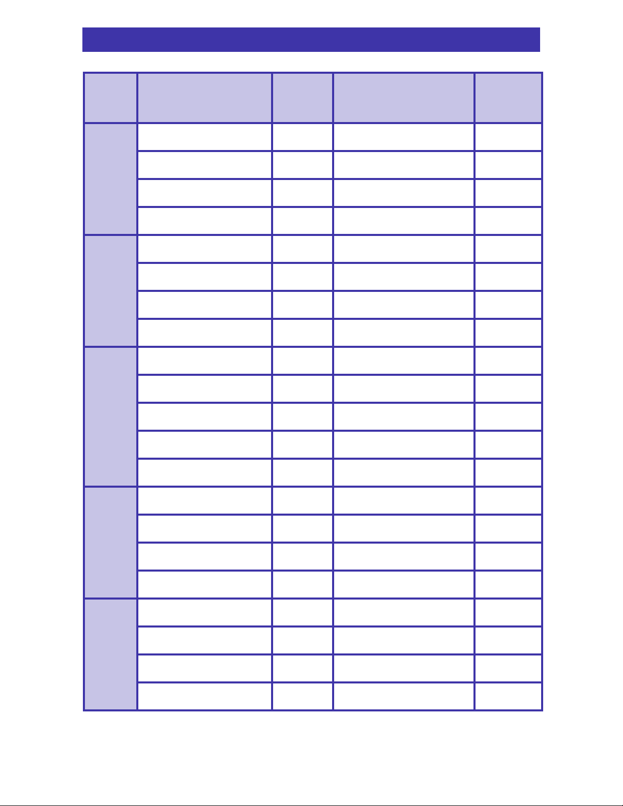
Thermocouple Ranges & Accuracies
Based on ≤ ± (0.02 % of Reading + 0.01 mV)
T/C Degrees C
Range
°C Degrees F
Range
°F
J -200.0 to -50.0 ±0.5° -328.0 to -58.0 ±1.0°
-50.0 to 300.0 ±0.2° -58.0 to 572.0 ±0.4°
300.0 to 900.0 ±0.3° 572.0 to 1652.0 ±0.6°
900.0 to 1200.0 ±0.4° 1652.0 to 2192.0 ±0.8°
K -230.0 to -50.0 ±1.2° -382.0 to -58.0 ±2.2°
-50.0 to 550.0 ±0.3° -58.0 to 1022.0 ±0.6°
550.0 to 1000.0 ±0.5° 1022.0 to 1832.0 ±0.8°
1000.0 to 1371.1 ±0.6° 1832.0 to 2500.0 ±1.1°
T -260.0 to -230.0 ±2.9° -436.0 to -382.0 ±5.2°
-230.0 to -210.0 ±1.0° -382.0 to -346.0 ±1.9°
-210.0 to -50.0 ±0.8° -346.0 to -58.0 ±1.4°
-58.0 to 50.0 ±0.3° -58.0 to 122.0 ±0.6°
50.0 to 400.0 ±0.2° 122.0 to 752.0 ±0.4°
E -240.0 to -200.0 ±0.9° -400.0 to -328.0 ±1.7°
-200.0 to 0.0 ±0.5° -328.0 to 32.0 ±0.8°
0.0 to 350.0 ±0.2° 32.0 to 662.0 ±0.3°
350.0 to 1000.0 ±0.3° 662.0 to 1832.0 ±0.6°
R -18.3 to 100.0 ±2.1° -1.0 to 212.0 ±3.8°
100.0 to 500.0 ±1.3° 212.0 to 932.0 ±2.4°
500.0 to 1400.0 ±1.0° 932.0 to 2552.0 ±1.8°
1400.0 to 1767.8 ±1.2° 2552.0 to 3214.0 ±2.0°
Note: Doesn’t include cold junction error of ±0.05°C
Page 45
Find Quality Products Online at: [email protected]
www.GlobalTestSupply.com
Page 48
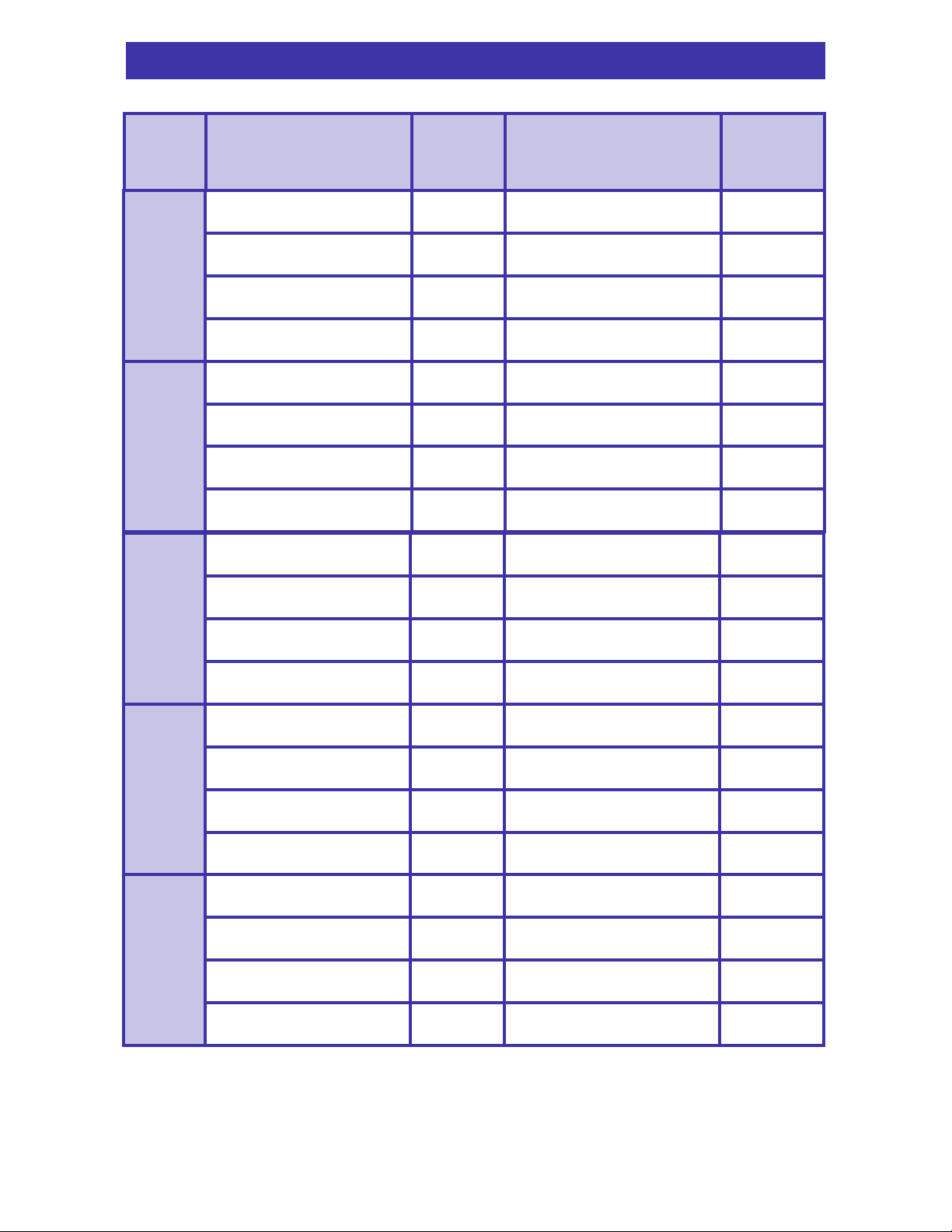
Thermocouple Ranges & Accuracies
Based on ≤ ± (0.02 % of Reading + 0.01 mV)
T/C Degrees C
Range
°C Degrees F
Range
°F
S -18.3 to 100.0 ±2.0° -1.0 to 212.0 ±3.7°
100.0 to 350.0 ±1.4° 212.0 to 662.0 ±2.5°
350.0 to 1600.0 ±1.1° 662.0 to 2912.0 ±2.0°
1600.0 to 1767.8 ±1.3° 2912.0 to 3214.0 ±2.4°
B 315.6 to 600.0 ±3.2° 600.0 to 1122.0 ±5.7°
600.0 to 850.0 ±1.7° 1122.0 to 1562.0 ±3.1°
850.0 to 1100.0 ±1.3° 1562.0 to 2012.0 ±2.4°
1100.0 to 1820.0 ±1.1° 2012.0 to 3308.0 ±2.0°
N -230.0 to -150.0 ±1.9° -382.0 to -238.0 ±3.4°
G
(W)
C
(W5)
-150.0 to -50.0 ±0.7° -238.0 to -58.0 ±1.2°
-50.0 to 950.0 ±0.4° -58.0 to 1742.0 ±0.8°
950.0 to 1300.0 ±0.5° 1742.0 to 2372.0 ±1.0°
100.0 to 350.0 ±1.7° 212.0 to 662.0 ±3.0°
350.0 to 1700.0 ±0.8° 662.0 to 3092.0 ±1.5°
1700.0 to 2000.0 ±1.0° 3092.0 to 3632.0 ±1.8°
2000.0 to 2320.0 ±1.1° 3632.0 to 4208.0 ±2.1°
-1.1 to 100.0 ±0.8° 30.1 to 212.0 ±1.4°
100.0 to 1000.0 ±0.7° 212.0 to 1832.0 ±1.3°
1000.0 to 1750.0 ±1.2° 1832.0 to 3182.0 ±2.1°
1750.0 to 2320.0 ±2.0° 3182.0 to 4208.0 ±3.5°
Note: Doesn’t include cold junction error of ±0.05°C
Page 46
Find Quality Products Online at: [email protected]
www.GlobalTestSupply.com
Page 49
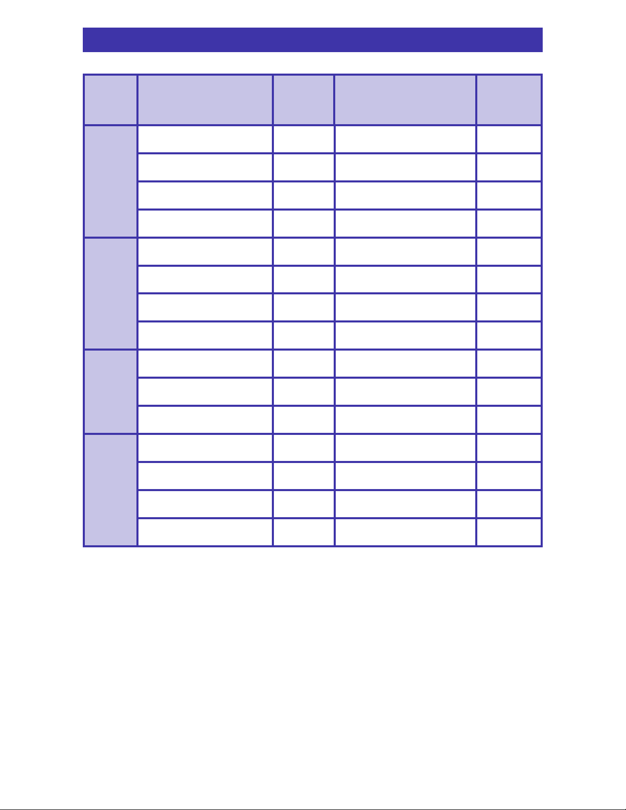
Thermocouple Ranges & Accuracies
Based on ≤ ± (0.02 % of Reading + 0.01 mV)
T/C Degrees C
Range
°C Degrees F
Range
°F
D -1.1 to 150.0 ±1.0° 30.1 to 302.0 ±1.8°
150.0 to 1100.0 ±0.7° 302.0 to 2012.0 ±1.3°
1100.0 to 1750.0 ±1.0° 2012.0 to 3182.0 ±1.8°
1750.0 to 2320.0 ±2.0° 3182.0 to 4208.0 ±3.6°
P 0.0 to 600.0 ±0.3° 32.0 to 1112.0 ±0.6°
600.0 to 900.0 ±0.4° 1112.0 to 1652.0 ±0.8°
900.0 to 1200.0 ±0.6° 1652.0 to 2192.0 ±1.1°
1200.0 to 1395.0 ±0.7° 2192.0 to 2543.0 ±1.2°
L
-200.0 to -50.0 ±0.4° -328.0 to -58.0 ±0.7°
J-DIN
-50.0 to 300.0 ±0.2° -58.0 to 572.0 ±0.4°
300.0 to 900.0 ±0.3° 572.0 to 1652.0 ±0.5°
U
T-DIN
-200.0 to -50.0 ±0.6° -328.0 to -58.0 ±1.1°
-50.0 to 50.0 ±0.3° -58.0 to 122.0 ±0.5°
50.0 to 550.0 ±0.2° 122.0 to 1022.0 ±0.4°
550.0 to 600.0 ±0.3° 1022.0 to 1112.0 ±0.5°
Note: Doesn’t include cold junction error of ±0.05°C
Page 47
Find Quality Products Online at: [email protected]
www.GlobalTestSupply.com
Page 50

RTD Ranges & Accuracies
RTD Accuracy Based on
RTD
Degrees C
Type
Pt 100 Ohm
DIN/IEC/JIS 1989
1.3850 (ITS-90)
-200.0 to 0.0
0.0 to 340.0
340.0 to 640.0
640.0 to 850.0
Pt 100 Ohm
(Burns)
1.3902
-200.0 to 10.0
10.0 to 350.0
350.0 to 650.0
650.0 to 850.0
Pt 100 Ohm
(Old JIS 1981)
1.3916
-200.0 to 20.0
20.0 to 360.0
360.0 to 650.0
±(0.025% of Reading in Ohms + 0.075 Ohms)
Degrees F
Range
°C
±0.2°
±0.3°
±0.4°
±0.5°
±0.2°
±0.3°
±0.4°
±0.5°
±0.2°
±0.3°
±0.4°
Range
-328.0 to 32.0
248.0 to 644.0
644.0 to 1184.0
1184.0 to 1562.0
-328.0 to 50.0
50.0 to 662.0
662.0 to 1202.0
1202.0 to 1562.0
-328.0 to 68.0
68.0 to 680.0
680.0 to 1202.0
°F
±0.4°
±0.6°
±0.8°
±1.0°
±0.4°
±0.6°
±0.8°
±0.9°
±0.4°
±0.6°
±0.8°
Pt 100 Ohm
(US Lab)
1.3926
Pt 1000 Ohm
DIN/IEC/JIS 1989
1.3850
Copper 10 Ohm
1.4274 (Minco)
Copper 50
1.4280
Ni 120 Ohm
1.6720 (Pure)
650.0 to 850.0
-200.0 to 20.0
20.0 to 360.0
360.0 to 660.0
660.0 to 850.0
-200.0 to 0.0
0.0 to 340.0
340.0 to 640.0
640.0 to 850.0
-200.0 to 260.0
-50.0 to 150.0
-80.0 to 260.0
±0.5°
±0.2°
±0.3°
±0.4°
±0.5°
±0.2°
±0.3°
±0.4°
±0.5°
±2.0°
±0.4°
±0.1°
1202.0 to 1562.0
-328.0 to 68.0
68.0 to 680.0
680.0 to 1220.0
1220.0 to 1562.0
-328.0 to 32.0
248.0 to 644.0
644.0 to 1184.0
1184.0 to 1562.0
-328.0 to 500.0
-58.0 to 302.0
-112.0 to 500.0
±0.9°
±0.4°
±0.6°
±0.8°
±0.9°
±0.4°
±0.6°
±0.8°
±1.0°
±3.6°
±0.8°
±0.3°
Ni 110 Ohm
-100.0 to 260.0
±0.2°
-148.0 to 500.0
±0.4°
Bristol 7 NA 1.5801
Page 48
Find Quality Products Online at: [email protected]
www.GlobalTestSupply.com
Page 51

Standard Warranty
Our equipment is warranted against defective material and
workmanship (excluding batteries) for a period of three years
from the date of shipment. Claims under warranty can be made
by returning the equipment prepaid to our factory. The equipment
will be repaired, replaced or adjusted at our option. The liability
of Practical Instrument Electronics (PIE) is restricted to that
given under our warranty. No responsibility is accepted for
damage, loss or other expense incurred through sale or use of
our equipment. Under no condition shall Practical Instrument
Electronics, Inc. be liable for any special, incidental or
consequential damage.
Pressure sensors that have been damaged by over
pressurization or contaminated by process chemicals are not
covered by our warranty. Pneumatic pumps that are contaminated
with process chemicals are also not covered by our warranty.
Optional Repair/Replacement Warranty
Under our Repair/Replacement Warranty (RP-WAR-B), our
equipment is warranted against ANY damage or malfunction
that may cause the unit to fail for a period of three (3) years from
the date of shipment.
This warranty is limited to one complete replacement against
any damage or malfunction during the warranty period. If
replaced, the new calibrator will carry our Standard Warranty for
the remainder of the three (3) years or a minimum of one (1)
year from the date of shipment.
Additional Information
PIE Calibrators are manufactured in the USA.
This product is
calibrated on equipment traceable to NIST and includes a
Certificate of Calibration. Test Data is available for an additional
charge.
Practical Instrument Electronics recommends a calibration
interval of one year. Contact your local representative for
recalibration and repair services.
Page 49
Find Quality Products Online at: [email protected]
www.GlobalTestSupply.com
Page 52

 Loading...