

Page 1

DEUTSCH · ENGLISH · FRANÇAIS
USER
GUIDE
PIEGA CONNECT
Premium Wireless by PIEGA
EXPECT MORE
Page 2

OPERATING INSTRUCTIONS
Premium Wireless by PIEGA
Page 3
CONTENTS
Important Safety Instructions ............................................. 4
Operating elements of the PIEGA connect ........................ 6
Overview ........................................................................... 6
Description of the operating elements of the
PIEGA connect .................................................................... 8
Volume
Input
Determination of input source and priority
Group
Wireless
Output
Service
Power
Volume control
Bluetooth pairing
Operating elements of the PIEGA speaker ...................... 17
Overview ......................................................................... 17
Description of the operating elements of
the PIEGA speaker ............................................................ 18
Group
Speaker position
Input
Service
Supply
Installation instructions ...................................................... 22
Wireless ........................................................................... 24
1) Connection between playback device
and PIEGA connect ........................................................ 24
1
....................................................................... 8
2
3 4 5
6
7
8
.................................................................... 13
9
...................................................................... 14
10
..................................................................... 14
11
....................................................................... 15
1
2
5
......................................................................... 21
6
..................................................................... 21
7
8
.................................................... 10
5
................. 11
................................................................ 13
12
.......................................................... 15
13
....................................................... 16
................................................................ 18
3
4
................................................ 18
............................................................... 21
2) Operating elements settings ............................................. 25
3) Power supply to the PIEGA connect ........................... 27
4) Unpack and set up the speaker ................................. 27
5) Power supply to the speaker ...................................... 27
6) Speaker settings ........................................................ 27
7 ) Connection of Bluetooth devices (optional) ................ 27
8) Your system is ready .................................................. 27
Connection of the subwoofer (peripheral equipment) ........ 28
1) Introduction ................................................................ 28
2) Connecting the PIEGA connect to a subwoofer .......... 28
Using several PIEGA connect systems ............................. 29
As active speaker ............................................................ 31
1) Playback device ......................................................... 31
2) Unpack and set up the speaker ................................. 31
3) Speaker settings ........................................................ 31
4) Connecting the speaker to the playback device ......... 32
5) Power supply to the speaker ...................................... 32
Operation ........................................................................... 33
General ............................................................................ 33
Bluetooth function and priority .......................................... 33
Overview of the status displays ........................................ 35
Technical data .................................................................... 36
PIEGA connect ................................................................ 36
PIEGA wireless speaker ................................................... 37
FAQs (frequently asked questions) ................................... 38
Declaration of Conformity ................................................. 40
User Manual // 3
Page 4

IMPORTANT SAFETY INSTRUCTIONS
1. Read these instructions.
2. Keep these instructions.
3. Observe all warnings.
4. Follow all instructions.
5. Do not use this apparatus near water.
6. Clean only with dry soft cloth.
7. Do not install near any heat sources such as radiators, heat registers, stoves, or other devices that produce heat.
8. Ensure that the power cable is not stepped on or pinched, particularly at plugs, convenience receptacles, and wherever cables exit apparatuses.
9. Only use attachments/accessories that are approved by the manufacturer.
10. Do nor circumvent the safety purpose of the polarized type plug. If the provided plug does not fit into your outlet, consult an electrician for replacement of the
obsolete outlet.
11. Unplug this apparatus during lightning storms or when unused for long periods of time.
12. Only entrust qualified service personnel with servicing activities. Servicing is required when the apparatus has been damaged in any way, for example if the
power-supply cable or plug is damaged, liquid has been spilled, objects have fallen into the apparatus, the apparatus has been exposed to rain or moisture, does
not operate normally, or has been dropped.
13. The mains plug should be easily accessible to disconnect the equipment.
14. Warning: To reduce the risk of fire and electric shock, do not expose this apparatus to rain or moisture.
15. Do not expose the apparatus to dripping or splashing and do not place objects filled with liquids, such as vases, on the apparatus.
16. 150 mm minimum distances around the apparatus for sufficient ventilation.
17. The ventilation should not be impeded by covering the ventilation openings with items. Such as newspapers, table-cooths, curtains, etc.
18. No naked flame source, such as lighted candles, should be placed on the apparatus.
19. The use of apparatus in tropical and moderate climates.
4 // User Manual
Page 5
WARNING
The symbol is intended to alert the user to the presence of uninsulated dangerous voltage
within the product’s enclosure that may be of sufficient magnitude to constitute risk of fire and
electric shock.
PIEGA wireless speakers RISK OF ELECTRIC SHOCK! DO NOT OPEN! If the speakers are connected to the mains voltage, a dangerous electrical voltage is present
inside the speakers
- Use the supplied power cable to connect the speakers to the mains voltage. Make sure that the power supply cable is not damaged; replace it with a new
one if it has been damaged.
- To reduce the risk of electric shock, do not remove the back panel and never open the speaker housing. Do not expose the speakers to rain or moisture. No
inside parts can be serviced by users. Refer servicing to qualified personnel.
- Do not operate defective speakers and disconnect defective speakers from the mains voltage. Please contact your PIEGA distributor if you experience any
problems.
Never place a speaker set in an unstable location. A speaker set may fall, causing serious personal injury or death. Many injuries, particularly to children, can be
avoided by taking simple precautions such as:
- Using cabinets or stands recommended by the manufacturer of the speaker set.
- Only using furniture that can safely support the speaker set.
- Ensuring the speaker set is not overhanging the edge of the supporting furniture.
- Not placing the speaker set on tall furniture (for example, cupboards or bookcases) without anchoring both the furniture and the speaker set to a suitable
support.
- Not placing the speaker set on cloth or other materials that may be located between the speaker set and supporting furniture.
- Educating children about the dangers of climbing on furniture to reach the speaker set or its controls.
If your existing speaker set is being retained and relocated, the same considerations as above should be applied.
The symbol is intended to alert the user to the presence of important operating and maintenance instructions in the literature accompanying this product.
UNPACKING
After unpacking, make sure the system is complete and check the device and all accessories for transport damage. Transport damage may be expected if the pack-
aging is already showing severe wear. Do not attempt to start up a damaged device. If the contents are incomplete or damaged, please contact your PIEGA distributor.
PACKAGING MATERIAL
The packaging has been designed to be used again, as long as it has not been damaged during transport. Keep the packaging and use the original packaging for all
further transport.
User Manual // 5
Page 6
OPERATING ELEMENTS OF THE
coax
Volume
fix
var
analog
optical
Group
white
blue
a
b
analog
red c*
service
POWER
* c no BT
RLR
L
INPUT
Music Source
OUTPUT
Speaker / Subwoofer / Amp
Wireless
frequency
DC 5V =
1A
1 2 3 4 7 8 9 11
5 6 10
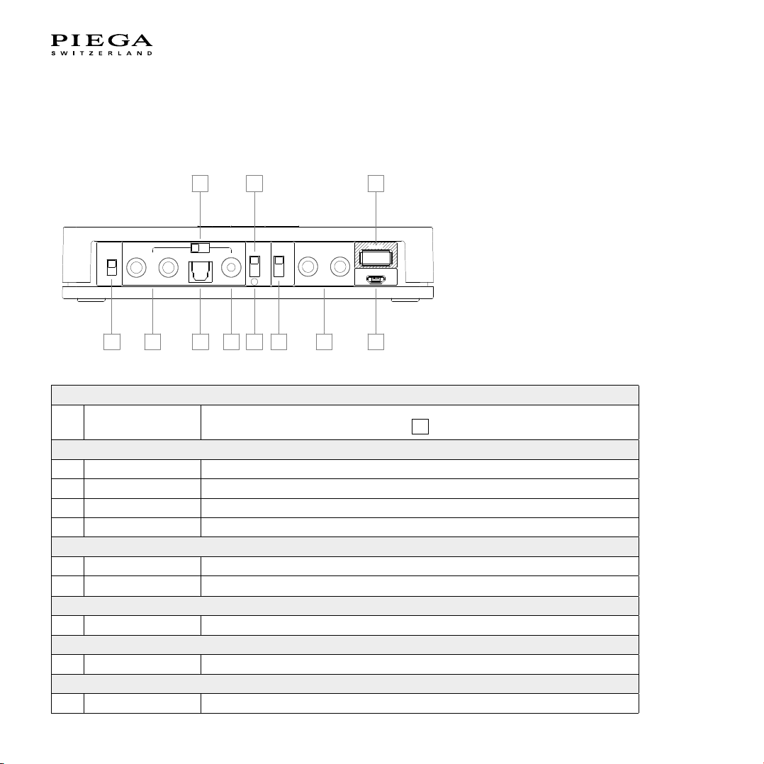
PIEGA CONNECT
Overview
Volume
1 fix / var
Input
2 Analog Input terminal for analog signal sources
3 Optical Optical/digital input
4 Coax Coaxial/digital input
5 Select Determination of input source (analog / optical / coax) and priority
Group
6 Select Group switch (white 48kHz / blue 48kHz / red 96kHz)
7 LED display Group status display (white/blue/red)
Wireless
8 Select Wireless frequency selector switch (2.4 / 5.2 / 5.8 GHz)
Output
9 Analog Analog regulated output
Service
10 USB Service connection
Fixed (maximum) volume
Variable volume. Adjust using buttons +/-
12
6 // User Manual
Page 7
Power
12
13
14
11 Micro USB Power supply 5 V DC 1A
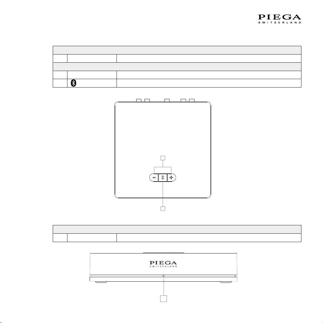
Top view
12 - / + Volume control / LED display via buttons
13
Bluetooth pairing
Volume
14 LED display Display of connection status and group allocation
User Manual // 7
Page 8

DESCRIPTION OF THE OPERATING
ELEMENTS OF THE PIEGA CONNECT
Volume
The “Volume” setting is used to activate or deactivate the volume control
fix = volume control deactivated. PIEGA connect uses the maximum volume.
This setting is suitable for use with playback devices with integrated volume control.
The following are examples of possible regulated sources:
- Multiroom systems – the volume is controlled via the respective app.
- Connection via Bluetooth – the volume is controlled by the corresponding Bluetooth device.
- Network player with integrated volume control
- Television
var = volume control activated
This setting is suitable for use with unregulated playback devices.
Unregulated playback devices do not offer an option to adjust the volume using the
playback device (signal output with maximum volume).
A few examples of possible unregulated sources are:
- CD player
- Record player (please note that depending on the model of the record player,
an additional phono preamp may be required.)
1
12
NOTE: Some playback devices can activate and deactivate the volume control independently.
8 // User Manual
Page 9

Vol ume
fix
var
Music Source
Digital
PIEGA connect
Wirel ess
Module
Bluetooth
Device
OR
fix:
Bypasses Volume Setting
var:
passes Volume Setting
min
max
12
1
User Manual // 9
Page 10
Input
coax
Volume
fix
var
analog
optical
Group
white
blue
a
b
analog
red c*
service
POWER
* c no BT
RLR
L
INPUT
Music Source
OUTPUT
Speaker / Subwoofer / Amp
Wireless
frequency
DC 5V =
1A
2 34
5
2 3 4 5
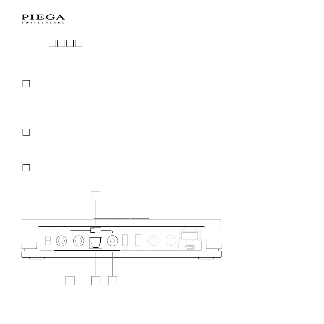
Connecting your music source / your playback device – PIEGA connect offers three different connection options for external
playback devices.
Input Terminal Signal Description
2
Analog RCA Analog Possible analog input sources / devices:
- Record player
- Headphone output / TV
- CD player
- Multiroom system
- Network player
3
Optical Toslink S/PDIF Possible optical input sources / devices:
- Multiroom systems often offer optical outputs
Digital - TV
- Network player
4
Coax RCA S/PDIF Possible coaxial input sources / devices:
- Multiroom systems often offer coaxial outputs
Digital - Network player
10 // User Manual
Page 11
Determination of input source and priority
The PIEGA connect has several options for determining the type of input source (analog, optical, coaxial). The input sources can be preset and prioritized for the desired application (e.g. setup with TV, subwoofer, network player, turntable, etc.).
However, bluetooth has always the highest priority and therefore overrides all other input sources. Consequently, allowing an
automatic switch from the input source to bluetooth.
5
Analog Optical Coax
1 2 3
3 1 2
3 2 1
3
PIEGA recommends using a digital input wherever possible (
Using a digital input eliminates the need for a conversion (analog to digital) in the signal chain, leading to a better sound result.
or 4 ).
User Manual // 11
Page 12
ANALOG SOURCE
Wireless
Module
ADC
Analog - Digital
Digital Digital
Music Source
Analog
Analog
Analog Digital Analog
Wireless
Module
ADC
Analog - Digital
Digital Digital
Music Source
Analog
Analog
Analog Digital Analog
Wireless
Module
Digital
Digital Analog
Music Source
Digital
Digital
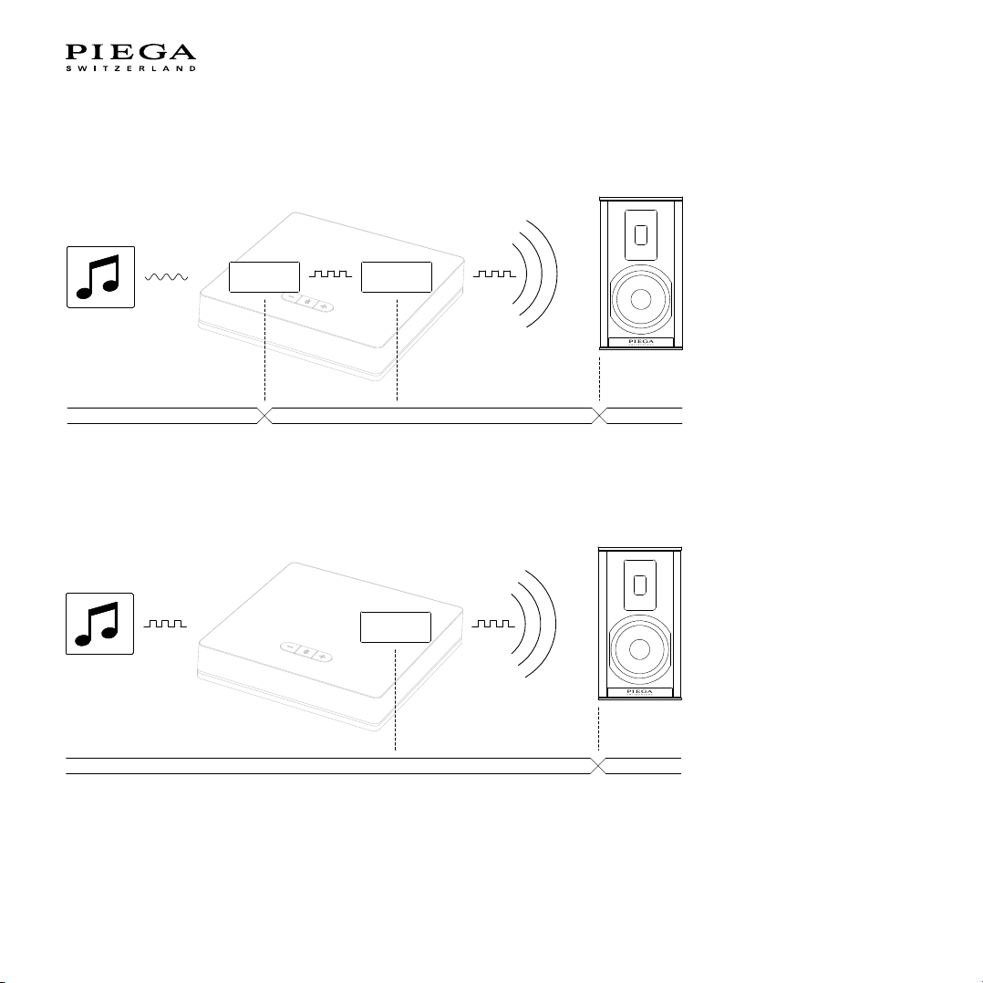
If the music is in digital form (CD, streaming, etc.), it is converted into an analog signal by the playback device. However, PIEGA
connect only processes digital signals internally. As a result, the analog signal must be re-converted into a digital signal.
DIGITAL SOURCE
Continuous digital signal processing
NOTE: In some playback devices such as televisions, the volume control of the playback device only functions via the analog
connection. In this case, please observe the operating instructions for your playback device.
12 // User Manual
Page 13

Group
The “Group” function is only required when using several PIEGA wireless systems (more than one PIEGA connect). The music
signal is only sent to speakers within the same group. This ensures the smooth operation of up to three independent PIEGA
wireless systems in one room/flat/house.
6 7
GROUP WIRELESS DATA TRANSMISSION
white 24 Bit / 48 kHz
blue 24 Bit / 48 kHz
red 24 Bit / 96 kHz
The group display 7shows the selected group colour and the connection status. This must correspond to the speaker in
order to operate.
NOTE: We deliver our speakers and PIEGA connect with the group setting “white”. When using a PIEGA wireless system, we
recommend leaving the group setting as “white”.
Wireless
The “Wireless” function is only required to eliminate any possible disturbances. This may include no connection or a lapse/
stuttering of the music playback. The PIEGA wireless system sets up an independent wireless network to transfer data from the
PIEGA connect to PIEGA speakers. This means that the system is not reliant on your home WLAN. This ensures a continuous
transfer of data.
Should the transmission be impaired by a neighbouring wireless network, the carrier frequency of the wireless signal can be
adjusted.
Such an impairment can be determined as follows:
Your system is running smoothly, provided no clearly audible faults (interruptions, stuttering, etc.) can be made out in the music
playback, or your speakers are unable to connect to the PIEGA connect.
The following carrier frequencies are supported:
A: 5.2 GHz PIEGA recommends using this frequency whenever possible.
B: 5.8 GHz
C: 2.4 GHz (also used by Bluetooth, which may cause faults when it is combined with the wireless system)
8
User Manual // 13
Page 14

coax
Volume
fix
var
analog
optical
Group
white
blue
a
b
analog
red c*
service
POWER
* c no BT
RLR
L
INPUT
Music Source
OUTPUT
Speaker / Subwoofer / Amp
Wireless
frequency
DC 5V =
1A
Music Source
OR OR OR
Amplifier
Subwoofer
OR
9
Output
9
A subwoofer or an additional active speaker can be added using the Analog output.
PIEGA connect offers an analog output in addition to the wireless music transfer.
The analog signal corresponds to the wireless signal, i.e. any volume regulation is also applied to the analog output.
Possible setup with subwoofer OR active speakers OR existing stereo system.
Service
Any required software updates can be loaded via the USB service connection.
You can find the operating software on our website www.piega.ch.
10
14 // User Manual
Page 15

Volu me
fix
var
Music Source
Digital
PIEGA connect
Wireles s
Module
Bluetooth
Device
OR
fix:
Bypasses Volume Setting
var:
passes Volume Setting
min
max
12
1
Power
GOLDEN PROFIT
ELECTRONICS LTD.
外壳
材料
A4
图寸
型号
mm
批准
设计
校对
设计日期
单位 比例
尺寸公差
产品名称
图号
陈健生
版本号
正
极
负
极
GOLDEN PROFIT
ELECTRONICS LTD.
外壳
材料
A4
图寸
型号
mm
批准
设计
校对
设计日期
单位 比例
尺寸公差
产品名称
图号
陈健生
版本号
李增灿
余明昭
11
Please use the adapter and micro USB cable included in the delivery.
Alternatively, you can use a standard commercial USB adapter which meets the following specifications:
- 5 V DC
- 1 A
Volume control
12
Setting the volume on the PIEGA connect (top side of the device) – the volume control
music signal as well as the analog output 9.
NOTE: For more information regarding volume, please go to point ”Volume”, page 8.
12
affects the wireless
User Manual // 15
Page 16

Bluetooth pairing
13
Mobile
Bluetooth
Settings
PAIR
The Bluetooth pairing establishes the connection between the PIEGA speaker system and your smartphone, tablet, etc. and
enables the radio link. You must carry out the pairing process between a device and the PIEGA connect in order to establish
a BLUETOOTH connection for the first time.
Upon pressing the pairing button 13, the PIEGA connect will be recognised by your BLUETOOTH device, allowing a connection to be established.
Flashing of the pairing button 13 signals pairing mode.
13
NOTE: The PIEGA connect supports a simultaneous connection of up to two Bluetooth devices.
WARNING: If two Bluetooth devices are already connected to the PIEGA connect, the pairing function can no longer be
carried out. In order to enable pairing, the Bluetooth connection with one of the two devices must be disconnected.
16 // User Manual
Page 17

OPERATING ELEMENTS OF THE
Group
white
blue
red
Speaker Position
service
INPUT
analog
neutral
wall
corner
POWER
AC 100-120/220-240V 50/60Hz 250W
left
mono
right
1
3
5
6
8
2
4
7
PIEGA SPEAKER
Overview
Group
1 Select Group switch
2 Display Group status display (white/blue/red)
Speaker position
Setup Adjusting the speaker with regard to the setup
3
Channel
4
selection switch
Input
5 Analog input Analog input
Service
6 USB Service connection
Power
7 LED display Operating status display
8 Power socket Supply AC 100 – 120 / 220 – 240 V. 50 / 60 Hz.
location (neutral/wall/corner)
Allocating the position of the speaker
(left/mono/right)
User Manual // 17
Page 18

DESCRIPTION OF THE OPERATING
Speaker
Speaker
0.5 m and more
Wal l
ELEMENTS OF THE PIEGA SPEAKER
Group
This function is only required when using several PIEGA wireless systems (more than one PIEGA connect).
Ensure that the same group is selected as with your PIEGA connect.
The music signal is only sent to speakers within the same group. This ensures the smooth operation of up to three independent
PIEGA wireless systems in one room/flat/house.
The group display 2 shows the selected group colour and the connection status. This must correspond to the respective
PIEGA connect.
You can find additional information about the connection status in overview of the status displays.
NOTE: More than two speakers can be operated simultaneously in the same group. Our speakers and the PIEGA connect
are delivered with the “white” group setting as standard.
Speaker position
Various speaker setups and the position in the room can be determined using the “Speaker position” function.
SETUP 3
The speaker’s position in the room has an impact on the music playback. This is why we offer three different speaker setups.
NEUTRAL:
1 2
3 4
- Speaker located 0.5 m or farther from the rear wall
- Neutral frequency response
18 // User Manual
Page 19

WALL:
Speaker
Speaker
below 0.5 m
Wal l
Speaker
Wal l
below 0.5 m
below 0.5 m
- Speaker located 0.5 m or closer from the rear wall
- Frequency response with a slight drop in the bass range to counteract the excessive bass aused by the setup.
CORNER:
- Speaker located in the corner of a room
- Frequency response with a significantly reduced bass range to counteract the excessive bass
caused by the setup
- Also suitable in combination with a subwoofer
User Manual // 19
Page 20

SETUP POSITIONS 4
Determining the speaker position (left/right).
In wireless operation, both audio tracks (left and right channel) reach the speaker. This is why the respective position in the
stereo setup must be assigned to the speaker.
You can also select the “Mono” setting. We recommend this setting only if one speaker is being used in the room (for example
in the kitchen, bathroom, etc.).
In the “Mono” setting, both the left AND right channels are played.
20 // User Manual
Page 21

Input
Music Source
min
max
Volume Setting
Required !!!
“Input” refers to an analog music signal / analog input.
The speakers from the PIEGA wireless series can also be used solely as active speakers, i.e. instead of using wireless signal
transmission, the speaker can also be connected using an RCA (cinch) cable.
5
WARNING: Only use sources with integrated volume control for this configuration.
In this configuration, the wireless unit in the speaker is disabled and thus no longer sends or receives data.
NOTE: Only plug in or unplug the cable when the device is switched off.
Service
Any required software updates can be loaded via the USB service connection.
You can find the operating software on our website www.piega.ch.
Supply
Connect 8 the speaker using the power cable included.
AC 100 – 120 / 220 – 240 V. 50 / 60 Hz.
Operating 7 status display. You can find additional information in the section “Overview of the status displays”, page 35.
6
7 8
User Manual // 21
Page 22

Music Source
Amplifier
Subwoofer
OR
Music Source
Bluetooth Device
INSTALLATION INSTRUCTIONS
Overview
WIRELESS SYSTEM
for more details go to page 24
Wireless connection to the speaker
and Bluetooth access
System comprising:
- Playback device (music source)*
- PIEGA connect for wireless signal transmission
- Connection of Bluetooth devices
- PIEGA wireless speaker
CONNECTION OF THE SUBWOOFER
(PERIPHERAL EQUIPMENT)
for more details go to page 28
22 // User Manual
Extension of your wireless system
with a subwoofer
System comprising:
- Playback device (music source)*
- PIEGA connect for wireless signal transmission
- Connection of Bluetooth devices
- PIEGA wireless speaker
- Subwoofer / amplifier / …
Page 23

Music Source
min
max
Volume Setting
Required !!!
Music Source
Music Source
Music Source
USING SEVERAL PIEGA CONNECT SYSTEMS
for more details go to page 29
Installation of several PIEGA connect
systems in the same room / home
System comprising:
- Playback devices (music source)*
- More than one PIEGA connect for wireless
signal transmission
- PIEGA wireless speaker
AS ACTIVE SPEAKER
for more details go to page 31
Wired connection to the speaker
(without Bluetooth access)
System comprising:
- Playback device (music source)*
- PIEGA wireless speaker
- Connection cable (RCA)
*Some examples of playback devices:
- Interface to your existing multiroom system, often called “connect”
- TV
- Music streamer
User Manual // 23
Page 24

coaxanalog
optical
RL
INPUT
Music Source
coax
coaxanalog
optical
RL
INPUT
Music Source
optical
coaxanalog
optical
R
L
INPUT
Music Source
analogR
L
Coax
Coaxial
S/PDIF
Optical
Analog
Output
Playback Device
Cable
Input
PIEGA connect
DIGITAL OUT
ANALOG OUT
DIGITAL OUT
Wireless
System comprising:
- Playback device (music source)
- PIEGA connect for wireless signal transmission
- Connection of Bluetooth devices
- PIEGA wireless speakers
1) CONNECTION BETWEEN PLAYBACK DEVICE AND PIEGA CONNECT
We recommend selecting a digital connection whenever possible:
- Coax / coaxial (S/PDIF)
- Optical
24 // User Manual
Page 25

2) OPERATING ELEMENTS SETTINGS
coax
Volume
fix
var
analog
optical
Group
white
blue
a
b
analog
red c*
service
POWER
* c no BT
RLR
L
INPUT
Music Source
OUTPUT
Speaker / Subwoofer / Amp
Wireless
frequency
DC 5V =
1A
1
12
Volume
This setting is used to activate or deactivate the volume control 12.
fix Generally to be used in combination with:
- Multiroom systems – the volume is normally controlled via the respective app.
- Connection via Bluetooth – the volume is normally controlled via the corresponding Bluetooth device.
- Network player with integrated volume control
- Television
var Generally to be used in combination with:
- CD player
- Record player (please note that depending on the model of the record player, an additional phono
preamp may be required.)
You can find additional information under point 1 “Volume”, page 8.
NOTE: Some playback devices can activate and deactivate the volume control.
User Manual // 25
Page 26

coax
Volume
fix
var
analog
optical
Group
white
blue
a
b
analog
red c*
service
POWER
* c no BT
RLR
L
INPUT
Music Source
OUTPUT
Speaker / Subwoofer / Amp
Wireless
frequency
DC 5V =
1A
7
6
coax
Volume
fix
var
analog
optical
Group
white
blue
a
b
analog
red c*
service
POWER
* c no BT
RLR
L
INPUT
Music Source
OUTPUT
Speaker / Subwoofer / Amp
Wireless
frequency
DC 5V =
1A
8
Group
This function is only required when using several PIEGA wireless systems (more than one PIEGA connect). You can find additional information about this topic in the section “Using several PIEGA connect”.
The group setting must correspond to the speakers used. We recommend the “white” group setting
(default selection).
You can find additional information under point 6 7 “Group”, page 13 and in the section “Using several PIEGA connect”,
page 29.
Wireless
This function is only required to eliminate any possible disturbances.
This may include no connection or a lapse/stuttering of the music playback.
We recommend the setting “a” (default selection).
You can find additional information under point 8 “Wireless”, page 13.
26 // User Manual
Page 27

3) POWER SUPPLY TO THE PIEGA CONNECT
Group
white
blue
red
Speaker Position
service
INPUT
analog
neutral
wall
corner
POWER
AC 100-120/220-240V 50/60Hz 250W
left
mono
right
1
3
8
2
4
7
Connect the included power supply unit to the power supply socket 11. A successful supply is indicated when the LED
status display flashes.
4) UNPACK AND SET UP THE SPEAKER
Please observe the operating instructions and warranty information included with the speakers.
Place the speakers in the desired setup location. You can also find hints and tips in the included operating instructions and
warranty information.
5) POWER SUPPLY TO THE SPEAKER
Connect the speaker to an outlet using the power cable provided.
The LED status display 7 will indicate a successful power supply.
6) SPEAKER SETTINGS
Group
Ensure that the group setting corresponds to that of your PIEGA co nect.
1 2
:
Sound tuning 3 :
- Neutral
- Wall (setup near a wall)
- Corner (speaker in a room corner)
Three different setups are available.
Stereo 4:
listening location.
Adjust the position of the speaker from the point of view of the
You can find additional information under Point 1 2 “Group” and 3 4“Speaker position”.
7) CONNECTION OF BLUETOOTH DEVICES (OPTIONAL)
Upon pressing the pairing button 13, the PIEGA connect will be recognised by your BLUETOOTH device, allowing a connection to be established.
Flashing of the pairing button
You can find additional information under point
13
signals pairing mode.
13
“Bluetooth pairing”, page 16.
8) YOUR SYSTEM IS READY
User Manual // 27
Page 28

Connection of the Subwoofer (peripheral equipment)
coax
Volume
fix
var
analog
optical
Group
white
blue
a
b
analog
red c*
service
POWER
* c no BT
RLR
L
INPUT
Music Source
OUTPUT
Speaker / Subwoofer / Amp
Wireless
frequency
DC 5V =
1A
analogR
L
INPUT Subwoofer
Subwoofer
9
System comprising:
- Playback device (music source)*
- PIEGA connect for wireless signal transmission
- Connection of Bluetooth devices
- PIEGA wireless speaker
1) INTRODUCTION
You can extend your existing PIEGA wireless system with a subwoofer or peripheral equipment of your choice.
PIEGA connect offers an analog output including volume control. You can find additional information under
point 9 “Output”, page 14”.
2) CONNECTING THE PIEGA CONNECT TO A SUBWOOFER
Use a standard commercial RCA (cinch) cable to connect a subwoofer.
28 // User Manual
Page 29

Using several PIEGA connect systems
coax
Volume
fix
var
analog
optical
Group
white
blue
a
b
analog
red c*
service
POWER
* c no BT
RLR
L
INPUT
Music Source
OUTPUT
Speaker / Subwoofer / Amp
Wireless
frequency
DC 5V =
1A
7
6
System comprising:
- Playback devices (music source)
- More than one PIEGA connect for wireless signal transmission
- PIEGA wireless speaker
When using several PIEGA connect systems in one room/home, please follow the installation instructions found
in the “Wireless” section.
Except under point
2
“Operating element settings”, page 25, the following settings in the “Group” section must be observed.
GROUP
6
7
“Group”, page 13.
If there are several PIEGA connect in wireless range, the group function ensures a smooth operation.
A maximum of three PIEGA connect systems can be operated in the same room (wireless range).
You can find additional information under Point
User Manual // 29
Page 30

coax
Volume
fix
var
analog
optical
Group
white
blue
a
b
analog
red c*
service
POWER
* c no BT
RLR
L
INPUT
Music Source
OUTPUT
Speaker / Subwoofer / Amp
Wireless
frequency
DC 5V =
1A
8
WIRELESS
Using several PIEGA connect could lead to transmission problems. For this reason, we recommend using different
frequencies whenever possible.
You can find additional information under Point 8 “Wireless”, page 13.
Example for setup:
PIEGA connect Group Wireless Example, possible room
PIEGA connect 1 White a Living room
PIEGA connect 2 Blue a Bedroom
PIEGA connect 3 Red b Kitchen
30 // User Manual
Page 31

Group
white
blue
red
Speaker Position
service
INPUT
analog
neutral
wall
corner
POWER
AC 100-120/220-240V 50/60Hz 250W
left
mono
right
1
3
2
4
As active speaker
System comprising:
- Playback device (music source)*
- PIEGA connect for wireless signal transmission
- Connection of Bluetooth devices
- PIEGA wireless speaker
1) PLAYBACK DEVICE
In this configuration, the volume must be controllable via the connected playback device.
2) UNPACK AND SET UP THE SPEAKER
Please observe the operating instructions and warranty information included with the speakers.
Place the speakers in the desired setup location. You can also find hints and tips in the included operating instructions
and warranty information.
WARNING: Only power the speaker after you have finished configuring the settings and establishing the connection
with the playback device.
3) SPEAKER SETTINGS
Group
Not required for this application.
Sound tuning
- Neutral
- Wall (setup near a wall)
- Corner (speaker in a room corner)
Three different setups are available.
Stereo
NOTE: You can find additional information under point
and 3 4 “Speaker position”, page 16.
Not required for this application.
2
3
4
1 2
“Group”, page 13,
User Manual // 31
Page 32

4) CONNECTING THE SPEAKER TO THE PLAYBACK DEVICE
analogLR
OUTPUT
Speaker / Subwoofer / Amp
Group
white
blue
red
Speaker Position
service
INPUT
analog
neutral
wall
corner
POWER
AC 100-120/220-240V 50/60Hz 250W
Group
white
blue
red
Speaker Position
service
INPUT
analog
neutral
wall
corner
POWER
AC 100-120/220-240V 50/60Hz 250W
left
mono
right
left
mono
right
Speaker
Left-Channel
Music Source
Speaker
Right-Channel
Music Source
min max
5
5
Connect the analog output of your playback device to the input 5 on the speaker terminal. Use a standard commercial RCA
(cinch) cable to do this.
Make sure the cabling of the speaker is correct (left and right channel).
WARNING: Any manipulations of the input terminal
off (disconnect power supply).
5) POWER SUPPLY TO THE SPEAKER
Connect the speaker to an outlet using the power cable provided.
The LED display 7 will indicate a successful power supply.
32 // User Manual
5
of the speaker must be carried out when the device is switched
Page 33

OPERATION
Music Source
Bluetooth Device
General
Thanks to the automatic standby function, the PIEGA wireless system operates without an on/off switch. As soon as a music
signal appears, the system starts with minimal delay. If there is no music signal, the PIEGA wireless speakers switch to standby
mode after approximately 10 minutes.
Bluetooth function and priority
Priority is always given to Bluetooth playback, i.e. as soon as music is played via Bluetooth, the playback device connected via
cable is disconnected and the Bluetooth signal is transmitted via the speaker.
Example:
1. Music is played by an external playback device (music source):
a. CD player
b. Multiroom system
c. TV
d. Record player
e. …
2. A Bluetooth device is connected
to the PIEGA connect.
The music playback stops /
does not start.
User Manual // 33
Page 34

Music Source
Bluetooth Device
Music Source
Bluetooth Device
3. Music playback starts on your Bluetooth device
4. The music playback of the external playback device is interrupted
5. Music from your Bluetooth device is played
6. As soon as the music playback on your Bluetooth device stops, the PIEGA connect switches back to the external
playback device. The switchover speed is significantly dependent on the Bluetooth device used.
34 // User Manual
Page 35

OVERVIEW OF THE STATUS DISPLAYS
coax
Volume
fix
var
analog
optical
Group
white
blueab
analog
red c*
service
POWER
* c no BT
RLR
L
INPUT
Music Source
OUTPUT
Speaker / Subwoofer / Amp
Wireless
frequency
DC 5V =
1A
Group
white
blue
red
Speaker Posit ion
service
INPUT
analog
neutral
wall
corner
POWER
AC 100-120/220-240V 50/60Hz 250W
left
mono
right
7
Rear Indicator
14
Front Indicator
2
Group Indicator
7
Power Indicator
12
Volume Indicator
13
Pairing Indicator
PIEGA connect PIEGA Speaker
PIEGA connect PIEGA Speaker
Setup Status
Rear
Indicator”
Standby ON ON OFF OFF ON ON red
Normal operation ON ON OFF OFF ON ON white
"7
Wireless
Connection error, no
speaker connected
Connection error, at least
1 speaker connected
Flashing Flashing OFF OFF Flashing ON white
ON ON OFF OFF Flashing ON white
to PIEGA connect
Active
Speaker
Bluetooth Pairing ON ON OFF Flashing ON ON white
Volume setting ON ON
Standby - - - - OFF ON red
Normal operation - - - - OFF ON white
"14
Front
Indicator”
"12
Volume
Indicator”
ON
while buttom
pushed
"13
Pairing
Indicator”
OFF ON ON white
"2
Group
Indicator”
Power
Indicator”
User Manual // 35
"7
Page 36

TECHNICAL DATA
PIEGA connect
Model PIEGA connect
Analog input Line in (RCA)
Digital inputs Optical / coax (S/PDIF)
Analog output Line out (RCA)
Analog input resolution 24 Bit / 96 kHz
Analog output resolution 24 Bit / 96 kHz
Bluetooth aptX, A2DP, AVRCP
Wireless frequencies A: 5.2 GHz, B: 5.8 GHz, C: 2.4 GHz
Wireless data transmission
Dimensions (H x W x D) 33 x 162 x 167 mm
Weight 650 g
Power supply 5 V DC / 1 A
36 // User Manual
Group White/Blue: 24Bit / 48kHz
Group Red: 24Bit / 96kHz
Page 37

PIEGA wireless speaker
Model 301 501 701
Frequency response 39 Hz – 35 kHz 36 Hz – 35 kHz 34 Hz – 35 kHz
Amplier power 100 W 180 W 200 W
Dimensions (H x W x D) 34 x 18 x 23 cm 101 x 16 x 21 cm 106 x 18 x 23 cm
Weight 9 kg 21 kg 28 kg
Design
Assembly
Analog input resolution 24 Bit / 192 kHz 24 Bit / 192 kHz 24 Bit / 192 kHz
Standby power consumption RCA / wireless
Supply voltage
Maximum ambient
temperature
2-way system shelf
speaker
1 x LDR 2642 MKII ribbon
1 x 140 mm MDS
500 mW / 1W 500 mW / 1W 500 mW / 1W
AC100-120/
220-240V~50/60Hz
45° C 45° C 45° C
2 ½-way system column
speaker
1 x LDR 2642 MKII ribbon
2 x 120 mm MDS
AC100-120/
220-240V~50/60Hz
2 ½-way system
column speaker
1 x LDR 3056 ribbon
2 x 140 mm MDS
AC100-120/
220-240V~50/60Hz
User Manual // 37
Page 38

FAQS
(frequently asked questions)
Problem
The LED displays of the PIEGA
connect do not light up
The LED display 7 of the PIEGA
wireless speaker does not light up
The LED displays7+14 of the
PIEGA connect are flashing
The LED display 2 of the PIEGA
wireless speaker is flashing
Possible solution
Check if the device is properly connected to the
mains. Please use the provided adapter for this
purpose.
Check if the device is properly connected to the
mains.
No speaker is connected to the PIEGA connect.
Check the group setting.
The PIEGA connect and speakers must use the
same group (Group 6 ; white / blue / red).
The distance between the speaker and the PIEGA
connect may be too far.
Operating the PIEGA connect in a metal cabinet
may significantly restrict the maximum wireless
range.
There is no connection to the PIEGA connect.
Check the group setting.
The PIEGA connect and speakers must use the
same group (Group 6; white / blue / red).
The distance between the speaker and the PIEGA
connect may be too far.
Additional information
11
Power
Supply 7 8
Group 6 7
Group 1 2
Group 1 2
38 // User Manual
Operating the PIEGA connect in a metal cabinet
may significantly restrict the maximum wireless
range.
Page 39

FAQS
(frequently asked questions)
Problem
Although the LED displays on the
speakers and PIEGA connect light up
without interruption, there is no music.
Music playback stops, with
interruptions
Connection via Bluetooth not possible
Possible solution
Ensure that your playback device is playing music.
Check if the playback device is connected to
PIEGA connect.
Playback device
Use the output to connect to the PIEGA connect.
PIEGA connect
Does the switch position (select 5) correspond to
the selected input?
Check the volume setting (volume1) on your PIEGA
connect.
If the “var” setting is selected, the volume may need
to be increased using the button 12 .
Wireless connection is not stable.
The wireless selection switch (select 8 ) can be
used to select alternative frequencies which may
result in an improvement.
A pairing process must be carried out during the
first connection via Bluetooth.
PIEGA connect can connect to a maximum of two
devices via Bluetooth simultaneously. If two devices are already connected, an additional device
cannot be connected. The pairing function is also
disabled in this configuration.
Additional information
Input 2 3 4 5
Volume 1
Wireless 8
Bluetooth pairing 13
User Manual // 39
Page 40

DECLARATION OF CONFORMITY
PIEGA AMP speaker is in conformity with the following directives:
LVD:2014/35/EU
EMC:2014/30/EU
RED:2014/53/EU
ERP:2009/125/EU
ROHS:2011/65/EU
REACH:1907/2006/CE
ERP
PIEGA wireless speakers have two operation modes:
- WIFI input (wireless)
- Analog input
If the local RCA input of speaker is left open, the speaker is set to WIFI mode. By setting the speaker to the same group
(wireless group) as PIEGA connect, a connection from the speaker to PIEGA connect will be established automatically.
Analog mode is active when connecting a music source to local RCA input.
NETWORK STANDBY
After 10 minutes without any incoming music signal from WIFI input (wireless), the speaker will automatically go into a network
standby mode. This is indicated by a red light on operating status display, and the power consumption goes down to 1W.
The speaker will automatically wake up when it receives a music signal, but we encourage you to completely turn off your
speaker when not in use for a longer time.
STANDBY
After 10 minutes without any incoming music signal from Analog input, the speaker will automatically go into a standby mode.
This is indicated by a red light on operating status display, and the power consumption goes down to less than 0.5W. The
speaker will automatically wake up when it receives a music signal, but we encourage you to completely turn off your speaker when not in use for a longer time
.
40 // User Manual
 Loading...