

Practical Instrument Electronics
Model 535
4-20/10-50 mA/V Loop Calibrator
j
k
l
m
n
†
‡
Operating Instructions
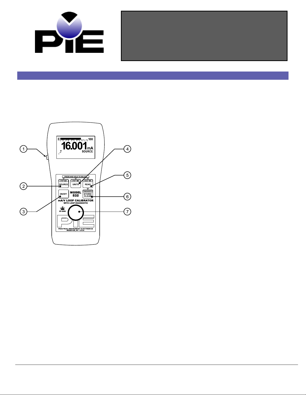
Basic Keypad Operations
EZ-Check™ Switch/EZ-Step™ Pushbut ton
Slide the switch to select the user stored values for calibration
points. Press the button to adjust the output by the user
defined step size. Press and hold the button to activate the
auto step/ramp mode.
UNITS/ STEP TIM E Button
Press and release UNITS/STE P TIME to change how current is
displayed: either in milliamperes or % of 4-20/10-50 mA. Voltage
is only displayed in volts.
Press and hold UNITS/STEP TIME to change step size.
READ/SOAK TIME Button
Press and release READ/SOAK TIME to change read modes.
These are:
• Read Milliamps
• Power and Measure 2-Wire Transmitter
• Read Volts
Press and hold READ/SOAK TIME to change soak time.
STORE/CLEAR Button
In any source mode:
Press STORE/CLEAR to save the current reading in the EZCheck HI or LO position. The EZ-Check switch must be set to HI
or LO. The display will flash “S TORED” to confirm.
In any read mode:
Press STORE/CLEAR to clear the values saved in the EZ-Check
HI and LO positions. The display will flash “CLEARED” to confirm.
EZ-Dial™ Knob
Turn the EZ-Dial knob to adjust the output level. Press and turn
to adjust 100X faster.
SOURCE/STEP S IZE But t o n
Press and release SOURCE/STE P SI Z E to change source
modes. These are:
• Source Milliamps
• 2-Wire Transmitter Simulate
Press and hold SOURCE /STE P SIZ E to change step size.
• Source Volts
ON/OFF Button
Press ON/OFF to turn the Model 535 on or off.
Test Equipment Depot - 800.517.8431 - 99 Washington Street Melrose, MA 02176
1-8
TestEquipmentDepot.com

Model 535 Operating Instructions
Model 535 Configuration
Press the EZ-Dial Knob while turning the Model 535 on to access the configuration mode. Turn
the EZ-Dial Knob to select configuration items. Press the EZ-Dial Knob to change configuration
items. Turn the unit off or just wait approximately 8 seconds to exit the configuration mode.
Auto
Off - ON (default)/OFF
Auto Off is ON, by default, to save battery life by turning the unit off after 30 minutes of inactivity. Turn Auto Off to OFF to prevent
automatic shutdown. This is typically useful for manual loading or continuous use.
EZ-Step - ON/OFF (default)
If EZ-Step is ON manual and automatic stepping/ramping is available. If EZ-Step is OFF the EZ-Step pushbutton will be disabled
and the step direction indicator will not be displayed.
EZ-Check HI/LO Readings ON/OFF (default)
If the EZ-Check HI/LO Readings option is ON, the highest and lowest readings will automatically be saved in the HI and LO EZCheck™ positions.
If this option is OFF the HI and LO positions will show the current reading.
4-20/10-50 Range (default) ON
Select either 4-20 or 10-50 milliamp range. The Model 535 scales % mode display and the bar graph accordingly.
Factory Reset ON/OFF (default)
If Factory Reset is ON, the unit will restore all factory defaults when the Model 535 is turned OFF and back ON. This will reset any
changes made in the Model 535 Configuration options, returning the unit to its simplest factory configuration.
EZ-Dial Knob
Adjust the output up and down with the EZ-Dial knob. The increment is 0.001 mA (or 0.01 % if display units are % of 4-20/10-50
mA.) Press while turning to adjust 100X faster – 0.100 mA (or 1.00 %.)
EZ-Check Switch
The EZ-Check™ switch has three positions -- high, set, and low. Its position is shown at the left edge of the display with “HI” and
“LO” indicators. Use of the EZ-Check switch depends on mode:
Source Modes:
Slide the EZ-Check switch to the HI and LO positions to recall the settings stored in those positions. While in the HI and LO
positions, dial the EZ-Dial knob to change the display. Press STORE/CLEAR to save new settings in the HI and LO positions. The
display will flash “STORED” to confirm.
Hint: For faster calibrations, the posi tion of the switch can be f e l t. This f e atu re allow s continuous monito rin g of t he d e vice being
calibrated without looking back at the Mod e l 535 display. This is a lso use f ul in p oor lighting or under d if f icult op e rat ing conditions.
Read Modes:
In read modes, the Model 535 calibrator records the maximum and minimum readings observed in each mode. Slide the EZ-Check
switch to the HI and LO positions to display the readings. Press STORE/CLEAR to clear the readings. The display will flash
“CLEARED” to confirm. By default, the Model 535 has EZ-Check HI/LO Readings OFF.
EZ-Step Pushbutton/ Manual Step
The EZ-Step pushbutton is a feature only in source modes.
Press and hold the EZ-Step pushbutton for less than one second to cause the output to step up or down by the EZ-Step size.
The EZ-Step direction is indicated on the display ( or ). Press the EZ-Dial knob to change the step direction.
Stepping and auto step/ramp limits are defined by the EZ-Check HI and LO settings. The step direction changes when a limit is
reached.
The step size is computed as the difference between the EZ-Check HI and the EZ-Check LO divided by the number of steps. See
figure 1. By default, the Model 535 has EZ-Step OFF.
Test Equipment Depot - 800.517.8431 - 99 Washington Street Melrose, MA 02176
TestEquipmentDepot.com
2-8

Model 535 Operating Instructions
0
4
8
12
16
20
24
1 2 3 4 5 6 7 8 9 10 11 12 13 14 15
time
mA
time
soak tim e
step size = (EZ-Step HI – EZ-Step LO) ÷ # of steps
step time = ramp time ÷ # of
Auto Step/Ramp
Press the EZ-Step pushbutton for more than one second to activate auto step/ramp mode. The Model 535 will automatically step by
the selected EZ-Step size and time. Press the EZ-Step pushbutton again to deactivate auto step/ramp mode.
The EZ-Step direction is indicated on the display ( or ). Press the EZ-Dial knob to change the step direction. The step
direction can be changed while automatically stepping/ramping.
Stepping and auto step/ramp limits are defined by the EZ-Check HI and LO settings. The step direction changes when a limit is
reached.
Figure 1 will show how the Step/Ramp Parameters are used to configure automatic stepping/ramping.
Figure 1
ramp
The Model 535’s ability to detect overloa d /u nd e rvoltage conditions may b e li mite d b y the rate of chang e in t he ou tput when
Note:
using automatic stepping/ramping. Turn auto step/ramp off while connecting or disconnecting the Model 535.
The Quick Reference Bar Graph indicates the input and output level on the Model 535 in % of 4-20/10-50 mA with 1% resolution.
Test Equipment Depot - 800.517.8431
Quick Reference Bar Graph
- 99 Washington Street Melrose, MA 02176
TestEquipmentDepot.com
3-8

Model 535 Operating Instructions
To Change the EZ -Step Size:
To Change the So ak Time:
To Change the EZ -Step
TM
Direction:
Read Milli am p
Manual Step and Auto Step/Ramp Parameter
1. Press and hold the SOURCE/STEP SIZE button for more than ¾ of a second.
2. The display will flash “EZ-STEP SIZE”.
3. Turn the EZ-Dial knob to select from 2 to 16 steps between the EZ-Check limits.
4. Turn the EZ-Dial clockwise past 16 steps to select continuous ramp mode.
5. Press the SOURCE/STEP SIZE button again to return to the normal display.
Note: If the EZ-Step
To Change the EZ -Step Time:
1. Press and hold the UNITS/ STEP TIME button for more than ¾ of a second.
2. The display will flash “EZ-STEP TIME”.
3. Turn the EZ-Dial knob to select from 5 to 900 second ramp time. The time per step is
calculated based on the selected EZ-Step size.
4. Press the SOURCE / ST E P SIZ E button to return to the normal display.
1. Press and hold the READ/SOAK TIME button for more than ¾ of a second.
2. The display will flash “SOAK TIME”.
3. Turn the EZ-Dial knob to select from 0 to 900 second soak time.
Note: A soak time of 0 defeats the soak period. The step time will be used instead.
4. Press the READ/SOAK TIME button again to return to the normal display.
option is turned of f , th e displa y w ill f lash “EZ-S TEP OFF”.
1. Press and release the EZ-Dial knob without turning.
2. The display will change to show the EZ-Step direction selected ( or ).
Connect the Model 535 in series with the process loop to
monitor current. Observe correct polarity. Current
limiting above 24 mA (52 mA if 10-50 range is selected)
is indicated by a flashing “CURRENT LIMITED” display.
Modes of Operation
Test Equipment Depot - 800.517.8431 - 99 Washington Street Melrose, MA 02176
TestEquipmentDepot.com
4-8

Model 535 Operating Instructions
Read Volts
Power and Measure 2 Wire Transmitter
The Model 535 provides power to the process loop while
displaying output current. Use this mode to test a
transmitter’s ability to control loop current. Current
limiting above 24 mA (52 mA if 10-50 range is selected)
is indicated by a flashing “CURRENT LIMITED” display.
The Model 535 measures +/- 30 VDC with 4X overrange
ability. The display flashes “OVERRANGE” when the 30
volt limit is exceeded.
Connect the Model 535 directly to 4-20/10-50 mA
receiver equipment, alarms, panel meters, etc. Use the
EZ-Dial Knob and EZ-Check Switch to adjust loop
current. The display flashes “H IGH Ω” when the loop
resistance is too high or the leads are open.
ce Millia m p
Sour
Test Equipment Depot - 800.517.8431
TestEquipmentDepot.com
- 99 Washington Street Melrose, MA 02176
5-8

Model 535 Operating Instructions
Relative Humidity Range
10 % ≤RH ≤90 % (0 to 35 °C), Non-condensing
Battery
4 - AA Alkaline Optional 120 VAC 50/60 Hz AC adaptor included
2 Wire Transmitter Simulate
Substitute the Model535 for a 2 wire transmitter. Use
the EZ-Dial Knob and EZ-Check Switch to adjust loop
current. At least 2 volts of loop power is required, else
the display flashes “CHECK LOOP SUPPLY.”
Sour
ce Volts
The Model 532 sources 0.000-24.000 volts. This is useful
for powering transmitters and receiver equipment. Use
the EZ-Dial Knob and EZ-Check Switch to adjust
output voltage. The display flashes “LOW Ω” when the
output is overloaded.
Specifications
General Specifications:
Unless otherwise indicated all specifications are rated from a nominal 23 °C, 70 % RH for 1 year from calib ra tion with >1 MΩ load
on external banana jack access to 10 Ω current sense (Model 535A).
Operating Temperature Range -20 to 60 °C (-5 to 140 °F)
Storage Temperature Range -30 to 60 °C (-22 to 140 °F)
10 % ≤RH≤ 70 % (35 to 60 °C), Non-condensing
Size 7.00 X 3.30 X 2.21 inches (177.8 x 83.8 x 56.1mm)
Weight 14.0 oz (397 grams)
Miscellaneous Low battery indication with nominal 1 hour of operation left
Over-voltage protection to 120 Vrms (rated for 30 seconds) or 240 Vrms (rated for 15
seconds)
Bar graph display with 1% resolution of 4-20/10-50 mA signal scale
High contrast graphic liquid crystal display with 0.45” (11.4 mm) high digits
Test Equipment Depot - 800.517.8431
TestEquipmentDepot.com
- 99 Washington Street Melrose, MA 02176
6-8

Model 535 Operating Instructions
Accuracy
≤ ± (0.025 % of reading + 0.004 mA)
Temperature Effect
≤ ± 50 ppm/°C of range
Loop Compliance Voltage
≥ 43 Volts
Loop Drive Capability
1200 Ω at 20 mA/800 Ω at 50 mA for entire battery life
Overload/Current Limit Protection
≤ 24 mA (4-20 range)/ ≤ 52.5 mA (10-50 range) nominal
Battery Life
≥ 40 hours typical
Miscellaneous
Open loop or out of compliance conditions are indicated by appropriate error display
Common Specifications for all Current Modes:
Ranges 0.000 to 24.000 mA, -25.00 to 125.00% of 4-20 mA
0.000 to 52.000 mA, -25.00 to 105.00% of 10-50 mA
Resolution 0.001 mA and 0.01 %
Step/Ramp Timebase Accuracy 0.01% of 4.9152 MHz
urce/Power and Measure 2-Wire Transmitter Specifications:
So
Miscellaneous Open loop or out of compliance conditions are indicated by appropriate error display
Battery life in:
Source mode ≥ 18 hrs at 12 mA/≥ 9 hrs at 30 mA typical
Power measure ≥ 10 hrs at 12 mA/≥ 5 hrs at 30 mA typical
Selectable EZ-Step(s) for Source Mode/2-Wire Transmitter Simulation:
2 to 16 selectable step settings
Step size is determined by the selected high & low ranges
Selectable time settings for stepping and soak:
STEP: 5 to 900 seconds SOAK: 0 to 900 seconds
d mA Specifications:
Rea
Voltage Burden ≤ 2V
ire Transmitter Simul ation Spe cific ation s:
2-W
Overload/Current Limit Protection ≤ 24 mA (4-20 range)/ ≤ 52.5 mA (10-50 range) nominal
Loop Voltage Limits 2-90 VDC
Battery life ≥ 40 hour typical
Selectable EZ-Step(s) for Source Mode/2-Wire Transmitter Simulation:
2 to 16 selectable step settings
Step size is determined by the selected high & low ranges
Selectable time settings for stepping and soak:
STEP: 5 to 900 seconds SOAK: 0 to 900 seconds
Test Equipment Depot - 800.517.8431 - 99 Washington Street Melrose, MA 02176
7-8
TestEquipmentDepot.com

Model 535 Operating Instructions
Temperature Effect
≤ ± 200 ppm/°C of range
Input Resistance
≥ 1 MΩ
Source Range:
0.000 to 24.000 VDC
Accuracy
≤±(0.025%RDG + 0.004 V) ±50ppm/°C of range
4-20/10-50 Milliamp mA/V Loop Calibrator
Model 535
Read Volta ge Specifica tio n s :
Range: 0.00 to 30.00 VDC (with 4X over range)
Resolutions 0.01 VDC
Accuracy 0.00 to 30.00 VDC ≤ ± (0.1 % of reading ±0.1 V)
Source Voltage Specifications:
Output Resistance ≤0.3 Ω
Source Current ≥20.000 mA
ring Information:
Orde
Includes:
Calibration Test Data
NIST Traceable Certificate
Carrying Case
60 Hz AC adapter
Option:
50 Hz AC adapter 020-0101
Option:
External banana jack access to internal 10 Ω
current sense.
020-0200 (included)
020-0102 (included)
Model 535A
Our equipment is g ua ran te e d a g ai nst d e f e ctive material and workmanship (e xcluding batte rie s) f or a p e rio d of th re e y e a rs from the
date of shipment . Cla ims under guarantee can be mad e b y returning the equipment prepaid to our factory. The equipment will be
repaired, rep lace d or a d juste d a t our op t ion. The lia b ilit y of P ractical Instrument E le ctronics (PIE) is restricted to that given und er our
guarantee. No responsibility is accepted for d a mag e , loss or other expen se in curre d th roug h sale or use of ou r e q ui p me nt. Un d e r no
condition shall Practical Instrument E le ctronics, Inc. be lia b le f or a ny special, incidental or conse q u e ntia l d a mage.
Test Equipment Depot - 800.517.8431 - 99 Washington Street Melrose, MA 02176
Warranty
8-8
TestEquipmentDepot.com
 Loading...